

Page 1
Bulletin 2100A-E
Page 2
YOKOGAWA founded in 1915 is a world leader in the field of
indicating & measuring instruments and industrial control
instrumentation.
Suzhou Yokogawa Meter Company
Yokogawa Meters &
Instruments Corporation
Yokogawa started its business with analog meters
Yokogawa started its business with analog meters
and products have been widely used at various customers
and products have been widely used at various customers
such as industries, power plants, research laboratories
such as industries, power plants, research laboratories
and schools, etc.
and schools, etc.
Through more than 90 years of analog meters manufacturing,
Through more than 90 years of analog meters manufacturing,
Yokogawa provides you with high quality products
Yokogawa provides you with high quality products
with reliable trademark.
with reliable trademark.
Page 3

CONTENTS
Switchboard Instruments .......................................................
Switchboard Instruments Line-up .........................................
Key to Switchboard Numbering System...............................
Accessories and Parts............................................................
Scale Forms and Divisions ....................................................
DC Ammeters, DC Voltmeters............ 2101A/2181A .............
AC Ammeters, AC Voltmeters............ 2102A/2182A .............
Wattmeters.......................................... 2105A/2185A .............
Varmeters ............................................ 2106A/2186A .............
3
4
5
6
7
9
11
13
16
Power Factor Meters .......................... 2107A/2187A .............
Frequency Meters............................... 2108A/2188A .............
Synchroscope..................................... 2109A.........................
Dimensions and Panel Mounting...........................................
Connection Diagrams .............................................................
ACCESSORIES ........................................................................
20
21
22
23
25
29
1
Page 4

Usage Precautions
Safety instructions for Panel meters
Warning
Indicates usage precautions that must be read to ensure the safety of users and the equipment.
1. Usage environment and conditions
Do not use YOKOGAWA panel meters in locations such
as the following:
• Locations where the ambient temperature is outside
the range of 0 to 40°C
• Locations where relative humidity is outside the range
of 25 to 80%
• Locations subject to vibrations or shock impact
• Locations subject to rain, dripping water, or direct
sunlight
• Locations exposed to large amounts of dust, salt, soot,
or corrosive gases
(sulfurous acid gas, ammonia gas, hydrogen sulfide
gas, or other gases that corrode metals or plastics)
• Locations subject to strong external noise or electromagnetic waves
• Locations subject to large amounts of static electricity
• Locations subject to large amounts of high frequencies
and waveform distortion (e.g., from inverters or
thyristor circuits)
2. Mounting method
Adhere to safety rules at the construction, maintenance and inspection
•Check the appearance of the packing box and panel
meters and confirm that there is no damage.
• Use the metal for mounting panel and ground it.
• If necessary, combine with washers and others and
fasten, in the case of panel boards and switchboards
are thin.
•Fasten nuts of mounting on boards to the proper
torque for the size of screw being used with the proper
tool.
Recommended tightening torque : M3 screws - 0.6N·m
M4 screws - 1.2N·m
M5 screws - 2.0N·m
3. Wiring
Adhere to the following rules when connecting the wires:
•When connecting an instrument with accessories, first
make sure none of the wires are live.
•When connecting main power directly, install and use
the proper fuse.
• The connector terminals on the wires should be
appropriate for the electricity load and terminal size.
• Connect the wires properly as illustrated in the wiring
diagrams of catalogs or on product labels.
• Attach to terminal cover for safety.
•Fasten terminal screws to the proper torque for the
size of screw being used with the proper tool.
Recommended tightening torque : M3 screws - 0.6N·m
M4 screws - 1.2N·m
M5 screws - 2.0N·m
• Instruments that are combined with current transformers (CT) should be properly connected to the secondary side of the CT. Improper connection may result in a
CT failure, burned components, or a fire. When the
secondary side of a CT is disconnected, especially
while the primary side is powered, the secondary side
terminal will carry a high voltage which could result in
electrical shock. Therefore, the secondary side should
be short-circuited before the instrument is disconnected.
4. Usage precautions
• Use the instruments at the front of mounting panel.
•Never touch the inside of mounting panel.
• Use the instrument within the rated specifications.
Failure to do so can cause the equipment to malfunction or result in a failure.
• While the power is on, do not touch any terminals or
open the cover or case.
• The current transformer emits heat while powered, so
do not touch it.
5. What to do if the equipment functions abnor-
mally or fails
• If you notice abnormal heating, or a strange odor,
noises, or smoking or if the equipment seems to have
failed, immediately take steps such as cutting off the
input. Next, contact your YOKOGAWA sales office.
6. Maintenance and inspection
To ensure that your instrument operates properly,
perform the following checks on a regular basis:
• Check for damage to the instrument or accessories
due to heating or other factors.
•Check for loose attachments or screws (always turn off
the power before doing this to ensure safety).
• The instrument covers have been coated with an
antistatic agent to block static electricity. Gently wipe
dirt off the cover surfaces with a soft, dry cloth. Do not
use a wet cloth as this will reduce the effects of the
antistatic coating. Do not allow cloths made from
synthetic materials to contact the cover for an extended period of time, and do not use benzene, paint
thinner, or similar substances. Doing so may cause the
cover to become deformed, discolor it, or cause
cracking.
• If the indicator reading becomes unstable due to static
electricity, coat the front and back of the cover with a
commercially available antistatic agent.
• Instrument service life will vary according to usage
conditions. In general, however, we recommend
replacing the instrument after about 10 years of use.
7. Disposal of product
•Panel meters do not contain batteries.
• Dispose of panel meters as general industrial waste.
8. For aluminum electrolytic capacitors
Frequency meters use aluminum electrolytic capacitors. The lifetime of aluminum electrolytic capacitors
are around 10 years when ambient temperatures are
23°C. If aluminum electrolytic capacitors run down and
meters are damaged, replace new frequency meters.
2
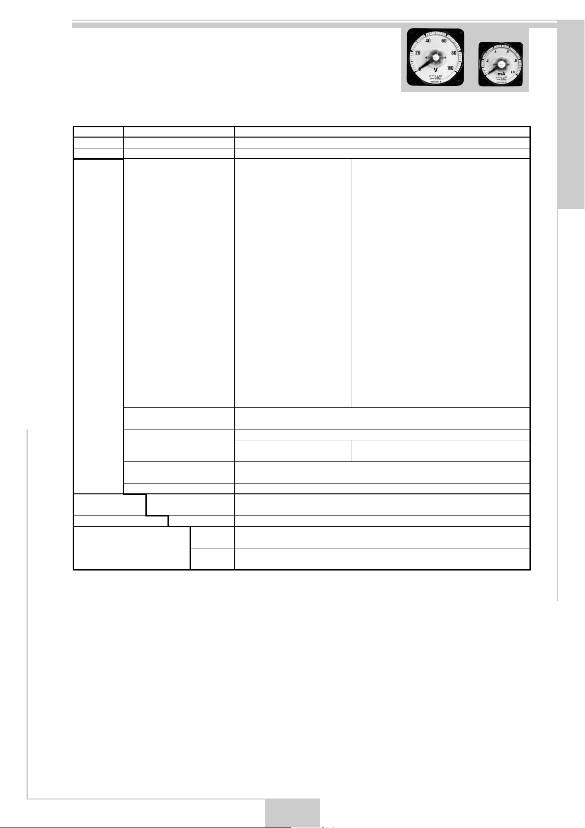
Page 5
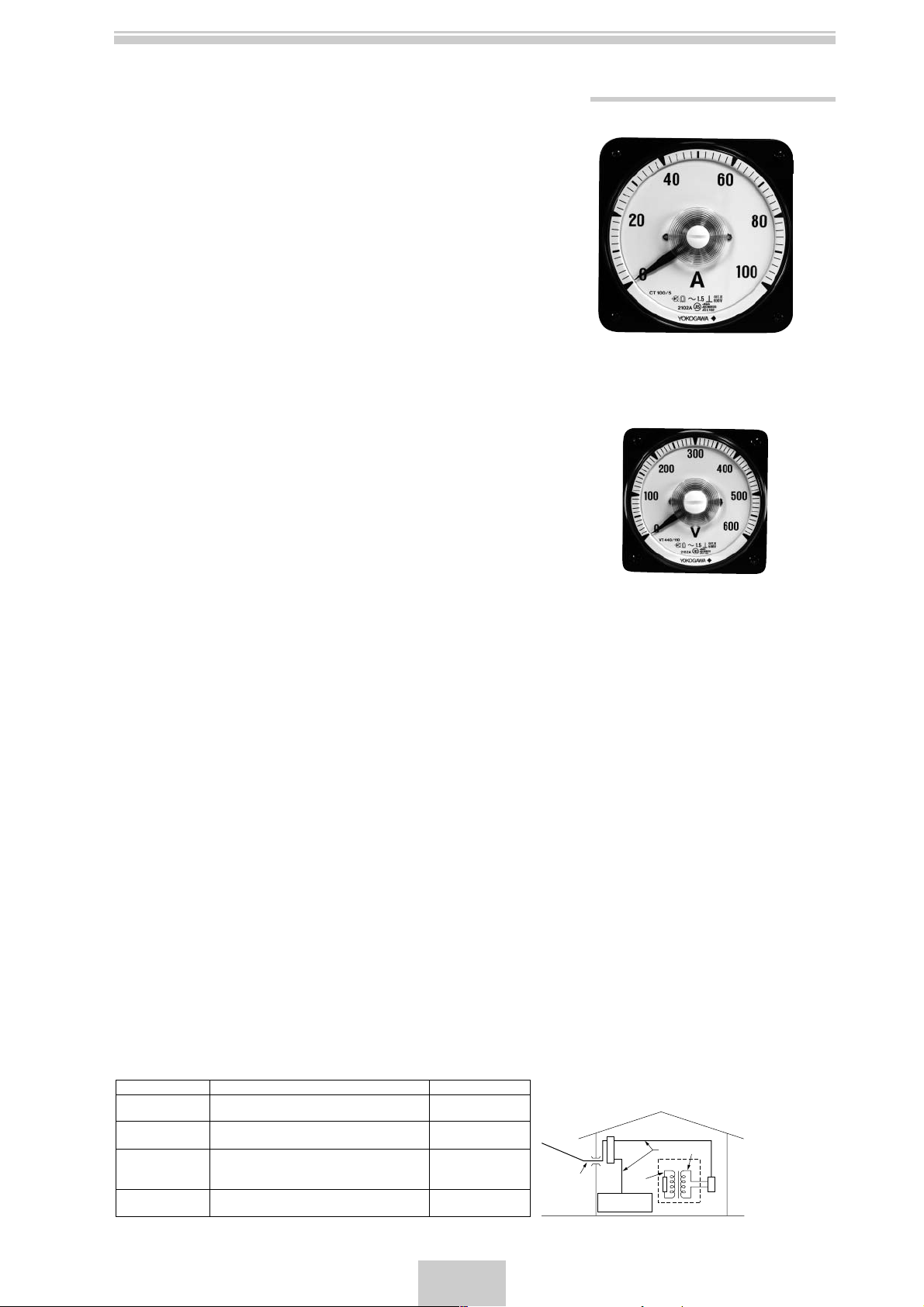
SWITCHBOARD INSTRUMENTS
Yokogawa offers a complete line of switchboard instruments to
meet your every needs.
Model are available 110 mm and 80 mm square siz e 250° to mea-
sure all electrical quantities.
All switchboard instruments in the series feature rugged, friction
free and shock resistant taut-band suspension elements.
All model of AC instruments except 80 mm size wattmeters and
varmeters are self-contained transducer needless external transducer boxes.
The built-in transducer system offer many advantages including
low cost, linear scales, greatly reduced volt-ampere loss.
Yokogawa switchboard instruments offer a variety Models, such
as from single phase to three phase four wire instruments, as well
as model for balanced and unbalanced circuits. All instr uments
except synchroscope are complied with JIS C 1102.
110 mm square size switchboard instruments Series. Plastic case with saf ety terminal protection cover .
Features
■ RMS rectifier type AC instruments
■ Platform scale --- No shadow on scale and readable, even
from sharp angles
■ Interchangeable scales save time
■ Easy to read linear scales and wide deflection angles
■ Taut-Band suspension --- eliminate friction and protects
against shock
■ Unti-framable case and terminal board
■ Provide terminal protect cover for safety
Specifications
In accordance with Japan Industrial Standard JIS C 1102: 2007
■ Accuracy --------------------------------- See next page
■ Full Scale Deflection Angle ---------- 250°(360° for Synchroscope)
■ Full Scale Length ---------------------- Approx. 196mm (7.7") for 110mm SQ
140mm (5.5") for 80mm SQ
■ Position of Use-------------------------- Vertical (Scale)
■ Pointer ------------------------------------ Lance type Pointer, Black
■ Operating Temperature Range ----- 0 to 40 °C
■ Operating Humidity Range ---------- 25 to 80 %RH
■ Storage Temperature Range -------- –10 to 50°C
■ Storage Humidity Range ------------- 25 to 80 %RH
■ Dielectric Strength --------------------- Between electrical circuit and the case: 3320V AC for 5 seconds
Between current circuit and voltage circuit: 2600V AC for 5 seconds
For Wattmeters, Varmeters and Power factormeters
(2000V AC for 2185A, 2186A and 2187A)
■ Insulation Resistance ----------------- More than 10 MΩ/500V DC between electrical circuit and the case,
current circuit and voltage circuit.
More than 5MΩ/500V DC between current circuit and voltage circuit.
For Wattmeters, Varmeters and Power factormeters
■ Safety Requirements------------------ Structural requirements are in accordance with JIS C 1010 for safety of
voltage test, insulation and other.
Reinforced insulation, between electrical circuit and case
Indoors, Altitudes up to 2000m, Pollution degree 2
Measurement category III
(Measurement category is not applied for non- JIS products.)
Maximum working voltage:600V
80 mm square size miniature switchboard instruments series high space utility.
Type 2101A to 2109A
Type 2181A to 2188A
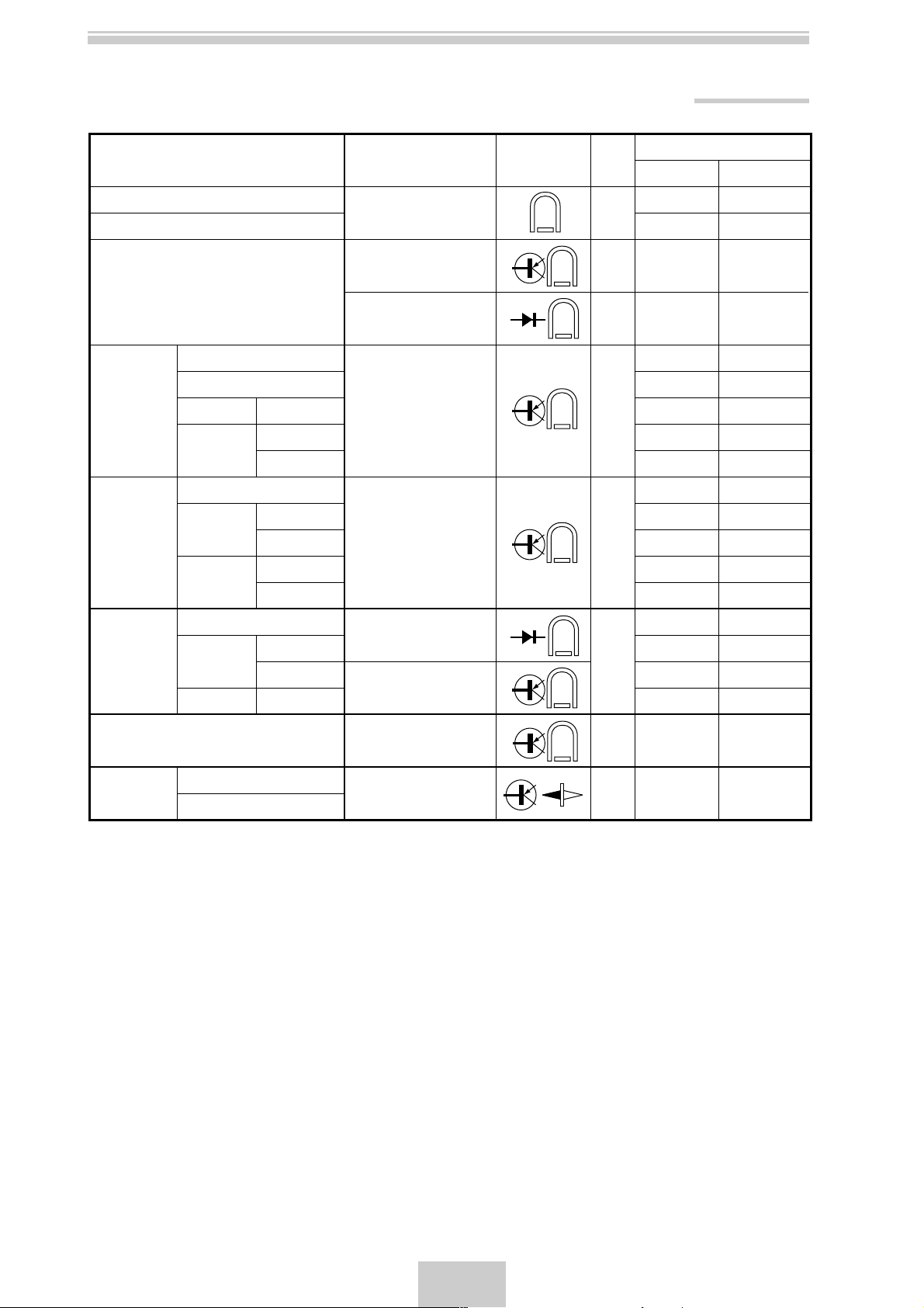
Measurement Category
Measurement Category
CAT.I
CAT.II
CAT.III
CAT.IV
For measurements performed on circuits not
Description
directly connected to MAINS.
For measurements performed on circuits directly
connected to the low voltage installation.
For measurements performed in the building
where distribution panels and circuit breaker, etc
are installed.
For measurements performed at the source of
the low-voltage installation.
Remarks
Appliances, portable
equipments, etc.
Distribution board,
circuit breaker, etc.
Overhead wire, cable
systems, etc.
3
Entrance
Cable
CAT.IV
Internal Wiring
Distribution
Board
CAT.I
Fixed Equipment,
etc.
CAT.III
CAT.II
T
Equipment
Outlet
Page 6
SWITCHBOARD INSTRUMENTS LINE UP
Name
DC AMMETERS / VOLTMETERS
DC SUPPRESSED METERS
AC AMMETERS / VOLTMETERS
Single phase 2-wire
Single phase 3-wire
WATTMETERS
VARMETERS
POWER
FACTOR
METERS
3-phase 3-wire
3-phase 4-wire
Single phase 2-wire
3-phase 3-wire
3-phase 4-wire
Single phase 2-wire
3-phase 3-wire
3-phase 4-wire
(Unbalanced)
(Balanced)
(Unbalanced)
(Balanced)
(Unbalanced)
(Balanced)
(Unbalanced)
(Balanced)
(Unbalanced)
(Unbalanced)
Operating Princile
Moving coil type
RMS rectifier type
Mean rectifier type
Feedback time division
multiplier type
Feedback time division
multiplier type
Phase defection type
Feedback time division
multiplier type
Symbol
Accuracy
1.5
1.5
2.5
1.5
1.5
5.0
Model
110mm SQ
2101A30
2101A35,36,37
2102A30
2102A31
2105A31
2105A32
2105A35
2105A34
2105A36
2106A31
2106A33
2106A35
2106A34
2106A36
2107A31
2107A33
2107A35
2107A36
80mm SQ
2181A00
2181A35,36,37
2182A00
2182A01
2185A31(*1)
2185A32(*1)
2185A35(*1)
2185A34(*1)
2185A36(*1)
2186A31(*1)
2186A33(*1)
2186A35(*1)
2186A34(*1)
2186A36(*1)
2187A31
2187A33
2187A35(*1)
2187A36(*1)
FREQUENCY METERS
SYNCHROSCOPE (*2)
Note:
*1: Attached external transducer box.
*2: not complied with JIS standard.
Single phase
3-phase
Differential type
Moving Magnet type
0.5
1.0
2.5
2108A30
2109A30
2188A30
—
4
Page 7
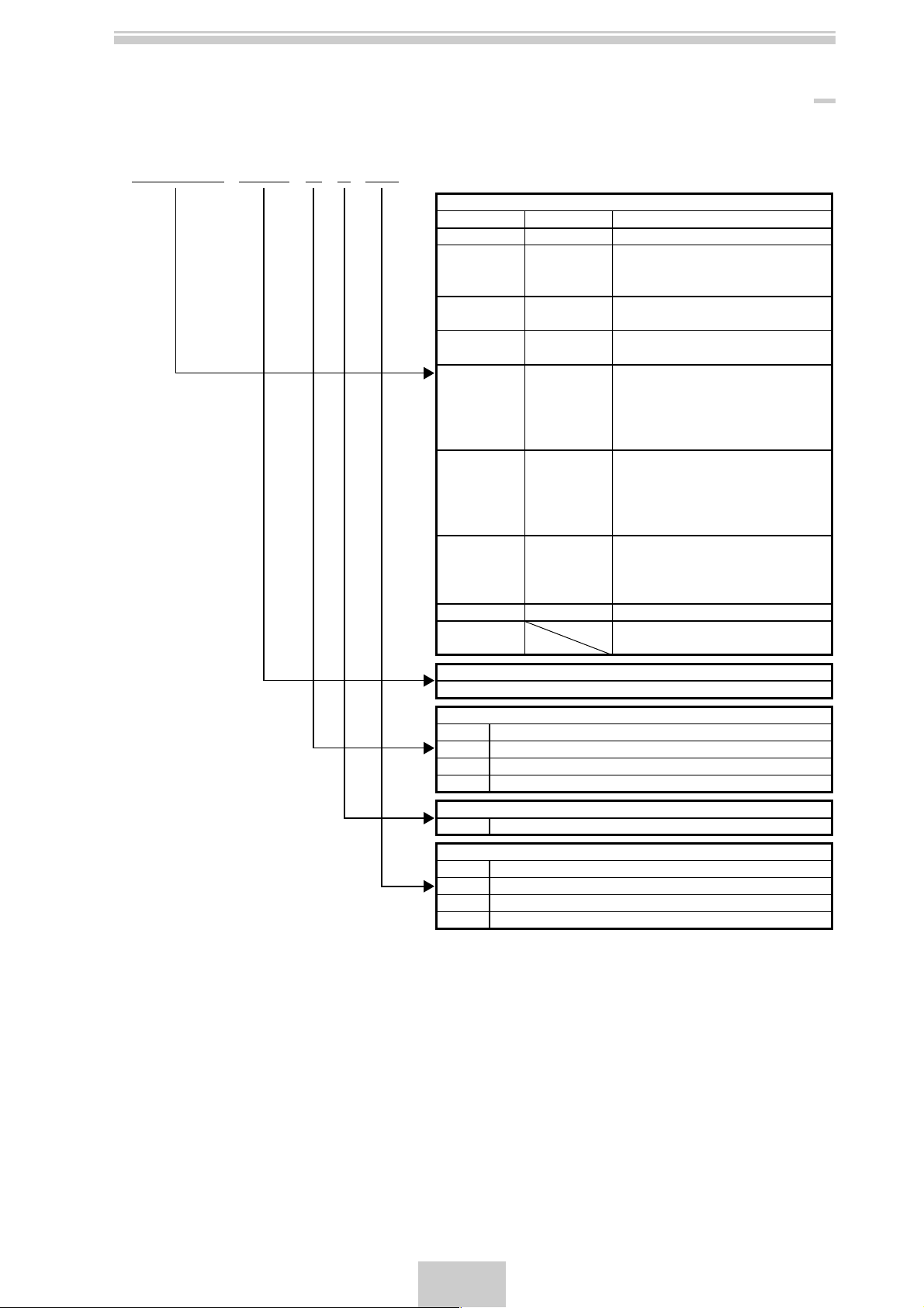
KEY TO SWITCHBOARD NUMBERING SYSTEM
[Model/Suffix Code]
21
앮앮
(A)
앮앮
앮앮앮
-
- 앮 - L -
앮앮
Model
110 SQUARE
2101A 30
2101A 35
2102A 30
2102A 31
2105A 31
2106A 31
2107A 31
2108A 30
2109 31
Rating
Refer to Suffix Code
Designation of Frequency Used
N
A
B
C
Pointer
L Lance type pointer
Cover color and Set pointer
BL
BG
BS
GS
80 SQUARE
2181A 00
2181A 35
36
37
2182A 00
2182A 01
2185A 31
32
34
35
36
2186A 31
33
34
35
36
2187A 31
33
35
36
2188A 30
33
Always "N" or 50/60Hz Common
50Hz
60Hz
400Hz
Munsell N1.5
Munsell 7.5BG4/1.5
Munsell N1.5 with Set pointer (red color)
Munsell 7.5BG4/1.5 with Set pointer (red color)
* Specify Full scale value and Unit
DC AMMETERS,DC VOLTMETERS
DC AMMETERS ,VOLTMETERS
36
SUPPRESSED METER
37
AC AMMETERS ,VOLTMETERS
RMS rectifier type
AC AMMETERS ,VOLTMETERS
Mean rectifier type
32
34
WATTMETERS
35
36
33
34
VARMETERS
35
36
33
POWER FACTOR METERS
35
36
FREQUENCY METERS
SYNCHROSCOPE
5
Page 8

[EX.]
Model
110 SQUARE AC AMMETERS
Rating
0 to 5A
Full scale value
and Unit
0 to 100A
Designation of
Frequency Used
50/60Hz Common
2102A30-A42-N-L-BL
ACCESSORIES AND PAR TS
Model
1set (Specify Model and suffix codes, Full scale value
Standard Scale Plate
Blank Scale Plate (With YOKOGAWA mark)
Cover
110 SQUARE
80 SQUARE
Terminal Cover (6 Terminal)
Terminal Cover (5 Terminal)
Terminal Cover (3 Terminal):(For 80 SQUARE)
Shunt lead
Cover with Set
pointer
Cover
Cover with Set
pointer
(Black)
(Blue Green)
(Black)
(Blue Green)
(Black)
(Blue Green)
(Black)
(Blue Green)
219900
219900/001
219930-11
219930-12
219930-13
219930-14
219930-31
219930-32
219930-33
219930-34
219930-22
219930-21
219930-23
219930-24
and unit,VT ratio and CT ratio)
EX.: 2101A36-AHE-N-L-BL 0 to 250kPa
1set (Specify Model and suffix codes, and Blank scale)
EX.: 2101A36-AHE-N-L-BL Blank scale
1 pce
1 pce
1 pce (Set pointer is red)
1 pce (Set pointer is red)
1 pce
1 pce
1 pce (Set pointer is red)
1 pce (Set pointer is red)
10 sheets (up side)
10 sheets (down side)
10 sheets
Round Resits 0.05Ω less, For M4 terminal, 1.5m 1set
Pointer
Lance type pointer
0 to 100A
Descriptions
Cover color and
Set pointer
Munsell N1.5
6
Page 9
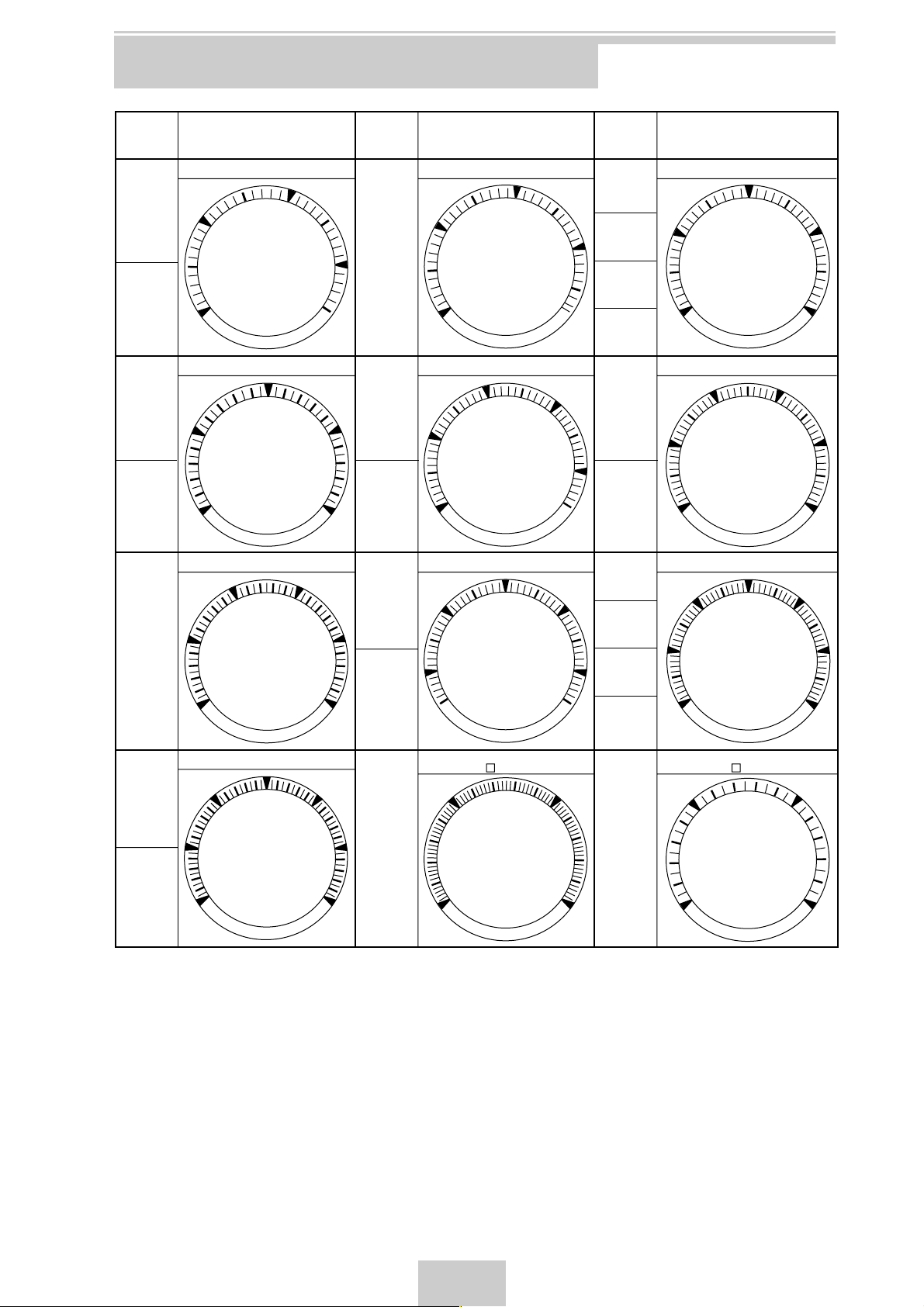
SCALE FORMS AND DIVISIONS
Maximum
scale
value
3.5
35
350
3500
7
70
700
7000
2
20
200
2000
±1
±10
±100
±1000
2.5
25
250
2500
3
30
300
3000
±1.5
±15
±150
±1500
Maximum
Divisions
scale
Divisions
value
35 Division
7.5
75
750
7500
40 Division B
4.5
45
450
4500
9
90
900
9000
50 Division B 50 Division C 60 Division A
±2.5
±25
±250
±2500
±5
±50
±500
±5000
60 Division B
1.5
15
150
1500
37.5 Division
45 Division
75 Division
For 210 A 110mm only
Maximum
scale
value
4
40
400
4000
8
80
800
8000
±2
±20
±200
±2000
±4
±40
±400
±4000
1
10
100
1000
5
50
500
5000
1.2
12
120
1200
6
60
600
6000
±3
±30
±300
±3000
±6
±60
±600
±6000
1.5
15
150
1500
Divisions
40 Division A
50 Division A
30 Division
For 218 A 80mm only
Note 1. This standard scale divisions are applied to 2101A, 2102A, 2105A, 2106A, 2181A, 2182A, 2185A and 2186A.
2. Numerals are indicated to the major line (▼).
3. All scales divisions are linear distribution.
4. To be applied this standard scale division, when specify special maximum value.
•not standard maximum scale value (Ex.) 2300 --- 46 divisions
•minimum scale value are not zero (Ex.) 50 to 100 --- 50 divisions
7
Page 10
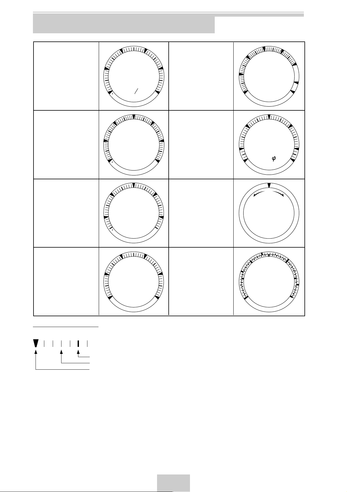
SCALE FORMS AND DIVISIONS
For Suppressed meter
2101A, 2181A
For Expanded scale
2102A, 2182A voltmeter
Ex.
70 to 130V=245°
For Frequency meter
2108A, 2188A
Ex.
45 to 55Hz
1
80
46
0
70
48
45
90
Extended scale Ammeters
2
3
4
5
3
m
s
2102A, 2182A
(Ex.)100A 2 times
Red line and numerals for
extended portion
(Ex. 2 Times 150 and 200A)
3 Times -- 2 and 3 Times
5 Times -- 3 and 5 Times
100
110
For Power Factor meter
120
130
V
2107A, 2187A
60
40
20
0
A
1.0
.9
LEAD LAG
.7
.5
COS
80
100
150
200
.9
.7
.5
50
52
For Synchroscope
2109A
SLOW
FAST
54
Hz
55
SYNCROSCOPE
Single division/Double
numerals
Ex. 0 to 5/0 to 10A (50 Div.)
All div.line and numerals
are black.
Size of numerals are
different high.
Apply same division only.
Kinds of division lines
1. Kinds of division lines
Medium line
Minor line
Major line (with numerals)
2. 3 characters, standard.
EX. (1) 1200V → 1.2kV
(2) 20000rpm → 20 × 1000rpm
4
2
2
1
0
6
3
8
4
10
A
5
Double division/Double
numerals
Ex.0 to 300/0 to 450 m/min
(60 Div./45 Div.)
Outer -- Black line and
numerals
Inner -- Red line and
numerals
10
5
0
20
10
m/min
15
30
20
30
45
25
40
8
Page 11
2101A/2181A
DC AMMETERS
-AEG
-AEM
-AFA
-AFN
-AFX
-AGZ
-AHM
-AHY
-AJR
-AKG
-AKM
-ALA
-ALC
-ALE
-ALJ
-ALS
-AMF
-AMT
-AND
-ANG
-ANL
-A00
-D00
-A01
-A04
-A05
-D00
-A06
Suffix Codes
-N
-L
-BL
-BG
-BS
-GS
110 SQUARE Class 1.5
80 SQUARE Class 1.5
0 to 300 microA (Approx. Internal Resistance : 1,050 ohm)
0 to 500 microA (Approx. Internal Resistance : 630 ohm)
0 to 1mA (Approx. Internal Resistance : 185 ohm)
0 to 3mA (Approx. Internal Resistance : 17 ohm)
0 to 5mA (Approx. Internal Resistance : 10 ohm)
0 to 10mA
0 to 30mA
0 to 50mA
0 to 100mA
0 to 300mA
0 to 500mA
0 to 1A
0 to 1.5A
0 to 2A
0 to 3A
0 to 5A
0 to 7.5A
0 to 10A
0 to 15A
0 to 20A
0 to 30A
0 to (300 microA to 1A),
Optional intermediate rating
-a to 0 to +b where a or less 72% × (a+b), a+b=1mA to 2A
For zero-center and similar scale meter
0 to 50mV, For external shunt use
0 to 60mV Specify scale range
0 to 100mV (No shunt is manufactured)
-a to 0 to +b (b=50mV) where a or less 50mV,
For zero-center and similar scale meter
0 to 50mV, Meter with VR, 0 to 2 ohm Variable
Always "-N"
Lance type pointer (Black), Always "-L"
Munsell N1.5
Munsell 7.5BG4/1.5
Munsell N1.5 with Set pointer (red color)
Munsell 7.5BG4/1.5 with Set pointer (red color)
Model
2101A 30
2181A 00
Rating
Designation of
Frequency Used
Pointer
Cover color and Set pointer
SPECIFY THE FOLLOWING WHEN ORDERING
(1) Model and Suffix codes
(2) Full scale value and unit
(3) For suffix code A00 or D00, specifiy rating and full scale value.
Descriptions
(Voltage Drop : 50mV)
Notes :
(1) Scale other than Yokogawa' standard format will be special order.
(2) For each meter with the rating of 50mV,60mV or 100mV, one-pair(1.5m) of shunt leads are supplied.
(3) External shunts are not supplied.
9
Page 12

DC V OL TMETERS
Model
2101A 30
2181A 00
Rating
Designation of
Frequency Used
Pointer
Cover color and Set pointer
SPECIFY THE FOLLOWING WHEN ORDERING
(1) Model and Suffix codes
(2) Full scale value and unit
(3) For suffix code E00,V00,V07,V08 or V11, specifiy rating and full scale value.
Notes :
(1) Scale other than Yokogawa' standard format will be special order.
(2) External multiplierare not supplied.
(3) *: For non- JIS products.
-VLA
-VLJ
-VLS
-VMT
-VNL
-VNT
-VPK
-VRX
-VSF
-VSJ
-V00
-V07
-V08
-E00
-E00*
-V01*
-V11
-N
Suffix Codes
-L
-BL
-BG
-BS
-GS
110 SQUARE Class 1.5
80 SQUARE Class 1.5
0 to 1V
0 to 3V
0 to 5V
0 to 10V
0 to 30V
0 to 50V
0 to 100V
0 to 300V
0 to 500V
0 to 600V
0 to (50mV to 600V),
Optional intermediate rating
0 to (1V to 300V), Current Consumption : 300 microA
Optional full scale value Current Consumption : 500 microA
-a to 0 to +b where a or less 72% × (a+b), a+b=100mV to 600V
For zero-center and similar scale meter
-a to 0 to +b (b=1mA) where a or less 1mA, For zero-center and similar scale meter
0 to 1mA For external multiplier
0 to (10V to 300V) Optional intermediate rating, Voltmeter with VR,
(Current Consumption : 1mA), ±25% Variable
Always "-N"
Lance type pointer (Black), Always "-L"
Munsell N1.5
Munsell 7.5BG4/1.5
Munsell N1.5 with Set pointer (red color)
Munsell 7.5BG4/1.5 with Set pointer (red color)
Descriptions
(Current Consumption : 1mA),
Where less than 1V : 2mA
DC AMMETERS ,VOLTMETERS SUPPRESSED METER
Descriptions
-AHX
-AHE
-VLR
-N
Suffix Codes
-L
-BL
-BG
-BS
-GS
110 SQUARE Class 1.5
80 SQUARE Class 1.5
10 to 50mA DC, General type (Approx. Internal Resistance : 13 ohm)
4 to 20mA DC, General type (Approx. Internal Resistance : 6 ohm)
1to 5V DC, General type (Approx. Internal Resistance : 4k ohm)
Always "-N"
Lance type pointer (Black), Always "-L"
Munsell N1.5
Munsell 7.5BG4/1.5
Munsell N1.5 with Set pointer (red color)
Munsell 7.5BG4/1.5 with Set pointer (red color)
Model
2101A
2181A
Rating 35
36
37
Designation of
Frequency Used
Pointer
Cover color and Set pointer
SPECIFY THE FOLLOWING WHEN ORDERING
(1) Model and Suffix codes
(2) Full scale value and unit
(3) Specifiy TagNO., if necessary.
Notes :
(1) Special unit symbol is available to suppressed meters.
Standard symbol is small letter.
Specify "Capital letter", if necessary.
EX.: M/MIN,TON,etc.
(2) Scale other than Yokogawa' standard format will be special order.
10
Page 13
2102A/2182A
AC AMMETERS, VOLTMETERS
RMS rectifier type
-ALA
-ALJ
-ALS
-AMT
-ANL
-A00
-A41
-A42
-A21
-A22
-A25
-A26
-A32
-A34
-A35
-A36
-A52
-A55
-A43
-A44
-A45
-A46
-A47
-A48
-VNT
-VPK
-VPZ
-VRX
-VSJ
-V00
-V12
-V13
-V20
-V21
Suffix Codes
-N
-C
-L
-BL
-BG
-BS
-GS
110 SQUARE Class 1.5
80 SQUARE Class 1.5
0 to1A
0 to 3A
0 to 5A
0 to 10A
0 to 30A
0 to (1A to 30A) Optional intermediate rating
0 to 1A
0 to 5A
0 to 0.5 to 1 A
0 to 1 to 2 A
0 to 5 to 10A
0 to 10 to 20 A
0 to 1 to 3 A
0 to 3 to 9A
0 to 5 to 15 A
0 to 10 to 30A
0 to 1 to 5A
0 to 5 to 25A
0 to 1 to 2A
0 to 5 to 10A
0 to 1 to 3A
0 to 5 to 15A
0 to 1 to 5A
0 to 5 to 25A
0 to 50V (Power Consumption : 0.1VA)
0 to 100V (Power Consumption : 0.6VA)
0 to 150V (Power Consumption : 0.9VA)
0 to 300V (Power Consumption : 1.8VA)
0 to 600V (Power Consumption : 1.2VA)
0 to (50V to 600V), Optional intermediate rating
0 to 150V For use with external VT (Power Consumption : 0.9VA)
0 to 150/ √3V For use with external VT (Power Consumption : 0.2VA)
Expanded scale 70 to 130V (Power Consumption : 0.5VA)
Expanded scale 140 to 260V (Power Consumption : 1.0VA)
50/60Hz Common
400Hz
Lance type pointer (Black), Always "-L"
Munsell N1.5
Munsell 7.5BG4/1.5
Munsell N1.5 with Set pointer (red color)
Munsell 7.5BG4/1.5 with Set pointer (red color)
Two-fold extended (For external CT)
Three-fold extended (For external CT)
Five-fold extended (For external CT)
Model
2102A 30
2182A 00
Rating
Designation of
Frequency Used
Pointer
Cover color and Set pointer
SPECIFY THE FOLLOWING WHEN ORDERING
(1) Model and Suffix codes
(2) Full scale value and unit
(3) For suffix code A00 or V00, specifiy rating and full scale value.
(4) VT ratio and CT ratio
Notes :
VT and CT are not supplied.
Descriptions
(For external CT)
Two-fold extended
Three-fold extended
Five-fold extended
(Power
Consumption :
0.4VA)
11
Page 14

AC AMMETERS, VOLTMETERS
Mean rectifier type
-AEG
-AEM
-AFA
-AFN
-AFX
-AGZ
-AHM
-AHY
-AJR
-AKG
-AKM
-A00
-VLJ
-VLS
-VMT
-VNL
-VNT
-VPK
-VPZ
-VRX
-VSJ
-V00
-V11
-V12
-V13
Suffix Codes
-N
-C
-L
-BL
-BG
-BS
-GS
110 SQUARE Class 2.5
80 SQUARE Class 2.5
300 microA
500 microA
0 to 1mA
0 to 3mA
0 to 5mA
0 to 10mA
0 to 30mA
0 to 50mA
0 to 100mA
0 to 300mA
0 to 500mA
0 to (300 microA to 500mA)
Optional intermediate rating
0 to 3V
0 to 5V
0 to 10V
0 to 30V
0 to 50V
0 to 100V
0 to 150V
0 to 300V
0 to 600V
0 to (3V to 600V)
Optional intermediate rating
0 to (10V to 300V)
Optiona intermediate rating,
Voltmeter with VR
0 to 150V
(For external VT use)
0 to 150 √3V
(For external VT use)
50/60Hz Common
400Hz
Lance type pointer (Black), Always "-L"
Munsell N1.5
Munsell 7.5BG4/1.5
Munsell N1.5 with Set pointer (red color)
Munsell 7.5BG4/1.5 with Set pointer (red color)
Model
2102A 31
2182A 01
Rating
Designation of
Frequency Used
Pointer
Cover color and Set pointer
SPECIFY THE FOLLOWING WHEN ORDERING
(1) Model and Suffix codes
(2) Full scale value and unit
(3) For suffix code A00, V00 or V11, specifiy rating and full scale value.
(4) VT ratio and CT ratio
Descriptions
(Voltage Drop : 3V)
(Internal Resistance Value 900ohm/V)
Notes :
VT and CT are not supplied.
12
Page 15

2105A/2185A
WATTMETERS
Model Suffi x Codes Descriptions
2105A 31 Single phase 2-wire
2105A 32 Single phase 3-wire
2105A 35 3-phase 3-wire (Unbalanced)
2105A 34 3-phase 4-wire (Balanced)
2105A 36 3-phase 4-wire (Unbalanced)
2185A 31 Single phase 2-wire
2185A 32 Single phase 3-wire
2185A 35 3-phase 3-wire (Unbalanced)
2185A 34 3-phase 4-wire (Balanced)
2185A 36 3-phase 4-wire (Unbalanced)
Rating
(Zero-left) -W14 110V/5A
(Off-center) -S13 110V/1A Zero-center and similar
Designation of
Frequency Used
Pointer
Cover color and Set pointer
SPECIFY THE FOLLOWING WHEN ORDERING
(1) Model and Suffi x codes
(2) Full scale value and unit
(3) In case of using external CT/or VT, calculate the possible full scale value
form the following page and be sure that is within the range shown avove.
(4) VT ratio and CT ratio
Notes :
VT and CT are not supplied.
-W13 110V/1A
-W15 220V/1A
-W16 220V/5A
-W19 110/220V 1A
-W20 110/220V 5A
-W21 220/440V 1A
-W22 220/440V 5A
-W13 110V/1A
-W14 110V/5A
-W15 220V/1A
-W16 220V/5A
-W11 110/
-W12 110/
-W17 220/
-W18 220/
-W51 100V/1A
-W52 100V/5A
-W53 115V/1A
-W54 115V/5A
-W55 120V/1A
-W56 120V/5A
-W61 200V/1A
-W62 200V/5A
-W63 230V/1A
-W64 230V/5A
-W65 240V/1A
-W66 240V/5A
-S14 110V/5A
-S15 220V/1A
-S16 220V/5A
-S13 110V/1A
-S14 110V/5A
-S15 220V/1A
-S16 220V/5A
-S53 115V/1A
-S54 115V/5A
-S11 110/
-S12 110/
-S17 220/
-S18 220/
-N 50/60Hz Common
-C 400Hz
-L Lance type pointer (Black), Always "-L"
-BL Munsell N1.5
-BG Munsell 7.5BG4/1.5
-BS Munsell N1.5 with Set pointer (red color)
-GS Munsell 7.5BG4/1.5 with Set pointer (red color)
_
3V 1A
√
_
3V 5A
√
_
3V 1A
√
_
3V 5A
√
_
3V 1A
√
_
3V 5A
√
_
3V 1A
√
_
3V 5A
√
scale
Scale : -a W to 0 to +b
W where a
For calibration power
range : The "+b" side
is the same as its
standard power where a
b
b
110 SQUARE Class 1.5
80 SQUARE
With external
transducer
Single phase 2-wire
Single phase 3-wire
3-phase 3-wire
3-phase 4-wire
Semi-standard meters
For 21
Single phase 2-wire
3-phase 3-wire
3-phase 4-wire
5A31,35
Class 1.5
13
Page 16

WATTMETERS
[Available Calibration Watts]
Standard Rating Available Calibration Watts
VOLTAGE
110/ √_3V
Operating
voltage range
52 to 75V
CURRENT
1A
5A
Single phase
2-wire
48 to 80W
240 to 400W
Single phase
3-wire
-
-
3-phase
3-wire
-
-
3-phase
4-wire
125 to 285W
625 to 1400W
110V
115V
120V
220/ √_3V
200V
220V
240V
(1) Calibration Watts are 65 to 150%. Standard Watts beyond the limits are not available.
Single phase 2-wire:Standard Watts = Voltage Rating × Current Rating
Single phase 3-wire:Standard Watts = 2 × Voltage Rating (P1-N) × Current Rating
3-phase 3-wire:Standard Watts = root3 × Line Voltage Rating × Current Rating
3-phase 4-wire:Standard Watts = 3 × Phase Voltage Rating × Current Rating
(2) When using VT and CT, Caribration watts will be as follows;
Connection
EX.1
EX.2
3-phase
Single phase
90 to 130V
104 to 150V
180 to 260V
Caribration watts =
Full scale
value
3-wire
2-wire
7.5kW
20kW
1A
5A
1A
5A
1A
5A
72 to 164W
360 to 820W
-
-
144 to 328W
720 to 1640W
MAX.Full scale value
(VT ratio) × (CT ratio)
VT ratio
440/110V
660/110V
CT ratio
30/5A
20/5A
145 to 330W
715 to 1650W
290 to 660W
1430 to 3300W
FS=
440/110 × 30/5
FS=
660/110 × 20/5
-
-
20kW
7.5kW
125 to 285W
625 to 1400W
-
-
250 to 570W
1250 to 2850W
Calibration watts
=833.3W Available
=312W Special order with TOKUCHU sheet
-
-
250 to 570W
1250 to 2850W
-
-
14
Page 17

2800
⬃⬃⬃⬃⬃⬃⬃⬃⬃⬃⬃⬃⬃⬃⬃⬃⬃
Single-Phase 3-Wire
1250
984
⬃⬃⬃⬃⬃⬃⬃⬃⬃⬃⬃⬃⬃⬃⬃⬃⬃
432
=W, =kW, =MW
492
⬃⬃⬃⬃⬃⬃⬃⬃⬃⬃⬃⬃⬃⬃⬃⬃⬃
216
328
⬃⬃⬃⬃⬃⬃⬃⬃⬃⬃⬃⬃⬃⬃⬃⬃⬃
144
164
⬃⬃⬃⬃⬃⬃⬃⬃⬃⬃⬃⬃⬃⬃⬃⬃⬃
72
98.4
⬃⬃⬃⬃⬃⬃⬃⬃⬃⬃⬃⬃⬃⬃⬃⬃⬃
43.2
4200
5600
8400
1875
2500
3750
1476
1968
2952
1296
648
864
738
984
1476
324
432
648
492
656
984
216
288
432
246
328
492
108
144
216
147.6
196.8
295.2
64.8
86.4
129.6
14
16.8
28
6.25
7.5
12.5
4920
5904
9840
2160
2592
4320
2460
2952
4920
1080
1296
2160
1640
1968
3280
720
864
1440
820
984
1640
360
432
720
492
590.4
984
216
259.2
432
42
56
70
18.75
25
31.25
14.76
19.68
24.6
6.48
8.64
10.8
12.3
7380
9840
5.4
3240
4320
4920
6560
8200
2160
2880
3600
2460
3280
4100
1080
1440
1800
1476
1968
2460
648
864
1080
84
140
168
37.5
62.5
75
29.52
49.2
59.04
12.96
21.6
25.92
14.76
24.6
29.52
6.48
10.8
12.96
16.4
19.68
9840
7.2
8.64
4320
4920
8200
9840
2160
3600
4320
2952
4920
5904
1296
2160
2592
210
280
420
93.75
125
187.5
73.8
98.4
147.6
32.4
43.2
64.8
36.9
49.2
73.8
16.2
21.6
32.4
24.6
32.8
49.2
10.8
14.4
21.6
12.3
16.4
24.6
5.4
7.2
10.8
14.76
7380
9840
6.48
3240
4320
560
250
196.8
86.4
98.4
43.2
65.6
28.8
32.8
14.4
19.68
8.64
10.08
16.8
25.2
33.6
42
50.4
84
100.8
126
168
37.5
45
56.25
75
42
50.4
63
84
18.75
22.5
28.13
37.5
28
33.6
42
56
12.5
15
18.75
25
14
16.8
21
28
6.25
7.5
9.375
12.5
10.08
12.6
16.8
8400
4.5
5.625
7.5
3750
252
112.5
126
56.25
84
37.5
42
18.75
25.2
11.25
1680
2520
3360
5040
8400
⬃⬃⬃⬃⬃⬃⬃⬃⬃⬃⬃⬃⬃⬃⬃⬃⬃
4.5
7.5
11.25
15
18.75
12.6
16.8
8400
5.625
7.5
3750
11.2
5600
8400
5
2500
3750
2800
4200
5600
1250
1875
2500
1680
2520
3360
750
1125
1500
22.5
21
25.2
9.375
11.25
14
16.8
6.25
7.5
7000
8400
3125
3750
4200
5040
1875
2250
750
1125
1500
2250
3750
840
1260
1680
2520
4200
562.5
750
1125
840
1120
1680
375
500
750
420
560
840
187.5
250
375
252
336
504
112.5
150
225
5040
1875
2250
2800
3360
1250
1500
1400
1680
625
750
840
1008
375
450
⬃⬃⬃⬃⬃⬃⬃⬃⬃⬃⬃⬃⬃⬃⬃⬃⬃
375
560
⬃⬃⬃⬃⬃⬃⬃⬃⬃⬃⬃⬃⬃⬃⬃⬃⬃
250
⬃⬃⬃⬃⬃⬃⬃⬃⬃⬃⬃⬃⬃⬃⬃⬃⬃
280
125
168
⬃⬃⬃⬃⬃⬃⬃⬃⬃⬃⬃⬃⬃⬃⬃⬃⬃
75
336
150
168
75
112
50
56
25
33.6
15
14.85
22.28
29.7
44.55
59.4
74.25
89.1
148.5
178.2
222.8
297
65.4
78.48
74.25
89.1
32.7
39.24
49.5
59.4
21.8
26.16
24.75
29.7
10.9
13.08
14.85
17.82
6.54
7.848
98.1
130.8
111.4
148.5
49.05
65.4
74.25
99
32.7
43.6
37.13
49.5
16.35
21.8
22.28
29.7
9.81
13.08
445.5
196.2
222.8
98.1
148.5
65.4
74.25
32.7
44.55
19.62
2970
4455
5940
8910
⬃⬃⬃⬃⬃⬃⬃⬃⬃⬃⬃⬃⬃⬃⬃⬃⬃
6.54
9.81
13.08
19.62
26.16
32.7
14.85
22.28
29.7
6.54
9.81
13.08
14.85
19.8
9900
6.54
8.72
4360
4950
7425
9900
2180
3270
4360
2970
4455
5940
1308
1962
2616
39.24
37.13
44.55
16.35
19.62
24.75
29.7
10.9
13.08
12.38
14.85
5.45
6.54
7425
8910
3270
3924
1308
1962
2616
3924
2228
2970
4455
7425
981
1308
1962
3270
1485
1980
2970
4950
654
872
1308
2180
742.5
990
1485
2475
327
436
654
1090
445.5
594
891
1485
196.2
261.6
392.4
654
11.14
4.905
7425
3270
3713
1635
2228
981
1485
⬃⬃⬃⬃⬃⬃⬃⬃⬃⬃⬃⬃⬃⬃⬃⬃⬃
654
990
⬃⬃⬃⬃⬃⬃⬃⬃⬃⬃⬃⬃⬃⬃⬃⬃⬃
436
495
⬃⬃⬃⬃⬃⬃⬃⬃⬃⬃⬃⬃⬃⬃⬃⬃⬃
218
297
⬃⬃⬃⬃⬃⬃⬃⬃⬃⬃⬃⬃⬃⬃⬃⬃⬃
130.8
594
261.6
297
130.8
198
87.2
99
43.6
59.4
26.16
3300V 6600V 11000V 22000V 33000V 66000V 100/200V2200V1100V440V220V110V
Available Calibration Watts
Single-Phase 2-Wire
Volt
Wiring
WATTMETERS
73.8
98.4
147.6
32.4
43.2
64.8
49.2
65.6
98.4
21.6
28.8
43.2
24.6
32.8
49.2
10.8
14.4
21.6
13.12
19.68
9840
5.76
8.64
4320
4920
6560
9840
2160
2880
4320
2460
3280
4920
1080
1440
2160
15A/5A
20A/5A
30A/5A
295.2
246
492
108
129.6
216
164
196.8
328
86.4
72
144
82
98.4
164
36
43.2
72
32.8
39.36
65.6
14.4
17.28
28.8
16.4
19.68
32.8
7.2
8.64
14.4
16.4
8200
9840
7.2
3600
4320
50A/5A
60A/5A
100A/5A
738
984
1230
324
432
540
492
656
820
216
288
360
246
328
410
108
144
180
98.4
131.2
164
43.2
57.6
72
49.2
65.6
82
21.6
28.8
36
24.6
32.8
41
10.8
14.4
18
150A/5A
200A/5A
250A/5A
1476
2460
2952
648
1080
1296
984
1640
1968
432
720
864
492
820
984
216
360
432
196.8
328
392
86.4
144
172.8
98.4
164
196
43.2
72
86.4
49.2
82
98.4
21.6
36
43.2
300A/5A
500A/5A
600A/5A
49.2
⬃⬃⬃⬃⬃⬃⬃⬃⬃⬃⬃⬃⬃⬃⬃⬃⬃
3300/110V 6600/110V 11000/110V 22000/110V 33000/110V 66000/110V —2200/110V1100/110V440/110V220/110V—
21.6
32.8
⬃⬃⬃⬃⬃⬃⬃⬃⬃⬃⬃⬃⬃⬃⬃⬃⬃
14.4
16.4
⬃⬃⬃⬃⬃⬃⬃⬃⬃⬃⬃⬃⬃⬃⬃⬃⬃
7.2
6560
⬃⬃⬃⬃⬃⬃⬃⬃⬃⬃⬃⬃⬃⬃⬃⬃⬃
2880
3280
⬃⬃⬃⬃⬃⬃⬃⬃⬃⬃⬃⬃⬃⬃⬃⬃⬃
1440
1640
⬃⬃⬃⬃⬃⬃⬃⬃⬃⬃⬃⬃⬃⬃⬃⬃⬃
720
VT
10A/5A
CT
3690
4920
7380
1620
2160
3240
2460
3280
4920
1080
1440
2160
1230
1640
2460
540
720
1080
492
656
984
216
288
432
246
328
492
108
144
216
123
164
246
54
72
108
750A/5A
1000A/5A
1500A/5A
9840
4320
6560
2880
3280
1440
1312
576
656
288
328
3-Phase 3-Wire
144
Wiring
2000A/5A
126
168
252
420
504
840
1260
1680
2100
375
562.5
750
560
840
1120
250
375
500
280
420
560
125
187.5
250
112
168
224
50
75
100
56
84
112
25
37.5
50
28
42
56
12.5
18.75
25
100A/5A
150A/5A
200A/5A
2520
937.5
1125
1400
1680
625
750
700
840
312.5
375
280
336
125
150
140
168
62.5
75
70
84
31.25
37.5
250A/5A
300A/5A
84
⬃⬃⬃⬃⬃⬃⬃⬃⬃⬃⬃⬃⬃⬃⬃⬃⬃
3300V 6600V 11000V 22000V 33000V 66000V2200V1100V440V220V110V
3300/110V 6600/110V 11000/110V 22000/110V 33000/110V 66000/110V2200/110V1100/110V440/110V220/110V—
37.5
56.25
75
112.5
187.5
225
84
112
168
280
37.5
50
75
42
56
84
18.75
25
37.5
16.8
22.4
33.6
7.5
10
15
11.2
16.8
8400
5
7.5
3750
4200
5600
8400
1875
2500
3750
15A/5A
20A/5A
30A/5A
336
125
150
140
168
62.5
75
56
67.2
25
30
28
33.6
12.5
15
14
16.8
6.25
7.5
50A/5A
60A/5A
56
⬃⬃⬃⬃⬃⬃⬃⬃⬃⬃⬃⬃⬃⬃⬃⬃⬃
25
28
⬃⬃⬃⬃⬃⬃⬃⬃⬃⬃⬃⬃⬃⬃⬃⬃⬃
12.5
11.2
⬃⬃⬃⬃⬃⬃⬃⬃⬃⬃⬃⬃⬃⬃⬃⬃⬃
5
5600
⬃⬃⬃⬃⬃⬃⬃⬃⬃⬃⬃⬃⬃⬃⬃⬃⬃
2500
2800
⬃⬃⬃⬃⬃⬃⬃⬃⬃⬃⬃⬃⬃⬃⬃⬃⬃
1250
Volt
VT
10A/5A
CT
4200
5040
6300
1875
2250
2813
2800
3360
4200
1250
1500
1875
1400
1680
2100
625
750
937.5
560
672
840
250
300
375
280
336
420
125
150
187.5
140
168
210
62.5
75
93.75
500A/5A
600A/5A
750A/5A
12.6
16.8
8400
5.625
7.5
3750
11.2
5600
8400
5
2500
3750
2800
4200
5600
1250
1875
2500
1120
1680
2240
500
750
1000
560
840
1120
250
375
500
280
420
560
125
187.5
250
1000A/5A
1500A/5A
2000A/5A
14.85
222.8
297
445.5
742.5
1114
1485
196.2
327
490.5
297
495
742.5
130.8
218
327
148.5
247.5
371.3
65.4
109
163.5
59.4
99
148.5
26.16
43.6
65.4
29.7
49.5
74.25
13.08
21.8
32.7
14.85
24.75
37.13
6.54
10.9
16.35
30A/5A
50A/5A
60A/5A
2228
654
981
990
1485
436
654
495
742.5
218
327
198
297
87.2
130.8
99
148.5
43.6
65.4
49.5
74.25
21.8
32.7
100A/5A
150A/5A
⬃⬃⬃⬃⬃⬃⬃⬃⬃⬃⬃⬃⬃⬃⬃⬃⬃
3300V 6600V 11000V 22000V 33000V 66000V2200V1100V440V220V110V
3300/110V 6600/110V 11000/110V 22000/110V 33000/110V 66000/110V2200/110V1100/110V440/110V220/110V—
98.1
65.4
130.8
99
148.5
198
⬃⬃⬃⬃⬃⬃⬃⬃⬃⬃⬃⬃⬃⬃⬃⬃⬃
43.6
65.4
87.2
49.5
74.25
99
⬃⬃⬃⬃⬃⬃⬃⬃⬃⬃⬃⬃⬃⬃⬃⬃⬃
21.8
32.7
43.6
19.8
29.7
39.6
⬃⬃⬃⬃⬃⬃⬃⬃⬃⬃⬃⬃⬃⬃⬃⬃⬃
8.72
13.08
17.44
14.85
19.8
9900
⬃⬃⬃⬃⬃⬃⬃⬃⬃⬃⬃⬃⬃⬃⬃⬃⬃
6.54
8.72
4360
4950
7425
9900
⬃⬃⬃⬃⬃⬃⬃⬃⬃⬃⬃⬃⬃⬃⬃⬃⬃
2180
3270
4360
Volt
VT
10A/5A
15A/5A
Wiring 3-Phase 4-Wire
20A/5A
CT
2970
3713
4455
1308
1635
1962
1980
2475
2970
872
1090
1308
990
1238
1485
436
545
654
396
495
594
174.4
218
261.6
198
247.5
297
87.2
109
130.8
99
123.8
148.5
43.6
54.5
65.4
200A/5A
250A/5A
300A/5A
11.14
7425
8910
4.905
3270
3924
4950
5940
7425
2180
2616
3270
2475
2970
3713
1090
1308
1635
990
1188
1485
436
523.2
654
495
594
742.5
218
261.6
327
247.5
297
371.3
109
130.8
163.5
500A/5A
600A/5A
750A/5A
14.85
22.28
29.7
6.54
9.81
13.08
14.85
19.8
9900
8.72
6.54
4360
4950
7425
9900
2180
3270
4360
1980
2970
3960
872
1308
1744
990
1485
1980
436
654
872
495
742.5
990
218
327
436
1000A/5A
1500A/5A
2000A/5A
15
Page 18

2106A/2186A
VARMETERS
Model Suffi x Codes Descriptions
2106A 31 Single phase 2-wire
2106A 33 3-phase 3-wire (Balanced)
2106A 35 3-phase 3-wire (Unbalanced)
2106A 34 3-phase 4-wire (Balanced)
2106A 36 3-phase 4-wire (Unbalanced)
2186A 31 Single phase 2-wire
2186A 33 3-phase 3-wire (Balanced)
2186A 35 3-phase 3-wire (Unbalanced)
2186A 34 3-phase 4-wire (Balanced)
2186A 36 3-phase 4-wire (Unbalanced)
Rating
(Zero-center) -M14 110V/5A
(Single
defl ecting or
Unbalanced
scale)
Designation of
Frequency Used
Pointer
Cover color and Set pointer
SPECIFY THE FOLLOWING WHEN ORDERING
(1) Model and Suffi x codes
(2) Full scale value and unit
(3) In case of using external CT/or VT, calculate the possible full scale value form
the following page and be sure that is within the range shown avove.
(4) VT ratio and CT ratio
Notes :
VT and CT are not supplied.
-M13 110V/1A
-M15 220V/1A
-M16 220V/5A
-M13 110V/1A
-M14 110V/5A
-M15 220V/1A
-M16 220V/5A
-M11
-M12
-M13 110V/1A
-M14 110V/5A
-M15 220V/1A
-M16 220V/5A
-M17
-M18
-M51 100V/1A
-M52 100V/5A
-M53 115V/1A
-M54 115V/5A
-M55 120V/1A
-M56 120V/5A
-M61 200V/1A
-M62 200V/5A
-M63 230V/1A
-M64 230V/5A
-M65 240V/1A
-M66 240V/5A
-P13 110V/1A
-P14 110V/5A
-P15 220V/1A
-P16 220V/5A
-P13 110V/1A
-P14 110V/5A
-P15 220V/1A
-P16 220V/5A
-P53 115V/1A
-P54 115V/5A
-P11
-P12
-P17
-P18
-N 50/60Hz Common For 21
-A 50Hz
-B 60Hz
-C 400Hz
-L Lance type pointer (Black), Always "-L"
-BL Munsell N1.5
-BG Munsell 7.5BG4/1.5
-BS Munsell N1.5 with Set pointer (red color)
-GS Munsell 7.5BG4/1.5 with Set pointer (red color)
110/
110/
220/
220/
110V/
110V/
220V/
220V/
√
√
√
√
_
3
_
3
_
3
_
3
_
3
√
_
3
√
_
3
√
_
3
√
V 1A
V 5A
V 1A
V 5A
V 1A
V 5A
V 1A
V 5A
110 SQUARE Class 1.5
80 SQUARE
With external
transducer
Single phase 2-wire
3-phase 3-wire
3-phase 4-wire For 21
3-phase 4-wire For 21
3-phase 4-wire For 21
Semi-standard meters
For 21
Single phase 2-wire
3-phase 3-wire
For 21
3-phase 4-wire
For 21
For 21
6A31,33,35
6A34
6A36
6A33,34
6A31,35,36
Class 1.5
6A36
6A34
6A36
[Scale scope]
(1) Zero-center meter:
LEAD a to 0 to LAG b var where a=b
(2) Single defl ecting meter:
0 to LEAD var or 0 to LAG var
(3) Unbalanced scale meter:
LEAD a to 0 to LAG b var where a less than b
16
Page 19

VARMETERS
[Available Calibration Vars]
Zero-center meter
Standard Rating Available Calibration Varmeters
VOLTAGE
110/ √_3V
110V
115V
120V
220/ √_3V
200V
220V
240V
Available Calibration Varmeters are 33 to 150%. Standard Vars beyond the limits are not available.
Single phase 2-wire : Standard Vars = Voltage Rating × Current Rating
3-phase 3-wire : Standard Vars = root3 × Line Voltage Rating × Current Rating
3-phase 4-wire : Standard Vars = 3 × Phase Voltage Rating × Current Rating
Operating
voltage range
52 to 75V
90 to 130V
104 to 150V
180 to 260V
CURRENT
1A
5A
1A
5A
1A
5A
1A
5A
Single phase 2-wire
LEAD
LAG LAG
LEAD
LAG LAG
LEAD
LAG LAG
LEAD
LAG LAG
LEAD
LAG LAG
LEAD
LAG LAG
24 to
120 to
36 to
180 to
72 to
360 to
LEAD
LEAD
LEAD
LEAD
—
—
LEAD
LEAD
80var
400var
164var
820var
328var
1640var
3-phase 3-wire
—
—
LEAD
LAG LAG
LEAD
LAG LAG
LEAD
LAG LAG
LEAD
LAG LAG
62 to
312 to
125 to
625 to
LEAD
LEAD
—
—
LEAD
LEAD
285var
1400var
570var
2850var
LEAD
LAG LAG
LEAD
LAG LAG
LEAD
LAG LAG
LEAD
LAG LAG
LEAD
LAG LAG
LEAD
LAG LAG
LEAD
LAG LAG
LEAD
LAG LAG
3-phase 4-wire
LEAD
62 to
LEAD
312 to
LEAD
109 to
LEAD
545 to
LEAD
125 to
LEAD
625 to
LEAD
218 to
LEAD
1090 to
285var
1400var
495var
2475var
570var
2850var
990var
4950var
Single deflecting meter and Unbalanced scale meter (on the "b"side)
Standard Rating Available Calibration Varmeters
VOLTAGE
110/ √_3V
110V
115V
120V
220/ √_3V
200V
220V
240V
Available Calibration Varmeters are 65 to 150%. Standard Vars beyond the limits are not available.
Single phase 2-wire:Standard Vars = Voltage Rating × Current Rating
3-phase 3-wire:Standard Vars = root3 × Line Voltage Rating × Current Rating
3-phase 4-wire:Standard Vars = 3 × Phase Voltage Rating × Current Rating
When using VT and CT, Caribration Varmeters will be as follows ;
Operating
voltage range
52 to 75V
90 to 130V
104 to 150V
180 to 260V
Caribration Vars =
CURRENT
1A
5A
1A
5A
1A
5A
1A
5A
Single phase 2-wire
LEAD
LAG LAG
LEAD
LAG LAG
LEAD
LAG LAG
LEAD
LAG LAG
LEAD
LAG LAG
LEAD
LAG LAG
MAX.Full scale value
(VT ratio) × (CT ratio)
48 to
240 to
72 to
360 to
144 to
720 to
LEAD
LEAD
LEAD
LEAD
—
—
LEAD
LEAD
80var
400var
164var
820var
328var
1640var
3-phase 3-wire
—
—
LEAD
LAG LAG
LEAD
LAG LAG
LEAD
LAG LAG
LEAD
LAG LAG
125 to
625 to
250 to
1250 to
LEAD
LEAD
—
—
LEAD
LEAD
285var
1400var
570var
2850var
LEAD
LAG LAG
LEAD
LAG LAG
LEAD
LAG LAG
LEAD
LAG LAG
LEAD
LAG LAG
LEAD
LAG LAG
LEAD
LAG LAG
LEAD
LAG LAG
3-phase 4-wire
LEAD
125 to
LEAD
625 to
LEAD
218 to
LEAD
1090 to
LEAD
250 to
LEAD
1250 to
LEAD
430 to
LEAD
2150 to
285var
1400var
495var
2475var
570var
2850var
990var
4950var
EX.1
EX.2
Connection
3-phase
3-wire
Single phase
2-wire
Full scale
value
LEAD 10 to 0 to
LAG 10 kvar
LEAD 3 to 0 to
LAG 3 kvar
VT ratio
660/110V
660/110V
CT ratio
20/5A
20/5A
FS =
FS =
17
Calibration Varmeters
LEAD
LAG
660/110 × 20/5
LEAD
LAG
660/110 × 20/5
10kvar
3kvar
LEAD
= 416.7var Available
LAG
LEAD
= 125var
LAG
Special order with
TOKUCHU sheet
Page 20

Wiring Single-Phase 2-Wire
3300V 6600V 11000V 22000V 33000V 66000V2200V1100V440V220V110V
3300/110V 6600/110V 11000/110V 22000/110V 33000/110V 66000/110V2200/110V1100/110V440/110V220/110V—
±360
±540
±720
±1080
±1800
±2160
±3.6
±5.4
±7.2
±9
±10.8
±18
±21.6
±27
±36
±54
±72
±1640
±2460
±3280
±4920
±8200
±9840
±16.4
±24.6
±32.8
±41
±49.2
±82
±98.4
±123
±164
±246
±328
⬃
⬃
⬃
⬃
⬃
⬃
⬃
⬃
⬃
⬃
⬃
⬃
⬃
⬃
⬃
⬃
⬃
±1440
±2160
±2.88
±4.32
±7.2
±8.64
±14.4
±21.6
±28.8
±36
±43.2
±72
±86.4
±108
±144
±216
±288
±6560
±9840
±13.12
±19.68
±32.8
±39.36
±65.6
±98.4
±131.2
±164
±196.8
±328
±392
±492
±656
±984
±1312
⬃
⬃
⬃
⬃
⬃
⬃
⬃
⬃
⬃
⬃
⬃
⬃
⬃
⬃
⬃
⬃
⬃
±3.6
±5.4
±7.2
±10.8
±18
±21.6
±36
±54
±72
±90
±108
±180
±216
±270
±360
±540
±720
±16.4
±24.6
±32.8
±49.2
±82
±98.4
±164
±246
±328
±410
±492
±820
±984
±1230
±1640
±2460
±3280
⬃
⬃
⬃
⬃
⬃
⬃
⬃
⬃
⬃
⬃
⬃
⬃
⬃
⬃
⬃
⬃
⬃
±7.2
±18.08
±14.4
±21.6
±36
±43.2
±72
±108
±144
±180
±216
±360
±432
±540
±720
±1080
±1440
±32.8
±49.2
±65.6
±98.4
±164
±196.8
±328
±492
±656
±820
±984
±1640
±1968
±2460
±3280
±4920
±6560
⬃
⬃
⬃
⬃
⬃
⬃
⬃
⬃
⬃
⬃
⬃
⬃
⬃
⬃
⬃
⬃
⬃
±10.8
±16.2
±21.6
±32.4
±54
±64.8
±108
±162
±216
±270
±324
±540
±648
±810
±1080
±1620
±2160
±49.2
±73.8
±98.4
±147.6
±246
±295.2
±492
±738
±984
±1230
±1476
±2460
±2952
±3690
±4920
±7380
±9840
⬃
⬃
⬃
⬃
⬃
⬃
⬃
⬃
⬃
⬃
⬃
⬃
⬃
⬃
⬃
⬃
⬃
±21.6
±32.4
±43.2
±64.8
±108
±129.6
±216
±324
±432
±540
±648
±1080
±1296
±1620
±2160
±3.24
±4.32
±98.4
±147.6
±196.8
±295.2
±492
±590.4
±984
±1476
±1968
±2460
±2952
±4920
±5904
±7380
±9840
±14.76
±19.68
⬃
⬃
⬃
⬃
⬃
⬃
⬃
⬃
⬃
⬃
⬃
⬃
⬃
⬃
⬃
⬃
⬃
±36
±54
±72
±108
±180
±216
±360
±540
±720
±900
±1080
±1800
±2160
±2.7
±3.6
±5.4
±7.2
±164
±246
±328
±492
±820
±984
±1640
±2460
±3280
±4100
±4920
±8200
±9840
±12.3
±16.4
±24.6
±32.8
⬃
⬃
⬃
⬃
⬃
⬃
⬃
⬃
⬃
⬃
⬃
⬃
⬃
⬃
⬃
⬃
⬃
±72
±180.8
±144
±216
±360
±432
±720
±1080
±1440
±1800
±2160
±3.6
±4.32
±5.4
±7.2
±10.8
±14.4
±328
±492
±656
±984
±1640
±1968
±3280
±4920
±6560
±8200
±9840
±16.4
±19.68
±24.6
±32.8
±49.2
±65.6
⬃
⬃
⬃
⬃
⬃
⬃
⬃
⬃
⬃
⬃
⬃
⬃
⬃
⬃
⬃
⬃
⬃
±108
±162
±216
±324
±540
±648
±1080
±1620
±2160
±2.7
±3.24
±5.4
±6.48
±8.1
±10.8
±16.2
±21.6
±492
±738
±984
±1476
±2460
±2952
±4920
±7380
±9840
±12.3
±14.76
±24.6
±29.52
±36.9
±49.2
±73.8
±98.4
⬃
⬃
⬃
⬃
⬃
⬃
⬃
⬃
⬃
⬃
⬃
⬃
⬃
⬃
⬃
⬃
⬃
±216
±324
±432
±648
±1080
±1296
±2160
±3.24
±4.32
±5.4
±6.48
±10.8
±12.96
±16.2
±21.6
±32.4
±43.2
±984
±1476
±1968
±2952
±4920
±5904
±9840
±14.76
±19.68
±24.6
±29.52
±49.2
±59.04
±73.8
±98.4
±147.6
±196.8
⬃
⬃
⬃
⬃
⬃
⬃
⬃
⬃
⬃
⬃
⬃
⬃
⬃
⬃
⬃
⬃
⬃
±720
±1080
±1440
±2160
±3.6
±4.32
±7.2
±10.8
±14.4
±18
±21.6
±36
±43.2
±54
±72
±108
±144
±3280
±4920
±6560
±9840
±16.4
±19.68
±32.8
±49.2
±65.6
±82
±98.4
±164
±196
±246
±328
±492
±656
⬃
⬃
⬃
⬃
⬃
⬃
⬃
⬃
⬃
⬃
⬃
⬃
⬃
⬃
⬃
⬃
⬃
10A/5A
15A/5A
20A/5A
30A/5A
50A/5A
60A/5A
100A/5A
150A/5A
200A/5A
250A/5A
300A/5A
500A/5A
600A/5A
750A/5A
1000A/5A
1500A/5A
2000A/5A
Volt
VT
Volt
VT
Volt
VT
CT
Wiring 3-Phase 3-Wire
3300V 6600V 11000V 22000V 33000V 66000V2200V1100V440V220V110V
3300/110V 6600/110V 11000/110V 22000/110V 33000/110V 66000/110V2200/110V1100/110V440/110V220/110V—
±624
±936
±1248
±1872
±3.12
±3.744
±6.24
±9.36
±12.48
±15.6
±18.72
±31.2
±37.44
±46.8
±62.4
±93.6
±124.8
±2800
±4200
±5600
±8400
±14
±16.8
±28
±42
±56
±70
±84
±140
±168
±210
±280
±420
±560
⬃
⬃
⬃
⬃
⬃
⬃
⬃
⬃
⬃
⬃
⬃
⬃
⬃
⬃
⬃
⬃
⬃
±2.496
±3.744
±4.992
±7.488
±12.48
±14.98
±24.96
±37.44
±49.92
±62.4
±74.88
±124.8
±149.8
±187.2
±249.6
±374.4
±499.2
±11.2
±16.8
±22.4
±33.6
±56
±67.2
±112
±168
±224
±280
±336
±560
±672
±840
±1120
±1680
±2240
⬃
⬃
⬃
⬃
⬃
⬃
⬃
⬃
⬃
⬃
⬃
⬃
⬃
⬃
⬃
⬃
⬃
±6.24
±9.36
±12.48
±18.72
±31.2
±37.44
±62.4
±93.6
±124.8
±156
±187.2
±312
±374.4
±468
±624
±936
±1248
±28
±42
±56
±84
±140
±168
±280
±420
±560
±700
±840
±1400
±1680
±2100
±2800
±4200
±5600
⬃
⬃
⬃
⬃
⬃
⬃
⬃
⬃
⬃
⬃
⬃
⬃
⬃
⬃
⬃
⬃
⬃
±
12.48
±18.72
±24.96
±37.44
±62.4
±74.88
±124.8
±187.2
±249.6
±312
±374.4
±624
±748.8
±936
±1248
±1872
±2.496
±56
±84
±112
±168
±280
±336
±560
±840
±1120
±1400
±1680
±2800
±3360
±4200
±5600
±8400
±11.2
⬃
⬃
⬃
⬃
⬃
⬃
⬃
⬃
⬃
⬃
⬃
⬃
⬃
⬃
⬃
⬃
⬃
±18.72
±28.08
±37.44
±56.16
±93.6
±112.3
±187.2
±280.8
±374.4
±468
±561.6
±936
±1123
±1404
±1872
±2.808
±3.744
±84
±126
±168
±252
±420
±504
±840
±1260
±1680
±2100
±2520
±4200
±5040
±6300
±8400
±12.6
±16.8
⬃
⬃
⬃
⬃
⬃
⬃
⬃
⬃
⬃
⬃
⬃
⬃
⬃
⬃
⬃
⬃
⬃
±37.44
±56.16
±74.88
±112.3
±187.2
±224.6
±374.4
±561.6
±748.8
±936
±1123
±1872
±2.246
±2.808
±3.744
±5.616
±7.488
±168
±252
±336
±504
±840
±1008
±1680
±2520
±3360
±4200
±5040
±8400
±10.08
±12.6
±16.8
±25.2
±33.6
⬃
⬃
⬃
⬃
⬃
⬃
⬃
⬃
⬃
⬃
⬃
⬃
⬃
⬃
⬃
⬃
⬃
±62.4
±93.6
±124.8
±187.2
±312
±374.4
±624
±936
±1248
±1560
±1872
±3.12
±3.744
±4.68
±6.24
±9.36
±1.248
±280
±420
±560
±840
±1400
±1680
±2800
±4200
±5600
±7000
±8400
±14
±16.8
±21
±28
±42
±56
⬃
⬃
⬃
⬃
⬃
⬃
⬃
⬃
⬃
⬃
⬃
⬃
⬃
⬃
⬃
⬃
⬃
±124.8
±187.2
±249.6
±374.4
±624
±748.8
±1248
±1872
±2.496
±3.12
±3.744
±6.24
±7.488
±9.36
±12.48
±18.72
±24.96
±560
±840
±1120
±1680
±2800
±3360
±5600
±8400
±11.2
±14
±16.8
±28
±33.6
±42
±56
±84
±112
⬃
⬃
⬃
⬃
⬃
⬃
⬃
⬃
⬃
⬃
⬃
⬃
⬃
⬃
⬃
⬃
⬃
±187.2
±280.8
±374.4
±561.6
±936
±1123
±1872
±2.808
±3.744
±4.68
±5.616
±9.36
±11.23
±14.04
±18.72
±28.08
±37.44
±840
±1260
±1680
±2520
±4200
±5040
±8400
±12.6
±16.8
±21
±25.2
±42
±50.4
±63
±84
±126
±168
⬃
⬃
⬃
⬃
⬃
⬃
⬃
⬃
⬃
⬃
⬃
⬃
⬃
⬃
⬃
⬃
⬃
±374.4
±561.6
±748.8
±1123
±1872
±2.246
±3.744
±5.616
±7.488
±9.36
±11.23
±18.72
±22.46
±28.08
±37.44
±56.16
±74.88
±1680
±2520
±3360
±5040
±8400
±10.08
±16.8
±25.2
±33.6
±42
±50.4
±84
±100.8
±126
±168
±252
±336
⬃
⬃
⬃
⬃
⬃
⬃
⬃
⬃
⬃
⬃
⬃
⬃
⬃
⬃
⬃
⬃
⬃
±1248
±1872
±2.496
±3.744
±6.24
±7.488
±12.48
±18.72
±24.96
±31.2
±37.44
±62.4
±74.88
±93.6
±124.8
±187.2
±249.6
±5600
±8400
±11.2
±16.8
±28
±33.6
±56
±84
±112
±140
±168
±280
±336
±420
±560
±840
±1120
⬃
⬃
⬃
⬃
⬃
⬃
⬃
⬃
⬃
⬃
⬃
⬃
⬃
⬃
⬃
⬃
⬃
10A/5A
15A/5A
20A/5A
30A/5A
50A/5A
60A/5A
100A/5A
150A/5A
200A/5A
250A/5A
300A/5A
500A/5A
600A/5A
750A/5A
1000A/5A
1500A/5A
2000A/5A
CT
Wiring 3-Phase 4-Wire
3300V 6600V 11000V 22000V 33000V 66000V2200V1100V440V220V110V
3300/110V 6600/110V 11000/110V 22000/110V 33000/110V 66000/110V2200/110V1100/110V440/110V220/110V—
±1090
±1635
±2180
±3.27
±5.45
±8.175
±10.9
±16.35
±21.8
±27.25
±32.7
±54.5
±65.4
±81.75
±109
±163.5
±218
±4950
±7425
±9900
±14.85
±24.75
±37.13
±49.5
±74.25
±99
±123.8
±148.5
±247.5
±297
±371.3
±495
±742.5
±990
⬃
⬃
⬃
⬃
⬃
⬃
⬃
⬃
⬃
⬃
⬃
⬃
⬃
⬃
⬃
⬃
⬃
±4.36
±6.54
±8.72
±13.08
±21.8
±32.7
±43.6
±65.4
±87.2
±109
±130.8
±218
±261.6
±327
±436
±654
±872
±19.8
±29.7
±39.6
±59.4
±99
±148.5
±198
±297
±396
±495
±594
±990
±1188
±1485
±1980
±2970
±3960
⬃
⬃
⬃
⬃
⬃
⬃
⬃
⬃
⬃
⬃
⬃
⬃
⬃
⬃
⬃
⬃
⬃
±10.9
±16.35
±21.8
±32.7
±54.5
±81.75
±109
±163.5
±218
±272.5
±327
±545
±654
±817.5
±1090
±1635
±2180
±49.5
±74.25
±99
±148.5
±247.5
±371.3
±495
±742.5
±990
±1238
±1485
±2475
±2970
±3713
±4950
±7425
±9900
⬃
⬃
⬃
⬃
⬃
⬃
⬃
⬃
⬃
⬃
⬃
⬃
⬃
⬃
⬃
⬃
⬃
±21.8
±32.7
±43.6
±65.4
±109
±163.5
±218
±327
±436
±545
±654
±1090
±1308
±1635
±2180
±3.27
±4.36
±99
±148.5
±198
±297
±495
±742.5
±990
±1485
±1980
±2475
±2970
±4950
±5940
±7425
±9900
±14.85
±19.8
⬃
⬃
⬃
⬃
⬃
⬃
⬃
⬃
⬃
⬃
⬃
⬃
⬃
⬃
⬃
⬃
⬃
±32.7
±49.05
±65.4
±98.1
±163.5
±245.3
±327
±490.5
±654
±817.5
±981
±1635
±1962
±2.453
±3.27
±4.905
±6.54
±148.5
±222.8
±297
±445.5
±742.5
±1114
±1485
±2228
±2970
±3713
±4455
±7425
±8910
±11.14
±14.85
±22.28
±29.7
⬃
⬃
⬃
⬃
⬃
⬃
⬃
⬃
⬃
⬃
⬃
⬃
⬃
⬃
⬃
⬃
⬃
±65.4
±98.1
±130.8
±196.2
±327
±490.6
±654
±981
±1308
±1635
±1962
±3.27
±3.924
±4.905
±6.54
±9.81
±13.08
±297
±445.5
±594
±891
±1485
±2228
±2970
±4455
±5940
±7425
±8910
±14.85
±17.82
±22.28
±29.7
±44.55
±59.4
⬃
⬃
⬃
⬃
⬃
⬃
⬃
⬃
⬃
⬃
⬃
⬃
⬃
⬃
⬃
⬃
⬃
±109
±163.5
±218
±327
±545
±817.5
±1090
±1635
±2180
±2.725
±3.27
±5.45
±6.54
±8.175
±10.9
±16.35
±21.8
±495
±742.5
±990
±1485
±2475
±3713
±4950
±7425
±9900
±12.38
±14.85
±24.75
±29.7
±37.13
±49.5
±74.25
±99
⬃
⬃
⬃
⬃
⬃
⬃
⬃
⬃
⬃
⬃
⬃
⬃
⬃
⬃
⬃
⬃
⬃
±218
±327
±436
±654
±1090
±1635
±2180
±3.27
±4.36
±5.45
±6.54
±10.9
±13.08
±16.35
±21.8
±32.7
±43.6
±990
±1485
±1980
±2970
±4950
±7425
±9900
±14.85
±19.8
±24.75
±29.7
±49.5
±59.4
±74.25
±99
±148.5
±198
⬃
⬃
⬃
⬃
⬃
⬃
⬃
⬃
⬃
⬃
⬃
⬃
⬃
⬃
⬃
⬃
⬃
±327
±490.5
±654
±981
±1635
±2.453
±3.27
±4.905
±6.54
±8.175
±9.81
±16.35
±19.62
±24.53
±32.7
±49.05
±65.4
±1485
±2228
±2970
±4455
±7425
±11.14
±14.85
±22.28
±29.7
±37.13
±44.55
±74.25
±89.1
±111.4
±148.5
±222.8
±297
⬃
⬃
⬃
⬃
⬃
⬃
⬃
⬃
⬃
⬃
⬃
⬃
⬃
⬃
⬃
⬃
⬃
±654
±981
±1308
±1962
±3.27
±4.906
±6.54
±9.81
±13.08
±16.35
±19.62
±32.7
±39.24
±49.05
±65.4
±98.1
±130.8
±2970
±4455
±5940
±8910
±14.85
±22.28
±29.7
±44.55
±59.4
±74.25
±89.1
±148.5
±178.2
±222.8
±297
±445.5
±594
⬃
⬃
⬃
⬃
⬃
⬃
⬃
⬃
⬃
⬃
⬃
⬃
⬃
⬃
⬃
⬃
⬃
±2180
±3.27
±4.36
±6.54
±10.9
±16.35
±21.8
±32.7
±43.6
±54.5
±65.4
±109
±130.8
±163.5
±218
±327
±436
±9900
±14.85
±19.8
±29.7
±49.5
±74.25
±99
±148.5
±198
±247.5
±297
±495
±594
±742.5
±990
±1485
±1980
⬃
⬃
⬃
⬃
⬃
⬃
⬃
⬃
⬃
⬃
⬃
⬃
⬃
⬃
⬃
⬃
⬃
10A/5A
15A/5A
20A/5A
30A/5A
50A/5A
60A/5A
100A/5A
150A/5A
200A/5A
250A/5A
300A/5A
500A/5A
600A/5A
750A/5A
1000A/5A
1500A/5A
2000A/5A
CT
=var,∗ + : LEAD, - : LAG
=kvar,
=Mvar
Available Calibration Varmeter
Varmeteres : Zero-centermeter
18
Page 21

Wiring Single-Phase 2-Wire
3300V 6600V 11000V 22000V 33000V 66000V2200V1100V440V220V110V
3300/110V 6600/110V 11000/110V 22000/110V 33000/110V 66000/110V2200/110V1100/110V440/110V220/110V—
±720
±1080
±1440
±2160
±3600
±4320
±7.2
±10.8
±14.4
±18
±21.6
±36
±43.2
±54
±72
±108
±144
±1640
±2460
±3280
±4920
±8200
±9840
±16.4
±24.6
±32.8
±41
±49.2
±82
±98.4
±123
±164
±246
±328
⬃
⬃
⬃
⬃
⬃
⬃
⬃
⬃
⬃
⬃
⬃
⬃
⬃
⬃
⬃
⬃
⬃
±2880
±4320
±5.76
±8.64
±14.4
±17.28
±28.8
±43.2
±57.6
±72
±86.4
±144
±172.8
±216
±288
±432
±576
±6560
±9840
±13.12
±19.68
±32.8
±39.36
±65.6
±98.4
±131.2
±164
±196.8
±328
±392
±492
±656
±984
±1312
⬃
⬃
⬃
⬃
⬃
⬃
⬃
⬃
⬃
⬃
⬃
⬃
⬃
⬃
⬃
⬃
⬃
±7.2
±10.8
±14.4
±21.6
±36
±43.2
±72
±108
±144
±180
±216
±360
±432
±540
±720
±1080
±1440
±16.4
±24.6
±32.8
±49.2
±82
±98.4
±164
±246
±328
±410
±492
±820
±984
±1230
±1640
±2460
±3280
⬃
⬃
⬃
⬃
⬃
⬃
⬃
⬃
⬃
⬃
⬃
⬃
⬃
⬃
⬃
⬃
⬃
±14.4
±21.6
±28.8
±43.2
±72
±86.4
±144
±216
±288
±360
±432
±720
±864
±1080
±1440
±2160
±2880
±32.8
±49.2
±65.6
±98.4
±164
±196.8
±328
±492
±656
±820
±984
±1640
±1968
±2460
±3280
±4920
±6560
⬃
⬃
⬃
⬃
⬃
⬃
⬃
⬃
⬃
⬃
⬃
⬃
⬃
⬃
⬃
⬃
⬃
±21.6
±32.4
±43.2
±64.8
±108
±129.6
±216
±324
±432
±540
±648
±1080
±1296
±1620
±2160
±3240
±4320
±49.2
±73.8
±98.4
±147.6
±246
±295.2
±492
±738
±984
±1230
±1476
±2460
±2952
±3690
±4920
±7380
±9840
⬃
⬃
⬃
⬃
⬃
⬃
⬃
⬃
⬃
⬃
⬃
⬃
⬃
⬃
⬃
⬃
⬃
±43.2
±64.8
±86.4
±129.6
±216
±259.2
±432
±648
±864
±1080
±1296
±2160
±2592
±3240
±4320
±6.48
±8.64
±98.4
±147.6
±196.8
±295.2
±492
±590.4
±984
±1476
±1968
±2460
±2952
±4920
±5904
±7380
±9840
±14.76
±19.68
⬃
⬃
⬃
⬃
⬃
⬃
⬃
⬃
⬃
⬃
⬃
⬃
⬃
⬃
⬃
⬃
⬃
±72
±108
±144
±216
±360
±432
±720
±1080
±1440
±1800
±2160
±3600
±4320
± 5.4
± 7.2
±10.8
±14.4
±164
±246
±328
±492
±820
±984
±1640
±2460
±3280
±4100
±4920
±8200
±9840
±12.3
±16.4
±24.6
±32.8
⬃
⬃
⬃
⬃
⬃
⬃
⬃
⬃
⬃
⬃
⬃
⬃
⬃
⬃
⬃
⬃
⬃
±144
±216
±288
±432
±720
±864
±1440
±2160
±2880
±3600
±4320
±7.2
±8.64
±10.8
±14.4
±21.6
±28.8
±328
±492
±656
±984
±1640
±1968
±3280
±4920
±6560
±8200
±9840
±16.4
±19.68
±24.6
±32.8
±49.2
±65.6
⬃
⬃
⬃
⬃
⬃
⬃
⬃
⬃
⬃
⬃
⬃
⬃
⬃
⬃
⬃
⬃
⬃
±216
±324
±432
±648
±1080
±1296
±2160
±3240
±4320
±5.4
±6.48
±10.8
±12.96
±16.2
±21.6
±32.4
±43.2
±492
±738
±984
±1476
±2460
±2952
±4920
±7380
±9840
±12.3
±14.76
±24.6
±29.52
±36.9
±49.2
±73.8
±98.4
⬃
⬃
⬃
⬃
⬃
⬃
⬃
⬃
⬃
⬃
⬃
⬃
⬃
⬃
⬃
⬃
⬃
±432
±648
±864
±1296
±2160
±2592
±4320
±6.48
±8.64
±10.8
±12.96
±21.6
±25.92
±32.4
±43.2
±64.8
±86.4
±984
±1476
±1968
±2952
±4920
±5904
±9840
±14.76
±19.68
±24.6
±29.52
±49.2
±59.04
±73.8
±98.4
±147.6
±196.8
⬃
⬃
⬃
⬃
⬃
⬃
⬃
⬃
⬃
⬃
⬃
⬃
⬃
⬃
⬃
⬃
⬃
±1440
±2160
±2880
±4320
±7.2
±8.64
±14.4
±21.6
±28.8
±36
±43.2
±72
±86.4
±108
±144
±216
±288
±3280
±4920
±6560
±9840
±16.4
±19.68
±32.8
±49.2
±65.6
±82
±98.4
±164
±196
±246
±328
±492
±656
⬃
⬃
⬃
⬃
⬃
⬃
⬃
⬃
⬃
⬃
⬃
⬃
⬃
⬃
⬃
⬃
⬃
10A/5A
15A/5A
20A/5A
30A/5A
50A/5A
60A/5A
100A/5A
150A/5A
200A/5A
250A/5A
300A/5A
500A/5A
600A/5A
750A/5A
1000A/5A
1500A/5A
2000A/5A
Volt
VT
CT
Wiring 3-Phase 3-Wire
3300V 6600V 11000V 22000V 33000V 66000V2200V1100V440V220V110V
3300/110V 6600/110V 11000/110V 22000/110V 33000/110V 66000/110V2200/110V1100/110V440/110V220/110V—
±1250
±1875
±2500
±3750
±6.25
±7.5
±12.5
±18.75
±25
±31.25
±37.5
±62.5
±75
±93.75
±125
±187.5
±250
±2800
±4200
±5600
±8400
±14
±16.8
±28
±42
±56
±70
±84
±140
±168
±210
±280
±420
±560
⬃
⬃
⬃
⬃
⬃
⬃
⬃
⬃
⬃
⬃
⬃
⬃
⬃
⬃
⬃
⬃
⬃
±5
±7.5
±10
±15
±25
±30
±50
±75
±100
±125
±150
±250
±300
±375
±500
±750
±1000
±11.2
±16.8
±22.4
±33.6
±56
±67.2
±112
±168
±224
±280
±336
±560
±672
±840
±1120
±1680
±2240
⬃
⬃
⬃
⬃
⬃
⬃
⬃
⬃
⬃
⬃
⬃
⬃
⬃
⬃
⬃
⬃
⬃
±12.5
±18.75
±25
±37.5
±62.5
±75
±125
±187.5
±250
±312.5
±375
±625
±750
±937.5
±1250
±1875
±2500
±28
±42
±56
±84
±140
±168
±280
±420
±560
±700
±840
±1400
±1680
±2100
±2800
±4200
±5600
⬃
⬃
⬃
⬃
⬃
⬃
⬃
⬃
⬃
⬃
⬃
⬃
⬃
⬃
⬃
⬃
⬃
±25
±37.5
±50
±75
±125
±150
±250
±375
±500
±625
±750
±1250
±1500
±1875
±2500
±3750
±5
±56
±84
±112
±168
±280
±336
±560
±840
±1120
±1400
±1680
±2800
±3360
±4200
±5600
±8400
±11.2
⬃
⬃
⬃
⬃
⬃
⬃
⬃
⬃
⬃
⬃
⬃
⬃
⬃
⬃
⬃
⬃
⬃
±37.5
±56.25
±75
±112.5
±187.5
±225
±375
±562.5
±750
±937.5
±1125
±1875
±2250
±2813
±3750
±5.625
±7.5
±84
±126
±168
±252
±420
±504
±840
±1260
±1680
±2100
±2520
±4200
±5040
±6300
±8400
±12.6
±16.8
⬃
⬃
⬃
⬃
⬃
⬃
⬃
⬃
⬃
⬃
⬃
⬃
⬃
⬃
⬃
⬃
⬃
±75
±112.5
±150
±225
±375
±450
±750
±1125
±1500
±1875
±2250
±3750
±4.5
±5.625
±7.5
±11.25
±15
±168
±252
±336
±504
±840
±1008
±1680
±2520
±3360
±4200
±5040
±8400
±10.08
±12.6
±16.8
±25.2
±33.6
⬃
⬃
⬃
⬃
⬃
⬃
⬃
⬃
⬃
⬃
⬃
⬃
⬃
⬃
⬃
⬃
⬃
±125
±187.5
±250
±375
±625
±750
±1250
±1875
±2500
±3125
±3750
±6.25
±7.5
±9.375
±12.5
±18.75
±25
±280
±420
±560
±840
±1400
±1680
±2800
±4200
±5600
±7000
±8400
±14
±16.8
±21
±28
±42
±56
⬃
⬃
⬃
⬃
⬃
⬃
⬃
⬃
⬃
⬃
⬃
⬃
⬃
⬃
⬃
⬃
⬃
±250
±375
±500
±750
±1250
±1500
±2500
±3750
±5
±6.25
±7.5
±12.5
±15
±18.75
±25
±37.5
±50
±560
±840
±1120
±1680
±2800
±3360
±5600
±8400
±11.2
±14
±16.8
±28
±33.6
±42
±56
±84
±112
⬃
⬃
⬃
⬃
⬃
⬃
⬃
⬃
⬃
⬃
⬃
⬃
⬃
⬃
⬃
⬃
⬃
±375
±562.5
±750
±1125
±1875
±2250
±3750
±5.625
±7.5
±9.375
±11.25
±18.75
±22.5
±28.13
±37.5
±56.25
±75
±840
±1260
±1680
±2520
±4200
±5040
±8400
±12.6
±16.8
±21
±25.2
±42
±50.4
±63
±84
±126
±168
⬃
⬃
⬃
⬃
⬃
⬃
⬃
⬃
⬃
⬃
⬃
⬃
⬃
⬃
⬃
⬃
⬃
±750
±1125
±1500
±2250
±3750
±4.5
±7.5
±11.25
±15
±18.75
±22.5
±37.5
±45
±56.25
±75
±112.5
±150
±1680
±2520
±3360
±5040
±8400
±10.08
±16.8
±25.2
±33.6
±42
±50.4
±84
±100.8
±126
±168
±252
±336
⬃
⬃
⬃
⬃
⬃
⬃
⬃
⬃
⬃
⬃
⬃
⬃
⬃
⬃
⬃
⬃
⬃
±2500
±3750
±5
±7.5
±12.5
±15
±25
±37.5
±50
±62.5
±75
±125
±150
±187.5
±250
±375
±500
±5600
±8400
±11.2
±16.8
±28
±33.6
±56
±84
±112
±140
±168
±280
±336
±420
±560
±840
±1120
⬃
⬃
⬃
⬃
⬃
⬃
⬃
⬃
⬃
⬃
⬃
⬃
⬃
⬃
⬃
⬃
⬃
10A/5A
15A/5A
20A/5A
30A/5A
50A/5A
60A/5A
100A/5A
150A/5A
200A/5A
250A/5A
300A/5A
500A/5A
600A/5A
750A/5A
1000A/5A
1500A/5A
2000A/5A
Volt
VT
CT
Wiring 3-Phase 4-Wire
3300V 6600V 11000V 22000V 33000V 66000V2200V1100V440V220V110V
3300/110V 6600/110V 11000/110V 22000/110V 33000/110V 66000/110V2200/110V1100/110V440/110V220/110V—
±2180
±3270
±4360
±6.54
±10.9
±16.35
±21.8
±32.7
±43.6
±54.5
±65.4
±109
±130.8
±163.5
±218
±327
±436
±4950
±7425
±9900
±14.85
±24.75
±37.13
±49.5
±74.25
±99
±123.8
±148.5
±247.5
±297
±371.3
±495
±742.5
±990
⬃
⬃
⬃
⬃
⬃
⬃
⬃
⬃
⬃
⬃
⬃
⬃
⬃
⬃
⬃
⬃
⬃
±8.72
±13.08
±17.44
±26.16
±43.6
±65.4
±87.2
±130.8
±174.4
±218
±261.6
±436
±523.2
±654
±872
±1308
±1744
±19.8
±29.7
±39.6
±59.4
±99
±148.5
±198
±297
±396
±495
±594
±990
±1188
±1485
±1980
±2970
±3960
⬃
⬃
⬃
⬃
⬃
⬃
⬃
⬃
⬃
⬃
⬃
⬃
⬃
⬃
⬃
⬃
⬃
±21.8
±32.7
±43.6
±65.4
±109
±163.5
±218
±327
±436
±545
±654
±1090
±1308
±1635
±2180
±3270
±4360
±49.5
±74.25
±99
±148.5
±247.5
±371.3
±495
±742.5
±990
±1238
±1485
±2475
±2970
±3713
±4950
±7425
±9900
⬃
⬃
⬃
⬃
⬃
⬃
⬃
⬃
⬃
⬃
⬃
⬃
⬃
⬃
⬃
⬃
⬃
±43.6
±65.4
±87.2
±130.8
±218
±327
±436
±654
±872
±1090
±1308
±2180
±2616
±3270
±4360
±6.54
±8.72
±99
±148.5
±198
±297
±495
±742.5
±990
±1485
±1980
±2475
±2970
±4950
±5940
±7425
±9900
±14.85
±19.8
⬃
⬃
⬃
⬃
⬃
⬃
⬃
⬃
⬃
⬃
⬃
⬃
⬃
⬃
⬃
⬃
⬃
±65.4
±98.1
±130.8
±196.2
±327
±490.5
±654
±981
±1308
±1635
±1962
±3270
±3924
±4.905
±6.54
±9.81
±13.08
±14.85
±222.8
±297
±445.5
±742.5
±1114
±1485
±2228
±2970
±3713
±4455
±7425
±8910
±11.14
±14.85
±22.28
±29.7
⬃
⬃
⬃
⬃
⬃
⬃
⬃
⬃
⬃
⬃
⬃
⬃
⬃
⬃
⬃
⬃
⬃
±130.8
±196.2
±261.6
±392.4
±654
±981
±1308
±1962
±2616
±3270
±3924
±6.54
±7.848
±9.81
±13.08
±19.62
±26.16
±297
±445.5
±594
±891
±1485
±2228
±2970
±4455
±5940
±7425
±8910
±14.85
±17.82
±22.28
±29.7
±44.55
±59.4
⬃
⬃
⬃
⬃
⬃
⬃
⬃
⬃
⬃
⬃
⬃
⬃
⬃
⬃
⬃
⬃
⬃
±218
±327
±436
±654
±1090
±1635
±2180
±3270
±4360
±5.45
±6.54
±10.9
±13.08
±16.35
±21.8
±32.7
±43.6
±495
±742.5
±990
±1485
±2475
±3713
±4950
±7425
±9900
±12.38
±14.85
±24.75
±29.7
±37.13
±49.5
±74.25
±99
⬃
⬃
⬃
⬃
⬃
⬃
⬃
⬃
⬃
⬃
⬃
⬃
⬃
⬃
⬃
⬃
⬃
±436
±654
±872
±1308
±2180
±3270
±4360
±6.54
±8.72
±10.9
±13.08
±21.8
±26.16
±32.7
±43.6
±65.4
±87.2
±990
±1485
±1980
±2970
±4950
±7425
±9900
±14.85
±19.8
±24.75
±29.7
±49.5
±59.4
±74.25
±99
±148.5
±198
⬃
⬃
⬃
⬃
⬃
⬃
⬃
⬃
⬃
⬃
⬃
⬃
⬃
⬃
⬃
⬃
⬃
±654
±981
±1308
±1962
±3270
±4.905
±6.54
±9.81
±13.08
±16.35
±19.62
±32.7
±39.24
±49.05
±65.4
±98.1
±130.8
±1485
±2228
±2970
±4455
±7425
±11.14
±14.85
±22.28
±29.7
±37.13
±44.55
±74.25
±89.1
±111.4
±148.5
±222.8
±297
⬃
⬃
⬃
⬃
⬃
⬃
⬃
⬃
⬃
⬃
⬃
⬃
⬃
⬃
⬃
⬃
⬃
±1308
±1962
±2616
±3924
±6.54
±9.81
±13.08
±19.62
±26.16
±32.7
±39.24
±65.4
±78.48
±98.1
±130.8
±196.2
±261.6
±2970
±4455
±5940
±8910
±14.85
±22.28
±29.7
±44.55
±59.4
±74.25
±89.1
±148.5
±178.2
±222.8
±297
±445.5
±594
⬃
⬃
⬃
⬃
⬃
⬃
⬃
⬃
⬃
⬃
⬃
⬃
⬃
⬃
⬃
⬃
⬃
±4360
±6.54
±8.72
±13.08
±21.8
±32.7
±43.6
±65.4
±87.2
±109
±130.8
±218
±261.6
±327
±436
±654
±872
±9900
±14.85
±19.8
±29.7
±49.5
±74.25
±99
±148.5
±198
±247.5
±297
±495
±594
±742.5
±990
±1485
±1980
⬃
⬃
⬃
⬃
⬃
⬃
⬃
⬃
⬃
⬃
⬃
⬃
⬃
⬃
⬃
⬃
⬃
10A/5A
15A/5A
20A/5A
30A/5A
50A/5A
60A/5A
100A/5A
150A/5A
200A/5A
250A/5A
300A/5A
500A/5A
600A/5A
750A/5A
1000A/5A
1500A/5A
2000A/5A
Volt
VT
CT
=var,* + : LEAD, – : LAG
=kvar,
=Mvar
Available Calibration Varmeters
Varmeters : Single deflecting meter and Unbalanced scale meter (on the “b” side)
19
Page 22

2107A/2187A
POWER FACTOR METERS
-C13
-C14
-C15
-C16
-C11
-C12
-C17
-C18
-C51
-C52
-C53
-C54
-C55
-C56
-C61
-C62
-C63
-C64
-C65
-C66
Current
1A
5A
1A
5A
1A
5A
1A
5A
Suffix Codes
-N
-A
-B
-L
-BL
-BG
-BS
-GS
STANDARD RATING
Operating voltage
range
52 to 75V
90 to 130V
104 to 150V
180 to 260V
Single phase 2-wire
3-phase 3-wire (Balanced)
3-phase 3-wire (Unbalanced)
3-phase 4-wire (Unbalanced)
Single phase 2-wire
3-phase 3-wire (Balanced)
3-phase 3-wire (Unbalanced)
3-phase 4-wire (Unbalanced)
110V/1A
110V/5A
220V/1A
220V/5A
_
110/
3V 1A
√
_
110/
3V 5A
√
_
220/
3V 1A
√
_
220/
3V 5A
√
100V/1A
100V/5A
115V/1A
115V/5A
120V/1A
120V/5A
200V/1A
200V/5A
230V/1A
230V/5A
240V/1A
240V/5A
50/60Hz Common
50Hz
60Hz
Lance type pointer (Black), Always "-L"
Munsell N1.5
Munsell 7.5BG4/1.5
Munsell N1.5 with Set pointer (red color)
Munsell 7.5BG4/1.5 with Set pointer (red color)
Operating Current range
0.3 to 1.2A
1.5 to 6.0A
0.3 to 1.2A
1.5 to 6.0A
0.3 to 1.2A
1.5 to 6.0A
0.3 to 1.2A
1.5 to 6.0A
Model
2107A 31
2107A 33
2107A 35
2107A 36
2187A 31
2187A 33
2187A 35
2187A 36
Rating
Designation of
Frequency Used
Pointer
Cover color and Set pointer
voltage
110/ root3V
100V, 110V,
115V,120V
_
220/
3V
√
220V
Descriptions
50 or 60Hz
110 SQUARE
80 SQUARE
80 SQUARE
With external transducer
Single phase 2-wire, 3-phase 3-wire
3-phase 4-wire
Semi-standard meters
앮
For 21
For 21
For 21
SPECIFY THE FOLLOWING WHEN ORDERING
(1) Model and Suffix codes
(2) VT ratio and CT ratio
Notes :
7A31,33,35
앮
7A33
앮
7A31,35,36
VT and CT are not supplied.
Standard scale :
LEAD 0.5 to 1.0 to LAG 0.5 power factor
Class5.0
(Allowance :+/-4.5 degrees at electric angle)
50/60Hz Common
50 or 60Hz
Class
50 or 60Hz
5.0
50 or 60Hz
50/60Hz Common
50 or 60Hz
50 or 60Hz
20
Page 23

2108A/2188A
FREQUENCY METERS
-H10
-H11
-H12
-H19
-H20
-H21
-H22
-H29
-H30
-H31
-H32
-H39
-H40
-H41
-H42
-H49
-H50
-H51
-H52
-H59
-H60
-H61
-H62
-H69
Suffix Codes
-N
-L
-BL
-BG
-BS
-GS
110 SQUARE
80 SQUARE
110V 45-55Hz
110V 55-65Hz
110V 45-65Hz
110V 350-450Hz
220V 45-55Hz
220V 55-65Hz
220V 45-65Hz
220V 350-450Hz
100V 45-55Hz
100V 55-65Hz
100V 45-65Hz
100V 350-450Hz
115V 45-55Hz
115V 55-65Hz
115V 45-65Hz
115V 350-450Hz
200V 45-55Hz
200V 55-65Hz
200V 45-65Hz
200V 350-450Hz
230V 45-55Hz
230V 55-65Hz
230V 45-65Hz
230V 350-450Hz
Always "-N"
Lance type pointer (Black), Always "-L"
Munsell N1.5
Munsell 7.5BG4/1.5
Munsell N1.5 with Set pointer (red color)
Munsell 7.5BG4/1.5 with Set pointer (red color)
Model
2108A 30
2188A 30
Rating
Designation of
Frequency Used
Pointer
Cover color and Set pointer
SPECIFY THE FOLLOWING WHEN ORDERING
Model and Suffix codes
Descriptions
Class 0.5
Class 1.0
Class 0.5
Class 1.0
Class 0.5
Class 1.0
Class 0.5
Class 1.0
Class 0.5
Class 1.0
Class 0.5
Class 1.0
Notes :
VT is not supplied.
21
Page 24

2109A
SYNCHROSCOPE
Model
Suffix Codes
Descriptions
2109A30
Rating
Designation of
Frequency Used
Cover color
and Set pointer
SPECIFY THE FOLLOWING WHEN ORDERING
Model and Suffix codes
Notes :
(1) Phase : Single phase and 3-phase common use.
(2) Scale : SLOW-FAST.
(3) Model 2109A is not complied with JIS standards.
(4) Pointer : Lance type pointer (Black)
2109A30
-VPM
-VRM
N
-C
-BL
-BG
RatingModel
110V
220V
Single phase / Three phase
110V
220V
50/60Hz Common
400Hz
Munsell N1.5
Munsell 7.5BG4/1.5
Power consumption VA
Incoming
0.15VA
0.3VA
Running
3.5VA
3.5VA
equivalent to Class 2.5
22
Page 25

DIMENSIONS AND PANEL MOUNTING
M5
6dia.
hole
M4
110
110
15
21 90
ø99
90
90
12
10
101dia.
hole
45
±0.3
45
±0.3
45
±0.3
45
±0.3
Panel cutout
2101A30,35,36,37
Weight (Approx.)450g
2102A30
Weight (Approx.)460g
2107A31,33
Weight (Approx.)600g
2108A30
Weight (Approx.)490g
2181A00,35,36,37
Weight (Approx.)360g
2182A00
Weight (Approx.)370g
2187A31,33
Weight (Approx.)400g
2188A30
Weight (Approx.)370g
80
80
15
10618
ø70
M4
10
12
M4
64
Unit:mm
Panel cutout
±0.2
71dia.
hole
64
5dia.
hole
32
±0.232 ±0.2
32
±0.2
32
2105A31,32,34,35,36
Weight (Approx.)570g
2106A31,33,34,35,36
Weight (Approx.)590g
2107A35,36
Weight (Approx.)600g
2185A31,32,35
Only meter
Weight (Approx.)370g
2186A31,33,35
Only meter
Weight (Approx.)370g
2187A35
Only meter
Weight (Approx.370g
110
80
External transducer
10
6
M5
110
15
21 97
80
15
18 106 64
6.5ⴛ10.5
oval. hole
4091
2
18
M4
ø99
129010
ø70
12
16
90
M4
M4
64
10
M4
6dia.
hole
5dia.
hole
Panel cutout
45
±0.345 ±0.3
Panel cutout
32
±0.232 ±0.2
101dia.
hole
71dia.
hole
±0.3
45
±0.3
45
±0.2
32
±0.2
32
External transducer
160
10
140±0.5
*2185A31
Weight (Approx.)290g
*2185A32,35
Weight (Approx.)320g
*2186A31
Weight (Approx.)290g
*2186A33
Weight (Approx.)340g
*2186A35
Weight (Approx.)320g
*2187A35
Weight (Approx.)340g
ø100
6.5 dia.
hole
12
23
Page 26

2185A34,36
Only meter
Weight (Approx.)370g
2186A34,36
Only meter
Weight (Approx.)370g
2187A36
Only meter
Weight (Approx.)370g
80
External transducer
Unit:mm
M4
80
15
18 106
ø70
12
64
10
M4
64
5dia.
hole
Panel cutout
71dia.
32
32
±0.2
hole
±0.2
±0.2
32
±0.2
32
2109A30
Only meter
Weight (Approx.)550g
(103)
10
6
Terminal Cover
ø100
6.5ⴛ10.5
oval. hole
M4
(30)
M4
6.5dia.
hole
4091
2
18
16
External transducer
*2185A36
Weight (Approx.)370g
±0.5
140
160
*2185A34
Weight (Approx.)320g
*2186A34
Weight (Approx.)320g
10
12
*2186A36
Weight (Approx.)370g
*2187A36
Weight (Approx.)370g
110
110
21.3
M5
ø97
15
97
12 10
90
90
M4
45
±0.345 ±0.3
Panel cutout
101dia.
hole
6 dia.
hole
±0.3
45
±0.3
45
24
Page 27

CONNECTION DIAGRAMS
2101A 30, 35, 36, 37
LOAD
Shunt leads
LOAD
With high-tension multiplierWith external multiplier
LOAD
+–
Ammeter Voltmeter
2181A 00, 35, 36, 37
+
–
Ammeter
+
Voltmeter
Shunt
–
+
–
–+
SOURCE
LOAD
–
+
–
SOURCE
+–
Ammeter
+
Ammeter
–
+
Voltmeter
Shunt leads
+
Voltmeter
Multiplier
–
Mutiplier
Shunt
–+
SOURCE
LOAD
+
–
SOURCE
+
–
Ammeter
With high-tension multiplierWith external multiplier
+
Voltmeter
–
H
+
METER
–
High-tension
Multiplier
H
+
METER
–
High-tension
Multiplier
–+
SOURCE
LOAD
–+
SOURCE
2102A 30, 31
Ammeter Voltmeter
2182A 00, 01
LOAD
SOURCE
LOAD
With CT, VT
LOAD
l
L
CT
K
k
V
v
u2U
12
Ammeter
Voltmeter
With CT, VT
VT
1
SOURCE
LOAD
l
L
CT
K
k
Ammeter Voltmeter
SOURCE
v
V
u
U
12
Ammeter
Voltmeter
VT
SOURCE
12
25
Page 28

Single-Phase 2-Wire
2105A 31
1S
P1
1L
P2
LOAD
v
V
u
U
VT
21
SOURCE
3-Phase 3-Wire (Unbalanced)
VT
l
k
V
U
V
U
3
SOURCE
LOAD
L
CT
K
2105A 35
1L
1S
P2
P1
3L
3S
P3
v
u
v
u
Single-Phase 3-Wire
VT
l
k
V
U
V
U
2
SOURCE
LOAD
L
CT
K
N
l
k
2105A 32
l
L
CT
K
k
1L1S
P1
2L
2S
P0
P2
v
u
v
u
3-Phase 4-Wire (Balanced)
2105A 34
L
CT
K
P1
P0
1
LOAD
l
L
CT
K
k
l
L
CT
K
l
k
L
CT
3L2L2S1L 3S1S
P3
v
u
v
u
K
k
V
U
V
U
21N
3
VT
SOURCE
3-Phase 4-Wire (Unbalanced)
l
2105A 36
L
CT
K
k
1L
1S
P1
P2
1
2
3L2L
2S
3S
P0
P3
v
u
v
u
v
u
LOAD
l
L
CT
K
k
l
L
CT
K
k
l
L
CT
K
k
V
U
V
U
V
U
VT
3
21
SOURCE
N
Single-Phase 2-Wire
2185A 31
–
1S
+
–
P1
3-Phase 4-Wire (Balanced)
2185A 34
2L
2S
1S 1L
+
–
–
P0
P1
LOAD
l
L
CT
K
k
+
1L
P2
V
v
u
U
VT
3S
3L
2
SOURCE
LOAD
l
l
k
L
CT
K
k
1
l
L
CT
K
k
L
CT
K
+
v
P3
V
u
U
v
V
u
U
VT
23
SOURCE
1N
Single-Phase 3-Wire
2185A 32
+–
2S
1L
1S
+
–
P1
P2
P0
3-Phase 3-Wire (Unbalanced)
2185A 35
+
1L
–
1S
+
–
P1
3S
P3P2
LOAD
l
L
CT
K
k
l
L
VT
k
V
U
V
U
2N
SOURCE
K
CT
1
2L
v
u
v
u
LOAD
l
L
CT
K
k
l
L
VT
k
V
U
V
U
SOURCE
K
CT
13
2
3L
v
u
v
u
3-Phase 4-Wire (Unbalanced)
2185A 36
1L
2L
3S
2S
1S
–
+
–
P1 P2P0P3
LOAD
l
L
CT
K
k
l
L
CT
K
l
L
k
CT
3L
v
+
u
v
u
v
u
K
k
V
U
V
U
V
U
VT
SOURCE
N
123
26
Page 29

Single-Phase 2-Wire
2106A 31
1L1S
P2
P1
LOAD
l
k
v
u
U
VT
2V1
SOURCE
3-Phase 3-Wire (Balanced)
2106A 33
L
CT
K
3S
1L
1S
P1
P3
P2
LOAD
l
k
l
L
VT
k
V
U
V
U
3
SOURCE
CT
K
21
3L
v
u
v
u
3-Phase 4-Wire (Balanced)
2106A 34
L
CT
K
1L
1S
P1
3L2L3S
2S
P2
P3
v
uVU
v
u
VT
V
U
l
l
k
L
CT
K
k
3
SOURCE
LOAD
l
L
CT
K
k
L
CT
K
21
N
3-Phase 3-Wire (Unbalanced)
VT
l
k
V
U
V
U
312
LOAD
L
CT
K
SOURCE
2106A 35
1S
P2
3S1L
3L
P3P1
v
u
v
u
Single-Phase 2-Wire
2186A 31
+
–
1L
1S
+
–
P1
P2
3-Phase 4-Wire (Unbalanced)
2106A 36
l
L
CT
K
k
2L
2S
LOAD
2
3L
3S
P0
P3
l
L
CT
K
k
v
u
v
u
v
u
1
vUV
u
VT
1L1S
P1
P2
SOURCE
LOAD
l
L
CT
K
k
l
L
CT
K
k
l
L
CT
K
k
V
U
V
U
V
U
VT
SOURCE
N32 1
3-Phase 3-Wire (Balanced)
2186A 33
+
1L1S
–
+
–
P1
P2
LOAD
l
L
CT
K
k
l
L
VT
k
V
U
V
U
3
SOURCE
K
CT
2
1
3L
3S
P3
v
u
v
u
3-Phase 4-Wire (Balanced)
2186A 34
2L
2S
1L
1S
+
–
–+
3S
P2
P1
P3
3-Phase 4-Wire (Unbalanced)
2186A 36
2L
1L
2S
1S
+
–
–
3S
P1
P2
P0
P3
LOAD
l
L
CT
K
k
l
L
CT
K
l
k
L
CT
VT
VT
K
k
V
U
V
U
SOURCE
l
l
k
L
CT
K
k
V
U
V
U
V
U
321
SOURCE
LOAD
L
CT
K
1
N32
l
L
CT
K
k
N
3L
v
u
v
u
3L
v
+
u
v
u
v
u
3-Phase 3-Wire (Unbalanced)
2186A 35
+
–
1L
1S
+
–
P1
3S
P3
P2
LOAD
l
L
CT
K
k
l
L
VT
k
V
U
V
U
3
SOURCE
K
CT
1
2
3L
v
u
v
u
27
Page 30

Single-Phase 2-Wire
2107A 31
P2
1S
1L
P1
3-Phase 3-Wire (Balanced)
LOAD
l
k
v
V
u
U
VT
1
2
SOURCE
L
CT
K
2107A 33
1S 1L
LOAD
l
k
P2
P3
v
V
u
U
VT
3
SOURCE
3-Phase 3-Wire (Unbalanced)
2107A 35
L
CT
K
1L
1S
P1
12
3L3S
P2
P3
LOAD
l
L
CT
K
l
L
CT
K
k
v
V
u
U
v
V
u
U
3
SOURCE
1k2
VT
3-Phase 4-Wire (Unbalanced)
2107A 36
l
k
L
CT
K
1L 2S
1S
P1
3L3S
2L
P0P2
P3
k
v
V
u
U
v
V
u
U
v
V
u
U
VT
SOURCE
3-Phase 3-Wire (Unbalanced)
2187A 35
1L
+
3S
–
1S
+
–
P1
P3
P2
LOAD
l
3L
Single-Phase 2-Wire
L
CT
K
2187A 31
1L1S
P1P2
v
u
N321
l
k
L
CT
K
LOAD
l
L
CT
K
k
l
L
CT
K
k
V
v
U
u
v
V
u
U
3
SOURCE
12
VT
LOAD
l
k
V
U
VT
2
SOURCE
3-Phase 4-Wire (Unbalanced)
2187A 36
+
–
3-Phase 3-Wire (Balanced)
2187A 33
L
CT
K
1L1S
P3P2
1
2L
2S1L
1S
–
P1
P2
3L
3S
P0
P3
LOAD
l
L
CT
K
k
v
V
u
U
VT
v
+
u
v
u
v
u
VT
V
U
V
U
V
U
l
k
213
SOURCE
LOAD
l
L
CT
K
k
L
CT
K
SOURCE
l
L
CT
K
k
N32 1
2108A 30 2188A 30
LOAD
v
V
u
U
VT
1
2
SOURCE
Single-Phase
2109A 30
SOURCE
CONNECTION DIAGRAMS
1
2
1
2
RUNNING
VvU
VT
u
A2 B2
A1 B1
vu
VT
VU
INCOMING
LOAD
LOADSOURCE
3-Phase
2109A 30
CONNECTION DIAGRAMS
1
SOURCE
2
3
1
2
3
v
u
VT
RUNNING
VvU
VT
u
A2 B2
A1 B1
vu
VT
VU
INCOMING
LOAD
V
U
SOURCE
12
LOAD
LOADSOURCE
28
Page 31
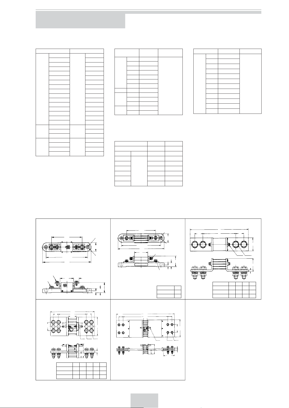
ACCESSORIES
EXTERNAL SHUNT
2215, 2216, 2217
Model Rating
01
02 1.5 A
03 2 A
04 3 A
05 5 A
06 7.5 A
07 10 A
08 15 A
2215
09 20 A
10 30 A
11 50 A
12 75 A
13 100 A
14 150 A
15 200 A
16 300 A
01
2216
02 750 A
03 1000 A
01
02 2000 A
2217
03 3000 A
04 5000 A
Class: Class 0.2 of rated value
Rated voltage drop: 50 mV
50 mV
50 mV
50 mV
1 A
500 A
1500 A
EXTERNAL MULTIPLIER
2224, 2225, 2226, 2228
Model Rating
01 50 V
02 75 V
03 100 V
2224
04 150 V
05 300 V
06 500 V
07 750V
2225 00 1 kV
01 1.5 kV
2226
02 2 kV
03 3 kV
01 5 kV
2228
02 7.5 kV
Accuracy: ±0.5% of rated value
Measuring method: 2224...2 terminal type
2225, 2226, 2228...3 terminal type
Current
Consumption
1 mA
EXTERNAL VT
Model 2267 2268
Rated Burden 15 VA 50 VA
Primary
Secondary
220 V
440 V 2267 02 —
1100 V 2267 03 —
2200 V 2267 04 —
110 V
3300 V 2267 05 2268 01
6600 V — 2268 02
Class: Equivalent to JIS C1731 Class 1.0
Structure: Epoxy mold type
——
2267 01 —
EXTERNAL CT
2255
Model Primary Secondary
01 10 A
02 15 A
03 20 A
04 30 A
05 50 A
06 75 A
2255
07 100 A
(15 VA max.)
08 150 A
09 200 A
10 250 A
11 300 A
12 500 A
Class: Equivalent to JIS C1731 Class 1.0
Structure: Epoxy model type
Dielectric Strength: less than 3450V
OTHER
Shunt lead: 219930-24
5 A
DIMENSIONS FOR ACCESSORIES
2215 (1 to 7.5 A) 2215 (10 to 300 A) 2216 (500 to 1000 A)
M6
M5
110
150±
175
0.4
17.5
45
5.5 dia.
30
12 dia. spot
facing
35.5
14.5
6.5
2217 (1,500 to 3,000 A) 2217 (5,000 A)
270
17032 32
50
Q
M5 M12 14 dia.
C
W
H
D
50
110
150±
175
50
0.4
700
540
50
5.5 dia.
30
12 dia.
M5
H
* M6
6.5
14.5
* 100 to 300 A are M8
Rating H
10 to 100 A 39.5
150 to 300 A 54.5
50
M5 M12 14 dia.
53
110
136
90
200
6
66
66
Rating HPAW
1,000 A 6417027084
(unit: mm)
A
P32
500 A 50
750 A 64
50
60
32
M5 M12
130
230
130
230
6.5
WH
6
*Dashed line is
for 1,500 A
Rating DCHQW
1,500 A 123574—92
2,000 A 12358150
110
3,000 A 205311770
120
29
Page 32

Accessories
2224 (50 to 750 V) 2225 (1 kV) 2226 (1.5, 2 , 3 kV)
3.5 dia.
1k
V
28
±
0.25
35
43
METER
8.5
76
±0.5
96
4.5 dia.
30
1
±
15
180
±
1
(unit: mm)
11
17
7.5
20.5
147 33
64
63
6
5
59.5
204
2228 (5, 7.5 kV) 2255 (10 to 500 A/5 A) 2267 (220 to 3300 V/110 V)
A
80 B
66
l
K
P
t
75
9
50
b
d
A base mounting
position can be
changed by 90˚
horizontally.
110 dia.
uv
96
110
Secondary
terminals M5
1.6
155
140
Fuse
40
62
50
60
120
METER
26
135
180
162
210
108 dia.
11
7
K
Secondary
terminals M5
129
10
100
1.6
82
±
1
26
Rating tdbPBA
10 to 150 A 47251245
200, 250 A 492515
300, 500 A 5114020
170
180
200
2268 (3.3 to 6.6 kV/110 V)
Primary
135
120 dia.
Fuse
208
200
terminals M5
32
6
85
Primary
terminals M5
25
160
135
56
uv
112
130
Secondary
terminals M5
2
80
110
200
168
7
30
Page 33

31
Page 34

32
Page 35

Page 36

Yokogawa Meters & Instruments Corporation
Phone: 81-42-534-1413, Fax: 81-42-534-1426
Yokogawa Corporation of America Phone: 1-770-253-7000, Fax: 1-770-251-2088
Yokogawa Europe B.V. Phone: 31-33-4641000, Fax: 31-88-4641111
Yokogawa Engineering Asia Pte. Ltd. Phone: 65-62419933, Fax: 65-62412606
Subject to change without notice. [Ed: 04/b] Printed in Japan: Mar. 2013/500(KP)
All Rights Reserved. Copyright © 2000, Yokogawa Meter&Instruments Corporation.
 Loading...