

Page 1
User’s
Manual
取扱説明書
2042
携帯用三相電力計
Portable Three-phase Wattmeter
IM 2042-01
2018. 3 7 版
7th Edition: March 2018
Page 2

本器を安全にご使用いただくために
SAFETY PRECAUTIONS
本器を安全にご使用いただくために,ご使用に先だって以下
に記載された警告文,および取扱説明書<本文>を必ずお読
みいただき,注意,使用方法についての内容は必ず守ってく
ださい。
これらの注意 に反したご使用により生じた障害については,
YOKOGAWA は責任と保証を負いかねます。
このマニュアルは製品の一部として重要な内容を含んでいま
す。本器を廃棄するまで,本器を使用するときにすぐご覧に
なれるところに,このマニュアルを大切に保存してください。
The following general safety precautions must be observed
during all phases of operation, service and repair of this
instrument. Failure to comply with these precautions or with
specific WARNINGS given elsewhere in this manual violates
the safety standards of the design, manufacture and intended
use of the instrument.
YOKOGAWA assumes no liability for the customer’s failure to
comply with these requirements.
This manual is part of the product and contains important
information. Store this manual in a safe place close to the
instrument so that you can refer to it immediately.
Keep this manual until you dispose of the instrument.
— i —
IM 2042-01
Page 3
本器および取扱説明書には安全記号 が表示されています。
この安全記号は,人体および機器を保護するために,取扱注意
の警告,取扱説明書や添付資料を必ず読む必要があることを
警告しています。
警 告
感電の恐れがありますので,以下のことを必ず守って
ください。
・ 計器および付属機器を接続する場合は,回路が活線状態で
ないことを確認してから行ってください。
・ 接続端子は,緩みのないように確実に締め付けてください。
・ 通電中は,入力端子およびその他の端子またはプラグ挿入
口等に触れないでください。
・ 通電中は,ケースおよびカバーを開けないでください。
・ 外付変流器と組み合わせて使用する場合,変流器の 1 次側
に通電されている状態で 2 次側をオープンにすると危険電
圧が発生しますので,計器をはずす前に 2 次側を短絡して
ください。
・ 定格電流,定格電圧を超える入力を加えないように注意し
てください。
The safety symbol is shown both on the instrument and
throughout the instruction manual to draw attention to the necessary
safety precautions.
WARNING
To avoid injury or death to p erson nel and d amage to th e
instrument, be sure to comply with the following.
• Make sure that the source voltage is not alive before you
attempt to connect the instrument to the circuit.
• Once you have connected the instrument to the circuit, tighten
the terminals.
• Never touch the terminals or plug holes when operating the
instrument.
• Never open the case or cover when operating the instrument.
• In an application where the instrument is used in combination
with an external current transformer, a hazardous voltage will
develop if the transformer’s secondary stage is open-circuited
with the primary stage electried. Be sure to short-circuit the
secondary stage before removing the instrument from the
transformer.
• Be sure not to exceed the rated current and the rated voltage.
IM 2042-01
— ii —
Page 4

目 次
CONTENTS
本器を安全にご使用いただくために ...................................i
概 要 .............................................................................................. 1
取扱法および使用上の注意 ..................................................... 3
1. 結線方法 ............................................................................ 4
2. 測定レンジの切換 .......................................................... 7
3. 乗数表の使い方 ..............................................................8
4. 自己消費電力の補償 .....................................................9
保 守 .............................................................................................. 1 2
仕 様 .............................................................................................. 1 3
保 証
本器は,厳密な社内検査を経て出荷されておりますが,万一
製造上の不備による故障あるいは輸送中の事故等による故障
の節は,お買上げいただいた販売店または当社販売員にお申
しつけください。
当社製品の保証期間はご納入日より 1 年間です。この間に発
生した故障で,原因が明らかに当社の責任と判定された場合
には無償修理いたします。
SAFETY PRECAUTIONS .................................................. i
INTRODUCTION ............................................................... 1
OPERATING INSTRUCTIONS ......................................... 3
1. Connections .............................................................. 4
2. Range Selection ........................................................ 7
3. Using the Table of Range-multiplier Constants ........ 8
4. Compensation of Wattmeter Power Consumption .... 9
MAINTENANCE ................................................................ 12
SPECIFICATIONS .............................................................. 13
Warranty
The 2042 instruments are shipped only after stringent inhouse inspection. Should the instrument suffer damage that
is attributable to improper manufacture or an accident during
transport, contact the sales representative from which you
purchased the product or your nearest YOKOGAWA sales
ofce.
All products of YOKOGAWA are guaranteed for a period of one
(1) year from the date of delivery.
YOKOGAWA will repair the product in question, free of charge,
if the product fails during the guarantee period for reasons that
are evidently attributable to YOKOGAWA.
— iii —
IM 2042-01
Page 5

概 要
INTRODUCTION
携帯用三相電力計 2042
形電力計で,研究室や工場などにおいて交流の三相三線式の電力,
単相電力を精密に測定する際に用います。
使用可能周波数は,25
は,トートバンド支持方式の空心電流力計
〜 1000 Hz の範囲です。
The 2042 is an electrodynamic, portable three-phase wattmeter with tautband suspension movement. It is designed to measure the electrical power
of three-phase, three-wire circuits in both laboratories and in the eld with
high accuracy. It can also be used to measure single-phase power.
The 2042 can be used for signals with a frequency between 25 Hz and
1000 Hz.
— 1 —
IM 2042-01
Page 6
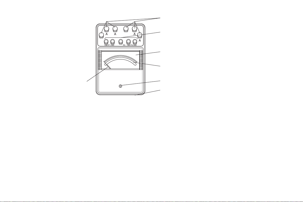
Table of Range-multiplier Constants
電流端子
Current Terminals
指針
Pointer
Fig.1
電圧端子:
電流端子:
乗 数 表:
IM 2042-01
±
±
電圧結線をする端子で,共通端子には “±” の記号が付
けられ他の端子には各定格電圧が記入されています。
電圧コイルとの極性関係を表わすために “±” の記号と
他の 2 端子には各定格電流が記入されています。
計器の側面にはりつけてある表で,単一スケールで読み
取った計器示値に表中の乗数をかけて実際の電力値を
求めるのに使用します。
取扱法の項を参照してください。
電圧端子
Voltage Terminals
目盛板
Dial
ミラー
Mirror
零位調整器
Zero Adjust Screw
乗数表
V oltage Terminals:
These are used for the voltage connection.
The common terminal is marked with the voltage polarity “±”, and
the two other terminals are marked with their respective voltage
ratings.
Current Terminals:
One of the terminals is marked with “±” to show the polarity
relation to the voltage coil, and the two alternative current
terminals are marked with their respective current ratings.
Table of Range-multiplier Constants:
The table is located on the side of the instrument case, and the
actual power value is obtained by multiplying the constant listed in
the table by the indication value on the scale.
Refer to the operational procedure for more information.
— 2 —
Page 7

取扱法および使用上の注意
OPERATING INSTRUCTIONS
1. 計器は,直射日光の当たる場所,外部磁界のある場所,振動の
ある場所,あるいは高温高湿な環境では使用しないでください。
2. 計器は,常に水平位置(標準姿勢)で使用してください。
このとき最も正確な指示が得られます。
3. 多数の計器を並べて使用するときは,でき得る限り離して使う
ようにしてください。
4. 計器の結線に先だち測定範囲,極性等をよく確認し,端子の締
付けは確実に行ってください。また大電流の測定時には,その
接続導線の電流容量にも注意をはらい十分太い線で行ってくだ
さい。
5. 測定に入る前に指針が目盛の零位に一致していることを確かめ
ます。もし一致していなければ零位調整器を左右に回して合わ
せます。ミラーに映った指針の像と指針とが一致する目の位置
で行ってください。ただし,指針の曲がりで零位から外れたも
のは,誤差の原因となりますので,零位調整器で合わせないよ
うにしてください。
6. 計器に,その最大目盛値以上の値をみだりに加えないよう注意
してください。測定値があらかじめ予測できない場合には最も
大きい測定範囲から順次下位に換えて測定してください。
7. 測定の精度を高めるために計器の指示はなるべく最大目盛値か
らその 1/2 の間の目盛で読みとれるような測定範囲の計器を選
びます。
8. 測定中に計器の窓ガラスの表面を乾いた布で強く拭きますと静
電気のため指示が変化することがありますので避けてください。
特に乾燥期にはご注意ください。
表面の汚れは,乾いた布で軽く拭きとってください。
1. Do not use these instruments in a location exposed to direct sunlight, an
external magnetic eld or mechanical vibration or in a high-temperature
highly humid environment.
2. Place the instrument on a fairly level surface.
A horizontal position will give the highest accuracy.
3. When using a number of these instruments in an array, keep them as far
away from each other as possible.
4. Before wiring any of these instruments, carefully check the measuring
ranges and polarities. When wiring, securely fasten the terminals.
When a large current needs to be measured, use wire that is both thick
enough and has sufcient current-carrying capacity.
5. Before measurement, check that the pointer coincides exactly with the
zero scale point. If it does not turn the zero adjust screw provided on
the meter cover until the pointer meets the zero scale point.
Position your eye so that the mirror image of the pointer coincides with
the actual pointer. However, if the pointer is off from the zero scale
point because the pointer is bent, do not adjust using the zero adjust
screw because this will lead to errors.
6. Be careful not to apply an unreasonably large current or high voltage to
the instrument.
7. For the optimum instrument accuracy, select a measuring range such
that the indication may be read in the top half of the scale.
8. Try not to apply too much force when wiping the glass window surface
of the instrument during measurement. Doing so, may result in a
deviation in the indication due to static electricity.
This is especially true when the instrument is used in a dry season.
If the surface is dirty, clean it gently with a dry soft cloth.
— 3 —
IM 2042-01
Page 8

1. 結線方法
Measured power (watt)
= indicator reading × range multiplier
Measured power (watt)
= indicator reading × range multiplier × CT ratio
Measured power (watt)
= indicator reading × range multiplier × VT ratio
Fig. 2-1
Fig. 2-2
Fig. 2-3
Power Source
CT
Load
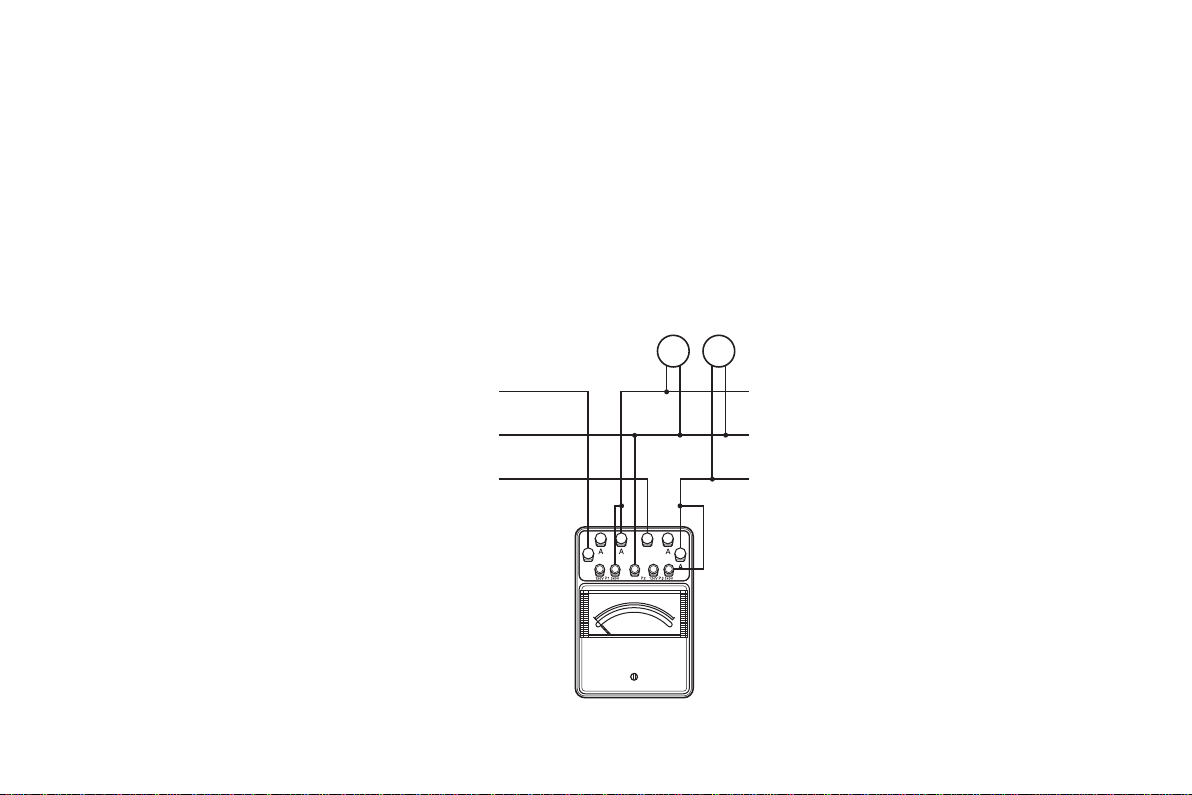
(1) 三相電力測定
Fig. 2-1 のように電圧の “P1” , “P3” を負荷側にして “P1” とR相
の “A”,“P
負荷電力 (Watt) = 計器の読み×乗数
(2) 電流が定格値をこえる場合の三相電力測定
Fig. 2-2 のように電流回路に計器用変流器(CT)を接続します。
負荷電力 (Watt) = 計器の読み×乗数×変流比
(3) 電圧が定格値をこえる場合の三相電力測定
Fig. 2-3 のように電圧回路に計器用変圧器(VT)を接続して測定
します。
負荷電力 (Watt) = 計器の読み×乗数×変圧比
” と T 相の “A” を結線します。
3
1. Connections
1. Three-phase power measurement
As shown in Figure 2-1, connect the “P1” terminal to the R-phase terminal “A”
and the “P
these voltage terminals “P
2. Three-phase power measurement where the current exceeds the rated value
Connect a current transformer (CT) to a current circuit as shown in Figure
2-2.
3. Three-phase power measurement where the voltage exceeds its rated value
Connect a voltage transformer (VT) to a voltage circuit as shown in Figure
2-3.
” terminal to the T-phase terminal “A”, making sure that both of
3
” and “P3” are connected to the load side
1
IM 2042-01
R
電源
S
T
±
負荷
Load
Power Source
±
電源
R
S
T
LK
k
CT
k
±
±
負荷
Load
LK
Power Source
電源
R
S
T
V
U
VT VT
v
u
±
±
負荷
V
U
v
u
— 4 —
Page 9

6600
= 600 kwatt (kW)
負荷電力
Measured power (watt)
= indicator reading × range multiplier ×
VT ratio × CT ratio
Fig. 2-4
Power Source
CT
Load
(4) 電流,電圧ともに定格値をこえる場合の三相電力測定
Fig. 2-4 のように電流回路に変流器,電圧回路に変圧器を接続し
て測定します。
負荷電力 (Watt) = 計器の読み×乗数×変圧比 × 変流比
<計算例>
計器使用レンジ:
乗 数:
計器指示:
変圧比:
変流比:
10
6600/110 V
50/5 A
120 V, 5 A
100
110505
= 600 000 watt (W)
×= 100 × 10 ×
R
電源
S
T
4. Three-phase power measurement where both the voltage and the
current exceed their rated values
Connect a VT to a voltage circuit and a CT to a current circuit as shown in
Figure 2-4.
Example:
Instrument terminals connected:
Range multiplier:
Indicator reading:
VT ratio:
CT ratio:
10
100
6600/110 V
50/5 A
120 V at 5 A
Measured power (watt) = 100 × 10 × (6600/110) × (50/5)
= 600 000 watts (W)
LK
k
= 600 kilowatts (kW)
負荷
CT
LK
k
V
U
V
U
VT VT
v
u
v
u
±
±
— 5 —
IM 2042-01
Page 10

(5) 単相および直流電力測定
Measured power (watt)
= indicator reading × range multiplier × 0.5
Fig. 2-5
Power Source
(+)
(+)
Load
Fig. 2-5 のように結線します。
乗数は
乗数表を 1/2 にして使用してください。
2042
直流使用の場合は外部磁界の影響を極力さけるため Fig. 2-5 結線
の測定電力と Fig. 2-6 結線の測定電力の平均電力が測定電力(負
荷電力)とします。
5. DC or single-phase power measurement
Connect a meter as shown in Figure 2-5.
To minimize the external magnetic field influence on the DC power
measurement, use the mean value of the power levels measured when the
terminals are connected as shown in Figure 2-5 or 2-6.
単相で測定(試験)を行なう場合には,三相測定(試験)
より,値が-0.2~-0.3%(最大値で)低い値になること
もあります。
IM 2042-01
注 記
電源
(–)
±
NOTE
The power level obtained from single-phase power measurements may be 0.2 to 0.3% lower than that of three-phase
power measurements.
負荷
Load
Power Source
電源
(–)
±
±
±
Fig. 2-6
— 6 —
負荷
Page 11

2. 測定レンジの切換
(1) 測定に際し,いずれの場合でも電圧端子は,回路電圧に近いレン
ジを用い,負荷大電流が未知の場合,最初電流測定端子に接続し
電源スイッチを入れます。
電圧,電流レンジとも端子切換で電圧レンジは,2 倍定格比 (2:1),
電流レンジは,5 倍定格比 (5:1) です。
(2) 電流回路が変流器の二次側に接続されている状態でレンジ切換を
行う場合,
変流器に二次巻線短絡鍵があれば,これをまず閉路してレンジ
切換えを行ってください。
二次巻線短絡鍵がない場合には,電源を切るとか,電流端子の接
続を換えるときにとりはずされるべき電流端子の配線をそのまま
にしておいて,その配線の一端を必要とする電流端子に接続して
それから不要の電流端子の配線をはずすようにしてください。
変流器の二次が開路にならぬようご注意ください。
2. Range Selection
(1) For an accurate measurement, use the voltage terminal whose rated
value is closer to the circuit voltage. If the load current is unknown,
connect the circuit to the current terminal rated largest initially.
Then apply power to the circuit.
Both voltage and current ranges are changed by selecting terminals.
The ratio of the voltage ranges is 2:1.
The ratio of current ranges is 5:1.
(2) When using a current transformer, be sure not to open the secondary
circuit of the CT when changing the current range.
If the CT is provided with a switch to short the secondary circuit,
close the circuit using the switch before changing the measuring
range. If such a switch is not provided, you can either switch off the
power source before proceeding with the change or you can follow the
alternative wiring method for changing the range.
In this method, you use another leadwire to connect between the circuit
terminal to which the existing leadwire is connected and the CT current
terminal to be used for the new measuring range. Leave the existing
leadwire connected all during this procedure. Once the new terminal is
connected, you can disconnect the existing leadwire from the original
CT current terminal that will no longer be used.
— 7 —
IM 2042-01
Page 12

3. 乗数表の使い方
負荷電力=計器の読み (Watt) ×乗数 ・・・ 式1
2×定格電流(A)×定格電圧(V)×定格力率(1.0)
全目盛数(120)
乗数= ・・・ 式2
例) 定格電流1/5 A,定格電圧120/240 V 計器
… Eq. 1
Load power = indicator reading × range multiplier
Range multiplier
Eq. 2
number of divisions (120)
計器の側面に貼付けられた説明銘板の乗数表は,120 区分に統一され
た目盛で読み取った値を電力値に換算するときに使用します。
求める電力が式 1 で得られます。
乗数は,式 2 で与えられますが使用電圧,電流レンジに応じて表から
引いてください。
3. Using the Table of Range-multiplier Constants
The multiplier constant table is attached to the side of the instrument, and
is used to obtain the actual measuring power from the reading on the scale.
In other words, the actual power is calculated from equation 1.
The range multipliers depend on the voltage and current range settings and
are calculated from equation 2.
Voltage range
Current range
1 A
5 A
Multiplier constant
120 V
2
10
240 V
4
20
IM 2042-01
— 8 —
2 × rated current (A) × rated voltage (V) × rated power factor (1.0)
=
Example:
Instruments with a rated current of either 1 A or 5 A and a rated
voltage of 120 V or 240 V.
…
Page 13

4. 自己消費電力の補償
Power Source
R
Load
FC
Fig.3-1
計器の指示は,負荷の電力と計器の負荷側に結線されたコイル(電流
コイルまたは電圧コイル)の消費電力との和となりますので,負荷の
電力を精密に測定したい場合や小さい電力計(1 kW 以下)の場合,
計器自身の消費電力を計器の読みから差引かなければなりません。
(1) 電圧コイルが負荷側に結線された場合の補償
・ 電源インピーダンスが低く電圧変動の少ない場合,または比較的
負荷電力の少ない場合は,Fig. 3-1 のように結線し電圧コイルの
損失は負荷を切り離したときの指示値にほぼ等しくなります。
この値を始めの指示値から引けば真の負荷電力が得られます。
4. Compensation of Wattmeter Power Consumption
The value indicated on the wattmeter is the sum of the load power and
the consumed power of the coil (current or voltage coil) connected to the
load side. If high accuracy is desired or the rated power of the wattmeter is
small (less than 1 kW), the power consumed by the coil must be subtracted
from the indicated value.
(1) Compensation when the voltage coil is connected to the load side:
• The connections for a power source with low impedance or for a
relatively small load power are as shown in Fig. 3-1.
The power consumption of the voltage coil in this case is almost the
same as the value indicated on the scale with no load.
Subtract this value from the rst readout to obtain the true load power.
電源
R
S
T
電源
S
負荷
Load
T
Power Source
±
±
P2
±
±
MC
MC
FC
A
P1
負荷
A
P
3
MC: 電圧コイル Voltage Coil
FC: 電流コイル Current Coil
— 9 —
IM 2042-01
Page 14
・ 電源インピーダンスが高い場合や負荷の大きな場合は,内部抵抗
P = W – V
1r1
1r1
2
2
の内部抵抗
P = W – V
1r1
1r1
Fig. 3-2
Power Source
Load
のわかっている電圧計を使用して,Fig. 3-2 の回路と計算式から求
めます。
(— + —) – V (— + —)
1
2
r
1
r
2
P: 負荷電力
W: 電力計の指示電力
V
, V2: 電圧計の指示電圧
1
r: 電力計の電圧回路抵抗
r
, r2: 電圧計r1, r
1
2
R
• If the power source impedance is high or the load power is large, the true
load power value can be obtained by connecting two voltmeters with
known internal resistances as shown in Fig. 3-2, and by performing the
following calculation.
2
(— + —) – V (— + —)
1
2
2
r
1
r
2
P: Load power
W: Power indicated on the wattmeter
V1, V2: Voltages indicated on the voltmeter
r: Voltage circuit resistance of wattmeter
r1, r2: Internal resistances of voltmeters 1 and 2
V
V
1
2
r1r
2
IM 2042-01
電源
S
負荷
T
±
±
r
— 10 —
Page 15

(2) 電流コイルが負荷側の場合の計器損失
Fig. 3-3
Power Source
R
Load
Fig. 3-3 のように電圧コイルを負荷側に結線を変更すると,三相負荷
がほぼ平衡している場合には計器損失を示します。この値をはじめの
指示から引けば,真の負荷電力を求めることができます。
(2) Compensation when the current coil is connected to the load side:
When the current coil is connected to the load side as shown in Fig. 3-3,
the meter will indicate the power consumption of the current coil when the
load is balanced. Subtract this value from the rst readout to obtain the true
load power.
電源
S
負荷
Load
T
Power Source
±
±
R
± ±
A
電源
S
MC MC
T
MC: 電圧コイル Voltage Coil
FC
P1 P2
FC
P
3
A
負荷
FC: 電流コイル Current Coil
— 11 —
IM 2042-01
Page 16

保 守
MAINTENANCE
1. 計器の保管は,直射日光の当らない湿気の少ない場所にしてく
ださい。また,埃りがかからないようにご留意ください。
2. 精度を確保し,常に正しい精度で測定するためにも定期的な校
正をおすすめします。
校正の周期は,計器の使用頻度や使用条件により異なりますが,
3 か月に 1 〜 2 回行えば理想的です。
アフターサービス
正常な動作を示さず修理を要する場合には,
当社または販売代理店へお申しつけください。
1. To ensure good measurements, keep the instrument free of dust,
moisture, and away from direct sunlight.
2. If an overload or excessive shock causes the accuracy of the instrument
to become doubtful, check several scale points and compare these
readings with an instrument which has been properly calibrated.
If the accuracy of the instrument is found to be different from its rating,
readjust the instrument.
NOTE
If any troubles occur in the instrument, contact your nearest
YOKOGAWA Sales office or sales agent.
IM 2042-01
— 12 —
Page 17

仕 様
動作原理 : 電流力計形
指針振れ角 : 約 85°
目盛長: 約 135 mm
目盛区分: 120 区分
定格周波数: 50/60Hz
使用周波数: 2042 01* : DC, 25 〜 1000 Hz
2042 02, 2042 03: DC, 25 〜 1000 Hz
自己加熱の影響: 約 0.25% 以下
交流・直流の差 約 0.1% 以下
温度の影響: 約 0.3%/10℃以下
外部磁界の影響: 400 A/m で約 1.0% 以下
力率の影響: 力率 1.0 から 0.5 変化で 0.5% 以下
許容入力電圧: 定格電圧の約 1.5 倍
許容入力電流: 定格電流の約 2 倍
絶縁試験: 電気回路と外箱間 DC 500 V にて 10 MΩ 以上
電流回路と電圧回路間 DC 500 V にて 5 MΩ 以上
電圧試験: 電気回路と外箱間 AC 2000 V,5 秒間
電流回路と電圧回路間
使用温湿度範囲: 0 〜 40℃,25 〜 80% RH
保存温湿度範囲: − 10 〜+ 50℃,25 〜 80% RH
外形寸法: 約 260 × 180 × 140 mm
質量: 約 3.2 kg
アクセサリ(別売): 携帯用かばん 2292 01
* 受注停止製品
AC 1500 V,5 秒間
SPECIFICATIONS
Operating Principle: Electrodynamics
Deection Angle: Approx. 85°
Scale Length: Approx. 135 mm
Scale Divisions: 120-division
Rated Frequency: 50/60 Hz
Frequency Ranges:
2042 01* : DC, 25 to 1000 Hz
2042 02, 2042 03: DC, 25 to 1000 Hz
Effect of Self Heating:
Difference between Indication DC and AC Measurements:
Effect of Temperatur e:
Effect of External Magnetic Field:
Effect of Power Factor:
Less than 0.5% for a change in power factor from 1.0 to 0.5
Allowable Input Voltage:
Allowable Input Current:
Insulation T est:
Between electrical circuit and case DC 500V / More than 10 MΩ
Between current circuit and voltage circuit DC 500V / More than 5 MΩ
V oltage Test:
Between electrical circuit and case AC 2000V for 5 second
Between current circuit and voltage circuit AC 1500V for 5 seconds
Operating Temperature and Humidity Range:
Storage Temperature and Humidity Range:
Dimensions : Approx. 260 × 180 × 140 (mm)
Weight: approx. 3.2 kg
Optional Accessories: Carrying case model 2292 01
Less than 0.25% of full scale value (approx.)
Less than 0.1% of full scale value (approx.)
Less than 0.3%/10°C (approx.)
Less than 1.0% (approx.) at 400 A/m
Rated Voltage×1.5 (approx.)
Rated Current×2 (approx.)
0 to 40°C, 25 to 80% RH
-10 to 50°C, 25 to 80% RH
— 13 —
* Discontinued product
IM 2042-01
Page 18

定格
※ 電圧レンジ,電流レンジの消費電力の和の2倍が
※ Total volt-ampere loss of the 2042 = [volt-ampere loss of voltage range + volt-ampere loss of current range] × 2.
三相電力計 Three-phase Wattmeter
Rating (Range)
Rated
Rated
Voltage
形名
Model
Current
0.2/1 A
1/5 A
0.2 A
1 A
1 A
2042 01 *
2042 02
5 A
5/25 A
5 A
25 A
2042 03
Power Rating
120 V
48 W
480 W
240 W
480 W
240 W
2.4 kW
1.2 kW
2.4 kW
1.2 kW
12 kW
6 kW
240 V
96 W
Approx.
Internal
Impedance
12000 Ω
24000 Ω
16.35 Ω
0.56 Ω
0.93 Ω
0.034 Ω
0.064 Ω
0.0027 Ω
* 受注停止製品
* Discontinued product
Approx.
Volt-Ampere
Loss
1.2 VA
2.4 VA
0.66 VA
0.56 VA
0.93 VA
0.84 VA
1.72 VA
1.69 VA
2042の概略総合消費電力になります。
IM 2042-01
— 14 —
Page 19

<アクセサリ Accessories>
計器用変流器:0.2級
2262 00 *
measuring ranges, and with through-hole terminals for the 250 A, 300 A, 500 A,
Current Transformer: 0.2%
形名
Model
2241
2242
2244
2243 00 *
注 1. 最高回路電圧
2241: 3450 V
2242: 6900 V
2244 (2243*): 250 V
2. 2241, 2242: 10~100 Aの測定範囲は端子式
250~1500 Aの測定範囲は貫通式
3. 2243*: 0.1級
4. 2244: 電流測定専用,電力測定不可
コード
Code
00
00
00
計器用変圧器:0.2級
Voltage Transformer: 0.2%
形名
Model
2261
2261 02 *
2261 03 *
コード
Code
01 110 V
一次
Primary
10/15/30/50/100/250/300/500/750/1500 A
10/15/30/50/100/250/300/500/750/1500 A
500 A (500 AT)
0.5/0.75/1/1.5/2/3/5/7.5/10/15/20/30/50/75/100 A
Note 1: The maximum line voltages are as follows.
2241: 3450 V
2242: 6900 V
2244 (2243*): 250 V
Note 2: The instruments also have the following characteristics.
2241 and 2242: Equipped with screw terminals for the 10 A, 15 A, 30 A, 50 A and 100 A
750 A and 1500 A measuring ranges.
Note 3: 2243*: Class 0.1 instrument
Note 4: 2244: For current measurements only. Cannot be used for power measurements.
一次
Primary
220/440/2200/3300 V
15/30/50/75 V
100/200/300/500 V
3300/6600 V
二次
Secondary
5 A
5 A
5 A
5 A
二次
Secondary
150 V
150 V
110 V
* 受注停止製品
* Discontinued product
定格負担
Burden
15 VA
15 VA
15 VA
15 VA
定格負担
Burden
15 VA
15 VA
15 VA
— 15 —
IM 2042-01
Page 20

Printed in China
 Loading...