

Yellow Jacket 40812 Operating Manual
YELLOW JACKET
Refrigeration System Analyzer
Users Manual
UPC# 40812, 40813 and 40815
(Versions 1.06 and higher)
Note: These instructions do not cover the manifold
attached to the instrument.
®

Table of Contents
Chapter Title Pg.
1 Before You Start
Contact and Safety Information
2 Getting Acquainted
Turning the Instrument On
and Off
Battery Considerations
Keyboard Keys
Understanding the Displays
Using the Temperature and
Vacuum Sensors
3 Getting the Job Done
Temperature and Pressure Mode
Vacuum Mode
Vacuum Sensor Calibration
4 Data Logging
Begin Logging
Playback and USB Functionality
Erase Files
5 Settings
Refrigerant Type
Temperature Unit
Elevation
Auto Vacuum Gauge
Power Saving Mode
Auto Power Off
Battery Type
Graph Type
Time Format
Time and Date
Refrigerant Favorites
Zero Pressure
Exiting the Set-Up Display
Settings Shortcut
6 Maintenance
General Maintenance
Replacing the Batteries
Spare Parts
Software Updates
Further Assistance
7 Specications
Safety
2
Chapter Title Pg.
3
3
4
4
Features and Specications 15
Instrumentation Specications 16
Warranty Policy
List of Tables
4
5
6
7
7
7
9
10
10
10
11
11
11
11
12
12
12
12
12
12
12
12
12
12
13
13
13
13
13
14
14
14
15
15
15
Table Title Pg.
1-1 Safety Information
1-2 Symbols
2-1 Key Functions
6-1 Spare Parts
List of Figures
Table Title Pg.
2-1 Menu Display
2-2 Battery Power Symbol
2-3 Low Battery Pop-up Message
2-4 Menu Display
2-5 System Analyzer Display
2-6 P/T Chart Display
2-7 Vacuum Gauge Display
2-8 Data Logging Start-up Display
2-9 Set-Up Display
2-10 Sensor Connections
2-11 Sensors without Boots
2-12 Sensors with Boots
3-1 First System Analyzer Display
3-2 2nd System Analyzer Display
3-3 3rd System Analyzer Display
3-4 Vacuum Gauge Display
3-5 Sensor Calibration Number
4-1 Data Logging Menu
4-2 Data Logging Start-Up Screen
4-3 Data Log Files
5-1 (a, b) Set-up Displays
5-2 Time & Date Setting Screen
5-3 Refrigerant Favorites Set-up
5-4 Refrigerant Favorites Screen
5-5 Settings Shortcut
5-6 Battery Access
5-7 Battery Servicing
16
3
4
5
14
4
5
5
6
6
6
6
6
6
7
7
7
8
8
9
9
10
10
10
11
11
12
12
13
13
14
14
Chapter 1
Before You Start
Contacting Ritchie
To order accessories, receive assistance, or
locate the nearest YELLOW JACKET distributor.
Corporate Ofce and Mailing Address:
Ritchie Engineering Co, Inc.
YELLOW JACKET Products Division
10950 Hampshire Avenue South
Bloomington, MN 55438-2623 U.S.A.
Phone: (952) 943-1300 or (800) 769-8370
Fax: (800) 769-8370
E-mail: custserv@yellowjacket.com
www.yellowjacket.com
Safety Information
Use the instrument only as specied in this
manual. Otherwise, the protection provided by
the instrument may be impaired. Refer to safety
information in Table 1-1.
A Warning identies conditions and actions that
pose hazards to the user. A Caution identies
conditions and actions that may damage the
instrument or the equipment under test.
Table 1-1. Safety Information
Warning
To avoid personal injury or death, follow these
guidelines:
●
Most governments and legal authorities require that HVAC technicians be trained and
certied in the safe and proper operation of
HVAC tools, such as this instrument. Since
this tool may be connected to many types of
equipment through a limitless combination
of hoses and ttings, proper training is the
most important element of using this tool
safely.
●
Read the entire Users Manual before using
the instrument.
●
Use the instrument only as described in the
Users Manual, otherwise the protection provided by the equipment may be impaired.
Do not use the instrument if it is damaged.
●
Before you use the instrument, inspect the
case. Look for cracks or loose components.
Table 1-1. Safety Information
Warning
●
The instrument contains no internal userserviceable parts other than batteries that
may be accessed through the battery door.
Do not open the instrument other than opening the battery door. Have the instrument
serviced only by Ritchie Engineering Co. or
authorized service centers.
●
Do not use the instrument if it operates abnormally. Protection may be impaired. When
in doubt, have the instrument serviced.
●
Refer to warnings supplied with batteries
acquired for use in this instrument. If the batteries are not supplied with warnings, obtain
them from the manufacturer or supplier.
Do not operate the instrument or service bat-
●
teries around explosive gas, vapor, or dust.
●
Various refrigerants have been intentionally
excluded for very signicant safety reasons.
Never use refrigerants in this instrument that
are not listed in the Set-up menu.
●
The refrigerant database in this unit may
include refrigerants classied as ammable.
If such refrigerants are selected, the operator
may need additional certications and/or
training. Consult your government and legal
authority and comply fully with all requirements.
●
Always wear eye and skin protection when
working with refrigerants. Escaping refrigerant vapors will present a freezing danger.
Do not direct refrigerant vapors venting from
hoses towards the skin.
Maximum Working Pressure: High Side: 700
●
psia (4.83 MPa)
Maximum Working Pressure: Low Side: 350
●
psia (2.41 MPa)
●
Because this instrument allows for various
inputs including electrical and mechanical,
care must be taken to observe any ways that
an electrical shock hazard could develop.
Example: Wet or humid conditions, along
with a damaged thermocouple or vacuum
sensor, could allow an electrical path across
the instrument and over wet hoses. Keep all
interconnected equipment clean, organized,
and in proper condition. Do not use the in-
strument if you are not qualied to recognize
potential electrical faults.
cont. next page.......
3
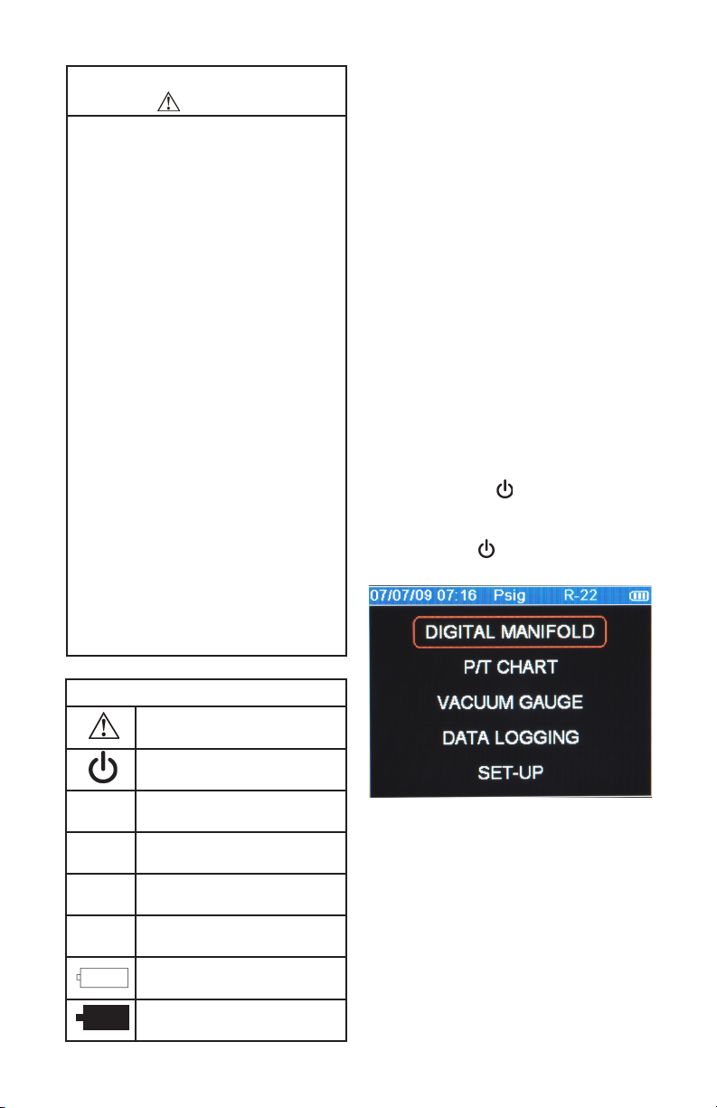
Table 1-1. Safety Information
Caution
To avoid damage to equipment, follow these
guidelines:
Do not allow pressures beyond the speci-
●
cations listed in this manual.
●
Be aware that internal pressures can
change unintentionally when equipment is
stored with pressure in the system during
temperature changes. If sub-cooled liquid
refrigerant is trapped in a hose or manifold
with no room for expansion, it may result in
dramatic pressure variations with seemingly
small temperature changes. Pressures can
reach high enough levels to cause damage to the instrument’s internal pressure
transducers. Release liquid refrigerant from
the hoses and manifold when disconnecting
from a system.
Refer to cautions supplied with batteries
●
acquired for use in this instrument.
Do not attempt to introduce liquid or
●
samples heavily laden with oil into the
instrument.
●
Read and observe instructions and speci-
cations related to the batteries used in this
instrument that may cause damage to it.
Do not use this instrument on systems
●
containing leak sealing chemicals. These
leak sealants can collect and harden in the
instrument, causing permanent damage.
Chapter 2
Getting Acquainted
Introduction
This instrument will clearly and accurately report
critical information needed to properly service refrigeration and air-conditioning equipment. With its
many features, time can be saved and the quality
of service can be veried through data reports for
customer satisfaction. Some of the most signi-
cant features include:
●
High accuracy and resolution
●
Very fast and sensitive leak detection
●
Robust temperature compensation with fault
detection
●
Data logging and downloading for reporting and
analysis
●
High durability and weather-resistance
Note that these instructions do not cover the
manifold attached to the instrument.
Turning the Instrument On
and Off
Press and release the key to turn unit on. After
the logo appears briey, the instrument will present the main menu.
Press and hold the key (~two seconds) to turn
unit off.
4
T1
T2
REC
||><||
Table 1-2 Symbols
Important information
Power On/Off
Temperature 1
Temperature 2
Indicates that the instrument is
recording readings (data logging)
Indicates page-by-page scrolling
mode (during data log playback)
Battery
Battery connector orientation
Figure 2-1. Menu Display
Battery Considerations
The instrument uses eight AA batteries. The
user may select batteries of the following types:
Alkaline, AA-Lithium, Ni-MH, Ni-Cd, Li-Pol, Li-Ion
from the Setup menu (see Chapter 5). Do not mix
battery types, including rating (i.e., do not mix four
Ni-MH rated at 1600mAh with four Ni-MH rated
at 1800mAh). Also, each battery in a set of eight
must be at the same power state, preferably fully
charged. The battery life indicator is only accurate
when the correct battery type is selected in the
SET-UP menu.
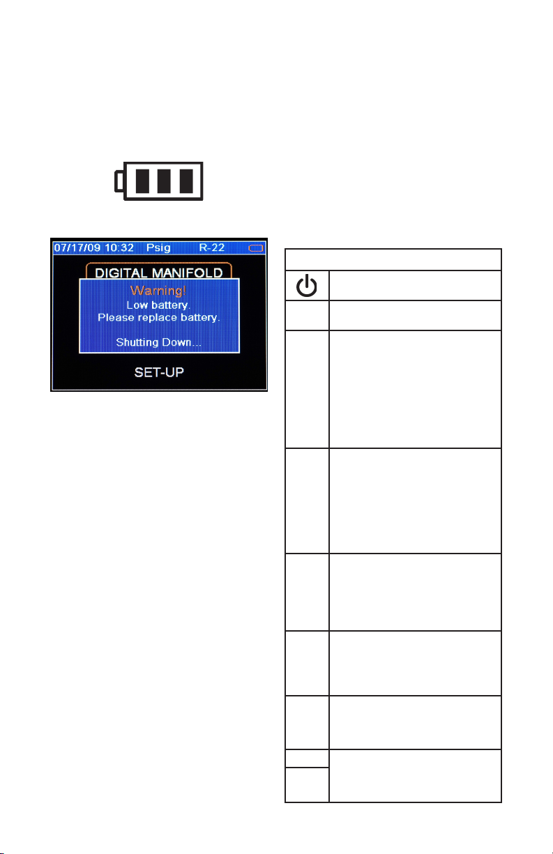
The illustration below shows three bars that indicate a fresh or well-charged battery pack. When
the battery weakens, the bars will disappear oneby-one as the battery power decays. When one
bar remains, the symbol will turn yellow. When all
bars are gone, the batteries are nearly dead and
the symbol will turn red. The unit will briey show
a pop-up message just before the unit stores all
data and then automatically shuts off.
Figure 2-2. Battery Power Symbol
Figure 2-3. Low Battery Pop-Up Message
Automatic Power Off
The instrument may automatically turn off after
a period of time. The default is one hour. The
user may select other settings from ten minutes
to four hours from the Setup menu (see Chapter
5). The user may also disable this feature. The
Auto Power Off time limit is automatically disabled
during data logging and is automatically restored
once data logging has terminated.
Power Saving Mode
The display backlight will fade, darkening the
display to save battery life if a key has not been
pressed for a set period of time. While in Power
Saving Mode, pressing any key turns the display
backlight back to full brightness. Note that
backlighting is independent from the display
brightness and contrast settings (see Chapter 5)
which do not affect battery life.
The Power Saving Mode is preset to 10 minutes.
From the Setup menu (see Chapter 5), you can
specify settings from 30 seconds to 60 minutes.
Low Battery Conditions
The unit will attempt to store all logged data if
low battery power is detected. Once the data is
stored, unit will turn off.
Maximizing Battery Life
Battery life decays fastest when the DIGITAL
MANIFOLD display is selected, the vacuum sensor is attached, and the backlight is on. Battery
life during data logging is maximized by using
high-performance batteries, detaching the vacuum
sensor (if not in use), and a short Power Saving
Mode time setting is selected.
Keyboard Keys
Note that pressing a key that has not been
assigned to a function will result in three, short
beeps.
Table 2-1. Key Functions
Power On/Off (see Chapter 2, Turning the Instrument On and Off).
Menu Accesses menu of instrument
functions.
Enter Accepts selected functions and
values.
This key will also toggle the instrument data display modes. See
Chapter 3.
During playback of logged data,
toggles between point-by-point and
page-by-page scrolling.
Clear A single press clears the chart set
point. (See Figure 3-1, item 11)
Press and hold to clear ‘Min.’ and
‘Max.’ values. (See Figure 3-1,
item 5)
Resets vacuum timer to 0:00:00.
(See Chapter 3)
Hold Freezes the data display at the
moment the key is depressed when
data is being displayed. A second
key press will return the display to
the normal, dynamic mode (not accessible during data logging).
Chart
Toggles time resolution to display
Time
more or less of the data acquisition
event, enhancing a user’s ability to
see signicant events (not accessible
during data logging).
Chart
Toggles pressure resolution to t
Pres-
analog pressure data within the
sure
display, enhancing a user’s ability to
see signicant events.
Up/Left Assists in selection of values and
data points depending on the func-
Down/
tion feature involved (not accessible
Right
during data logging).
5
 Loading...