

Page 1
YASKAWA AC Drive V1000
Compact Vector Control Drive
Quick Start Guide
Type: CIMR-VA , CIMR-VT
Models:
To properly use the product, read this manual thoroughly
and retain for easy reference, inspection, and maintenance.
Ensure the end user receives this manual.
200 V Class, Three-Phase Input: 0.1 to 18.5 kW
200 V Class, Single-Phase Input: 0.1 to 3.7 kW
400 V Class, Three-Phase Input: 0.2 to 18.5 kW
Start-Up Programming
Receiving
Mechanical
Installation
Electrical
Installation
& Operation
1
2
3
4
MANUAL NO. TOEP C710606 12B
Troubleshooting
Specifications
Parameter List
Standards
Compliance
5
6
7
8
Page 2

2 YASKAWA ELECTRIC TOEP C710606 12B YASKAWA AC Drive V1000 Quick Start Guide
Page 3

Table of
Contents
i. PREFACE & GENERAL SAFETY .................................. 7
i.1 Preface. . . . . . . . . . . . . . . . . . . . . . . . . . . . . . . . . . . . 8
Applicable Documentation . . . . . . . . . . . . . . . . . . . . . . . . . . 8
i.2 General Safety . . . . . . . . . . . . . . . . . . . . . . . . . . . . . 9
Supplemental Safety Information . . . . . . . . . . . . . . . . . . . . .9
Safety Messages . . . . . . . . . . . . . . . . . . . . . . . . . . . . . . . . 11
Drive Label Warnings . . . . . . . . . . . . . . . . . . . . . . . . . . . . .14
1. RECEIVING ................................................................... 15
1.1 Model Number and Nameplate Check . . . . . . . . . 16
Nameplate . . . . . . . . . . . . . . . . . . . . . . . . . . . . . . . . . . . . . 16
2. MECHANICAL INSTALLATION ................................... 19
2.1 Mechanical Installation . . . . . . . . . . . . . . . . . . . . . 20
Installation Environment . . . . . . . . . . . . . . . . . . . . . . . . . . .20
Installation Orientation and Spacing . . . . . . . . . . . . . . . . . .21
Exterior and Mounting Dimensions . . . . . . . . . . . . . . . . . . .23
YASKAWA ELECTRIC TOEP C710606 12B YASKAWA AC Drive V1000 Quick Start Guide 3
Page 4

3. ELECTRICAL INSTALLATION..................................... 29
3.1 Standard Connection Diagram . . . . . . . . . . . . . . . 30
3.2 Main Circuit Wiring . . . . . . . . . . . . . . . . . . . . . . . . 33
Main Circuit Terminal Functions . . . . . . . . . . . . . . . . . . . . . 33
Wire Gauges and Tightening Torque . . . . . . . . . . . . . . . . . 33
Main Circuit Terminal Power Supply and Motor Wiring . . . 36
Control Circuit Terminal Block Functions . . . . . . . . . . . . . .38
Removable Terminal Block Configuration . . . . . . . . . . . . . 41
Wiring Procedure . . . . . . . . . . . . . . . . . . . . . . . . . . . . . . . . 43
3.3 I/O Connections . . . . . . . . . . . . . . . . . . . . . . . . . . . 45
Sinking/Sourcing Mode Switch . . . . . . . . . . . . . . . . . . . . . .45
3.4 Main Frequency Reference . . . . . . . . . . . . . . . . . . 47
Terminal A2 Switch . . . . . . . . . . . . . . . . . . . . . . . . . . . . . .47
3.5 Wiring Checklist. . . . . . . . . . . . . . . . . . . . . . . . . . . 49
4. START-UP PROGRAMMING & OPERATION ............. 51
4.1 Using the Digital LED Operator . . . . . . . . . . . . . . 52
Keys, Displays, and LEDs . . . . . . . . . . . . . . . . . . . . . . . . . 52
LED Screen Displays . . . . . . . . . . . . . . . . . . . . . . . . . . . . .54
LO/RE LED and RUN LED Indications . . . . . . . . . . . . . . . . 54
Menu Structure for Digital LED Operator . . . . . . . . . . . . . . 55
4.2 The Drive and Programming Modes . . . . . . . . . . 56
Changing Parameter Settings or Values . . . . . . . . . . . . . .56
Switching Between LOCAL and REMOTE . . . . . . . . . . . . . 57
Parameters Available in the Setup Group . . . . . . . . . . . . . 58
4.3 Start-up Flowcharts . . . . . . . . . . . . . . . . . . . . . . . . 59
Flowchart A: Basic Start-Up and Motor Tuning . . . . . . . . . 59
Subchart A1: Simple Motor Set-Up with Energy Savings
or Speed Search using V/f Mode . . . . . . . . . . . . . . . . . . . . 61
Subchart A2: High Performance Operation Using
Open Loop Vector Motor Control . . . . . . . . . . . . . . . . . . . . 62
4 YASKAWA ELECTRIC TOEP C710606 12B YASKAWA AC Drive V1000 Quick Start Guide
Page 5

Subchart A3: Operation with Permanent Magnet Motors . 63
4.4 Application Presets . . . . . . . . . . . . . . . . . . . . . . . . 64
Application Preset Function (APPL) . . . . . . . . . . . . . . . . . 64
Application Presets: A1-06 . . . . . . . . . . . . . . . . . . . . . . . . 64
4.5 Basic Drive Setup Adjustments. . . . . . . . . . . . . . . 66
Control Mode Selection: A1-02 . . . . . . . . . . . . . . . . . . . . . 66
Initialize Parameter Values: A1-03 . . . . . . . . . . . . . . . . . . 66
Frequency Reference Source: b1-01 . . . . . . . . . . . . . . . . 67
Run Command Input Selection: b1-02 . . . . . . . . . . . . . . . 69
Drive Duty Mode and Carrier Frequency Selection:
C6-01 and C6-02 . . . . . . . . . . . . . . . . . . . . . . . . . . . . . . . 71
Drive Input Voltage Setting: E1-01 . . . . . . . . . . . . . . . . . . 72
4.6 Test Run. . . . . . . . . . . . . . . . . . . . . . . . . . . . . . . . . . 73
Powering Up the Drive and Operation Status Display . . . 73
Auto-Tuning . . . . . . . . . . . . . . . . . . . . . . . . . . . . . . . . . . . 73
Operating with the Load Connected . . . . . . . . . . . . . . . . . 78
4.7 Test Run Checklist . . . . . . . . . . . . . . . . . . . . . . . . . 79
5. TROUBLESHOOTING .................................................. 81
5.1 Drive Alarms, Faults, and Errors . . . . . . . . . . . . . . 82
Types of Alarms, Faults, and Errors . . . . . . . . . . . . . . . . . 82
5.2 Fault Detection . . . . . . . . . . . . . . . . . . . . . . . . . . . . 83
Fault Displays, Causes, and Possible Solutions . . . . . . . . 83
5.3 Alarm Detection . . . . . . . . . . . . . . . . . . . . . . . . . . . 96
Alarm Codes, Causes, and Possible Solutions . . . . . . . . . 96
5.4 Operator Programming Errors. . . . . . . . . . . . . . . . 99
oPE Codes, Causes, and Possible Solutions . . . . . . . . . . 99
5.5 Auto-Tuning Fault Detection . . . . . . . . . . . . . . . . 100
Auto-Tuning Codes, Causes, and Possible Solutions . . 100
5.6 Diagnosing and Resetting Faults . . . . . . . . . . . .103
Fault Reset Methods . . . . . . . . . . . . . . . . . . . . . . . . . . . . 103
YASKAWA ELECTRIC TOEP C710606 12B YASKAWA AC Drive V1000 Quick Start Guide 5
Page 6

6. SPECIFICATIONS....................................................... 105
6.1 Heavy Duty and Normal Duty Ratings . . . . . . . . 106
6.2 Single/Three-Phase 200 V Class Drive. . . . . . . . 107
6.3 Three-Phase 400 V Class Drives . . . . . . . . . . . . 110
7. PARAMETER LIST ..................................................... 113
7.1 Parameter Table . . . . . . . . . . . . . . . . . . . . . . . . . . 114
8. STANDARDS COMPLIANCE ..................................... 143
8.1 European Standards . . . . . . . . . . . . . . . . . . . . . . 144
CE Low Voltage Directive Compliance . . . . . . . . . . . . . . . 144
EMC Guidelines Compliance . . . . . . . . . . . . . . . . . . . . . . 146
8.2 UL Standards . . . . . . . . . . . . . . . . . . . . . . . . . . . . 151
UL Standards Compliance . . . . . . . . . . . . . . . . . . . . . . . . 151
Drive Motor Overload Protection . . . . . . . . . . . . . . . . . . . 154
8.3 Safe Disable Input Precautions . . . . . . . . . . . . . 156
Safe Disable Function Description . . . . . . . . . . . . . . . . . .156
Installation . . . . . . . . . . . . . . . . . . . . . . . . . . . . . . . . . . . .156
6 YASKAWA ELECTRIC TOEP C710606 12B YASKAWA AC Drive V1000 Quick Start Guide
Page 7

i
Preface &
General Safety
This section provides safety messages pertinent to this product,
that, if not heeded, may result in fatality, personal injury, or
equipment damage. Yaskawa is not responsible for the
consequences of ignoring these instructions.
I.1 PREFACE . . . . . . . . . . . . . . . . . . . . . . . . . . . . . . . . . . . . . . .8
I.2 GENERAL SAFETY. . . . . . . . . . . . . . . . . . . . . . . . . . . . . . . . 9
YASKAWA ELECTRIC TOEP C710606 12B YASKAWA AC Drive V1000 Quick Start Guide
7
Page 8
i.1 Preface
i.1 Preface
This manual is designed to ensure correct and suitable application of variable V1000-Series
Inverters. Read this manual before attempting to install, operate, maintain, or inspect an
inverter and keep it in a safe, convenient location for future reference. Understand all
precautions and safety information before attempting application.
◆ Applicable Documentation
The following manuals are available for V1000 series drives:
V1000 Series AC Drive Installation & Start-Up Manual
Read this manual first.
This manual describes installation, wiring, operation procedures, functions,
STOP
V1000
ᵄᢙᜰ
ᱜォㅒォㆬᛯ
ജᵄᢙ
ജ㔚ᵹ
ജ㔚
ࡕ࠾࠲
ࡌࡈࠔࠗ
࠶࠻ࠕ࠶ࡊ
ࡄࡔ࠲⸳ቯ
ࠝ࠻࠴ࡘ࠾ࡦࠣ
ߌ߇㧚ᗵ㔚ߩ߅ߘࠇ߇ࠅ߹ߔޕ
ෂޓ㒾
ᝪ߃ઃߌޔㆇォߩ೨ߦߪᔅߕขᛒ⺑ᦠࠍ⺒ߎߣޕ
ㅢ㔚߅ࠃ߮㔚Ḯㆤᢿᓟ
ಽએౝߪࡈࡠࡦ࠻ࠞࡃࠍ
5
ᄖߐߥߎߣޕ
⚖ࠗࡦࡃ࠲ߩ႐วߪޔ㔚Ḯߩᕈὐ߇ធ
400V
ߐࠇߡࠆߎߣࠍ⏕ߔࠆߎߣޕ㧔ޓޓኻᔕ㧕
(Hz)
(Hz)
(A)
(V)
troubleshooting, maintenance, and inspections to perform before operation.
V1000 Series AC Drive Technical Manual
Read this manual for detailed information about parameter usage. Contact a
Yaskawa representative to order this manual.
V1000 Series AC Drive Quick Start Guide
This guide is packaged together with the product. It contains basic
information required to install and wire the drive. This guide provides basic
programming and simple set-up and adjustment. Refere to the V1000
Technical Manual for complete descriptions of drive features and functions.
8 YASKAWA ELECTRIC TOEP C710606 12B YASKAWA AC Drive V1000 Quick Start Guide
Page 9
i.2 General Safety
i.2 General Safety
◆ Supplemental Safety Information
General Precautions
• The diagrams in this manual may be indicated without covers or safety shields to show details.
Restore covers or shields before operating the drive and run the drive according to the instructions
described in this manual.
• Any illustrations, photographs, or examples used in this manual are provided as examples only and
may not apply to all products to which this manual is applicable.
• The products and specifications described in this manual or the content and presentation of the
manual may be changed without notice to improve the product and/or the manual.
• When ordering a new copy of the manual due to damage or loss, contact your Yaskawa
representative or the nearest Yaskawa sales office and provide the manual number shown on the
front cover.
• If nameplate becomes worn or damaged, order a replacement from your Yaskawa representative or
the nearest Yaskawa sales office.
WARNING
Read and understand this manual before installing, operating or servicing
this drive. The drive must be installed according to this manual and local
codes.
The following conventions are used to indicate safety messages in this
manual. Failure to heed these messages could result in serious or possibly
even fatal injury or damage to the products or to related equipment and
systems.
t\
Preface & General Safety
i
DANGER
Indicates a hazardous situation, which, if not avoided, will result in
death or serious injury.
YASKAWA ELECTRIC TOEP C710606 12B YASKAWA AC Drive V1000 Quick Start Guide 9
Page 10
i.2 General Safety
WARNING
Indicates a hazardous situation, which, if not avoided, could result in
death or serious injury.
WARNING! will also be indicated by a bold key word embedded in the text followed by an italicized safety
message.
CAUTION
Indicates a hazardous situation, which, if not avoided, could result in
minor or moderate injury.
CAUTION! will also be indicated by a bold key word embedded in the text followed by an italicized safety
message.
NOTICE
Indicates a property damage message.
NOTICE: will also be indicated by a bold key word embedded in the text followed by an italicized safety
message.
10 YASKAWA ELECTRIC TOEP C710606 12B YASKAWA AC Drive V1000 Quick Start Guide
Page 11
◆ Safety Messages
Heed the safety messages in this manual.
Failure to comply will result in death or serious injury.
The operating company is responsible for any injuries or equipment
damage resulting from failure to heed the warnings in this manual.
Do not connect or disconnect wiring while the power is on.
Failure to comply will result in death or serious injury.
Before servicing, disconnect all power to the equipment. The internal
capacitor remains charged even after the power supply is turned off. The
charge indicator LED will extinguish when the DC bus voltage is below 50
Vdc. To prevent electric shock, wait at least five minutes after all indicators
are OFF and measure the DC bus voltage level to confirm safe level.
DANGER
Electrical Shock Hazard
WARNING
t\
i.2 General Safety
Preface & General Safety
i
Sudden Movement Hazard
System may start unexpectedly upon application of power, resulting in
death or serious injury.
Clear all personnel from the drive, motor and machine area before applying
power. Secure covers, couplings, shaft keys and machine loads before
applying power to the drive.
When using DriveWorksEZ to create custom programming, the drive
I/O terminal functions change from factory settings and the drive will
not perform as outlined in this manual.
Unpredictable equipment operation may result in death or serious injury.
Take special note of custom I/O programming in the drive before
attempting to operate equipment.
YASKAWA ELECTRIC TOEP C710606 12B YASKAWA AC Drive V1000 Quick Start Guide 11
Page 12
i.2 General Safety
Do not attempt to modify or alter the drive in any way not explained in
this manual.
Failure to comply could result in death or serious injury.
Yaskawa is not responsible for any modification of the product made by the
user. This product must not be modified.
Do not allow unqualified personnel to use equipment.
Failure to comply could result in death or serious injury.
Maintenance, inspection, and replacement of parts must be performed only
by authorized personnel familiar with installation, adjustment and
maintenance of AC drives.
Do not remove covers or touch circuit boards while the power is on.
Failure to comply could result in death or serious injury.
Do not use an improper voltage source.
Failure to comply could result in death or serious injury by fire.
Verify that the rated voltage of the drive matches the voltage of the
incoming power supply before applying power.
WARNING
Electrical Shock Hazard
Fire Hazard
CAUTION
Crush Hazard
Do not carry the drive by the front cover.
Failure to comply may result in minor or moderate injury from the main
body of the drive falling.
12 YASKAWA ELECTRIC TOEP C710606 12B YASKAWA AC Drive V1000 Quick Start Guide
Page 13

i.2 General Safety
NOTICE
Observe proper electrostatic discharge procedures (ESD) when
handling the drive and circuit boards.
Failure to comply may result in ESD damage to the drive circuitry.
Never connect or disconnect the motor from the drive while the drive
is outputting voltage.
Improper equipment sequencing could result in damage to the drive.
Do not perform a withstand voltage test on any part of the drive.
Failure to comply could result in damage to the sensitive devices within the
drive.
Do not operate damaged equipment.
Failure to comply could result in further damage to the equipment.
Do not connect or operate any equipment with visible damage or missing
parts.
Install adequate branch circuit short circuit protection per applicable
codes.
Failure to comply could result in damage to the drive.
The drive is suitable for circuits capable of delivering not more than 30,000
RMS symmetrical Amperes, 240 Vac maximum
(200V Class) and 480 Vac maximum (400V Class).
t\
Preface & General Safety
i
Do not expose the drive to halogen group disinfectants.
Failure to comply may cause damage to the electrical components in the
drive.
Do not pack the drive in wooden materials that have been fumigated or
sterilized.
Do not sterilize the entire package after the product is packed.
YASKAWA ELECTRIC TOEP C710606 12B YASKAWA AC Drive V1000 Quick Start Guide 13
Page 14
i.2 General Safety
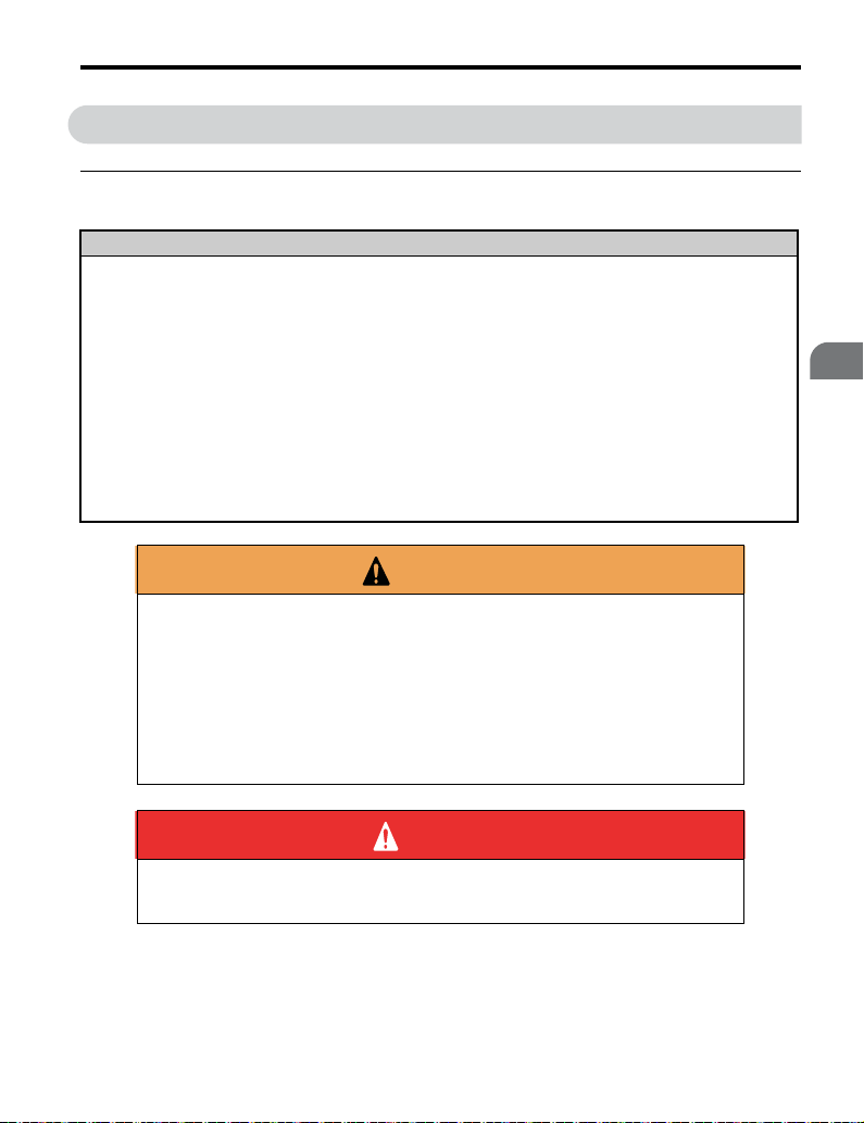
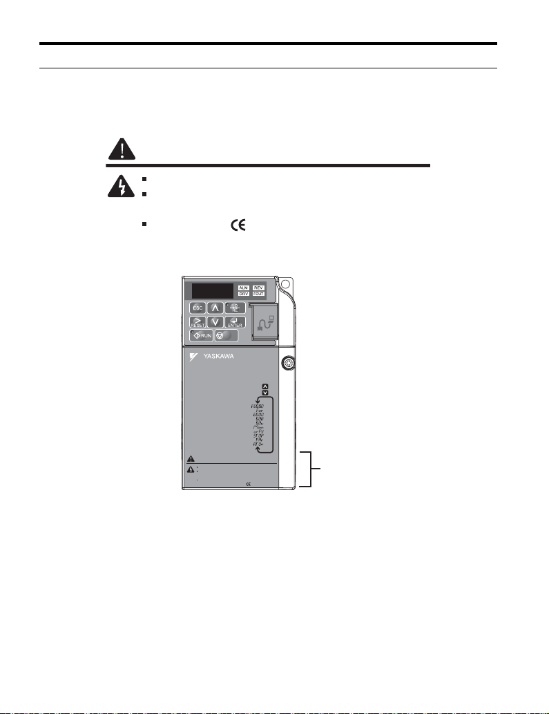
◆ Drive Label Warnings
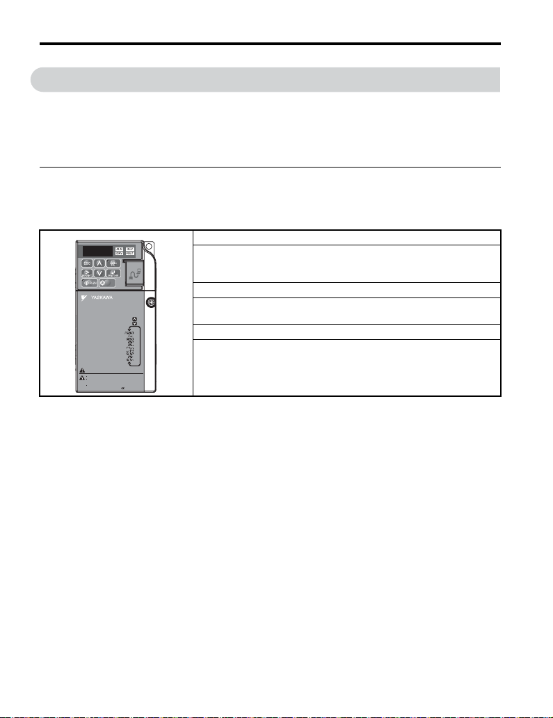
Always heed the warning information listed in Figure i.1 in the position shown in
Figure i.2.
Figure i.1
Figure i.2
WARNING
Risk of electric shock.
Read manual before installing.
Wait 5 minutes for capacitor discharge after
disconnecting power supply.
To conform to requirements, make sure
to ground the supply neutral for 400V class.
Figure i.1 Warning Information
STOP
V1000
(Hz)
ᵄᢙᜰ
ᱜォㅒォㆬᛯ
(Hz)
ജᵄᢙ
(A)
ജ㔚ᵹ
(V)
ജ㔚
ࡕ࠾࠲
ࡌࡈࠔࠗ
࠶࠻ࠕ࠶ࡊ
ࡄࡔ࠲⸳ቯ
ࠝ࠻࠴ࡘ࠾ࡦࠣ
ߌ߇㧚ᗵ㔚ߩ߅ߘࠇ߇ࠅ߹ߔޕ
ෂޓ㒾
ᝪ߃ઃߌޔㆇォߩ೨ߦߪᔅߕขᛒ⺑ᦠࠍ⺒ߎߣޕ
ಽએౝߪࡈࡠࡦ࠻ࠞࡃࠍ
ㅢ㔚߅ࠃ߮㔚Ḯㆤᢿᓟ
5
ᄖߐߥߎߣޕ
⚖ࠗࡦࡃ࠲ߩ႐วߪޔ㔚Ḯߩᕈὐ߇ធ
400V
ߐࠇߡࠆߎߣࠍ⏕ߔࠆߎߣޕ㧔ޓޓኻᔕ㧕
Figure i.2 Warning Information Position
Warning
Display
14 YASKAWA ELECTRIC TOEP C710606 12B YASKAWA AC Drive V1000 Quick Start Guide
Page 15

1
Receiving
This chapter describes the proper inspections to perform after
receiving the drive and illustrates the different enclosure types
and components.
1.1 MODEL NUMBER AND NAMEPLATE CHECK. . . . . . . . . 16
YASKAWA ELECTRIC TOEP C710606 12B YASKAWA AC Drive V1000 Quick Start Guide
15
Page 16
1.1 Model Number and Nameplate Check
++
RoHS
1.1 Model Number and Nameplate Check
Please perform the following tasks after receiving the drive:
• Inspect the drive for damage.
If the drive appears damaged upon receipt, contact the shipper immediately.
• Verify receipt of the correct model by checking the information on the nameplate.
• If you have received the wrong model or the drive does not function properly, contact
your supplier.
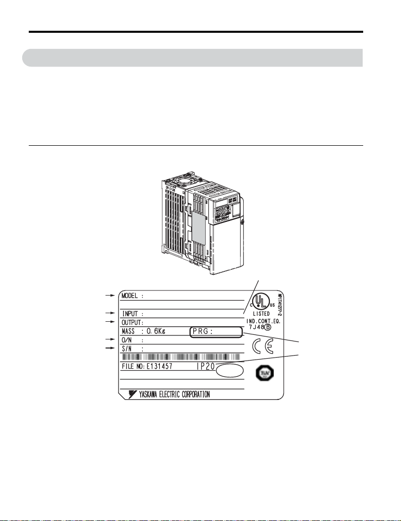
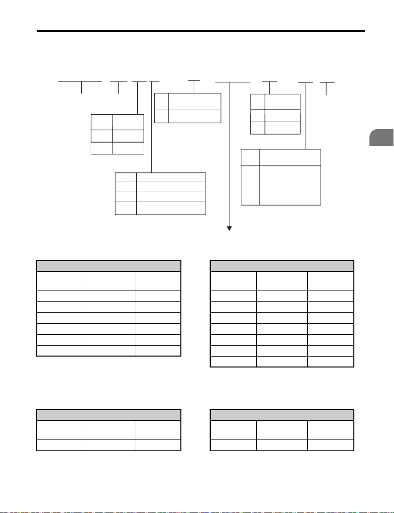
◆ Nameplate
Figure 1.1
Normal Duty Amps/Heavy Duty Amps
AC drive model
Input specifications
Output specifications
Lot number
Serial number
%+/48##$##
/#:#22.+/1614M9M94'8#
#%2*8*\
#
#%2*8*\##
Software version
Enclosure Type
+056#..#6+10%#6')14;
Figure 1.1 Nameplate Information
16 YASKAWA ELECTRIC TOEP C710606 12B YASKAWA AC Drive V1000 Quick Start Guide
PA SS
++
/#&'+0,#2#0
RoHS
Page 17
1.1 Model Number and Nameplate Check
CIMR-
Drive
V
V1000
Series
Region
No.
Code
A Japan
T Asia
2
U
Customized
No.
Specifications
A Standard model
No. Voltage Class
1-phase, 200-240 Vac
B
3-phase, 200-240 Vac
2
3-phase, 380-480 Vac
4
A
0001
B
Enclosure
No.
Type
B IP20
F
NEMA1
Environmental
No.
Specification *
A
Standard
M
Humidity- and
dust-resistant
Oil-resistant
N
Vibration-resistant
S
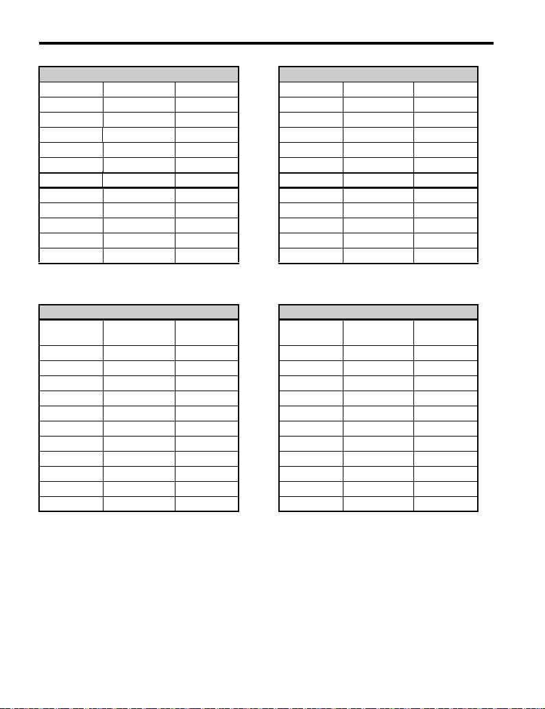
Single-Phase 200 V
Normal Duty Heavy Duty
No.
0001 0.2 1.2 0001 0.1 0.8
0002 0.4 1.9 0002 0.2 1.6
0003 0.75 3.3 0003 0.4 3
0006 1.1 6 0006 0.75 5
0010 2.2 9.6 0010 1.5 8
0012 3.0 12
Max. Motor
Capacity kW
Rated Output
Current A
No.
0012 2.2 11
0018 3.7 17.5
Max. Motor
Capacity kW
A
Design
Revision
Order
Rated Output
Current A
A
Receiving
1
Note: CIMR-VBA0018 is available with a Heavy Duty rating only.
Three-Phase 200 V
Normal Duty Heavy Duty
No.
0001 0.2 1.2 0001 0.1 0.8
YASKAWA ELECTRIC TOEP C710606 12B YASKAWA AC Drive V1000 Quick Start Guide 17
Max. Motor
Capacity kW
Rated Output
Current A
No.
Max. Motor
Capacity kW
Rated Output
Current A
Page 18
1.1 Model Number and Nameplate Check
Normal Duty Heavy Duty
0002 0.4 1.9 0002 0.2 1.6
0004 0.75 3.5 0004 0.4 3
0006 1.1 6 0006 0.75 5
0008 1.5 8.0 0008 1.1 6.9
0010 2.2 9.6 0010 1.5 8
0012 3.0 12 0012 2.2 11
0018 3.7 17.5 0018 3.0 14.0
0020 5.5 19.6 0020 3.7 17.5
0030 7.5 30 0030 5.5 25
0040 11 40 0040 7.5 33
0056 15 56 0056 11 47
0069 18.5 69 0069 15 60
Three-Phase 400 V
Normal Duty Heavy Duty
No.
0001 0.4 1.2 0001 0.2 1.2
0002 0.75 2.1 0002 0.4 1.8
0003 1.5 4.1 0003 0.75 3.4
0004 2.2 5.4 0004 1.5 4.8
0005 3.0 6.9 0005 2.2 5.5
0007 3.7 8.8 0007 3.0 7.2
0011 5.5 11.1 0011 3.7 9.2
0018 7.5 17.5 0018 5.5 14.8
0023 11 23 0023 7.5 18
0031 15 31 0031 11 24
0038 18.5 38 0038 15 31
Max. Motor
Capacity kW
Rated Output
Current A
No.
Max. Motor
Capacity kW
Rated Output
Current A
* Drives with these specifications do not guarantee complete protection for the specified
environmental condition.
18 YASKAWA ELECTRIC TOEP C710606 12B YASKAWA AC Drive V1000 Quick Start Guide
Page 19

2
Mechanical
Installation
This chapter explains how to properly mount and install the
drive.
2.1 MECHANICAL INSTALLATION. . . . . . . . . . . . . . . . . . . . . 20
YASKAWA ELECTRIC TOEP C710606 12B YASKAWA AC Drive V1000 Quick Start Guide
19
Page 20

2.1 Mechanical Installation
2.1 Mechanical Installation
This section outlines specifications, procedures, and environment for proper mechanical
installation of the drive.
◆ Installation Environment
To help prolong the optimum performance life of the drive, install the drive in the proper
environment. The table below provides description of the appropriate environment for the
drive.
Table 2.1 Installation Environment
Environment Conditions
Installation Area Indoors
-10 °C to +40 °C (IP20/NEMA Type 1)
Ambient
Temperature
Humidity 95% RH or less and free of condensation
Storage Temperature -20 °C to +60 °C
Surrounding Area
Altitude 1000 m or lower
Vibration
Orientation Install the drive vertically to maintain maximum cooling effects.
-10 °C to +50 °C (IP20/Open-Chassis)
Drive reliability improves in enviroments without wide temperature fluctuations.
When using an enclosure panel, install a cooling fan or air conditioner in the area to ensure
that the air temperature inside the enclosure does not exceed the specified levels.
Do not allow ice to develop on the drive.
• Install the drive in an area free from:
• oil mist and dust
• metal shavings, oil, water or other foreign materials
• radioactive materials
• combustible materials (e.g., wood)
• harmful gases and liquids
• excessive vibration
•chlorides
• direct sunlight.
10 to 20 Hz at 9.8 m/s
20 to 55 Hz at 5.9 m/s
2
2
NOTICE: Prevent foreign matter such as metal shavings or wire clippings from falling into the drive during
installation and project construction. Failure to comply could result in damage to the drive. Place a
temporary cover over the top of the drive during installation. Remove the temporary cover before start-up, as
the cover will reduce ventilation and cause the drive to overheat.
20 YASKAWA ELECTRIC TOEP C710606 12B YASKAWA AC Drive V1000 Quick Start Guide
Page 21
2.1 Mechanical Installation
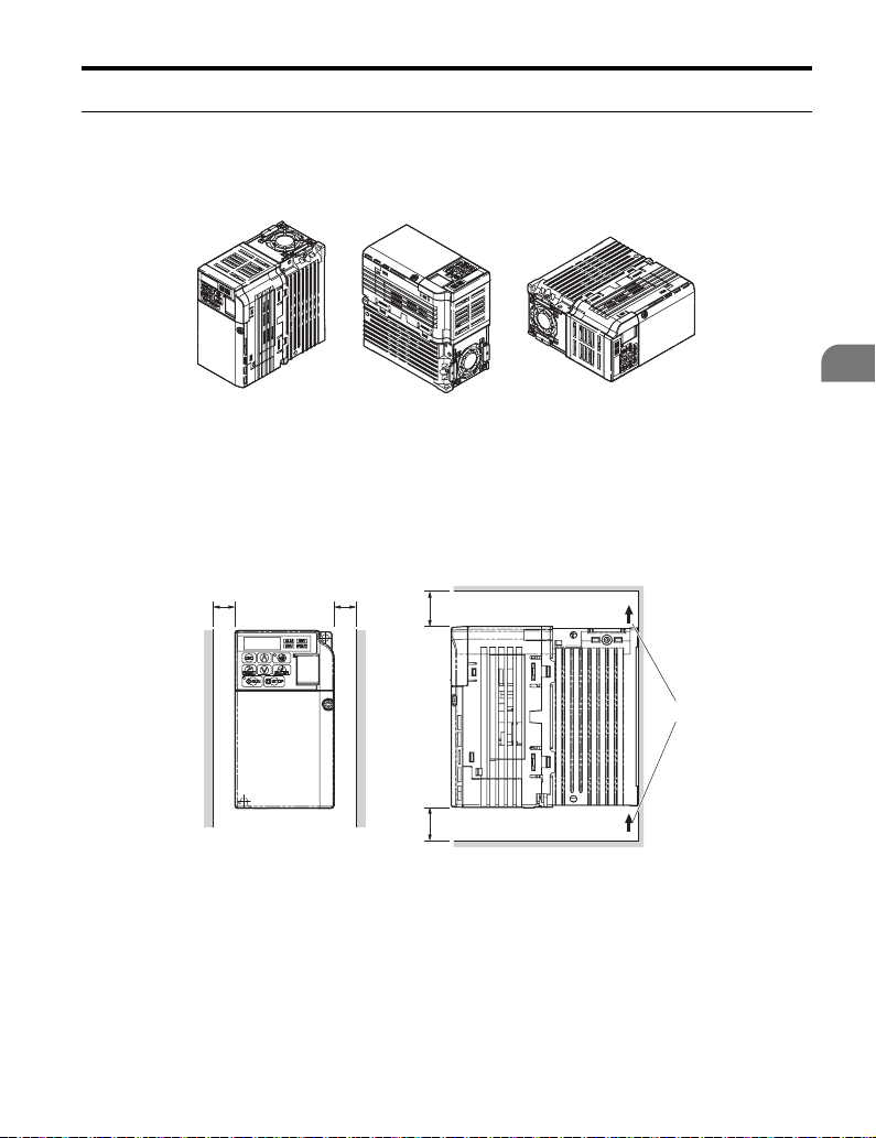
◆ Installation Orientation and Spacing
Install the drive upright as illustrated in Figure 2.1 to maintain proper cooling.
Figure 2.1
■ Single Drive Installation
To maintain sufficient space for airflow and wiring, refer to Figure 2.2. Install the heatsink
against a closed surface to avoid diverting cooling air around the heatsink.
Figure 2.2
ABB
A – Correct B – Incorrect
Figure 2.1 Correct Installation Orientation
Side Clearance
AA
Top/Bottom Clearance
C
Mechanical Installation
2
B
C
A – 30 mm minimum C – 100 mm minimum
B – Airflow direction D –
Figure 2.2 Correct Installation Spacing
Note: IP20/NEMA Type 1 and IP20/Open-Chassis models require the same amount of space above
and below the drive for installation.
YASKAWA ELECTRIC TOEP C710606 12B YASKAWA AC Drive V1000 Quick Start Guide 21
Page 22
2.1 Mechanical Installation
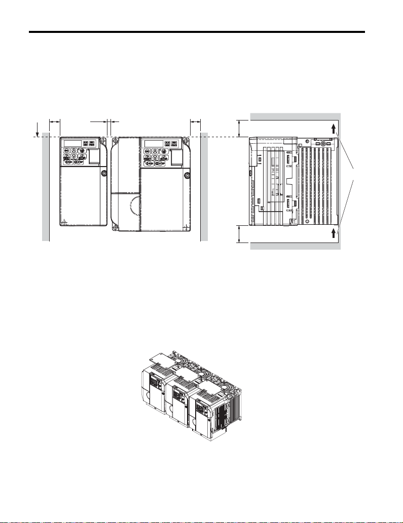
■ Multiple Drive Installation
When installing multiple drives into the same enclosure panel, mount the drives according to
Figure 2.2. When mounting drives with a minimum side-by-side clearance of 2 mm
according to Figure 2.3, derating must be considered and parameter L8-35 must be set.
Refer to Parameter List on page 113.
Figure 2.3
B
A
2 mm
B
C
D
C
A – Line up the tops of the drives. C – 100 mm minimum
B – 30 mm minimum D – Airflow direction
Figure 2.3 Space Between Drives (Side-by-Side Mounting)
Note: When installing drives of different sizes into the same enclosure panel, the tops of the drives
should line up. Leave space between the top and bottom of stacked drives for cooling fan
replacement if required. Using this method, it is possible to replace the cooling fans later.
NOTICE: When drives with IP20/NEMA Type 1 enclosures are mounted side-by-side, the top covers of all
drives must be removed as shown in the figure below.
Figure 2.4
Figure 2.4 IP20/NEMA 1 Side-by-Side Mounting in Enclosure
22 YASKAWA ELECTRIC TOEP C710606 12B YASKAWA AC Drive V1000 Quick Start Guide
Page 23
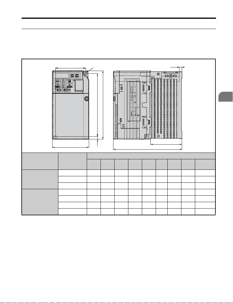
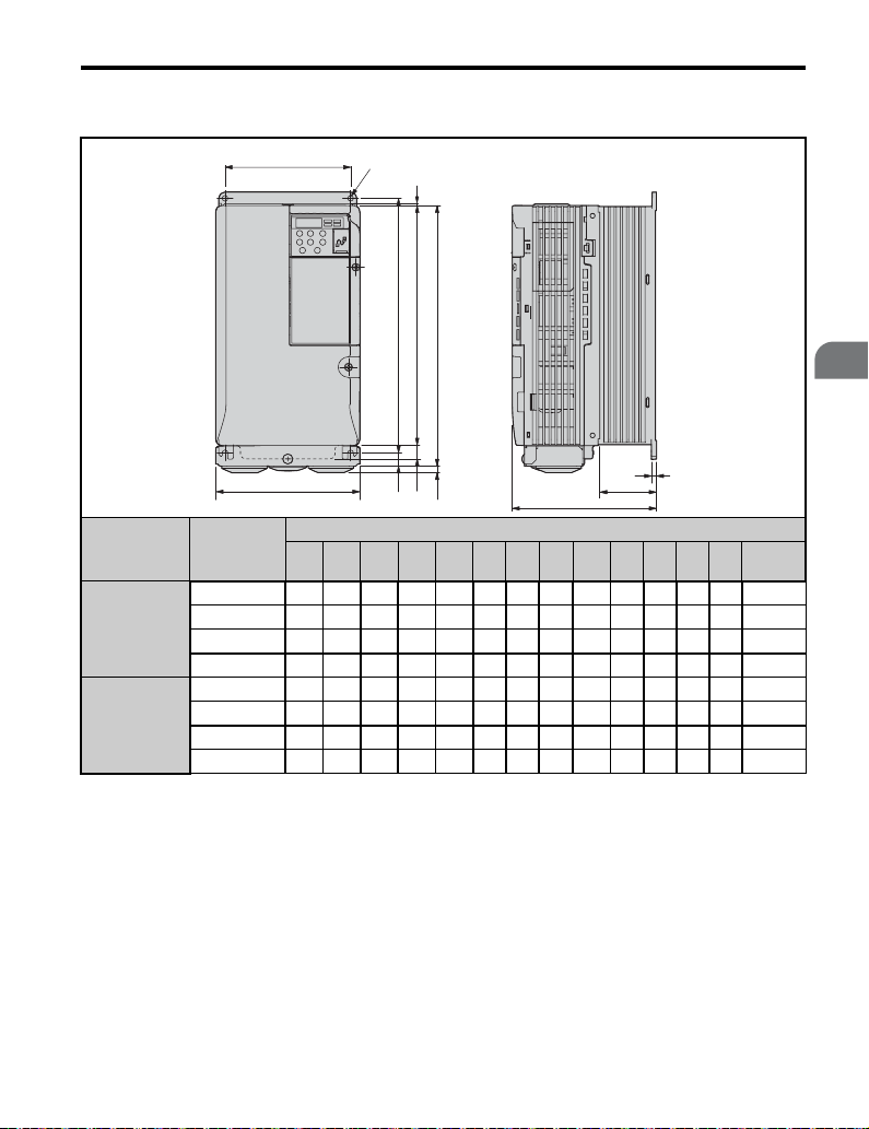
◆ Exterior and Mounting Dimensions
■ IP20/Open-Chassis Drives
Table 2.2 IP20/Open-Chassis (without an EMC filter)
2.1 Mechanical Installation
Voltage Class
Single-Phase
200 V Class
Three-Phase
200 V Class
W1
W
Drive Model
CIMR-V
BA0001B 56 118 68 128 76 3 5 6.5 0.6
BA0002B 56 118 68 128 76 3 5 6.5 0.6
BA0003B 56 118 68 128 118 5 5 38.5 1.0
2A0001B 56 118 68 128 76 3 5 6.5 0.6
2A0002B 56 118 68 128 76 3 5 6.5 0.6
2A0004B 56 118 68 128 108 5 5 38.5 0.9
2A0006B 56 118 68 128 128 5 5 58.5 1.1
2-M4
H
H1H2
D
Dimensions (mm)
W1 H1 W H D t1 H2 D1
t1
D1
Weight
(kg)
Mechanical Installation
2
YASKAWA ELECTRIC TOEP C710606 12B YASKAWA AC Drive V1000 Quick Start Guide 23
Page 24
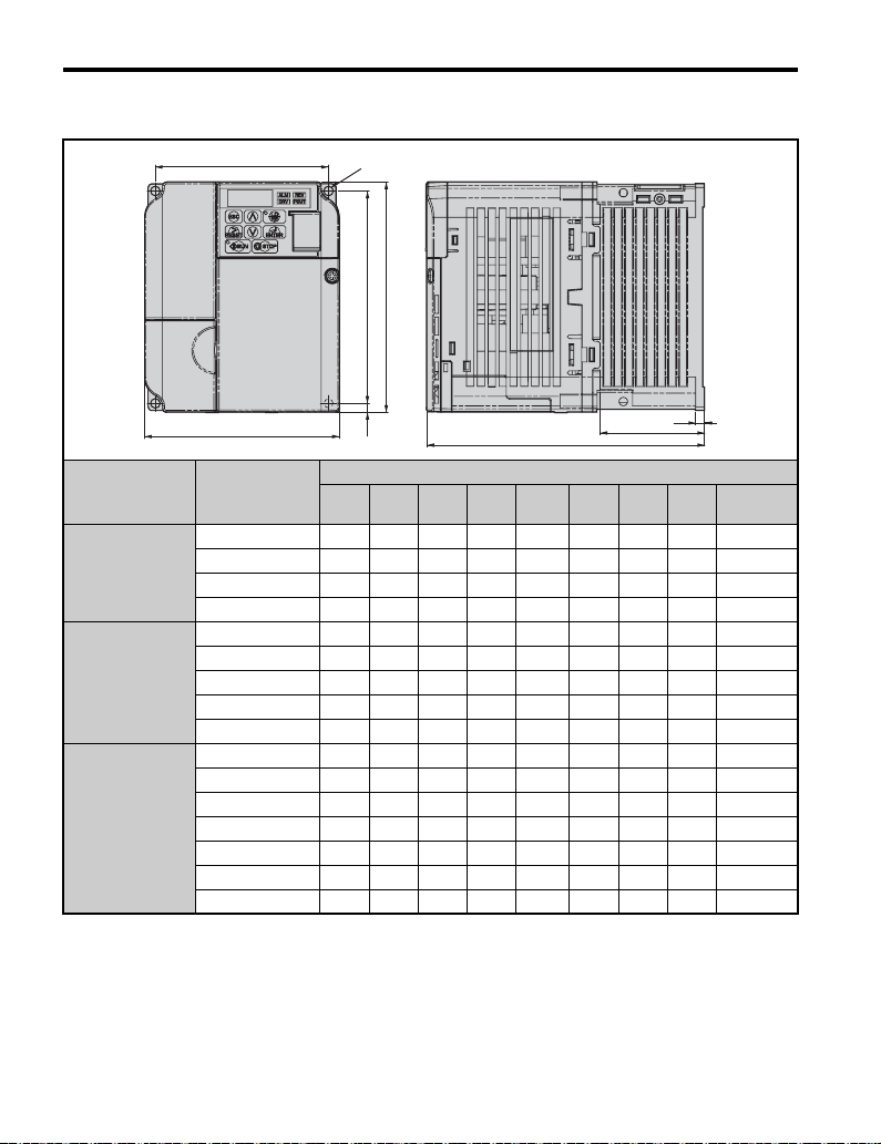
2.1 Mechanical Installation
Table 2.3 IP20/Open-Chassis (without an EMC filter)
Voltage Class
W1
W
Drive Model
CIMR-V
4-M4
H
t1
H2 H1
D
D1
Dimensions (mm)
W1 H1 W H D t1 H2 D1
BA0006B 96 118 108 128 137.5 5 5 58 1.7
Single-Phase
200 V Class
BA0010B 96 118 108 128 154 5 5 58 1.8
BA0012B 128 118 140 128 163 5 5 65 2.4
BA0018B 158 118 170 128 180 5 5 65 3.0
2A0008B 96 118 108 128 129 5 5 58 1.7
Three-Phase 2A0010B 96 118 108 128 129 5 5 58 1.7
200 V Class 2A0012B 96 118 108 128 137.5 5 5 58 1.7
2A0018B 128 118 140 128 143 5 5 65 2.4
2A0020B 128 118 140 128 143 5 5 65 2.4
4A0001B 96 118 108 128 81 5 5 10 1.0
4A0002B 96 118 108 128 99 5 5 28 1.2
Three-Phase
400 V Class
4A0004B 96 118 108 128 137.5 5 5 58 1.7
4A0005B 96 118 108 128 154 5 5 58 1.7
4A0007B 96 118 108 128 154 5 5 58 1.7
4A0009B 96 118 108 128 154 5 5 58 1.7
4A0011B 128 118 140 128 143 5 5 65 2.4
Weight
(kg)
24 YASKAWA ELECTRIC TOEP C710606 12B YASKAWA AC Drive V1000 Quick Start Guide
Page 25
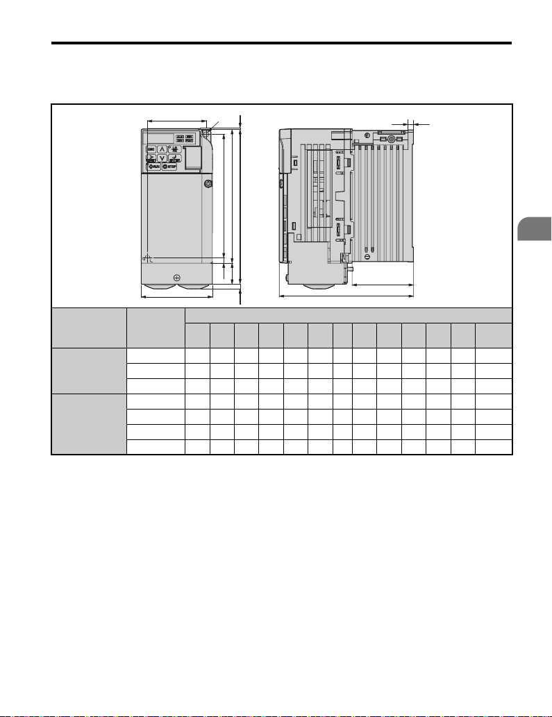
■ IP20/NEMA Type 1 Drives
Table 2.4 IP20/NEMA Type 1 (without an EMC filter)
W1
2-M4
2.1 Mechanical Installation
H6
HH3
H1H4
t1
Mechanical Installation
2
Voltage Class
Single-Phase
200 V Class
H5 H2
W
Drive Model
CIMR-V
W1 H2 W H1 D t1 H5 D1 H H4 H3 H6
Dimensions (mm)
BA0001F 56 118 68 129.5 76 3 5 6.5 149.5 20 4 1.5 0.8
BA0002F 56 118 68 129.5 76 3 5 6.5 149.5 20 4 1.5 0.8
BA0003F 56 118 68 129.5 118 5 5 39 149.5 20 4 1.5 1.2
D1
D
Weight
(kg)
2A0001F 56 118 68 129.5 76 3 5 6.5 149.5 20 4 1.5 0.8
Three-Phase
200 V Class
2A0002F 56 118 68 129.5 76 3 5 6.5 149.5 20 4 1.5 0.8
2A0004F 56 118 68 129.5 108 5 5 39 149.5 20 4 1.5 1.1
2A0006F 56 118 68 129.5 128 5 5 59 149.5 20 4 1.5 1.3
YASKAWA ELECTRIC TOEP C710606 12B YASKAWA AC Drive V1000 Quick Start Guide 25
Page 26
2.1 Mechanical Installation
Table 2.5 IP20/NEMA Type 1 (without an EMC filter)
Voltage Class
W1
W
Drive Model
CIMR-V
4-M4
H6
HH3
H1
H5 H2
H4
D
t1
D1
Dimensions (mm)
W1 H2 W H1 D t1 H5 D1 H H4 H3 H6
Weight
BA0006F 96 118 108 129.5 137.5 5 5 58 149.5 20 4 1.5 1.9
Single-Phase
200 V Class
BA0010F 96 118 108 129.5 154 5 5 58 149.5 20 4 1.5 2.0
BA0012F 128 118 140 133 163 5 5 65 153 20 4.8 5 2.6
BA0018F 158 118 170 133 180 5 5 65 171 38 4.8 5 3.3
2A0008F 96 118 108 129.5 129 5 5 58 149.5 20 4 1.5 1.9
Three-Phase 2A0010F 96 118 108 129.5 129 5 5 58 149.5 20 4 1.5 1.9
200 V Class 2A0012F 96 118 108 129.5 137.5 5 5 58 149.5 20 4 1.5 1.9
2A0018F 128 118 140 133 143 5 5 65 153 20 4.8 5 2.6
2A0020F 128 118 140 133 143 5 5 65 153 20 4.8 5 2.6
4A0001F 96 118 108 129.5 81 5 5 10 149.5 20 4 1.5 1.2
4A0002F 96 118 108 129.5 99 5 5 28 149.5 20 4 1.5 1.4
Three-Phase
400 V Class
4A0004F 96 118 108 129.5 137.5 5 5 58 149.5 20 4 1.5 1.9
4A0005F 96 118 108 129.5 154 5 5 58 149.5 20 4 1.5 1.9
4A0007F 96 118 108 129.5 154 5 5 58 149.5 20 4 1.5 1.9
4A0009F 96 118 108 129.5 154 5 5 58 149.5 20 4 1.5 1.9
4A0011F 128 118 140 133 143 5 5 65 153 20 4.8 5 2.6
(kg)
26 YASKAWA ELECTRIC TOEP C710606 12B YASKAWA AC Drive V1000 Quick Start Guide
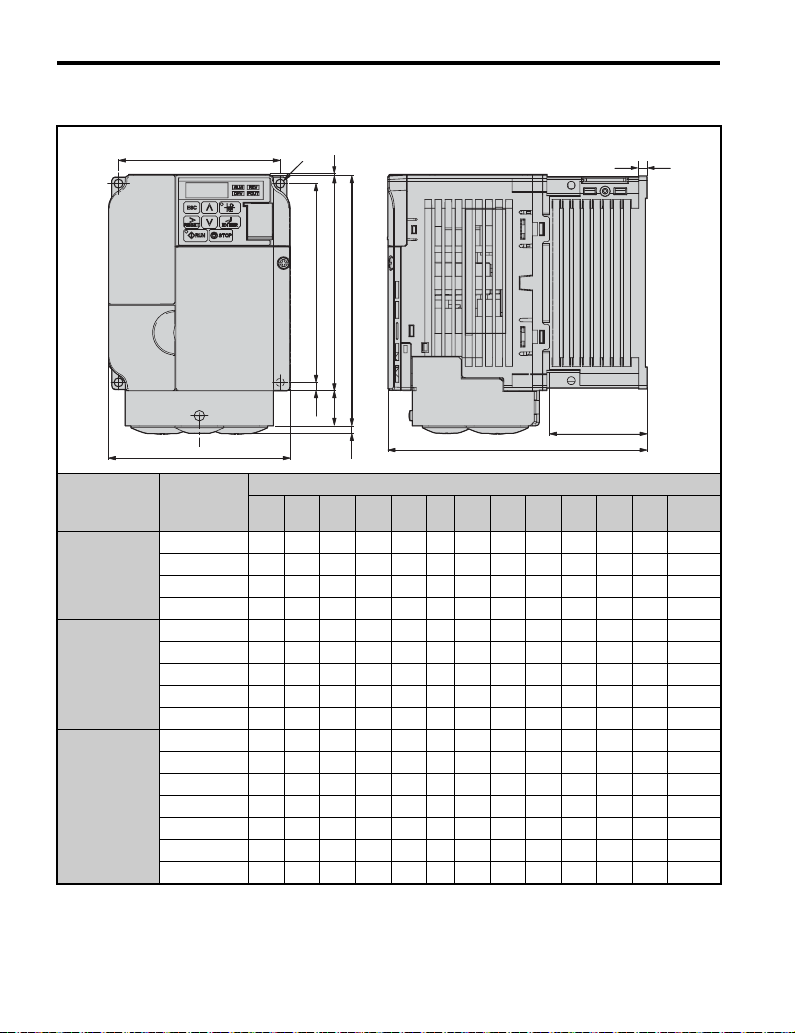
Page 27
2.1 Mechanical Installation
Table 2.6 IP20/NEMA Type 1 (without an EMC filter)
Voltage Class
Three-Phase
200 V Class
Three-Phase
400 V Class
Drive Model
CIMR-V
W1
W
W1 H2 W H1 D t1 H5 D1 H H4 H3 H6 d
4-d
H6
H
H2
H1
t1
H4
H5
H3
D1
D
Dimensions (mm)
2A0030B 122 248 140 234 140 5 13 55 254 13 6 1.5 M5 3.8
2A0040B 122 248 140 234 140 5 13 55 254 13 6 1.5 M5 3.8
2A0056B 160 284 180 270 163 5 13 75 290 15 6 1.5 M5 5.5
2A0069B 192 336 220 320 187 5 22 78 350 15 7 1.5 M6 9.2
4A0018B 122 248 140 234 140 5 13 55 254 13 6 1.5 M5 3.8
4A0023B 122 248 140 234 140 5 13 55 254 13 6 1.5 M5 3.8
4A0031B 160 284 180 270 143 5 13 55 290 15 6 1.5 M5 5.2
4A0038B 160 284 180 270 163 5 13 75 290 13 6 1.5 M5 5.5
Weight
(kg)
Mechanical Installation
2
YASKAWA ELECTRIC TOEP C710606 12B YASKAWA AC Drive V1000 Quick Start Guide 27
Page 28

2.1 Mechanical Installation
28 YASKAWA ELECTRIC TOEP C710606 12B YASKAWA AC Drive V1000 Quick Start Guide
Page 29

3
Electrical
Installation
This chapter explains proper procedures for wiring the control
circuit terminals, motor and power supply.
3.1 STANDARD CONNECTION DIAGRAM. . . . . . . . . . . . . . . 30
3.2 MAIN CIRCUIT WIRING . . . . . . . . . . . . . . . . . . . . . . . . . . . 33
3.3 I/O CONNECTIONS . . . . . . . . . . . . . . . . . . . . . . . . . . . . . .45
3.4 MAIN FREQUENCY REFERENCE . . . . . . . . . . . . . . . . . .47
3.5 WIRING CHECKLIST . . . . . . . . . . . . . . . . . . . . . . . . . . . . .49
YASKAWA ELECTRIC TOEP C710606 12B YASKAWA AC Drive V1000 Quick Start Guide
29
Page 30

3.1 Standard Connection Diagram
3.1 Standard Connection Diagram
Connect the drive and peripheral devices as shown in Figure 3.1. It is possible to run the
drive via the digital operator without connecting digital I/O wiring. This section does not
discuss drive operation; Refer to Start-Up Programming & Operation on page 51 for
instructions on operating the drive.
NOTICE: Inadequate branch short circuit protection could result in damage to the drive. Install adequate
branch circuit short circuit protection per applicable codes. The drive is suitable for circuits capable of
delivering not more than 30,000 RMS symmetrical amperes, 240 Vac maximum (200 V Class) and 480 Vac
maximum (400 V Class).
NOTICE: When the input voltage is 480 V or higher or the wiring distance is greater than 100 meters, pay
special attention to the motor insulation voltage or use an inverter duty motor. Failure to comply could lead
to motor insulation breakdown.
NOTICE: Do not connect the AC control circuit ground to the drive enclosure. Improper drive grounding can
cause the control circuit to malfunction.
NOTICE: The minimum load for the multi-function relay output MA-MB-MC is 10 mA (reference value). If a
circuit requires less than 10 mA, connect it to a photocoupler output (P1, P2, PC). Improper application of
peripheral devices could result in damage to the photocoupler output of the drive.
30 YASKAWA ELECTRIC TOEP C710606 12B YASKAWA AC Drive V1000 Quick Start Guide
Page 31

3.1 Standard Connection Diagram
Figure 3.1
For single phase 200 V
power supply, use
R/L1 and S/L2.
Three phase
power supply
200 to 240 V
THRX
2 MCCB
Thermal relay for
motor cooling fan
Terminals +1, +2, , B1, and B2
are for connecting options.
Never connect power supply
lines to these terminals.
1 MCCB
R/L1
S/L2
T/L3
MC
OFF
ON
SA
MC
THRX
SA
MC MA
Fault relay
Digital inputs
(default setting)
Main speed
frequency
reference.
Multi-function
programmable
Safe Disable
Input
TRX
TRX
SA
MC
_
2 MCCB
MC
Forward run/stop
Reverse run/stop
External fault
Fault reset
Multi-step
speed 1
main/aux switch
Multi-step
speed 2
Jog reference
2 k
Safety switch
Jumper
DC reactor
(option)
*3
r1
s1
t1
R/L1
S/L2
T/L3
4
*
S1
S2
S3
S4
S5
S6
S7
*
DIP
switch S3
SC
Shield ground
terminal
Pulse train input
RP
(max. 32 kHz)
Setting power supply
+V
+10.5 max. 20 mA
A1
0 to +10 V (20 k )
A2
0 to +10 V (20 k )
(0)4 to 20 mA (250 )
AC
HC
8
*
H1
main circuit terminal
Jumper
Main circuit
Control circuit
5
DIP
switch
S2
shielded line
1
*
Thermal relay
(option)
-
B1+1+2 B2
V1000
+
24
V 8 mA
V
24
Sink
Source
V
0
Cable shield ground
twisted-pair shielded line
control terminal
2
*
Braking resistor
(option)
U/T1
V/T2
W/T3
Option card
connector
DIP switch S1
VI
MP
AM
AC
Termination
resistor
120
, 1/2 W
MA
MB
MC
P1
P2
PC
R
R
S
S
IG
Figure 3.1 Drive Standard Connection Diagram
Motor
Cooling fan
FU
r1
FV
s1
FW
t1
U
V
W
Ground
or less (400 V class)
10
100 or less (200 V class)
6
*
Digital output
250 Vac, 10 mA to 1 A
30 Vdc, 10 mA to 1 A
(default setting)
Fault
Digital output
5 ~ 48 Vdc
2 to 50 mA
(default setting)
During Run
(photocoupler 1)
Frequency agree
(photocoupler 2)
Photocoupler
output common
Pulse train output
0 to 32 kHz
Analog monitor
output
+
AM
0 to +10 Vdc
(2 mA)
-
+
-
+
-
Comm.
connector
Monitor
output
MEMOBUS/
Modbus comm.
RS-485/422
M
M
Electrical Installation
3
7
*
YASKAWA ELECTRIC TOEP C710606 12B YASKAWA AC Drive V1000 Quick Start Guide 31
Page 32

3.1 Standard Connection Diagram
* 1. Remove the jumper when installing an optional DC reactor.
* 2. The MC on the input side of the main circuit should open when the thermal relay is triggered.
* 3. Self-cooled motors do not require separate cooling fan motor wiring.
* 4. Connected using sequence input signal (S1 to S7) from NPN transistor; Default: sink mode ( 0 V com)
* 5. Use only a +24 V internal power supply in sinking mode; the source mode requires an external power
supply. Refer to I/O Connections on page 45.
* 6. Minimum load: 5 Vdc, 10 mA (reference value).
* 7. Monitor outputs work with devices such as analog frequency meters, ammeters, voltmeters and
wattmeters; they are intended for use as a feedback-type of signal.
* 8. Disconnect the wire jumper between HC and H1 when utilizing the safety input.
WARNING! Sudden Movement Hazard. Do not close the wiring for the control circuit unless the
multifunction input terminal parameter is properly set (S5 for 3-wire; H1-05 = “0”). Improper sequencing of
run/stop circuitry could result in death or serious injury from moving equipment.
WARNING! Sudden Movement Hazard. Ensure start/stop and safety circuits are wired properly and in the
correct state before energizing the drive. Failure to comply could result in death or serious injury from
moving equipment. When programmed for 3-wire control, a momentary closure on terminal S1 may cause
the drive to start.
WARNING! When 3-Wire sequence is used, set the drive to 3-Wire sequence before wiring the control
terminals and ensure parameter b1-17 is set to 0 (drive does not accept a run command at power up
(default)). If the drive is wired for 3-Wire sequence but set up for 2-Wire sequence (default) and if parameter
b1-17 is set to 1 (drive accepts a Run command at power up), the motor will rotate in reverse direction at
power up of the drive and may cause injury.
WARNING! When the application preset funcion is executed (or A1-06 is set to any value other than 0) the
drive I/O terminal funcitons change. This may cause unexpected operation and potential damage to
equipment or injury.
Figure 3.2 illustrates an example of a 3-wire sequence.
Figure 3.2
Stop relay (N.C.)
Run relay (N.O.)
S1
Run command (run on momentary close)
S2
Stop command (stop on momentary open)
S5
Foward/reverse command
(multi-function input: H1-05 = 0)
SC
Sequence input common
Drive
Figure 3.2 3-Wire Sequence
32 YASKAWA ELECTRIC TOEP C710606 12B YASKAWA AC Drive V1000 Quick Start Guide
Page 33

3.2 Main Circuit Wiring
3.2 Main Circuit Wiring
This section describes the functions, specifications, and procedures required to safely and
properly wire the main circuit of the drive.
NOTICE: Do not solder the ends of wire connections to the drive. Soldered wiring connections can loosen
over time. Improper wiring practices could result in drive malfunction due to loose terminal connections.
◆ Main Circuit Terminal Functions
Table 3.1 Main Circuit Terminal Functions
Ter mi nal Typ e Function Reference
R/L1
S/L2
T/L3
U/T1
W/T3
B1
B2
+1
+2
+1
–
(2 terminals)
Main circuit power
supply input
Drive output Connects to the motor. 37V/T2
Braking resistor
DC reactor
connection
DC power supply
input
Ground
Connects line power to the drive.
Drives with single phase 200 V input power use terminals R/L1
and S/L2 only (T/L3 must not be used).
Available for connecting a braking resistor or the braking resistor
unit option.
These terminals are shorted at shipment. Remove the shorting bar
between +1 and +2 when connecting to this terminal.
For connecting a DC power supply. -
Grounding Terminal
For 200 V class: 100 Ω or less
For 400 V class: 10 Ω or less
37
Electrical Installation
3
◆ Wire Gauges and Tightening Torque
Select the appropriate wires and crimp terminals from Ta bl e 3. 2 through Table 3.5.
Note: 1. Wire gauge recommendations based on drive continuous current ratings using 75°C 600 Vac vinyl-
• Consider the amount of voltage drop when selecting wire gauges.
Increase the wire gauge when the voltage drop is greater than 2% of motor rated voltage.
Ensure the wire gauge is suitable for the terminal block. Use the following formula to
calculate the amount of voltage drop:
• Line drop voltage (V) = 3 x wire resistance (Ω/km) x wire length (m) x current (A) x10
YASKAWA ELECTRIC TOEP C710606 12B YASKAWA AC Drive V1000 Quick Start Guide 33
sheathed wire assuming ambient temperature within 30°C and wiring distance less than 100 m.
2. Terminals +1, +2, –, B1 and B2 are for connecting optional devices such as a DC reactor or braking
resistor. Do not connect other non-specified devices to these terminals.
-3
Page 34

3.2 Main Circuit Wiring
• Refer to instruction manual TOBPC72060000 for braking unit or braking resistor unit
wire gauges.
• Refer to Standards Compliance on page 143 for information on UL compliance.
■ Single-Phase 200 V Class
Table 3.2 Wire Gauge and Torque Specifications
Model
CIMRVBA
0001
0002
0003
0006
0010
0012
0018
■
Three-Phase 200 V Class
Ter min al
R/L1, S/L2, U/T1, V/T2, W/
T3, –, +1, +2, B1, B2,
R/L1, S/L2, U/T1, V/T2, W/
T3, –, +1, +2, B1, B2,
R/L1, S/L2, U/T1, V/T2, W/
T3,
–, +1, +2, B1, B2, M4
R/L1, S/L2, U/T1, V/T2, W/
T3, –, +1, +2, B1, B2,
R/L1, S/L2, U/T1, V/T2, W/
T3, –, +1, +2, B1, B2,
Table 3.3 Wire Gauge and Torque Specifications
Model
CIMRV2A
0001
0002
0004
0006
0010
0012
0020
Ter min al
R/L1, S/L2, T/L3, U/T1, V/T2,
W/T3, –, +1, +2, B1, B2,
R/L1, S/L2, T/L3, U/T1, V/T2,
W/T3, –, +1, +2, B1, B2
R/L1, S/L2, T/L3, U/T1, V/T2,
W/T3, –, +1, +2, B1, B2,
R/L1, S/L2, T/L3, U/T1, V/T2,
W/T3, –, +1, +2, B1, B2,
Screw
Size
M3.5
M4
M4
M4
M5
Screw
Size
M3.5
M4
M4
M4
M4
Tightening
Torque
N•m (lb.in.)
0.8 to 1.0
(7.1 to 8.9)
1.2 to 1.5
(10.6 to 13.3)
1.2 to 1.5
(10.6 to 13.3)
1.2 to 1.5
(10.6 to 13.3)
1.2 to 1.5
(10.6 to 13.3)
2 to 2.5
(17.7 to 22.1)
Tightening
Torque
N•m (lb.in.)
0.8 to 1.0
(7.1 to 8.9)
1.2 to 1.5
(10.6 to 13.3)
1.2 to 1.5
(10.6 to 13.3)
1.2 to 1.5
(10.6 to 13.3)
1.2 to 1.5
(10.6 to 13.3)
Applicable
Gauge
2
(AWG)
mm
0.75 to 2.0
(18 to 14)
2.0 to 5.5
(14 to 10)
2.0 to 5.5
(14 to 10)
2.0 to 5.5
(14 to 10)
2.0 to 5.5
(14 to 10)
3.5 to 8
(12 to 8)
Applicable
Gauge
2
(AWG)
mm
0.75 to 2.0
(18 to 14)
2.0 to 5.5
(14 to 10)
2.0 to 5.5
(14 to 10)
2.0 to 5.5
(14 to 10)
2.0 to 5.5
(14 to 10)
Recommended
Gauge
2
(AWG)
mm
2
(14)
2
(14)
3.5
(12)
5.5
(10)
5.5
(10)
8(8) Note: 1.
Recommended
Gauge
2
(AWG)
mm
2
(14)
2
(14)
3.5
(12)
3.5
(12)
5.5
(10)
Note: 1.
Note: 1.
Note: 1.
Note: 1.
Note: 1.
Note: 1.
Note: 1.
Note: 1.
Note: 1.
Note: 1.
Line
Typ e
Line
Typ e
34 YASKAWA ELECTRIC TOEP C710606 12B YASKAWA AC Drive V1000 Quick Start Guide
Page 35

3.2 Main Circuit Wiring
Model
CIMRV2A
0030
0040
0056
0069
Ter min al
R/L1,S/L2,T/L3,U/T1,V/
T2,W/T3,-,+1,+2
B1,B2 M4
R/L1,S/L2,T/L3,U/T1,V/
T2,W/T3,-,+1,+2
B1,B2 M4
R/L1,S/L2,T/L3,U/T1,V/
T2,W/T3,-,+1,+2
B1,B2 M5
R/L1,S/L2,T/L3,U/T1,V/
T2,W/T3,-,+1,+2
B1,B2 M5
■ Three-Phase 400 V Class
Table 3.4 Wire Gauge and Torque Specifications
Model
CIMRV4A
0001
0002
0004
0005
0007
0009
Ter mi nal
R/L1, S/L2, T/L3, U/T1, V/T2,
W/T3, –, +1, +2, B1, B2,
R/L1, S/L2, T/L3, U/T1, V/T2,
W/T3, –, +1, +2, B1, B2
Screw
Size
M5
M5
M5
M5
M6
M6
M8
M6
Screw
Size
M4
M4
M4
Tightening
Torque
N•m (lb.in.)
2 to 2.5
(17.7 to 22.1)
1.2 to 1.5
(10.6 to 13.3)
2 to 2.5
(17.7 to 22.1)
2 to 2.5
(17.7 to 22.1)
1.2 to 1.5
(10.6 to 13.3)
2 to 2.5
(17.7 to 22.1)
4 to 6
(35.4 to 53.1)
2 to 2.5
(17.7 to 22.1)
4 to 6
(35.4 to 53.1)
9 to 11
(79.7 to 11.0)
2 to 2.5
(17.7 to 22.1)
4 to 6
(35.4 to 53.1)
Tightening
Tor que
N•m (lb.in.)
1.2 to 1.5
(10.6 to 13.3)
1.2 to 1.5
(10.6 to 13.3)
1.2 to 1.5
(10.6 to 13.3)
Applicable
Gauge
2
(AWG)
mm
5.5 to 14
(10 to 6)
2.0 to 5.5
(14 to 10)
5.5 to 14
(10 to 6)
5.5 to 14
(10 to 6)
2.0 to 5.5
(14 to 10)
5.5 to 14
(10 to 6)
14 to 22
(6 to 4)
5.5 to 8
(10 to 8)
14 to 22
(6 to 4)
8 to 38
(8 to 2)
8 to 14
(8 to 6)
8 to 22
(8 to 4)
Applicable
Gauge
2
(AWG)
mm
2.0 to 5.5
(14 to 10)
2.0 to 5.5
(14 to 10)
2.0 to 5.5
(14 to 10)
Recommended
Gauge
2
(AWG)
mm
8
(8)
5.5
(10)
8
(8)
14
(6)
5.5
(10)
8
(8)
22
(4)
8
(8)
22
(4)
38
(2)
14
(6)
22
(4)
Recommended
Gauge
2
(AWG)
mm
2
(14)
2
(14)
3.5
(12)
Line
Typ e
Note: 1.
Note: 1.
Note: 1.
Note: 1.
Note: 1.
Note: 1.
Note: 1.
Note: 1.
Note: 1.
Note: 1.
Note: 1.
Note: 1.
Line
Typ e
Note: 1.
Note: 1.
Note: 1.
Electrical Installation
3
YASKAWA ELECTRIC TOEP C710606 12B YASKAWA AC Drive V1000 Quick Start Guide 35
Page 36

3.2 Main Circuit Wiring
Model
CIMRV4A
0011
0018
0023
0031
0038
Ter min al
R/L1, S/L2, T/L3, U/T1, V/T2,
W/T3, –, +1, +2, B1, B2
R/L1,S/L2,T/L3,U/T1,V/
T2,W/T3,-,+1,+2
B1,B2 M4
R/L1,S/L2,T/L3,U/T1,V/
T2,W/T3,-,+1,+2
B1,B2 M4
R/L1,S/L2,T/L3,U/T1,V/
T2,W/T3,-,+1,+2
B1,B2 M5
R/L1,S/L2,T/L3,U/T1,V/
T2,W/T3,-,+1,+2
B1,B2 M5
Screw
Size
M4
M4
M4
M5
M5
M5
M5
M6
M5
M6
Tightening
Tor que
N•m (lb.in.)
1.2 to 1.5
(10.6 to 13.3)
1.2 to 1.5
(10.6 to 13.3)
1.2 to 1.5
(10.6 to 13.3)
1.2 to 1.5
(10.6 to 13.3)
2 to 2.5
(17.7 to 22.1)
2 to 2.5
(17.7 to 22.1)
1.2 to 1.5
(10.6 to 13.3)
2 to 2.5
(17.7 to 22.1)
2 to 2.5
(17.7 to 22.1)
2 to 2.5
(17.7 to 22.1)
4 to 6
(35.4 to 53.1)
2 to 2.5
(17.7 to 22.1)
2 to 2.5
(17.7 to 22.1)
4 to 6
(35.4 to 53.1)
Applicable
Gauge
2
(AWG)
mm
2.0 to 5.5
(14 to 10)
2.0 to 5.5
(14 to 10)
2.0 to 5.5
(14 to 10)
2.0 to 5.5
(14 to 10)
5.5 to 14
(10 to 6)
5.5 to 14
(10 to 6)
2.0 to 5.5
(14 to 10)
5.5 to 14
(10 to 6)
5.5 to 14
(10 to 6)
5.5 to 8
(10 to 8)
5.5 to 14
(10 to 6)
5.5 to 14
(10 to 6)
5.5 to 8
(10 to 8)
5.5 to 14
(10 to 6)
Recommended
Gauge
2
(AWG)
mm
2
(14)
3.5
(12)
5.5
(10)
5.5
(10)
5.5
(10)
8
(8)
5.5
(10)
5.5
(10)
8
(8)
8
(8)
8
(8)
14
(6)
8
(8)
8
(8)
Line
Typ e
Note: 1.
Note: 1.
Note: 1.
Note: 1.
Note: 1.
Note: 1.
Note: 1.
Note: 1.
Note: 1.
Note: 1.
Note: 1.
Note: 1.
Note: 1.
Note: 1.
◆ Main Circuit Terminal Power Supply and Motor Wiring
This section outlines the various steps, precautions, and checkpoints for wiring the main
circuit terminals and motor terminals.
NOTICE: When connecting the motor to the drive output terminals U/T1, V/T2, and W/T3, the phase order
for the drive and motor should match. Failure to comply with proper wiring practices may cause the motor to
run in reverse if the phase order is backward.
NOTICE: Do not connect phase-advancing capacitors or LC/RC noise filters to the output circuits. Improper
application of noise filters could result in damage to the drive.
NOTICE: Do not connect the AC power line to the output motor terminals of the drive. Failure to comply
could result in death or serious injury by fire as a result of drive damage from line voltage application to
36 YASKAWA ELECTRIC TOEP C710606 12B YASKAWA AC Drive V1000 Quick Start Guide
Page 37

3.2 Main Circuit Wiring
output terminals.
■ Cable Length Between Drive and Motor
When the cable length between the drive and the motor is too long (especially at low
frequency output), note that the cable voltage drop may cause reduced motor torque. Drive
output current will increase as the leakage current from the cable increases. An increase in
leakage current may trigger an overcurrent situation and weaken the accuracy of the current
detection.
Adjust the drive carrier frequency according to the following table. If the motor wiring
distance exceeds 100 m because of the system configuration, reduce the ground currents.
Refer to Carrier Frequency Selection: C6-02 on page 71.
Refer to Table 3.5 to set the carrier frequency to an appropriate level.
Table 3.5 Cable Length Between Drive and Motor
Cable Length 50 m or less 100 m or less Greater than 100 m
Carrier Frequency 15 kHz or less 5 kHz or less 2 kHz or less
Note: When setting carrier frequency, calculate the cable length as the total distance of wiring to all
connected motors when running multiple motors from a single drive.
■ Ground Wiring
Follow the precautions to wire the ground for one drive or a series of drives.
WARNING! Electrical Shock Hazard. Always use a ground wire that complies with technical standards on
electrical equipment and minimize the length of the ground wire. Improper equipment grounding may cause
dangerous electrical potentials on equipment chassis, which could result in death or serious injury.
WARNING! Electrical Shock Hazard. Be sure to ground the drive ground terminal. (200 V Class: Ground to
100 Ω or less, 400 V Class: Ground to 10 Ω or less). Improper equipment grounding could result in death or
serious injury by contacting ungrounded electrical equipment.
NOTICE: Do not share the ground wire with other devices such as welding machines or large-current
electrical equipment. Improper equipment grounding could result in drive or equipment malfunction due to
electrical interference.
NOTICE: When using more than one drive, ground multiple drives according to instructions. Improper
equipment grounding could result in abnormal operation of drive or equipment.
Refer to Figure 3.3 when using multiple drives. Do not loop the ground wire.
Electrical Installation
3
YASKAWA ELECTRIC TOEP C710606 12B YASKAWA AC Drive V1000 Quick Start Guide 37
Page 38

3.2 Main Circuit Wiring
A
Figure 3.3
A
A – Correct B – Incorrect
Figure 3.3 Multiple Drive Wiring
A
B
■ Wiring the Main Circuit Terminal
WARNING! Electrical Shock Hazard. Shut off the power supply to the drive before wiring the main circuit
terminals. Failure to comply may result in death or serious injury.
Note: 1. A cover placed over the DC Bus and braking circuit terminals prior to shipment helps prevent
miswiring. Cut away covers as needed for terminals with a needle-nose pliers.
A – Protective Cover to Prevent Miswiring
2. The ground terminal screw on IP20/NEMA Type 1 holds the protective cover in place.
◆ Control Circuit Terminal Block Functions
Drive parameters determine which functions apply to the multi-function digital inputs (S1 to
S7), multi-function digital outputs (MA, MB), multi-function pulse inputs and outputs (RP,
MP) and multi-function photocoupler outputs (P1, P2). The default is called out next to each
terminal.
WARNING! Sudden Movement Hazard. Always check the operation and wiring of control circuits after being
wired. Operating a drive with untested control circuits could result in death or serious injury.
WARNING! Confirm the drive I/O signals and external sequence before starting test run. Setting parameter
A1-06 may change the I/O terminal function automatically from the factory setting. Refer to Application
Presets on page 64. Failure to comply may result in death or serious injury.
NOTICE: Do not switch an input contactor more often than once every 30 minutes. Improper equipment
sequencing could shorten useful life of the drive electrolytic capacitors and circuit relays. Normally the drive
I/O should be used to stop and start the motor.
38 YASKAWA ELECTRIC TOEP C710606 12B YASKAWA AC Drive V1000 Quick Start Guide
Page 39

3.2 Main Circuit Wiring
■ Input Terminals
Table 3.6 Control Circuit Input Terminals
Typ e No. Terminal Name (Function) Function (Signal Level) Default Setting
Multi-function input 1 (Closed: Forward
S1
run, Open: Stop)
Multi-function input 2 (Closed: Reverse
S2
run, Open: Stop)
Photocoupler
24 Vdc, 8 mA Note: Drive preset to sinking mode.
When using source mode, set DIP switch S3 to allow
for a 24 Vdc (±10%) external power supply. Refer to
page 45.
Sequence common
Open: Coast to stop safety input
Closed: Normal operation Note: Disconnect wire
jumper between HC and H1 when using safety input.
Response frequency: 0.5 to 32 kHz
(Duty Cycle: 30 to 70%)
(High level voltage: 3.5 to 13.2 Vdc)
(Low level voltage: 0.0 to 0.8 Vdc)
(input impedance: 3 kΩ)
Input voltage 0 to +10 Vdc (20 kΩ) resolution
1/1000
Input voltage or input current (Selected by DIP
switch S1) 0 to +10 Vdc (20 kΩ) resolution: 1/1000
4 to 20 mA (250 Ω) or 0 to 20 mA (250 Ω)
resolution: 1/500
MultiFunction
Digital
Inputs
Safety
Input
Main
Frequency
Reference
Input
Multi-function input 3 (External fault
S3
(N.O.))
S4 Multi-function input 4 (Fault reset)
Multi-function input 5 (Multi-step speed
S5
reference 1)
Multi-function input 6 (Multi-step speed
S6
reference 2)
S7 Multi-function input 7 (Jog reference)
Multi-function input common (Control
SC
common)
HC Power supply for safety input command +24 Vdc (max 10 mA allowed)
H1 Safety input command
Multi-function pulse train input (frequency
RP
reference)
+V Analog input power supply +10.5 Vdc (max allowable current 20 mA)
Multi-function analog input (frequency
A1
reference)
Multi-function analog input (frequency
A2
reference)
AC Frequency reference common 0 Vdc
Electrical Installation
3
YASKAWA ELECTRIC TOEP C710606 12B YASKAWA AC Drive V1000 Quick Start Guide 39
Page 40

3.2 Main Circuit Wiring
■ Output Terminals
Table 3.7 Control Circuit Output Terminals
Typ e No. Terminal Name (Function)
MA N.O. (fault) Digital output
Multi-Function
Digital Output
Multi-Function
Photocoupler
Output
Monitor Output
MB N.C. output (fault)
MC Digital output common
P1 Photocoupler output 1 (during run)
PC Photocoupler output common
MP Pulse train output (input frequency) 32 kHz (max)
AM Analog monitor output 0 to 10 Vdc (2 mA or less) Resolution: 1/1000
AC Monitor common 0 V
Function (Signal Level)
Default Setting
30 Vdc, 10 mA to 1 A; 250 Vac, 10 mA to 1
A.
Minimum Load: 5 Vdc, 10 mA (reference
value)
Photocoupler output 48 Vdc, 2 to 50 mAP2 Photocoupler output 2 (Frequency agree)
Connect a suppression diode as shown in Figure 3.4 when driving a reactive load such as a
relay coil. Ensure the diode rating is greater than the circuit voltage.
40 YASKAWA ELECTRIC TOEP C710606 12B YASKAWA AC Drive V1000 Quick Start Guide
Page 41

3.2 Main Circuit Wiring
A
Figure 3.4
B
C
D
A – External power, 48 V max. C – Coil
B – Suppression diode D – 50 mA or less
Figure 3.4 Connecting a Suppression Diode
■ Serial Communication Terminals
Table 3.8 Control Circuit Terminals: Serial Communications
Typ e No. Signal Name Function (Signal Level)
R+ Communications input (+)
MEMOBUS/
Modbus
Communication
R- Communications input (-)
S+ Communications output (+)
S- Communications output (-)
IG Shield ground 0 V
◆ Removable Terminal Block Configuration
Figure 3.5
R+ R
㧙
S+ S㧙IG
P1 P2 PC A1 A2 +V AC AM AC MP
S1 S2 S3 S4 S5 S6 S7 HC SC H1 RP
MCMBMA
MEMOBUS/Modbus
communication: Use a RS-485
or RS-422 cable to connect the
drive.
㧙
S+ S㧙IG
R+ R
P1 P2 PC A1 A2 +V AC AM AC MP
S1 S2 S3 S4 S5 S6 S7 HC SC H1 RP
RS-485/422 MEMOBUS/
Modbus communication
protocol 115.2 kbps (max.)
MCMBMA
Electrical Installation
3
Figure 3.5 Removable Control Circuit Terminal Block
(CIMR-VA; CIMR-VU)
■ Wire Size and Torque Specifications
Select the appropriate wires and crimp terminals from Ta bl e 3. 3. Crimp a ferrule to signal
wiring to improve wiring simplicity and reliability. Refer to Ferrule Terminal Types and
Sizes on page 42.
YASKAWA ELECTRIC TOEP C710606 12B YASKAWA AC Drive V1000 Quick Start Guide 41
Page 42

3.2 Main Circuit Wiring
Table 3.9 Wire Size and Torque Specifications (Same for All Models)
Tightening
Ter mi nal
Screw
Size
Tor que
Nxm
MA, MB, MC M3 0.5 to 0.6
S1-S7, SC, RP, +V, A1,
A2, AC, HC, H1, P1,
P2, PC, MP, AM, AC,
S+, S-, R+, R-, IG
■
Ferrule-Type Wire Terminations
M2 0.22 to 0.25
Crimp a ferrule to signal wiring to improve wiring simplicity and reliability. Use
CRIMPFOX ZA-3, a crimping tool manufactured by PHOENIX CONTACT.
Figure 3.6
Bare Wire Terminal Ferrule-Type Terminal
Applicable
wire size
2
mm
(AWG)
Stranded wire:
0.25 to 1.5
(24 to 16)
Single wire:
0.25 to 1.5 (24
Recomm.
mm
(AWG)
0.75 (18)
2
Applicable
wire size
2
mm
(AWG)
0.25 to 1.0
(24 to 18)
Recomm.
mm
(AWG)
0.5 (20)
to 16)
Stranded wire:
0.25 to 1.0
(24 to 18)
Single wire:
0.25 to 1.5
0.75 (18)
0.25 to 0.5
(24 to 20)
0.5 (20)
(24 to 16)
φd1
6 mm
L
2
Wire Type
Shielded
line, etc.
φd2
Figure 3.6 Ferrule Dimensions
Table 3.10 Ferrule Terminal Types and Sizes
Size mm2 (AWG) Ty pe L (mm) d1 (mm) d2 (mm) Manufacturer
0.25 (24) AI 0.25-6YE 10.5 0.8 2
0.34 (22) AI 0.34-6TQ 10.5 0.8 2
0.5 (20) AI 0.5-6WH 12 1.1 2.5
0.75 (18) A1 0.75-6GY 12 1.3 2.8
1.0 AI 1-6RD 12 1.5 3.0
42 YASKAWA ELECTRIC TOEP C710606 12B YASKAWA AC Drive V1000 Quick Start Guide
PHOENIX CONTACT
Page 43

3.2 Main Circuit Wiring
◆ Wiring Procedure
This section describes the proper procedures and preparations for wiring the terminal board.
WARNING! Electrical Shock Hazard. Do not remove covers or touch the circuit boards while the power is
on. Failure to comply could result in death or serious injury.
NOTICE: Separate control circuit wiring from main circuit wiring (terminals R/L1, S/L2, T/L3, B1, B2, U/T1,
V/T2, W/T3, -, +1, +2) and other high-power lines. Improper wiring practices could result in drive malfunction
due to electrical interference.
NOTICE: Separate wiring for digital output terminals MA, MB and MC from wiring to other control circuit
lines. Improper wiring practices could result in drive or equipment malfunction or nuisance trips.
NOTICE: Use a class 2 power supply (UL standard) when connecting to the control terminals. Improper
application of peripheral devices could result in drive performance degradation due to improper power
supply.
NOTICE: Insulate shields with tape or shrink tubing to prevent contact with other signal lines and
equipment. Improper wiring practices could result in drive or equipment malfunction due to short circuit.
NOTICE: Connect the shield of shielded cable to the appropriate ground terminal. Improper equipment
grounding could result in drive or equipment malfunction or nuisance trips.
Wire the terminal board using Figure 3.13 as a guide (control circuit terminal block). Be
sure to prepare the ends of the control circuit wiring as shown in Figure 3.14. Refer to Wire
Gauges and Tightening Torque on page 33 for tightening torque specifications.
NOTICE: Do not tighten screws beyond the specified tightening torque. Failure to comply may damage the
terminal block.
NOTICE: Use shielded twisted-pair cables as indicated to prevent operating faults. Improper wiring
practices could result in drive or equipment malfunction due to electrical interference.
Figure 3.7
A
D
Preparing wire
terminal ends
B
E
Electrical Installation
3
C
A – Control terminal block D – Loosen screw to insert wire.
B – Avoid fraying wire strands when
stripping insulation from wire.
Strip length 5.5 mm.
C – Single wire or stranded wire
Figure 3.7 Terminal Board Wiring Guide
YASKAWA ELECTRIC TOEP C710606 12B YASKAWA AC Drive V1000 Quick Start Guide 43
E – Blade depth of 0.4 mm or less
Blade width of 2.5 mm or less
Page 44

3.2 Main Circuit Wiring
A
Figure 3.8
F
B
C
E
A – Drive side D – Control device side
B – Connect shield to ground terminal
of drive.
E – Shield sheath
(Insulate with tape)
C – Insulation F – Shield
Figure 3.8 Preparing the Ends of Shielded Cables
D
44 YASKAWA ELECTRIC TOEP C710606 12B YASKAWA AC Drive V1000 Quick Start Guide
Page 45

3.3 I/O Connections
3.3 I/O Connections
◆ Sinking/Sourcing Mode Switch
Set the DIP switch S3 on the front of the drive to switch the digital input terminal logic
between sinking mode and sourcing mode; the drive is preset to sinking mode.
Table 3.11 Sinking/Sourcing Mode Setting
Set Value Details
SINK Sinking Mode (0 V common): factory setting
SOURCE Sourcing Mode (+24 V common)
Figure 3.9
DIP Switch S3
SINK
SOURCE
Electrical Installation
3
Figure 3.9 DIP Switch S3
■ Transistor Input Signal Using 0 V Common/Sink Mode
When controlling the digital inputs by NPN transistors (0 V common / sinking mode), set
the DIP switch S3 to SINK and use the internal 24 V power supply.
YASKAWA ELECTRIC TOEP C710606 12B YASKAWA AC Drive V1000 Quick Start Guide 45
Page 46

3.3 I/O Connections
Figure 3.10
SINK
SOURCE
Forward run/stop
Reverse run/stop
External fault N.O.
Fault reset
Multi-speed step 1
Multi-function input
Multi-speed step 2
Jog reference
Shielded cable
Drive
S1
S2
S3
S4
S5
S6
S7
SINK
S3
SOURCE
SC
+24V
Figure 3.10 Sinking Mode: Sequence from NPN Transistor (0 V Common)
■ Transistor Input Signal Using +24 V Common/Source Mode
When controlling digital inputs by PNP transistors (+24 V common / sourcing mode), set the
DIP switch S3 to SOURCE and use an external 24 V power supply.
Figure 3.11
SINK
SOURCE
External
power supply
+24 V
Multi-function input
Forward run / stop
Reverse run / stop
External fault N.O.
Fault rest
Multi-step speed 1
Multi-step speed 2
Jog frequency
Shielded cable
Drive
S1
S2
S3
S4
S5
S6
S7
SINK
S3
SC
+24V
SOURCE
Figure 3.11 Source Mode: Sequence from PNP Transistor (+24 V Common)
46 YASKAWA ELECTRIC TOEP C710606 12B YASKAWA AC Drive V1000 Quick Start Guide
Page 47

3.4 Main Frequency Reference
3.4 Main Frequency Reference
◆ Terminal A2 Switch
The main frequency reference can either be a voltage or current signal input. For voltage
signals both analog inputs, A1 and A2, can be used, for current signals A2 must be used.
To use current input at terminal A2, set the DIP switch S1 to "I" (factory setting) and set
parameter H3-09 = “2” or “3” (4-20 mA or 0-20 mA). Set parameter
H3-10 = “0” (frequency reference).
Note: If Terminals A1 and A2 are both set for frequency reference (H3-02 = 0
and H3-10 = 0), the addition of both input values builds the frequency reference.
When using input A2 as voltage input, set the DIP switch S1 to “V” (left position) and
program parameter H3-09 to “0” (0 to 10 Vdc with lower limit) or “1” (0 to +10 Vdc without
lower limit).
Table 3.12 Frequency Reference Configurations
Voltage Input Current Input
Drive
+10.5 V
+V
20 mA current
Main speed
A1
frequency reference
(voltage input)
Main speed
A2
frequency reference
(current input)
AC
Frequency reference
common
2 kΩ
0 to 10 V
Drive
+10.5 V
+V
20 mA current
Main speed
frequency reference
A1
(voltage input)
Main speed
A2
frequency reference
(current input)
AC
Frequency reference
common
4 to 20 mA input
or
0 to 20 mA input
Electrical Installation
3
YASKAWA ELECTRIC TOEP C710606 12B YASKAWA AC Drive V1000 Quick Start Guide 47
Page 48

3.4 Main Frequency Reference
Figure 3.12
DIP Switch S1
VI
Figure 3.12 DIP Switch S1
Table 3.13 DIP Switch S1 Settings
Setting Value Description
V (left position) Voltage input (0 to 10 V)
I (right position) Current input (4 to 20 mA or 0 to 20 mA): factory setting
Table 3.14 Parameter H3-09 Details
No. Parameter Name Description
Selects the signal level for terminal A2.
0: 0 to +10 V, unipolar input (negative frequency
Frequency ref. (current)
H3-09
terminal A2 signal level selection
reference values are zeroed)
1: 0 to +10 V, bipolar input (negative frequency
reference changes the direction)
2: 4 to 20 mA
3: 0 to 20 mA
Setting
Range
0 to 3 2
Default
Setting
48 YASKAWA ELECTRIC TOEP C710606 12B YASKAWA AC Drive V1000 Quick Start Guide
Page 49

3.5 Wiring Checklist
No. Item Page
Drive, peripherals, option cards
1 Check drive model number to ensure receipt of correct model. 16
Check for correct braking resistors, DC reactors, noise filters, and other peripheral
2
devices.
3 Check for correct option card model.
Installation area and physical setup
4 Ensure area surrounding the drive complies with specifications. 20
Power supply voltage, output voltage
The voltage from the power supply should fall within the input voltage specification
5
range of the drive.
6 The voltage rating for the motor should match the drive output specifications.
Main circuit wiring
7 Confirm proper branch circuit protection exists per National and Local codes. 30
8 Properly wire the power supply to drive terminals R/L1, S/L2 and T/L3.
Properly wire the drive and motor together.
The motor lines and drive output terminals R/T1, V/T2 and W/T3 should match in order
9
to produce the desired phase order. If the phase order is incorrect, the drive will rotate in
the opposite direction.
10 Use 600 Vac vinyl-sheathed wire for the power supply and motor lines. 33
Use the correct wire gauges for the main circuit. Refer to Table 3.2, Table 3.3, or
11
Ta bl e 3 . 4.
• When using comparatively long motor cable, calculate the amount of voltage drop.
Motor rated voltage (V) x 0.02 ≥
3 x voltage resistance (Ω/km) x cable length (m) xmotor rated current (A) x10
• If the cable between the drive and motor exceeds 500 m, adjust the carrier frequency
(C6-02) accordingly.
12 Properly ground the drive. Review page 37. 37
Tightly fasten all terminal screws (control circuit terminals, grounding terminals).
13
Refer to Table 3.2, Table 3.3 or Table 3.4.
3.5 Wiring Checklist
72
16
36
33
-3
33
37
71
33
Electrical Installation
3
YASKAWA ELECTRIC TOEP C710606 12B YASKAWA AC Drive V1000 Quick Start Guide 49
Page 50

3.5 Wiring Checklist
r
No. Item Page
Set up overload protection circuits when running multiple motors from a single drive.
Power supply
14
Note: Close MC1 through MCn before operating the drive.
If using a braking resistor or dynamic braking resistor unit, install a magnetic contactor.
15
Properly install the resistor, and ensure that overload protection shuts off the power
supply.
16 Verify phase advancing capacitors are NOT installed on the output side of the drive.
17 Use twisted-pair cables for all drive control circuit wiring.
18
Ground the shields of shielded wiring to the GND terminal.
If using a 3-wire sequence, properly set parameters for multi-function contact input
19
terminals S1 through S7, and properly wire control circuits.
20 Properly wire any option cards.
Check for any other wiring mistakes.
21
Only use a multimeter to check wiring.
Properly fasten the control circuit terminal screws in the drive.
22
Refer to Table 3.2, Table 3.3 or Table 3.4.
23 Pick up all wire clippings.
Ensure that no frayed wires on the terminal block are touching other terminals or
24
connections.
25 Properly separate control circuit wiring and main circuit wiring.
26 Analog signal line wiring should not exceed 10 m.
27 All other wiring should be less than 50 m.
Drive
MC1 - MCn
OL 1 - OLn
Control circuit wiring
OL1
MC1
OL2
MC2
OLn
MCn
... magnetic contacto
... thermal relay
M1
M2
Mn
46
32
-
33
50 YASKAWA ELECTRIC TOEP C710606 12B YASKAWA AC Drive V1000 Quick Start Guide
Page 51

4
Start-Up Programming
& Operation
This chapter explains the functions of the LED operator and
how to program the drive for initial operation.
4.1 USING THE DIGITAL LED OPERATOR . . . . . . . . . . . . . .52
4.2 THE DRIVE AND PROGRAMMING MODES. . . . . . . . . . . 56
4.3 START-UP FLOWCHARTS . . . . . . . . . . . . . . . . . . . . . . . .56
4.4 APPLICATION PRESETS . . . . . . . . . . . . . . . . . . . . . . . . . 64
4.5 BASIC DRIVE SETUP ADJUSTMENTS . . . . . . . . . . . . . . 66
4.6 TEST RUN . . . . . . . . . . . . . . . . . . . . . . . . . . . . . . . . . . . . . 73
4.7 TEST RUN CHECKLIST. . . . . . . . . . . . . . . . . . . . . . . . . . . 79
YASKAWA ELECTRIC TOEP C710606 12B YASKAWA AC Drive V1000 Quick Start Guide
51
Page 52

4.1 Using the Digital LED Operator
4.1 Using the Digital LED Operator
Use the LED operator to enter run and stop commands, display data, edit parameters, as well
as display fault and alarm information.
◆ Keys, Displays, and LEDs
13
1
5
2
12
11
9
3
15
14
STOP
10
STOP
V1000
WARNING
Read manual before installing.
Wait 1 minute for capacitor discharge after
disconnecting power supply.
To conform to requirements, make sure to
ground the supply neutral for 400V class.
46
(Hz)
Fref
:
FWD/REV Sel
:
(Hz)
Fout
:
(A)
lout
:
(V)
Mon1
:
Monitor
:
Verify
:
SetUpGuide
:
Program
:
Auto-Tuning
:
Risk of electric shock.
7
8
52 YASKAWA ELECTRIC TOEP C710606 12B YASKAWA AC Drive V1000 Quick Start Guide
Page 53

4.1 Using the Digital LED Operator
Table 4.1 Keys and Displays on the LED Operator
No. Display Name Function
1 Data Display Area Displays the frequency reference, parameter number, etc.
2 ESC Key Returns to the previous menu.
3RESET Key
4 RUN Key Starts the drive.
5 Up Arrow Key Scrolls up to select parameter numbers, setting values, etc.
6 Down Arrow Key Scrolls down to select parameter numbers, setting values, etc.
7STOP Key
8 ENTER Key
9 LO/RE Selection Key
10 RUN Light Lit while the drive is operating the motor.
11 LO/RE Light Lit while the operator (LOCAL) is selected to run the drive.
RUN
STOP
Moves the cursor to the right.
Resets the drive to clear a fault situation.
Stops the drive.
Note: Stop priority circuit. A fast-stop is available by pressing
the STOP key when the drive detects a danger even if the drive
is running by a signal from the multi-function contact input
terminal (REMOTE is set). To avoid stoppage by using the
STOP key, set o2-02 (STOP Key Function Selection) to 0
(Disabled).
Selects all modes, parameters, settings, etc.
Selects a menu item to move from one display screen to the
next.
Switches drive control between the operator (LOCAL) and the
control circuit terminals (REMOTE).
Note: LOCAL/REMOTE key effective during stop in drive
mode. If the digital operator could change from REMOTE to
LOCAL by incorrect operation, set o2-01 (LOCAL/REMOTE
Key Function Selection) to “0” (disabled) to disable LOCAL/
REMOTE key.
Start-Up Programming &
Operation
4
YASKAWA ELECTRIC TOEP C710606 12B YASKAWA AC Drive V1000 Quick Start Guide 53
Page 54

4.1 Using the Digital LED Operator
No. Display Name Function
12 ALM LED Light
13 REV LED Light
REV
14 DRV LED Light
15 FOUT LED Light
Refer to LED Screen Displays on page 54.
◆ LED Screen Displays
Display Lit Flashing Off
When the drive detects a alarm
or error
• When an alarm occurs
• OPE detected
• When a fault or error occurs
during Auto-Tuning
Normal state (no fault or alarm)
REV
As
illustrated in
this manual
<1> Refer to the DriveWorksEZ instruction manual for further information.
Motor is rotating in reverse — Motor is rotating forward
Drive Mode
Auto-Tuning
Displays output frequency (Hz) — —
When DriveWorksEZ is used <1>
Programming Mode
◆ LO/RE LED and RUN LED Indications
LED Lit Flashing Flashing Quickly Off
When run command
is selected from LED
operator (LOCAL)
• During deceleration to
During run
54 YASKAWA ELECTRIC TOEP C710606 12B YASKAWA AC Drive V1000 Quick Start Guide
• When a run command
——
stop
is input and frequency
reference is 0
• During deceleration at
a fast-stop.
• During deceleration
• During stop by
interlock operation.
Run command is selected
from device other than LED
operator (REMOTE)
During stop
Page 55

4.1 Using the Digital LED Operator
LED Lit Flashing Flashing Quickly Off
As shown
<1> For the difference between “flashing” and “flashing in short intervals” of the RUN LED, refer to Figure 4.2, RUN
LED and Drive Operation.
◆ Menu Structure for Digital LED Operator
Figure 4.1
Description of Key Operations
:
:
:
:
DRV light is on.
*Pressing RUN will start the motor.
DRV light is off.
*Drive cannot operate the motor.
Turn the power on
Forward Selection
Output Frequency
Output Current
Output Voltage
Monitor Display
Verify Menu
Set Up Mode
Parameter Setting Mode
*
Reverse Selection
Note: “XX” characters are shown in this manual.
The drive will display the actual setting values.
XX
XX
XX
XX
XXXX
XX
XX
XX
XX
XX
XX
XX
XX
X
Start-Up Programming &
Operation
4
Auto-Tuning
XX
Figure 4.1 Digital LED Operator Screen Structure
* “rEu” can be selected while LOCAL is set.
YASKAWA ELECTRIC TOEP C710606 12B YASKAWA AC Drive V1000 Quick Start Guide 55
Page 56

4.2 The Drive and Programming Modes
4.2 The Drive and Programming Modes
The drive functions are divided into two main groups accessible via the Digital LED
Operator:
Drive Mode: The Drive mode allows motor operation and parameter monitoring. Parameter
settings cannot be changed when accessing functions in the Drive Mode .
Programming Mode: The Programming Mode allows access to setup/adjust, verify
parameters and Auto-Tuning. The drive prohibits changes in motor operation such as start/
stop when the Digital LED Operator is accessing a function in the Programming Mode.
illustrates the different functions visible as the “Up arrow” is scrolled immediately after
powering up the drive.
◆ Changing Parameter Settings or Values
This example explains changing C1-01 (Acceleration Time 1) from 10.0 seconds (default) to
20.0 seconds.
Step Display/Result
1. Turn on the power to the drive. The initial display appears. ⇒
Press the key until the Setup Mode Screen appears.
2.
Press the key to view the parameter setting display.
3.
⇒
⇒
Scroll through parameters by pressing the key until C1-01
4.
appears.
Press to view the current setting value (10.0 seconds).
5.
(Number farthest to the left flashes)
6.
Press until the desired number is selected. (“1” flashes)
7.
Press the key and enter 0020.0.
Press and the drive will confirm the change.
8.
56 YASKAWA ELECTRIC TOEP C710606 12B YASKAWA AC Drive V1000 Quick Start Guide
⇒
⇒
⇒
⇒
⇒
Page 57

4.2 The Drive and Programming Modes
Step Display/Result
9. The display automatically returns to the screen shown in Step 4. ⇒
Press the key until back at the initial display.
10.
⇒
◆ Switching Between LOCAL and REMOTE
Entering the run command using the LED operator is referred to as LOCAL, while entering
the run command from an external device via the control circuit terminals or network option
card is referred to as Remote.
WARNING! Sudden Movement Hazard. The drive may start unexpectedly if the Run command is already
applied when switching from LOCAL mode to REMOTE mode when b1-07 = 1, resulting in death or serious
injury. Be sure all personnel are clear of rotating machinery and electrical connections prior to switching
between LOCAL mode and REMOTE mode.
There are three ways to switch between LOCAL and REMOTE.
Note: 1. After selecting LOCAL, LO/RE will remain lit.
2. The drive will not allow the user to switch between LOCAL and REMOTE during run.
■ Using the LO/RE Key on the LED Operator
Step Display/Result
1. Turn on the power to the drive. The initial display appears. ⇒
Start-Up Programming &
Operation
4
Press . LO/RE will light up. The drive is now in Local.
2.
To set the drive for REMOTE operation, press the key
again.
⇒
STOP
■ Using Input Terminals S1 through S7 to Switch between LO/RE
Switch between LOCAL and REMOTE using one of the digital input terminals S1 through
S7 (set the corresponding parameter H1-01 through H1-07 to “1”).
Follow the example below to set the digital input terminals.
Note: 1. For a list of digital input selections, Refer to Parameter List on page 113.
2. Setting a multi-function input terminal to a value of 1 disables the LO/RE key on the LED operator.
YASKAWA ELECTRIC TOEP C710606 12B YASKAWA AC Drive V1000 Quick Start Guide 57
Page 58

4.2 The Drive and Programming Modes
◆ Parameters Available in the Setup Group
■ Setup Mode (StUP)
Parameters used for this drive are classified into A to U. To simplify the drive setup,
frequently used parameters are selected and input into Setup Mode.
1. To set a parameter, the Setup Mode must be displayed first.
2. If the parameter setting is insufficient, set the parameters in the Parameter Setting
Mode.
Note: When parameter A1-02 (Control Method Selection) is changed, some parameter set values are
also changed automatically. Execute the A1-02 setting before Auto-tuning.
Table 4.2 lists parameters available in the Setup Group.
Note: This manual also explains other parameters not visible in the Setup Group (A1-06 = 0). Use the
“Par” menu in the Programming mode to access parameters not listed in the Setup Group. The
Setup Group parameters are shown in Table 4.2
Note: Display parameters depend on A1-06. Refer to Application Presets on page 64.
Table 4.2 Setup Group Parameters
Parameter Name Parameter Name
A1-02 Control Method Selection E1-01 Input Voltage Reference
b1-01 Frequency Reference Selection 1 E1-03 V/f Pattern Selection
b1-02 Run Command Selection 1 E1-04 Maximum Output Frequency (FMAX)
b1-03 Stop Method Selection E1-05 Maximum Voltage (VMAX)
C1-01 Acceleration Time 1 E1-06 Base Frequency (FA)
C1-02 Deceleration Time 1 E1-09 Minimum Output Frequency (FMIN)
C6-01 Duty Selection E1-13 Base Voltage (VBASE)
C6-02 Carrier Frequency Selection E2-01 Motor Rated Current
d1-01 Frequency Reference 1 E2-04 Number of Motor Poles
d1-02 Frequency Reference 2 E2-11 Motor Rate Capacity
d1-03 Frequency Reference 3 H4-02 Terminal FM Gain Setting
d1-04 Frequency Reference 4 L1-01 Motor Protection Function Selection
d1-17 Jog Frequency Reference L3-04 Stall Prevention Selection during Deceleration
58 YASKAWA ELECTRIC TOEP C710606 12B YASKAWA AC Drive V1000 Quick Start Guide
Page 59

4.3 Start-up Flowcharts
4.3 Start-up Flowcharts
The flowcharts in this section summarize basic steps required to start-up the drive. Use the
flowcharts to determine the most appropriate start-up method for a given application. The
charts are intended as a quick reference to help familiarize the user with start-up procedures.
Refer to Basic Drive Setup Adjustments on page 66 and perform all checks to ensure a
proper drive start-up.
Flowchart Subchart Objective Page
A Basic start-up procedure and motor tuning. 59
A-1
A-2
A-3 Operation with Permanent Magnet (PM) motors. 63
Simple motor set-up with Energy Savings or Speed Search using V/f
mode.
High-performance operation using Open Loop Vector (OLV) motor
control.
Set-up of drive using application specific selections. Refer to Application
-
Presets on page 64
◆ Flowchart A: Basic Start-Up and Motor Tuning
Figure 4.2, Flowchart A, describes basic start-up sequence for the drive and motor system.
This sequence varies slightly depending on application. Use drive default parameter settings
in simple applications that do not require high precision.
61
62
-
Start-Up Programming &
Operation
4
YASKAWA ELECTRIC TOEP C710606 12B YASKAWA AC Drive V1000 Quick Start Guide 59
Page 60

4.3 Start-up Flowcharts
Figure 4.2
Install and wire the drive as explained in Chapters 1, 2 and 3
Adhere to safety messages concerning application of power
For information about the control modes refer to Section 4.5
? b1-01/02 for frequency reference and run command source selection
? H1-,H2-,H3-,H4-,H6- for I/O terminal setting
? d1- for multi-speed references if used
? C1- and C2- for accel./decel. and S-curve time settings
? C6-01 for heavy/normal duty mode selection
? L3-04 if braking options are used
0: V/f control
To
Flowchart A-
1
Run the motor without load, check the rotation direction and operation. Verify, external signal
Couple the load or machine to the motor. Run the machine and check it operates as desired
Fine tune parameters. Adjust application settings (PID, ...) if necessary
Apply main power on to the drive.
Set the control mode in parameter A1-02.
commands to the drive work as desired
START
Application Presets
A1-06 used ?
No
Set the basic parameters:
Control Mode
A1-02 =
2: Open Loop
To
Flowchart A-
Vector control
2
Yes
TO
Refer to section
4.4 Application
Macros
)520
5: Open Loop Vector for PM motors
To
Flowchart A-
3
From Flowchart A-1, A-2, or A-3
Check the machine operation and verify parameter settings.
Drive is ready to run the application
Figure 4.2 Basic Start-Up and Motor Tuning
60 YASKAWA ELECTRIC TOEP C710606 12B YASKAWA AC Drive V1000 Quick Start Guide
Page 61

4.3 Start-up Flowcharts
◆ Subchart A1: Simple Motor Set-Up with Energy Savings or
Speed Search using V/f Mode
Figure 4.3, Flowchart A1, describes simple motor set-up for V/f control. V/f Motor Control
is suited for the most basic applications such as fans or pumps. This procedure illustrates
using Energy Savings and Speed Estimation Speed Search. V/f control can be used where
rotational auto-tuning cannot be performed.
Figure 4.3
From
Flowchart
A
Set or verify the V/f pattern settings E1-.
Start-Up Programming &
Operation
Energy Savings
(b8-01=1)
or
Speed Estimation
Speed Search (b3-24=1)
NO
Is the motor cable
longer than 50 m?
YES
Perform Stationary Auto-Tuning for
terminal resistance (T1-01 = 2)
Figure 4.3 Simple Motor Set-Up with Energy Savings or Speed Search Using V/f Mode
YASKAWA ELECTRIC TOEP C710606 12B YASKAWA AC Drive V1000 Quick Start Guide 61
enabled ?
NO
Return to
Flowchart
A
YES
Perform Rotational Auto-Tuning
for V/f Control
(T1-01 = 3)
4
Page 62

4.3 Start-up Flowcharts
◆ Subchart A2: High Performance Operation Using Open Loop
Vector Motor Control
Figure 4.4, Flowchart A2, uses Open Loop Vector Control for high-performance motor
operation. This is appropriate for applications requiring high starting torque, torque limits,
and improved speed regulation.
Figure 4.4
From
Flowchart
A
NO YES
Motor test report/ data
sheet available?
YES
Enter the data from the motor data
sheet to E2- parameters.
Is the motor cable
longer than 50 m?
NO
Figure 4.4 Flowchart A2: High Performance Operation
Using Open Loop Vector Motor Control
Possible for motor to
rotate during tuning? *
*Rotational tuning should
NO
Calculate necessary E2-
parameter data using the
nameplate information.
YES
Perform Stationary Auto-Tuning for
terminal resistance (T1-01 = 2)
Return to
Flowchart
be performed with the
load disconnected
A
Perform Rotating Auto-
Tuning (T1-01 = 0)
62 YASKAWA ELECTRIC TOEP C710606 12B YASKAWA AC Drive V1000 Quick Start Guide
Page 63

4.3 Start-up Flowcharts
◆ Subchart A3: Operation with Permanent Magnet Motors
Figure 4.5, Flowchart A3, illustrates tuning for PM motors in Open Loop Vector Control.
PM motors can be used for energy savings in reduced or variable torque applications.
Figure 4.5
From
Flowchart
A
Motorcode is known ?
YES
For parameter E5-01
(for Yaskawa PM motors)
Enter “FFFF” to parameter E5-
NO
01
Start-Up Programming &
Operation
4
Set the motor code to
parameter E5-01
Return to
Flowchart
A
Figure 4.5 Operation with Permanent Magnet Motorsl
YASKAWA ELECTRIC TOEP C710606 12B YASKAWA AC Drive V1000 Quick Start Guide 63
Enter the motor data into
parameters E5-02 to E5-24
Page 64

4.4 Application Presets
4.4 Application Presets
◆ Application Preset Function (APPL)
This drive incorporates a function to set the parameters automatically for the applications
that are frequently used. Using this Application Preset Function can set or run the drive
easily.
1: Water supply pump 2: Conveyor 3: Air supply/exhaust fan
4: AHU (HVAC) fan 5: Compressor 6: Hoist (elevator)
7: Cranes (traverse, traveling)
2WOR
%QPXG[QT (CP
◆ Application Presets: A1-06
The drive features application presets to facilitate the set up of commonly used applications
such as a water supply pump, conveyor, exhaust fan, HVAC fan, compressor, hoist, and
crane. Selecting one of these presets automatically sets the required parameters to the
optimum values and changes the appropriate I/O terminal settings for that specific
application.
Verify all I/O signals and external sequences before operating the motor.
Users are able to make further adjustments to these settings using the Setup Mode.
No. Parameter Name Setting Range Default
0: General-purpose (A2 parameters are not affected)
1: Water supply pump
2: Conveyor
A1-06 Applicaton Presets
<1> All general-purpose parameters are accessible when A1-06 = 0.
64 YASKAWA ELECTRIC TOEP C710606 12B YASKAWA AC Drive V1000 Quick Start Guide
3: Exhaust fan
4: HVAC fan
5: Air compressor
6: Hoist
7: Crane (hoist, traverse)
<1>
0
Page 65

4.4 Application Presets
WARNING! Confirm the drive I/O signals and external sequence before starting test run. Setting parameter
A1-06 may change the I/O terminal function automatically from the factory setting. Failure to comply may
result in death or serious injury.
Perform a 2-wire or 3-wire initialization (A1-03 = 2220 or 3330) on the drive before
selecting one of the application presets or before switching between application presets. The
initialization process should reset drive parameters before using an application preset.
Save user-edited parameters to a list by setting o2-03 to “1”. This allows for more immediate
access a specific list of relevant parameters and saves time scrolling through the parameter
menu items.
Set the parameter access level for Preferred Parameters (A1-01 = “1”) to display only the
setup parameters.
Start-Up Programming &
Operation
4
YASKAWA ELECTRIC TOEP C710606 12B YASKAWA AC Drive V1000 Quick Start Guide 65
Page 66

4.5 Basic Drive Setup Adjustments
4.5 Basic Drive Setup Adjustments
This section explains the basic settings required for initial drive operation. Checking these
basic parameter settings during start-up will help to ensure a successful drive start-up.
If more information is required for parameters not listed in this section, Refer to Parameter
List on page 113 as required for a complete listing of drive parameters.
◆ Control Mode Selection: A1-02
■ Available Control Modes
Three motor control modes are available. Select the control mode that best suits the
application in which the drive will be used.
Control Mode Parameter Main Applications
V/f Control
Open Loop Vector Control A1-02 = 2
PM Open Loop Vector Control A1-02 = 5
A1-02 = 0
(default)
◆ Initialize Parameter Values: A1-03
Parameter A1-03 (Initialize Parameters) resets all parameters to the original default values.
Note: Save all changed parameter settings by setting o2-03=”1” before initializing the drive. Your
settings will be lost if a 2-wire or 3-wire initialization using 2220, or 3330 if performed without
first saving user parameters. .
■ Different Methods of Drive initialization
1110: Resets all parameters to user-defined default values
A user-initialization resets all parameters to a user-defined set of default values previously
saved to the drive. Set parameter o2-03 to “2” to clear those values.
Note: Set o2-03 to “1” to save the current parameter settings and changes for a “user-initialization.”
After saving all parameter setting changes, parameter o2-03 automatically returns to 0. .
2220: 2-Wire Initialization
Returns all parameters to factory default values for 2-wire control.
• General variable speed applications, particularly useful for
running multiple motors from a single drive
• When replacing a drive in which parameter settings are
unknown.
• General variable speed applications
• Applications requiring high precision, high speed control.
Variable torque applications employing permanent magnet motors
and energy savings.
66 YASKAWA ELECTRIC TOEP C710606 12B YASKAWA AC Drive V1000 Quick Start Guide
Page 67

4.5 Basic Drive Setup Adjustments
3330: 3-Wire Initialization
Returns all parameters to factory default values for 3-wire control.
4440: User Initialization
Returns all parameters to backed-up values stored at the time the user set o2-03 = 1 and
pressed enter to back-up parameter settings.
5550: Uploads Parameter Data from the Removable Control Circuit Terminal Board
Replacing either the removable control circuit terminal board or the drive and applying main
power may result in an oPE04 fault. If parameter setting data in the removable control circuit
terminal board is correct, set A1-03 to “5550” to upload the data to the drive.
Note: Refer to Run Command Input Selection: b1-02 on page 69, for more information on a 2-wire
and 3-wire sequence.
Note: Initializing the drive for 2-wire sequence (A1-03 = 2220) returns all drive parameters to factory
settings. Back up all parameters in the event of accidental initialization. the data with 2-wire
sequence returns all the set parameters to the factory settings. .
◆ Frequency Reference Source: b1-01
This section explains how to assign the frequency reference. Parameters b1-01 and b1-02
can be used to select the source of the run command and the frequency reference
independently, e.g., set the reference from the operator and set the run command from the
terminals.
■ Frequency Reference from the LED Operator: b1-01 = 0
When b1-01 = 0 the frequency reference will be provided by the LED operator. Refer to The
Drive and Programming Modes on page 56 for information on how to set the frequency
reference.
■ Frequency Reference from the Analog Input Terminal: b1-01 = 1
When b1-01 = 1, analog inputs A1 and A2 provide the frequency reference.
Note: Set H3-02 (Terminal A1 Function Selection) to “0” to configure Terminal A1 for the main
analog frequency reference.
Using a Single Analog Signal (V or I) as the Frequency Reference
Control Circuit Terminal A1 (Voltage Input):
When entering the main frequency reference with a voltage signal, use the voltage input set
up in control circuit terminal A1.
Start-Up Programming &
Operation
4
YASKAWA ELECTRIC TOEP C710606 12B YASKAWA AC Drive V1000 Quick Start Guide 67
Page 68

4.5 Basic Drive Setup Adjustments
Figure 4.6
Drive
㧗V (+10.5 V㧘20 mA)
Main Frequency Reference
A1
(voltage input)
Auxiliary Frequency Reference
A2
(voltage/current input)
AC
Frequency Reference
Common
2 kΩ
0 to 10 V
Figure 4.6 Voltage Input for the Main Frequency Reference
Control Circuit Terminal A2 (Voltage/Current Input):
Use control circuit Terminal A2 when supplying the frequency reference with a current
signal between 4 to 20 mA. Use the following switch and parameter settings to configure
Terminal A2 for 0 to 20 mA or 4 to 20 mA input.
Switching between Main/Auxiliary Frequency References
To configure the frequency reference to switch between analog input A1 and A2 (main/aux
frequency switch), use the following setup:
1. Set the frequency reference source to terminals (b1-01 = “1”).
2. Set one of the digital inputs to auxiliary reference 1, H1- = “3” (preset for terminal S5).
3. Set input signal type of terminal A2 using dip switch S1 and parameter H3-09.
4. Set the function of analog input A2 to Auxiliary frequency (H3-10 = “3”).
When the digital input assigned in step 2 is off, terminal A1 is the frequency reference input.
If it is closed, the A2 input value becomes the frequency reference. The active acceleration /
deceleration times are used for the change-over between the values
Figure 4.7
Drive
+V (+10.5 V, 20 mA)
2 kohm
2 kohm
Figure 4.7 Switching between Main/Auxiliary Frequency References
Main Frequency Reference
A1
(voltage input)
A2
Aux Frequency Reference 1
(voltage input)
AC
Frequency Reference Common
S5
Multi-Function Digital Input
SC
Digital Input Common
68 YASKAWA ELECTRIC TOEP C710606 12B YASKAWA AC Drive V1000 Quick Start Guide
Page 69

4.5 Basic Drive Setup Adjustments
STOP
◆ Run Command Input Selection: b1-02
This section explains how to assign the run command input.
Parameters b1-01 and b1-02 can be used to select the source of the run command and the
frequency reference independently, e.g. set the reference from the operator and set the run
command from the terminals.
WARNING! Sudden Movement Hazard. When the run command is given by turning on the power to the
drive, the motor will begin rotating as soon as the drive is powered up. Be sure to take proper precautions if
using this setting. Ensure the area around the motor is safe. Failure to comply could result in death or
serious injury.
■ Run the Drive at 6 Hz using the Digital LED Operator: b1-02 = 0
To assign the run command to the operator panel, set parameter b1-01 to “0”. This will set
up the drive to acknowledge the run command through the LED operator. Initialize the run
command using the Run and Stop keys. Upon power up, the drive uses parameter b1-02 to
determine the run command location.
The following procedure indicates how to start and stop the drive through the LED operator
after parameter b1-02 has been set to 0.
Note: When b1-02 (Run Command Selection) is not set to 0 (operator), press to set LOCAL.
Step Display/Result
1. Turn on the power to the drive. The initial display appears. ⇒
2.
Set the frequency reference to F6.00 (6 Hz).
Note: for instructions on how to set the frequency reference.
⇒
Start-Up Programming &
Operation
4
Press the key to start the motor.
3.
4. The motor should accelerate up to 6 Hz while the RUN light is on. ⇒
YASKAWA ELECTRIC TOEP C710606 12B YASKAWA AC Drive V1000 Quick Start Guide 69
RUN
⇒
off on
Page 70

4.5 Basic Drive Setup Adjustments
Step Display/Result
Press the key to stop the motor. The RUN light will flash
5.
until the motor comes to a complete stop.
■ Run the Drive using Digital Input Terminals: b1-02 = 1
This setting uses the digital input terminals to enter the run command. The factory setting is
a 2-wire sequence.
Using a 2-Wire Sequence
Digital Input Terminals ON OFF
Figure 4.8
Using a 3-Wire Sequence
When H1-05 (Multi-Function Digital Input Terminal S5 Function Selection) = 0, the
functions of terminals S1 and S2 are set to 3-wire sequence, and the multi-function input
terminal becomes forward/reverse run command terminal.
Figure 4.9
STOP
⇒
flashing
S1 Forward Run Stop
S2 Reverse Run Stop
Forward Run
Reverse Run
S1
S2
SC
Drive
Digital Input Common
Figure 4.8 Example Wiring Diagram for 2-Wire Sequence
Stop Switch
(N.C.)
Run Switch
(N.O.)
S1
S2
S5
SC
Drive
Run Command
(runs when open)
Stop Command
(stops when closed)
FWD/REV Command
(multi-function input)*
Digital Input Common
off
Figure 4.9 Example Wiring Diagram for 3-Wire Sequence Using Terminal S5
Note: When terminal S5 is open, the motor rotates forward. When closed, the motor rotates in reverse.
70 YASKAWA ELECTRIC TOEP C710606 12B YASKAWA AC Drive V1000 Quick Start Guide
Page 71

4.5 Basic Drive Setup Adjustments
WARNING! When 3-Wire sequence is used, set the drive to 3-Wire sequence before wiring the control
terminals and ensure parameter b1-17 is set to 0 (drive does not accept a run command at power up
(default)). If the drive is wired for 3-Wire sequence but set up for 2-Wire sequence (default) and if parameter
b1-17 is set to 1 (drive accepts a Run command at power up), the motor will rotate in reverse direction at
power up of the drive and may cause injury.
CAUTION! The motor will begin rotating as soon as the power is switched on. Proper precautions must be
taken to ensure that the area around the motor is safe prior to powering up the drive. Failure to do so may
result in minor or moderate injury.
Note: Run by Turning on/off the Power Supply. For safety reasons, the drive is initially set up not to
accept a run command at power up (b1-17 = "0"). If a run command is issued at power up, the
RUN indicator LED will flash quickly. To change this and have the run command issued by the
drive, change parameter b1-17 to 1
◆ Drive Duty Mode and Carrier Frequency Selection:
C6-01 and C6-02
■ Drive Duty Mode Selection: C6-01
The drive has two different duty modes from which to select based on the load
characteristics. The drive rated current, overload capacity, carrier frequency, and maximum
output frequency will change depending upon the duty mode selection. Use parameter C6-01
(Duty Cycle) to select Heavy Duty (HD) or Normal Duty (ND) for the application. The
factory setting is ND. Refer to Specifications on page 105 for details about the rated current.
■ Carrier Frequency Selection: C6-02
Fixed Carrier Frequencies
The carrier frequency can be set using parameter C6-02 as shown in table below.
Parameter Name Description Setting Range Default
1: 2.0 kHz
2: 5.0 kHz
3: 8.0 kHz
4: 10.0 kHz
C6-02
Note: Settings 7 through A for parameter C6-02 use a Swing PWM equivalent to a 2 kHz audible
Note: The upper limit for the carrier frequency is determined by drive capacity.
YASKAWA ELECTRIC TOEP C710606 12B YASKAWA AC Drive V1000 Quick Start Guide 71
Carrier
frequency
noise. This function turns the motor noise into a less obtrusive white noise.
5: 12.5 kHz
6: 15.0 kHz
7: Swing PWM1
8: Swing PWM2
9: Swing PWM3
A: Swing PWM4
F: User defined (C6-03 to C6-05)
1 to F
depends on
drive size
Start-Up Programming &
Operation
4
Page 72

4.5 Basic Drive Setup Adjustments
◆ Drive Input Voltage Setting: E1-01
Set E1-01 according to the power supply voltage. This setting serves as a base value for
certain drive protective functions.
NOTICE: Set drive input voltage (not motor voltage) in parameter E1-01 for proper function of the protective
features of the drive. Failure to comply could result in improper drive operation. Set parameter E1-01 to
match the input voltage of the drive.
Parameter Name Description Setting Range Default
Set to the nominal voltage of the incoming line. Sets
Input
E1-01
the maximum and base voltage used by preset V/f
Voltage
patterns (E1-03), and adjusts the levels of drive
Setting
protective features (e.g., overvoltage, braking
resistor level, stall prevention, etc.).
200 V Class: 155 to 255
400 V Class: 310 to 510
230 V
72 YASKAWA ELECTRIC TOEP C710606 12B YASKAWA AC Drive V1000 Quick Start Guide
Page 73

4.6 Test Run
4.6 Test Run
◆ Powering Up the Drive and Operation Status Display
■ Powering Up the Drive
Review the following checklist before turning the power on.
Item to Check Description
Ensure the power supply voltage is correct:
200 V class: single-phase 200 to 240 Vac 50/60 Hz
200 V class: 3-phase 200 to 240 Vac 50/60 Hz
Power supply voltage
Drive output terminals
and motor terminals
Control circuit terminals Check control circuit terminal connections.
Drive control terminal
status
Status of the load and
connected machinery
■ Status Display
When the power supply to the drive is turned on, the LED operator lights will appear as
follows:
400 V class: 3-phase 380 to 480 Vac 50/60 Hz
Properly wire the power supply input terminals (R/L1, S/L2, T/L3).
(for single-phase 200 V class models, wire only R/L1 and S/L2)
Check for proper grounding of drive and motor.
Properly wire drive output terminals U/T1, V/T2, and W/T3 with motor terminals U, V,
and W.
Open all control circuit terminals (off).
Uncouple the motor from the load.
Start-Up Programming &
Operation
4
No. Name Description
Normal
Operation
Fault
Main circuit low voltage (ex)
The data display area displays the frequency reference. flashes.
Data displayed varies by the type of fault. Refer to Fault Displays,
Causes, and Possible Solutions on page 83 for more information and
corrective action. and are lit.
◆ Auto-Tuning
Auto-Tuning automatically sets and tunes parameters required for motor operation.
YASKAWA ELECTRIC TOEP C710606 12B YASKAWA AC Drive V1000 Quick Start Guide 73
Page 74

4.6 Test Run
■ Types of Auto-Tuning
There are three types of Auto-Tuning. Refer to Auto-Tuning Selection on page 75 to select
the best type of Auto-Tuning for the application.
Typ e Setting Application Conditions and Benefits Control Mode
Rotational
Auto-Tuning for
V/f Control
Rotational
Auto-Tuning for
OLV Control
Stationary AutoTuning for V/f
and OLV
Control Line-toLine Resistance
Only
Note: Auto-Tuning cannot be performed on permanent magnet motors (IPM, SPM, etc.).
T1-01 = 3
T1-01 = 0
T1-01 = 2
Assumes the motor can rotate during the
Auto-Tuning process
Improves torque compensation, slip compensation,
energy savings, and speed search performance
Assumes the motor can rotate during the
Auto-Tuning process
Achieves high-performance motor control
For use when the motor cable exceeds 50 m
The motor cable length has been modified after
Auto-Tuning has been previously performed
When motor capacity and drive capacity differ
V/f Control
Open Loop Vector Control
V/f Control,
Open Loop Vector Control
74 YASKAWA ELECTRIC TOEP C710606 12B YASKAWA AC Drive V1000 Quick Start Guide
Page 75

■ Auto-Tuning Selection
Figure 4.10
4.6 Test Run
START
Select the Motor Control Mode A1-02
V/f Control
A1-02 = 0
Select a V/f pattern
E1-03
Will the application
allow motor rotation
for Auto-Tuning?
YES
V/f Rotational
Auto-Tuning
(T1-01 = 3)
for Terminal Resistance Only
NO
Is the cable
between the motor
and drive longer
than 50 m?
YES
Stationary Auto-Tuning
(T1-01 = 2)
Open Loop Vector
A1-02 = 2
PM Open Loop Vector Control
NO
Can the load be
disconnected from
the motor?
YES
NOTICE: Auto-Tuning with
a connected load is possible,
but may result in less than
optimum performance.
NO
Rotational
Auto-Tuning
(T1-01 = 0)
Note: Manually set parameters
when OLV control is needed.
Run the motor without the load.
Connect the load and run the motor.
Verify system operates as required.
A1-02 = 5
Is the total
connected load
expected to be less
than 30% of the motor
rating?
YES
Select V/f Control
Mode (A1-02 = “0”)
for the drive.
NO
Start-Up Programming &
Operation
4
Auto-Tuning finished.
Figure 4.10
YASKAWA ELECTRIC TOEP C710606 12B YASKAWA AC Drive V1000 Quick Start Guide 75
Page 76

4.6 Test Run
■ Auto-Tuning Fault Codes
Calculation of abnormal measurements or pressing before completion will
interrupt Auto-Tuning.
Figure 4.11
A – Normal Auto-Tuning Display B – Auto-Tuning Interrupted
■ Performing Auto-Tuning
AB
Figure 4.11 Auto-Tuning Interruption Display
The following example illustrates how to perform Rotational Auto-Tuning.
Note: The following example is shown with the drive in Open Loop Vector Control
(A1-02 = 2).
Selecting the Type of Auto-Tuning
Step Display/Result
1. Turn on the power to the drive. The initial display appears. ⇒
Press the key until the Auto-Tuning screen appears.
2.
Press to begin setting parameters.
3.
STOP
⇒
⇒
Press to display the value for T1-01.
4.
Press to select the digit to edit.
5.
Press and set the drive to perform Rotational Auto-Tuning
6.
(00).
Save the setting by pressing .
7.
8. The display automatically returns to the screen shown in Step 3. ⇒
76 YASKAWA ELECTRIC TOEP C710606 12B YASKAWA AC Drive V1000 Quick Start Guide
⇒
⇒
⇒
⇒
Page 77

4.6 Test Run
Step Display/Result
Press the key until back at the Top Screen.
9.
Enter Data from the Motor Nameplate
After selecting the type of Auto-Tuning, enter the required data from the motor nameplate.
Note: These instructions continue from Step 7 in Selecting the Type of Auto-Tuning.
Step Display/Result
Press to access the motor output power parameter T1-02.
1.
Press to view the default setting.
2.
⇒
⇒
⇒
Start-Up Programming &
Operation
3.
Press to select the digit to edit.
Press and enter “0.2.” Enter value based on motor
4.
nameplate data.
5.
Press to save the setting.
6. The display automatically returns to the screen shown in Step 1. ⇒
Repeat Steps 1 through 5 to set the following parameters:T1-03,
Motor Rated Voltage T1-04, Motor Rated CurrentT1-05, Motor Base
7.
FrequencyT1-06, Motor Poles;
T1-07, Motor Base Frequency
Note: For the details of each setting, . For stationary Auto-Tuning for line-to-line resistance only, set
T1-02 and T1-04.
⇒
⇒
⇒
⇒
Starting Auto-Tuning
WARNING! Sudden Movement Hazard. The drive and motor may start unexpectedly during Auto-Tuning,
which could result in death or serious injury. Ensure the area surrounding the drive motor and load are clear
before proceeding with Auto-Tuning.
YASKAWA ELECTRIC TOEP C710606 12B YASKAWA AC Drive V1000 Quick Start Guide 77
4
Page 78

4.6 Test Run
WARNING! Electrical Shock Hazard. High voltage will be supplied to the motor when stationary Auto-Tuning
is performed even with the motor stopped, which could result in death or serious injury. Do not touch the
motor until Auto-Tuning has been completed.
NOTICE: Auto-Tuning will not function properly if a holding brake is engaged on the load. Failure to comply
could result in improper operation of the drive. Ensure the motor can freely spin before beginning AutoTuning.
NOTICE: Never perform rotational Auto-Tuning for a motor connected to a load. Failure to comply could
result in improper drive operation. If rotational Auto-Tuning is performed for a motor coupled to a load, the
motor constants will be inaccurate and the motor may exhibit abnormal operation. Disconnect or decouple
the motor from the load.
Enter the required information from the motor nameplate. Press to proceed to the
Auto-Tuning start screen.
Step Display/Result
After setting T1-07 as illustrated in the previous section, press
1.
2.
3. Auto-Tuning finishes in approximately one to two minutes. ⇒
and confirm the display is as follows:
Press to activate Auto-Tuning. flashes.
RUN
Note: The first digit indicates which motor is undergoing
Auto-Tuning (motor 1 or motor 2). The second digit indicates the
type of Auto-Tuning being performed.
⇒
⇒
◆ Operating with the Load Connected
After performing a no-load test run, connect the motor and proceed to run the load.
■ Notes on Connected Machinery
• Clear the area around the motor.
• The motor should come to a complete stop without problems. Connect the machinery.
• Fasten all installation screws properly. Check that the motor and connected machinery are
held in place.
• Confirm that the Fast-stop circuit or mechanical safety operate correctly.
• Prepare to press the STOP button in the case of an emergency.
■ Checklist Before Operation
• The motor should rotate in the proper direction.
• The motor should accelerate and decelerate smoothly.
• Check U1-03 to ensure there is not overcurrent.
Note: If the application permits running the load in the reverse direction, try
changing motor direction and the frequency reference and watch for
abnormal motor oscillation or vibration. Correct the problem if hunting or
oscillation occurs or if there are control-related problems.
78 YASKAWA ELECTRIC TOEP C710606 12B YASKAWA AC Drive V1000 Quick Start Guide
Page 79

4.7 Test Run Checklist
4.7 Test Run Checklist
Review the checklist before performing a test run. Check each item that applies.
No. Checklist Page
1 Thoroughly read the manual before performing a test run.
2 Turn the power on. 73
3 Set the voltage for the power supply to E1-01. 72
Check the items that correspond to the control mode being used.
WARNING! Ensure start/stop and safety circuits are wired properly and in the correct state before
energizing the drive. Failure to comply could result in death or serious injury from moving equipment. When
programmed for 3-wire control, a momentary closure on terminal S1 may cause the drive to start.
No. Checklist Page
V/f Control (A1-02 = 0)
Select the best V/f pattern according to the application and motor characteristics.
4
Example: If using a motor with a rated frequency of 60.0 Hz, set E1-03 to “1”.
5 Perform Auto-Tuning for Energy Savings if using Energy Saving functions. 75
Open Loop Vector Control (A1-02 = 2)
6 Uncouple the load from the motor when performing Rotational Auto-Tuning.
Start-Up Programming &
Operation
4
7 Perform Rotational Auto-Tuning. 76
The following data entered during Auto-Tuning should match the information
written on the motor nameplate:
motor rated output power (kW) → T1-02
rated voltage (V) → T1-03
8
rated current (A) → T1-04
base frequency (Hz) → T1-05
number of motor poles → T1-06
motor rotations per minutes (r/min) → T1-07
PM Open Loop Vector Control (A1-02 = 5)
9 Set permanent motor parameters E5-01 through E5-24 63
YASKAWA ELECTRIC TOEP C710606 12B YASKAWA AC Drive V1000 Quick Start Guide 79
Page 80

4.7 Test Run Checklist
Proceed to the following checklist after checking items 4 through 9.
No. Checklist Page
10
The should illuminate after giving a run command.
To give a run command and frequency reference from the LED Digital Operator,
11
press to set to LOCAL. The LO/RE key lights while LOCAL is
displayed.
If the motor rotates in the opposite direction during the test run, switch two of the
12
drive output terminals (U/T1, V/T2, W/T3).
13 Select the correct duty rating (C6-01) for the application.
Set the correct values for the motor rated current (E2-01) and the motor protection
14
selection (L1-01) to ensure motor thermal protection.
If the run command and frequency reference are provided via the control circuit
15
terminals, set the drive for REMOTE and be sure the LO/RE light is out.
If the control circuit terminals should supply the frequency reference, select the
16
correct voltage input signal level (0 to 10 V) or the correct current input signal
level (4 to 20 mA).
17 Set the proper voltage to terminal A1. (0 to 10 V) 67
18 Set the proper current to terminal A2. (4 to 20 mA) 68
When current input (4 to 20 mA) is used, set H3-09 to “2” (Current Input) and set
19
H3-10 to “0”.
When current input (4 to 20 mA) is used, switch the drive built-in DIP switch S1
20
from V-side (OFF) to I-side (ON).
Set the minimum and maximum frequency references to the desired values. Make
the following adjustments if the drive does not operate as expected:
Voltage input, 0 to 10 V: For terminal A1, adjust the frequency reference gain
21
(H3-03) until reaching the desired value (60 Hz).
Current input, 4 to 20 mA: For terminal A2, adjust the current bias (H3-12) until
the frequency reference reaches 0.0 Hz. Next adjust the current gain (H3-11) until
the frequency reference reaches 60 Hz.
57
73
57
57
68
80 YASKAWA ELECTRIC TOEP C710606 12B YASKAWA AC Drive V1000 Quick Start Guide
Page 81

5
Troubleshooting
This chapter provides descriptions of the drive faults, alarms,
errors, related displays, and possible solutions. This chapter can
also serve as a reference guide for tuning the drive during a trial
run.
5.1 DRIVE ALARMS, FAULTS, AND ERRORS. . . . . . . . . . . .82
5.2 FAULT DETECTION. . . . . . . . . . . . . . . . . . . . . . . . . . . . . .83
5.3 ALARM DETECTION . . . . . . . . . . . . . . . . . . . . . . . . . . . . .96
5.4 OPERATOR PROGRAMMING ERRORS . . . . . . . . . . . . .99
5.5 AUTO-TUNING FAULT DETECTION. . . . . . . . . . . . . . . .100
5.6 DIAGNOSING AND RESETTING FAULTS . . . . . . . . . . . 103
YASKAWA ELECTRIC TOEP C710606 12B YASKAWA AC Drive V1000 Quick Start Guide
81
Page 82

5.1 Drive Alarms, Faults, and Errors
5.1 Drive Alarms, Faults, and Errors
◆ Types of Alarms, Faults, and Errors
Table 5.1 Types of Alarms, Faults, and Errors
Typ e Drive Responses to Alarms, Faults, and Errors
• When the drive detects a fault:
• The digital operator displays text that indicates the specific fault and the ALM indicator LED
remains lit until the fault is reset.
Faults
Minor Faults and
Alarms
Operation Errors
Tun in g Err ors
• The fault interrupts drive output and the motor coasts to a stop.
• Depending on the setting, the drive and motor may stop via different methods than listed.
• If a digital output is programmed for fault output (H2- = E), it will close if a fault occurs.
• When the drive detects a fault, it will remain inoperable until that fault has been reset. Refer to
Fault Reset Methods on page 103.
• When the drive detects an alarm or a minor fault:
• The digital operator displays text that indicates the specific alarm or minor fault and the ALM
indicator LED flashes.
• The motor does not stop.
• One of the multi-function contact outputs closes if set to be tripped by a minor fault (H2- =
10), but not by an alarm.
• The digital operator displays text indicating a specific alarm and ALM indicator LED flashes.
• Remove the cause of an alarm or minor fault to automatically reset.
• When parameter settings conflict with one another or do not match hardware settings (such as
with an option card), it results in an operation error.
• When the drive detects an operation error:
• The digital operator displays text that indicates the specific error.
• Multi-function contact outputs do not operate.
• When the drive detects an operation error, it will not operate the motor until the error has been
reset. Correct the settings that caused the operation error to reset.
• Tuning errors occur while performing Auto-Tuning.
• When the drive detects a tuning error:
• The digital operator displays text indicating the specific error.
• Multi-function contact outputs do not operate.
• Motor coasts to stop.
• Remove the cause of the error and repeat the Auto-Tuning process.
82 YASKAWA ELECTRIC TOEP C710606 12B YASKAWA AC Drive V1000 Quick Start Guide
Page 83

5.2 Fault Detection
5.2 Fault Detection
◆ Fault Displays, Causes, and Possible Solutions
Table 5.2 Detailed Fault Displays, Causes, and Possible Solutions
LED Operator Display Fault Name
Option Communication Error
bUS
Cause Possible Solution
No signal received from the PLC.
The communication cable is faulty
or a short circuit exists.
A communications data error
occurred due to noise.
The option card is damaged.
The option card is not properly
connected to the drive.
CE
Cause Possible Solution
Faulty communications wiring, or a
short circuit exists.
A communications data error
occurred due to noise.
• After establishing initial communication, the connection was lost.
• Only detected when the run command frequency reference is assigned to an
option card.
• Check for faulty wiring.
• Correct the wiring.
• Check for loose wiring and short circuits. Repair as needed.
• Check the various options available to minimize the effects of noise.
• Counteract noise in control circuit, main circuit, and ground wiring.
• Ensure that other equipment such as switches or relays do not cause noise and
use surge suppressors if required.
• Use cables recommended by Yaskawa or another type of shielded line.
Ground the shield on the controller side or on the drive input power side.
• Separate all wiring for communications devices from drive input power lines.
Install a noise filter to the input side of the drive input power.
• Replace the option card if there are no problems with the wiring and the error
continues to occur.
• The connector pins on the option card are not properly lined up with the
connector pins on the drive.
• Reinstall the option card.
MEMOBUS/Modbus Communication Error
Control data was not received for the CE detection time set to H5-09.
• Check for faulty wiring.
• Correct the wiring.
• Check for loose wiring and short circuits. Repair as needed.
• Check the various options available to minimize the effects of noise.
• Counteract noise in control circuit, main circuit, and ground wiring.
• Ensure that other equipment such as switches or relays do not cause noise and
use surge suppressors if required.
• Use Yaskawa-recommended cables, or another type of shielded line. Ground
the shield on the controller side or on the drive input power side.
• Separate all wiring for communications devices from drive input power lines.
Install a noise filter to the input side of the drive input power.
Troubleshooting
5
YASKAWA ELECTRIC TOEP C710606 12B YASKAWA AC Drive V1000 Quick Start Guide 83
Page 84

5.2 Fault Detection
CF
CoF
Cause Possible Solution
While the drive automatically
adjusted the current offset, the
calcluated value exceeded the
allowable setting range. This
problem may occur when attempting
to restart a coasting PM motor.
The drive attempted to write
parameter values when the drive
input power was shut off
(uscommunicaing tions option card).
CPF02
CPF03
CPF06
Cause Possible Solution
Control circuit is damaged.
The drive attempted to write
parameter values when the drive
input power was shut off
(uscommunicaing tions option card).
CPF07
CPF08
CPF11 RAM Fault
CPF12
CPF13
Control Fault
A torque limit was reached continuously for three seconds or longer during a
ramp to stop while in Open Loop Vector Control.
Current Offset Fault
There is a problem with the current detection circuit or the drive attempted to
start a coasting PM motor.
Enable Speed Search at start (b3-01 = 1).
Use the multi-function terminals to execute External Speed Search 1 and 2
(H1-. = 61 or 62). NOTE: When using a PM motor, both External Speed
Search 1 and 2 perform the same operation.
Reinitialize the drive (A1-03).
A/D Conversion Error
An A/D conversion error occurred.
PWM Data Error
There is a problem with the PWM data.
EEPROM Data Error
There is an error in the data saved to EEPROM.
Cycle power to the drive.
If the problem continues, replace the drive.
Reinitialize the drive (A1-03).
Terminal Board Communications Error
A communication error occurred at the terminal board.
EEPROM Serial Communication Fault
EEPROM communications are not functioning properly.
FLASH Memory Fault
Problem with the ROM (FLASH memory).
Watchdog Circuit Exception
Self-diagnostics problem.
84 YASKAWA ELECTRIC TOEP C710606 12B YASKAWA AC Drive V1000 Quick Start Guide
Page 85

5.2 Fault Detection
CPF14
CPF16
CPF17
CPF18
CPF19
or CPF20
or CPF21
CPF22
CPF23
CPF24
Cause Possible Solution
Hardware is damaged. Replace the drive.
dEv
dWFL DriveWorksEZ Fault
Control Circuit Fault
CPU error (CPU operates incorrectly due to noise, etc.)
Clock Fault
Standard clock error.
Timing Fault
A timing error occurred during an internal process.
Control Circuit Fault
CPU error (CPU operates incorrectly due to noise, etc.)
Control Circuit Fault
CPU error (CPU operates incorrectly due to noise, etc.)
One of the following faults occurred: RAM fault, FLASH memory error,
watchdog circuit exception, clock error
• RAM fault.
• FLASH memory error (ROM error).
• Watchdog circuit exception (self-diagnostic error).
• Clock error.
A/D Conversion Fault
A/D conversion error.
PWM Feedback Fault
PWM feedback error.
Drive Capacity Signal Fault
Entered a capacity that does not exist.
(Checked when the drive is powered up.)
Speed Deviation (for Simple V/f with PG)
According to the pulse input (RP), the speed deviation is greater than the
setting in F1-10 for longer than the time set to F1-11.
Troubleshooting
5
dWAL DriveWorksEZ Program Error Output
EF0
Cause Possible Solution
An external fault was received from
the PLC with F6-03 = 3 “alarm
only” (the drive continued to run
after external fault).
Problem with the PLC program. Check the PLC program and correct problems.
YASKAWA ELECTRIC TOEP C710606 12B YASKAWA AC Drive V1000 Quick Start Guide 85
Option Card External Fault
An external fault condition is present.
• Remove the cause of the external fault.
• Remove the external fault input from the PLC.
Page 86

5.2 Fault Detection
EF1
EF2
EF3
EF4
EF5
EF6
EF7
Cause Possible Solution
An external device has tripped an
alarm function.
Wiring is incorrect.
Incorrect setting of multi-function
contact inputs.
Err
FbH
FbL
GF
Cause Possible Solution
Motor insulation is damaged.
External Fault (input terminal S1)
External fault at multi-function input terminal S1.
External Fault (input terminal S2)
External fault at multi-function input terminal S2.
External Fault (input terminal S3)
External fault at multi-function input terminal S3.
External Fault (input terminal S4)
External fault at multi-function input terminal S4.
External Fault (input terminal S5)
External fault at multi-function input terminal S5.
External Fault (input terminal S6)
External fault at multi-function input terminal S6.
External Fault (input terminal S7)
External fault at multi-function input terminal S7.
Remove the cause of the external fault and reset the fault.
• Ensure the signal lines have been connected properly to the terminals
assigned for external fault detection (H1- = 20 to 2F).
• Reconnect the signal line.
• Check if the unused terminals set for H1- = 20 to 2F (External Fault).
• Change the terminal settings.
EEPROM Write Error
Data does not match the EEPROM being written to.
Excessive PID Feedback
PID feedback input is greater than the level set b5-36 for longer than the time
set to b5-37. To enable fault detection, set b5-12 = “2” or “5”.
PID Feedback Loss
This fault occurs when PID Feedback Loss Detection is programmed to fault
(b5-12 = 2) and the PID Feedback < PID Feedback Loss Detection Level
(b5-13) for the PID Feedback Loss Detection Time (b5-14).
Ground Fault
• Current shorted to ground exceeded 50% of rated current on output side of the
drive.
• Setting L8-09 to 1 enables ground fault detection in models 5.5 kW or larger.
• Check the insulation resistance of the motor.
• Replace the motor.
86 YASKAWA ELECTRIC TOEP C710606 12B YASKAWA AC Drive V1000 Quick Start Guide
Page 87

5.2 Fault Detection
• Check the motor cable.
A damaged motor cable is creating a
short circuit.
The leakage current at the drive
output is too high.
The drive started to run during
Current Offset Fault or while
coasting to a stop.
Hardware problem. • Replace the drive.
LF
Cause Possible Solution
The output cable is disconnected.
The motor winding is damaged.
The output terminal is loose.
The motor being used is less than
5% of the drive rated current.
An output transistor is damaged. Replace the drive.
A single phase motor is being used. The drive being used cannot operate a single phase motor.
LF2
Cause Possible Solution
Phase loss has occurred on the
output side of the drive.
Terminal wires on the output side of
the drive are loose.
No signal displays from the gate
driver board.
Motor impedance or motor phases
are uneven.
oC
• Remove the short circuit and turn the power back on.
• Check the resistance between the cable and the ground terminal .
• Replace the cable.
• Reduce the carrier frequency.
• Reduce the amount of stray capacitance.
• The value set exceeds the allowable setting range while the drive
automatically adjusts the current offset (this happens only attempting to
restart a PM motor that is coasting to stop).
• Enable Speed Search at start (b3-01 = 1).
• Perform Speed Search 1 or 2 (H1-xx = 61 or 62) via one of the external
terminals. Note: Speed Search 1 and 2 are the same when using PM OLV.
Output Phase Loss
• Phase loss on the output side of the drive.
• Phase Loss Detection is enabled when L8-07 is set to “1” or “2”.
• Check for wiring errors and ensure the output cable is connected properly.
• Correct the wiring.
• Check the resistance between motor lines.
• Replace the motor if the winding is damaged.
• Apply the tightening torque specified in this manual to fasten the terminals.
Refer to Wire Size and Torque Specifications on page 41.
Check the drive and motor capacities.
Output current imbalance
One or more of the phases in the output current is lost.
• Check for faulty wiring or poor connections on the output side of the drive.
• Correct the wiring.
Apply the tightening torque specified in this manual to fasten the terminals.
Refer to Wire Size and Torque Specifications on page 41.
Replace the drive. Contact Yaskawa for assistance.
• Measure the line-to-line resistance for each motor phase. Ensure all values are
the same.
• Replace the motor. Contact Yaskawa for assistance.
Overcurrent
Drive sensors have detected an output current greater than the specified
overcurrent level.
Troubleshooting
5
YASKAWA ELECTRIC TOEP C710606 12B YASKAWA AC Drive V1000 Quick Start Guide 87
Page 88

5.2 Fault Detection
Cause Possible Solution
The motor has been damaged due to
overheating or the motor insulation
is damaged.
One of the motor cables has shorted
out or there is a grounding problem.
The load is too heavy.
The acceleration or deceleration
times are too short.
The drive is attempting to operate a
specialized motor or a motor larger
than the maximum size allowed.
Magnetic contactor (MC) on the
output side of the drive has turned
on or off.
V/f setting is not operating as
expected.
Excessive torque compensation.
Drive fails to operate properly due to
noise interference.
Overexcitation gain is set too high.
Run command applied while motor
was coasting.
The wrong motor code has been
entered for PM Open Loop Vector
(Yaskawa motors only).
Check the insulation resistance.
Replace the motor.
• Check the motor cables.
• Remove the short circuit and power the drive back up.
• Check the resistance between the motor cables and the ground terminal .
• Replace damaged cables.
• Measure the current flowing into the motor.
• Replace the drive with a larger capacity unit if the current value exceeds the
rated current of the drive.
• Determine if there is sudden fluctuation in the current level.
• Reduce the load to avoid sudden changes in the current level or switch to a
larger drive.
• Calculate the torque needed during acceleration relative to the load inertia and
the specified acceleration time.
• If the right amount of torque cannot be set, make the following changes:
• Increase the acceleration time (C1-01, -03, -05, -07)
• Increase the S-curve characteristics (C2-01 through C2-04)
• Increase the capacity of the drive.
• Check the motor capacity.
• Ensure that the rated capacity of the drive is greater than or equal to the
capacity rating found on the motor nameplate.
Set up the operation sequence so that the MC is not tripped while the drive is
outputting current.
• Check the ratios between the voltage and frequency.
• Set parameter E1-04 through E1-10 appropriately. Set E3-04 through E3-10
when using a second motor.
• Lower the voltage if it is too high relative to the frequency.
• Check the amount of torque compensation.
• Reduce the torque compensation gain (C4-01) until there is no speed loss and
less current.
• Review the possible solutions provided for handling noise interference.
• Review the section on handling noise interference and check the control
circuit lines, main circuit lines and ground wiring.
• Check if fault occurs simultaneously to overexcitation function operation.
• Consider motor flux saturation and reduce the value of n3-13 (Overexcitation
Deceleration Gain).
• Enable Speed Search at start (b3-01 = “1”).
• Program the Speed Search command input through one of the multi-function
contact input terminals (H1- = “61” or “62”).
Enter the correct motor code to E5-01 to indicate that a PM motor is connected.
88 YASKAWA ELECTRIC TOEP C710606 12B YASKAWA AC Drive V1000 Quick Start Guide
Page 89

5.2 Fault Detection
The motor control method and
motor do not match.
The motor cable is too long. Use a larger drive.
oFA00
oFA01
oFA03
oFA04
thru oFA30 thru
Surrounding temperature is too high.
Load is too heavy.
Internal cooling fan is stopped.
Surrounding temperature is too hot.
Load is too heavy.
oFA43
oH
Cause Possible Solution
oH1
Cause Possible Solution
• Check which motor control method the drive is set to (A1-02).
• For IM motors, set A1-02 = “0” or “2”.
• For PM motors, set A1-02 = “5”.
Option Card Fault (Port A)
The option card is incompatible with the drive.
Option Card Fault (Port A)
Replace the option card.
Option Card Fault (port A)
Option card self-diagnostic error
Option Card Fault (port A)
An error occurred attempting to write to the option card memory.
Option Card Fault (port A)
Communication ID error
Heatsink Overheat
The temperature of the heatsink exceeded the value set to L8-02 (90-100°C).
Default value for L8-02 is determined by drive capacity (o2-04).
• Check the temperature surrounding the drive. Verify temperature is within
drive specifications.
• Improve the air circulation within the enclosure panel.
• Install a fan or air conditioner to cool the surrounding area.
• Remove anything near the drive that might be producing excessive heat.
• Measure the output current.
• Decrease the load.
• Lower the carrier frequency (C6-02).
• Replace the cooling fan.
• After replacing the drive, reset the cooling fan maintenance parameter
(o4-03 = “0”).
Overheat 1 (Heatsink Overheat)
The temperature of the heatsink has exceeded the value set to L8-02
(100-110°C). Default value for L8-02 is determined by drive capacity (o2-04).
• Check the temperature surrounding the drive.
• Improve the air circulation within the enclosure panel.
• Install a fan or air conditioner to cool the surrounding area.
• Remove anything near the drive that might be producing excessive heat.
• Measure the output current.
• Reduce the load.
• Lower the carrier frequency (C6-02).
Troubleshooting
5
YASKAWA ELECTRIC TOEP C710606 12B YASKAWA AC Drive V1000 Quick Start Guide 89
Page 90

5.2 Fault Detection
The internal cooling fan has reached
its performance life or has
malfunctioned.
Current flowing to control circuit
terminal +V exceeded the tolerance
level.
oH3
oH4
Cause Possible Solution
Motor has overheated.
oL1
Cause Possible Solution
Load is too heavy. Reduce the load.
Cycle times are too short during
acceleration and deceleration.
• Drive overloaded at low speeds.
• Overload may occur at low speeds
when using a general-purpose
motor, even if operating within the
rated current limitation.
Although a special type of motor is
being used, the motor protection
selection is set for a general-purpose
motor (L1-01 = 1).
Voltage is too high for the V/f
characteristics.
• Check the maintenance time for the cooling fan (U4-04).
• If U4-04 exceeds 90%, replace the cooling fan. .
• After replacing fan, reset the fan maintenance time (o4-03 = “0”).
• Check tCheck the current level of the terminal.
• Set the current to the control circuit terminal to be 20 mA or less.
Motor Overheat Alarm (PTC Input)
• The motor overheat signal to analog input terminal A1 or A2 exceeded the
alarm detection level.
• Detection requires multi-function analog input H3-02 or H3-10 be set to “E”.
Motor Overheat Fault (PTC Input)
• The motor overheat signal to analog input terminal A1 or A2 exceeded the
alarm detection level.
• Detection requires that multi-function analog input H3-02 or H3-10 = “E”.
• Check the size of the load, the accel/decel times and the cycle times.
• Decrease the load.
• Increase the acceleration and deceleration times (C1-01 through C1-08).
• Adjust the preset V/f pattern (E1-04 through E1-10). This will mainly involve
reducing E1-08 and E1-10.Be careful not to lower E1-08 and E1-10
excessively because this reduces load tolerance at low speeds
• Check the motor-rated current.
• Enter the motor-rated current as indicated on the motor nameplate (E2-01).
• Ensure the motor cooling system is operating normally.
• Repair or replace the motor cooling system.
Motor Overload
The electrothermal sensor tripped overload protection.
Increase the acceleration and deceleration times (C1-01 through C1-08).
• Reduce the load.
• Increase the speed.
• If the drive is supposed to operate at low speeds, either increase the motor
capacity or use a motor specifically designed to operate with the drive.
Set L1-01 = “2”.
• Adjust the user set V/f patterns (E1-04 through E1-10). Parameters E1-08 and
E1-10 may need to be reduced.
• If E1-08 and E1-10 are set too high, there may be very little load tolerance at
low speed.
90 YASKAWA ELECTRIC TOEP C710606 12B YASKAWA AC Drive V1000 Quick Start Guide
Page 91

5.2 Fault Detection
The wrong motor-rated current is set
to E2-01.
The maximum frequency for the
drive input power is set too low.
Multiple motors are running off the
same drive.
The electrical thermal protection
characteristics and motor overload
characteristics do not match.
The electrical thermal relay is
operating at the wrong level.
Cause Possible Solution
Overexcitation current is enabled.
Speed Search related parameters are
not set to the proper values.
Output current fluctuation due to
input phase loss.
oL2
Cause Possible Solution
Load is too heavy. Reduce the load.
Cycle times are too short during
acceleration and deceleration.
Voltage is too high for the V/f
characteristics.
Drive capacity is too small. Replace the drive with a larger model.
Overload occurred when operating
at low speeds.
Excessive torque compensation.
Speed Search related parameters are
not set correctly.
• Check the motor-rated current.
• Enter the value written on the motor nameplate to parameter E2-01.
• Check the rated frequency indicated on the motor nameplate.
• Enter the rated frequency to E1-06 (Base Frequency).
Disable the Motor Protection function (L1-01 = “0”) and install a thermal relay
to each motor.
• Check the motor characteristics.
• Correct the value set to L1-01 (Motor Protection Function).
• Install an external thermal relay.
• Check the current rating listed on the motor nameplate.
• Check the value set for the motor-rated current (E2-01).
• Overexcitation is a potential serious danger to the motor.
• Reduce the excitation deceleration gain (n3-13).
• Set L3-04 (Stall Prevention during Deceleration) to a value other than 4.
• Disable overexcitation (n3-23 = “0”).
• Check values set to Speed Search related parameters.
• Adjust the Speed Search current and Speed Search deceleration times (b3-02
and b3-03 respectively).
• After Auto-Tuning, enable Speed Estimation Type Search (b3-24 = “1”).
Check the power supply for phase loss.
Drive Overload
The thermal sensor of the drive triggered overload protection.
Increase the settings for the acceleration and deceleration times (C1-01
through C1-08).
• Adjust the preset V/f pattern (E1-04 through E1-10). This will mainly involve
reducing E1-08 and E1-10.
• Be careful not to lower E1-08 and E1-10 excessively because this reduces
load tolerance at low speeds.
• Reduce the load when operating at low speeds.
• Replace the drive with a model that is one frame size larger.
• Lower the carrier frequency (C6-02).
Reduce the torque compensation gain (C4-01) until there is no speed loss but
less current.
• Check the settings for all Speed Search related parameters.
• Adjust the current used during Speed Search and the Speed Search
deceleration time (b3-03 and b3-02 respectively).
• After Auto-Tuning the drive, enable the Speed Search Estimation Type
(b3-24 = “1”).
Troubleshooting
5
YASKAWA ELECTRIC TOEP C710606 12B YASKAWA AC Drive V1000 Quick Start Guide 91
Page 92

5.2 Fault Detection
Output current fluctuation due to
input phase loss.
oL3
oL4
oL7
oPr
oS
ov
Cause Possible Solution
Deceleration time is too short and
regenerative energy flows from the
motor into the drive.
Acceleration time is too short.
Excessive braking load.
Surge voltage entering from the
drive input power.
Ground fault in the output circuit
causing the DC bus capacitor to
overcharge.
Improper Setting of Speed Search
related parameters.
(Includes Speed Search after a
momentary power loss and after a
fault restart.)
Check the power supply for phase loss.
Overtorque Detection 1
The current has exceeded the value set for torque detection (L6-02) for longer
than the allowable time (L6-03).
Overtorque Detection 2
The current has exceeded the value set for Overtorque Detection 2 (L6-05) for
longer than the allowable time (L6-06).
High-Slip Braking OL
The output frequency stayed constant for longer than the time set in n3-04
during High-slip Braking.
Digital Operator Connection Fault
• The LCD operator has been disconnected from the drive. Note: An oPr fault
will occur when all of the following conditions are true:
• Output is interrupted when the operator is disconnected (o2-06 = 1).
• The run command is assigned to the LCD operator (b1-02 = 0 and LOCAL
has been selected).
Overspeed (Simple V/f with PG)
Pulse input (RP) indicates that motor speed feedback exceeded F1-08 setting.
Overvoltage
Voltage in the DC bus has exceeded the overvoltage detection level.
For 200 V class: approximately 410 V
For 400 V class: approximately 820 V (740 V when E1-01 is less than 400)
• Increase the deceleration time (C1-02, -04, -06, -08).
• Install a braking resistor or a dynamic braking resistor unit.
• Enable stall prevention during deceleration (L3-04 = “1”). Stall prevention is
enabled as the default setting.
• Check if sudden drive acceleration triggers an overvoltage alarm.
• Increase the acceleration time.
• Use longer S-curve acceleration and deceleration times.
The braking torque was too high, causing regenerative energy to charge the DC
bus. Reduce the braking torque, use a braking option, or lengthen decel time.
Install a DC reactor. Note: Voltage surge can result from thyristor convertor
and phase advancing capacitor using same drive main input power supply.
• Check the motor wiring for ground faults.
• Correct grounding shorts and turn the power back on.
• Check the settings for Speed Search related parameters.
• Enable Speed Search Retry function (b3-19 greater than or equal to 1 to 10).
• Adjust the current level during Speed Search and the deceleration time (b3-02
and b3-03 respectively).
• Perform Line-to-Line Resistance Auto-Tuning and then enable Speed
Estimation Type Speed Search (b3-24 = “1”).
92 YASKAWA ELECTRIC TOEP C710606 12B YASKAWA AC Drive V1000 Quick Start Guide
Page 93

5.2 Fault Detection
Excessive regeneration when
overshoot occurs after acceleration.
Drive input power voltage is too
high.
The dynamic braking transistor is
damaged.
The braking transistor is wired
incorrectly.
Drive fails to operate properly due to
noise interference.
Load inertia has been set incorrectly.
Braking function is being used in
PM Open Loop Vector Control.
Motor hunting occurs.
PF
Cause Possible Solution
There is phase loss in the drive input
power.
There is loose wiring in the drive
input power terminals.
There is excessive fluctuation in the
drive input power voltage.
There is poor balance between
voltage phases.
Enable the Overvoltage Suppression function (L3-11 = “1”).
Lengthen the S-curve at acceleration end.
• Check the voltage.
• Lower drive input power voltage within the limits listed in the specifications.
Replace the drive.
• Check braking transistor wiring for errors.
• Properly rewire the braking resistor device.
• Review the list of possible solutions provided for controlling noise.
• Review the section on handling noise interference and check the control
circuit lines, main circuit lines and ground wiring.
• Check the load inertia settings when using KEB, overvoltage suppression or
Stall Prevention during deceleration.
• Adjust L3-25 (Load Inertia Ratio) in accordance with the load.
Connect a braking resistor.
• Adjust the parameters that control hunting.
• Set the hunting prevention gain (n1-02).
• Adjust the AFR time constant (n2-02 and n2-03) when in OLV Control.
• Use parameters n8-45 (PM Speed Feedback Detection Suppression Gain) and
n8-47 (Pull-In Current Compensation Time Constant).
Input Phase Loss
Drive input power has an open phase or has a large imbalance of voltage
between phases. Detected when L8-05 = 1 (enabled).
• Check for wiring errors in the main circuit drive input power.
• Correct the wiring.
• Ensure the terminals are tightened properly.
• Apply the tightening torque specified in this manual to fasten the terminals.
• Check the voltage from the drive input power.
• Review the possible solutions for stabilizing the drive input power.
• Disable Input Phase Loss Detection (L8-05 = “0”). PF is detected if DC bus
ripple is too high. If it is disabled, there is no fault but the ripple is still too
high, thereby the capacitors are stressed more and lose lifetime.
• Stabilize drive input power or disable phase loss detection.
Troubleshooting
5
YASKAWA ELECTRIC TOEP C710606 12B YASKAWA AC Drive V1000 Quick Start Guide 93
Page 94

5.2 Fault Detection
Cause Possible Solution
• Check the maintenance time for the capacitors (U4-05).
• Replace the drive if U4-05 is greater than 90%.
• Check for anything wrong with the drive input power.
The main circuit capacitors are
worn.
PGo
rH
Cause Possible Solution
Deceleration time is too short and
excessive regenerative energy is
flowing back into the drive.
Excessive braking inertia.
The proper braking resistor has not
been installed.
Note: The magnitude of the braking load trips the braking resistor overheat alarm, NOT the surface temperature.
Using the braking resistor more frequently than its rating trips the alarm even when the braking resistor surface is not
very hot.
rr
Cause Possible Solution
The braking transistor is damaged. • Cycle power to the drive and check if the fault reoccurs. Refer to Diagnosing
The control circuit is damaged.
SEr
STO
UL3
There is a fault on the machine side. Check the load for any problems.
• If nothing is wrong with the drive input power, try the following solutions if
the alarm continues:
• Disable Input Phase Loss Protection selection (L8-05 = “0”). PF is detected if
DC bus ripple is too high. If it is disabled, there is no fault but the ripple is still
too high, thereby the capacitors are stressed more and lose lifetime.
• Replace the drive.
PG Disconnect (for Simple V/f with PG)
No PG pulses are received for longer than the time set to F1-14.
Braking Resistor Overheat
Braking resistor protection was triggered.
Fault detection is enabled when L8-01 = 1 (disabled as a default).
• Check the load, deceleration time and speed.
• Reduce the load.
• Increase the acceleration and deceleration times (C1-01 through C1-08).
• Replace the braking option with a larger device that can handle the power that
is discharged.
Recalculate braking load and braking power. Then try reducing the braking
load and checking the braking resistor settings and improve braking capacity.
• Check the specifications and conditions for the braking resistor device.
• Select the optimal braking resistor.
Dynamic Braking Transistor
The built-in dynamic braking transistor failed.
and Resetting Faults on page 103.
• Replace the drive if the fault continues.
Too Many Speed Search Restarts
The number of speed search restarts exceeded the number set to b3-19.
Pull-Out Detection
Motor pull-out has occurred.
Undervoltage Detection 1
The current has fallen below the minimum value set for torque detection
(L6-02) for longer than the allowable time (L6-03).
94 YASKAWA ELECTRIC TOEP C710606 12B YASKAWA AC Drive V1000 Quick Start Guide
Page 95

5.2 Fault Detection
UL4
UL5
Uv1
Cause Possible Solution
Input power phase loss.
One of the drive input power wiring
terminals is loose.
There is a problem with the voltage
from the drive input power.
The power has been interrupted. Correct the drive input power.
Drive internal circuitry has become
worn.
The drive input power transformer is
not large enough and voltage drops
after switching on power.
Air inside the drive is too hot. Check the drive’s internal temperature.
Problem with the CHARGE
indicator.
Uv2
Cause Possible Solution
L2-02 changed from its default
value in drive that is 7.5 kW or
smaller without installing a
Momentary Power Loss Ride-Thru.
The wiring for the control power
supply is damaged.
Internal circuitry is damaged.
Uv3
Undertorque Detection 2
The current has fallen below the minimum value set for torque detection
(L6-05) for longer than the allowable time (L6-06).
Mechanical Weakening Detection 2
The operation conditions matched the conditions set to L6-08.
DC Bus Undervoltage
One of the following conditions occurred while the drive was stopped:
• Voltage in the DC bus fell below the undervoltage detection level (L2-05).
• For 200 V class: approximately 190 V (160 V for single phase drives)
• For 400 V class: approximately 380 V (350 V when E1-01 is less then 400)
The fault is output only if L2-01 = 0 or L2-01 = 1 and the DC bus voltage is
under L1-05 for longer than L2-02.
• The main circuit drive input power is wired incorrectly.
• Correct the wiring.
• Ensure there are no loose terminals.
• Apply the tightening torque specified in this manual to fasten the terminals.
• Check the voltage.
• Correct the voltage to within range listed in drive input power specifications.
• Check the maintenance time for the capacitors (U4-05).
• Replace the drive if U4-05 exceeds 90%.
Check the capacity of the drive input power transformer.
Replace the drive.
Control Power Supply Voltage Fault
Voltage is too low for the control drive input power.
Correct parameter L2-02 setting or install optional Momentary Power Loss
Ride-Thru unit.
• Cycle power to the drive. Check if the fault reoccurs.
• Replace the drive if the fault continues to occur.
• Cycle power to the drive. Check if the fault reoccurs.
• Replace the drive if the fault continues to occur.
Undervoltage 3 (Inrush Prevention Circuit Fault)
The inrush prevention circuit has failed.
Troubleshooting
5
YASKAWA ELECTRIC TOEP C710606 12B YASKAWA AC Drive V1000 Quick Start Guide 95
Page 96

5.3 Alarm Detection
5.3 Alarm Detection
◆ Alarm Codes, Causes, and Possible Solutions
Table 5.3 Alarm Codes, Causes, and Possible Solutions
LED Operator Display Minor Fault Name
Baseblock
bb
Drive output interrupted as indicated by an external baseblock signal.
bUS
CALL
dEv
dnE Drive Disabled
EF0
EF1
EF2
EF3
EF4
EF5
EF6
EF7
Option Communication Error
• After initial communication was established, the connection was lost.
• Assign a run command frequency reference to the option card.
Serial Communication Transmission Error
Communication has not yet been established.
MEMOBUS/Modbus Communication Error
CE
Control data was not received correctly for two seconds.
Speed Deviation (for Simple V/f with PG)
According to the pulse input (RP), the speed deviation is greater than the setting in
F1-10 for a time longer than the setting in F1-11.
Forward/Reverse Run Command Input Error
EF
Both forward run and reverse run closed simultaneously for over 0.5 s.
Option Card External Fault
An external fault condition is present.
External fault (input terminal S1)
External fault at multi-function input terminal S1.
External fault (input terminal S2)
External fault at multi-function input terminal S2.
External fault (input terminal S3)
External fault at multi-function input terminal S3.
External fault (input terminal S4)
External fault at multi-function input terminal S4.
External fault (input terminal S5)
External fault at multi-function input terminal S5.
External fault (input terminal S6)
External fault at multi-function input terminal S6.
External fault (input terminal S7)
External fault at multi-function input terminal S7.
96 YASKAWA ELECTRIC TOEP C710606 12B YASKAWA AC Drive V1000 Quick Start Guide
Page 97

5.3 Alarm Detection
FbH
FbL
Hbb
HbbF
HCA
oH2
oH3
oL3
oL4
PASS MEMOBUS/Modbus Comm. Test Mode Complete
PGo
rUn
rUnC
Excessive PID Feedback
The PID feedback input is higher than the level set in b5-36 for longer than the time
set in b5-37, and b5-12 is set to 1 or 4.
PID Feedback Loss
The PID feedback input is lower than the level set in b5-13 for longer than the time
set in b5-14, and b5-12 is set to 1 or 4.
Hardwire Baseblock Signal Input
Hardwire Baseblock input signal open.
Hardwire Baseblock Signal Input
One of the baseblock channels is damaged.
Current Alarm
Drive current exceeded overcurrent warning level (150% of the rated current).
Heatsink Overheat
oH
The temperature exceeded the maximum allowable value.
Drive Overheat Warning
“Drive Overheat Warning” was input to a multi-function input terminal, S1 through
S7 (H1- = B).
Motor Overheat
The motor overheat signal entered to a multi-function analog input terminal
exceeded the alarm level (H3-02 or H13-10 = E).
Overtorque 1
Drive output current (or torque in OLV) was greater than L6-02 for longer than the
time set in L6-03.
Overtorque 2
Drive output current (or torque in OLV) was greater than L6-05 for longer than the
time set in L6-06.
Overspeed (for Simple V/f with PG)
oS
Pulse input (RP) indicates that motor speed feedback exceeded F1-08 setting.
DC Bus Overvoltage
The DC bus voltage exceeded the trip point.
ov
For 200 V class: approximately 410 V
For 400 V class: approximately 820 V (740 V when E1-01 < 400)
PG Disconnect (for Simple V/f with PG)
Detected when no PG pulses received for a time longer than setting in F1-14.
Motor Switch during Run
A command to switch motors was entered during run.
Fault Reset when Run Command Entered
Fault reset was being executed when a run command was entered.
Troubleshooting
5
YASKAWA ELECTRIC TOEP C710606 12B YASKAWA AC Drive V1000 Quick Start Guide 97
Page 98

5.3 Alarm Detection
UL3
UL4
Undertorque Detection 1
Drive output current (or torque in OLV) less than L6-02 for longer than L6-03 time.
Undertorque Detection 2
Drive output current (or torque in OLV) less than L6-05 for longer than L6-06 time.
Undervoltage
• One of the following conditions was true when the drive was stopped and a run
Uv
command was entered:
• DC bus voltage dropped below the level specified in L2-05.
• Contactor to suppress inrush current in the drive was open.
• Low voltage in the control drive input power. This alarm outputs only if L2-01 is
not 0 and DC bus voltage is under L2-05.
98 YASKAWA ELECTRIC TOEP C710606 12B YASKAWA AC Drive V1000 Quick Start Guide
Page 99

5.4 Operator Programming Errors
5.4 Operator Programming Errors
An Operator Programming Error (oPE) occurs when an inappropriate parameter is set or an
individual parameter setting is inappropriate.
◆ oPE Codes, Causes, and Possible Solutions
Table 5.4 oPE Codes, Causes, and Possible Solutions
LED Operator Display Error Name
oPE01
oPE02
oPE03
oPE04 Initialization required.
oPE05
oPE07
oPE08
oPE09
oPE10
oPE11
Drive Capacity Setting Fault
Drive capacity and then value set to o2-04 do not match.
Parameter Range Setting Error
Use U1-18 to find which parameters were set outside the
setting range.
Multi-Function Input Selection Error
A contradictory setting is assigned to multi-function
contact inputs H1-01 through to H1-07.
Run Command Selection Error
The Run command selection parameter b1-02 is set to 3
but no option board is installed.
Multi-Function Analog Input Selection Error
A contradictory setting is assigned to multi-function
analog inputs H3-02 through to H3-10 and PID functions
conflict.
Parameter Selection Error
A function has been set that cannot be used in the motor
control method selected.
PID Control Selection Fault
PID control function selection is incorrect.
Requires that PID control is enabled (b5-01 = 1 to 4).
V/f Data Setting Error
The following setting errors have occurred where:
E1-04 is greater than or equal to E1-06 is greater than or
equal to E1-07 is greater than or equal to E1-09.
Or the following setting errors have occurred:
E3-04 is greater than or equal to E3-06 is greater than or
equal to E3-07 is greater than or equal to E3-09.
Carrier Frequency Setting Error
Correct the setting for the carrier frequency.
Troubleshooting
5
YASKAWA ELECTRIC TOEP C710606 12B YASKAWA AC Drive V1000 Quick Start Guide 99
Page 100

5.5 Auto-Tuning Fault Detection
5.5 Auto-Tuning Fault Detection
Auto-Tuning faults are shown below. When the following faults are detected, the fault is
displayed on the Digital Operator and the motor coasts to a stop. No fault or alarm outputs
will occur
◆ Auto-Tuning Codes, Causes, and Possible Solutions
Table 5.5 Auto-Tuning Codes, Causes, and Possible Solutions
LED Operator Display Error Name
Er-01 Motor Data Error
Cause Possible Solutions
Motor data or data entered
during Auto-Tuning incorrect.
Motor output and motor-rated
current settings (T1-02 and
T1-04) do not match.
Motor output and no-load
current settings (T1-04 and
E2-03) do not match.
This data is required only when
Auto-Tuning for Open Loop
Vector Control or when
performing Stationary
Auto-Tuning.
Base frequency and base motor
rotations (T1-05 and T1-07) do
not match.
Er-02 Minor Fault
Cause Possible Solutions
Motor data entered during
Auto-Tuning was incorrect.
The wiring is faulty.
Load is too heavy.
Er-03 STOP Button Input
Cause Possible Solutions
• Check that the motor data entered to the T1 parameters match the information
written on the motor nameplate input before Auto-Tuning.
• Start Auto-Tuning over again and enter the correct information.
• Check the drive and motor capacities.
• Correct the settings of parameters T1-02 and T1-04.
• Check the motor-rated current and no-load current.
• Correct the settings of parameters T1-04 and E2-03.
Set T1-05 and T1-07 to the correct value.
• Motor data entered to the T1 parameters does not match the information written
on the motor nameplate. Enter the correct data.
• Start Auto-Tuning over again and enter the correct information.
• Check the wiring and correct defective connections.
• Check around the machine.
• Check the load.
• Use the information on page 237 to find out what caused the problem.
100 YASKAWA ELECTRIC TOEP C710606 12B YASKAWA AC Drive V1000 Quick Start Guide
 Loading...