

Page 1

YASKAWA AC Drive - V1000
Compact Vector Control Drive
Finless Type Installation Guide
Type: CIMR-VAJ, CIMR-VAL
Models:
200 V Class, Three-Phase Input: 0.1 to 18.5 kW
200 V Class, Single-Phase Input: 0.1 to 3.0 kW
400 V Class, Three-Phase Input: 0.2 to 18.5 kW
To properly use the product, read this manual thoroughly and retain
for easy reference, inspection, and maintenance. Ensure the end user
receives this manual.
安川インバータ
V1000
小形ベクトル制御
フィンレスタイプ設置要領書
形 式 CIMR-VAJ
容量範囲
製品を安全にお使い頂くために,本書を必ずお読みください。
また,本書をお手元に保管していただくとともに,最終的に本製品をご使用になる
ユーザー様のお手元に確実に届けられるよう,お取り計らい願います。
MANUAL NO. TOBP C710606 21E
級(三相電源用)
200 V
級(単相電源用)
200 V
級(三相電源用)
400 V
CIMR-VAL
,
0.1〜18.5 kW
0.1〜3.0 kW
0.2〜18.5 kW
Page 2

Copyright © 2007 YASKAWA ELECTRIC CORPORATION
All rights reserved. No part of this publication may be reproduced, stored in a retrieval system, or
transmitted, in any form, or by any means, mechanical, electronic, photocopying, recording, or
otherwise, without the prior written permission of Yaskawa. No patent liability is assumed with
respect to the use of the information contained herein. Moreover, because Yaskawa is constantly
striving to improve its high-quality products, the information contained in this manual is subject to
change without notice. Every precaution has been taken in the preparation of this manual.
Nevertheless, Yaskawa assumes no responsibility for errors or omissions. Neither is any liability
assumed for damages resulting from the use of the information contained in this publication.
2 YAS KAWA E LE CTR IC TOBP C710606 21E YASKAWA AC Drive - V1000 Finless Installation Guide
™
Page 3

Table of
Contents
1 PREFACE . . . . . . . . . . . . . . . . . . . . . . . . . . . . . . . . . . . . . . . .4
2 PRODUCT OVERVIEW . . . . . . . . . . . . . . . . . . . . . . . . . . . . . . 6
3 CONDITIONS OF ACCEPTABILITY. . . . . . . . . . . . . . . . . . . . 8
4 PERIODIC MAINTENANCE . . . . . . . . . . . . . . . . . . . . . . . . . 15
5 DIMENSIONS. . . . . . . . . . . . . . . . . . . . . . . . . . . . . . . . . . . . .16
6 SELECTING AN EXTERNAL HEATSINK. . . . . . . . . . . . . . . 21
7 REVISION HISTORY . . . . . . . . . . . . . . . . . . . . . . . . . . . . . . . 25
YAS KAWA ELE CTR IC TOBP C710606 21E YASKAWA AC Drive - V1000 Finless Installation Guide 3
Page 4
1 Preface
STOP
(Hz)
(Hz)
(A)
(V)
:
:
:
:
:
:
:
:
:
:
V1000
周波数指令
正転逆転選択
出力周波数
出力電流
出力電圧
モニタ
ベリファイ
セットアップ
パラメータ設定
オートチューニング
据え付け、運転の前には必ず取扱説明書を読むこと。
通電中および電源遮断後
5
分以内はフロントカバーを
外さないこと。
400V
級インバータの場合は、電源の中性点が接地
されていることを確認すること。( 対応)
けが.感電のおそれがあります。
危 険
1 Preface
◆ Applicable Documentation
This manual provides instructions on installing the V1000 Finless drive. For more specific
information on the operation of this product, refer to the other manuals listed in the
following table:
Yaskawa AC Drive - V1000 Finless Installation Guide
Manual No.: TOBPC71060621
This guide contains basic information required to install the V1000 Finless.
Yaskawa AC Drive - V1000 Technical Manual
This manual describes installation, wiring, operation procedures, functions,
troubleshooting, maintenance, and inspections to perform before operation.
To obtain instruction manuals for Yaskawa products access these sites:
U.S.: http://www.yaskawa.com
Europe: http://www.yaskawa.eu.com
Japan: http://www.e-mechatronics.com
Other areas: contact a Yaskawa representative.
Yaskawa AC Drive - V1000 Quick Start Guide
This guide is packaged together with the product. It contains basic information
required to install and wire the drive. This guide provides basic programming and
simple setup and adjustment.
◆ Terms
Note: Indicates supplementary information that Yaskawa highly recommends be followed,
even though equipment may not be at risk.
Drive: Yaskawa AC Drive-V1000 Finless Drive
4 YASKAWA ELECTRIC TOBP C710606 21E YASKAWA AC Drive - V1000 Finless Installation Guide
Page 5

1 Preface
NOTICE
◆ Registered Trademarks
• Company names and product names listed in this manual are registered trademarks
of those companies.
General Precautions
• The diagrams in this manual may be indicated without covers or safety shields to show details.
Restore covers or shields before operating the drive and run the drive according to the instructions
described in this manual.
• The products and specifications described in this manual or the content and presentation of the
manual may be modified without notice to improve the product and/or the manual. Such
modifications are indicated by a revised manual number.
• When ordering a new copy of the manual due to damage or loss, contact your Yaskawa
representative or the nearest Yaskawa sales office and provide the manual number shown on the
front cover.
• If nameplate becomes worn or damaged, order a replacement from your Yaskawa representative or
the nearest Yaskawa sales office.
• Yaskawa is not responsible for any modification of the product by the end user. Modification of the
product voids the warranty.
For UL/CE compliance, a separate A6T50 fuse must be installed drive models
CIMR-V4A0023J. For all other models drives, refer to the Quick Start Guide
packaged with the drive for the type of fuse required.
Failure to use the specified fuse can damage the drive.
YASKAWA ELECTRIC TOBP C710606 21E YASKAWA AC Drive - V1000 Finless Installation Guide 5
Page 6

2 Product Overview
2 Product Overview
◆ About This Product
This manual describes installation conditions and dimensions for the V1000 Finless drive.
Use this product only after you have a full understanding of the manual and its contents.
This V1000 Finless drive is a component recognized by Underwriters Laboratories
Inc.(UL). The installation procedure and instructions have been provided to fulfill the
requirements as specified by the “Conditions of Acceptability”.
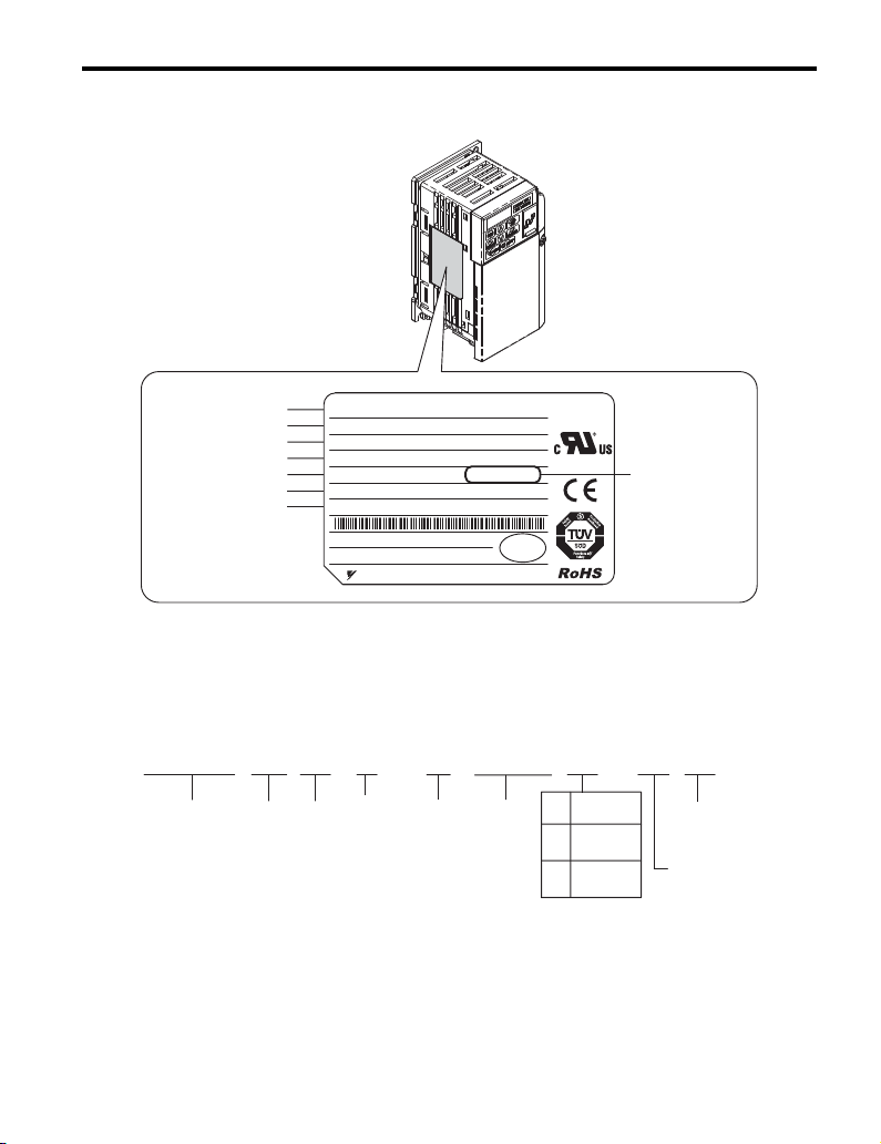
◆ Model Number and Nameplate Check
Please perform the following tasks after receiving the drive:
• Inspect the drive for damage.
• If the drive appears damaged upon receipt, contact the shipper immediately.
• Verify receipt of the correct model by checking the information on the nameplate.
• If you have received the wrong model or the drive does not function properly, contact
your supplier.
6 YASKAWA ELECTRIC TOBP C710606 21E YASKAWA AC Drive - V1000 Finless Installation Guide
Page 7
2 Product Overview
PRG : 1011
CIMR-VA2A0003JAA
YASKAWA ELECTRIC CORPORATION
MADE IN JAPAN
:
: AC3PH 200-240V 50 / 60Hz 2.7A / 1.4A
: AC3PH 0-240V 0-400Hz 1.2A / 0.8A
: 0.6 kg
:
:
: E131457 IP20
PASS
MODEL
MAX APPLI. MOTOR : 0.75kW / 0.4kW REV : A
INPUT
OUTPUT
MASS
O / N
S / N
FILE NO
7J48
AC drive model
Max applicable motor
Input specifications
Output specifications
Mass
Lot number
Serial number
Software version
CIMR-
V
A
2
A
0001
J
A
A
Drive
V1000
Series
Region
Code
Voltage
Class
No.
Enclosure
Type
Environmental
Specification
Design
Revision
Order
Customized
Specification
Finless
(IP20) <1>
J
Finless
(IP00) <1>
L
Unit
No.
■ Nameplate
Figure 1
Figure 1 Nameplate Information
■ Drive Model Identification
The V1000 finless drive type is indicated by the letter “J” or “L” in the AC drive model
designation code. Refer to the Quick Start Guide for complete model number information.
<1> The drive must be installed a control panel with a proper heat sink.
YASKAWA ELECTRIC TOBP C710606 21E YASKAWA AC Drive - V1000 Finless Installation Guide 7
Figure 2 Understanding the Model Number
Page 8

3 Conditions of Acceptability
3 Conditions of Acceptability
Adhere to the installation conditions specified in this guide to take full advantage of the
finless design of this drive.
◆ Installation Environment
The drive must be installed a control panel with a proper heat sink. The drive ambient
temperature shall not exceed 50 ºC (122 ºF) for the drives installed location.
◆ Heatsink Plate Temperature
The aluminum panel on the back of the drive is referred to as the “heatsink plate.” The
heatsink plate temperature should never exceed the following values:
CIMR-VBA, CIMR-V2A0001~0020, CIMR-V4A0001~0011: 90 °C
CIMR-V2A0030~0069, CIMR-V4A0018~0038: 80 °C
Table 6 and Table 7 lists the thermal characteristics of the drive.
Use parameter U4-08 to check the temperature of the heatsink plate as described below.
NOTICE: The drive may be damaged if the temperature of the heatsink plate exceeds specified tolerance
levels (90 °C or 80 °C, depending on the model). Excessive heat can also shorten the performance life of
various drive components.
■ Checking and Monitoring Heatsink Plate Temperature
Checking Heatsink Plate Temperature Using the LED Operator
Scroll to parameter U4-08 (heatsink plate temperature).
When the temperature of the heatsink plate is 89 ºC, U4-08 will display:
Note: Parameter U4-08 is available in drive software version 1011 or later.
Checking Heatsink Plate Temperature Using an Analog Output
Example: When using Multi-Function Analog Output Terminal AM, set the parameters
shown in Tab le 1 .
Table 1 Using Analog Output 1
No. Name Description
H4-01 Analog Output Terminal AM Function Selection
H4-02 Analog Output Terminal AM Gain 100.0%
H4-03 Analog Output Terminal AM Bias 0.0%
8 YASKAWA ELECTRIC TOBP C710606 21E YASKAWA AC Drive - V1000 Finless Installation Guide
00408
(heatsink plate temperature)
Page 9

3 Conditions of Acceptability
0
Output Voltage㧔V㧕
10.0
9.0
5.0
9050 100
Temperature(°C)
Figure 2
Figure 3 Output of Heatsink Plate Temperature by Analog Output
Note: 1. Accuracy of the temperature reading may vary ±5 ºC between 50 and 100 ºC.
2. The heatsink temperature is affected by the ambient temperature. Never exceed the allowable maximum
heatsink plate temperature.
■ Drive Overheat Alarm (oH)
Use parameter L8-02 to cause the drive output an alarm when the heatsink plate exceeds the
specified temperature.
L8-03 determines the action taken by the drive when an oH alarm is triggered. Refer to the
V1000 Technical Manual for more details.
◆ Installation to Metallic Surface
The mating surface shall have the following properties:
• Surface flatness shall not exceed 0.2 mm across the entire mating surface.
• Surface roughness shall not exceed 25 S.
Note: A surface roughness of 25 S means “Ra” (average roughness) is not greater than 6.3 a and “Ry”
(maximum peak) is not greater than 25 μm.
◆ Thermal Compound
Apply a thermal compound between the heatsink plate and the mating surface. The thermal
compound assists in drive heat dissipation.
Yaskawa recommends the thermal compounds in Table 2.
YASKAWA ELECTRIC TOBP C710606 21E YASKAWA AC Drive - V1000 Finless Installation Guide 9
Page 10

3 Conditions of Acceptability
Metal panel
Thermal compound
Heatsink plate
Installation
screws
V1000 Finless
Table 2 Recommended Heatsink Plate Thermal Compounds
Manufacturer Typ e Model Required Amount
Shin-Etsu Chemical Inc.
Dow Corning Toray Inc.
Spread the required amount of thermal compound over the clean heatsink plate. Firmly press
the V1000 finless drive against the metal panel and hold it in place against the heatsink plate
for a few seconds. Wipe away any excess thermal compound from around the heatsink plate
edges.
Figure3
Oil-based
compound
Silicone compound
for heat dissipation
G746
SC4471CV
100 to 250 μm (0.0039 to 0.0098 in)
(Varies in accordance with the flatness
of the metal panel.)
Figure 4 Application of Thermal Compound
Note: Surface milling of the metal panel to within 0.05 mm (0.0019 in) flatness is required if use of
less thermal compound is desired.
Ensure the V1000 finless drive is firmly pressed against the metal panel for a few seconds to
ensure proper thermal transfer.
◆ Drive Heatsink Plate Installation Screw Size and Tightening
Screw size and torque specifications for heatsink plate installation screws that hold the drive
to a metal back panel are listed in Table 3.
10 YA S KA WA EL ECT RIC TOBP C710606 21E YASKAWA AC Drive - V1000 Finless Installation Guide
Torque
Table 3 Screw Size and Tightening Torque
Voltage Class
Single-Phase 200 V class BA0001 ~ BA0012 M4 1.0 to 1.3 (0.74 to 0.96)
CIMR-V
Model
Screw Size
Tightening Torque
Nxm (ft-lbf)
Page 11

3 Conditions of Acceptability
aa
Metal
panel
100 mm
minimum
100 mm
minimum
Voltage Class
Three-phase 200V class
Three-phase 400V class
NOTICE: Tighten all screws according to specified torques. Failure to do so may inhibit drive cooling and
possible damage the drive.
Model
CIMR-V
2A0001 ~ 2A0020 M4 1.0 to 1.3 (0.74 to 0.96)
2A0030 ~ 2A0056 M5 2.0 to 2.5 (1.48 to 1.84)
2A0069 M6 4.0 to 5.0 (2.95 to 3.69)
4A0001 ~ 4A0011 M4 1.0 to 1.3 (0.74 to 0.96)
4A0018 ~ 4A0038 M5 2.0 to 2.5 (1.48 to 1.84)
Screw Size
Tightening Torque
Nxm (ft-lbf)
◆ Installation Spacing
Tabl e 4 illustrates correct installation spacing for proper airflow, and wiring. The drive
should be installed so that the heatsink plate rests flat against the metal back panel to ensure
proper cooling.
Table 4 Correct Installation Spacing
Side Clearance Top/Bottom Clearance
YASKAWA ELECTRIC TOBP C710606 21E YASKAWA AC Drive - V1000 Finless Installation Guide 11
Page 12

3 Conditions of Acceptability
Table 5 Correct Installation Spacing
Voltage Class
Drive Model
CIMR-V
Single-Phase 200 V Class BA0001 to BA0012
Three-Phase 200 V Class 2A0001 to 2A0069
Three-Phase 400 V Class 4A0001 to 4A0038
NOTICE: Do not install V1000 Finless drives using the Side-by-Side method available in standard V1000
drive models. Improper drive cooling may result in damage to the drive. Install V1000 Finless drives with a
minimum side-by-side clearance of 30 mm (1.18 in).
■ Ambient Temperature Derating
Parameters L8-12 (Ambient Temperature Setting) and L8-35 (Installation Method Selection)
must be set according to the installation conditions if the ambient temperature is higher than
35°C. Refer to Figure 5 for drive derating according to ambient temperature.
Parameter L8-12 = 40°C (default). The setting range is -10 to 50°C.
Operating the V1000 Finless drive between -10 and 35°C allows 100% continuous current
without derating. Drive operation between 35 and 50°C requires drive derating according to
Figure 5.
The drive can be used with 100% rating between -10 and 50°C ambient temperature if the
airflow around the unit is 0.5 m/s or more. In this case set L8-35 = 0 (Installation method =
IP20 standard drive).
Figure4
Rating
100%
80%
Side Clearance (a)
mm / (in)
30 / (1.18)
L8-35 = 0
surrounding
airflow of 0.5 m/s
L8-35 = 3 (default)
Finless/External heatsink
0
Figure 5 Ambient Temperature and Drive Derating
12 YA S KA WA EL ECT RIC TOBP C710606 21E YASKAWA AC Drive - V1000 Finless Installation Guide
35°C
50°C
L8-12
Ambient
Temperature
Setting
Page 13

3 Conditions of Acceptability
◆ V1000 Finless Drive Watt Loss Thermal Characteristics
■ Normal Duty
Table 6 Drive Watt Loss (Normal Duty Rating)
200 V Single-Phase Class
Model
CIMR-VBA
Rated Output Current
(A)
Heatsink
Generated
Heat Loss
Rated Output Current
Generated
Heat Loss
Rated Output Current
Generated
Heat Loss
Plate (W)
Internal (W) 8.0 9.7 14.4 19.4 – 29.8 37.1 – – – – – –
Total (W) 13.5 17.3 29.0 49.5 – 81.5 98.4 – – – – – –
Model
CIMR-V2A
(A)
Heatsink
Plate (W)
Internal (W) 8.0 9.5 13.6 17.2 24.0 25.8 30.4 44.1 46.3 85.8 108.6 145.2 185.8
Total (W) 13.0 17.1 29.4 44.7 68.6 77.5 91.7 133.9 145.0 324.0 375.3 503.1 663.1
Model
CIMR-V4A
(A)
Heatsink
Plate (W)
Internal (W) 9.6 13.9 16.8 21.8 – 28.5 31.4 – 46.0 78.4 101.8 139.4 138.8
Total (W) 19.6 32.4 47.3 66.3 – 87.0 95.1 – 127.7 259.6 315.2 426.9 458.0
0001 0002 0003 0006 – 0010 0012 – – – – – –
1.2 1.9 3.3 6.0 – 9.6 12.0 – – – – – –
5.0 7.6 14.6 30.1 – 51.7 61.3 – – – – – –
200 V Three-Phase Class
0001 0002 0004 0006 0008 0010 0012 0018 0020 0030 0040 0056 0069
1.2 1.9 3.5 6.0 8.0 9.6 12.0 17.5 19.6 30.0 40.0 56.0 69.0
5.0 7.6 15.8 27.5 44.6 51.7 61.3 89.8 98.7 238.2 266.7 357.9 477.3
400 V Three-Phase Class
0001 0002 0004 0005 – 0007 0009 – 0011 0018 0023 0031 0038
1.2 2.1 4.1 5.4 – 6.9 8.8 – 11.1 17.5 23.0 31.0 38.0
10.0 18.5 30.5 44.5 – 58.5 63.7 – 81.7 181.2 213.4 287.5 319.2
Note: Carrier frequency is set to 2 kHz.
YASKAWA ELECTRIC TOBP C710606 21E YASKAWA AC Drive - V1000 Finless Installation Guide 13
Page 14

3 Conditions of Acceptability
■ Heavy Duty
Table 7 Drive Watt Loss (Heavy Duty Rating)
200 V Single-PhaseClass
Model
CIMR-VBA
Rated Output Current
(A)
Heatsink
Generated
Heat Loss
Plate (W)
Internal (W) 7.4 8.9 11.5 16.8 – 25.9 34.1 – – – – – –
Total (W) 11.7 16.8 27.6 50.5 – 80.7 104.8 – – – – – –
Model
CIMR-V2A
Rated Output Current
(A)
Heatsink
Generated
Heat Loss
Plate (W)
Internal (W) 7.3 8.8 11.5 15.9 22.2 23.8 30.0 38.8 43.3 68.1 79.6 113.8 156.7
Total (W) 11.6 16.7 27.6 43.3 70.9 78.6 100.7 131.4 153.8 281.4 319.1 461.4 630.6
Model
CIMR-V4A
Rated Output Current
(A)
Heatsink
Generated
Heat Loss
Plate (W)
Internal (W) 11.4 14.9 17.9 26.2 – 30.7 32.9 – 41.5 61.7 75.0 102.1 115.4
Total (W) 30.6 43.8 60.2 96.9 – 111.7 117.5 – 148.7 227.7 282.1 369.0 434.5
<1> Carrier frequency is set to 10 kHZ.
<2> Carrier frequency is set to 8 kHZ.
0001
0002
<1>
0003
<1>
<1>
0.8 1.6 3.0 5.0 – 8.0 11.0 – – – – – –
4.3 7.9 16.1 33.7 – 54.8 70.7 – – – – – –
200 V Three-Phase Class
0001
0002
<1>
0004
<1>
<1>
0.8 1.6 3.0 5.0 6.9 8.0 11.0 14.0 17.5 25.0 33.0 47.0 60.0
4.3 7.9 16.1 27.4 48.7 54.8 70.7 92.6 110.5 213.3 239.5 347.6 473.9
400 V Three-Phase Class
0001
0002
<2>
0004
<2>
<2>
1.2 1.8 3.4 4.8 – 5.5 7.2 – 9.2 14.8 18.0 24.0 31.0
19.2 28.9 42.3 70.7 – 81.0 84.6 – 107.2 166.0 207.1 266.9 319.1
0006
<1>
0006
<1>
0005
<2>
–
0008
<1>
–
0010
<2>
0010
<2>
0007
<2>
0012
––––––
<2>
0012
0018
0020
0030
<2>
0009
<2>
<2>
<2>
0011
–
<2>
<2>
0018
<2>
0040
<2>
0023
<2>
0056
<2>
0031
<2>
0069
<2>
0038
<2>
14 YA S KA WA EL ECT RIC TOBP C710606 21E YASKAWA AC Drive - V1000 Finless Installation Guide
Page 15

4 Periodic Maintenance
4 Periodic Maintenance
◆ Replacement
Estimated drive performance life is based on specific usage conditions. These conditions are
provided for the purpose of maximizing useful drive life and performance. Drive
performance and/or useful life are affected by application in harsh environments or rigorous
use.
■ Conditions for Estimating Performance Life
The estimated performance life of the drive is 10 years under the following conditions:
• Drive ambient temperature: Yearly average of 35°C
• Load factor: 80% max.
• Operation time: 24 hours a day
Drive performance life may be less than 10 years if drive use exceeds the conditions above.
YASKAWA ELECTRIC TOBP C710606 21E YASKAWA AC Drive - V1000 Finless Installation Guide 15
Page 16

5 Dimensions
5 Dimensions
Table 8 V1000 Finless Dimensions for Models BA0001~2A0006 (metric)
Voltage Class
Single-Phase
200 V class
Three-Phase
200 V class
2-M4
H
H1
W1
W
Drive Model
CIMR-V
BA0001 68 128 71 56 118 5 3 0.6
BA0002 68 128 71 56 118 5 3 0.6
BA0003 68 128 81 56 118 5 3 0.8
2A0001 68 128 71 56 118 5 3 0.6
2A0002 68 128 71 56 118 5 3 0.6
2A0004 68 128 71 56 118 5 3 0.7
2A0006 68 128 71 56 118 5 3 0.7
H2
Dimensions (mm)
W H D W1 H1 H2 t1
t1
D
Table 9 V1000 Finless Dimensions for Models BA0001~2A0006 (U.S. units)
Voltage Class
Single-Phase
200 V class
Three-Phase
200 V class
Drive Model
CIMR-V
BA0001 2.68 5.04 2.80 2.21 4.65 0.20 0.12 1.32
BA0002 2.68 5.04 2.80 2.21 4.65 0.20 0.12 1.32
BA0003 2.68 5.04 3.19 2.21 4.65 0.20 0.12 1.76
2A0001 2.68 5.04 2.80 2.21 4.65 0.20 0.12 1.32
2A0002 2.68 5.04 2.80 2.21 4.65 0.20 0.12 1.32
2A0004 2.68 5.04 2.80 2.21 4.65 0.20 0.12 1.54
2A0006 2.68 5.04 2.80 2.21 4.65 0.20 0.12 1.54
W H D W1 H1 H2 t1
Dimensions (in)
Weight
(kg)
Weight
(lb.)
16 YASKAWA ELECTRIC TOBP C710606 21E YASKAWA AC Drive - V1000 Finless Installation Guide
Page 17

5 Dimensions
Table 10 V1000 Finless Dimensions for Models BA0006~4A0009 (metric)
Voltage Class
Single-Phase
200 V class
Three-Phase
200 V class
Three-Phase
400 V class
Drive Model
CIMR-V
4-M4
H
H1
W1
W
H2
Dimensions (mm)
W H D W1 H1 H2 t1
t1
D
BA0006 108 128 79.5 96 118 5 4 1.1
BA0010 108 128 91 96 118 5 4 1.1
2A0008 108 128 71 96 118 5 4 1.0
2A0010 108 128 71 96 118 5 4 1.0
2A0012 108 128 79.5 96 118 5 4 1.0
4A0001 108 128 71 96 118 5 4 0.9
4A0002 108 128 71 96 118 5 4 0.9
4A0004 108 128 79.5 96 118 5 4 1.0
4A0005 108 128 96 96 118 5 4 1.0
4A0007 108 128 96 96 118 5 4 1.1
4A0009 108 128 96 96 118 5 4 1.1
Weight
(kg)
YASKAWA ELECTRIC TOBP C710606 21E YASKAWA AC Drive - V1000 Finless Installation Guide 17
Page 18

5 Dimensions
W
H
W1
H1
H2
D
t1
4-M4
Table 11 V1000 Finless Dimensions for Models BA0006~4A0009 (U.S. units)
Voltage Class
Single-Phase
200 V class
Three-Phase
200 V class
Drive Model
CIMR-V
W H D W1 H1 H2 t1
BA0006 4.26 5.04 3.13 3.78 4.65 0.20 0.16 2.43
BA0010 4.26 5.04 3.59 3.78 4.65 0.20 0.16 2.43
2A0008 4.26 5.04 2.80 3.78 4.65 0.20 0.16 2.20
2A0010 4.26 5.04 2.80 3.78 4.65 0.20 0.16 2.20
2A0012 4.26 5.04 3.13 3.78 4.65 0.20 0.16 2.20
Dimensions (in)
Weight
(lb.)
4A0001 4.26 5.04 2.80 3.78 4.65 0.20 0.16 1.98
4A0002 4.26 5.04 2.80 3.78 4.65 0.20 0.16 1.98
Three-Phase
400 V class
4A0004 4.26 5.04 3.13 3.78 4.65 0.20 0.16 2.20
4A0005 4.26 5.04 3.78 3.78 4.65 0.20 0.16 2.20
4A0007 4.26 5.04 3.78 3.78 4.65 0.20 0.16 2.43
4A0009 4.26 5.04 3.78 3.78 4.65 0.20 0.16 2.43
18 YA S KA WA EL ECT RIC TOBP C710606 21E YASKAWA AC Drive - V1000 Finless Installation Guide
Page 19

5 Dimensions
4-M4
W
W1
H
H1
H2
D
t1
Table 12 V1000 Finless Dimensions for Models BA0012~4A0011(metric)
Voltage Class
Single-Phase
200 V class
Three-Phase
200 V class
Three-Phase
400 V class
Drive Model
CIMR-V
W H D W1 H1 H2 t1
BA0012 140 128 98 128 118 5 4 1.4
2A0018 140 128 78 128 118 5 4 1.3
2A0020 140 128 78 128 118 5 4 1.3
4A0011 140 128 78 128 118 5 4 1.3
Dimensions (mm)
Weight
(kg)
Table 13 V1000 Finless Dimensions for Models BA0012~4A0011 (U.S. units)
Voltage Class
Single-Phase
200 V class
Three-Phase
200 V class
Three-Phase
400 V class
Drive Model
CIMR-V
W H D W1 H1 H2 t1
BA0012 5.52 5.04 3.86 5.04 4.65 0.20 0.16 3.09
2A0018 5.52 5.04 3.07 5.04 4.65 0.20 0.16 2.87
2A0020 5.52 5.04 3.07 5.04 4.65 0.20 0.16 2.87
4A0011 5.52 5.04 3.07 5.04 4.65 0.20 0.16 2.87
YASKAWA ELECTRIC TOBP C710606 21E YASKAWA AC Drive - V1000 Finless Installation Guide 19
Dimensions (in)
Weight
(lb.)
Page 20

5 Dimensions
4-d
W
W1
H
H1
H2
H4
H3
H5
D
t1
Table 14 V1000 Finless Dimensions for Models 2A0030~4A0038 (metric)
Voltage Class
Drive Model
CIMR-V
W H D W1 H1 H2 H3 H4 H5 d t1
Dimensions (mm)
Weight
(kg)
2A0030 140 260 145 122 248 6 234 13 5 M5 5 3.2
Three-Phase
200 V class
2A0040 140 260 145 122 248 6 234 13 5 M5 5 3.2
2A0056 180 300 147 160 284 8 270 15 5 M5 5 4.6
2A0069 220 350 152 192 336 7 320 15 5 M6 5 7.0
4A0018 140 260 145 122 248 6 234 13 5 M5 5 3.1
Three-Phase
400 V class
4A0023 140 260 145 122 248 6 234 13 5 M5 5 3.2
4A0031 180 300 147 160 284 8 270 15 5 M5 5 4.3
4A0038 180 300 147 160 284 8 270 15 5 M5 5 4.6
Table 15 V1000 Finless Dimensions for Models 2A0030~4A0038 (U.S. units)
Voltage
Class
Drive Model
CIMR-V
W H D W1 H1 H2 H3 H4 H5 d t1
2A0030 5.51 10.24 5.71 4.81 9.77 0.24 9.22 0.51 0.20 M5 0.20 7.06
Three-Phase
200 V class
2A0040 5.51 10.24 5.71 4.81 9.77 0.24 9.22 0.51 0.20 M5 0.20 7.06
2A0056 7.09 11.82 5.79 6.30 11.19 0.36 10.64 0.59 0.20 M5 0.20 10.14
2A0069 8.69 13.79 5.99 7.56 13.24 0.28 12.61 0.59 0.20 M6 0.20 15.43
4A0018 5.51 10.24 5.71 4.81 9.77 0.24 9.22 0.51 0.20 M5 0.20 6.83
Three-Phase
400 V class
4A0023 5.51 10.24 5.71 4.81 9.77 0.24 9.22 0.51 0.20 M5 0.20 7.06
4A0031 7.09 11.82 5.79 6.30 11.19 0.36 10.64 0.59 0.20 M5 0.20 9.48
4A0038 7.09 11.82 5.79 6.30 11.19 0.36 10.64 0.59 0.20 M5 0.20 10.14
20 YA S KA WA EL ECT RIC TOBP C710606 21E YASKAWA AC Drive - V1000 Finless Installation Guide
Dimensions (in)
Weight
(lb.)
Page 21

6 Selecting an External Heatsink
6 Selecting an External Heatsink
This section describes the selection of a suitable external heatsink when using a V1000
Finless drive.
◆ Data Required for Heatsink Selection
The table below shows data that are needed to select a heatsink that suits drive and
application.
Symbol Description
Drive heat loss
Refer to V1000 Finless Drive Watt Loss Thermal Characteristics on page 13
the amount of heat loss from the heatsink plate of the drive.
Maximum heatsink plate temperature
This is the temperature at the surface of the heatsink plate. It can be monitored with U4-08. The
maximum allowable value depends on drive model.
CIMR-VBA, CIMR-V2A0001~0020, CIMR-V4A0001~0011: 90°C
CIMR-V2A0030~0069, CIMR-V4A0018~0038: 80°C
External heatsink ambient temperature (air temperature around heatsink)
Heatsink plate thermal resistance
HSP
This value is 0.05 K/W
Thermal resistance between the heatsink plate and the external heatsink
Can be calculated by
d
Rθ
HSP-EHS
=
Comp
A
λ
th
comp
Heat transfer area between drive heatsink plate and external heatsink
Note: Due to uneven heat generation across the heatsink plate (by arrangement
of internal components) the effective area for heat transfer is only ~70% of
A
heatsink plate area. This must be considered when calculating the thermal
th
resistance.
Refer to Dimensions on page 16 for values of H and W to calculate the area of
the heatsink plate.
Thermal conductivity of the heatsink thermal compound
λ
Comp
Thickness of the thermal compound
d
Comp
Thermal resistance of the external heatsink
EHS
to check
T
HSP_max
Rθ
Rθ
Rθ
P
Loss
T
Amb
HSP-EHS
YASKAWA ELECTRIC TOBP C710606 21E YASKAWA AC Drive - V1000 Finless Installation Guide 21
Page 22

6 Selecting an External Heatsink
Rθ
EHS_max
=
T
HSP_max
- T
Amb
P
Loss
- Rθ
HSP
- Rθ
HSP-EHS
(
)
◆ External Heatsink Selection
Figure 6 shows the heat transfer principle from the drive heatsink plate to the heatsink
ambient air.
Figure5
Heatsink plate
Thermal
compound
External
heatsink
Drive
T
HSP
Figure 6 Thermal Equivalent Circuit
For a given ambient temperature the heatsink plate temperature must not exceed the
maximum allowable value. As the Rθ
must be satisfied with proper heatsink selection.
■ Select an External Heatsink by the Thermal Resistance
HSP
Use the formula below to calculate the maximum thermal resistance Rθ
T
Amb
and Rθ
P
Loss
Heatsink plate temperature T
Heatsink plate thermal resistance Rθ
Thermal resistance between heatsink
plate and external heatsink Rθ
External heatsink thermal resistance Rθ
T
Amb
are essentially fixed, this condition
HSP-EHS
HSP-EHS
EHS_max
HSP
HSP
EHS
.
Select a heatsink with a smaller thermal resistance than Rθ
. The heatsink height and
EHS_max
width should be close to the drive dimensions. If the selected heatsink has a thermal
resistance that is too high, then choose a heatsink with a different shape (e.g. longer or more
fins). Compare the actual mounting conditions with the ones mentioned for the Rθ
in the heatsink specifications and apply reduction factors if necessary. Also remember that
the heatsink cooling ability can reduce by time due to dirt.
NOTICE: If the heatsink height and width are much larger than the drive heatsink plate dimensions or if
multiple drives are installed on one heatsink, it may be necessary to apply correction factors to the thermal
resistance value given in the heatsink specification. Consult the heatsink manufacturer.
■ Check the Feasibility of a Given Heatsink
If a heatsink is given or the selection is limited by the installation conditions (space available
etc.) use the formula below to calculate the actual heatsink plate temperature.
T
= P
Loss
Rθ
HSP
If T
is smaller than the maximum allowable heatsink plate temperature, the selected
HSP
heatsink can be used. For verification of temperature, refer to Checking and Monitoring
HSP
+ Rθ
HSP-EHS
+ Rθ
EHS
) + T
Amb
Heatsink Plate Temperature on page 8.
22 YA S KA WA EL ECT RIC TOBP C710606 21E YASKAWA AC Drive - V1000 Finless Installation Guide
EHS
value
Page 23

6 Selecting an External Heatsink
NOTICE: Due to uneven compound thickness, uneven heat generation across the heatsink plate or other
factors, the actual heatsink plate temperature (monitored in U4-08) can be slightly different from the
calculated value. An oH drive fault may occur if the heatsink plate temperature exceeds the maximum
allowable value.
◆ Heatsink Selection Example
This example shows heatsink selection for a CIMR-V2A0006 drive in Normal Duty (ND)
mode.The data required are listed in the table below.
Item Value
HSP
HSP-EHS
27.5 W
90°C
40°C
0.05 K/W
H = 128 mm, D = 68 mm,
A
th
= 0.7 x 0.128 m x 0.068 m = 6.1 x 10⁻³ m
A
th
2
0.8 W/(mxK)
λ
Thermal conductivity of “Thermal Compound G746” (Shin-Etsu Chemical Co.,
Comp
Ltd)
Recommended compound thickness: 100 μm
d
Comp
Rθ
HSP_EHS
=
0.8 W/(mK) × 6.1 × 10
100 μm
-3 m2
= 0.02 K/W
P
Loss
T
HSP_max
T
Amb
Rθ
Rθ
YASKAWA ELECTRIC TOBP C710606 21E YASKAWA AC Drive - V1000 Finless Installation Guide 23
Page 24

6 Selecting an External Heatsink
Rθ
EHS_max
=
90 - 40
27.5 W
- 0.05 K/W - 0.02 K/W
()
= 1.74 K/W
T
HSP
= 27.5 W 0.05 K/W + 0.02 K/W + 1.6 K/W) + 40= 85.9
■ Heatsink Selection by Thermal Resistance
Substituting the example values into the formula gives:
The heatsink must have a thermal resistance lower than 1.7 K/W. When selecting the
heatsink apply a safety margin to the calculated value in order to ensure tripless drive
operation, even if the installation conditions change (temporary higher temperature, loss of
cooling ability of the external heatsink due to dust, etc.).
■ Feasibility Check of a Selected Heatsink
If for example a heatsink with Rθ
The selected heatsink can be used, but considering that the heatsink area is probably larger
than the drive footprint and the ambient conditions could change (reduced heatsink cooling
ability by dirt, etc.), a heatsink with a lower Rθ
= 72.2°C) should be chosen.
= 1.6 K/W is selected, the heatsink temperature will be:
EHS
EHS
(e.g. Rθ
= 1.1 K/W, resulting in T
EHS
HSP
24 YA S KA WA EL ECT RIC TOBP C710606 21E YASKAWA AC Drive - V1000 Finless Installation Guide
Page 25

7 Revision History
MANUAL NO.ޓTOBP C710606 21B
Published in Japan July 2007 07-4
Date of publication
Date of original publication
1
Place of publication
Revision number
1110987654321
7 Revision History
The revision dates and the numbers appear on the bottom of the back cover.
Date of
Publication
January 2013 Back cover Revision: Address
December 2011 Back cover Revision: Address
November 2011 All Chapters Corrections: Reviewed and corrected entire documentation.
June 2011
September 2010 Chapter 3 Revision: Thermal Compound
July 2010 Back cover Revision: Address
December 2009
July 2008 Back cover Revision: Revision number
June 2008
March 2008
July 2007
April 2007 −− First edition
YASKAWA ELECTRIC TOBP C710606 21E YASKAWA AC Drive - V1000 Finless Installation Guide 25
Rev. No. Section Revised Content
Front cover,
back cover
Revision
History
Chapter 1 Corrections: Drive Model Identification
Chapter 2 Corrections: Installation Enviroment
All Chapters
Chapter 2
Chapter 3 New: Maintenance information
Chapter 6 Revision: Selecting an External Heatsink
Chapter 2
Chapter 4 Addition: Selecting an External Heatsink
Revision: Format
Revision: Example of the revision dates and the numbers
New: Protective enclosure data (IP00) New models:
3-phase 200 V: CIMR-V2A0030 - 2A0069
3-phase 400 V: CIMR-V4A0018 - 4A0038
Corrections: Settings for H4-01 in Table 1.
New: Warning for the heatsink plate temperature Overheat
prealarm
Addition: Checking the Temperature of Heatsink Plate of
Drive (software version 1011 or later)
Page 26

YASKAWA AC Drive - V1000
Compact Vector Control Drive
Finless Type Installation Guide
DRIVE CENTER (INVERTER PLANT)
2-13-1, Nishimiyaichi, Yukuhashi, Fukuoka, 824-8511, Japan
Phone: 81-930-25-3844 Fax: 81-930-25-4369
http://www.yaskawa.co.jp
YASKAWA ELECTRIC CORPORATION
New Pier Takeshiba South Tower, 1-16-1, Kaigan, Minatoku, Tokyo, 105-6891, Japan
Phone: 81-3-5402-4502 Fax: 81-3-5402-4580
http://www.yaskawa.co.jp
YASKAWA AMERICA, INC.
2121 Norman Drive South, Waukegan, IL 60085, U.S.A.
Phone: (800) YASKAWA (927-5292) or 1-847-887-7000 Fax: 1-847-887-7310
http://www.yaskawa.com
YASKAWA ELÉTRICO DO BRASIL LTDA.
Avenda Fagundes Filho, 620 Bairro Saude, São Paulo, SP04304-000, Brazil
Phone: 55-11-3585-1100
http://www.yaskawa.com.br
YASKAWA EUROPE GmbH
Hauptstrasse 185, 65760 Eschborn, Germany
Phone: 49-6196-569-300 Fax: 49-6196-569-398
http://www.yaskawa.eu.com
YASKAWA ELECTRIC UK LTD.
1 Hunt Hill Orchardton Woods, Cumbernauld, G68 9LF, United Kingdom
Phone: 44-1236-735000
http://www.yaskawa.co.uk
YASKAWA ELECTRIC KOREA CORPORATION
9F, Kyobo Securities Bldg., 26-4, Yeouido-dong, Yeongdeungpo-gu, Seoul, 150-737, Korea
Phone: 82-2-784-7844
http://www.yaskawa.co.kr
YASKAWA ELECTRIC (SINGAPORE) PTE. LTD.
151 Lorong Chuan, #04-01, New Tech Park, 556741, Singapore
Phone: 65-6282-3003
http://www.yaskawa.com.sg
YASKAWA ELECTRIC (CHINA) CO., LTD.
12F, Carlton Bld., No.21 HuangHe Road, HuangPu District, Shanghai 200003, China
Phone: 86-21-5385-2200
http://www.yaskawa.com.cn
YASKAWA ELECTRIC (CHINA) CO., LTD. BEIJING OFFICE
Room 1011, Tower W3 Oriental Plaza, No. 1 East Chang An Ave.,
Dong Cheng District, Beijing, 100738, China
Phone: 86-10-8518-4086
YASKAWA ELECTRIC TAIWAN CORPORATION
9F, 16, Nanking E. Rd., Sec. 3, Taipei, 104, Taiwan
Phone: 886-2-2502-5003
YASKAWA ELECTRIC INDIA PRIVATE LIMITED
#17/A Electronics City, Hosur Road Bangalore 560 100 (Karnataka), India
Phone: 91-80-4244-1900
http://www.yaskawaindia.in
Fax: 55-11-5581-8795
Fax: 44-1236-458182
Fax: 82-2-784-8495
Fax: 65-6289-3003
Fax: 86-21-5385-3299
Fax: 86-10-8518-4082
Fax: 886-2-2505-1280
Fax: 91-80-4244-1901
YASKAWA ELECTRIC CORPORATION
In the event that the end user of this product is to be the military and said product is to be employed in any weapons systems or the manufacture
thereof, the export will fall under the relevant regulations as stipulated in the Foreign Exchange and Foreign Trade Regulations. Therefore, be sure
to follow all procedures and submit all relevant documentation according to any and all rules, regulations and laws that may apply.
Specifications are subject to change without notice for ongoing product modifications and improvements.
© 2007-2013 YASKAWA ELECTRIC CORPORATION. All rights reserved.
MANUAL NO. TOBP C710606 21E
Published in Japan January 2013 07-4
12-7-9
11
-0
 Loading...