

Page 1
YASKAWA AC Drive-V1000 Option
DI-100 120 Vac Interface
Option
Installation Manual
PCB PN: UTC000400
To properly use the product, read this manual thoroughly and retain
for easy reference, inspection, and maintenance. Ensure the end user
receives this manual.
MANUAL NO. TOEP YEAOPT 03
Page 2

This Page Intentionally Blank
Copyright 2009 YASKAWA ELECTRIC AMERICA, INC. All rights reserved.
All rights reserved. No part of this publication may be reproduced, stored in a retri eval system, or transmitted, in any form or by any
means, mechanical, electronic, photocopying, recording, or otherwise, without the prior written permission of Yaskawa. No patent liability
is assumed with respect to the use of the information contained herein. Moreove r, because Yaskawa is constantly striving to improve its
high-quality products, the information contained in this manual is subject to cha nge without notice. Every precaution has been taken in the
preparation of this manual. Yaskawa assumes no responsibility for errors or omissio ns. Neither is any liability assumed for damages
resulting from the use of the information contained in this publication
2 YASKAWA ELECTRIC TOEP YEAOPT 03 - V1000 Option DI-100 120 Vac Interface Installation Manual
Page 3

Table of Contents
1 PREFACE AND SAFETY . . . . . . . . . . . . . . . . . . . . . . . . . . . .5
2 PRODUCT OVERVIEW . . . . . . . . . . . . . . . . . . . . . . . . . . . . . . 8
3 RECEIVING . . . . . . . . . . . . . . . . . . . . . . . . . . . . . . . . . . . . . . . 9
4 OPTION COMPONENTS. . . . . . . . . . . . . . . . . . . . . . . . . . . . 10
5 INSTALLATION PROCEDURE . . . . . . . . . . . . . . . . . . . . . . . 12
6 TROUBLESHOOTING. . . . . . . . . . . . . . . . . . . . . . . . . . . . . . 23
7 OPTION SPECIFICATIONS . . . . . . . . . . . . . . . . . . . . . . . . .24
YAS KAWA ELE CTR IC TOEP YEAOPT 03 - V1000 Option DI-100 120 Vac Interface Installation Manual 3
Page 4

This Page Intentionally Blank
4 YASKAWA ELECTRIC TOEP YEAOPT 03 - V1000 Option DI-100 120 Vac Interface Installation Manual
Page 5
1 Preface and Safety
STOP
(Hz)
(Hz)
(A)
(V)
V1000
ᵄᢙᜰ
ᱜォㅒォㆬᛯ
ജᵄᢙ
ജ㔚ᵹ
ജ㔚
ࡕ࠾࠲
ࡌࡈࠔࠗ
࠶࠻ࠕ࠶ࡊ
ࡄࡔ࠲⸳ቯ
ࠝ࠻࠴ࡘ࠾ࡦࠣ
ᝪ߃ઃߌޔㆇォߩ೨ߦߪᔅߕขᛒ⺑ᦠࠍ⺒ߎߣޕ
ㅢ㔚߅ࠃ߮㔚Ḯㆤᢿᓟ
5
ಽએౝߪࡈࡠࡦ࠻ࠞࡃࠍ
ᄖߐߥߎߣޕ
400V
⚖ࠗࡦࡃ࠲ߩ႐วߪޔ㔚Ḯߩᕈὐ߇ធ
ߐࠇߡࠆߎߣࠍ⏕ߔࠆߎߣޕ㧔ޓޓኻᔕ㧕
ߌ߇㧚ᗵ㔚ߩ߅ߘࠇ߇ࠅ߹ߔޕ
ෂޓ㒾
1 Preface and Safety
Yaskawa manufactures products used as components in a wide variety of industrial systems
and equipment. The selection and application of Yaskawa products remain the responsibility
of the equipment manufacturer or end user. Yaskawa accepts no responsibility for the way its
products are incorporated into the final system design. Under no circumstances should any
Yaskawa product be incorporated into any product or design as the exclusive or sole safety
control. Without exception, all controls should be designed to detect faults dynamically and
fail safely under all circumstances. All systems or equipment designed to incorporate a
product manufactured by Yaskawa must be supplied to the end user with appropriate
warnings and instructions as to the safe use and operation of that part. Any warnings
provided by Yaskawa must be promptly provided to the end user. Yaskawa offers an express
warranty only as to the quality of its products in conforming to standards and specifications
published in the Yaskawa manual. NO OTHER WARRANTY, EXPRESSED OR IMPLIED,
IS OFFERED. Yaskawa assumes no liability for any personal injury, property damage,
losses, or claims arising from misapplication of its products.
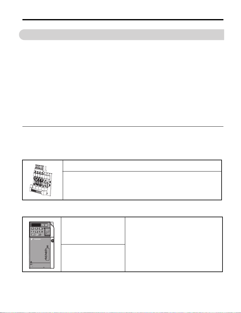
◆ Applicable Documentation
The following manuals are available for the option and drive:
Option
Yaskawa AC Drive -V1000 Option DI-100 120 Vac Interface Installation Manual
Manual No: TOEP YEAOPT 03
Read this manual first.
The installation manual is packaged with the DI-100 120 Vac Interface Option and contains
installation procedures and precautions.
Yaskawa Drive
Yaskawa AC Drive-V1000
Quick Start Guide
Manual No: TOEP C710606 14
Yaskawa AC Drive-V1000
Technical Manual
Manual No: SIEP C710606 18
YASKAWA ELECTRIC TOEP YEAOPT 03 - V1000 Option DI-100 120 Vac Interface Installation Manual 5
To obtain instruction manuals for Yaskawa products
access this site:
U.S.: http://www.yaskawa.com
For questions, contact the local Yaskawa sales office or
the nearest Yaskawa representative.
Page 6
1 Preface and Safety
DANGER
W ARNING
CAUTION
NOTICE
◆ Terms
Note: Indicates a supplement or precaution that does not cause drive damage.
Drive: Yaskawa AC Drive-V1000 Series.
Option: Yaskawa AC Drive-V1000 DI-100 120 Vac Interface Option.
◆ Registered Trademarks
• All trademarks are the property of their respective owners.
◆ Supplemental Safety Information
Read and understand this manual before installing, operating, or servicing this option unit.
The option unit must be installed according to this manual and local codes.
The following conventions are used to indicate safety messages in this manual. Failure to
heed these messages could result in serious or possibly even fatal injury or damage to the
products or to related equipment and systems.
Indicates a hazardous situation, which, if not avoided, will result in death or serious
injury.
Indicates a hazardous situation, which, if not avoided, could result in death or
serious injury.
Indicates a hazardous situation, which, if not avoided, could result in minor or
moderate injury.
Indicates an equipment damage message.
6 YASKAWA ELECTRIC TOEP YEAOPT 03 - V1000 Option DI-100 120 Vac Interface Installation Manual
Page 7
1 Preface and Safety
NOTICE
■ General Safety
General Precautions
• The diagrams in this section may include option units and drives without covers or safety shields to illustrate
details. Be sure to reinstall covers or shields before operating any devices. The option should be used according to
the instructions described in this manual.
• Any illustrations, photographs, or examples used in this manual are provided as examples only and may not apply
to all products to which this manual is applicable.
• The products and specifications described in this manual or the content and presentation of the manual may be
changed without notice to improve the product and/or the manual.
• When ordering a new copy of the manual due to damage or loss, contact your Yaskawa representative or the nearest
Yaskawa sales office and provide the manual number shown on the front cover.
DANGER
Heed the safety messages in this manual.
Failure to comply will result in death or serious injury.
The operating company is responsible for any injuries or equipment damage resulting
from failure to heed the warnings in this manual.
Do not expose the drive to halogen group disinfectants.
Failure to comply may cause damage to the electrical components in the option unit.
Do not pack the drive in wooden materials that have been fumigated or sterilized.
Do not sterilize the entire package after the product is packed.
Do not modify the drive circuitry.
Failure to comply could result in damage to the drive and will void warranty.
Yaskawa is not responsible for any modification of the product made by the user. This
product must not be modified.
YASKAWA ELECTRIC TOEP YEAOPT 03 - V1000 Option DI-100 120 Vac Interface Installation Manual 7
Page 8
2 Product Overview
2 Product Overview
◆ About This Product
The DI-100 option has seven optically isolated input terminals which can be used to connect
external 120 Vac control circuitry to the V1000 drive. The DI-100 Option mounts directly to
the V1000 control board terminals (S1 ~ S7 and SC). This option makes it possible to
control the V1000 digital inputs with 120 Vac.
This manual explains the handling, installation and specifications of this product.
Note: With this option is installed, safety input terminals H1 and HC on the V1000 drive are designed
to the functionality but are not certified to EN61800-5-1, EN954-1/ISO13849 Category 3, IEC/
EN61508 SIL2, Insulation cooridination: Class 1.
◆ Applicable Models
This option can be used with the drive models in Table 1.
Table 1 Applicable Models
Drive Models Model Notes
CIMR-VUBA0001~BA0003
CIMR-VU2A0001~2A0006
CIMR-VUBA0006 thru BA0018
CIMR-VU2A0010 thru 2A0020
CIMR-VU4A0001 thru 4A0011
CIMR-VU2A0030 thru CIMR-VU2A0069
CIMR-VU4A0018 thru CIMR-VU4A0038
<1> Because the bottom cover/conduit bracket is discarded for DI-100 installation, the enclosure rating of these
models becomes IP00 or NEMA Open Type after DI-100 option installation.
1-phase 200 V
and 3-phase 200 V
(small frame)
1- phase 200 V
3-phase 200/400 V
(medium frame)
3-phase 200/400 V
(large frame)
<1>
<1>
8 YASKAWA ELECTRIC TOEP YEAOPT 03 - V1000 Option DI-100 120 Vac Interface Installation Manual
Page 9
3 Receiving
3 Receiving
Please perform the following tasks after receiving the option.
• All equipment is tested against defects at the factory. Immediately report any damages or
shortages evident when the equipment is received to the commercial carrier who
transported the equipment.
• Verify receipt of the correct model by checking the information on the nameplate (see
Figure 1).
• If you have received the wrong model or the option does not function properly, contact
your supplier.
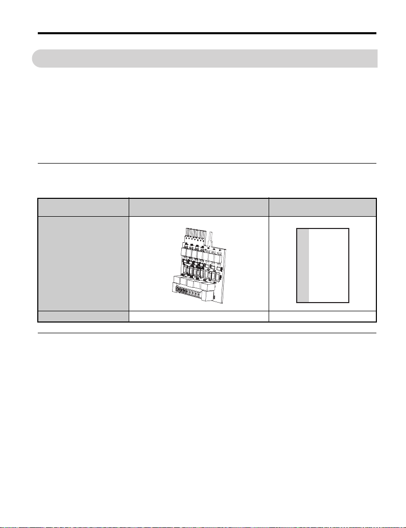
◆ Contents and Packaging
Table 2 Option Package Contents
Description:
_
Quantity: 1 1
DI-100 120 Vac Interface Card
UTC000400
DI-100 Installation Manual
MANUAL
◆ Tool Requirements
A flat blade screwdriver (#1) with a blade thickness of 0.4 mm or less and a blade width of
2.5 mm or less is required to install the option.
YASKAWA ELECTRIC TOEP YEAOPT 03 - V1000 Option DI-100 120 Vac Interface Installation Manual 9
Page 10

4 Option Components
4 Option Components
◆ DI-100 Option
Figure 1
B
C
A
A – DI-100 120 V Interface Card
UTC000400
B – Option terminals (to drive)
Figure 1 DI-100 Option
C – Option terminal block
(to control wiring)
◆ Option Terminal Block
An 8-position terminal block is provided for the connection of control wires.
10 YASKAWA ELECTRIC TOEP YEAOPT 03 - V1000 Option DI-100 120 Vac Interface Installation Manual
Page 11

4 Option Components
X2
S1
S2
S3
S4 S5 S6
S7
Table 3 Option Terminal Functions
Terminal Functions
D1-100 Option Terminal Block Terminal Sig nal Function Description
Forward Run /
S1
Stop
<1>
Reverse Run /
S2
Stop
<1>
Multi-function
S3
S4
S5
S6
S7
X2 Common
<1> Parameter functions and defaults change based on drive programming.
<1>
Input
Multi-function
<1>
Input
Multi-function
<1>
Input
Multi-function
Input
<1>
Multi-function
<1>
Input
Forward run when
closed, stop when
open.(H1-01)
Reverse run when
closed, stop when open
(H1-02)
Multi-function contact
inputs
(H1-03 to H1-07)
Control Input
Common
Signal
Level
120 Vac
±10 %
YASKAWA ELECTRIC TOEP YEAOPT 03 - V1000 Option DI-100 120 Vac Interface Installation Manual 11
Page 12

5 Installation Procedure
W ARNING
5 Installation Procedure
◆ Section Safety
DANGER
Electrical Shock Hazard
Do not connect or disconnect wiring while the power is on.
Failure to comply will result in death or serious injury.
Disconnect all power to the drive, wait at least five minutes after all indicators are off,
measure the DC bus voltage to confirm safe level, and check for unsafe voltages before
servicing to prevent electric shock. The internal capacitor remains charged even after the
power supply is turned off. The charge indicator LED will extinguish when the DC bus
voltage is below 50 Vdc.
Electrical Shock Hazard
Do not remove option board cover while the power is on.
Failure to comply could result in death or serious injury.
The diagrams in this section may include option units and drives without covers or safety
shields to show details. Be sure to reinstall covers or shields before operating any devices.
The option board should be used according to the instructions described in this manual.
Do not allow unqualified personnel to use equipment.
Failure to comply could result in death or serious injury.
Maintenance, inspection, and replacement of parts must be performed only by authorized
personnel familiar with installation, adjustment, and maintenance of this product.
Do not remove option cover while the power to the drive is on.
Failure to comply could result in death or serious injury.
12 YASKAWA ELECTRIC TOEP YEAOPT 03 - V1000 Option DI-100 120 Vac Interface Installation Manual
Page 13

5 Installation Procedure
NOTICE
W ARNING
Do not use damaged wires, place excessive stress on wiring, or damage the wire
insulation.
Failure to comply could result in death or serious injury.
Fire Hazard
Tighten all terminal screws to the specified tightening torque.
Loose electrical connections could result in death or serious injury by fire due to
overheating of electrical connections.
Damage to Equipment
Observe proper electrostatic discharge (ESD) procedures when handling the option
unit, drive, and circuit boards.
Failure to comply may result in ESD damage to circuitry.
Never shut the power off while the drive is outputting voltage.
Failure to comply may cause the application to operate incorrectly or damage the drive.
Do not operate damaged equipment.
Failure to comply may cause further damage to the equipment.
Do not connect or operate any equipment with visible damage or missing parts.
Do not use unshielded cable for control wiring.
Failure to comply may cause electrical interference resulting in poor system performance.
Use shielded twisted-pair wires and ground the shield to the ground terminal of the drive.
YASKAWA ELECTRIC TOEP YEAOPT 03 - V1000 Option DI-100 120 Vac Interface Installation Manual 13
Page 14

5 Installation Procedure
NOTICE
Properly connect all pins and connectors.
Failure to comply may prevent proper operation and possibly damage equipment.
Check wiring to ensure that all connections are correct after installing the option
unit and connecting any other devices.
Failure to comply may result in damage to the option unit.
◆ Prior to Installing the Option Unit
Prior to installing the option, wire the drive and make necessary connections to the drive
terminals. Refer to the drive Quick Start Guide for information on wiring and connecting the
drive. First, verify that the drive functions normally without the option installed.
◆ Installing the Option Unit
Remove the front cover of the drive before installing the option. Follow the directions below
for proper installation.
1. Disconnect all electrical power to the drive.
DANGER! Electrical Shock Hazard - Do not connect or disconnect wiring while the power is on. Failure to
comply will result in death or serious injury. Before installing the option, disconnect all power to the drive.
The internal capacitor remains charged even after the power supply is turned off. The charge indicator LED
will extinguish when the DC bus voltage is below 50 Vdc. To prevent electric shock, wait at least five minutes
after all indicators are off and measure the DC bus voltage level to confirm safe level.
Figure 2
Figure 2 Remove Front Cover
2. For certain models remove the bottom cover or conduit brackets and discard. Refer to step
10 on page 20 for which models prohibit cover reinstallation with the DI-100 option.
14 YASKAWA ELECTRIC TOEP YEAOPT 03 - V1000 Option DI-100 120 Vac Interface Installation Manual
Page 15

5 Installation Procedure
Figure 3
Figure 3 Remove Bottom cover
Note: Cover removal steps for larger models of V1000 with a Terminal Cover:
-Single-Phase 200 V Class: CIMR-VUBA0006 to BA0018
-Three-Phase 200 V Class: CIMR-VU2A0008 to 2A0069
-Three-Phase 400 V Class: All models
Note: Remove the terminal cover before removing the bottom cover to install the option. If the drive is
a NEMA Type 1 enclosure, then remove the lower conduit brackets.
Lower conduit bracket removal is not required for these larger models.
-200 V CIMR-VU2A0030F thru CIMR-VU2A0069F
Figure 4
-400 V CIMR-VU4A0018F thru CIMR-VU4A0038F
Figure 4 Models with Terminal Cover
3. Verify that the red color “CHARGE” indicator lamp (LED) inside the drive is off. It may take
as long as 10 min for the charge on the DC bus capacitors to drop to a safe level
4. Use a voltmeter to verify that the voltage at the incoming power terminals (R/L1, S/L2 and
T/L3) is not present and removed by disconnecting means.
5. Loosen terminals S1 ~ S7 and SC on V1000 drive control wiring terminal block TB1-1.
YASKAWA ELECTRIC TOEP YEAOPT 03 - V1000 Option DI-100 120 Vac Interface Installation Manual 15
Page 16

5 Installation Procedure
Figure 5
Figure 5 Loosen Drive Control Terminals S1 ~ S7 and SC
6. Remove the 120 Vac Interface Card from the ESD bag.
NOTICE: When handling printed circuit boards (PCB’s) always use electrostatic discharge (ESD) protection.
Keep the boards in the ESD bag as long as you can. Do not lay the board on any surfaces without the ESD
protection. When handling, always hold the board from the edges and do not touch the components. Before
installing this option, a technically qualified individual, familiar with this type of equipment and the hazards
involved, should read this entire installation guide.
Figure 6
Figure 6 Remove DI-100 Option from ESD Bag
16 YASKAWA ELECTRIC TOEP YEAOPT 03 - V1000 Option DI-100 120 Vac Interface Installation Manual
Page 17

5 Installation Procedure
Preparing
wire ends
E
A
B
D
C
X2 S1 S2 S3 S4 S5 S6 S7
7. Prepare external 120 Vac control circuit wires (customer wiring) for terminals S1 ~ S7, X2
on the DI-100 option. Prepare the wire ends using Table 4 and Figure 7 as a guide.
NOTICE: Wires to the option should be stripped according to Figure 7 for maximum system safety. Use of
ferrules on the wire ends are recommended.
Table 4 Terminal and Wire Specifications
Terminal and Wire Specifications
Terminal Symbols Ter min al S c re w
S1 ~ S7, X2 M2 1.9 to 2.2 26 to 16 18 / 16
Figure 7
DI-100 Option
Tightening Torque
(in-lbs)
Control Wiring
(AWG)
Recommended
(AWG)
A – DI-100 terminal block D – Loosen screw to insert wire.
B – Avoid fraying wire strands
C – Single wire or stranded wire
8. Connect the prepared customer wiring to the DI-100 terminal block as shown in Figure 7
and Figure 8. Refer to Table 4 for tightening torque. Figure 9 is an example of a wiring
diagram showing customer interface circuitry.
YASKAWA ELECTRIC TOEP YEAOPT 03 - V1000 Option DI-100 120 Vac Interface Installation Manual 17
when stripping insulation from
wire. Strip length 5.08 mm (0.2
in) ±20%
Figure 7 DI-100 Terminal Wiring Guide
E – Blade depth:
0.4 mm (.0157 in) or less
Blade width:
2.5 mm (.089 in) or less
Page 18

5 Installation Procedure
DI-100 Option
120 Vac External
Control Wirin g
Figure 8
Figure 8 120 Vac External Control Wiring (customer wiring) to DI-100 Option
FWD
REV
S3
S4
S5
S6
S7
120 VAC
X2X1
INTERFACE
120 VAC
CARD
X2
S1
S2
S3
S4
S5
S6
S7
Yaskawa V1000
AC Drive
SC C ommon
S1 Forward run/stop
S2 Reverse run/stop
S3 External fault
S4 Fault reset
Multi-step speed 1
S
5
mail/aux switch
S6 Multi-step speed 2
S7 Jog reference
Figure 9 Wiring Diagram Example
18 YASKAWA ELECTRIC TOEP YEAOPT 03 - V1000 Option DI-100 120 Vac Interface Installation Manual
Page 19

5 Installation Procedure
V1000 Drive Terminals
DI-100 Option
120 Vac External
Control Wirin g
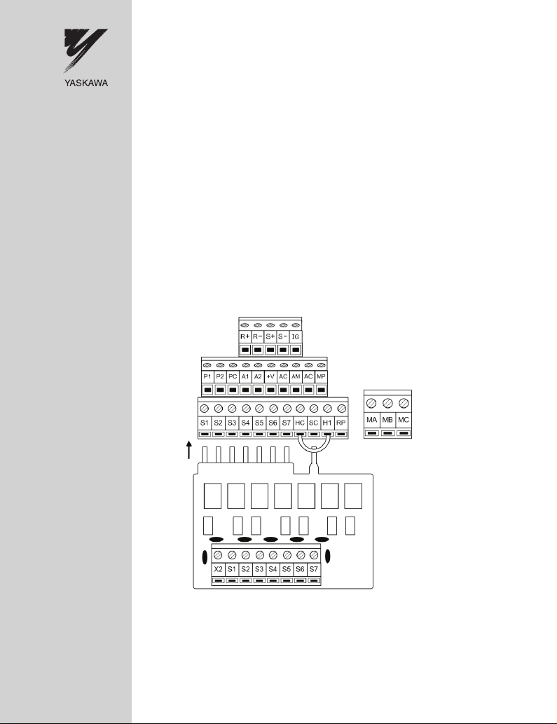
Connect the DI-100 to the V1000 drive.
The DI-100 option connects to V1000 drive terminals S1 ~ S7 and SC. External 120 Vac
input devices can then connect to terminals S1 ~ S7 and X2 on the DI-100 option.
Figure 10 shows the control terminal arrangement for the V1000 drive with the DI-100
option.
Figure 9
Figure 10 Terminal Connections
9. Insert the DI-100 Option into the V1000 drive control terminals S1 ~ S7, and SC. Secure
the DI-100 option board by tightening the V1000 terminals. Refer to the V1000 Quick Start
Guide TOEPC71060614, for recommended tightening torque.
YASKAWA ELECTRIC TOEP YEAOPT 03 - V1000 Option DI-100 120 Vac Interface Installation Manual 19
Page 20

5 Installation Procedure
REMOVE and
discard this
cover
1
Reinstall
Note 1:
The drive enclosure rating
now becomes IP00/Open Type
with this cover removed.
IP20/Open Type
NEMA Type 1
REMOVE and
discard these
covers
1
Note 1:
The drive enclosure rating
now becomes IP00/Open Type
with this cover removed.
Reinstall
10. Reinstall the front cover(s). NOTE: Cover installation is model dependant.
Use Table 5 and associated figures as a guide to determine which drive models prohibit
bottom cover/conduit bracket reinstallation.
Table 5 Drive Cover Installation
Drive Models See Figure Model Notes
CIMR-VUBA0001~BA0003
CIMR-VU2A0001~2A0006
CIMR-VUBA0006 thru BA0018
CIMR-VU2A0010 thru 2A0020
IP20/Open
IP20/NEMA Type 1
Figure 11
IP20/Open - Figure 12
IP20/NEMA Type 1- Figure 13
CIMR-VU4A0001 thru 4A0011
CIMR-VU2A0030 thru CIMR-VU2A0069
CIMR-VU4A0018 thru CIMR-VU4A0038
<1> Because the bottom cover/conduit bracket is discarded for DI-100 installation, the enclosure rating of these
models becomes IP00 or NEMA Open Type after DI-100 option installation.
NOTICE: Some V1000 models will not allow the bottom conduit covers to be reinstalled. Discard covers
specified in Figures 11 thru 15 after DI-100 installation is complete.
Figure 10
IP20/Open - Figure 14
IP20/NEMA Type 1 - Figure 15
1-phase 200 V
and 3-phase 200 V
(small frame)
1- phase 200 V
3-phase 200/400 V
(medium frame)
3-phase 200/400 V
(large frame)
<1>
<1>
Figure 11 Cover Installation on Models
CIMR-VUBA0001 thru BA0003
CIMR-VU2A0001 thru 2A0006
20 YASKAWA ELECTRIC TOEP YEAOPT 03 - V1000 Option DI-100 120 Vac Interface Installation Manual
Page 21

Figure 11
REMOVE and discard
this cover
Reinstall
Reinstall
Note:
The drive enclosure rating
now becomes IP00/Open Type
with this cover removed.
REMOVE and discard
this cover
Reinstall
Reinstall
Note:
The drive enclosure rating
now becomes IP00/Open Type
with these covers removed.
REMOVE and discard
this cover
Figure 12
5 Installation Procedure
Figure 12 Cover Installation on IP20/Open Type Models
CIMR-VUBA0006 thru BA0018
CIMR-VU2A0010 thru 2A0020
CIMR-VU4A0001 thru 4A0011
Figure 13 Cover Installation on IP20/NEMA Type 1 Models
CIMR-VUBA0006 thru BA0018
CIMR-VU2A0010 thru 2A0020
CIMR-VU4A0001 thru 4A0011
YASKAWA ELECTRIC TOEP YEAOPT 03 - V1000 Option DI-100 120 Vac Interface Installation Manual 21
Page 22

5 Installation Procedure
Reinstall
Reinstall
Reinstall
Reinstall
Figure 13
Figure 14 Cover Installation on IP20/Open Type Models
200 V CIMR-VU2A0030B thru CIMR-VU2A0069B
Figure 14
400 V CIMR-VU4A0018B thru CIMR-VU4A0038B
Figure 15 Cover Installation on IP20/NEMA Type 1 Models
200 V CIMR-VU2A0030F thru CIMR-VU2A0069F
400 V CIMR-VU4A0018F thru CIMR-VU4A0038F
11. This completes the installation procedure.
22 YASKAWA ELECTRIC TOEP YEAOPT 03 - V1000 Option DI-100 120 Vac Interface Installation Manual
Page 23

6 Troubleshooting
6 Troubleshooting
Troubleshooting tips are provided below. Verify these points if the drive is not behaving as
expected after installing the option:
• Verify all wire connections are tight.
• Verify all PCB Fingers are fully inserted into the V1000 drive terminals and the terminals
are fully tightened.
• Verify the signal is present at the option terminal by using a Volt Meter to measure the
input signal with respect to the X2 terminal.
• Verify the input is recognized by the drive by viewing Input Terminal Status monitor
parameter U1-10.
• Verify the drive Multi-Function Digital Input parameters (H1-01 through H1-07) of the
drive are set correctly for the expected S1~S7 input terminal behavior.
YASKAWA ELECTRIC TOEP YEAOPT 03 - V1000 Option DI-100 120 Vac Interface Installation Manual 23
Page 24

7 Option Specifications
7 Option Specifications
Specification Data
Inputs 7 + 1 Neutral
Input Impedance, Nominal 10K ohms
On-State Voltage 93 to 132 Vac (110/120 Vac +10% / -15%)
On-State Current, Nominal 14 mA @ 120 Vac
Off-State Voltage, Maximum 19 Vac
Off-State Leakage Current, Maximum 2.5 mA
Operating Frequency 47 to 63 Hz (50/60 Hz +/15%)
On-State Response Time, Maximum 50 ms
Off-State Response Time, Maximum 50 ms
Terminal Wiring AWG 16 to AWG 26
24 YASKAWA ELECTRIC TOEP YEAOPT 03 - V1000 Option DI-100 120 Vac Interface Installation Manual
Page 25

7 Option Specifications
Published in U.S.A. July 2009 09-07
Date of
publication
Date of original
publication
Minor revision number
1
Major revision letter
MANUAL NO. TOEP YEAOPT 03 A
◆ Revision History
The revision dates and the numbers of the revised manuals appear on the bottom of the back
cover.
Date of
Publication
April 2009 −−First edition
July 2009 <1>
Revision
Number
Section Revised Content
Product
Overview
YASKAWA ELECTRIC TOEP YEAOPT 03 - V1000 Option DI-100 120 Vac Interface Installation Manual 25
Added Note concerning terminals H1 and HC to the section; About this
Product.
Page 26

7 Option Specifications
This Page Intentionally Blank
26 YASKAWA ELECTRIC TOEP YEAOPT 03 - V1000 Option DI-100 120 Vac Interface Installation Manual
Page 27

This Page Intentionally Blank
YASKAWA ELECTRIC TOEP YEAOPT 03 V1000 Option DI-100 120 Vac Interface Installation Manual 27
Page 28

YASKAWA AC Drive-V1000 Option
DI-100 120 Vac Interface Option
Installation Manual
YASKAWA ELECTRIC AMERICA, INC.
2121 Norman Drive South, Waukegan, IL 60085, U.S.A.
Phone: 1-847-887-7000 or (800)YASKAWA (800-927-5292) Fax: 1-847-887-7310
Internet: http://www.yaskawa.com
YASKAWA ELECTRIC AMERICA INC.
YAS K A W A
In the event that the end user of this product is to be the military and said product is to be employed in any weapons systems or the manufacture
thereof, the export will fall under the relevant regulations as stipulated in the Foreign Exchange and Foreign Trade Regulations. Therefore, be
sure to follow all procedures and submit all relevant documentation according to any and all rules, regulations and laws that may apply.
Specifications are subject to change without notice for ongoing product modifications and improvements.
© 2008 YASKAWA ELECTRIC AMERICA INC. All rights reserved.
MANUAL NO. TOEP YEAOPT 03A <1>
Published in U.S.A July 2009
 Loading...