

Page 1

U1000 Industrial MATRIX Drive
Low Harmonic Regenerative Drive for Industrial Applications
Quick Start Guide
Type: CIMR-UU
Models:
To properly use the product, read this manual thoroughly and retain
for easy reference, inspection, and maintenance. Ensure the end user
receives this manual.
200 V Class: 7.5 to 75 kW (10 to 100 HP ND)
400 V Class: 5.5 to 260 kW (7.5 to 350 HP ND)
MANUAL NO. TOEP C710636 04C
Page 2

Copyright © 2014 YASKAWA ELECTRIC CORPORATION.
No part of this publication may be reproduced, stored in a retrieval system, or transmitted, in any form or by any means,
mechanical, electronic, photocopying, recording, or otherwise, without the prior written permission of Yaskawa. No patent
liability is assumed with respect to the use of the information contained herein. Moreover, because Yaskawa is constantly
striving to improve its high-quality products, the information contained in this manual is subject to change without notice.
Every precaution has been taken in the preparation of this manual. Yaskawa assumes no responsibility for errors or omissions.
Neither is any liability assumed for damages resulting from the use of the information contained in this publication.
Page 3

i
U1000 MATRIX Quick Start Guide
i.1 PREFACE.................................................................................................................4
i.2 RECEIVING............................................................................................................13
i.3 MECHANICAL INSTALLATION.............................................................................16
i.4 ELECTRICAL INSTALLATION..............................................................................20
i.5 START-UP PROGRAMMING AND OPERATION..................................................43
i.6 TROUBLESHOOTING............................................................................................66
i.7 DRIVE SPECIFICATIONS......................................................................................75
i.8 PARAMETER TABLE............................................................................................77
i.9 STANDARDS COMPLIANCE................................................................................80
i.10 REVISION HISTORY..............................................................................................92
YASKAWA ELECTRIC TOEP C710636 04C U1000 Industrial MATRIX Drive Quick Start Guide
3
Page 4

i.1 Preface
i.1 Preface
Yaskawa manufactures products used as components in a wide variety of industrial systems and equipment. The selection and
application of Yaskawa products remain the responsibility of the equipment manufacturer or end user. Yaskawa accepts no
responsibility for the way its products are incorporated into the final system design. Under no circumstances should any
Yaskawa product be incorporated into any product or design as the exclusive or sole safety control. Without exception, all
controls should be designed to detect faults dynamically and fail safely under all circumstances. All systems or equipment
designed to incorporate a product manufactured by Yaskawa must be supplied to the end user with appropriate warnings and
instructions as to the safe use and operation of that part. Any warnings provided by Yaskawa must be promptly provided to
the end user. Yaskawa offers an express warranty only as to the quality of its products in conforming to standards and
specifications published in the Yaskawa manual. NO OTHER WARRANTY, EXPRESS OR IMPLIED, IS OFFERED.
Yaskawa assumes no liability for any personal injury, property damage, losses, or claims arising from misapplication of its
products.
This manual is designed to ensure correct and suitable application of U1000-Series Drives. Read this manual before attempting
to install, operate, maintain, or inspect a drive and keep it in a safe, convenient location for future reference. Be sure you
understand all precautions and safety information before attempting application.
u
Applicable Documentation
The following manuals are available for U1000-series drives:
U1000 Industrial MATRIX Drive Quick Start Guide
Read this guide first. This guide is packaged together with the product and contains basic information
required to install and wire the drive. It also gives an overview of fault diagnostics, maintenance safety,
and parameter settings. The most recent version of this manual is available for download on our
documentation website, www.yaskawa.com.
U1000 Industrial MATRIX Drive Technical Manual
The most recent version of this manual is available for download on our documentation website,
www.yaskawa.com. This manual provides detailed information on parameter settings, drive functions,
and MEMOBUS/Modbus specifications. Use this manual to expand drive functionality and to take
advantage of higher performance features.
u
Supplemental Safety Information
General Precautions
• The diagrams in this manual may be indicated without covers or safety shields to show details. Replace the covers or shields before
operating the drive and run the drive according to the instructions described in this manual.
• Any illustrations, photographs, or examples used in this manual are provided as examples only and may not apply to all products to
which this manual is applicable.
• The products and specifications described in this manual or the content and presentation of the manual may be changed without notice
to improve the product and/or the manual.
• When ordering a new copy of the manual due to damage or loss, contact your Yaskawa representative or the nearest Yaskawa sales
office and provide the manual number shown on the front cover.
• If nameplate becomes worn or damaged, order a replacement from your Yaskawa representative or the nearest Yaskawa sales office.
WARNING
Read and understand this manual before installing, operating or servicing this drive. The drive must be installed according
to this manual and local codes.
The following conventions are used to indicate safety messages in this manual. Failure to heed these messages could result
in serious or fatal injury or damage to the products or to related equipment and systems.
DANGER
Indicates a hazardous situation, which, if not avoided, will result in death or serious injury.
4
YASKAWA ELECTRIC TOEP C710636 04C U1000 Industrial MATRIX Drive Quick Start Guide
Page 5

WARNING
Indicates a hazardous situation, which, if not avoided, could result in death or serious injury.
WARNING! may also be indicated by a bold key word embedded in the text followed by an italicized safety message.
CAUTION
Indicates a hazardous situation, which, if not avoided, could result in minor or moderate injury.
CAUTION! may also be indicated by a bold key word embedded in the text followed by an italicized safety message.
NOTICE
Indicates a property damage message.
NOTICE: may also be indicated by a bold key word embedded in the text followed by an italicized safety message.
u
Safety Messages
DANGER
i.1 Preface
Heed the safety messages in this manual.
Failure to comply will result in death or serious injury.
The operating company is responsible for any injuries or equipment damage resulting from failure to heed the warnings in
this manual.
Electrical Shock Hazard
Before servicing, disconnect all power to the equipment.
The capacitor for the control power supply remains charged even after the power supply is turned off. The charge indicator
LED will extinguish when the control power supply voltage is below 50 Vdc. To prevent electric shock, wait for at least the
time specified on the warning label, once all indicators are OFF, measure for unsafe voltages to confirm the drive is safe
prior to servicing.
Failure to comply will result in death or serious injury.
WARNING
Sudden Movement Hazard
System may start unexpectedly upon application of power, resulting in death or serious injury.
Clear all personnel from the drive, motor and machine area before applying power. Secure covers, couplings, shaft keys and
machine loads before applying power to the drive.
Electrical Shock Hazard
Do not attempt to modify or alter the drive in any way not explained in this manual.
Failure to comply could result in death or serious injury.
Yaskawa is not responsible for any modification of the product made by the user. This product must not be modified.
Do not allow unqualified personnel to use equipment.
Failure to comply could result in death or serious injury.
Installation, maintenance, inspection, and service must be performed only by authorized personnel familiar with installation,
adjustment and maintenance of AC drives.
YASKAWA ELECTRIC TOEP C710636 04C U1000 Industrial MATRIX Drive Quick Start Guide
5
Page 6
i.1 Preface
WARNING
Do not remove covers or touch circuit boards while the power is on.
Failure to comply could result in death or serious injury.
Make sure the protective earthing conductor complies with technical standards and local safety regulations.
Because the leakage current exceeds 3.5 mA in models 4o0302 and larger, IEC/EN 61800-5-1 states that either the power
supply must be automatically disconnected in case of discontinuity of the protective earthing conductor or a protective
earthing conductor with a cross-section of at least 10 mm2 (Cu) or 16 mm2 (Al) must be used. Failure to comply may result
in death or serious injury.
Always use appropriate equipment for Ground Fault Circuit Interrupters (GFCIs).
The drive can cause a residual current with a DC component in the protective earthing conductor. Where a residual current
operated protective or monitoring device is used for protection in case of direct or indirect contact, always use a type B GFCI
according to IEC/EN 60755.
Fire Hazard
Do not use an improper voltage source.
Failure to comply could result in death or serious injury by fire.
Verify that the rated voltage of the drive matches the voltage of the incoming power supply before applying power.
Install adequate branch circuit protection according to applicable local codes and this Installation Manual. Failure
to comply could result in fire and damage to the drive or injury to personnel.
The device is suitable for use on a circuit capable of delivering not more than 100,000 RMS symmetrical amperes, 240 Vac
maximum (200 V class), 480 Vac maximum (400 V class: 4Eoooo and 4Woooo), and 500 Vac maximum (400 V
class: 4Aoooo and 4Poooo) when protected by branch circuit protection devices specified in this document.
Crush Hazard
Do not use this drive in lifting applications without installing external safety circuitry to prevent accidental dropping
of the load.
The drive does not possess built-in load drop protection for lifting applications.
Failure to comply could result in death or serious injury from falling loads.
Install electrical and/or mechanical safety circuit mechanisms independent of drive circuitry.
CAUTION
Crush Hazard
Do not carry the drive by the front cover.
Failure to comply may result in minor or moderate injury from the main body of the drive falling.
NOTICE
Observe proper electrostatic discharge procedures (ESD) when handling the drive and circuit boards.
Failure to comply may result in ESD damage to the drive circuitry.
Do not perform a withstand voltage test on any part of the drive.
Failure to comply could result in damage to the sensitive devices within the drive.
Do not operate damaged equipment.
Failure to comply could result in further damage to the equipment.
Do not connect or operate any equipment with visible damage or missing parts.
6
YASKAWA ELECTRIC TOEP C710636 04C U1000 Industrial MATRIX Drive Quick Start Guide
Page 7

i.1 Preface
NOTICE
If a fuse is blown or a Ground Fault Circuit Interrupter (GFCI) is tripped, check the wiring and the selection of the
peripheral devices.
Contact your supplier if the cause cannot be identified after checking the above.
Do not restart the drive immediately operate the peripheral devices if a fuse is blown or a GFCI is tripped.
Check the wiring and the selection of peripheral devices to identify the cause. Contact your supplier before restarting the
drive or the peripheral devices if the cause cannot be identified.
Do not expose the drive to halogen group disinfectants.
Failure to comply may cause damage to the electrical components in the drive.
Do not pack the drive in wooden materials that have been fumigated or sterilized.
Do not sterilize the entire package after the product is packed.
General Application Precautions
n
Selection
Drive Rated Output Current
Make sure that the motor rated current is less than the rated output current for the drive.
When 2 Seconds is Required for Momentary Power Loss Ride-Thru Time
Use the units listed below when continuing drive operation after the power is restored even after a momentary loss of power
of 2 seconds occurs:
• 200 V class Momentary Power Loss Ride-Thru unit: Model no. P0010
• 400 V class Momentary Power Loss Ride-Thru unit: Model no. P0020
Drive Start-Up Time
The drive requires 1.5 seconds to prepare for operation after the power is turned on. Be mindful of this delay when using an
external reference input.
Note: 1.5 seconds is the required time when no optional devices are used with the drive. When using an optional communication device, the time
Selection of Power Supply Capacity
required for the drive to be ready for operation will vary in accordance with the start up time of the communication card.
Use a power supply greater than the rated input capacity (kVA) of the drive. If the power supply is lower than the rated capacity
of the drive, the device will be unable to run the application properly and will trigger a fault.
The rated input capacity of the drive, S
S
= √3 × Iin × Vin /1000
CONV
(kVA), can be calculated by the following formula:
CONV
(Iin: Rated input current [A], Vin: Applicable power supply voltage [V])
Connection to Power Supply
The total impedance of the power supply and wiring for the rated current of the drive is %Z = 10% or more. Power voltage
distortion may occur when the impedance of the power supply is too large. When wiring over long distances, be sure to take
preventative measures such as using thick cables or series wiring to lower the impedance of wiring. Contact Yaskawa or your
Yaskawa agent for details.
Grounding the Power Supply
Yaskawa recommends using a dedicated ground for the power supply, as the drive is designed to run with a 1:1 ratio relative
to the power supply. Ground other devices should as directed in the specifications for those devices. Take particular care when
connecting sensitive electronic equipment such as OA devices. Separate ground lines and install a noise filter to prevent
problems from noise.
When Using a Generator as a Power Supply
Select the generator capacity approximately twice as large as the drive input power supply capacity. Set the deceleration time
or load so that the regenerative power from the motor will be 10% or less of the generator capacity. For further information,
contact a Yaskawa representative.
When a Phase Advance Capacitor or Thyristor Controller is Provided for the Power Supply
The drive does not require a phase advance capacitor. Installing a phase advance capacitor to the drive will weaken the power
factor.
YASKAWA ELECTRIC TOEP C710636 04C U1000 Industrial MATRIX Drive Quick Start Guide
7
Page 8

i.1 Preface
Attach a phase-advance capacitor with a series reactor to prevent oscillation with the drive after installing the phase advance
capacitor on the same power supply system as the drive.
Contact Yaskawa or your Yaskawa agent when a device generating voltage surge or voltage distortion such as DC motor drive
thyristor controller or magnetic agitator is installed on the same power supply system.
Prevention Against EMC or Harmonic Leakage Current
Use units with built-in EMC filters that have the CE marking.
Use a zero-phase reactor as a noise filter when a device that will be affected by noise is near the drive.
Effects of Power Supply Distortion
Distortion of the power supply voltage increases the harmonics contents due to power supply harmonics entering the drive.
Starting Torque
The startup and acceleration characteristics of the motor are restricted to the drive overload current rating (HD: 150% 60 s,
ND: 120% 60 s).
The overload rating for the drive determines the starting and accelerating characteristics of the motor. Expect lower torque
than when running from line power. To achieve a higher starting torque, use a larger drive or a drive and motor with larger
capacity.
Emergency Stop
During a drive fault condition, the output shuts off but the motor does not stop immediately. A mechanical brake may be
required when it is necessary to stop the motor faster than the ability of the Fast Stop function of the drive.
Repetitive Starting/Stopping
Laundry machines, punching presses, and other applications with frequent starts and stops often approach 150% of their rated
output current values. Heat stress generated from repetitive high current will shorten the life span of the IGBTs. The expected
life span of the IGBTs is about 8 million start and stop cycles with a 4 kHz carrier frequency and a 150% peak current.
Run only one motor from each drive when using vector control. It is not possible to run more than one motor from one drive
with vector control.
Carrier Frequency Derating
n
Reduce the rated output current of the drive when increasing the carrier frequency above the factory default setting. Refer to
the Technical Manual for details.
Installation
Enclosure Panels
Keep the drive in a clean environment by installing the drive in an enclosure panel or selecting an installation area free of
airborne dust, lint, and oil mist. Be sure to leave the required space between drives to provide for cooling, and take proper
measures so the ambient temperature remains within allowable limits and keep flammable materials away from the drive.
Yaskawa offers protective designs for drives that must be used in areas subjected to oil mist and excessive vibration. Contact
Yaskawa or your Yaskawa agent for details.
Installation Direction
NOTICE: Install the drive upright as specified in the manual. Refer to Mechanical Installation on page 16 for more information on
installation. Failure to comply may damage the drive due to improper cooling.
Settings
Motor Code
When using a permanent magnet motor, set the proper motor code to parameter E5-01 before performing a trial run.
Upper Limits
NOTICE: The drive is capable of running the motor up to 400 Hz. Be sure to set the upper limit for the frequency of the drive to prevent the
possible danger of accidentally operating equipment at higher than rated speed. The default setting for the maximum output frequency is
60 Hz.
DC Injection Braking
NOTICE: Excessive current during DC Injection Braking and excessive duration of DC Injection Braking can cause motor overheat.
Acceleration/Deceleration Times
Acceleration and deceleration times are affected by the amount of torque generated by the motor, the load torque, and the
moment of inertia. Set a longer accel/decel time when Stall Prevention is enabled. The accel/decel times are lengthened for
as long as the Stall Prevention function is in operation. Use a larger drive and motor for faster acceleration and deceleration.
8
YASKAWA ELECTRIC TOEP C710636 04C U1000 Industrial MATRIX Drive Quick Start Guide
Page 9

i.1 Preface
General Handling
Wiring Check
NOTICE: Be sure to perform a final check of all sequence wiring and other connections before turning on the power and also check for short
circuits on the control terminals, which may damage the drive.
Selecting a Circuit Breaker or Circuit Interrupter
Yaskawa recommends installing a Ground Fault Circuit Interrupter (GFCI) to the power supply side. The GFCI should be
designed for use with AC drives (e.g., Type B according to IEC/EN 60755).
Select a Molded Case Circuit Breaker (MCCB) or GFCI with a rated current 1.5 to 2 times higher than the drive rated current
to avoid nuisance trips caused by harmonics in the drive input current.
Magnetic Contactor Installation
WARNING! Fire Hazard. Shut off the drive with a magnetic contactor (MC) when a fault occurs in any external equipment such as braking
resistors. Failure to comply may cause resistor overheating, fire, and injury to personnel.
NOTICE: To get the full performance life out of the capacitor for the control power supply and circuit relays, refrain from switching the drive
power supply off and on more than once every 30 minutes. Frequent use can damage the drive. Use the drive to stop and start the motor.
Inspection and Maintenance
WARNING! Electrical Shock Hazard. Capacitors for the control power supply do not immediately discharge after shutting off the power.
Wait for at least the amount of time specified on the drive before touching any components after shutting off the power. Failure to comply
may cause injury to personnel from electrical shock.
WARNING! Electrical Shock Hazard. When a drive is running a PM motor, voltage continues to be generated at the motor terminals after
the drive is shut off while the motor coasts to stop. Take the precautions described below to prevent shock and injury:
∙ In applications where the machine can still rotate after the drive has fully stopped a load, install a switch to the drive output side to disconnect
the motor and the drive.
∙ Do not allow an external force to rotate the motor beyond the maximum allowable speed or to rotate the motor when the drive has been
shut off.
∙ Wait for at least the time specified on the warning label after opening the load switch on the output side before inspecting the drive or
performing any maintenance.
∙ Do not open and close the load switch while the motor is running.
∙ If the motor is coasting, make sure the power to the drive is turned on and the drive output has completely stopped before closing the load
switch.
WARNING! Burn Hazard. Because the heatsink can get very hot during operation, take proper precautions to prevent burns. When replacing
the cooling fan, shut off the power and wait at least 15 minutes to be sure that the heatsink has cooled down. Failure to comply may cause
burn injury to personnel.
Wiring
All wire ends should use ring terminals for UL/cUL compliance. Use only the tools recommended by the terminal manufacturer
for crimping.
Transporting the Drive
NOTICE: Never steam clean the drive. During transport, keep the drive from coming into contact with salts, fluorine, bromine, phthalate
ester, and other such harmful chemicals.
Motor Application Precautions
n
Standard Induction Motors
Low-Speed Range
The cooling fan of a standard motor should sufficiently cool the motor at the rated speed. As the self-cooling capability of
such a motor decreases with the speed, applying full torque at low speed will possibly damage the motor. Reduce the load
torque as the motor slows to prevent motor damage from overheat. Figure i.1 shows the allowable load characteristics for a
Yaskawa standard motor. Use a motor designed specifically for operation with a drive when 100% continuous torque is needed
at low speeds.
YASKAWA ELECTRIC TOEP C710636 04C U1000 Industrial MATRIX Drive Quick Start Guide
9
Page 10

50
3 6
60
60
70
80
90
100
25% ED (or 15 min)
40% ED (or 20 min)
60% ED (or 40 min)
Frequency (Hz)
Continuous operation
Torque
(%)
20
i.1 Preface
Figure i.1 Allowable Load Characteristics for a Yaskawa Motor
Insulation Tolerance
NOTICE: Consider motor voltage tolerance levels and motor insulation in applications with an input voltage of over 440 V or particularly
long wiring distances.
High-Speed Operation
NOTICE: Problems may occur with the motor bearings and dynamic balance of the machine when operating a motor beyond its rated speed.
Contact the motor or machine manufacturer.
Torque Characteristics
Torque characteristics differ compared to operating the motor directly from line power. The user should have a full
understanding of the load torque characteristics for the application.
Vibration and Shock
The drive allows selection of high carrier PWM control. Selecting Closed Loop Vector control can help reduce motor
oscillation.
• Take particular caution when adding a variable speed drive to an application running a motor from line power at a constant
speed. If resonance occurs, install shock-absorbing rubber around the base of the motor and enable the Jump frequency
selection to prevent continuous operation in the resonant frequency range.
• Mechanical resonance can occur with long motor shafts and in applications such as turbines, blowers, and fans with high
inertia loads.
Audible Noise
The audible noise of the motor varies based on the carrier frequency setting. However, drive current derating may be required.
When using a high carrier frequency, audible noise from the motor is comparable to the motor noise generated when running
from line power.
Synchronous Motors
• Contact Yaskawa or a Yaskawa agent when planning to use a synchronous motor not endorsed by Yaskawa.
• Use a standard induction motor when running multiple synchronous motors simultaneously. A single drive does not have
this capability.
• A synchronous motor may rotate slightly in the opposite direction of the Run command at start depending on parameter
settings and rotor position.
• The amount of generated starting torque differs depending on the control mode and motor type. Set up the motor with the
drive after verifying the starting torque, allowable load characteristics, impact load tolerance, and speed control range.
Contact Yaskawa or a Yaskawa agent when planning to use a motor that does not fall within these specifications:
• In Open Loop Vector Control for PM motors, the allowable load inertia is approximately 50 times higher than the motor
inertia.
Contact Yaskawa or a Yaskawa agent for questions concerning applications with larger inertia.
• When using a holding brake in Open Loop Vector Control for PM motors, release the brake prior to starting the motor.
Failure to set the proper timing can cause speed loss.
• Use the Speed Search function to restart a coasting motor rotating over 200 Hz while in V/f Control.
10
YASKAWA ELECTRIC TOEP C710636 04C U1000 Industrial MATRIX Drive Quick Start Guide
Page 11

i.1 Preface
Specialized Motors
Multi-Pole Motor
The rated current of a multi-pole motor differs from that of a standard motor, so be sure to check the maximum current when
selecting a drive. Always stop the motor before switching between the number of motor poles. The motor will coast to stop if
a regen overvoltage (ov) fault occurs or if overcurrent (oC) protection is triggered.
Submersible Motor
The rated current of a submersible motor is greater than that of a standard motor, so select the drive accordingly. Use a motor
cable large enough to avoid decreasing the maximum torque level from voltage drop caused by a long motor cable.
Explosion-Proof Motor
The motor and the drive must be tested together to be certified as explosion-proof. The drive is not designed for explosionproof areas.
When attaching an encoder to an explosion-proof motor, make sure the encoder is also explosion-proof. Use an insulating
signal converter to connect the encoder signal lines to the speed feedback option card.
Geared Motor
Make sure that the gear and the lubricant are rated for the desired speed range to avoid gear damage when operating at low
speeds or very high speeds. Consult with the manufacturer for applications that require operation outside the rated speed range
of the motor or gear box.
Single-Phase Motor
Variable speed drives are not designed to operate with single phase motors. Using capacitors to start the motor causes excessive
current to flow and can damage drive components. A split-phase start or a repulsion start can burn out the starter coils because
the internal centrifugal switch is not activated. The drive is for use with three-phase motors only.
Motor with Brake
Take caution when using the drive to operate a motor with a built-in holding brake. If the brake is connected to the output side
of the drive, it may not release at start due to low voltage levels, so be sure to install a separate power supply for the motor
brake. Note that motors with built-in brakes tend to generate a fair amount of noise when running at low speeds.
Notes on Power Transmission Machinery
Installing an AC drive in machinery that was previously connected directly to the power supply will allow the machine to
operate at variable speeds. Continuous operation outside of the rated speeds can wear out lubrication material in gear boxes
and other power transmission parts. Make sure that lubrication is sufficient within the entire speed range to avoid machine
damage. Note that operation above the rated speed can increase the noise generated by the machine.
YASKAWA ELECTRIC TOEP C710636 04C U1000 Industrial MATRIX Drive Quick Start Guide
11
Page 12

WARNING
Read manual before installing.
Wait 5 minutes for capacitor
discharge after disconnecting
power supply.
To conform to requirements,
make sure to ground the supply
neutral for 400V class.
After disconnecting from power
supply,please wait 5 minutes
before inspecting, performing
maintenance or wiring the
converter.
Risk of electric shock.
Hot Surfaces
Wait 5 minutes or longer
until the unit has cooled.
●
●
●
●
●
i.1 Preface
u
Drive Label Warning Example
Always heed the warning information listed in Figure i.2.
Figure i.2 Warning Information Example and Position
u
Warranty Information
Restrictions
n
The drive is not designed or manufactured for use in devices or systems that may directly affect or threaten human lives or
health.
Customers who intend to use the product described in this manual for devices or systems relating to transportation, health
care, space aviation, atomic power, electric power, or in underwater applications must first contact their Yaskawa
representatives or the nearest Yaskawa sales office.
WARNING! Injury to Personnel. This product has been manufactured under strict quality-control guidelines. However, if this product is to
be installed in any location where failure of this product could involve or result in a life-and-death situation or loss of human life or in a facility
where failure may cause a serious accident or physical injury, safety devices must be installed to minimize the likelihood of any accident.
12
YASKAWA ELECTRIC TOEP C710636 04C U1000 Industrial MATRIX Drive Quick Start Guide
Page 13

i.2 Receiving
MADE IN JAPAN
PRG : 1010
IND.CONT.EQ.
7J48 B
CIMR-UU4A0011AUA
:
: AC3PH 380-500V 50/60Hz 8.7A/10A
: AC3PH 0-475V 0-400Hz 9.6A/11A
: 20 kg
: 6W3050-2-100
: J0065F575310100
: E131457 IP00
PASS
MODEL
REV : A
INPUT
OUTPUT
MASS
O / N
S / N
FILE NO
YASKAWA ELECTRIC CORPORATION
2-1 Kurosaki-shiroishi, Yahatanishi-Ku, Kitakyushu 806-0004 Japan
F
E
D
B
A
C
:
C/C
G
H
I
u
Model Number and Nameplate Check
Please perform the following tasks after receiving the drive:
• Inspect the drive for damage.
If the drive appears damaged upon receipt, contact the shipper immediately.
• Verify receipt of the correct model by checking the information on the nameplate.
• If you have received the wrong model or the drive does not function properly, contact your supplier.
u
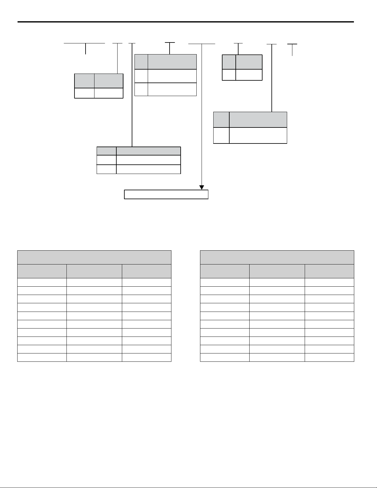
Nameplate
i.2 Receiving
A – Normal Duty amps / Heavy Duty
amps
B – Software version
C –
Address
<1>
D – Enclosure type
E – Serial number
Figure i.3 Nameplate Information Example
<1> The address of the head office of Yaskawa Electric Corporation (responsible for product liability) is shown on the nameplate.
YASKAWA ELECTRIC TOEP C710636 04C U1000 Industrial MATRIX Drive Quick Start Guide
F – Lot number
G – Output specifications
H – Input specifications
I – AC drive model
Refer to Figure i.4 for details.
13
Page 14
CIMR-U U 4 A A
0096
U A
U1000
Series
No.
Enclosure
Type
Design
Revision
Order
No.
Region
Code
U USA
IP00
A
No. Voltage Class
No.
Environmental
Specification
3-phase, 380-480 Vac
3-phase, 200-240 Vac
2
4
<1>
U
Humidity and dust
resistant
No.
Customized
Specifications
A
Without EMC
Noise Filter
Built-in EMC
Noise Filter
E
Refer to the tables below
i.2 Receiving
Figure i.4 Drive Model Number Definition
<1> Drives with these specifications do not guarantee complete protection for the environmental conditions indicated.
Three-Phase 200 V Class
n
Table i.1 Model Number and Specifications (200 V Class)
Normal Duty (ND)
C6-01 = 1
Drive Model
2o0028
2o0042
2o0054
2o0068
2o0081
2o0104
2o0130
2o0154
2o0192
2o0248
Reference Motor
Capacity kW (HP)
7.5 (10) 28
11 (15) 42
15 (20) 54
18.5 (25) 68
22 (30) 81
30 (40) 104
37 (50) 130
45 (60) 154
55 (75) 192
75 (100) 248
Rated Output
Current A
Drive Model
2o0028
2o0042
2o0054
2o0068
2o0081
2o0104
2o0130
2o0154
2o0192
2o0248
Heavy Duty (HD)
C6-01 = 0
Reference Motor
Capacity kW (HP)
5.5 (7.5) 22
7.5 (10) 28
11 (15) 42
15 (20) 54
18.5 (25) 68
22 (30) 81
30 (40) 104
37 (50) 130
45 (60) 154
55 (75) 192
Rated Output
Current A
14
YASKAWA ELECTRIC TOEP C710636 04C U1000 Industrial MATRIX Drive Quick Start Guide
Page 15

Three-Phase 400 V Class
n
Normal Duty (ND)
C6-01 = 1
Drive Model
4o0011
4o0014
4o0021
4o0027
4o0034
4o0040
4o0052
4o0065
4o0077
4o0096
4o0124
4o0156
4o0180
4o0216
4o0240
4o0302
4o0361
4o0414
Reference Motor
Capacity kW (HP)
5.5 (7.5) 11
7.5 (10) 14
11 (15) 21
15 (20) 27
18.5 (25) 34
22 (30) 40
30 (40) 52
37 (50) 65
45 (60) 77
55 (75) 96
75 (100) 124
90 (125) 156
110 (150) 180
132 (175) 216
150 (200) 240
185 (250) 302
220 (300) 361
260 (350) 414
Table i.2 Model Number and Specifications (400 V Class)
Rated Output
Current A
Drive Model
4o0011
4o0014
4o0021
4o0027
4o0034
4o0040
4o0052
4o0065
4o0077
4o0096
4o0124
4o0156
4o0180
4o0216
4o0240
4o0302
4o0361
4o0414
Capacity kW (HP)
Heavy Duty (HD)
C6-01 = 0
Reference Motor
3.7 (5) 9.6
5.5 (7.5) 11
7.5 (10) 14
11 (15) 21
15 (20) 27
18.5 (25) 34
22 (30) 40
30 (40) 52
37 (50) 65
45 (60) 77
55 (75) 96
75 (100) 124
90 (125) 156
110 (150) 180
132 (175) 216
150 (200) 240
185 (250) 302
220 (300) 361
i.2 Receiving
Rated Output
Current A
YASKAWA ELECTRIC TOEP C710636 04C U1000 Industrial MATRIX Drive Quick Start Guide
15
Page 16

i.3 Mechanical Installation
i.3 Mechanical Installation
This section outlines specifications, procedures, and the environment for proper mechanical installation of the drive.
u
Installation Environment
Install the drive in an environment matching the specifications in Table i.3 to help prolong the optimum performance life of
the drive.
Table i.3 Installation Environment
Environment Conditions
Installation Area Indoors
IP00/Open Type enclosure: -10 °C to +50 °C (14 °F to 122 °F)
IP20/NEMA Type 1 enclosure: -10 °C to +40 °C (14 °F to 104 °F)
Ambient Temperature
Humidity 95% RH or less and free of condensation
Storage Temperature -20 °C to +60 °C (-4 °F to +104 °F)
Surrounding Area
Altitude 1000 m (3281 ft.) or lower, up to 3000 m (9843 ft.) with derating
Vibration
Orientation Install the drive vertically to maintain maximum cooling effects.
Drive reliability improves in environments without wide temperature fluctuations.
When using the drive in an enclosure panel, install a cooling fan or air conditioner in the area to ensure that the air
temperature inside the enclosure does not exceed the specified levels.
Do not allow ice to develop on the drive.
Install the drive in an area free from:
• oil mist and dust
• metal shavings, oil, water, or other foreign materials
• radioactive materials
• combustible materials (e.g., wood)
• harmful gases and liquids
• excessive vibration
• chlorides
• direct sunlight.
10 to 20 Hz at 9.8 m/s2 (32.15 ft/s2)
20 to 55 Hz at 5.9 m/s2 (19.36 ft/s2) (Models 2o0028 to 2o0081 and 4o0011 to 4o0077)
2.0 m/s2 (6.56 ft/s2) (Models 2o0104 to 2o0248 and 4o0096 to 4o0414)
NOTICE: Avoid placing drive peripheral devices, transformers, or other electronics near the drive as the noise created can lead to erroneous
operation. If such devices must be used in close proximity to the drive, take proper steps to shield the drive from noise.
NOTICE: Prevent foreign matter such as metal shavings and wire clippings from falling into the drive during installation. Failure to comply
could result in damage to the drive. Place a temporary cover over the top of the drive during installation. Remove the temporary cover before
drive start-up, as the cover will reduce ventilation and cause the drive to overheat.
u
Installation Orientation and Spacing
NOTICE: Install the drive upright as illustrated in Figure i.5. Failure to comply may damage the drive due to improper cooling.
Figure i.5 Correct Installation Orientation
NOTICE: Install the drive upright as specified in the manual. Failure to comply may damage the drive due to improper cooling.
Single Drive Installation
n
Figure i.6 shows the installation distance required to maintain sufficient space for airflow and wiring.
16
YASKAWA ELECTRIC TOEP C710636 04C U1000 Industrial MATRIX Drive Quick Start Guide
Page 17

A
C
A
B
B
D
E
Side Clearance Top/Bottom Clearance
B
A
D
C
i.3 Mechanical Installation
A – 50 mm (1.97 in) minimum
B – 30 mm (1.18 in) minimum
C – 200 mm (7.87 in) minimum
Figure i.6 Correct Installation Spacing
Note: IP20/NEMA Type 1 enclosure and IP00/Open Type enclosure models require the same amount of space above and below the drive for
u
Instructions on Installation Using the Eye Bolts and Hanging Brackets
installation.
D – 120 mm (4.72 in) minimum
E – Airflow direction
Eye bolts and hanging brackets are used to install the drive or to temporarily lift the drive during drive replacement. Using the
eye bolts and hanging brackets, the drive can be installed in an enclosure panel or on a wall. Do not leave the drive suspended
by the wires in a horizontal or vertical position for long periods of time. Do not transport the drive over long distances. Read
the following precautions and instructions before installing the drive.
WARNING! Crush Hazard. Observe the following instructions and precautions. Failure to comply could result in serious injury or death from
falling equipment.
Only use vertical suspension to temporarily lift the drive during installation to an enclosure panel. Do not use vertical suspension to transport
the drive.
Confirm that the spring washer is completely closed prior to lifting to prevent damage to the drive.
Use screws to securely affix the drive front cover, terminal blocks, and other drive components prior to vertical suspension.
Do not subject the drive to vibration or impact greater than 1.96 m/s2 (0.2 G) while it is suspended by the wires.
Do not leave the drive unattended while it is suspended by the wires.
Do not attempt to flip the drive over while it is suspended by the wires.
Horizontal Suspension of Drive Models 2o0154 to 2o0248 and 4o0156 to 4o0414
n
To make a wire hanger or frame for use when lifting the drive with a crane, lay the drive in a horizontal position and pass a
wire through the hanging brackets.
YASKAWA ELECTRIC TOEP C710636 04C U1000 Industrial MATRIX Drive Quick Start Guide
A – No space between drive and
washer
B – Spring washer fully closed
Figure i.7 Spring Washer
C – Space between drive and washer
D – Spring washer open
17
Page 18

2□0154A, 2□0192A, 2□0248,
4□0156A, 4□0180A, and 4□0216 to 4□0414
2□0154F, 2 □0192F, 4□0156F, and 4 □0180F
Suspending angle:
50° or greater
i.3 Mechanical Installation
NOTICE: Use the hanging brackets on the top and hanging holes of the bottom cover when lifting models 2o0154F, 2o0192F, 4o0156F,
and 4o0180F.
Figure i.8 Horizontal Suspension (Models 2o0154 to 2o0248 and 4o0156 to 4o0414)
Vertical Suspension of the Drive
n
Follow the procedure described below when suspending the drive with eye bolts or hanging brackets.
o
Models 2
WARNING! Crush Hazard. Use an adequate length of wire to ensure a 50° or wider suspension angle as illustrated in Figure i.9. The
maximum allowable load of the eye bolts cannot be guaranteed when the drive is suspended with the wires at angles less than 50°. Failure
to comply may result in serious injury or death from falling equipment.
0028 to 2o0130 and 4o0011 to 4o0124
1. Pass wire through the holes of the two eye bolts.
Figure i.9 Drive Suspension Using Wires and Eye Bolts
(Models 2o0028 to 2o0130 and 4o0011 to 4o0124)
2. Gradually take up the slack in the wires and hoist the drive after the wires are stretched tight.
3. Lower the drive when ready to install in the enclosure panel. Stop lowering the drive when it is near the floor, then slowly
begin lowering the drive again until the drive is placed correctly.
Models 2o0154 to 2o0248 and 4o0156 to 4o0414
18
YASKAWA ELECTRIC TOEP C710636 04C U1000 Industrial MATRIX Drive Quick Start Guide
Page 19
Suspending angle:
50° or greater
i.3 Mechanical Installation
WARNING! Crush Hazard. Use an adequate length of wire to ensure a 50° or wider suspension angle as illustrated in Figure i.10. The
maximum allowable load of the eye bolts cannot be guaranteed when the drive is suspended with the wires at angles less than 50°. Failure
to comply may result in serious injury or death from falling equipment.
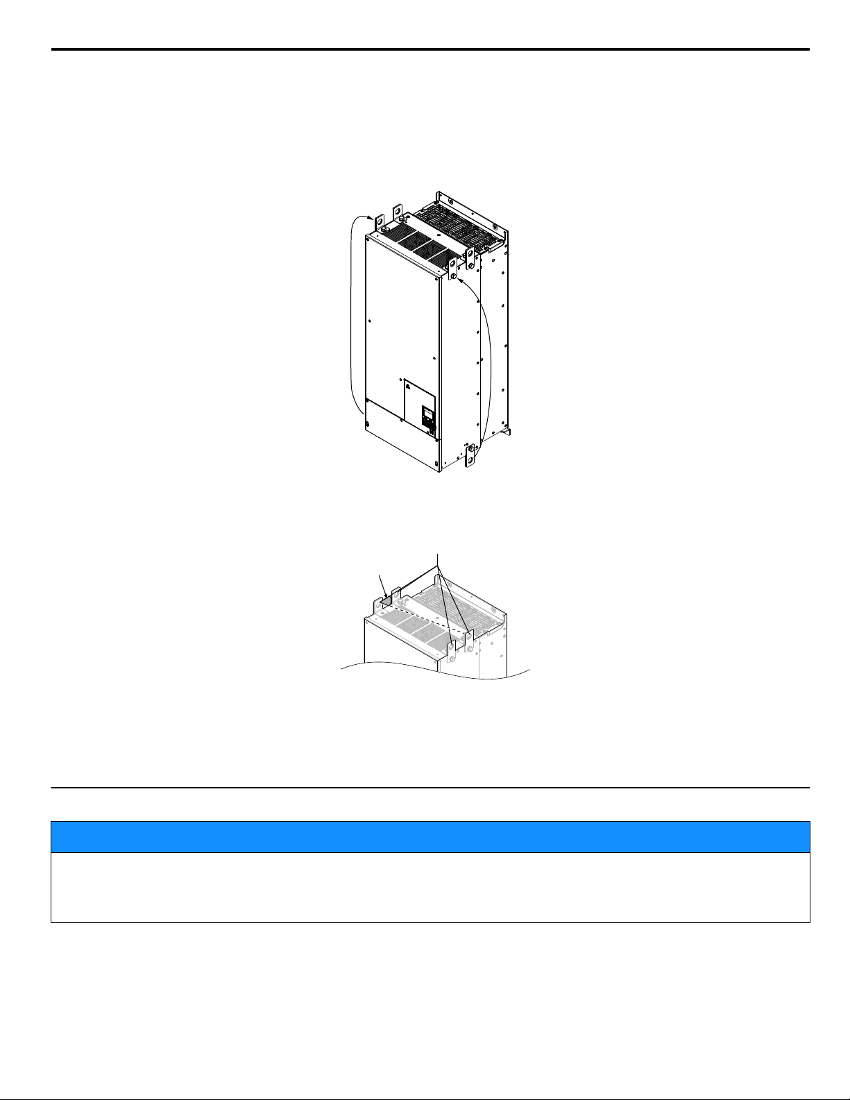
1. Remove the two hanging brackets from the drive lower side panels and bolt them on the top panel.
Note: 1. Tighten the hanging brackets with the specified tightening torque: M10: 18 to 23 N·m (159 to 204 in-lb),
M12: 32 to 40 N·m (283 to 354 in-lb).
2.
Four hanging brackets are attached to the top of NEMA Type 1 drives 2o0154F, 2o0192F, 4o0156F, and 4o0180F.
Figure i.10 Location of Hanging Brackets (Models 2o0154 to 2o0248 and 4o0156 to 4o0414)
2. Pass wire through the holes of all four hanging brackets.
Figure i.11 Drive Suspension Using Wires and Hanging Brackets (Models 2o0154 to 2o0248 and 4o0156 to 4o0414)
3. Gradually take up the slack in the wires and hoist the drive after the wires are stretched tight.
4. Lower the drive when ready to install in the enclosure panel. Stop lowering the drive when it is near the floor, then slowly
begin lowering the drive again until the drive is placed correctly.
u
Drive Dimensions
NOTICE
Refer to the U1000 Industrial MATRIX Drive Technical Manual SIEP C710636 04 for IP20/NEMA Type 1 and IP00/Open
Chassis dimensions.
The U1000 Industrial MATRIX Drive Technical Manual is posted on the Yaskawa website, www.yaskawa.com.
YASKAWA ELECTRIC TOEP C710636 04C U1000 Industrial MATRIX Drive Quick Start Guide
19
Page 20

i.4 Electrical Installation
i.4 Electrical Installation
u
Standard Connection Diagram
Connect the drive and peripheral devices as shown in Figure i.12. It is possible to set and run the drive via the digital operator
without connecting digital I/O wiring.
NOTICE: Inadequate wiring could result in damage to the drive. Install adequate branch circuit protection per applicable codes. The drive
is suitable for use on a circuit capable of delivering not more than 100,000 RMS symmetrical amperes, 240 Vac maximum (200 V class),
480 Vac maximum (400 V class: 4E
protected by branch circuit protection devices specified in this document.
NOTICE: Do not connect AC control circuit ground to drive enclosure. Improper drive grounding can cause control circuit malfunction.
NOTICE: Route motor leads U/T1, V/T2, and W/T3 separate from all other leads to reduce possible interference related issues. Failure to
comply may result in abnormal operation of drive and nearby equipment.
NOTICE: Correctly set Sink/Source jumper S3 for internal power supply. Failure to comply may result in damage to the drive.
Note: The minimum load for the relay outputs M1-M2, M3-M4, M5-M6, and MA-MB-MC is 10 mA.
oooo
and 4W
oooo
), and 500 Vac maximum (400 V class: 4A
oooo
and 4P
oooo
) when
20
YASKAWA ELECTRIC TOEP C710636 04C U1000 Industrial MATRIX Drive Quick Start Guide
Page 21

+
-
+
-
+
+
-
+
-
+
+
-
S1
S2
S3
S4
S5
S6
S7
MP
DM
DM
RP
A1
A2
A3
0 V
AC
R
R
S
S-
IG
H1
H2
HC
Drive
2 k
S8
SC
0 V
0 V
AC
FM
AM
AC
E (G)
S1
S2
<14>
<8>
<15>
<12>
<9>
<11>
<8>
<5>
<3>
+24 V
+V
MA
M1
M2
MB
MC
Forward Run / Stop
Reverse Run / Stop
External fault
Fault reset
Multi-speed step 1
Multi-speed step 2
External Baseblock
Jog speed
Multi-function
digtial inputs
(default setting)
Sink / Source mode
selection wire link
(default: Sink)
CN5-C
CN5-B
CN5-A
Option board
Pulse Train Input
(max 32 kHz)
Shield ground
terminal
Multi-function
analog/pulse
train inputs
Power supply +10.5 Vdc, max. 20 mA
Analog Input 1 (Frequency Reference Bias)
0 to +/-10Vdc (20 kΩ)
4 to 20 mA (250 Ω) / 0 to 20 mA (250 Ω)
Analog Input 2 (Frequency Reference Bias)
0 to +10Vdc (20 kΩ)
4 to 20 mA (250 Ω) / 0 to 20 mA (250 Ω)
Analog Input 3 (Aux. Frequency Reference)
0 to +/-10Vdc (20 kΩ)
4 to 20 mA (250 Ω) / 0 to 20 mA (250 Ω)
-V
Power supply, -10.5 Vdc, max. 20 mA
Safety
switch
MEMOBUS/Modbus comm.
RS-422/RS-485
max. 115.2 kbps
Safe Disable inputs
Wire
jumper
Open
Safety relay /
controller
Termination resistor
(120 , 1/2 W)
DIP
Switch S2
Fault relay output
250 Vac, max. 1 A
30 Vdc, max 1 A
(min. 5 Vdc, 10 mA)
Multi-function relay output (During Run)
250 Vac, max. 1 A
30 Vdc, max 1 A
(min. 5 Vdc, 10 mA)
Multi-function pulse train output
(Output frequency)
0 to 32 kHz (2.2 k )
Multi-function analog output 1
(Output frequency)
-10 to +10 Vdc (2mA)
or 4 to 20 mA
EDM (Safety Electronic Device Monitor)
Main Circuit
Control Circuit
shielded line
twisted-pair shielded line
main circuit terminal
control circuit terminal
R/L1
S/L2
T/L3
M3
M4
Multi-function relay output (Zero Speed)
250 Vac, max. 1 A
30 Vdc, max 1 A
(min. 5 Vdc, 10 mA)
M5
M6
Multi-function relay output (Speed Agree 1)
250 Vac, max. 1 A
30 Vdc, max 1 A
(min. 5 Vdc, 10 mA)
SP
SN
<10>
AMFM
V
I
V
I
DIP Switch S1
A2 Volt/Curr. Sel
DIP Switch S4
A3 Analog/PTC
Input Sel
PTC
AI
Off
On
DIP Switch S2
Term. Res. On/Off
Jumper S3
H1, H2
Sink/Source Sel.
Jumper S5
AM/FM Volt./Curr.
Selection
Terminal board
jumpers and switches
FM
+
-
AM
<6>
<13>
Ω
Ω
<12>
Multi-function analog output 2
(Output current)
-10 to +10 Vdc (2mA)
or 4 to 20 mA
Fuse
A+
A-
B-
Z-
B+
Z+
a+
ab+
bz+
z-
FE
IP
IG
TB1
SD
TB2
B track monitor
A track monitor
M
U/T1
V/T2
W/T
U
V
W
3
Ground
PG
PG- X3
connectors
(option)
Ω
Slide Switch S6
DM+, DMN.C./N.O. Selection
N.C.
N.O.
<7>
p1
n1
Terminals p1, n1 are for connection
options. Never connect power supply
lines to these terminals.
<1>
<2>
<4>
Cooling fan
M
FU
FV
FW
GFCI (MCCB)
R
T
S
Three-phase
power supply
240 to 500 V
50/60 Hz
(Depending on
model capacity)
2MCCB
r1
s1
t1
MC
Wiring sequence should shut off
power to the drive when a fault
output is triggered.
ON
OFF
EMC filter
Switch
<16>
24
0
FE
24 V
0 V
24 V Power Supply
Terminals
<17>
YASKAWA ELECTRIC TOEP C710636 04C U1000 Industrial MATRIX Drive Quick Start Guide
Figure i.12 Drive Standard Connection Diagram (example: model 2o0028)
i.4 Electrical Installation
21
Page 22

i.4 Electrical Installation
<1> When setting L5-02 to 1 to trigger a fault output whenever the fault restart function is activated, a sequence to interrupt power when a fault occurs
will turn off power to the drive as the drive attempts to restart. The default setting for L5-02 is 0 (Fault output not active during restart attempt).
<2> Self-cooling motors do not require wiring that is necessary for motors using a cooling fan.
<3> Supplying power to the control circuit separately from the main circuit requires 24 V power supply (option).
<4> PG option card wiring is not necessary for control modes that do not use a motor speed feedback signal.
<5> This figure illustrates an example of a sequence input to S1 through S8 using a non-powered relay or an NPN transistor. Install the wire link between
terminals SC-SP for Sink mode, between SC-SN for Source mode, or leave the link out for external power supply. Never short terminals SP and
SN, as it will damage the drive.
<6> This voltage source supplies a maximum current of 150 mA when not using a digital input card DI-A3.
<7> Wire the fault relay output separately from the main circuit power supply and other power lines.
<8> The maximum output current capacity for the +V and -V terminals on the control circuit is 20 mA. Never short terminals +V, -V, and AC, as it can
cause erroneous operation or damage the drive.
<9> Set DIP switch S1 to select between a voltage or current input signal to terminal A2. The default setting is for current input.
<10> Set DIP switch S4 to select between analog or PTC input for terminal A3.
<11> Set DIP switch S2 to the ON position to enable the termination resistor in the last drive in a MEMOBUS/Modbus network.
<12> Monitor outputs work with devices such as analog frequency meters, ammeters, voltmeters, and wattmeters. They are not intended for use as a
feedback-type signal.
<13> Use jumper S5 to select between voltage or current output signals at terminals AM and FM. Set parameters H4-07 and H4-08 accordingly.
<14> Use jumper S3 to select between Sink mode, Source mode, and external power supply for the Safe Disable inputs.
<15> Disconnect the wire jumper between H1 - HC and H2 - HC when utilizing the Safe Disable input.
<16>
Models UUoAoooo and UUoPoooo do not have a built-in EMC filter switch.
<17>
Models UUoPoooo and UUoWoooo have terminals 24, 0, and FE.
WARNING! Sudden Movement Hazard. Do not close the wiring for the control circuit unless the multifunction input terminal parameters are
properly set. Improper sequencing of run/stop circuitry could result in death or serious injury from moving equipment.
WARNING! Sudden Movement Hazard. Ensure start/stop and safety circuits are wired properly and in the correct state before energizing
the drive. Failure to comply could result in death or serious injury from moving equipment. When programmed for 3-Wire control, a momentary
closure on terminal S1 may cause the drive to start.
WARNING! Sudden Movement Hazard. When using a 3-Wire sequence, set the drive to 3-Wire sequence prior to wiring the control terminals
and set parameter b1-17 to 0 so the drive will not accept a Run command at power up (default). If the drive is wired for a 3-Wire sequence
but set up for a 2-Wire sequence (default), and parameter b1-17 is set to 1 so the drive accepts a Run command at power up, the motor
will rotate in reverse direction at drive power up and may cause injury.
WARNING! Sudden Movement Hazard. Confirm the drive I/O signals and external sequence before executing the application preset
function. Executing the application preset function or setting A1-06 ≠ 0 will change the drive I/O terminal functions and may cause unexpected
equipment operation. Failure to comply may cause death or serious injury.
NOTICE: When using the automatic fault restart function with wiring designed to shut off the power supply upon drive fault, make sure the
drive does not trigger a fault output during fault restart (L5-02 = 0, default). Failure to comply will prevent the automatic fault restart function
from working properly.
22
YASKAWA ELECTRIC TOEP C710636 04C U1000 Industrial MATRIX Drive Quick Start Guide
Page 23

Input filter
R/L1
S/L2
T/L3
U/T1
V/T2
W/T3
Control
board
Bidirectional IGBT
Control power supply
p1
n1
i.4 Electrical Installation
u
Main Circuit Connection Diagram
Refer to Figure i.13 when wiring the main circuit of the drive. Connections may vary based on drive capacity. The DC power
supply for the main circuit also provides power to the control circuit.
Figure i.13 Connecting Main Circuit Terminals
u
Main Circuit Wiring
This section describes the functions, specifications, and procedures required to safely and properly wire the main circuit in
the drive.
NOTICE: Do not solder the ends of wire connections to the drive. Soldered wiring connections can loosen over time. Improper wiring practices
could result in drive malfunction due to loose terminal connections.
NOTICE: Do not switch the drive input to start or stop the motor. Frequently switching the drive on and off shortens the lifetime of the DC
bus charge circuit and the DC bus capacitors, and can cause premature drive failures. For the full performance life, refrain from switching
the drive on and off more than once every 30 minutes.
u
Main Circuit Terminal Functions
Table i.4 Main Circuit Terminal Functions
Drive Model
Terminal Type
R/L1
T/L3
U/T1
W/T3
p1, n1 Momentary power loss recovery unit input
2o0028 to 2o0248 4o0011 to 4o0414
Main circuit power supply input Connects line power to the drive 21S/L2
Drive output Connects to the motor 21V/T2
100 Ω or less 10 Ω or less Grounding terminal 29
Function Page
Available for connecting a momentary power
loss recovery unit option
–
u
Protecting Main Circuit Terminals
Insulation Caps or Sleeves
n
Use insulation caps or sleeves when wiring the drive with crimp terminals. Take particular care to ensure that the wiring does
not touch nearby terminals or the surrounding case.
YASKAWA ELECTRIC TOEP C710636 04C U1000 Industrial MATRIX Drive Quick Start Guide
23
Page 24

Main circuit terminal
Terminals p1, n1
i.4 Electrical Installation
Main Circuit Protective Cover
n
Close the protective cover after wiring the main circuit terminals on 2o0028 to 2o0081 and 4o0011 to 4o0077.
Figure i.14 Main Circuit Protective Cover (Models 2o0028 to 2o0081 and 4o0011 to 4o0077)
Attach the protective covers after wiring the main circuit terminals and p1, and n1 terminals on models 2o0104 to 2o0248
and 4o0096 to 4o0414.
Figure i.15 Protective Cover (Models 2o0104 to 2o0248 and 4o0096 to 4o0414)
u
Main Circuit Wire Gauges and Tightening Torque
Use the tables in this section to select the appropriate wires and crimp terminals.
Gauges listed in the tables are for use in the United States.
Note: Wire gauge recommendations based on drive continuous current ratings (ND) using 75 °C 600 Vac vinyl-sheathed wire assuming ambient
temperature within 40 °C and wiring distance less than 100 m.
Consider the amount of voltage drop when selecting wire gauges. Increase the wire gauge when the voltage drop is greater
than 2% of motor rated voltage. Ensure the wire gauge is suitable for the terminal block. Use the following formula to calculate
the amount of voltage drop:
Line drop voltage (V) =
3 × wire resistance (Ω/km) × wire length (m) × current (A) × 10
-3
Refer to UL Standards Compliance on page 82 for information on UL compliance.
The wire gauges listed in the following tables are Yaskawa recommendations. Refer to local codes for proper wire gauge
selections.
24
YASKAWA ELECTRIC TOEP C710636 04C U1000 Industrial MATRIX Drive Quick Start Guide
Page 25

Three-Phase 200 V Class
n
Table i.5 Wire Gauge and Torque Specifications (Three-Phase 200 V Class)
Drive
Model
Terminal
R/L1, S/L2, T/L3
U/T1, V/T2, W/T3
2o0028
p1, n1
R/L1, S/L2, T/L3
U/T1, V/T2, W/T3
2o0042
p1, n1
R/L1, S/L2, T/L3
U/T1, V/T2, W/T3
2o0054
p1, n1
R/L1, S/L2, T/L3
U/T1, V/T2, W/T3
2o0068
p1, n1
R/L1, S/L2, T/L3
U/T1, V/T2, W/T3
2o0081
p1, n1
R/L1, S/L2, T/L3
U/T1, V/T2, W/T3
2o0104
p1, n1
For USA and Canada For South America
Recomm. Gauge
mm
2
(AWG, kcmil)
10
(8)
10
(8)
10
(8)
2.5
(14)
16
(6)
16
(6)
10
(8)
2.5
(14)
25
(4)
25
(4)
16
(6)
2.5
(14)
25
(4)
25
(4)
16
(6)
2.5
(14)
16 × 2
(6 × 2P)
16 × 2
(6 × 2P)
16
(6)
2.5
(14)
35
(1)
35
(1)
25
(4)
2.5
(14)
Wire Range
mm
2
(AWG, kcmil)
6 to 10
(10 to 8)
6 to 10
(10 to 8)
6 to 16
(10 to 6)
2.5 to 4
(14 to 12)
10 to 25
(8 to 3)
10 to 25
(8 to 3)
6 to 25
(10 to 3)
2.5 to 4
(14 to 12)
16 to 25
(6 to 3)
16 to 25
(6 to 3)
10 to 25
(8 to 3)
2.5 to 4
(14 to 12)
25
(4 to 3)
25
(4 to 3)
16 to 25
(6 to 3)
2.5 to 4
(14 to 12)
16 to 25 × 2
(6 to 3 × 2P)
16 to 25 × 2
(6 to 3 × 2P)
16 to 25
(6 to 3)
2.5 to 4
(14 to 12)
16 to 50 × 2
(6 to 1/0 × 2P)
16 to 50 × 2
(6 to 1/0 × 2P)
25 to 35
(4 to 1)
2.5 to 4
(14 to 12)
Recomm. Gauge
mm
2
(AWG, kcmil)
4
(12)
4
(12)
6
(10)
2.5
(14)
10
(8)
10
(8)
10
(8)
2.5
(14)
16
(5)
16
(5)
10
(8)
2.5
(14)
16
(5)
16
(5)
16
(5)
2.5
(14)
25
(3)
25
(3)
16
(5)
2.5
(14)
35
(1)
35
(1)
25
(3)
2.5
(14)
i.4 Electrical Installation
Wire Range
(AWG, kcmil)
10 to 50 × 2P
(8 to 1/0 × 2P)
10 to 50 × 2P
(8 to 1/0 × 2P)
2
mm
2.5 to 10
(14 to 8)
2.5 to 10
(14 to 8)
6 to 16
(10 to 5)
2.5 to 4
(14 to 12)
6 to 25
(10 to 3)
6 to 25
(10 to 3)
6 to 25
(10 to 3)
2.5 to 4
(14 to 12)
10 to 25
(8 to 3)
10 to 25
(8 to 3)
10 to 25
(8 to 3)
2.5 to 4
(14 to 12)
16 to 25
(5 to 3)
16 to 25
(5 to 3)
16 to 25
(5 to 3)
2.5 to 4
(14 to 12)
16 to 25
(5 to 3 × 2P)
16 to 25
(5 to 3 × 2P)
16 to 25
(5 to 3)
2.5 to 4
(14 to 12)
10 to 35
(8 to 1)
2.5 to 4
(14 to 12)
Screw
Size
M5
M5
M6
M4
M6
M6
M8
M4
M6
M6
M8
M4
M6
M6
M8
M4
M6
M6
M8
M4
M8
M8
M8
M4
Tightening
Torque
N·m (lb.in.)
2.3 to 2.7
(20.4 to 23.9)
3.9 to 4.9
(34.7 to 43.4)
1 to 1.4
(8.9 to 12.4)
4 to 6
(35.4 to 53.1)
8.8 to 10.8
(78.1 to 95.5)
1 to 1.4
(8.9 to 12.4)
4 to 6
(35.4 to 53.1)
8.8 to 10.8
(78.1 to 95.5)
1 to 1.4
(8.9 to 12.4)
4 to 6
(35.4 to 53.1)
8.8 to 10.8
(78.1 to 95.5)
1 to 1.4
(8.9 to 12.4)
4 to 6
(35.4 to 53.1)
8.8 to 10.8
(78.1 to 95.5)
1 to 1.4
(8.9 to 12.4)
8 to 10
(70.8 to 88.5)
8.8 to 10.8
(78.1 to 95.5)
1.2 to 2.0
(10.6 to 17.7)
YASKAWA ELECTRIC TOEP C710636 04C U1000 Industrial MATRIX Drive Quick Start Guide
25
Page 26

i.4 Electrical Installation
Drive
Model
2o0130
2o0154
2o0192
2o0248
Terminal
R/L1, S/L2, T/L3
U/T1, V/T2, W/T3
p1, n1
R/L1, S/L2, T/L3
U/T1, V/T2, W/T3
p1, n1
R/L1, S/L2, T/L3
U/T1, V/T2, W/T3
p1, n1
R/L1, S/L2, T/L3
U/T1, V/T2, W/T3
p1, n1
For USA and Canada For South America
Recomm. Gauge
mm
2
(AWG, kcmil)
25 × 2
(4 × 2P)
25 × 2
(4 × 2P)
25
(4)
2.5
(14)
25 × 2
(3 × 2P)
25 × 2
(3 × 2P)
25
(4)
2.5
(14)
35 × 2
(1 × 2P)
35 × 2
(1 × 2P)
25
(3)
2.5
(14)
70 × 2
(2/0 × 2P)
70 × 2
(2/0 × 2P)
25
(3)
2.5
(14)
Wire Range
mm
2
(AWG, kcmil)
16 to 50 × 2
(6 to 1/0 × 2P)
16 to 50 × 2
(6 to 1/0 × 2P)
25 to 35
(4 to 1)
2.5 to 4
(14 to 12)
25 to 95 × 2
(4 to 4/0 × 2P)
25 to 95 × 2
(4 to 4/0 × 2P)
25 to 70
(4 to 2/0)
2.5 to 4
(14 to 12)
25 to 95 × 2
(3 to 4/0 × 2P)
25 to 95 × 2
(3 to 4/0 × 2P)
25 to 70
(4 to 2/0)
2.5 to 4
(14 to 12)
35 to 95 × 2
(1 to 4/0 × 2P)
35 to 95 × 2
(1 to 4/0 × 2P)
25 to 95
(4 to 4/0)
2.5 to 4
(14 to 12)
Recomm. Gauge
mm
2
(AWG, kcmil)
16 × 2P
(5 × 2P)
16 × 2P
(5 × 2P)
16
(5)
2.5
(14)
25 × 2P
(3 × 2P)
25 × 2P
(3 × 2P)
25
(3)
2.5
(14)
35 × 2P
(1 × 2P)
35 × 2P
(1 × 2P)
25
(3)
2.5
(14)
50 × 2P
(1/0 × 2P)
50 × 2P
(1/0 × 2P)
35
(1)
2.5
(14)
Wire Range
mm
2
(AWG, kcmil)
10 to 50 × 2P
(8 to 1/0 × 2P)
10 to 50 × 2P
(8 to 1/0 × 2P)
16 to 35
(5 to 1)
2.5 to 4
(14 to 12)
16 to 95 × 2P
(5 to 4/0 × 2P)
16 to 95 × 2P
(5 to 4/0 × 2P)
25 to 70
(3 to 2/0)
2.5 to 4
(14 to 12)
25 to 95 × 2P
(3 to 4/0 × 2P)
25 to 95 × 2P
(3 to 4/0 × 2P)
25 to 70
(3 to 2/0)
2.5 to 4
(14 to 12)
35 to 95 × 2P
(1 to 4/0 × 2P)
35 to 95 × 2P
(1 to 4/0 × 2P)
25 to 95
(3 to 4/0)
2.5 to 4
(14 to 12)
Screw
Size
M8
M8
M8
M4
M10
M10
M10
M4
M10
M10
M10
M4
M10
M10
M12
M4
Tightening
Torque
N·m (lb.in.)
8 to 10
(70.8 to 88.5)
8.8 to 10.8
(78.1 to 95.5)
1.2 to 2.0
(10.6 to 17.7)
15 to 20
(133 to 177)
17.7 to 22.6
(156 to 200)
1.2 to 2.0
(10.6 to 17.7)
15 to 20
(133 to 177)
17.7 to 22.6
(156 to 200)
1.2 to 2.0
(10.6 to 17.7)
15 to 20
(133 to 177)
31.4 to 39.2
(278 to 347)
1.2 to 2.0
(10.6 to 17.7)
Three-Phase 400 V Class
n
Table i.6 Wire Gauge and Torque Specifications (Three-Phase 400 V Class)
Drive
Model
Terminal
R/L1, S/L2, T/L3
U/T1, V/T2, W/T3
4o0011
p1, n1
R/L1, S/L2, T/L3
U/T1, V/T2, W/T3
4o0014
p1, n1
For USA and Canada For South America
Recomm. Gauge
mm
2
(AWG, kcmil)
2.5
(14)
2.5
(14)
6
(10)
2.5
(14)
4
(12)
4
(12)
6
(10)
2.5
(14)
Wire Range
mm
2
(AWG, kcmil)
2.5 to 10
(14 to 8)
2.5 to 10
(14 to 8)
4 to 16
(12 to 6)
2.5 to 4
(14 to 12)
2.5 to 10
(14 to 8)
2.5 to 10
(14 to 8)
4 to 16
(12 to 6)
2.5 to 4
(14 to 12)
Recomm. Gauge
mm
2
(AWG, kcmil)
2.5
(14)
2.5
(14)
2.5
(14)
2.5
(14)
2.5
(14)
2.5
(14)
2.5
(14)
2.5
(14)
Wire Range
mm
2
(AWG, kcmil)
2.5 to 10
(14 to 8)
2.5 to 10
(14 to 8)
2.5 to 16
(14 to 5)
2.5 to 4
(14 to 12)
2.5 to 10
(14 to 8)
2.5 to 10
(14 to 8)
2.5 to 16
(14 to 5)
2.5 to 4
(14 to 12)
Screw
Size
M5
M5
M6
M4
M5
M5
M6
M4
Tightening
Torque
N·m (lb.in.)
2.3 to 2.7
(20.4 to 23.9)
3.9 to 4.9
(34.7 to 43.4)
1 to 1.4
(8.9 to 12.4)
2.3 to 2.7
(20.4 to 23.9)
3.9 to 4.9
(34.7 to 43.4)
1 to 1.4
(8.9 to 12.4)
26
YASKAWA ELECTRIC TOEP C710636 04C U1000 Industrial MATRIX Drive Quick Start Guide
Page 27

i.4 Electrical Installation
Drive
Model
4o0021
4o0027
4o0034
4o0040
4o0052
4o0065
4o0077
Terminal
R/L1, S/L2, T/L3
U/T1, V/T2, W/T3
p1, n1
R/L1, S/L2, T/L3
U/T1, V/T2, W/T3
p1, n1
R/L1, S/L2, T/L3
U/T1, V/T2, W/T3
p1, n1
R/L1, S/L2, T/L3
U/T1, V/T2, W/T3
p1, n1
R/L1, S/L2, T/L3
U/T1, V/T2, W/T3
p1, n1
R/L1, S/L2, T/L3
U/T1, V/T2, W/T3
p1, n1
R/L1, S/L2, T/L3
U/T1, V/T2, W/T3
p1, n1
For USA and Canada For South America
Recomm. Gauge
mm
2
(AWG, kcmil)
6
(10)
6
(10)
6
(10)
2.5
(14)
10
(8)
10
(8)
10
(8)
2.5
(14)
10
(8)
10
(8)
10
(8)
2.5
(14)
10
(8)
10
(8)
10
(8)
2.5
(14)
16
(6)
16
(6)
16
(6)
2.5
(14)
25
(4)
25
(4)
16
(6)
2.5
(14)
25
(3)
25
(3)
16
(6)
2.5
(14)
Wire Range
mm
2
(AWG, kcmil)
4 to 10
(12 to 8)
4 to 10
(12 to 8)
4 to 16
(12 to 6)
2.5 to 4
(14 to 12)
6 to 10
(10 to 8)
6 to 10
(10 to 8)
4 to 16
(12 to 6)
2.5 to 4
(14 to 12)
10
(8)
10
(8)
6 to 16
(10 to 6)
2.5 to 4
(14 to 12)
10 to 25
(8 to 3)
10 to 25
(8 to 3)
10 to 25
(10 to 3)
2.5 to 4
(14 to 12)
10 to 25
(8 to 3)
10 to 25
(8 to 3)
10 to 25
(8 to 3)
2.5 to 4
(14 to 12)
16 to 25
(6 to 3)
16 to 25
(6 to 3)
16 to 25
(6 to 3)
2.5 to 4
(14 to 12)
25
(4 to 3)
25
(4 to 3)
16 to 25
(6 to 3)
2.5 to 4
(14 to 12)
Recomm. Gauge
mm
2
(AWG, kcmil)
2.5
(14)
2.5
(14)
2.5
(14)
2.5
(14)
4
(12)
4
(12)
4
(12)
2.5
(14)
6
(10)
6
(10)
6
(10)
2.5
(14)
10
(8)
10
(8)
10
(8)
2.5
(14)
10
(8)
10
(8)
10
(8)
2.5
(14)
16
(5)
16
(5)
16
(5)
2.5
(14)
25
(3)
25
(3)
16
(5)
2.5
(14)
Wire Range
mm
2
(AWG, kcmil)
2.5 to 10
(14 to 8)
2.5 to 10
(14 to 8)
2.5 to 16
(14 to 5)
2.5 to 4
(14 to 12)
2.5 to 10
(14 to 8)
2.5 to 10
(14 to 8)
4 to 16
(12 to 5)
2.5 to 4
(14 to 12)
4 to 10
(12 to 8)
4 to 10
(12 to 8)
6 to 16
(10 to 5)
2.5 to 4
(14 to 12)
6 to 25
(10 to 3)
6 to 25
(10 to 3)
6 to 25
(10 to 3)
2.5 to 4
(14 to 12)
10 to 25
(8 to 3)
10 to 25
(8 to 3)
10 to 25
(8 to 3)
2.5 to 4
(14 to 12)
10 to 25
(8 to 3)
10 to 25
(8 to 3)
16 to 25
(5 to 3)
2.5 to 4
(14 to 12)
16 to 25
(5 to 3)
16 to 25
(5 to 3)
16 to 25
(5 to 3)
2.5 to 4
(14 to 12)
Screw
Size
M5
M5
M6
M4
M5
M5
M6
M4
M5
M5
M6
M4
M6
M6
M8
M4
M6
M6
M8
M4
M6
M6
M8
M4
M6
M6
M8
M4
Tightening
Torque
N·m (lb.in.)
2.3 to 2.7
(20.4 to 23.9)
3.9 to 4.9
(34.7 to 43.4)
1 to 1.4
(8.9 to 12.4)
2.3 to 2.7
(20.4 to 23.9)
3.9 to 4.9
(34.7 to 43.4)
1 to 1.4
(8.9 to 12.4)
2.3 to 2.7
(20.4 to 23.9)
3.9 to 4.9
(34.7 to 43.4)
1 to 1.4
(8.9 to 12.4)
4 to 6
(35.4 to 53.1)
8.8 to 10.8
(78.1 to 95.5)
1 to 1.4
(8.9 to 12.4)
4 to 6
(35.4 to 53.1)
8.8 to 10.8
(78.1 to 95.5)
1 to 1.4
(8.9 to 12.4)
4 to 6
(35.4 to 53.1)
8.8 to 10.8
(78.1 to 95.5)
1 to 1.4
(8.9 to 12.4)
4 to 6
(35.4 to 53.1)
8.8 to 10.8
(78.1 to 95.5)
1 to 1.4
(8.9 to 12.4)
YASKAWA ELECTRIC TOEP C710636 04C U1000 Industrial MATRIX Drive Quick Start Guide
27
Page 28

i.4 Electrical Installation
Drive
Model
4o0096
4o0124
4o0156
4o0180
4o0216
4o0240
4o0302
<1>
Terminal
R/L1, S/L2, T/L3
U/T1, V/T2, W/T3
p1, n1
R/L1, S/L2, T/L3
U/T1, V/T2, W/T3
p1, n1
R/L1, S/L2, T/L3
U/T1, V/T2, W/T3
p1, n1
R/L1, S/L2, T/L3
U/T1, V/T2, W/T3
p1, n1
R/L1, S/L2, T/L3
U/T1, V/T2, W/T3
p1, n1
R/L1, S/L2, T/L3
U/T1, V/T2, W/T3
p1, n1
R/L1, S/L2, T/L3
U/T1, V/T2, W/T3
p1, n1
For USA and Canada For South America
Recomm. Gauge
mm
2
(AWG, kcmil)
35
(1)
35
(1)
25
(4)
2.5
(14)
25 × 2
(4 × 2P)
25 × 2
(4 × 2P)
25
(4)
2.5
(14)
25 × 2
(3 × 2P)
25 × 2
(3 × 2P)
25
(4)
2.5
(14)
35 × 2
(2 × 2P)
35 × 2
(2 × 2P)
25
(3)
2.5
(14)
50 × 2
(1/0 × 2P)
50 × 2
(1/0 × 2P)
25
(3)
2.5
(14)
50 × 2
(1/0 × 2P)
50 × 2
(1/0 × 2P)
35
(2)
2.5
(14)
70 × 2
(3/0 × 2P)
70 × 2
(3/0 × 2P)
35
(1)
2.5
(14)
Wire Range
mm
2
(AWG, kcmil)
10 to 50
(8 to 1/0 × 2P)
10 to 50
(8 to 1/0 × 2P)
25 to 35
(4 to 1)
2.5 to 4
(14 to 12)
16 to 50 × 2
(6 to 1/0 × 2P)
16 to 50 × 2
(6 to 1/0 × 2P)
25 to 35
(4 to 1)
2.5 to 4
(14 to 12)
25 to 95 × 2
(4 to 4/0 × 2P)
25 to 95 × 2
(4 to 4/0 × 2P)
25 to 70
(4 to 2/0)
2.5 to 4
(14 to 12)
25 to 95 × 2
(3 to 4/0 × 2P)
25 to 95 × 2
(3 to 4/0 × 2P)
25 to 70
(4 to 2/0)
2.5 to 4
(14 to 12)
35 to 95 × 2
(2 to 4/0 × 2P)
35 to 95 × 2
(2 to 4/0 × 2P)
25 to 95
(4 to 4/0)
2.5 to 4
(14 to 12)
50 to 95 × 2
(1/0 to 4/0 × 2P)
50 to 95 × 2
(1/0 to 4/0 × 2P)
35 to 95
(2 to 4/0)
2.5 to 4
(14 to 12)
50 to 95 × 2
(1/0 to 4/0 × 2P)
50 to 95 × 2
(1/0 to 4/0 × 2P)
35 to 150
(1 to 300)
2.5 to 4
(14 to 12)
Recomm. Gauge
mm
2
(AWG, kcmil)
35
(1)
35
(1)
25
(3)
2.5
(14)
16 × 2P
(5 × 2P)
16 × 2P
(5 × 2P)
16
(5)
2.5
(14)
25 × 2P
(3 × 2P)
25 × 2P
(3 × 2P)
25
(3)
2.5
(14)
25 × 2P
(3 × 2P)
25 × 2P
(3 × 2P)
25
(3)
2.5
(14)
35 × 2P
(1 × 2P)
35 × 2P
(1 × 2P)
35
(1)
2.5
(14)
50 × 2P
(1/0 × 2P)
50 × 2P
(1/0 × 2P)
50
(1/0)
2.5
(14)
70 × 2P
(3/0 × 2P)
70 × 2P
(3/0 × 2P)
70
(3/0)
2.5
(14)
Wire Range
mm
2
(AWG, kcmil)
10 to 50 × 2P
(8 to 1/0 × 2P)
10 to 50 × 2P
(8 to 1/0 × 2P)
10 to 35
(8 to 1)
2.5 to 4
(14 to 12)
10 to 50 × 2P
(8 to 1/0 × 2P)
10 to 50 × 2P
(8 to 1/0 × 2P)
16 to 35
(5 to 1)
2.5 to 4
(14 to 12)
16 to 95 × 2P
(5 to 4/0 × 2P)
16 to 95 × 2P
(5 to 4/0 × 2P)
25 to 70
(3 to 2/0)
2.5 to 4
(14 to 12)
25 to 95 × 2P
(3 to 4/0 × 2P)
25 to 95 × 2P
(3 to 4/0 × 2P)
25 to 70
(3 to 2/0)
2.5 to 4
(14 to 12)
25 to 95 × 2P
(3 to 4/0 × 2P)
25 to 95 × 2P
(3 to 4/0 × 2P)
25 to 95
(3 to 4/0)
2.5 to 4
(14 to 12)
35 to 95 × 2P
(1 to 4/0 × 2P)
35 to 95 × 2P
(1 to 4/0 × 2P)
35 to 95
(1 to 4/0)
2.5 to 4
(14 to 12)
50 to 95 × 2P
(1/0 to 4/0 × 2P)
50 to 95 × 2P
(1/0 to 4/0 × 2P)
35 to 150
(1 to 300)
2.5 to 4
(14 to 12)
Screw
Size
M8
M8
M8
M4
M8
M8
M8
M4
M10
M10
M10
M4
M10
M10
M10
M4
M10
M10
M12
M4
M10
M10
M12
M4
M10
M10
M12
M4
Tightening
Torque
N·m (lb.in.)
8 to 10
(70.8 to 88.5)
8.8 to 10.8
(78.1 to 95.5)
1.2 to 2.0
(10.6 to 17.7)
8 to 10
(70.8 to 88.5)
8.8 to 10.8
(78.1 to 95.5)
1.2 to 2.0
(10.6 to 17.7)
15 to 20
(133 to 177)
17.7 to 22.6
(156 to 200)
1.2 to 2.0
(10.6 to 17.7)
15 to 20
(133 to 177)
17.7 to 22.6
(156 to 200)
1.2 to 2.0
(10.6 to 17.7)
15 to 20
(133 to 177)
31.4 to 39.2
(278 to 347)
1.2 to 2.0
(10.6 to 17.7)
15 to 20
(133 to 177)
31.4 to 39.2
(278 to 347)
1.2 to 2.0
(10.6 to 17.7)
15 to 20
(133 to 177)
31.4 to 39.2
(278 to 347)
1.2 to 2.0
(10.6 to 17.7)
28
YASKAWA ELECTRIC TOEP C710636 04C U1000 Industrial MATRIX Drive Quick Start Guide
Page 29
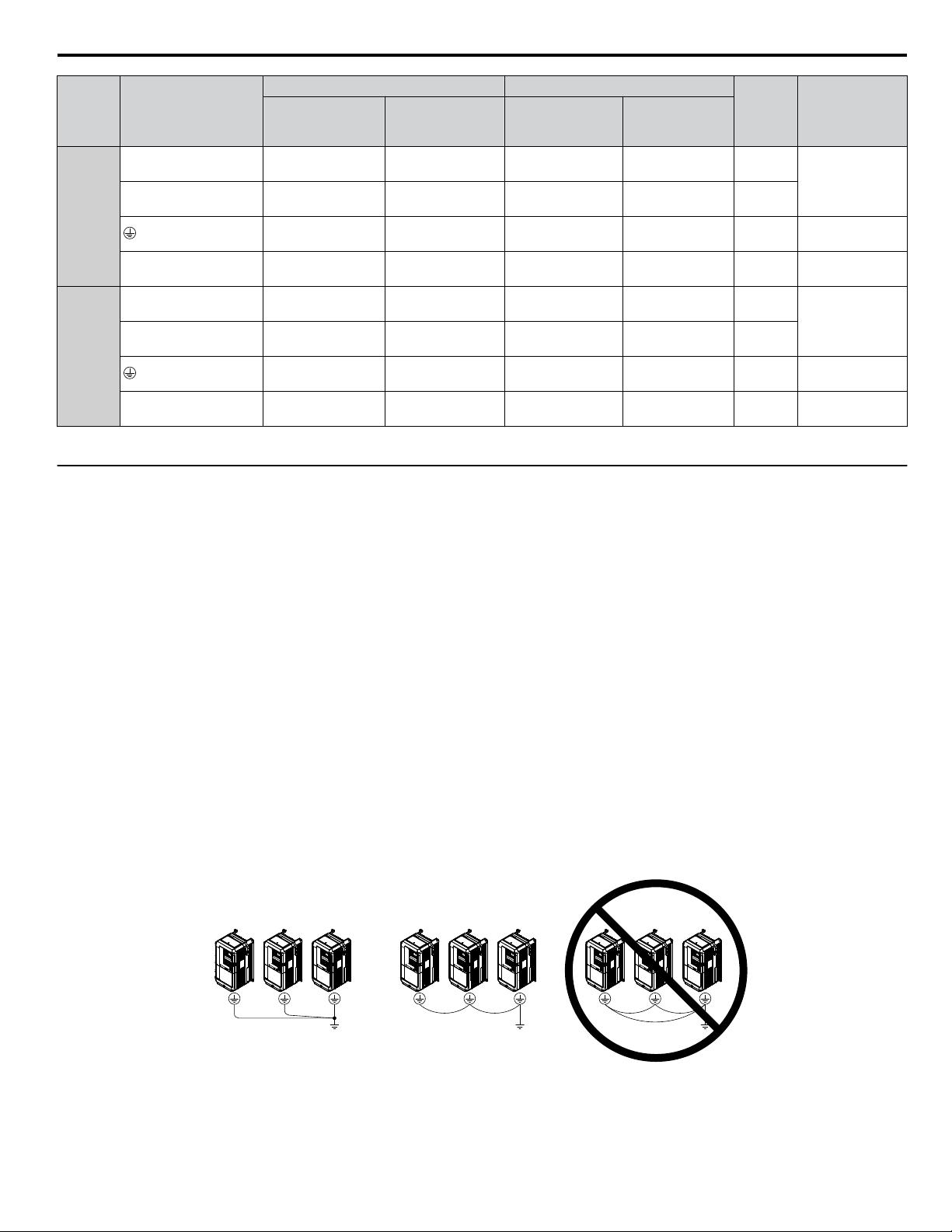
i.4 Electrical Installation
For USA and Canada For South America
Drive
Model
4o0361
<1>
4o0414
<1>
<1> Take additional measures in accordance with IEC/EN 61800-5-1 when wiring an EMC filter is installed. Refer to the Technical Manual for details.
u
Main Circuit Terminal and Motor Wiring
Terminal
R/L1, S/L2, T/L3
U/T1, V/T2, W/T3
p1, n1
R/L1, S/L2, T/L3
U/T1, V/T2, W/T3
p1, n1
Recomm. Gauge
(AWG, kcmil)
2
mm
95 × 2
(4/0 × 2P)
95 × 2
(4/0 × 2P)
50
(1/0)
2.5
(14)
150 × 2
(300 × 2P)
150 × 2
(300 × 2P)
50
(1/0)
2.5
(14)
Wire Range
(AWG, kcmil)
(3/0 to 4/0 × 2P)
(3/0 to 4/0 × 2P)
95 to 150 × 2
(4/0 to 300 × 2P)
95 to 150 × 2
(4/0 to 300 × 2P )
2
mm
70 to 95 × 2
70 to 95 × 2
50 to 150
(1/0 to 300)
2.5 to 4
(14 to 12)
50 to 240
(1/0 to 400)
2.5 to 4
(14 to 12)
Recomm. Gauge
(AWG, kcmil)
2
mm
95 × 2P
(4/0 × 2P)
95 × 2P
(4/0 × 2P)
95
(4/0)
2.5
(14)
95 × 2P
(4/0 × 2P)
95 × 2P
(4/0 × 2P)
95
(4/0)
2.5
(14)
Wire Range
(AWG, kcmil)
70 to 95 × 2P
(3/0 to 4/0 × 2P)
70 to 95 × 2P
(3/0 to 4/0 × 2P)
95 to 150 × 2P
(4/0 to 300 × 2P)
95 to 150 × 2P
(4/0 to 300 × 2P )
2
mm
70 to 150
(3/0 to 300)
2.5 to 4
(14 to 12)
70 to 240
(3/0 to 400)
2.5 to 4
(14 to 12)
Screw
Size
M10
M10
M12
M4
M12
M12
M12
M4
Tightening
Torque
N·m (lb.in.)
15 to 20
(133 to 177)
31.4 to 39.2
(278 to 347)
1.2 to 2.0
(10.6 to 17.7)
25 to 35
(221 to 310)
31.4 to 39.2
(278 to 347)
1.2 to 2.0
(10.6 to 17.7)
This section outlines the various steps, precautions, and checkpoints for wiring the main circuit terminals and motor terminals.
NOTICE: When connecting the motor to the drive output terminals U/T1, V/T2, and W/T3, the phase order for the drive and motor should
match. Failure to comply with proper wiring practices may cause the motor to run in reverse if the phase order is backward.
NOTICE: Route motor leads U/T1, V/T2, and W/T3 separate from all other leads to reduce possible interference related issues. Failure to
comply may result in abnormal operation of drive and nearby equipment.
Ground Wiring
n
Follow the precautions below when wiring the ground for one drive or a series of drives.
WARNING! Electrical Shock Hazard. Always use a ground wire that complies with technical standards on electrical equipment and minimize
the length of the ground wire. Improper equipment grounding may cause dangerous electrical potentials on equipment chassis, which could
result in death or serious injury.
WARNING! Electrical Shock Hazard. Be sure to ground the drive ground terminal (200 V class: ground to 100 Ω or less; 400 V class: ground
to 10 Ω or less). Improper equipment grounding could result in death or serious injury by contacting ungrounded electrical equipment.
NOTICE: Do not share the ground wire with other devices such as welding machines or large-current electrical equipment. Improper
equipment grounding could result in drive or equipment malfunction due to electrical interference.
NOTICE: When using more than one drive, ground multiple drives according to instructions. Improper equipment grounding could result in
abnormal operation of drive or equipment.
Refer to Figure i.16 when using multiple drives. Do not loop the ground wire.
Figure i.16 Multiple Drive Wiring
YASKAWA ELECTRIC TOEP C710636 04C U1000 Industrial MATRIX Drive Quick Start Guide
29
Page 30

i.4 Electrical Installation
u
Control Circuit Terminal Block Functions
Drive parameters determine which functions apply to the multi-function digital inputs (S1 to S8), multi-function digital outputs
(M1 to M6), multi-function analog inputs (A1 to A3), and multi-function analog monitor outputs (FM, AM). The default
setting is listed next to each terminal in Figure i.12 on page 21.
WARNING! Sudden Movement Hazard. Always check the operation and wiring of control circuits after being wired. Operating a drive with
untested control circuits could result in death or serious injury.
WARNING! Sudden Movement Hazard. Confirm the drive I/O signals and external sequence before starting test run. Setting parameter
A1-06 may change the I/O terminal function automatically from the factory setting. Failure to comply may result in death or serious injury.
Input Terminals
n
Table i.7 lists the input terminals on the drive. Text in parenthesis indicates the default setting for each multi-function input.
Table i.7 Control Circuit Input Terminals
Type No. Terminal Name (Function) Function (Signal Level) Default Setting
Multi-function input 1
S1
(Closed: Forward run, Open: Stop)
Multi-function input 2
S2
(Closed: Reverse run, Open: Stop)
Multi-function input 3
S3
(External fault, N.O.)
Multi-Function
Digital Inputs
Multi-function input 4
S4
(Fault reset)
Multi-function input 5
S5
(Multi-step speed reference 1)
Multi-function input 6
S6
(Multi-step speed reference 2)
Multi-function input 7
S7
(Jog reference)
Multi-function input 8
S8
(Baseblock command (N.O.))
SC Multi-function input common Multi-function input common
SP Digital input power supply +24 Vdc 24 Vdc power supply for digital inputs, 150 mA max (only when not using
• Photocoupler
• 24 Vdc, 8 mA
• Refer to Sinking/Sourcing Mode for Digital Inputs on page 34.
digital input option DI-A3)
Safe Disable
Inputs
SN Digital input power supply 0 V
H1 Safe Disable input 1 • 24 Vdc, 8 mA
H2 Safe Disable input 2
HC Safe Disable function common Safe disable function common
NOTICE: Do not jumper or short terminals SP and SN. Failure to
comply will damage the drive.
• One or both open: Output disabled
• Both closed: Normal operation
• Internal impedance: 3.3 kΩ
• Off time of at least 1 ms
• Disconnect the wire jumpers shorting terminals H1, H2, and HC to use
the Safe Disable inputs. Set the S3 jumper to select between sinking,
sourcing mode, and the power supply as explained on page 34.
30
YASKAWA ELECTRIC TOEP C710636 04C U1000 Industrial MATRIX Drive Quick Start Guide
Page 31

i.4 Electrical Installation
Type No. Terminal Name (Function) Function (Signal Level) Default Setting
• Input frequency range: 0 to 32 kHz
• Signal Duty Cycle: 30 to 70%
• High level: 3.5 to 13.2 Vdc, low level: 0.0 to 0.8 Vdc
• Input impedance: 3 kΩ
-10 to 10 Vdc, 0 to 10 Vdc (input impedance: 20 kΩ)
• -10 to 10 Vdc, 0 to 10 Vdc (input impedance: 20 kΩ)
• 4 to 20 mA, 0 to 20 mA (input impedance: 250 Ω)
• Voltage or current input must be selected by DIP switch S1 and H3-09.
• -10 to 10 Vdc, 0 to 10 Vdc (input impedance: 20 kΩ)
• Use DIP switch S4 on the terminal board to select between analog and
PTC input.
Analog Inputs /
Pulse Train
Input
E (G) Ground for shielded lines and option cards –
Output Terminals
n
Multi-function pulse train input
RP
(Frequency reference)
+V Power supply for analog inputs 10.5 Vdc (max allowable current 20 mA)
-V Power supply for analog inputs -10.5 Vdc (max allowable current 20 mA)
Multi-function analog input 1
A1
(Frequency reference bias)
Multi-function analog input 2
A2
(Frequency reference bias)
Multi-function analog input 3
A3
(Auxiliary frequency reference)/PTC Input
AC Frequency reference common 0 V
Table i.8 lists the output terminals on the drive. Text in parenthesis indicates the default setting for each multi-function output.
Table i.8 Control Circuit Output Terminals
Type No. Terminal Name (Function) Function (Signal Level) Default Setting
Fault Relay
Output
Multi-Function
Digital Output
<1>
Monitor Output
Safety Monitor
Output
External Power
Supply
<1> Refrain from assigning functions to digital relay outputs that involve frequent switching, as doing so may shorten relay performance life. Switching
life is estimated at 200,000 times (assumes 1 A, resistive load).
MA N.O. output (Fault)
MB N.C. output (Fault)
MC Fault output common
M1
Multi-function digital output (During run)
M2
M3
Multi-function digital output (Zero speed)
M4
M5
Multi-function digital output (Speed Agree 1)
M6
MP Pulse train output (Output frequency) 32 kHz (max)
FM Analog monitor output 1 (Output frequency)
AM Analog monitor output 2 (Output current)
AC Monitor common 0 V
DM+ Safety monitor output
DM- Safety monitor output
24V External power supply 24 V (Max. 150 mA)
30 Vdc, 10 mA to 1 A; 250 Vac, 10 mA to 1 A
Minimum load: 5 Vdc, 10 mA
30 Vdc, 10 mA to 1 A; 250 Vac, 10 mA to 1 A
Minimum load: 5 Vdc, 10 mA
-10 to +10 Vdc, 0 to +10 Vdc, or 4 to 20 mA
Outputs status of Safe Disable function. Closed when both Safe
Disable channels are closed. Up to +48 Vdc 50 mA
Serial Communication Terminals
n
Table i.9 Control Circuit Terminals: Serial Communications
Type No. Signal Name Function (Signal Level)
R+ Communications input (+)
MEMOBUS/Modbus
Communication
<1> Enable the termination resistor in the last drive in a MEMOBUS/Modbus network by setting DIP switch S2 to the ON position. Refer to the manual
section on Control I/O Connections for more information.
YASKAWA ELECTRIC TOEP C710636 04C U1000 Industrial MATRIX Drive Quick Start Guide
<1>
R- Communications input (-)
S+ Communications output (+)
S- Communications output (-)
IG Shield ground 0 V
MEMOBUS/Modbus communication: Use an
RS-422 or RS-485 cable to connect the drive.
RS-422/RS-485
MEMOBUS/Modbus
communication
protocol
115.2 kbps (max.)
31
Page 32

MA MB MC
M1 M2 M5
M3 M4 M6
E(G)
HC H1 H2 DM+DM- IG R+ R- S+ S-
S1 S2 S3 S4 S5 S6 S7 S8 SN SC SP
V+ AC V- A1 A2 A3 FM AM AC MP RP AC
i.4 Electrical Installation
u
Terminal Configuration
The control circuit terminals are arranged as shown in Figure i.17.
Figure i.17 Control Circuit Terminal Arrangement
Wire Size and Torque Specifications
n
Select appropriate wire type and gauges from Table i.10. For simpler and more reliable wiring, use crimp ferrules on the wire
ends.
Table i.10 Wire Gauges
Tightening
Terminal
S1-S8, SC, SN, SP
H1, H2, HC
RP, V+, V-, A1, A2, A3,
AC, 24 V
MA, MB, MC
M1-M6
MP, FM, AM, AC
DM+, DMR+, R-, S+, S-, IG
u
Wiring the Control Circuit Terminal
Screw
Size
M3
Torque
N•m
(lb. in)
0.5 to 0.6
(4.4 to 5.3)
Bare Wire Terminal Ferrule-Type Terminal
Recomm.
wire size
mm2 (AWG)
0.75 (18)
Applicable
wire size
mm2 (AWG)
Stranded wire:
0.2 to 1.0
(24 to 16)
Solid wire:
0.2 to 1.5
(24 to 16)
Recomm.
wire size
mm2 (AWG)
0.5 (20)
Applicable
wire size
mm2 (AWG)
0.25 to 0.5
(24 to 20)
Wire Type
Shielded wire,
etc.
This section describes the proper procedures and preparations for wiring the control terminals.
WARNING! Electrical Shock Hazard. Do not remove covers or touch the circuit boards while the power is on. Failure to comply could result
in death or serious injury.
NOTICE: Separate control circuit wiring from main circuit wiring (terminals R/L1, S/L2, T/L3, U/T1, V/T2, W/T3, p1, n1) and other high-power
lines. Improper wiring practices could result in drive malfunction due to electrical interference.
NOTICE: Separate wiring for digital output terminals MA, MB, MC, and M1 to M6 from wiring to other` control circuit lines. Improper wiring
practices could result in drive or equipment malfunction or nuisance trips.
NOTICE: Use a class 2 power supply when connecting to the control terminals. Improper application of peripheral devices could result in
drive performance degradation due to improper power supply. Refer to NEC Article 725 Class 1, Class 2, and Class 3 Remote-Control,
Signaling, and Power Limited Circuits for requirements concerning class 2 power supplies.
NOTICE: Insulate shields with tape or shrink tubing to prevent contact with other signal lines and equipment. Improper wiring practices could
result in drive or equipment malfunction due to short circuit.
NOTICE: Connect the shield of shielded cable to the appropriate ground terminal. Improper equipment grounding could result in drive or
equipment malfunction or nuisance trips.
32
YASKAWA ELECTRIC TOEP C710636 04C U1000 Industrial MATRIX Drive Quick Start Guide
Page 33

A
E
B
C
D
i.4 Electrical Installation
NOTICE: Do not tighten screws beyond the specified tightening torque. Failure to comply may result in erroneous operation, damage to the
terminal block, or cause a fire.
NOTICE: Use shielded twisted-pair cables as indicated to prevent operating faults. Improper wiring practices could result in drive or
equipment malfunction due to electrical interference.
Wire the control circuit only after terminals have been properly grounded and main circuit wiring is complete. Refer to
Terminal Board Wiring Guide on page 33 for details. Prepare the ends of the control circuit wiring as shown in Figure i.
20. Refer to Wire Gauges on page 32.
Connect control wires as shown in Figure i.18 and Figure i.19.
A
A – Loosen screw to insert wire.
B – Single wire or stranded wire
Figure i.18 Terminal Board Wiring Guide
B
Preparing wire
terminal ends
C
C – Avoid fraying wire strands when
stripping insulation from wire. Strip
length 5.5 mm.
D – Blade depth of 0.4 mm or less
Blade width of 2.5 mm or less
D
Figure i.19 Terminal Board Location Inside the Drive
When setting the frequency by analog reference from an external potentiometer, use shielded twisted-pair wires (preparing
wire ends as shown in Figure i.20) and connect the shield to the ground terminal of the drive.
A – Drive side
B – Insulation
C – Control device side
Figure i.20 Preparing the Ends of Shielded Cables
YASKAWA ELECTRIC TOEP C710636 04C U1000 Industrial MATRIX Drive Quick Start Guide
D – Shield sheath (insulate with tape)
E – Shield
33
Page 34

SC
S8
S7
24 Vdc
SP
SN
External
24 Vdc
i.4 Electrical Installation
NOTICE: The analog signal wiring between the drive and the operator station or peripheral equipment should not exceed 50 meters when
using an analog signal from a remote source to supply the frequency reference. Failure to comply could result in poor system performance.
u
Sinking/Sourcing Mode for Digital Inputs
Use the wire jumper between terminals SC and SP or SC and SN to select between Sink mode, Source mode or external power
supply for the digital inputs S1 to S8 as shown in Table i.11 (Default: Sink mode, internal power supply).
NOTICE: Do not short terminals SP and SN. Failure to comply will damage the drive.
Table i.11 Digital Input Sink/Source/External Power Supply Selection
Mode
Drive Internal Power Supply
(Terminals SN and SP)
S7
S8
External 24 Vdc Power Supply
Sinking Mode (NPN)
Sourcing Mode (PNP)
u
Sinking/Sourcing Mode Selection for Safe Disable Inputs
SN
SC
SP
S7
S8
SN
SC
SP
24 Vdc
24 Vdc
External
24 Vdc
S7
S8
SN
SC
24 Vdc
SP
Use jumper S3 on the terminal board to select between Sink mode, Source mode or external power supply for the Safe Disable
inputs H1 and H2 as shown in Table i.12 (Default: Source mode, internal power supply).
34
YASKAWA ELECTRIC TOEP C710636 04C U1000 Industrial MATRIX Drive Quick Start Guide
Page 35

i.4 Electrical Installation
Table i.12 Safe Disable Input Sink/Source/External Power Supply Selection
Mode Drive Internal Power Supply External 24 Vdc Power Supply
Sinking Mode
HC
H1
Jumper S3
24 Vdc
External
24 Vdc
HC
H1
Jumper S3
24 Vdc
Sourcing Mode
u
Using the Pulse Train Output
H2
HC
H1
H2
Jumper S3
24 Vdc
External
24 Vdc
H2
HC
H1
H2
Jumper S3
24 Vdc
The pulse train output terminal MP can supply power or be used with an external power supply.
NOTICE: Connect peripheral devices in accordance with the specifications. Failure to comply may cause unexpected drive operation, and
can damage the drive or connected circuits.
Using Power from the Pulse Output Terminal (Source Mode)
n
The high voltage level of the pulse output terminal depends on the load impedance.
Load Impedance RL (kΩ) Output Voltage VMP (V) (insulated)
1.5 kΩ 5 V
4 kΩ 8 V
10 kΩ 10 V
Note:
The load resistance needed in order to get a certain high level voltage VMP can be calculated by: RL = VMP• 2 / (12 – VMP)
MP
Load Impedance
R
L
MP
V
AC
Figure i.21 Pulse Output Connection Using Internal Voltage Supply
Using External Power Supply (Sink Mode)
n
The high voltage level of the pulse output signal depends on the external voltage applied. The voltage must be between 12
and 15 Vdc. The load resistance must be adjusted so that the current is lower than 16 mA.
External Power Supply (V) Load Impedance (kΩ)
12 to 15 Vdc ±10% 1.0 kΩ or higher
YASKAWA ELECTRIC TOEP C710636 04C U1000 Industrial MATRIX Drive Quick Start Guide
35
Page 36

i.4 Electrical Installation
External Power Supply
Load Impedance
MP
AC
Sink Current
Figure i.22 Pulse Output Connection Using External Voltage Supply
u
Terminal A2 Input Signal Selection
Terminal A2 can be used to input either a voltage or a current signal. Select the signal type using switch S1 as explained in
Table i.13. Set parameter H3-09 accordingly as shown in Table i.14.
Note: If terminals A1 and A2 are both set for frequency bias (H3-02 = 0 and H3-10 = 0), both input values will be combined to create the frequency
reference.
Table i.13 DIP Switch S1 Settings
Setting Description
V (left position) Voltage input (-10 to +10 V or 0 to 10 V)
I (right position) Current input (4 to 20 mA or 0 to 20 mA): default setting
Table i.14 Parameter H3-09 Details
No. Parameter Name Description
Setting
Range
Default
Setting
Selects the signal level for terminal A2.
0: 0 to 10 Vdc
H3-09 Terminal A2 signal level selection
1: -10 to 10 Vdc
0 to 3 2
2: 4 to 20 mA
3: 0 to 20 mA
u
Terminal A3 Analog/PTC Input Selection
Terminal A3 can be configured either as multi-function analog input or as PTC input for motor thermal overload protection.
Use switch S4 to select the input function as described in Table i.15.
Table i.15 DIP Switch S4 Settings
Setting Description
AI (lower position) (default) Analog input for the function selected in parameter H3-06
PTC (upper position) PTC input. Parameter H3-06 must be set to E (PTC input)
u
Terminal AM/FM Signal Selection
The signal type for terminals AM and FM can be set to either voltage or current output using jumper S5 on the terminal board
as explained in Table i.16. When changing the setting of jumper S5, parameters H4-07 and H4-08 must be set accordingly.
The default selection is voltage output for both terminals.
Table i.16 Jumper S5 Settings
Terminal Voltage Output Current Output
36
Terminal AM
Terminal FM
V
I
AMFM
V
I
AMFM
V
I
AMFM
V
I
AMFM
YASKAWA ELECTRIC TOEP C710636 04C U1000 Industrial MATRIX Drive Quick Start Guide
Page 37

i.4 Electrical Installation
Table i.17 Parameter H4-07 and H4-08 Details
No. Parameter Name Description
H4-07 Terminal AM signal level selection 0: 0 to 10 Vdc
H4-08 Terminal FM signal level selection
u
MEMOBUS/Modbus Termination
1: -10 to 10 Vdc
2: 4 to 20 mA
Setting
Range
0 to 2 0
Default
Setting
This drive is equipped with a built-in termination resistor for the RS-422/RS-485 communication port. DIP switch S2 enables
or disabled the termination resistor as shown in Table i.18. The OFF position is the default. The termination resistor should
be placed to the ON position when the drive is the last in a series of slave drives.
Table i.18 MEMOBUS/Modbus Switch Settings
S2 Position Description
ON Internal termination resistor ON
OFF Internal termination resistor OFF (default setting)
u
Terminal DM+ and DM- Output Signal Selection
Slide switch S6 selects N.C. or N.O. as the state of the DM+ and DM- terminals for EDM output.
Table i.19 EDM Switch Settings
S2 Position Description
N.O. Normally open
N.C. Normally closed (default setting)
Note: Refer to Safe Disable Input Function on page 88 for details on EDM.
u
Enable the Internal EMC Filter
DANGER! Electrical Shock Hazard. Do not touch SW screw while power is applied to the drive. Failure to comply will result in death or
serious injury.
WARNING! Electrical Shock Hazard. Connect the ground cable correctly. Failure to comply may result in death or serious injury.
NOTICE: When disabling the internal EMC filter, move the screws from ON to OFF and then tighten to the specified torque. Completely
removing the screws or tightening the screws to an incorrect torque may cause drive failure.
Note: For floating, impedance grounded, or asymmetrically grounded networks, disconnect the internal EMC filter by moving the SW screw to
the OFF position.
Table i.20 shows asymmetrical grounded networks. Asymmetrical networks require first moving the SW screw to disconnect
the internal ground connection. (Drives are shipped with the SW screw installed at the OFF position.)
Table i.20 Asymmetrical Grounded Network
L1
Grounded at the corner of the delta
L3
Grounded at the middle of the side
L2
L1
L2L3
Single-phase, grounded at the end point
YASKAWA ELECTRIC TOEP C710636 04C U1000 Industrial MATRIX Drive Quick Start Guide
L1
N
37
Page 38

L1
L2
L3
L1
L2
L3
ON
OFF
SW
A
B
E(G)
IG R+ R- S+ S-
S1 S2 S3 S4 S5 S6 S7 S8 SN SC SP
V+ AC A1 A2 A3 FM AM AC 24VRP AC
M1 M2 M3 M4
MD ME MF
MA MB MC
i.4 Electrical Installation
Three-phase variable transformer without solidly grounded neutral
If EMC is a concern and the network is grounded symmetrically, install the SW screw to the ON position. Installing the SW
screw enables the internal EMC filter (Drives are shipped with the SW screw installed at the OFF position).
L1
L3
Figure i.23 Symmetrical Grounded Network
A – SW (ON) B – Screw (OFF)
Figure i.24 EMC Filter Switch Location
(Models 2E0028, 2W0028, 4E0011 to 4E0034, and 4W0011 to 4W0034)
L2
38
YASKAWA ELECTRIC TOEP C710636 04C U1000 Industrial MATRIX Drive Quick Start Guide
Page 39

ON
OFF
SW
A
B
S1 S2 S3 S4 S5 S6 S7 S8 SN SC SP
V+ AC A1 A2 A3 FM AM AC 24VRP AC
MD ME MF
MA MB MC
ON
OFF
SW
A
B
i.4 Electrical Installation
A – SW (ON) B – Screw (OFF)
Figure i.25 EMC Filter Switch Location
(Models 2E0042, 2W0042, 2E0054, 2W0054, 4E0040 to 4E0077, and 4W0040 to 4W0077)
A – SW (ON)
B – Screw (OFF)
Figure i.26 EMC Filter Switch Location
(Models 2E0104, 2W0104, 2E0130, 2W0130, 4E0096, 4W0096, 4E0124, and 4W0124)
YASKAWA ELECTRIC TOEP C710636 04C U1000 Industrial MATRIX Drive Quick Start Guide
39
Page 40

A
B
B
A
B
A
i.4 Electrical Installation
A – SW (ON) B – Screw (OFF)
(Models 2E0154, 2W0154, 2E0192, 2W0192, 4E0156, 4W0156, 4E0180, and 4W0180)
Figure i.27 EMC Filter Switch Location
A – SW (ON)
B – Screw (OFF)
Figure i.28 EMC Filter Switch Location
(Models 2E0248, 2W0248, 4EU0216, 4W0216, 4E0240, and 4W0240)
40
YASKAWA ELECTRIC TOEP C710636 04C U1000 Industrial MATRIX Drive Quick Start Guide
Page 41

A
B
B
A
n1 p1
u
Wiring Checklist
i.4 Electrical Installation
A – SW (ON) B – Screw (OFF)
Figure i.29 EMC Filter Switch Location
(Models 4E0302 to 4E0414 and 4W0302 to 4W0414)
No.
Drive, Peripherals, Option Cards
1 Check drive model number to ensure receipt of correct model. –
2 Make sure you have the correct peripheral devices. –
3 Check the option card model number. –
Installation Area and Physical Setup
4 Ensure that the area surrounding the drive complies with specifications. 16
Power Supply Voltage, Output Voltage
5 The voltage from the power supply should be within the input voltage specification range of the drive. –
6 The voltage rating for the motor should match the drive output specifications.
7 Verify that the drive is properly sized to run the motor.
Main Circuit Wiring
8 Confirm proper branch circuit protection as specified by national and local codes. –
9 Properly wire the power supply to drive terminals R/L1, S/L2, and T/L3. 23
Properly wire the drive and motor together.
10
The motor lines and drive output terminals U/T1, V/T2, and W/T3 should match in order to produce the desired phase
order. If the phase order is incorrect, the drive will rotate in the opposite direction.
11 Use 600 Vac vinyl-sheathed wire for the power supply and motor lines. 24
Use the correct wire gauges for the main circuit. Refer to Main Circuit Wire Gauges and Tightening Torque on page
24.
• Consider the amount of voltage drop when selecting wire gauges. Increase the wire gauge when the voltage drop is
12
13 Properly ground the drive. 29
14 Tighten control circuit and grounding terminal screws. 24
greater than 2% of motor rated voltage. Ensure the wire gauge is suitable for the terminal block. Use the following
formula to calculate the amount of voltage drop:
Line drop voltage (V) = 3 × wire resistance (Ω/km) × wire length (m) × current (A) × 10
• If the cable between the drive and motor exceeds 50 m, adjust the carrier frequency set to C6-02 accordingly.
Item Page(s)
13
29
24
-3
YASKAWA ELECTRIC TOEP C710636 04C U1000 Industrial MATRIX Drive Quick Start Guide
41
Page 42

i.4 Electrical Installation
No. Item Page(s)
Set up overload protection circuits when running multiple motors from a single drive.
15
Note: Close MC1 – MCn before operating the drive. MC1 – MCn cannot be switched off during run.
Verify that ground wiring for models UUoEoooo and UUoWoooo is correct before turning on the EMC filter
16
switch.
17 Verify phase advancing capacitors, input noise filters, or GFCIs are NOT installed on the output side of the drive. –
18 Use twisted-pair line for all drive control circuit wiring. 32
19
Ground the shields of shielded wiring to the GND terminal.
20 For 3-Wire sequence, set parameters for multi-function contact input terminals S1 – S8, and wire control circuits. –
21 Properly wire any option cards. 32
22 Check for any other wiring mistakes. Only use a multimeter to check wiring. –
23 Properly fasten drive control circuit terminal screws. 24
24 Pick up all wire clippings. –
25 Ensure that no frayed wires on the terminal block are touching other terminals or connections. –
26 Properly separate control circuit wiring and main circuit wiring. –
27 Analog signal line wiring should not exceed 50 m. –
28 Safe Disable input wiring should not exceed 30 m. 88
29 Verify the logic of Safety Monitor Output Signal (DM+, DM-). –
Disconnect the internal EMC filter by moving the SW screw to the OFF position for floating, impedance grounded, or
30
asymmetrically grounded networks.
Power supply
Drive
MC1
MC2
MCn
Control Circuit Wiring
OL1
OL2
OLn
M1
M2
Mn
MC1 - MCn
OL 1 - OLn
... magnetic contactor
... thermal relay
–
–
32
37
42
YASKAWA ELECTRIC TOEP C710636 04C U1000 Industrial MATRIX Drive Quick Start Guide
Page 43

LO
RE
F2F1
ESC
RUN STOP
ENTERRESET
ALM
DIGITAL OPERATOR
12
11
9
8
1
2
3
10
4 5 6 7
i.5 Start-Up Programming and Operation
i.5 Start-Up Programming and Operation
u
Digital Operator Keys and Displays
Figure i.30 Keys and Displays on the Digital Operator
No. Display Name Function
1
F1
F2
Function Key
(F1, F2)
The functions assigned to F1 and F2 vary depending on the currently displayed menu. The
name of each function appears in the lower half of the display window.
• Returns to the previous display.
2
ESC
ESC Key
• Moves the cursor one space to the left.
• Pressing and holding this button will return to the Frequency Reference display.
3 RESET Key
4
RUN
RUN Key Starts the drive in LOCAL mode.
5 Up Arrow Key
6 Down Arrow Key
7
STOP
STOP Key
<1>
8 ENTER Key
9
LO/RE Selection Key
<2>
• Moves the cursor to the right.
• Resets the drive to clear a fault situation.
Scrolls up to display the next item, selects parameter numbers, and increments setting
values.
Scrolls down to display the previous item, selects parameter numbers, and decrements
setting values.
Stops drive operation.
• Enters parameter values and settings.
• Selects a menu item to move between displays
Switches drive control between the operator (LOCAL) and an external source (REMOTE)
for the Run command and frequency reference.
10 RUN Light Lit while the drive is operating the motor.
11 LO/RE Light Lit while the operator is selected to run the drive (LOCAL mode).
12 ALM LED Light Lit when the drive detects an alarm or error.
<1> The STOP key has highest priority. Pressing the STOP key will always cause the drive to stop the motor, even if a Run command is active at any
external Run command source. To disable the STOP key priority, set parameter o2-02 to 0.
<2> The LO/RE key can only switch between LOCAL and REMOTE when the drive is stopped. To disable the LO/RE key to prohibit switching between
LOCAL and REMOTE, set parameter o2-01 to 0.
YASKAWA ELECTRIC TOEP C710636 04C U1000 Industrial MATRIX Drive Quick Start Guide
43
Page 44

31 2 4
1098
7
6
5
i.5 Start-Up Programming and Operation
u
LCD Display
Figure i.31 LCD Display
Table i.21 Display and Contents
No. Name Display Content
MODE Displayed when in Mode Selection.
MONITR Displayed when in Monitor Mode.
1 Operation Mode Menus
2
DriveWorksEZ
Function Selection
3 Mode Display Area
4 Ready Rdy Indicates the drive is ready to run.
5 Data Display — Displays specific data and operation data.
Frequency
6
7
Reference
Assignment
LO/RE
Display
<1>
<2>
8
9 FWD/REV
Function Key 1
(F1)
VERIFY Indicates the Verify Menu.
PRMSET Displayed when in Parameter Setting Mode.
A.TUNE Displayed during Auto-Tuning.
SETUP Displayed when in Setup Mode.
DWEZ Displayed when DriveWorksEZ is being used.
DRV Displayed when in Drive Mode.
PRG Displayed when in Programming Mode.
OPR Displayed when the frequency reference is assigned to the LCD Operator.
AI Displayed when the frequency reference is assigned to the Analog Input of the drive.
COM
Displayed when the frequency reference is assigned to the MEMOBUS/Modbus Communication
Inputs of the drive.
OP Displayed when the frequency reference is assigned to an Option Unit of the drive.
RP Displayed when the frequency reference is assigned to the Pulse Train Input of the drive.
RSEQ Displayed when the run command is supplied from a remote source.
LSEQ Displayed when the run command is supplied from the operator keypad.
RREF Displayed when the frequency reference is supplied from a remote source.
LREF Displayed when the frequency reference is supplied from the operator keypad.
JOG
HELP
←
HOME
ESC
Pressing
Pressing
Pressing
Pressing
Pressing
F1
runs the motor at the Jog frequency.
F1
displays the Help menu.
F1
scrolls the cursor to the left.
F1
returns to the top menu (Frequency Reference).
F1
returns to the previous display.
FWD Indicates forward motor operation.
REV Indicates reverse motor operation.
44
YASKAWA ELECTRIC TOEP C710636 04C U1000 Industrial MATRIX Drive Quick Start Guide
Page 45

i.5 Start-Up Programming and Operation
No. Name Display Content
F2
switches between forward and reverse.
F2
scrolls to the next display.
F2
scrolls the cursor to the right.
F2
resets the existing drive fault error.
10
Function Key 2
(F2)
FWD/REV
DATA
→
RESET
Pressing
Pressing
Pressing
Pressing
<1> Displayed when in Frequency Reference Mode.
<2> Displayed when in Frequency Reference Mode and Monitor Mode.
YASKAWA ELECTRIC TOEP C710636 04C U1000 Industrial MATRIX Drive Quick Start Guide
45
Page 46

- MODE -
U1-01= 0.00Hz
U1-02= 0.00Hz
U1-03= 0.00A
DRV
FREF (AI)
Rdy
<4>
<3>
- MODE -
U1-01= 0.00Hz
U1-02= 0.00Hz
U1-03= 0.00A
DRV
Monitor Menu
Rdy
- MODE - PRG
Modified Consts
HELP
HELP
DATA
- MODE - PRG
Quick Setting
DATA
HELP
- MODE - PRG Rdy
Auto-Tuning
DATA
HELP
- MODE - PRG
DATA
Programming
AUTO
-MONITR-
U1 -01= 0.00Hz
U1-02= 0.00Hz
U1-03= 0.00A
DRV
Monitor
Rdy
-MONITR-
U1- 01 = 0.00Hz
U1-02= 0.00Hz
U1-03= 0.00A
DRV
Frequency Ref
Rdy
-MONITR-
U1- 02 = 0.00Hz
U1-03= 0.00A
U1-04= 2
DRV
Output Freq
Rdy
-MONITR-
U2 -01= -----
U2-02= oPr
U2-03= 0.00Hz
DRV
Fault Trace
Rdy
FWD
FWD
FWD
FWD
Modified
X Parameters
RSEQ
RREF
RSEQ
RREF
RSEQ
RREF
RSEQ
RREF
YASKAWA
U1000
U1000
XX.XX/XX.XXA
<XXXXXXXXX>
Initial Display <5>
<6>
Programming Mode <2> Drive Mode <1>
Turn the power on
(RUN LED lit)
FWD
JOG
FWD
JOG
FWD
JOG
FWD
JOG
FWD
JOG
FWD
JOG
RSEQ
RREF
RSEQ
RREF
i.5 Start-Up Programming and Operation
u
Menu Structure for Digital Operator
<1>
Pressing
RUN
will start the motor.
Figure i.32 Digital Operator Menu and Screen Structure
<2> Drive cannot operate motor.
<3> Flashing characters are shown as 1.
<4> “X” characters are used as examples in this manual. The LCD Operator will display the actual setting values.
<5> The Frequency Reference appears after the initial display that shows the product name.
<6> The information that appears on the display will vary depending on the drive.
46
YASKAWA ELECTRIC TOEP C710636 04C U1000 Industrial MATRIX Drive Quick Start Guide
Page 47

YES
NO
START
Properly install and wire the drive.
Apply main power to the drive while following safety guidelines.
Application Preset
A1-06 used?
Set the control mode in parameter A1-02.
Refer to
Application
Selection section
Set the basic parameters
b1-01/b1-02 for frequency reference selection and run command source selection
H1-
oo,H2-oo,H3-oo,H4-oo,H6-oo for I/O terminal setting
d1-
oo for using multi-speed references
C1-
oo and C2-oo for accel/decel and S-curve time settings
C6-01 for heavy/normal duty mode selection
Fine tune parameters. Adjust application settings if necessary.
Check the machine operation and verify parameter settings.
Drive is ready to run the application.
i.5 Start-Up Programming and Operation
u
Basic Start-Up and Motor Tuning Flowchart
The flowchart shown in Figure i.33 describes a basic start-up sequence that varies slightly depending on the application. Use
the drive default parameter settings in simple applications that do not require high precision.
Figure i.33 Basic Start-Up
Powering Up the Drive
n
Review the following checklist before turning the power on.
Item to Check Description
200 V class: Three-phase 200 to 240 Vac 50/60 Hz
Power supply voltage
Drive output terminals and
motor terminals
Control circuit terminals Check control circuit terminal connections.
Drive control terminal status Open all control circuit terminals (off).
Status of the load and connected
machinery
u
Basic Drive Setup Adjustments
A1-02: Control Method Selection
n
400 V class: Models 4Aoooo and 4Poooo: Three-phase 380 to 500 Vac 50/60 Hz
400 V class: Models 4Eooooand 4Woooo: Three-phase 380 to 480 Vac 50/60 Hz
Properly wire the power supply input terminals (R/L1, S/L2, T/L3).
Check for proper grounding of drive and motor.
Use a power supply with a capacity that is equal to or greater than drive capacity.
Properly wire drive output terminals U/T1, V/T2, and W/T3 with motor terminals U, V, and W.
Decouple the motor from the load.
Selects the Control Method (also referred to as the control mode) that the drive uses to operate the motor. Parameter A1-02
determines the control mode for motor 1 when the drive is set up to run two motors.
Note: When changing control modes, all parameter settings depending upon the setting of A1-02 will be reset to the default.
YASKAWA ELECTRIC TOEP C710636 04C U1000 Industrial MATRIX Drive Quick Start Guide
47
Page 48

i.5 Start-Up Programming and Operation
No. Parameter Name Setting Range Default
A1-02 Control Method Selection 0, 1, 2, 3, 5, 6, 7 0
Control Modes for Induction Motors (IM)
Setting 0: V/f Control for Induction Motors
Use this mode for simple speed control and for multiple motor applications with low demands to dynamic response or speed
accuracy. This control mode is also used when the motor parameters are unknown and Auto-Tuning cannot be performed. The
speed control range is 1:40.
Setting 1: V/f Control with PG Speed Feedback
Use this mode for general-purpose applications that require high speed accuracy but do not require high dynamic response.
This control mode is also used when the motor parameters are unknown and Auto-Tuning cannot be performed. The speed
control range is 1:40.
Setting 2: Open Loop Vector Control
Use this mode for general, variable-speed applications with a speed control range of 1:200 that require precise speed control,
quick torque response, and high torque at low speed without using a speed feedback signal from the motor.
Setting 3: Closed Loop Vector Control
Use this mode for general, variable-speed applications that require precise speed control down to zero speed, quick torque
response or precise torque control, and a speed feedback signal from the motor. The speed control range is up to 1:1500.
Control Modes for Permanent Magnet Motors (SPM or IPM)
Setting 5: Open Loop Vector Control for PM
Use this mode for general, variable-speed applications with low demands on dynamic response or speed accuracy. The drive
can control an SPM or IPM motor with a speed range of 1:20 in this control mode.
Setting 6: Advanced Open Loop Vector Control for PM
Use this mode for general, variable speed applications that require precise speed control and torque limit. Set High Frequency
Injection parameter n8-57 to 1 to achieve a speed control range as high as 1:100.
Setting 7: Closed Loop Vector Control for PM
Use this mode for high-precision control of a PM motor in constant torque or variable torque applications. The speed control
range reaches 1:1500. A speed feedback signal is required.
A1-03: Initialize Parameters
n
Resets parameters to default values. After initialization, the setting for A1-03 automatically returns to 0.
No. Parameter Name Setting Range Default
A1-03 Initialize Parameters 0, 1110, 2220, 3330, 5550 0
Setting 1110: User Initialize
Resets parameters to the values selected by the user as User Settings. User Settings are stored when parameter o2-03 is set to
“1: Set defaults”.
Note: User Initialization resets all parameters to a user-defined set of default values previously saved to the drive. Set parameter o2-03 to 2 to
Setting 2220: 2-Wire Initialization
clear the user-defined default values.
Resets parameters to default settings with digital inputs S1 and S2 configured as Forward run and Reverse run, respectively.
Setting 3330: 3-Wire Initialization
Resets parameters to default settings with digital inputs S1, S2, and S5 configured as Run, Stop, and Forward/Reverse
respectively.
Setting 5550: oPE04 Reset
An oPE04 error appears on the digital operator when a terminal block with settings saved to its built-in memory is installed
in a drive that has edited parameters. Set A1-03 to 5550 to use the parameter settings saved to the terminal block memory.
48
YASKAWA ELECTRIC TOEP C710636 04C U1000 Industrial MATRIX Drive Quick Start Guide
Page 49

i.5 Start-Up Programming and Operation
b1-01: Frequency Reference Selection 1
n
Selects the frequency reference source 1 for the REMOTE mode.
Note: 1. If a Run command is input to the drive but the frequency reference entered is 0 or below the minimum frequency, the RUN indicator
No. Parameter Name Setting Range Default
b1-01 Frequency Reference Selection 1 0 to 4 1
Setting 0: Operator keypad
LED on the digital operator will light and the STOP indicator will flash. However, the RUN indicator LED will light in zero speed
control when A1-02 is set to 3, 4, or 6.
2. Press the LO/RE key to set the drive to LOCAL and use the operator keypad to enter the frequency reference.
Using this setting, the frequency reference can be input by:
•
switching between the multi-speed references in the d1-oo parameters.
• entering the frequency reference on the operator keypad.
Setting 1: Terminals (analog input terminals)
Using this setting, an analog frequency reference can be entered as a voltage or current signal from terminals A1, A2, or A3.
Switching between Main/Auxiliary Frequency References
The frequency reference input can be switched between the analog terminals A1, A2, and A3 using multi-speed inputs. Refer
to Multi-Step Speed Selection on page 55 for details on using this function.
Setting 2: MEMOBUS/Modbus Communications
This setting requires entering the frequency reference via the RS-485/RS-422 serial communications port (control terminals
R+, R-, S+, S-).
Setting 3: Option card
This setting requires entering the frequency reference via an option board plugged into connector CN5-A on the drive control
board. Consult the option board manual for instructions on integrating the drive with the communication system.
Note: If the frequency reference source is set for Option PCB (b1-01 = 3), but an option board is not installed, an oPE05 operation error will be
Setting 4: Pulse Train Input
displayed on the digital operator and the drive will not run.
This setting requires a pulse train signal to terminal RP to provide the frequency reference. Follow the directions below to
verify that the pulse signal is working properly.
Verifying the Pulse Train is Working Properly
• Set b1-01 to 4 and set H6-01 to 0.
• Set the H6-02 to the pulse train frequency value that equals 100% of the frequency reference.
• Enter a pulse train signal to terminal RP and check for the correct frequency reference on the display.
b1-02: Run Command Selection 1
n
Determines the Run command source 1 in the REMOTE mode.
No. Parameter Name Setting Range Default
b1-02 Run Command Selection 1 0 to 3 1
Setting 0: Operator
This setting requires entering the Run command via the digital operator RUN key and also illuminates the LO/RE indicator
on the digital operator.
Setting 1: Control Circuit Terminal
This setting requires entering the Run command via the digital input terminals using one of following sequences:
• 2-Wire sequence 1:
Setting A1-03 to 2220 initializes the drive and presets terminals S1 and S2 to FWD/Stop and REV/Stop. These are the default
settings of the drive.
• 2-Wire sequence 2:
Two inputs (Start/Stop-FWD/REV).
• 3-Wire sequence:
YASKAWA ELECTRIC TOEP C710636 04C U1000 Industrial MATRIX Drive Quick Start Guide
49
Page 50

Run command
Output frequency
ON OFF
E1-09 Min. Output Frequency
b2-01 DC Injection Braking Start Frequency
DC Injection Braking
b2-04
Deceleration in the time set
Run command
Output frequency
ON OFF
Short Circuit Braking
E1-09 Min. Output Frequency
b2-01 DC Injection Braking Start Frequency
Deceleration in the time set
i.5 Start-Up Programming and Operation
Setting A1-03 to 3330 initializes the drive and presets terminals S1, S2, and S5 to Start, Stop, and FWD/REV.
Setting 2: MEMOBUS/Modbus Communications
This setting requires entering the Run command via serial communications by connecting the RS-485/RS-422 serial
communication cable to control terminals R+, R-, S+, and S- on the removable terminal block.
Setting 3: Option Card
This setting requires entering the Run command via the communication option board by plugging a communication option
board into the CN5-A port on the control PCB. Refer to the option board manual for instructions on integrating the drive into
the communication system.
Note: If b1-02 is set to 3, but an option board is not installed in CN5-A, an oPE05 operation error will be displayed on the digital operator and
b1-03: Stopping Method Selection
n
the drive will not run.
Selects how the drive stops the motor when the Run command is removed or when a Stop command is entered.
No. Parameter Name Setting Range Default
b1-03 Stopping Method Selection
<1> The setting range is 0, 1, or 3 in CLV, OLV/PM, AOLV/PM, and CLV/PM.
0 to 3
<1>
0
Setting 0: Ramp to Stop
When the Run command is removed, the drive will decelerate the motor to stop. The deceleration rate is determined by the
active deceleration time. The default deceleration time is set to parameter C1-02.
When the output frequency falls below the level set in parameter b2-01, the drive will start DC injection or Zero Speed Control
depending on the selected control mode. .
V/f, V/f w/PG and OLV (A1-02 = 0, 1, 2)
For these control modes, parameter b2-01 sets the starting frequency for DC Injection Braking at Stop. When the output
frequency falls below the setting of b2-01, DC Injection Braking is enabled for the time set in parameter b2-04.
Figure i.34 DC Injection Braking at Stop for V/f, V/f w/PG, and OLV
Note: If b2-01 is set to a smaller value than E1-09 (Minimum Output Frequency), then DC Injection Braking will begin when the frequency falls
to the E1-09 value.
OLV/PM and AOLV/PM (A1-02 = 5, 6)
When the output frequency falls below the setting of b2-01, drive output is shut down, and DC Injection Braking is performed
for the time set in b2-04.
Note: If b2-01 is set to a smaller value than E1-09 (Minimum Output Frequency), then DC Injection Braking will begin when the frequency falls
50
to the E1-09 value.
Figure i.35 Coast to Stop (OLV/PM and AOLV/PM)
YASKAWA ELECTRIC TOEP C710636 04C U1000 Industrial MATRIX Drive Quick Start Guide
Page 51

Run command
Output frequency
ON OFF
Zero speed control
b2-04
Deceleration in the time set
E1-09 Min. Output Frequency
b2-01 DC Injection Braking Start Frequency
Motor coasts
DC Injection Braking
with the current set in
b2-02
Run
command
Output
frequency
ON OFF
Motor speed
Momentary Power Loss Minimum Baseblock Time (L2-03)
i.5 Start-Up Programming and Operation
The drive will not perform short-circuit braking when b2-01 = E1-09 = 0 Hz.
CLV and CLV/PM (A1-02 = 3, 7)
For these control modes, parameter b2-01 sets the starting frequency for Zero Speed Control (not position lock) at Stop. When
the output frequency falls below the setting of b2-01, Zero Speed Control is enabled for the time set in parameter b2-04.
Figure i.36 Zero Speed Control at Stop in CLV and CLV/PM
Note: If b2-01 is set to lower than E1-09 (Minimum Output Frequency), then Zero Speed Control begins at the frequency set to E1-09.
Setting 1: Coast to Stop
When the Run command is removed, the drive will shut off its output and the motor will coast (uncontrolled deceleration) to
stop. The stopping time is determined by the inertia and the friction in the driven system.
Run
command
ON OFF
Output
frequency
Motor speed
Drive output is shut off
Figure i.37 Coast to Stop
Note: After a stop is initiated, any subsequent Run command entered will be ignored until the momentary power loss minimum baseblock time
(L2-03) has expired. Do not enter Run command until it has come to a complete stop. Use DC Injection at Start or Speed Search to restart
the motor before it has completely stopped.
Setting 2: DC Injection Braking to Stop
When the Run command is removed, the drive will enter baseblock (turn off its output) for the momentary power loss minimum
baseblock time (L2-03). When the minimum baseblock time has expired, the drive will inject the amount DC Injection Braking
is set in parameter b2-02 into the motor windings to brake the motor. The stopping time in DC Injection Braking to Stop is
significantly faster compared to Coast to Stop.
Note: This function is not available in CLV (A1-02 = 3) or in control modes for PM motors (A1-02 = 5, 6, 7).
YASKAWA ELECTRIC TOEP C710636 04C U1000 Industrial MATRIX Drive Quick Start Guide
Figure i.38 DC Injection Braking to Stop
51
Page 52

DC Injection brake time
(b2-04) x 10 x Output frequency
Max. output frequency (E1-04)
=
Min output
frequency
100%
(Max output
frequency)
Output frequency
when Stop command
was entered
Run wait time t
Active deceleration time
Momentary Power Loss
Minimum Baseblock
Time (L2-03)
i.5 Start-Up Programming and Operation
DC Injection Braking time is determined by the value set to b2-04 and the output frequency at the time the Run command is
removed. It can be calculated by:
DC Injection braking time
b2-04×10
b2-04
10%
Output frequency when
Stop command was entered
100%
(Maximum output
frequency)
Figure i.39 DC Injection Braking Time Depending on Output Frequency
Note: If an overcurrent (oC) fault occurs during DC Injection Braking to Stop, lengthen the momentary power loss minimum baseblock time
(L2-03) until the fault no longer occurs.
Setting 3: Coast to Stop with Timer
When the Run command is removed, the drive will turn off its output and the motor will coast to stop. The drive will not start
if a Run command is input before the time t (C1-02) has expired. Cycle the Run command that was activated during time t
after t has expired to start the drive.
Run command
Output
frequency
ON ON ONOFF OFF
Drive output shut off
Run wait time t
Figure i.40 Coast to Stop with Timer
The wait time t is determined by the output frequency when the Run command is removed and by the active deceleration time.
Figure i.41 Run Wait Time Depending on Output Frequency
b1-04: Reverse Operation Selection
n
Enables and disables Reverse operation. For some applications, reverse motor rotation is not appropriate and may cause
problems (e.g., air handling units, pumps, etc.).
No. Parameter Name Setting Range Default
b1-04 Reverse Operation Selection 0, 1 0
52
YASKAWA ELECTRIC TOEP C710636 04C U1000 Industrial MATRIX Drive Quick Start Guide
Page 53

i.5 Start-Up Programming and Operation
Setting 0: Reverse operation enabled
Possible to operate the motor in both forward and reverse directions.
Setting 1: Reverse operation disabled
Drive disregards a Reverse run command or a negative frequency reference.
C1-01 to C1-08: Accel, Decel Times 1 to 4
n
Four different sets of acceleration and deceleration times can be set in the drive by digital inputs, motor selection, or switched
automatically.
Acceleration time parameters always set the time to accelerate from 0 Hz to the maximum output frequency (E1-04).
Deceleration time parameters always set the time to decelerate from maximum output frequency to 0 Hz. C1-01 and C1-02
are the default active accel/decel settings.
No. Parameter Name Setting Range Default
C1-01 Acceleration Time 1
C1-02 Deceleration Time 1
C1-03 Acceleration Time 2
C1-04 Deceleration Time 2
C1-05 Acceleration Time 3 (Motor 2 Accel Time 1)
0.0 to 6000.0 s
C1-06 Deceleration Time 3 (Motor 2 Decel Time 1)
C1-07 Acceleration Time 4 (Motor 2 Accel Time 2)
C1-08 Deceleration Time 4 (Motor 2 Decel Time 2)
<1> The setting range for the acceleration and deceleration times is determined by the accel/decel time setting units in C1-10. For example, if the time
is set in units of 0.01 s (C1-10 = 0), the setting range becomes 0.00 to 600.00 s.
<1>
10.0 s
Switching Acceleration Times by Digital Input
Accel/decel times 1 are active by default if no input is set. Activate accel/decel times 2, 3, and 4 by digital inputs
(H1-oo = 7 and 1A) as explained in Table i.22.
Table i.22 Accel/Decel Time Selection by Digital Input
Accel/Decel Time Sel. 1
H1-oo = 7
Accel/Decel Time Sel. 2
H1-oo = 1A
Acceleration Deceleration
Active Times
0 0 C1-01 C1-02
1 0 C1-03 C1-04
0 1 C1-05 C1-06
1 1 C1-07 C1-08
Figure i.42 shows an operation example for changing accel/decel. times. The example below requires that the stopping method
be set for “Ramp to stop” (b1-03 = 0).
Accel Time 1
Output
frequency
FWD (REV)
Run command
Accel/Decel Time Selection 1
(Terminals S1 to S8, H1-oo = “7”)
Accel/Decel Time Selection 2
(Terminals S1 to S8, H1-oo = “1A”)
(C1-01)
ON
Decel Time 1
(C1-02)
Accel Time 2
(C1-03)
OFF
ON
ON
Decel Time 2
(C1-04)
Decel Time 1
(C1-02)
Accel Time 3
(C1-05)
ON
OFF
Decel Time 3
(C1-06)
Accel Time 4
(C1-07)
OFF
ON
ON
ON
Decel Time 4
(C1-08)
Decel Time 1
(C1-02)
Time
Figure i.42 Timing Diagram of Accel/Decel Time Change
YASKAWA ELECTRIC TOEP C710636 04C U1000 Industrial MATRIX Drive Quick Start Guide
53
Page 54

i.5 Start-Up Programming and Operation
Switching Acceleration and Deceleration Times by Motor Selection
When switching between motor 1 and 2 using a digital input (H1-oo= 16), parameters C1-01 to C1-04 become accel/decel
times 1 and 2 for motor 1, while C1-05 to C1-08 become accel/decel times 1 and 2 for motor 2. Accel/decel times 1 and 2 can
be switched for each motor using a digital inputs set to H1-oo = 7 like shown in Table i.23.
Note: 1. The motor 2 selection function cannot be used with PM motors.
2.
Attempting to use the digital input setting “Accel/Decel time 2 selection” (H1-oo = 1A) together with motor 1/2 switching triggers an
oPE03 error, indicating contradictory multifunction input settings.
Table i.23 Motor Switching and Accel/Decel Time Combinations
Accel/Decel Time 1 (H1-oo = 7)
(Terminal set to H1-oo = 16 OFF)
Motor 1 Selected
(Terminal set to H1-oo = 16 ON)
Motor 2 Selected
Accel Decel Accel Decel
Open C1-01 C1-02 C1-05 C1-06
Closed C1-03 C1-04 C1-07 C1-08
Switching Accel/Decel Times by a Frequency Level
The drive can switch between different acceleration and deceleration times automatically. The drive will switch from accel/
decel time 4 in C1-07 and C1-08 to the default accel/decel time in C1-01 and C1-02 (C1-05 and C1-06 for motor 2) when the
output frequency exceeds the frequency level set to parameter C1-11. When the frequency falls below this level, the accel/
decel times are switched back. Figure i.43 shows an operation example.
Note: Acceleration and deceleration times selected by digital inputs have priority over the automatic switching by the frequency level set to C1-11.
For example, if accel/decel time 2 is selected, the drive will use only accel/decel time 2; it will not switch from accel/decel time 4 to the
selected one.
Output Frequency
C1-11
Accel/Decel Time
Switch Frequency
C1-07
C1-01
setting
setting
When the output frequency C1- 11, drive uses Accel/Decel Time 1 (C1-01, -02)
When the output frequency < C1-11, drive uses Accel/Decel Time 2 (C1-07, -08)
C1-02
setting
C1-08
setting
Figure i.43 Accel/Decel Time Switching Frequency
C6-01: Drive Duty Mode Selection
n
The drive has two different duty modes from which to select based on the load characteristics. The drive rated current, overload
capacity, and maximum output frequency will change depending upon the duty mode selection. Use parameter C6-01 to select
Heavy Duty (HD) or Normal Duty (ND) for the application. Refer to the U1000 Technical Manual for details.
No. Parameter Name Setting Range Default
C6-01 Duty Mode Selection 0, 1 1 (ND)
Table i.24 Differences between Heavy Duty and Normal Duty
Characteristics Heavy Duty Rating (HD) Normal Duty Rating (ND)
C6-01 0 1
150 %
100 %
Performance
Overload
Rated Load
120 %
100 %
Overload
Rated Load
Application
0 Motor Speed
100 %
Use Heavy Duty Rating for applications requiring a high
overload tolerance with constant load torque, such as
extruders and conveyors.
0
Motor Speed
Use Normal Duty Rating for applications in which the torque
requirements drop along with the speed, such as fans and
pumps where a high overload tolerance is not required.
100 %
Overload capability (oL2) 150% of drive rated Heavy Duty current for 60 s 120% of drive rated Normal Duty current for 60 s
54
YASKAWA ELECTRIC TOEP C710636 04C U1000 Industrial MATRIX Drive Quick Start Guide
Page 55

i.5 Start-Up Programming and Operation
Characteristics Heavy Duty Rating (HD) Normal Duty Rating (ND)
Stall Prevention during
Acceleration (L3-02)
Stall Prevention during
Run (L3-06)
Default Carrier Frequency 4 kHz 4 kHz
150% 120%
150% 120%
Note:
C7-60: Output Voltage Limit Mode Selection
n
Changing the Duty Mode selection automatically changes the maximum size motor that the drive can run, sets the E2-oo parameters to
appropriate values (E4-oo for motor 2), and recalculates parameter settings determined by motor capacity (e.g., b8-04, L2-03, n5-02,
C5-17, and C5-37).
Sets the mode to limit the output voltage.
Set this parameter to 0 (Harmonic suppression priority mode) to give priority to harmonic suppression. The maximum output
voltage is automatically limited to suppress harmonics.
Set this parameter to 1 (High output voltage mode) to give priority to the output voltage over harmonic suppression. The
effectiveness of harmonic suppression will be reduced because the maximum output voltage will be used.
No. Parameter Name Setting Range Default
C7-60 Output Voltage Limit Mode Selection 0, 1 1
Setting 0: Harmonic Suppression Priority Mode
Setting 1: High Output Voltage Mode
d1-01 to d1-17: Frequency Reference 1 to 16 and Jog Frequency Reference
n
The drive lets the user switch between up to 17 preset frequency references during run (including the Jog reference) through
the digital input terminals. The drive uses the acceleration and deceleration times that have been selected when switching
between each frequency reference.
The Jog frequency overrides all other frequency references and must be selected by a separate digital input.
The multi-speed references 1, 2, and 3 can be provided by analog inputs.
No. Parameter Name Setting Range Default
d1-01 to d1-16 Frequency Reference 1 to 16
d1-17 Jog Frequency Reference
<1> The upper limit is determined by the maximum output frequency (E1-04) and upper limit for the frequency reference (d2-01).
<2> Setting units are determined by parameter o1-03. The default is “Hz” (o1-03 = 0) in V/f, V/f w/PG, OLV, CLV, and OLV/PM control modes. The
default for AOLV/PM and CLV/PM control modes expresses the frequency reference as a percentage (o1-03 = 1).
0.00 to 400.00 Hz
0.00 to 400.00 Hz
<1> <2>
<1> <2>
0.00 Hz
6.00 Hz
<2>
<2>
Multi-Step Speed Selection
To use several speed references for a multi-step speed sequence, set the H1-oo parameters to 3, 4, 5, and 32. To assign the
Jog reference to a digital input, set H1-oo to 6.
Notes on using analog inputs as Multi-Speed 1, 2, and 3:
• Multi-Step Speed 1
Set b1-01 to 1 to set terminal A1 analog input to Multi-Step Speed 1.
Set b1-01 to 0 when setting d1-01, Frequency Reference 1, to Multi-Step Speed 1.
• Multi-Step Speed 2
Set H3-06, Terminal A3 Function Selection, to 2 (Auxiliary Frequency Reference 1) when setting terminal A3 analog input
to Multi-Step Speed 2.
Set H3-06 to F (Through mode) when setting d1-02, Frequency Reference 2, to Multi-Step Speed 2.
• Multi-Step Speed 3
Set H3-10, Terminal A2 Function Selection, to 3 (Auxiliary Frequency Reference 2) when setting terminal A2 analog input
to Multi-Step Speed 3.
Set H3-10 to F (Through mode) when setting d1-03, Frequency Reference 3, to Multi-Step Speed 3.
Set H3-09 to 0 and set DIP switch S1 on the control circuit terminal board to V (voltage) when inputting 0 to 10 V to terminal
A2 analog input.
Select the different speed references as shown in Table i.25. Figure i.44 illustrates the multi-step speed selection.
YASKAWA ELECTRIC TOEP C710636 04C U1000 Industrial MATRIX Drive Quick Start Guide
55
Page 56

d1-04
d1-05
d1-06
d1-07
d1-17
d1-12
d1-13
d1-14
d1-15
d1-16
ON
ON
ON
ON
ON
ON
ON
ON
ON
ON
ON
ON
ON
ON
ON
FWD (REV) Run/Stop
Multi-step Speed Ref. 2
Multi-step Speed Ref. 3
Jog Reference Selection
Time
Multi-step Speed Ref. 1
Multi-step Speed Ref. 4
Frequency
reference
d1-01
(A1)
d1-02
(A2)
d1-03
(A3)
i.5 Start-Up Programming and Operation
Table i.25 Multi-Step Speed Reference and Terminal Switch Combinations
Multi-Step
Reference
Frequency Reference 1 (set in b1-01) OFF OFF OFF OFF OFF
Frequency Reference 2
(d1-02 or input terminal A1, A2, A3)
Frequency Reference 3
(d1-03 or input terminal A1, A2, A3)
Frequency Reference 4 (d1-04) ON ON OFF OFF OFF
Frequency Reference 5 (d1-05) OFF OFF ON OFF OFF
Frequency Reference 6 (d1-06) ON OFF ON OFF OFF
Frequency Reference 7 (d1-07) OFF ON ON OFF OFF
Frequency Reference 8 (d1-08) ON ON ON OFF OFF
Frequency Reference 9 (d1-09) OFF OFF OFF ON OFF
Frequency Reference 10 (d1-10) ON OFF OFF ON OFF
Frequency Reference 11 (d1-11) OFF ON OFF ON OFF
Frequency Reference 12 (d1-12) ON ON OFF ON OFF
Frequency Reference 13 (d1-13) OFF OFF ON ON OFF
Frequency Reference 14 (d1-14) ON OFF ON ON OFF
Frequency Reference 15 (d1-15) OFF ON ON ON OFF
Frequency Reference 16 (d1-16) ON ON ON ON OFF
Jog Frequency Reference (d1-17)
<1>
<1> The Jog frequency overrides all other frequency references.
Speed
Reference
H1-oo = 3
Multi-Step
Speed
Reference 2
H1-oo = 4
Multi-Step
Speed
Reference 3
H1-oo = 5
Multi-Step
Speed
Reference 4
H1-oo = 32
Jog Reference
Selection
H1-oo = 6
ON OFF OFF OFF OFF
OFF ON OFF OFF OFF
− − − − ON
56
Figure i.44 Preset Reference Timing Diagram
YASKAWA ELECTRIC TOEP C710636 04C U1000 Industrial MATRIX Drive Quick Start Guide
Page 57

i.5 Start-Up Programming and Operation
d2-01: Frequency Reference Upper Limit
n
Sets the maximum frequency reference as a percentage of the maximum output frequency. This limit applies to all frequency
references.
Even if the frequency reference is set to a higher value, the drive internal frequency reference will not exceed this value.
No. Parameter Name Setting Range Default
d2-01 Frequency Reference Upper Limit 0.0 to 110.0% 100.0%
d2-02: Frequency Reference Lower Limit
n
Sets the minimum frequency reference as a percentage of the maximum output frequency. This limit applies to all frequency
references.
If a lower reference than this value is entered, the drive will run at the limit set to d2-02. If the drive is started with a lower
reference than d2-02, it will accelerate up to d2-02.
No. Parameter Name Setting Range Default
d2-02 Frequency Reference Lower Limit 0.0 to 110.0% 0.0%
Internal frequency
reference
Operating
range
d2-01
d2-02
Frequency Reference Upper Limit
Frequency Reference Lower Limit
Set frequency reference
Figure i.45 Frequency Reference: Upper and Lower Limits
E2-01: Motor Rated Current
n
Provides motor control, protects the motor, and calculates torque limits. Set E2-01 to the full load amps (FLA) stamped on
the motor nameplate. If Auto-Tuning completes successfully, the value entered to T1-04 will automatically be saved to E2-01.
No. Parameter Name Setting Range Default
10% to 150% of the drive
E2-01 Motor Rated Current
<1> Display is in the following units:
2o0028, 2o0042, and 4o0011 to 4o0027: 0.01 A units.
2o0054 to 2o0248 and 4o0034 to 4o0414: 0.1 A units.
Note: An oPE02 error will occur if the motor rated current in E2-01 is set lower than the motor no-load current in E2-03. Set E2-03 correctly to
H1-01 to H1-08: Functions for Terminals S1 to S8
n
No. Parameter Name
H1-01 Multi-Function Digital Input Terminal S1 Function Selection 1 to 9F
H1-02 Multi-Function Digital Input Terminal S2 Function Selection 1 to 9F
H1-03 Multi-Function Digital Input Terminal S3 Function Selection 0 to 9F 24: External Fault (N.O., always detected, coast to stop)
H1-04 Multi-Function Digital Input Terminal S4 Function Selection 0 to 9F 14: Fault Reset
H1-05 Multi-Function Digital Input Terminal S5 Function Selection 0 to 9F
H1-06 Multi-Function Digital Input Terminal S6 Function Selection 0 to 9F
H1-07 Multi-Function Digital Input Terminal S7 Function Selection 0 to 9F
H1-08 Multi-Function Digital Input Terminal S8 Function Selection 0 to 9F 8: External Baseblock Command
<1> Number appearing in parenthesis is the default value after performing a 3-Wire initialization (A1-03 = 3330).
prevent this error.
Setting
Range
40 (F)
41 (F)
3 (0)
4 (3)
6 (4)
rated current
<1>
Default
<1>
: Forward Run Command (2-Wire sequence)
<1>
: Reverse Run Command (2-Wire sequence)
<1>
: Multi-Step Speed Reference 1
<1>
: Multi-Step Speed Reference 2
<1>
: Jog Reference Selection
Determined by
C6-01 and o2-04
YASKAWA ELECTRIC TOEP C710636 04C U1000 Industrial MATRIX Drive Quick Start Guide
57
Page 58

Drive
Power
supply
M1
MC1
MC1, MC2: Magnetic contactors
L10, L20: Thermal relays
L10
MC2 L20
M2
i.5 Start-Up Programming and Operation
H2-01 to H2-03: Terminal M1-M2, M3-M4, and M5-M6 Function Selection
n
No. Parameter Name Setting Range Default
H2-01 Terminal M1-M2 Function Selection (relay) 0 to 192 0: During run
H2-02 Terminal M3-M4 Function Selection (relay) 0 to 192 1: Zero Speed
H2-03 Terminal M5-M6 Function Selection (relay) 0 to 192 2: Speed agree 1
L1-01: Motor Overload Protection Selection
n
The drive has an electronic overload protection function that estimates the motor overload level based on output current, output
frequency, thermal motor characteristics, and time. When the drive detects a motor overload an oL1 fault is triggered and the
drive output shuts off.
L1-01 sets the overload protection function characteristics according to the motor being used.
No. Name Setting Range Default
L1-01 Motor Overload Protection Selection 0 to 6
Determined by
A1-02
Note: 1. When the motor protection function is enabled (L1-01≠ 0), an oL1 alarm can be output through one of the multi-function outputs by
setting H2-01 to 1F. The output closes when the motor overload level reaches 90% of the oL1 detection level.
2. Set L1-01 to a value between 1 and 6 when running a single motor from the drive to select a method to protect the motor from overheat.
An external thermal relay is not necessary.
Setting 0: Disabled (Motor Overload Protection Is Not Provided)
Use this setting if no motor overheat protection is desired or if multiple motors are connected to a single drive. If multiple
motors are connected to a single drive, install a thermal relay for each motor as shown in Figure i.46.
Figure i.46 Example of Protection Circuit Design for Multiple Motors
NOTICE: Thermal protection cannot be provided when running multi-motors simultaneously with the same drive, or when using motors with
a relatively high current rating compared to other standard motors (such as a submersible motor). Failure to comply could result in motor
damage. Disable the electronic overload protection of the drive (L1-01 = “0: Disabled”) and protect each motor with individual motor thermal
overloads.
Note: Close MC1 and MC2 before operating the drive. MC1 and MC2 cannot be switched off during run.
Setting 1: General-purpose Motor (Standard Self-cooled)
Because the motor is self-cooled, the overload tolerance drops when the motor speed is lowered. The drive appropriately
adjusts the electrothermal trigger point according to the motor overload characteristics, protecting the motor from overheat
throughout the entire speed range.
Overload Tolerance Cooling Ability Overload Characteristics
58
150
100
90
Torque (%)
60
Continuous
50
05 33 100 120 167 200
Rated Speed=100% Speed
60 s
Speed (%)
A: Max. speed for 200LJ and above
B: Max. speed for 160MJ to 180 LJ
C: Max. speed for 132MJ and below
A
B
C
Motor designed to operate from line
power.
Motor cooling is most effective when
running at rated base frequency (check
the motor nameplate or specifications).
Continuous operation at less than line
power frequency with 100% load can
trigger a motor overload fault (oL1). A
fault is output and the motor will coast
to stop.
YASKAWA ELECTRIC TOEP C710636 04C U1000 Industrial MATRIX Drive Quick Start Guide
Page 59

i.5 Start-Up Programming and Operation
Setting 2: Drive Dedicated Motor (Speed Range for Constant Torque: 1:10)
Use this setting when operating a drive duty motor that allows constant torque in a speed range of 1:10. The drive will allow
the motor to run with 100% load from 10% up to 100% speed. Running at slower speeds with full load can trigger an overload
fault.
Overload Tolerance Cooling Ability Overload Characteristics
150
100
Torque (%)
55
50
Continuous
0
1
10
Rated Speed=100% Speed
60 s
A: Max. speed for 200LJ and above
B: Max. speed for 160MJ to 180 LJ
C: Max. speed for 132MJ and below
A
167 200
100120
Speed (%)
Motor is designed to effectively cool
itself even at low speeds.
B
C
Continuous operation with 100% load
from 6 Hz to E1-06, Motor Base
Frequency.
Setting 3: Vector Motor (Speed Range for Constant Torque: 1:100)
Use this setting when operating a drive-dedicated motor that allows constant torque in a speed range of 1:100. This motor type
is allowed to run with 100% load from 1% up to 100% speed. Running slower speeds with full load can trigger an overload
fault.
Overload Tolerance Cooling Ability Overload Characteristics
150
100
90
Torque (%)
Continuous
50
0
1
Rated Speed=100% Speed
60 s
A: Max. speed for 200LJ and above
B: Max. speed for 160MJ to 180 LJ
C: Max. speed for 132MJ and below
A
120
100
167
Speed (%)
B
200
Continuous operation with 100% load
Motor is designed to effectively cool
itself at speeds near 0.6 Hz.
from 0.6 Hz to E1-06, Motor Base
Frequency.
Continuous operation below 0.6 Hz
may cause an oL1 or oL2 fault.
C
Setting 4: PM Derated Torque Motor
Use this setting when operating a PM motor. PM motors for derated torque have a self-cooling design and the overload tolerance
drops as the motor slows. Electronic thermal overload is triggered in accordance with the motor overload characteristics,
providing overheat protection across the entire speed range.
Overload Tolerance Cooling Ability Overload Characteristics
150
120
100
80
50
Torque (%)
60 s
Continuous
Motor is designed to produce 100%
torque at base speed. Built with
effective cooling capabilities.
Reaching 100% when operating at
below the base frequency causes a
motor overload fault (oL1). The drive
fault output closes and the motor coasts
to stop.
0.0
10 33 100
Motor Speed (%)
Setting 5: Constant Torque PM Motors (Constant Torque Range of 1:500)
Sets necessary protection characteristics when driving a PM with constant torque. These motors allow for a speed control from
0.2% to 100% when operating with 100% load. Slower speeds with 100% load will trigger overload.
YASKAWA ELECTRIC TOEP C710636 04C U1000 Industrial MATRIX Drive Quick Start Guide
59
Page 60

i.5 Start-Up Programming and Operation
Overload Tolerance Cooling Ability Overload Characteristics
83
77
67
Instantaneous rating (60 s)
Continuous
150
125
115
100
Torque (%)
Motor is designed to effectively cool
itself at speeds near 0.2% of base
speed.
Continuous operation with 100% load
from 0.2% to 100% of base speed.
0 0.2 100 130 150
Percent of base speed (%)
120
Setting 6: General-purpose Motor
Note: General-purpose motors are designed with a base speed that operates at line frequency (50/60 Hz depending on geographic region).
Because the motor is self-cooled, the overload tolerance drops when the motor speed is lowered. The drive appropriately
adjusts the electrothermal trigger point according to the motor overload characteristics and protects the motor from overheat
throughout the entire speed range.
Overload Tolerance Cooling Ability Overload Characteristics
150
100
90
Torque (%)
60
Continuous
50
05 33 100 120 167 200
L1-02: Motor Overload Protection Time
n
Rated Speed=100% Speed
60 s
Speed (%)
A: Max. speed for 200LJ and above
B: Max. speed for 160MJ to 180 LJ
C: Max. speed for 132MJ and below
A
B
Motor designed to operate from line
power. Motor cooling is most effective
when running at rated base frequency
(check the motor nameplate or
specifications)
C
Continuous operation at less than line
power frequency with 100% load can
trigger a motor overload fault (oL1). A
fault is output and the motor will coast
to stop.
Sets the time for the drive to shut down on motor overload (oL1) when the motor is running with excessive current. Enter the
time the motor can withstand operating at 150% current after previously running at 100% current (hot motor overload
condition). There is normally no need to change this parameter from the default value.
No. Name Setting Range Default
L1-02 Motor Overload Protection Time 0.1 to 5.0 minutes 1.0 minutes
Defaulted to operate with an allowance of 150% overload operation for one minute in a hot start after continuous operation
at 100%.
Figure i.47 illustrates an example of the electrothermal protection operation time using a general-purpose motor operating at
the value of E1-06, Motor Base Speed, with L1-02 set to one minute.
Motor overload protection operates in the area between a cold start and a hot start.
• Cold start: Characteristics of motor protection operation time in response to an overload situation that was suddenly reached
when starting a stationary motor.
• Hot start: Characteristics of motor protection operation time in response to an overload situation that occurred while the
motor was operating continuously at or below its rated current.
60
YASKAWA ELECTRIC TOEP C710636 04C U1000 Industrial MATRIX Drive Quick Start Guide
Page 61

Operation time (minutes)
Cold start
(characteristics when an
overload occurs at a
complete stop)
Hot start
(characteristics when an
overload occurs during
continuous operation at 100%)
Motor current (%)
E2-01 = 100% motor current
10
7
3
1
0.4
0.1
0 100 150 200
i.5 Start-Up Programming and Operation
Figure i.47 Protection Operation Time for General Purpose Motors at the Rated Output Frequency
Motor Protection Using a Positive Temperature Coefficient (PTC) Thermistor
n
Connect a motor PTC can to an analog input of the drive for motor overheat protection.
The motor overheat alarm level triggers an oH3 alarm and the drive continues the operation selected in L1-03. The overheat
fault level triggers an oH4 fault, outputs a fault signal, and the drive stops the motor using the stop method selected in L1-04.
Connect the PTC between terminals AC and A3 and set jumper S4 on the terminal board to “PTC” as shown in Figure i.48.
Set H3-05 to 0 and H3-06 to E.
The PTC must exhibit the characteristics shown in Figure i.49 in one motor phase. The motor overload protection of the drive
expects 3 of these PTCs to be connected in a series.
Multi-function input
PTC
thermistor
Figure i.48 Connection of a Motor PTC
DIP Switch S4
PTC
AI
A3 (0-10 V)
AC
Drive
MA
Fault output
MB
MC
M1
M2
M3
M4
M5
M6
Multi-function
digital outputs
YASKAWA ELECTRIC TOEP C710636 04C U1000 Industrial MATRIX Drive Quick Start Guide
61
Page 62

i.5 Start-Up Programming and Operation
Resistance ( )
Figure i.49 Motor PTC Characteristics
Class F
150 ºC
Tr + 5K (oH4 Fault Level)TrTr - 5K (oH3 Alarm Level)
Class H
180 ºC
Tr: threshold value
Temperature
Tr’
Set up overheat detection using a PTC using parameters L1-03, L1-04, and L1-05 as explained in the following sections.
u
Auto-Tuning
The drive offers different types of Auto-Tuning for induction motors and permanent magnet motors. The type of Auto-Tuning
used differs further based on the control mode and other operating conditions. Refer to the tables below to select the type of
Auto-Tuning that bests suits the application.
Note: The drive will only show Auto-Tuning parameters that are valid for the control mode that has been set in A1-02. If the control mode is for
Rotational Auto-Tuning T1-01 = 0
Stationary
Auto-Tuning 2
Stationary Auto-Tuning
for Line-to-Line
Resistance
Rotational Auto-Tuning
for V/f Control
Stationary
Auto-Tuning 3
an induction motor, the Auto-Tuning parameters for PM motors will not be available. If the control mode is for a PM motor, the AutoTuning parameters for induction motors will not be available. Inertia Tuning and ASR Gain Tuning parameters and setting options will be
visible only when the drive is set for operation with CLV or CLV/PM.
Table i.26 Types of Auto-Tuning for Induction Motors
Type Setting Application Conditions and Benefits
• Motor can be decoupled from the load and rotate freely
while Auto-Tuning is performed.
• Motor and load cannot be decoupled but the motor load is
below 30%.
• Rotational Auto-Tuning gives the most accurate results,
and is recommended if possible.
• Motor and load cannot be decoupled and the load is higher
than 30%.
T1-01 = 4
T1-01 = 2
T1-01 = 3
T1-01 = 5
• A motor test report is available. After entering the no-load
current and the rated slip, the drive calculates and sets all
other motor-related parameters.
• The drive is used in V/f Control and other Auto-Tuning
selections are not possible.
• Drive and motor capacities differ.
• Tunes the drive after the cable between the drive and motor
has been replaced with a cable over 50 m long. Assumes
Auto-Tuning has already been performed.
• Should not be used for any vector control modes unless the
motor cable has changed.
• Recommended for applications using Speed Estimation
Speed Search or using the Energy Saving function in
V/f Control.
• Assumes motor can rotate while Auto-Tuning is executed.
Increases accuracy for certain functions like torque
compensation, slip compensation, Energy Saving, and
Speed Search.
• A motor test report listing motor data is not available.
• Motor can be driven with a normal duty mode after AutoTuning. A trial run is performed after Auto-Tuning to
automatically calculate motor parameters needed for vector
control.
V/f V/f w/PG OLV CLV
– – YES YES
– – YES YES
YES YES YES YES
YES YES – –
– – YES YES
Control Mode
62
YASKAWA ELECTRIC TOEP C710636 04C U1000 Industrial MATRIX Drive Quick Start Guide
Page 63

i.5 Start-Up Programming and Operation
T1-01: Auto-Tuning Mode Selection
n
Sets the type of Auto-Tuning to be used.
No. Name Setting Range Default
V/f: 2, 3
T1-01 Auto-Tuning Mode Selection
Setting 0: Rotational Auto-Tuning
Setting 2: Stationary Auto-Tuning for Line-to-Line Resistance
Setting 3: Rotational Auto-Tuning for V/f Control
Setting 4: Stationary Auto-Tuning 2
Setting 5: Stationary Auto-Tuning 3
Setting 8: Inertia Tuning
Setting 9: ASR Gain Auto-Tuning
Note: Inertia Tuning and ASR Gain Auto-Tuning may not be available when gears are between the machine and the motor shaft.
u
No-Load Operation Test Run
This section explains how to operate the drive with the motor decoupled from the load during a test run.
V/f w/PG: 2, 3
OLV: 0, 2, 4, 5
CLV: 0, 2, 4, 5, 8, 9
V/f, V/f w/PG: 2
OLV, CLV: 0
Before Starting the Motor
n
Check the following items before operation:
• Ensure the area around the motor is safe.
• Ensure external emergency stop circuitry is working properly and other safety precautions have been taken.
During Operation
n
Check the following items during operation:
• The motor should rotate smoothly (i.e., no abnormal noise or oscillation).
• The motor should accelerate and decelerate smoothly.
u
Test Run with the Load Connected
After performing a no-load test run, connect the motor and proceed to run the motor and load together.
Checklist Before Operation
n
• The motor should rotate in the proper direction.
• The motor should accelerate and decelerate smoothly.
Operating the Motor under Loaded Conditions
n
Test run the application similarly to the no-load test procedure when connecting the machinery to the motor.
• Monitor U1-03 for overcurrent during operation.
• If the application permits running the load in the reverse direction, change the motor direction and the frequency reference
while watching for abnormal motor oscillation or vibration.
• Correct any problems that occur with hunting, oscillation, and other control-related issues.
u
Test Run Checklist
Review the checklist before performing a test run. Check each item that applies.
No.
1 Thoroughly read the manual before performing a test run. –
2 Turn the power on. –
Check the items that correspond to the control mode being used.
YASKAWA ELECTRIC TOEP C710636 04C U1000 Industrial MATRIX Drive Quick Start Guide
Checklist Page
63
Page 64

i.5 Start-Up Programming and Operation
WARNING! Sudden Movement Hazard. Ensure start/stop and safety circuits are wired properly and in the correct state before energizing
the drive. Failure to comply could result in death or serious injury from moving equipment. When programmed for 3-Wire control, a momentary
closure on terminal S1 may cause the drive to start.
No. Checklist Page
V/f Control (A1-02 = 0) and V/f Control with PG (A1-02 = 1)
3 Select the best V/f pattern according to the application and motor characteristics. –
4 Perform Rotational Auto-Tuning for V/f Control if using Energy Saving functions. –
V/f Control with PG (A1-02 = 1)
5 Set up the PG feedback parameters correctly and make sure the encoder pulse counting direction is correct. –
6 Set the proportional gain for ASR speed control to C5-01 and the integral time to C5-02. –
Open Loop Vector Control (A1-02 = 2) or Closed Loop Vector Control (A1-02 = 3)
7 Decouple motor shafts and machines when performing Rotational Auto-Tuning. –
8 Set the Auto-Tuning mode to T1-01 (0 for Rotational Auto-Tuning). –
Enter the following data according to the information listed on the motor nameplate:
• Motor rated power to T1-02 (kW)
• Motor rated voltage to T1-03 (V)
9
• Motor rated current to T1-04 (A)
• Motor base frequency to T1-05 (Hz)
• Number of motor poles to T1-06
• Motor base speed to T1-07 (r/min)
Closed Loop Vector Control (A1-02 = 3)
10 Set F1-01 and F1-05. –
11 Set ASR proportional gain to C5-01 and ASR integral time to C5-02. Perform ASR Tuning if possible. –
Open Loop Vector Control for PM (A1-02 = 5)
12 Perform Auto-Tuning as described. –
Advanced Open Loop Vector Control for PM (A1-02 = 6)
13 Perform Auto-Tuning as described. –
14 Set the proportional gain for ASR speed control to C5-01 and the integral time to C5-02. –
Closed Loop Vector Control for PM (A1-02 = 7)
15
Set PM motor data using E5-oo parameters.
16 Set ASR proportional gain to C5-01 and ASR integral time to C5-02. Perform ASR Tuning if possible. –
17 Set F1-01 and F1-05. –
18 Set the offset between the rotor magnetic axis and the Z-pulse of the connected encoder to E5-11. –
19 The should be displayed on the LCD operator after giving a Run command. –
20 To give Run command and frequency reference from the digital operator, press “LO/RE” key to set to LOCAL. –
21 If the motor rotates in the opposite direction during test run, switch two of U/T1, V/T2, W/T3, or change b1-14. –
In accordance with load condition, set Heavy Duty or Normal Duty mode using parameter C6-01. Normal Duty is the
22
default setting.
23 Set motor rated current (E2-01, E4-01, E5-03) and motor protection (L1-01) values for motor thermal protection. –
24 Set the drive for REMOTE when control circuit terminals provide the Run command and frequency reference. –
If the control circuit terminals should supply the frequency reference, select the correct voltage input signal level
25
(0 to 10 V or -10 to +10 V) or the correct current input signal level (4 to 20 mA or 0 to 20 mA).
26 Apply the proper signal level to terminals A1 and A3 (0 to 10 V or -10 to +10 V). –
27 Apply the proper signal level (-10 to +10 V, 4 to 20 mA or 0 to 20 mA) to terminal A2. –
When current input is used, switch the built-in DIP switch S1 from the V-side to I-side. Set the level for current signal
28
used to H3-09 (set “2” for 4 to 20 mA, or “3” for 0 to 20 mA).
Set DIP Switch S1 on the drive to “I” when using terminal A2 as current input.
29
Set DIP Switch S1 on the drive to “V” when using terminal A2 as voltage input.
–
–
–
49
–
–
64
YASKAWA ELECTRIC TOEP C710636 04C U1000 Industrial MATRIX Drive Quick Start Guide
Page 65

i.5 Start-Up Programming and Operation
No. Checklist Page
If an analog input supplies the frequency reference, make sure it produces the desired frequency reference. Make the
following adjustments if the drive does not operate as expected:
Gain adjustment: Set the maximum voltage/current signal and adjust the analog input gain (H3-03 for A1, H3-11 for A2,
30
H3-07 for A3) until the frequency reference value reaches the desired value.
Bias adjustment: Set the minimum voltage/current signal and adjust the analog input bias (H3-04 for A1, H3-12 for A2,
H3-08 for A3) until the frequency reference value reaches the desired minimum value.
–
YASKAWA ELECTRIC TOEP C710636 04C U1000 Industrial MATRIX Drive Quick Start Guide
65
Page 66

i.6 Troubleshooting
i.6 Troubleshooting
NOTICE
Refer to the U1000 Industrial MATRIX Drive Technical Manual SIEP C710636 04 for information on Troubleshooting and
complete product instructions necessary for proper installation, set-up, troubleshooting and maintenance.
The U1000 Industrial MATRIX Drive Technical Manual is posted on the Yaskawa website, www.yaskawa.com.
u
Fault Detection
Fault Displays
n
Digital Operator Display Fault Name
Power Supply Overvoltage
The input power supply voltage became equal to or higher than the Input Power Supply Overvoltage
Detection Level.
200 V Class: Approximately 277 Vrms
400 V Class: Approximately 630 Vrms
Power Supply Undervoltage
The input power supply voltage became equal to or lower than the Input Power Supply Undervoltage
Detection Level (L2-21).
200 V Class: Approximately 150 Vrms
400 V Class: Approximately 300 Vrms
Option Communication Error
• The connection was lost after establishing initial communication.
• Only detected when the run command frequency reference is assigned to an option card.
MEMOBUS/Modbus Communication Error
Control data was not received for the CE detection time set to H5-09.
Control Fault
The torque limit was reached continuously for three seconds after the Stop command was input and
deceleration was not possible in OLV Control.
Current Offset Fault
Drive starts operation while the current-detection circuit failure, or the induced voltage remains in the
motor (coasting and after rapid deceleration).
Control Circuit Error
Control Circuit Error
There is an error in the data saved to EEPROM.
Speed Deviation (for Control Mode with PG)
The deviation between the speed detection value for the pulse input and the speed reference after speed
agreement was reached exceeded the setting value of F1-10 for the time set in F1-11 or longer when the
Operation Selection at Deviation was set to continue operation (F1-04 = 3).
Damping Resistor Overheat
The temperature of the built-in damping resistor exceeded the set value.
Z Pulse Fault (CLV/PM control mode only)
The motor turned one full rotation without the Z Pulse being detected.
Z Pulse Noise Fault Detection (CLV/PM control mode only)
The Z Pulse is out of phase by more than 5 degrees for 10 consecutive revolutions.
Inversion Detection (CLV/PM control mode only)
The torque reference and acceleration are in opposite directions and the speed reference and actual motor
speed differ by more than 30% for the number of times set to F1-18.
to ,
, ,
to ,
to ,
to ,
to
<1> <2> <3>
Aov
AUv
bUS
CE
CF
CoF
CPF00 to CPF03,
CPF07, CPF08,
CPF11 to CPF14,
CPF16 to CPF24,
CPF26 to CPF35,
CPF40 to CPF45
CPF06
CPF25 Terminal Board Not Connected
dEv
doH
dv1
dv2
dv3
66
YASKAWA ELECTRIC TOEP C710636 04C U1000 Industrial MATRIX Drive Quick Start Guide
Page 67

Digital Operator Display Fault Name
Inversion Prevention Detection (CLV/PM control mode only)
Pulses indicate that the motor is rotating in the opposite direction of the speed reference. Set the number
dv4
dv7 Initial Polarity Estimation Timeout
dWAL
dWFL
dWF1
E5
EF0
EF1
EF2
EF3
EF4
EF5
EF6
EF7
EF8
of pulses to trigger inverse detection to F1-19.
Note: Set F1-19 to 0 to disable inverse detection in applications where the motor may rotate in
the opposite direction of the speed reference.
DriveWorksEZ Fault
EEPROM Memory DriveWorksEZ Data Error
There is an error in the DriveWorksEZ program saved to EEPROM.
MECHATROLINK Watchdog Timer Error
The watchdog timed out.
Option Card External Fault
An external fault condition is present.
External Fault (input terminal S1)
External fault at multi-function input terminal S1.
External Fault (input terminal S2)
External fault at multi-function input terminal S2.
External Fault (input terminal S3)
External fault at multi-function input terminal S3.
External Fault (input terminal S4)
External fault at multi-function input terminal S4.
External Fault (input terminal S5)
External fault at multi-function input terminal S5.
External Fault (input terminal S6)
External fault at multi-function input terminal S6.
External Fault (input terminal S7)
External fault at multi-function input terminal S7.
External Fault (input terminal S8)
External fault at multi-function input terminal S8.
i.6 Troubleshooting
Err
FAn
FbH
FbL
Fdv
GF
LF
EEPROM Write Error
Data cannot be written to the EEPROM
Fan fault
Fan failure
Excessive PID Feedback
PID feedback input is greater than the level set to b5-36 for longer than the time set to b5-37. Set b5-12
to 2 or 5 to enable fault detection.
PID Feedback Loss
PID feedback loss detection is programmed to trigger a fault (b5-12 = 2 or 5) and the PID feedback level
is below the detection level set to b5-13 for longer than the time set to b5-14.
Power Supply Frequency Fault
The input power supply frequency exceeded the allowable frequency fluctuation.
Ground Fault
• A current short to ground exceeded 50% of rated current on the output side of the drive.
• Setting L8-09 to 1 enables ground fault detection.
Output Phase Loss
• Phase loss on the output side of the drive.
• Setting L8-07 to 1 or 2 enables Phase Loss Detection.
YASKAWA ELECTRIC TOEP C710636 04C U1000 Industrial MATRIX Drive Quick Start Guide
67
Page 68

i.6 Troubleshooting
Digital Operator Display Fault Name
<4>
to
,
to
to
to
to
to
to
to
LF2
LSo
nSE
oC
oFA00
oFA01
oFA02 to oFA06
oFA10, oFA11
oFA12 to oFA17 Option Card Connection Error (CN5-A)
oFA30 to oFA43 Communication Option Card Connection Error (CN5-A)
oFb00
oFb01
oFb02
oFb03 to oFb11
oFb12 to oFb17
oFC00
oFC01
oFC02
oFC03 to oFC11
oFC12 to oFC17
oFC50 to oFC55 Option Card Error Occurred at Option Port CN5-C
oH
oH1
oH3
oH4
oL1
oL2
Output Current Imbalance
One or more of the phases in the output current are lost.
LSo Fault
Pull-out has been detected at low speed.
Node Setup Error
A terminal assigned to the node setup function closed during run.
Overcurrent
Drive sensors detected an output current greater than the specified overcurrent level.
Option Card Connection Error at Option Port CN5-A
Option compatibility error
Option Card Fault at Option Port CN5-A
Option not properly connected
Option Card Error Occurred at Option Port CN5-A
Option Card Fault at Option Port CN5-B
Option compatibility error
Option Card Fault at Option Port CN5-B
Option not properly connected
Option Card Fault at Option Port CN5-B
Same type of option card is currently connected
Option card error occurred at Option Port CN5-B
Option Card Connection Error at Option Port CN5-C
Option compatibility error
Option Card Fault at Option Port CN5-C
Option not properly connected
Option Card Fault at Option Port CN5-C
Same type of option card is currently connected
Option Card Error Occurred at Option Port CN5-C
Heatsink Overheat
The heatsink temperature exceeded the overheat pre-alarm level set to L8-02. The default value for L8-02
is determined by drive model selection (o2-04).
Overheat 1 (Heatsink Overheat)
The heatsink temperature exceeded the drive overheat level. Overheat level is determined by drive
capacity (o2-04).
Motor Overheat Alarm (PTC Input)
• The motor overheat signal to analog input terminal A1, A2, or A3 exceeded the alarm detection level.
• Detection requires setting multi-function analog inputs H3-02, H3-10, or H3-06 to E.
Motor Overheat Fault (PTC Input)
• The motor overheat signal to analog input terminal A1, A2, or A3 exceeded the fault detection level.
• Detection requires setting multi-function analog inputs H3-02, H3-10, or H3-06 to E.
Motor Overload
The electronic motor overload protection tripped
Drive Overload
The thermal sensor of the drive triggered overload protection.
68
YASKAWA ELECTRIC TOEP C710636 04C U1000 Industrial MATRIX Drive Quick Start Guide
Page 69

Digital Operator Display Fault Name
Overtorque Detection 1
oL3
oL4
oL5
oPr
oS
ov
PGo
PGoH
SCF
SEr
SoH Snubber Discharge Resistor Overheat
SrC
Srr
STo
SvE
UL3
UL4
UL5
Uv1
Uv2
Uv3
The current has exceeded the value set for Torque Detection Level 1 (L6-02) for longer than the allowable
time (L6-03).
Overtorque Detection 2
The current has exceeded the value set for Torque Detection Level 2 (L6-05) for longer than the allowable
time (L6-06).
Mechanical Weakening Detection 1
Overtorque occurred, matching the conditions specified in L6-08.
External Digital Operator Connection Fault
The external operator has been disconnected from the drive.
Note: An oPr fault will occur when all of the following conditions are true:
•Output is interrupted when the operator is disconnected (o2-06 = 1).
•The Run command is assigned to the operator (b1-02 = 0 and LOCAL has been selected).
Overspeed
The motor speed feedback exceeded the F1-08 setting.
Control Circuit Overvoltage
Voltage in the control circuit has exceeded the overvoltage level.
• For 200 V class drives: approximately 450 V
• For 400 V class drives: approximately 900 V
PG Disconnect (for any control modes using a PG option card)
No PG pulses are received for longer than the time set to F1-14.
PG Hardware Fault (detected when using a PG-X3 option card)
PG cable is not connected properly.
Safety Circuit Fault
Safety Circuit Fault is detected.
Too Many Speed Search Restarts
The number of Speed Search restarts exceeded the value set to b3-19.
Phase Order Detection Fault
The phase rotation direction for the input power supply changed.
Internal Resistance Fault
An operation failure occurred in the snubber discharge resistor circuit.
Pull-Out Detection
Motor pull out or step out has occurred. Motor has exceeded its pull-out torque.
Zero Servo Fault
Position deviation during zero servo.
Undertorque Detection 1
The current has fallen below the minimum value set for Torque Detection Level 1 (L6-02) for longer than
the allowable time (L6-03).
Undertorque Detection 2
The current has fallen below the minimum value set for Torque Detection Level 2 (L6-05) for longer than
the allowable time (L6-06).
Mechanical Weakening Detection 2
The operation conditions matched the conditions set to L6-08.
Control Circuit Undervoltage Fault
Voltage in the control circuit fell below the detection level:
• For 200 V class drives: approximately 175 V
• For 400 V class drives: approximately 350 V
Control Power Supply Voltage Fault
Voltage is too low for the control drive input power.
Undervoltage 3 (Soft-Charge Bypass Relay Fault)
The soft-charge bypass relay failed.
i.6 Troubleshooting
YASKAWA ELECTRIC TOEP C710636 04C U1000 Industrial MATRIX Drive Quick Start Guide
69
Page 70

i.6 Troubleshooting
<1> Displayed as CPF00 when occurring at drive power up. When one of the faults occurs after successfully starting the drive, the display will show
CPF01.
<2> Displayed as CPF20 when occurring at drive power up. When one of the faults occurs after successfully starting the drive, the display will show
CPF21.
<3> Fault histories are not kept when CPF00, CPF01, CPF06, CPF24, Fdv, oFA00, oFb00, oFC00, Uv1, Uv2, or Uv3 occur.
<4> This function prevents continuous operation in reverse when using high frequency injection (n8-57 = 1) in AOLV/PM (A1-02 = 6) with a motor
for which no motor code has been entered (it does not only prevent reverse operation). Set L8-93, L8-94, and L8-95 to low values within range of
erroneous detection to quickly detect undesirable reverse operation.
u
Alarm Detection
Alarm Codes
n
An alarm is indicated by a code on the data display and the flashing ALM LED. The drive output is not necessarily switched
off.
To remove an alarm, trace and remove the cause, and reset the drive by pushing the Reset key on the operator or cycle the
power supply.
Refer to the Technical Manual for a complete list of causes and possible solutions.
Digital Operator Display Alarm Name
AEr
AUv
bb
bUS
CALL
CE
CrST Cannot Reset
CyC
dEv
dnE Drive Disabled
doH
EF
EF0
EF1
EF2
Station Address Setting Error (CC-Link, CANopen, MECHATROLINK)
Option card node address is outside of the acceptable setting range.
Power Supply Undervoltage
The input power supply voltage became equal to or lower than the Input Power Supply Undervoltage
Detection Level (L2-21).
200 V Class: Approximately 150 Vrms
400 V Class: Approximately 300 Vrms
Baseblock
Drive output interrupted as indicated by an external baseblock signal.
Option Communication Error
• The connection was lost after establishing initial communication.
• Only detected when the run command frequency reference is assigned to an option card.
Serial Communication Transmission Error
Communication has not yet been established.
MEMOBUS/Modbus Communication Error
Control data was not received for the CE detection time set to H5-09.
MECHATROLINK Comm. Cycle Setting Error
Comm. Cycle Setting Error was detected.
Speed Deviation (for Control Mode with PG)
The deviation between the speed detection value for the pulse input and the speed reference after speed
agreement was reached exceeded the setting value of F1-10 for the time set in F1-11 or longer when the
Operation Selection at Deviation was set to continue operation (F1-04 = 3).
Damping Resistor Overheat
The temperature of the built-in damping resistor exceeded the set value.
Forward/Reverse Run Command Input Error
Both forward run and reverse run closed simultaneously for longer than 0.5 s.
Option Card External Fault
An external fault condition is present.
External Fault (input terminal S1)
External fault at multi-function input terminal S1.
External Fault (input terminal S2)
External fault at multi-function input terminal S2.
70
YASKAWA ELECTRIC TOEP C710636 04C U1000 Industrial MATRIX Drive Quick Start Guide
Page 71

Digital Operator Display Alarm Name
EF3
EF4
EF5
EF6
EF7
EF8
FbH
FbL
Fdv
Hbb
HbbF
HCA
LT-1
External Fault (input terminal S3)
External fault at multi-function input terminal S3.
External Fault (input terminal S4)
External fault at multi-function input terminal S4.
External Fault (input terminal S5)
External fault at multi-function input terminal S5.
External Fault (input terminal S6)
External fault at multi-function input terminal S6.
External Fault (input terminal S7)
External fault at multi-function input terminal S7.
External Fault (input terminal S8)
External fault at multi-function input terminal S8.
Excessive PID Feedback
PID feedback input is greater than the level set to b5-36 for longer than the time set to b5-37. Set b5-12
to 2 or 5 to enable fault detection.
PID Feedback Loss
PID feedback loss detection is programmed to trigger a fault (b5-12 = 2 or 5) and the PID feedback level
is below the detection level set to b5-13 for longer than the time set to b5-14.
Power Supply Frequency Fault
The input power supply frequency exceeded the allowable frequency fluctuation.
Safe Disable Signal Input
Both Safe Disable Input channels are open.
Safe Disable Signal Input
One Safe Disable channel is open while the other channel is closed.
Current Alarm
Drive current exceeded overcurrent warning level (150% of the rated current).
Cooling Fan Maintenance Time
The cooling fan has reached its expected maintenance period and may need to be replaced.
Note:
An alarm output (H2-oo = 10) will only be triggered if both (H2-oo = 2F and
H2-oo = 10) are set.
i.6 Troubleshooting
LT-2
LT-3
oH
oH2
oH3
oL3
oL4
Capacitor Maintenance Time
The main circuit and control circuit capacitors are nearing the end of their expected performance life.
Note:
Soft Charge Bypass Relay Maintenance Time
The DC bus soft charge relay is nearing the end of its expected performance life.
Note:
Heatsink Overheat
The heatsink temperature exceeded the overheat pre-alarm level set to L8-02. The default value for L8-02
is determined by drive model selection (o2-04).
Heatsink Overheat Warning
“Heatsink Overheat Warning” was input to a multi-function input terminal, S1 through S8 (H1-oo= B).
Motor Overheat Alarm (PTC Input)
• The motor overheat signal to analog input terminal A1, A2, or A3 exceeded the alarm detection level.
• Detection requires setting multi-function analog inputs H3-02, H3-10, or H3-06 to E.
Overtorque Detection 1
The current has exceeded the value set for Torque Detection Level 1 (L6-02) for longer than the allowable
time (L6-03).
Overtorque Detection 2
The current has exceeded the value set for Torque Detection Level 2 (L6-05) for longer than the allowable
time (L6-06).
An alarm output (H2-oo = 10) will only be triggered if H2-oo = 2F.
An alarm output (H2-oo = 10) will only be triggered if H2-oo = 2F.
YASKAWA ELECTRIC TOEP C710636 04C U1000 Industrial MATRIX Drive Quick Start Guide
71
Page 72

i.6 Troubleshooting
Digital Operator Display Alarm Name
oS
ov
PASS MEMOBUS/Modbus Comm. Test Mode Complete
PGo
PGoH
rUn
SE
SrC
UL3
UL4
Uv
Overspeed
The motor speed feedback exceeded the F1-08 setting.
Control Circuit Overvoltage
Voltage in the control circuit exceeded the trip point.
• For 200 V class drives: approximately 450 V
• For 400 V class drives: approximately 900 V
PG Disconnect (for any control modes using a PG option card)
No PG pulses are received for longer than the time set to F1-14.
PG Hardware Fault (detected when using a PG-X3 option card)
PG cable is not connected properly.
Motor Switch during Run
A command to switch motors was entered during run.
MEMOBUS/Modbus Communication Test Mode Error
Note: This alarm will not trigger a multi-function output terminal that is set for alarm output
(H2-oo = 10).
Phase Order Detection Fault
The phase rotation direction for the input power supply changed.
Undertorque Detection 1
The current has fallen below the minimum value set for Torque Detection Level 1 (L6-02) for longer than
the allowable time (L6-03).
Undertorque Detection 2
The current has fallen below the minimum value set for Torque Detection Level 2 (L6-05) for longer than
the allowable time (L6-06).
Control Circuit Undervoltage
One of the following conditions occurred:
• Contactor to suppress inrush current in the drive was opened.
• Low voltage in the control drive input power. This alarm outputs only if L2-01 is not 0 and DC bus
voltage is under L2-05.
u
Operator Programming Errors
oPE Codes
n
An Operator Programming Error (oPE) occurs when a contradictory parameter is set or an individual parameter is set to an
inappropriate value.
The drive will not operate until the parameter or parameters causing the problem are set correctly. An oPE, however, does not
trigger an alarm or fault output. When an oPE appears on the operator display, press the ENTER button to view U1-18 and
see which parameter is causing the oPE.
Digital Operator Display Error Name
oPE01
oPE02
oPE03
oPE04 Initialization Required
oPE05 Run Command/Frequency Reference Source Selection Error
oPE06
oPE07
Unit Capacity Setting Fault
Unit capacity and the value set to o2-04 do not match.
Parameter Range Setting Error
Use U1-18 to find parameters set outside the range.
Multi-Function Input Selection Error
A contradictory setting is assigned to multi-function contact inputs H1-01 to H1-08.
Control Method Selection Error
Correct the setting for the control method.
Multi-Function Analog Input Selection Error
A contradictory setting is assigned to multi-function analog inputs H3-02, H3-10, or H3-06 and PID
functions conflict.
72
YASKAWA ELECTRIC TOEP C710636 04C U1000 Industrial MATRIX Drive Quick Start Guide
Page 73

Digital Operator Display Error Name
oPE08
oPE09
oPE10
oPE11
oPE13
oPE15
oPE16 Energy Savings Constants Error
oPE18
oPE20
oPE30
Parameter Selection Error
A function has been set that cannot be used in the motor control method selected.
PID Control Selection Fault
PID control function selection is incorrect. Requires that PID control is enabled (b5-01 = 1 to 4).
V/f Data Setting Error
One or more of the parameters listed below are not set according to the formula:
•
E1-09 ≤ E1-07 < E1-06 ≤ E1-11 ≤ E1-04
•
E3-09 ≤ E3-07 < E3-06 ≤ E3-11 ≤ E3-04
Carrier Frequency Setting Error
Correct the setting for the carrier frequency.
Pulse Monitor Selection Error
Incorrect setting of monitor selection for pulse train (H6-06).
Torque Control Setting Error
Parameter settings that are not allowed in combination with Torque Control have been set.
Online Tuning Parameter Setting Error
Parameters controlling online tuning are not set correctly.
PG-F3 Setting Error
The encoder signal frequency is too high.
Incorrect Input Voltage Adjustment
The input voltage offset adjustment has not been performed.
i.6 Troubleshooting
u
Auto-Tuning Errors
Auto-Tuning Codes
n
Auto-Tuning faults in this section are displayed on the digital operator and will cause the motor to coast to a stop. Auto-Tuning
faults do not trigger a multi-function digital output set for fault or alarm output.
An Endo error on the digital operator display indicates Auto-Tuning has successfully completed with discrepancies in the
calculations. Restart Auto-Tuning after fixing the cause of the Endo error.
The drive may be used in the application if no cause can be identified despite the existence of an Endo error.
An Ero error indicates that Auto-Tuning has not completed successfully. Check for the cause of the error using the tables in
this section, and perform Auto-Tuning again after fixing the cause.
Digital Operator Display Error Name
End1
End2
End3 Rated Current Setting Alarm (displayed after Auto-Tuning is complete)
End4 Adjusted Slip Calculation Error
End5 Resistance Tuning Error
End6 Leakage Inductance Alarm
End7 No-Load Current Alarm
Er-01 Motor Data Error
Er-02 Minor Fault
Er-03 STOP Button Input
Er-04 Line-to-Line Resistance Error
Er-05 No-Load Current Error
Er-08 Rated Slip Error
Er-09 Acceleration Error
Er-10 Motor Direction Error
Excessive V/f Setting (detected only during Rotational Auto-Tuning and displayed after Auto-Tuning is
complete)
Motor Iron-Core Saturation Coefficient (detected only during Rotational Auto-Tuning and displayed after
Auto-Tuning is complete)
YASKAWA ELECTRIC TOEP C710636 04C U1000 Industrial MATRIX Drive Quick Start Guide
73
Page 74

LO
RE
F2F1
ESC
RUN STOP
ENTERRESET
RESET
- MODE -
oC
Overcurrent
DRV
FWD
RESET
ALM
i.6 Troubleshooting
Digital Operator Display Error Name
Er-11 Motor Speed Error
Er-12 Current Detection Error
Er-13 Leakage Inductance Error
Er-14 Motor Speed Error 2
Er-15 Torque Saturation Error
Er-16 Inertia ID Error
Er-17 Reverse Prohibited Error
Er-18 Induction Voltage Error
Er-19 PM Inductance Error
Er-20 Stator Resistance Error
Er-21 Z Pulse Correction Error
Er-25 High Frequency Injection Parameter Tuning Error
u
Fault Reset Methods
When a fault occurs, the cause of the fault must be removed and the drive must be restarted. The table below lists the different
ways to restart the drive.
After the Fault Occurs Procedure
Fix the cause of the fault, restart the drive, and
reset the fault
Press on the digital operator when the error code
is displayed.
Close then open the fault signal digital input via
Resetting via Fault Reset Digital Input S4
terminal S4. S4 is set for “Fault Reset” as default
(H1-04 = 14).
Turn off the main power supply if the above methods do not reset the fault. Reapply power after the
digital operator display has turned off.
Note:
If the Run command is present, the drive will disregard any attempts to reset the fault. Remove the Run command before attempting to clear
a fault situation.
Fault Reset Switch
2
1
Drive
S4 Fault Reset Digital Input
SC Digital Input Common
ON
OFF
74
YASKAWA ELECTRIC TOEP C710636 04C U1000 Industrial MATRIX Drive Quick Start Guide
Page 75

i.7 Drive Specifications
Note: 1. Perform rotational Auto-Tuning to obtain the performance specifications given below.
2. For optimum performance life of the drive, install the drive in an environment that meets the required specifications.
Item Specification
The following control methods can be set using drive parameters:
• V/f Control (V/f)
• V/f Control with PG (V/f w/PG)
Control Method
Frequency Control Range 0.01 to 400 Hz
Frequency Accuracy
(Temperature Fluctuation)
Frequency Setting Resolution
Output Frequency Resolution 0.001 Hz
Frequency Setting Signal
Starting Torque
Control
Character-
istics
Speed Control Range
Speed Control Accuracy
Speed Response
Torque Limit
Accel/Decel Time 0.0 to 6000.0 s (4 selectable combinations of independent acceleration and deceleration settings)
Braking Torque Same value as overload tolerance in motoring or regeneration.
V/f Characteristics User-selected programs and V/f preset patterns possible
Main Control Functions
• Open Loop Vector Control (OLV)
• Closed Loop Vector Control (CLV)
• Open Loop Vector Control for PM (OLV/PM)
• Advanced Open Loop Vector Control for PM (AOLV/PM)
• Closed Loop Vector Control for PM (CLV/PM)
Digital input: within ±0.01% of the max output frequency (-10 to +40 °C)
Analog input: within ±0.1% of the max output frequency (25 °C ±10 °C)
Digital inputs: 0.01 Hz
Analog inputs: 1/2048 of the maximum output frequency setting (11 bit plus sign)
Main speed frequency reference: DC -10 to +10 V (20 kΩ), DC 0 to +10 V (20 kΩ),
4 to 20 mA (250 Ω), 0 to 20 mA (250 Ω)
Main speed reference: Pulse train input (max. 32 kHz)
V/f, V/f w/PG: 150% at 3 Hz
OLV: 200% at 0.3 Hz
CLV, AOLV/PM, CLV/PM: 200% at 0.0 r/min
OLV/PM: 100% at 3 Hz
V/f, V/f w/PG: 1:40
OLV: 1:200
CLV, CLV/PM: 1:1500
OLV/PM: 1:20
AOLV/PM: 1:100
OLV: ±0.2% (25 °C ±10 °C)
CLV: ±0.02% (25 °C ±10 °C)
OLV: 10 Hz (25 °C ±10 °C (77 °F ±50 °F))
CLV: 250 Hz (25 °C ±10 °C (77 °F ±50 °F))
Parameters setting allow separate limits in four quadrants
(available in OLV, CLV, AOLV/PM, CLV/PM)
Torque Control, Droop Control, Speed/torque Control Switching, Feed Forward Control, Zero Servo
Function, Momentary Power Loss Ride-Thru, Speed Search, Synchronous Transfer with Commercial
Power Supply, Overtorque/Undertorque Detection, Torque Limit, 17 Step Speed (max), Accel/decel
Switch, S-curve Accel/decel, 3-wire Sequence, Auto-tuning (rotational, stationary tuning), Dwell,
Cooling Fan on/off Switch, Slip Compensation, Torque Compensation, Frequency Jump, Upper/lower
Limits for Frequency Reference, DC Injection Braking at Start and Stop, PID Control (with sleep
function), Energy Saving Control, MEMOBUS/Modbus Comm. (RS-422/RS-485 max, 115.2 kbps),
Fault Restart, Application Presets, DriveWorksEZ (customized function), Removable Terminal Block
with Parameter Backup Function, Online Tuning, Overexcitation Deceleration, Inertia (ASR) Tuning,
High Frequency Injection.
<1>
<2>
<2>
i.7 Drive Specifications
<1>
YASKAWA ELECTRIC TOEP C710636 04C U1000 Industrial MATRIX Drive Quick Start Guide
75
Page 76

i.7 Drive Specifications
Item Specification
Power Supply Regeneration Available
Motor Protection Electronic thermal overload relay
Momentary Overcurrent
Protection
Overload Protection
Overvoltage Protection
Protection
Functions
Undervoltage Protection
Momentary Power Loss
Ride-Thru
Heatsink Overheat Protection Thermistor
Stall Prevention Stall Prevention is available during acceleration, deceleration, and during run.
Ground Protection
Charge LED of Capacitor for
Control Power Supply
Area of Use Indoors
Ambient Temperature
Humidity 95 RH% or less (no condensation)
Environment
Storage Temperature -20 °C to +60 °C (short-term temperature during transportation)
Altitude Up to 1000 meters without derating, up to 3000 m with output current and voltage derating.
Vibration/Shock
Standard
Protection Design
<1> Current derating is required. Select control modes in accordance with drive capacity.
<2> The accuracy of these values depends on motor characteristics, ambient conditions, and drive settings. Specifications may vary with different motors
and with changing motor temperature. Contact Yaskawa for consultation.
<3> Overload protection may be triggered when operating with 150% of the rated output current if the output frequency is less than 6 Hz.
<4> Actual specifications may vary depending on motor characteristics.
<5> A separate Momentary Power Loss Ride-Thru Unit is required if the application needs to continue running for up to 2 seconds during a momentary
power loss.
<6> Ground protection cannot be provided when the impedance of the ground fault path is too low, or when the drive is powered up while a ground
fault is present at the output.
<7> Attaching the top protective cover and bottom cover on an IP00 enclosure drive will convert the drive to a NEMA Type 1 drive.
Drive stops when output current reaches about 200% of the rated current.
Drive stops after 60 s at 150% of rated Heavy Duty output current
<3>
200 V class: Stops when input voltage exceeds approx. 315 V
400 V class: Stops when input voltage exceeds approx. 630 V
200 V class: Stops when input voltage falls below approx. 150 V
400 V class: Stops when input voltage falls below approx. 300 V
Immediately stop after 2 ms or longer power loss
Continuous operation during power loss shorter than 2 s (standard)
Electronic circuit protection
<6>
<4>
<5>
Remains lit until control power supply voltage falls below 50 V
IP20/NEMA Type 1 enclosure: -10 °C to +40 °C (14 °F to 104 °F)
IP00 enclosure: -10 °C to +50 °C (14 °F to 122 °F)
10 to 20 Hz: 9.8 m/s
2
20 to 55 Hz: 5.9 m/s2 (2o0028 to 2o0081 and 4o0011 to 4o0077)
2.0 m/s2 (2o0104 to 2o0248 and 4o0096 to 4o0414)
• UL508C
• IEC/EN 61800-3, IEC/EN 61800-5-1
• ISO/EN 13849-1 Cat.3 PLe, IEC/EN 61508 SIL3
IP00/Open Type enclosure
<7>
, IP20/NEMA Type 1 enclosure
76
YASKAWA ELECTRIC TOEP C710636 04C U1000 Industrial MATRIX Drive Quick Start Guide
Page 77

i.8 Parameter Table
i.8 Parameter Table
This parameter table shows the most important parameters. Default settings are in bold type. Refer to the Technical Manual
for a complete list of parameters.
No. Name Description
0: V/f Control
1: V/f Control with PG
2: Open Loop Vector Control
A1-02
Control Method
Selection
3: Closed Loop Vector Control
5: Open Loop Vector Control for PM
6: Advanced Open Loop Vector Control for
PM
7: Closed Loop Vector Control for PM
0: No initialization
1110: User Initialize (parameter values
A1-03 Initialize Parameters
must be stored using parameter o2-03)
2220: 2-Wire initialization
3330: 3-Wire initialization
5550: oPE04 error reset
0: General-purpose
1: Water supply pump
A1-06 Application Preset
2: Conveyor
3: Exhaust fan
4: HVAC fan
5: Air compressor
0: Digital operator
b1-01
Frequency Reference
Selection 1
1: Analog input terminals
2: MEMOBUS/Modbus communications
3: Option PCB
4: Pulse train input (terminal RP)
0: Digital operator
b1-02
Run Command
Selection 1
1: Digital input terminals
2: MEMOBUS/Modbus communications
3: Option PCB
0: Ramp to stop
b1-03
Stopping Method
Selection
1: Coast to stop
2: DC Injection Braking to stop
3: Coast with timer
b1-04
Reverse Operation
Selection
C1-01 Acceleration Time 1
C1-02 Deceleration Time 1
C2-01
C2-02
C2-03
C2-04
S-Curve Characteristic
at Accel Start
S-Curve Characteristic
at Accel End
S-Curve Characteristic
at Decel Start
S-Curve Characteristic
at Decel End
0: Reverse enabled.
1: Reverse disabled.
Sets the time to accelerate from 0 to
maximum frequency.
Sets the time to decelerate from maximum
frequency to 0.
S-curve at acceleration start.
S-curve at acceleration end.
S-curve at deceleration start.
S-curve at deceleration end.
0: Heavy Duty (HD)
Overload capability: 150% of drive rated
Heavy Duty current for 60 s
Default Carrier Frequency: 2 kHz
C6-01 Drive Duty Selection
1: Normal Duty (ND)
Overload capability: 120% of drive rated
Normal Duty current for 60 s
Default Carrier Frequency: 2 kHz Swing
PWM
No. Name Description
1: 4.0 kHz
2: 6.0 kHz
3: 8.0 kHz
4: 10.0 kHz
C6-02
Carrier Frequency
Selection
F: User-defined (determined by C6-03 to
C6-05)
Default setting value is determined by
A1-02, Control Method Selection, C6-01,
Drive Duty Selection, and o2-04, Drive
Model Selection.
C7-60
d1-01 to
d1-16
d1-17
d2-01
d2-02
Output Voltage Limit
Mode Selection
Frequency Reference 1
to 16
Jog Frequency
Reference
Frequency Reference
Upper Limit
Frequency Reference
Lower Limit
0: Harmonic suppression priority mode
1: High output voltage mode
Sets the frequency reference for the drive.
Setting units are determined by parameter
o1-03.
Sets the Jog frequency reference. Setting
units are determined by parameter o1-03.
Sets the frequency reference upper limit as
a percentage of the maximum output
frequency.
Sets the frequency reference lower limit as
a percentage of the maximum output
frequency.
0: 50 Hz, Constant torque 1
1: 60 Hz, Constant torque 2
2: 60 Hz, Constant torque 3 (50 Hz base)
3: 72 Hz, Constant torque 4 (60 Hz base)
4: 50 Hz, Variable torque 1
5: 50 Hz, Variable torque 2
6: 60 Hz, Variable torque 1
7: 60 Hz, Variable torque 2
E1-03 V/f Pattern Selection
8: 50 Hz, High starting torque 1
9: 50 Hz, High starting torque 2
A: 60 Hz, High starting torque 3
B: 60 Hz, High starting torque 4
C: 90 Hz (60 Hz base)
D: 120 Hz (60 Hz base)
E: 180 Hz (60 Hz base)
F: Custom V/f, E1-04 through E1-13
settings define the V/f pattern
E1-04
Maximum Output
Frequency
E1-05 Maximum Voltage
E1-06 Base Frequency
E1-07
E1-08
E1-09
E1-10
E1-11
E1-12
Middle Output
Frequency
Middle Output
Frequency Voltage
Minimum Output
Frequency
Minimum Output
Frequency Voltage
Middle Output
Frequency 2
Middle Output
Frequency Voltage 2
Parameters E1-04 and E1-06 to E1-13 can
only be changed when E1-03 is set to F.
To set linear V/f characteristics, set the
same values for E1-07 and E1-09.
In this case, the setting for E1-08 will be
disregarded. Ensure that the five
frequencies are set according to the
following rules to prevent triggering an
oPE10 fault:
E1-09 ≤ E1-07 < E1-06 ≤ E1-11 ≤ E1-04
Setting E1-11 to 0 disables both E1-11 and
E1-12 and the above conditions do not
apply.
Output Voltage (V)
E1-05
E1-12
E1-13
E1-08
E1-13 Base Voltage
YASKAWA ELECTRIC TOEP C710636 04C U1000 Industrial MATRIX Drive Quick Start Guide
E1-10
E1-09 E1-07 E1-06 E1-11 E1-04
Frequency (Hz)
77
Page 78

i.8 Parameter Table
No. Name Description
E2-01 Motor Rated Current
H1-01 to
H1-08
H2-01
H2-02
H2-03
H2-06
H2-07
H2-08
H2-09
H2-10
H3-01
H3-02
H3-03
H3-04
H3-05
H3-06
H3-07
H3-08
H3-09
Multi-Function Digital
Input Terminal S1 to
S8 Function Selection
Multi-Function
Contact Output
(terminal M1-M2)
Multi-Function
Contact Output 2
(terminal M3-M4)
Terminal M5-M6
function selection
(relay)
Power Consumption
Output Unit Selection
MEMOBUS Register 1
Address Select
MEMOBUS Register 1
Bit Select
MEMOBUS Register 2
Address Select
MEMOBUS Register 2
Bit Select
Terminal A1 Signal
Level Selection
Terminal A1 Function
Selection
Terminal A1 Gain
Setting
Terminal A1 Bias
Setting
Terminal A3 Signal
Level Selection
Terminal A3 Function
Selection
Terminal A3 Gain
Setting
Terminal A3 Bias
Setting
Terminal A2 Signal
Level Selection
Sets the motor nameplate full load current
in amps. Automatically set during
Auto-Tuning.
Selects the function of terminals S1 to S8.
Sets the function for the relay output
M1-M2.
Sets the function for the relay output
M3-M4.
Sets the function for the relay output
M5-M6
0: 0.1 kWh units
1: 1 kWh units
2: 10 kWh units
3: 100 kWh units
4: 1000 kWh units
Sets the addresses of the MEMOBUS/
Modbus registers from which data will be
sent to contact outputs 62 and 162.
Sets the bits for the MEMOBUS/Modbus
registers from which data will be sent to
contact outputs 62 and 162.
Sets the addresses of the MEMOBUS/
Modbus registers from which data will be
sent to contact outputs 63 and 163.
Sets the bits for the MEMOBUS/Modbus
registers from which data will be sent to
contact outputs 63 and 163.
0: 0 to 10 V
1: -10 to 10 V
Sets the function of terminal A1.
Sets the level of the input value selected in
H3-02 when 10 V is input at terminal A1.
Sets the level of the input value selected in
H3-02 when 0 V is input at terminal A1.
0: 0 to 10 V
1: -10 to 10 V
Sets the function of terminal A3.
Sets the level of the input value selected in
H3-06 when 10 V is input at terminal A3.
Sets the level of the input value selected in
H3-06 when 0 V is input at terminal A3.
0: 0 to 10 V
1: -10 to 10 V
2: 4 to 20 mA
3: 0 to 20 mA
<1>
Note: Use DIP switch S1 to set
input terminal A2 for a
current or a voltage input
signal.
H3-10
H3-11
H3-12
Terminal A2 Function
Selection
Terminal A2 Gain
Setting
Terminal A2 Bias
Setting
Sets the function of terminal A2.
Sets the level of the input value selected in
H3-10 when 10 V (20 mA) is input at
terminal A2.
Sets the level of the input value selected in
H3-10 when 0 V (0 or 4 mA) is input at
terminal A2.
No. Name Description
H3-13
H3-14
H3-16 Terminal A1 Offset
H3-17 Terminal A2 Offset
H3-18 Terminal A3 Offset
H4-01
H4-02
H4-03
H4-04
H4-05
H4-06
H4-07
H4-08
H5-01 Drive Node Address
H5-02
H5-03
H5-04
H5-05
Analog Input Filter
Time Constant
Analog Input Terminal
Enable Selection
Multi-Function Analog
Output Terminal FM
Monitor Selection
Multi-Function Analog
Output Terminal FM
Gain
Multi-Function Analog
Output Terminal FM
Bias
Multi-Function Analog
Output Terminal AM
Monitor Selection
Multi-Function Analog
Output Terminal AM
Gain
Multi-Function Analog
Output Terminal AM
Bias
Multi-Function Analog
Output Terminal FM
Signal Level Selection
Multi-Function Analog
Output Terminal AM
Signal Level Selection
Communication Speed
Selection
Communication Parity
Selection
Stopping Method After
Communication Error
(CE)
Communication Fault
Detection Selection
Sets a primary delay filter time constant for
terminals A1, A2, and A3. Used for noise
filtering.
1: Terminal A1 only
2: Terminal A2 only
3: Terminals A1 and A2 only
4: Terminal A3 only
5: Terminals A1 and A3
6: Terminals A2 and A3
7: All terminals enabled
Adds an offset when the analog signal to
terminal A1 is at 0 V.
Adds an offset when the analog signal to
terminal A2 is at 0 V.
Adds an offset when the analog signal to
terminal A3 is at 0 V.
Selects the data to be output through multifunction analog output terminal FM.
Set the desired monitor parameter to the
digits available in Uo-oo.
For example, enter “103” for U1-03.
Sets the signal level at terminal FM that is
equal to 100% of the selected monitor
value.
Sets the signal level at terminal FM that is
equal to 0% of the selected monitor value.
Selects the data to be output through multifunction analog output terminal AM.
Set the desired monitor parameter to the
digits available in Uo-oo.
For example, enter “103” for U1-03.
Sets the signal level at terminal AM that is
equal to 100% of the selected monitor
value.
Sets the signal level at terminal AM that is
equal to 0% of the selected monitor value.
0: 0 to 10 V
1: -10 to 10 V
2: 4 to 20mA
0: 0 to 10 V
1: -10 to 10 V
2: 4 to 20 mA
Selects drive station node number (address)
for MEMOBUS/Modbus terminals R+, R-,
S+, S-. Cycle power for the setting to take
effect.
0: 1200 bps
1: 2400 bps
2: 4800 bps
3: 9600 bps
4: 19200 bps
5: 38400 bps
6: 57600 bps
7: 76800 bps
8: 115200 bps
Cycle power for the setting to take effect.
0: No parity
1: Even parity
2: Odd parity
Cycle power for the setting to take effect.
0: Ramp to stop
1: Coast to stop
2: Fast Stop
3: Alarm only
0: Disabled
1: Enabled. If communication is lost for
more than two seconds, a CE fault will
occur.
78
YASKAWA ELECTRIC TOEP C710636 04C U1000 Industrial MATRIX Drive Quick Start Guide
Page 79

i.8 Parameter Table
No. Name Description
H5-06
H5-07 RTS Control Selection
H5-09
H5-10
H5-11
H5-12
H6-01
H6-02
H6-03 Pulse Train Input Gain
H6-04 Pulse Train Input Bias
H6-05
H6-06
H6-07
H6-08
L1-01
L1-02
L2-01
Drive Transmit Wait
Time
Communication Fault
Detection Time
Unit Selection for
MEMOBUS/Modbus
Register 0025H
Communications
ENTER Function
Selection
Run Command
Method Selection
Pulse Train Input
Terminal RP Function
Selection
Pulse Train Input
Scaling
Pulse Train Input Filter
Time
Pulse Train Monitor
Selection
Pulse Train Monitor
Scaling
Pulse Train Input
Minimum Frequency
Motor Overload
Protection Selection
Motor Overload
Protection Time
Momentary Power
Loss Operation
Selection
Set the wait time between receiving and
sending data.
0: Disabled. RTS is always on.
1: Enabled. RTS turns on only when
sending.
Sets the time required to detect a
communications error.
0: 0.1 V units
1: 1 V units
0: Drive requires an Enter command
before accepting any changes to
parameter settings.
1: Parameter changes are activated
immediately without the Enter command.
0: FWD/Stop, REV/Stop
1: Run/Stop, FWD/REV
0: Frequency reference
1: PID feedback value
2: PID setpoint value
3: V/f Control with Simple PG feedback
(possible only when using motor 1 in V/f
Control)
Sets the terminal RP input signal frequency
that is equal to 100% of the value selected
in H6-01.
Sets the level of the value selected in H6-01
when a frequency with the value set in
H6-02 is input.
Sets the level of the value selected in H6-01
when 0 Hz is input.
Sets the pulse train input filter time
constant.
Select the pulse train monitor output
function (value of the o-oo part of
Uo-oo).
For example, enter “501” for U5-01.
Sets the terminal MP output signal
frequency when the monitor value is 100%.
For example, to have the pulse train monitor
output equal the output frequency, set
H6-06 to 102 and H6-07 to 0.
Sets the minimum frequency for the pulse
train input to be detected. Enabled when
H6-01 = 0, 1, or 2.
0: Disabled
1: General purpose motor (standard fan
cooled)
2: Drive dedicated motor with a speed range
of 1:10
3: Vector motor with a speed range of 1:100
4: PM motor with variable torque
5: PM motor with constant torque control
6: General purpose motor (50 Hz)
Default setting is determined by parameter
A1-02, Control Method Selection.
Sets the motor thermal overload protection
(oL1) time.
0: Disabled. Drive trips on Uv1 fault
when power is lost.
1: Recover within the time set in L2-02. Uv1
will be detected if power loss is longer than
L2-02.
2: Recover as long as CPU has power. Uv1
is not detected.
<1> Available in drive software versions PRG: 1015 and later.
No. Name Description
0: Disabled. Deceleration at the active
deceleration rate. An ov fault may occur.
1: General purpose. Deceleration is
paused when the DC bus voltage exceeds
the Stall Prevention level.
4: Overexcitation Deceleration.
Decelerates while increasing the motor
flux.
6: Enable (Current Limit). The deceleration
rate is automatically adjusted while limiting
the regeneration current at the setting value
of the stall prevention level (L3-14).
Sets the number of times the drive may
attempt to restart after the following faults
occur: GF, LF, oC, oH1, oL1, oL3, oL4, ov,
Sto, Uv1.
0: Disabled
1: oL3 detection only active during speed
agree, operation continues after detection
2: oL3 detection always active during run,
operation continues after detection
3: oL3 detection only active during speed
agree, output shuts down on an oL3 fault
4: oL3 detection always active during run,
output shuts down on an oL3 fault
5: UL3 detection only active during speed
agree, operation continues after detection
6: UL3 detection always active during run,
operation continues after detection
7: UL3 detection only active during speed
agree, output shuts down on a UL3 fault
8: UL3 detection always active during run,
output shuts down on a UL3 fault
Sets the overtorque and undertorque
detection level.
Sets the time an overtorque or undertorque
condition must exist to trigger torque
detection 1.
0: 0.01 Hz
1: 0.01% (100% = E1-04)
2: r/min (calculated using the number of
motor poles setting in E2-04, E4-04, or
E5-04)
3: User-selected units (set by o1-10 and
o1-11)
Default setting is determined by parameter
A1-02, Control Method Selection.
0: Rotational Auto-Tuning
2: Stationary Auto-Tuning for Line-to-Line
Resistance
3: Rotational Auto-Tuning for V/f Control
(necessary for Energy Savings and Speed
Estimation Speed Search)
4: Stationary Auto-Tuning 2
5: Stationary Auto-Tuning 3
8: Inertia Tuning (perform Rotational AutoTuning prior to Inertia Tuning)
9: ASR Gain Tuning (perform Rotational
Auto-Tuning prior to ASR Gain AutoTuning)
L3-04
L5-01
L6-01
L6-02
L6-03
o1-03
T1-01
Stall Prevention
Selection during
Deceleration
Number of Auto
Restart Attempts
Torque Detection
Selection 1
Torque Detection
Level 1
Torque Detection Time
1
Digital Operator
Display Selection
Auto-Tuning Mode
Selection
YASKAWA ELECTRIC TOEP C710636 04C U1000 Industrial MATRIX Drive Quick Start Guide
79
Page 80

i.9 Standards Compliance
i.9 Standards Compliance
u
European Standards
Figure i.50 CE Mark
The CE mark indicates that a product is in compliance with applicable European Directives for safety and environmental
regulations. It is required for engaging in business and commerce in Europe.
The applicable European Directives for this product are as follows. We declared the CE marking based on the harmonized
standards in Table i.27.
Table i.27 European Directives
Applicable European Directive Applicable Harmonized Standards
Low Voltage Directive (2006/95/EC) IEC/EN618995-1: 2007
EMC Guidelines (2004/108/EC) IEC/EN 61800-3: 2004
Machinery Directive (2006/42/EC)
ISO/EN ISO 13849-1/AC: 2009
IEC/EN 62061: 2005 (SILCL3)
IEC/EN 61800-5-2: 2007 (SIL3)
The user(s) is solely responsible for ensuring that the end products used with this drive comply with all applicable European
directives and with other national regulations (if required).
u
CE Low Voltage Directive Compliance
This drive has been tested according to European standard IEC/EN 61800-5-1, and it fully complies with the Low Voltage
Directive.
To comply with the Low Voltage Directive, be sure to meet the following conditions when combining this drive with other
devices:
Area of Use
n
Do not use drives in areas with pollution higher than severity 2 and overvoltage category 3 in accordance with IEC/EN 664.
Grounding
n
The drive is designed to be used in T-N (grounded neutral point) networks. If installing the drive in other types of grounded
systems, contact your Yaskawa representative for instructions. Refer to Enable the Internal EMC Filter on page 37 for details.
Guarding Against Harmful Materials
n
When installing IP00/Open Type enclosure drives, use an enclosure that prevents foreign material from entering the drive
from above or below.
u
EMC Guidelines Compliance
Models UooEoooo and UooWoooo have built-in EMC filters, are tested according to European standards IEC/EN
61800-3: 2004, and comply with EMC guidelines. Use drives with built-in EMC filters to comply with EMC guidelines.
EMC Filter Installation
n
Installation Method
Verify the following installation conditions to ensure that other devices and machinery used in combination with drive models
UooEoooo and UooWoooo also comply with EMC guidelines.
Place the drive in the enclosure.
1.
Use braided shield cable for the drive and motor wiring, or run the wiring through a metal conduit.
2.
Keep wiring as short as possible. Ground the shield on both the drive side and the motor side.
3.
80
YASKAWA ELECTRIC TOEP C710636 04C U1000 Industrial MATRIX Drive Quick Start Guide
Page 81

i.9 Standards Compliance
B
A
U/T1
V/T2
W/T3
D
C
U
V
M
W
E
A – Drive
B – 10 m max cable length between
drive and motor
D – Metal conduit
E – Ground wire should be as short as
possible.
C – Motor
Figure i.51 Installation Method
Make sure the protective earthing conductor complies with technical standards and local safety regulations.
4.
WARNING! Electrical Shock Hazard. Because the leakage current exceeds 3.5 mA in models 4o0302 and larger, IEC/EN
61800-5-1 states that either the power supply must be automatically disconnected in case of discontinuity of the protective earthing
conductor, or a protective earthing conductor with a cross-section of at least 10 mm2 (Cu) or 16 mm2 (Al) must be used. Failure to
comply may result in death or serious injury.
A
A – Braided shield cable
B – Metal panel
C
B
C – Cable clamp (conductive)
Figure i.52 Ground Area
YASKAWA ELECTRIC TOEP C710636 04C U1000 Industrial MATRIX Drive Quick Start Guide
81
Page 82

L3
L2
PE
L1
Drive
D
E
C
B
G
H
F
A
D
D
A
I
i.9 Standards Compliance
Three-Phase 200 V / 400 V Class
A – Ground the cable shield
B – Enclosure panel
C – Metal plate
D – Grounding surface (remove any
paint or sealant)
E – Drive
Figure i.53 EMC Filter and Drive Installation for CE Compliance (Three-Phase 200 V / 400 V Class)
u
UL Standards Compliance
F – Motor cable (braided shield cable,
max. 10 m)
G – Motor
H – Cable clamp
I – Ground plate (scrape off any
visible paint)
The UL/cUL mark applies to products in the United States and Canada. It indicates that UL has performed product testing and
evaluation, and determined that their stringent standards for product safety have been met. For a product to receive UL
certification, all components inside that product must also receive UL certification.
Figure i.54 UL/cUL Mark
This drive is tested in accordance with UL standard UL508C and complies with UL requirements. The conditions described
below must be met to maintain compliance when using this drive in combination with other equipment:
Installation Area
n
Do not install the drive to an area greater than pollution degree 2 (UL standard).
82
YASKAWA ELECTRIC TOEP C710636 04C U1000 Industrial MATRIX Drive Quick Start Guide
Page 83

i.9 Standards Compliance
Ambient Temperature
n
IP20/NEMA Type 1 Enclosure: -10 to +40 °C
IP00 Open Type Enclosure: -10 to +50 °C
Main Circuit Terminal Wiring
n
Yaskawa recommends using closed-loop crimp terminals on all drive models. Use only the tools recommended by the terminal
manufacturer for crimping. Refer to Closed-Loop Crimp Terminal Recommendations on page 83 for closed-loop crimp
terminal recommendations.
Wire Gauges and Tightening Torques
Refer to Main Circuit Wire Gauges and Tightening Torque on page 24.
Closed-Loop Crimp Terminal Recommendations
To maintain UL/cUL approval, UL Listed closed-loop crimp terminals are specifically required when wiring the drive main
circuit terminals on models 2o0068 to 2o0248 and 4o0052 to 4o0414. Use only the tools recommended by the terminal
manufacturer for crimping. Yaskawa recommends UL Listed crimp terminals made by JST and Tokyo DIP (or equivalent)
for the insulation cap. Table i.28 matches the wire gauges and terminal screw sizes with Yaskawa-recommended crimp
terminals, tools, and insulation caps. Refer to the appropriate Wire Gauge and Torque Specifications table for the wire gauge
and screw size for your drive model. Place orders with a Yaskawa representative or the Yaskawa sales department.
Wire gauge values shown in bold italic are the recommended values. Refer to local codes for proper selections.
Table i.28 Closed-Loop Crimp Terminal Size
Drive Model
2o0028
2o0042
2o0054
2o0068
2o0081
2o0104
2o0130
Wire Gauge
(AWG, kcmil)
R/L1, S/L2, T/L3
U/T1, V/T2, W/T3
10
8 R8-5 AD-901 TP-008 100-054-032
8
6 R14-6 AD-902 TP-014 100-051-261
4 R22-6
3 R22-6
6
4
3
4
3
6
4
3
6
4
3
2
1
1/0 R60-8 AD-955 TP-060 100-051-265
6
4
3
2
1
1/0 R60-8 AD-955 TP-060 100-0051-265
Screw
Size
M5
M6
M6
M6 R22-6 YA-5 AD-953 TP-022 100-051-262
M6
M8
M8
Crimp Terminal
Model Number
R5.5-5
R8-6
R14-6
R22-6 AD-953 TP-022 100-051-262
R14-6
R22-6 AD-953 TP-022 100-051-262
R14-8 YA-4 AD-902 TP-014 100-054-035
R22-8
R38-8 AD-954 TP-038 100-051-264
R14-8
R22-8 AD-953 TP-022 100-051-263
R38-8 AD-954 TP-038 100-051-264
Machine No. Die Jaw
200 V Class
YA-4
YA-4
YA-5 AD-953 TP-022 100-051-262
YA-5
YA-5
YA-5
YA-5
Tool
AD-900 TP-005 100-054-030
AD-901 TP-008 100-065-184
AD-952 TP-014 100-051-261
AD-952 TP-014 100-051-261
AD-953 TP-022 100-051-263
AD-952 TP-014 100-054-035
Insulation Cap
Model No.
Code
<1>
YASKAWA ELECTRIC TOEP C710636 04C U1000 Industrial MATRIX Drive Quick Start Guide
83
Page 84

i.9 Standards Compliance
Drive Model
2o0154
2o0192
2o0248
4o0011
4o0014
4o0021
4o0027
4o0034
4o0040
4o0052
Wire Gauge
(AWG, kcmil)
R/L1, S/L2, T/L3
U/T1, V/T2, W/T3
4
3
2
1
1/0 R60-10 AD-955 TP-060 100-051-266
2/0 70-10
3/0 80-10
4/0 R100-10 YF-1 TD-324 TP-100 100-051-269
3
2
1
1/0 R60-10 AD-955 TP-060 100-051-266
2/0 70-10
3/0 80-10
4/0 R100-10
1
1/0 R60-10
2/0 70-10
3/0 80-10
4/0 R100-10
14
12
10
8 R8-5 AD-901 TP-008 100-054-032
14
12
10
8 R8-5 AD-901 TP-008 100-054-032
12
10
8 R8-5 AD-901 TP-008 100-054-032
10
8 R8-5 AD-901 TP-008 100-054-032
8 M5 R8-5 YA-4 AD-901 TP-008 100-054-032
8
6 R14-6 AD-902 TP-014 100-051-261
4
3
8
6 R14-6 AD-902 TP-014 100-051-261
4
3
Screw
Size
M10
M10
M10
M5
M5
M5
M5
M6
M6
Crimp Terminal
Model Number
R22-10
R38-10 AD-954 TP-038 100-061-114
R22-10
R38-10 AD-954 TP-038 100-061-114
R38-10 YA-5 AD-954 TP-038 100-061-114
R2-5
R5.5-5 TP-005 100-054-030
R2-5
R5.5-5 TP-005 100-054-030
R5.5-5
R5.5-5
R8-6
R22-6 YA-5 AD-953 TP-022 100-051-262
R8-6
R22-6 YA-5 AD-953 TP-022 100-051-262
Machine No. Die Jaw
YA-5
YF-1
YET-300-1
YA-5
YF-1
YET-300-1
YF-1
YET-300-1
400 V Class
YA-4
YA-4
YA-4
YA-4
YA-4
YA-4
Tool
Insulation Cap
Model No.
AD-953 TP-022 100-061-113
TD-322
TD-311
TD-323
TD-312
AD-953 TP-022 100-061-113
TD-322
TD-311
TD-323
TD-312
TD-324
TD-312
TD-321
TD-311
TD-322
TD-311
TD-323
TD-312
TD-324
TD-312
AD-900
AD-900
AD-900 TP-005 100-054-030
AD-900 TP-005 100-054-030
AD-901 TP-008 100-065-184
AD-901 TP-008 100-065-184
TP-080
TP-080
TP-100 100-051-269
TP-060 100-051-266
TP-080
TP-100 100-051-269
TP-003 100-123-030
TP-003 100-123-030
<1>
Code
100-064-251
100-051-267
100-064-251
100-051-267
100-064-251
100-051-267
84
YASKAWA ELECTRIC TOEP C710636 04C U1000 Industrial MATRIX Drive Quick Start Guide
Page 85

i.9 Standards Compliance
Drive Model
4o0065
4o0077
4o0096
4o0124
4o0156
4o0180
4o0216
Wire Gauge
(AWG, kcmil)
R/L1, S/L2, T/L3
U/T1, V/T2, W/T3
6
4
3
4
3
8
6 R14-8 AD-902 TP-014 100-054-035
4
3
2
1
1/0 R60-8 AD-955 TP-060 100-051-265
6
4
3
2
1
1/0 R60-8 AD-955 TP-060 100-051-265
4
3
2
1
1/0 R60-10 AD-955 TP-060 100-051-266
2/0 70-10
3/0 80-10
4/0 R100-10
3
2
1
1/0 R60-10 AD-955 TP-060 100-051-266
2/0 70-10
3/0 80-10
4/0 R100-10
2
1
1/0 R60-10
2/0 70-10
3/0 80-10
4/0 R100-10
Screw
Size
M6
M6 R22-6 YA-5 AD-953 TP-022 100-051-262
M8
M8
M10
M10
M10
Crimp Terminal
Model Number
R14-6
R22-6 AD-953 TP-022 100-051-262
R8-8
R22-8
R38-8 AD-954 TP-038 100-051-264
R14-8
R22-8 AD-953 TP-022 100-051-263
R38-8 AD-954 TP-038 100-051-264
R22-10
R38-10 AD-954 TP-038 100-061-114
R22-10
R38-10 AD-954 TP-038 100-061-114
R38-10 YA-5 AD-954 TP-038 100-061-114
Machine No. Die Jaw
YA-5
YA-4
YA-5
YA-5
YA-5
YF-1
YET-300-1
YA-5
YF-1
YET-300-1
YF-1
YET-300-1
Tool
AD-952 TP-014 100-051-261
AD-901 TP-008 100-601-111
AD-953 TP-022 100-051-263
AD-952 TP-014 100-054-035
AD-953 TP-022 100-061-113
TD-322
TD-311
TD-323
TD-312
TD-324
TD-312
AD-953 TP-022 100-061-113
TD-322
TD-311
TD-323
TD-312
TD-324
TD-312
TD-321
TD-311
TD-322
TD-311
TD-323
TD-312
TD-324
TD-312
Insulation Cap
Model No.
TP-080
TP-100 100-051-269
TP-080
TP-100 100-051-269
TP-060 100-051-266
TP-080
TP-100 100-051-269
<1>
Code
100-064-251
100-051-267
100-064-251
100-051-267
100-064-251
100-051-267
YASKAWA ELECTRIC TOEP C710636 04C U1000 Industrial MATRIX Drive Quick Start Guide
85
Page 86

i.9 Standards Compliance
Wire Gauge
Drive Model
4o0240
4o0302
4o0361
4o0414
<1> Codes refer to a set of three crimp terminals and three insulation caps. Prepare input and output wiring using two sets for each connection.
Note: Use crimp insulated terminals or insulated shrink tubing for wiring connections. Wires should have a continuous maximum allowable
temperature of 75 °C 600 Vac UL-approved vinyl-sheathed insulation.
(AWG, kcmil)
R/L1, S/L2, T/L3
U/T1, V/T2, W/T3
1/0
2/0 70-10
3/0 80-10
4/0 R100-10
1/0
2/0 70-10
3/0 80-10
4/0 R100-10
3/0
4/0 R100-10
4/0
250
300
Screw
Size
M10
M10
M10
M12
Crimp Terminal
Model Number
R60-10
R60-10
80-10
R100-12
R150-12
Machine No. Die Jaw
YF-1
YET-300-1
YF-1
YET-300-1
YF-1
YET-300-1
YF-1
YET-300-1
Tool
TD-321
TD-311
TD-322
TD-311
TD-323
TD-312
TD-324
TD-312
TD-321
TD-311
TD-322
TD-311
TD-323
TD-312
TD-324
TD-312
TD-323
TD-312
TD-324
TD-312
TD-324
TD-312
TD-325
TD-313
Insulation Cap
Model No.
TP-060 100-051-266
100-064-251
TP-080
100-051-267
TP-100 100-051-269
TP-060 100-051-266
100-064-251
TP-080
100-051-267
TP-100 100-051-269
TP-080 100-051-267
TP-100 100-051-269
TP-100 100-051-270
TP-150 100-051-273
Code
<1>
Low Voltage Wiring for Control Circuit Terminals
n
Wire low voltage wires with NEC Class 1 circuit conductors. Refer to national state or local codes for wiring. The external
power supply shall be a UL Listed Class 2 power supply source or equivalent only.
Table i.29 Control Circuit Terminal Power Supply
Input / Output Terminal Signal Power Supply Specifications
Open Collector Outputs DM+, DM- Requires class 2 power supply
Digital inputs S1 to S8, SN, SC, SP, HC, H1, H2
Analog inputs / outputs +V, -V, A1, A2, A3, AC, AM, FM
Drive Short Circuit Rating
n
Use the internal LVLC power supply of the drive. Use class
2 for external power supply.
Use the internal LVLC power supply of the drive. Use class
2 for external power supply.
The drive is suitable for use on a circuit capable of delivering not more than 100,000 RMS symmetrical Amperes, 240 Vac
maximum (200 V Class) and 480 Vac maximum (400 V class: 4Eoooo and 4Woooo), and 500 Vac maximum (400 V
class: 4Aoooo and 4Poooo) with built-in fuses manufactured by Hinode Electric Co., Ltd. and Mersen (or equivalent).
u
Drive Motor Overload Protection
Set parameter E2-01 (motor rated current) to the appropriate value to enable motor overload protection. The internal motor
overload protection is UL Listed and in accordance with the NEC and CEC.
E2-01: Motor Rated Current
n
Setting Range: 10% to 180% of the drive rated current
Default Setting: Model-dependent
Parameter E2-01 protects the motor when parameter L1-01 is not set to 0. The default for L1-01 is 1, which enables protection
for standard induction motors.
86
YASKAWA ELECTRIC TOEP C710636 04C U1000 Industrial MATRIX Drive Quick Start Guide
Page 87

Operation time (minutes)
Cold start
(characteristics when an
overload occurs at a
complete stop)
Hot start
(characteristics when an
overload occurs during
continuous operation at 100%)
Motor current (%)
E2-01 = 100% motor current
10
7
3
1
0.4
0.1
0 100 150 200
i.9 Standards Compliance
If Auto-Tuning has been performed successfully, the motor data entered to T1-04 and T2-06 are automatically written to
parameter E2-01. If Auto-Tuning has not been performed, manually enter the correct motor rated current to parameter E2-01.
L1-01: Motor Overload Protection Selection
n
The drive has an electronic overload protection function (oL1) based on time, output current, and output frequency that protects
the motor from overheating. The electronic thermal overload function is UL-recognized, so it does not require an external
thermal relay for single motor operation.
This parameter selects the motor overload curve used according to the type of motor applied.
Table i.30 Overload Protection Settings
Setting Description
0 Disabled Disabled the internal motor overload protection of the drive.
1 Standard fan-cooled motor (default)
2 Drive duty motor with a speed range of 1:10
3 Vector motor with a speed range of 1:100
Permanent Magnet motor with variable
4
torque
Permanent Magnet motor with constant
5
torque
6 Standard fan-cooled motor (50 Hz)
Selects protection characteristics for a standard self-cooled motor with limited cooling capabilities
when running below the rated speed. The motor overload detection level (oL1) is automatically
reduced when running below the motor rated speed.
Selects protection characteristics for a motor with self-cooling capability within a speed range of
10:1. The motor overload detection level (oL1) is automatically reduced when running below
1/10 of the motor rated speed.
Selects protection characteristics for a motor capable of cooling itself at any speed including zero
speed (externally cooled motor). The motor overload detection level (oL1) is constant over the
entire speed range.
Selects protection characteristics for a variable torque PM motor. The motor overload detection
level (oL1) is automatically reduced when running below the motor rated speed.
Selects protection characteristics for a constant torque PM motor. The motor overload detection
level (oL1) is constant over the whole speed range.
Selects protection characteristics for a standard self-cooled motor with limited cooling capabilities
when running below the rated speed. The motor overload detection level (oL1) is automatically
reduced when running below the motor rated speed.
When connecting the drive to more than one motor for simultaneous operation, disable the electronic overload protection
(L1-01 = 0) and wire each motor with its own motor thermal overload relay.
Enable motor overload protection (L1-01 = 1 to 6) when connecting the drive to a single motor, unless another motor overload
preventing device is installed. The drive electronic thermal overload function causes an oL1 fault, which shuts off the output
of the drive and prevents additional overheating of the motor. The motor temperature is continually calculated while the drive
is powered up.
L1-02: Motor Overload Protection Time
n
Setting Range: 0.1 to 5.0 min
Factory Default: 1.0 min
Parameter L1-02 determines how long the motor is allowed to operate before the oL1 fault occurs when the drive is running
a hot motor at 60 Hz and at 150% of the full load amp rating (E2-01) of the motor. Adjusting the value of L1-02 can shift the
set of oL1 curves up the y axis of the diagram below, but will not change the shape of the curves.
YASKAWA ELECTRIC TOEP C710636 04C U1000 Industrial MATRIX Drive Quick Start Guide
Figure i.55 Motor Overload Protection Time
87
Page 88

i.9 Standards Compliance
L1-03: Motor Overheat Alarm Operation Selection (PTC input)
n
Sets the drive operation when the PTC input signal reaches the motor overheat alarm level (oH3).
No. Name Setting Range Default
L1-03 Motor Overheat Alarm Operation Selection (PTC input) 0 to 3 3
Setting 0: Ramp to Stop
The drive stops the motor using the deceleration time 1 set in parameter C1-02.
Setting 1: Coast to Stop
The drive output is switched off and the motor coasts to stop.
Setting 2: Fast Stop
The drive stops the motor using the Fast Stop time set in parameter C1-09.
Setting 3: Alarm Only
The operation is continued and an oH3 alarm is displayed on the digital operator.
L1-04: Motor Overheat Fault Operation Selection (PTC input)
n
Sets the drive operation when the PTC input signal reaches the motor overheat fault level (oH4).
No. Name Setting Range Default
L1-04 Motor Overheat Fault Operation Selection (PTC input) 0 to 2 1
Setting 0: Ramp to Stop
The drive stops the motor using the deceleration time 1 set in parameter C1-02.
Setting 1: Coast to Stop
The drive output is switched off and the motor coasts to stop.
Setting 2: Fast Stop
The drive stops the motor using the Fast Stop time set in parameter C1-09.
u
Safe Disable Input Function
This section explains the Safe Disable function. Contact Yaskawa if more information is required.
Safety Standards
n
The TUV mark indicates compliance with safety standards.
Figure i.56 TUV Mark
Table i.31 Safety Standards and Applicable Harmonized Standards
Safety Standards Applicable Harmonized Standards
IEC/EN 61508 series: 2010 (SIL3)
Functional Safety
Safety of Machinery ISO/EN ISO 13849-1/AC: 2009 (PL e (Cat.3))
EMC IEC/EN 61326-3-1: 2008 (EMC-related)
IEC/EN 62061: 2005 (SILCL3)
IEC/EN 61800-5-2: 2007 (SIL3)
The Safe Disable function is in compliance with these standards.
88
YASKAWA ELECTRIC TOEP C710636 04C U1000 Industrial MATRIX Drive Quick Start Guide
Page 89

i.9 Standards Compliance
Specifications
n
The Safe Disable inputs provide a stop function in compliance with “Safe Torque Off” as defined in the IEC/EN 61800-5-2.
Safe Disable inputs have been designed to meet the requirements of the ISO/EN 13849-1 and IEC/EN 61508.
A Safe Disable Status Monitor for error detection in the safety circuit is also provided.
Table i.32 Specifications for Safe Disable Function
• Input signal specifications
Signal ON level: 18 to 28 Vdc
Signal OFF level: -4 to 4 Vdc
Inputs/Outputs
Response Time from Input Open to Drive
Response Time from Input Open of H1 and H2
Failure Probability
HFT (Hardware Fault Tolerance) N = 1
Output Stop
Terminals to EDM
Demand Rate Low
Demand Rate High/
Continuous
Performance Level
Classification of Subsystem Type B
• Inputs: 2
Safe Disable inputs H1, H2
• Outputs: 1
Safe Disable Monitor output EDM (DM+, DM-)
Shorter than 3 ms
Shorter than 4 ms
PFD = 8.14E
PFH = 1.96E
The Safe Disable inputs satisfy the following requirements (DC from EDM considered) Performance
Level (PL) e according to ISO/EN 13849-1
-6
-9
u
Precautions
DANGER! Sudden Movement Hazard. Improper use of the Safe Disable function can result in serious injury or even death. Make sure the
whole system or machinery in which the Safe Disable function is used complies with safety requirements. When implementing the Safe
Disable function into the safety system of a machine, perform a thorough risk assessment for the entire system to assure compliance with
relevant safety norms.
DANGER! Sudden Movement Hazard. When using a PM motor, even if the drive output is shut off by the Safe Disable function, a breakdown
of two output transistors can cause current to flow through the motor winding, resulting in a rotor movement for a maximum angle of 180
degrees (electrically). Make sure such a situation would have no effect on the safety of the application when using the Safe Disable function.
DANGER! Electrical Shock Hazard. The Safe Disable function can switch off the drive output, but does not cut the drive power supply and
cannot electrically isolate the drive output from the input. Always shut off the drive power supply when performing maintenance or installations
on the drive input side as well as the drive output side.
DANGER! Sudden Movement Hazard. The motor will move when an external gravitational force in the vertical axis is applied even if the
Safe Disable function is in operation. Failure to comply may result in serious injury or death.
DANGER! Sudden Movement Hazard. Connect the Safe Disable inputs to the devices in compliance with safety requirements. Failure to
comply will result in death or serious injury.
WARNING! Sudden Movement Hazard. When using the Safe Disable inputs, make sure to remove the wire links between terminals H1,
H2, and HC that were installed prior to shipment. Failing to do so will keep the Safe Disable circuit from operating properly and can cause
injury or even death.
NOTICE: All safety features (including Safe Disable) should be inspected daily and periodically. If the system is not operating normally,
there is a risk of serious personal injury.
NOTICE: Only a qualified technician with a thorough understanding of the drive, the instruction manual, and safety standards should be
permitted to wire, inspect, and maintain the Safe Disable input.
NOTICE: From the moment terminal inputs H1 and H2 have opened, it takes up to 2 ms for drive output to shut off completely. The sequence
set up to trigger terminals H1 and H2 should make sure that both terminals remain open for at least 2 ms in order to properly interrupt drive
output.
NOTICE: The Safe Disable Monitor (output terminals DM+ and DM-) should not be used for any other purpose than to monitor the Safe
Disable status or to discover a malfunction in the Safe Disable inputs. The monitor output is not considered a safe output.
NOTICE: When utilizing the Safe Disable function, an EMC filter must be used.
YASKAWA ELECTRIC TOEP C710636 04C U1000 Industrial MATRIX Drive Quick Start Guide
89
Page 90

24 Vdc
Power Module
Safety
Outputs
Motor
Gate Block 2
Gate Block 1
Control
Circuit
Main Power
H1
H2
HC
U1000
Slide Switch S6
Jumper S3
Setting:
SOURCE
>=1
DM+
DM-
Feedback
Safety Relay or PLC
with safety functionality
N.C.
N.O.
i.9 Standards Compliance
u
Using the Safe Disable Function
The Safe Disable inputs provide a stop function in compliance with “Safe Torque Off” as defined in the IEC/EN 61800-5-2.
Safe Disable inputs have been designed to meet the requirements of the ISO/EN 13849-1, Category 3 PLe, and IEC/EN 61508,
SIL3.
A Safe Disable Status Monitor for error detection in the safety circuit is also provided.
Safe Disable Circuit
n
The Safe Disable circuit consists of two independent input channels that can block the output transistors (terminals H1 and
H2). The input can use either the drive internal power supply or an external power supply. Use jumper S3 on the terminal
board to select between Sink or Source mode with either internal or external power supply.
A photocoupler output is available to monitor the status of Safe Disable terminals DM+ and DM-. Refer to Output
Terminals on page 31 for signal specifications when using this output.
Additionally, a Safe Disable monitor function can be assigned to a digital output (H2-oo = 58).
Figure i.57 Safe Disable Function Wiring Example (Source Mode)
Disabling and Enabling the Drive Output (“Safe Torque Off”)
n
Figure i.58 illustrates the Safe Disable input operation.
Motor coasts
to stop
Run Command must be
released to deactivate
OFF (Safe Disable activated)
Safe Torque-Off
Safe Disable
Drive is ready for
operation
Baseblock (Not Safe!)
Output
Frequency
Run Command
H1, H2 Input
Drive Output
Run Stop
ON (Safe Disable off)
Normal operation
Figure i.58 Safe Disable Operation
Entering the “Safe Torque Off” State
When one or both Safe Disable inputs are open, the motor torque is shut off by switching off the drive output. If the motor
was running before the Safe Disable inputs opened, then the motor will coast to stop regardless of the stopping method set in
parameter b1-03.
90
YASKAWA ELECTRIC TOEP C710636 04C U1000 Industrial MATRIX Drive Quick Start Guide
Page 91

i.9 Standards Compliance
The “Safe Torque Off” state can only be achieved using the Safe Disable function. Removing the Run command stops the
drive and shuts the output off (baseblock), but does not create a “Safe Torque Off” status.
Note: To avoid an uncontrolled stop during normal operation, make sure that the Safe Disable inputs are opened first when the motor has completely
Returning to Normal Operation after Safe Disable
stopped.
The Safe Disable function can only be deactivated when a Run command is not active.
If Safe Disable was activated during stop, turn on both Safe Disable inputs by deactivating “Safe Torque Off” to resume normal
operation.
If Safe Disable was activated during run, remove the Run command then turn on the Safe Disable inputs before restarting the
drive.
Safe Disable Monitor Output Function and Digital Operator Display
n
Table i.33 explains the drive output and Safe Disable monitor state depending on the Safe Disable inputs.
Table i.33 Safety Input and EDM Terminal Status
Safe Disable Input Status
Input 1, H1-HC Input 2, H2-HC S6 Switch = “N.O.” S6 Switch = “N.C.”
OFF OFF OFF ON
ON OFF ON OFF
OFF ON ON OFF
ON ON ON OFF
Safe Disable Status Monitor,
(DM+, DM-)
Drive Output Status
Safely disabled,
“Safe Torque Off”
Safely disabled,
“Safe Torque Off”
Safely disabled,
“Safe Torque Off”
Baseblock,
ready for operation
Digital Operator
Display
Hbb (flashes)
HbbF (flashes)
HbbF (flashes)
Normal display
Safe Disable Status Monitor
Slide Switch S6 controls the polarity of this signal. Refer to Table i.33 for functionality.
With the Safe Disable monitor output (terminals DM+ and DM-), the drive provides a safety status feedback signal. This signal
should be read by the device that controls the Safe Disable inputs (PLC or a safety relay) in order to prohibit leaving the “Safe
Torque Off” status in case the safety circuit malfunctions. Refer to the instruction manual of the safety device for details on
this function.
Digital Operator Display
When both Safe Disable inputs are open, “Hbb” will flash in the digital operator display.
If one Safe Disable channel is on while the other is off, “HbbF” will flash in the display to indicate that there is a problem in
the safety circuit or in the drive. This display should not appear under normal conditions if the Safe Disable circuit is utilized
properly.
If a fault in the safety circuit of the drive is detected, “SCF” will be displayed in the LCD operator. This indicates damage to
the drive.
Validating Safe Disable Function
n
Always perform the following validation test on the safe disable inputs after completing the wiring after start-up, when
replacing parts, or when conducting maintenance. Maintain check results as a record of tests performed.
• When the H1 and H2 signals turn OFF, confirm that “Hbb” is displayed on the LCD operator, and that the motor is not in
operation.
• Monitor the ON/OFF status of the H1 and H2 signals and confirm the EDM signal according to Table i.33.
If the ON/OFF status of the signals do not match the display, it is possible that there is an error in the external device, the
external wiring is disconnected, there is a short circuit in the external wiring, or a failure in the drive. Find the cause and correct
the problem.
• In normal operation, confirm the EDM signal according to Table i.33.
YASKAWA ELECTRIC TOEP C710636 04C U1000 Industrial MATRIX Drive Quick Start Guide
91
Page 92

MANUAL NO.
Example:
TOEP C710636 04B
Published in Japan October 2014 14-7 1
Date of publication
Date of original publication
Revision number
i.10 Revision History
i.10 Revision History
The revision dates and the numbers of the revised manuals appear on the bottom of the back cover.
Date of Publication
January 2015 2
October 2014 1
July 2014 – – First Edition. This manual supports drive software version PRG: 1014.
Revision
Number
Section Revised Content
Front Cover Revision: Models
Receiving
Back Cover Revision: Address
All Upgraded the software version to PRG: 1015
Front Cover
Back Cover
Preface Revision: Applicable Documentation
Electrical
Installation
Parameter
Table
Revision: Reference Motor Capacity kW (HP) values
Revision: Figure i.4
Revision: Title
Revision: EMC filter switch for models 2E0248, 2W0248, 4EU0216,
4W0216, 4E0240, and 4W0240
Addition: H2-06 = 0 (0.1 kWh units)
92
YASKAWA ELECTRIC TOEP C710636 04C U1000 Industrial MATRIX Drive Quick Start Guide
Page 93

Page 94

U1000 Industrial MATRIX Drive
Low Harmonic Regenerative Drive for Industrial Applications
Quick Start Guide
YASKAWA AMERICA, INC.
2121 Norman Drive South, Waukegan, IL 60085, U.S.A.
Phone: 1-800-YASKAWA (927-5292) or 1-847-887-7000 Fax: 1-847-887-7310
http://www.yaskawa.com
DRIVE CENTER (INVERTER PLANT)
2-13-1, Nishimiyaichi, Yukuhashi, Fukuoka, 824-8511, Japan
Phone: 81-930-25-3844 Fax: 81-930-25-4369
http://www.yaskawa.co.jp
YASKAWA ELECTRIC CORPORATION
New Pier Takeshiba South Tower, 1-16-1, Kaigan, Minatoku, Tokyo, 105-6891, Japan
Phone: 81-3-5402-4502 Fax: 81-3-5402-4580
http://www.yaskawa.co.jp
YASKAWA ELÉTRICO DO BRASIL LTDA.
Avenida Piraporinha 777, Diadema, São Paulo, 09950-000, Brasil
Phone: 55-11-3585-1100
http://www.yaskawa.com.br
YASKAWA EUROPE GmbH
Hauptstrasse 185, 65760 Eschborn, Germany
Phone: 49-6196-569-300 Fax: 49-6196-569-398
http://www.yaskawa.eu.com
YASKAWA ELECTRIC KOREA CORPORATION
9F, Kyobo Securities Bldg., 26-4, Yeouido-dong, Yeongdeungpo-gu, Seoul, 150-737, Korea
Phone: 82-2-784-7844
http://www.yaskawa.co.kr
YASKAWA ELECTRIC (SINGAPORE) PTE. LTD.
151 Lorong Chuan, #04-02A, New Tech Park, 556741, Singapore
Phone: 65-6282-3003
http://www.yaskawa.com.sg
YASKAWA ELECTRIC (CHINA) CO., LTD.
12F, Carlton Bld., No.21 HuangHe Road, HuangPu District, Shanghai 200003, China
Phone: 86-21-5385-2200
http://www.yaskawa.com.cn
YASKAWA ELECTRIC (CHINA) CO., LTD. BEIJING OFFICE
Room 1011, Tower W3 Oriental Plaza, No. 1 East Chang An Ave.,
Dong Cheng District, Beijing, 100738, China
Phone: 86-10-8518-4086
YASKAWA ELECTRIC TAIWAN CORPORATION
9F, 16, Nanking E. Rd., Sec. 3, Taipei, 104, Taiwan
Phone: 886-2-2502-5003
YASKAWA INDIA PRIVATE LIMITED
#17/A Electronics City, Hosur Road Bangalore 560 100 (Karnataka), India
Phone: 91-80-4244-1900
http://www.yaskawaindia.in
Fax: 55-11-3585-1187
Fax: 82-2-784-8495
Fax: 65-6289-3003
Fax: 86-21-5385-3299
Fax: 86-10-8518-4082
Fax: 886-2-2505-1280
Fax: 91-80-4244-1901
YASKAWA ELECTRIC CORPORATION
In the event that the end user of this p roduct i s to be the mili tary and said product is to b e employed in any weapons systems o r the ma nufacture
thereof, the expo rt wil l fall un der the relevant regulatio ns as st ipulated in the Foreign Exchange and Forei gn Trade Regulations. Therefore, be sure
to follow all pr ocedures and submit all relevant d ocumenta tion according to any an d all r ules, regula
Specifications are sub ject to change without notice for ongoin g produc t modifi cations and imp rovements.
© 2014 YASKAWA ELECTRIC CO RPORATION. All r ights re served.
tions and laws that may apply.
MANUAL NO. TOEP C710636 04C
Published in Japan January 2015 14-7
13-7-12_YAI
Original instructions
2
 Loading...