

Page 1

Tag Generator Support Tool
for Logix Designer/RSLogix 5000 & TIA Portal
User Guide
To properly use the product, read this manual thoroughly and retain
for easy reference, inspection, and maintenance. Ensure the end user
receives this manual.
MANUAL NO. TOEP YAICOM 20A
Page 2

This Page Intentionally Blank
Copyright © 2015 YASKAWA AMERICA, INC. All rights reserved.
All rights reserved. No part of this publication may be reproduced, stored in a retrieval system, or transmitted, in any form or
by any means, mechanical, electronic, photocopying, recording, or otherwise, without the prior written permission of Yaskawa.
No patent liability is assumed with respect to the use of the information contained herein. Moreover, because Yaskawa is
constantly striving to improve its high-quality products, the information contained in this manual is subject to change without
notice. Every precaution has been taken in the preparation of this manual. Yaskawa assumes no responsibility for errors or
omissions. Neither is any liability assumed for damages resulting from the use of the information contained in this publication.
2
YASKAWA TOEP YAICOM 20A Tag Generator User Guide
Page 3

Table of Contents
1 PREFACE AND SAFETY.........................................................................................4
2 PRODUCT OVERVIEW............................................................................................5
3 INSTALL SOFTWARE AND CREATE A NEW PROJECT......................................6
4 ETHERNET/IP OR DEVICENET PROJECTS........................................................11
5 PROFINET OR PROFIBUS PROJECTS................................................................19
YASKAWA TOEP YAICOM 20A Tag Generator User Guide
3
Page 4

1 Preface and Safety
1 Preface and Safety
Yaskawa manufactures products used as components in a wide variety of industrial systems and equipment. The selection and
application of Yaskawa products remain the responsibility of the equipment manufacturer or end user. Yaskawa accepts no
responsibility for the way its products are incorporated into the final system design. Under no circumstances should any
Yaskawa product be incorporated into any product or design as the exclusive or sole safety control. Without exception, all
controls should be designed to detect faults dynamically and fail safely under all circumstances. All systems or equipment
designed to incorporate a product manufactured by Yaskawa must be supplied to the end user with appropriate warnings and
instructions as to the safe use and operation of that part. Any warnings provided by Yaskawa must be promptly provided to
the end user. Yaskawa offers an express warranty only as to the quality of its products in conforming to standards and
specifications published in the Yaskawa manual. NO OTHER WARRANTY, EXPRESS OR IMPLIED, IS OFFERED.
Yaskawa assumes no liability for any personal injury, property damage, losses, or claims arising from misapplication of its
products.
4
YASKAWA TOEP YAICOM 20A Tag Generator User Guide
Page 5

2 Product Overview
2 Product Overview
u
About this Product
This User Guide describes the use of Tag Generator software that creates a tag file for import into Logix Designer/RSLogix
5000 or TIA Portal software.
This document is intended for use by those familiar with the configuration of communication networks for industrial and
commercial applications. The user should be familiar with Logix Designer/RSLogix 5000 and/or TIA Portal software and
Yaskawa AC drives.
The Tag Generator software produces a tag file, (*.CSV) for subsequent import to Logix Designer/RSLogix 5000 projects or,
in the case of TIA Portal projects, a (*.XLSX) file for PROFIBUS and PROFINET. Tag Generator software reduces
implementation time for PLC connected Yaskawa drives utilizing EtherNet/IP, DeviceNet, PROFINET, or PROFIBUS
communications protocols.
u
Terms
Note: Indicates supplemental information unrelated to safety messages.
Drive: Yaskawa Drive
PLC: Programmable Logic Controller
Node: Drive on the network
u
Registered Trademarks
All trademarks are the property of their respective owners.
u
Software, Product and PC System Requirements
Table 1
Specification Description
YASKAWA Tag Generator PN: SW.YAI.01 Obtain from www.yaskawa.com at:
Software
Compatible Yaskawa Drive Product
Series
Minimum PC System Requirements
https://www.yaskawa.com/pycprd/lookup/bannerDocDetails/
query_type=get_document&document_id=SW.YAI.01&name=
A1000, D1000, iQpump1000, MV1000, P1000, R1000, V1000, V1000-4X, U1000 Industrial
Matrix, U1000 Oil & Gas, F7, and G7
• 1.0 GHz or faster processor
• Windows 7 (32 bit and 64 bit); or Windows 8 (32 bit and 64 bit)
• 2 GB of RAM
• 10 MB of available hard-disk space
• 1280 x 720 screen resolution
• Requires .NET Framework 4.5 (2 GB disk space required for .NET)
• Internet connection (required for SW.YAI.01 download)
YASKAWA TOEP YAICOM 20A Tag Generator User Guide
5
Page 6

3 Install Software and Create a New Project
3 Install Software and Create a New Project
Obtain and Install Tag Generator Software SW.YAI.01.
Direct your web browser to: https://www.yaskawa.com/pycprd/lookup/bannerDocDetails/
1.
query_type=get_document&document_id=SW.YAI.01&name=
Download the software to a temporary folder on your PC. Extract the zip file to the temporary folder and click
2.
SETUP.EXE to install the Tag generator software.
Click Next.
3.
Click Next to use the default installation path or click Browse to select a different installation folder.
4.
6
YASKAWA TOEP YAICOM 20A Tag Generator User Guide
Page 7
3 Install Software and Create a New Project
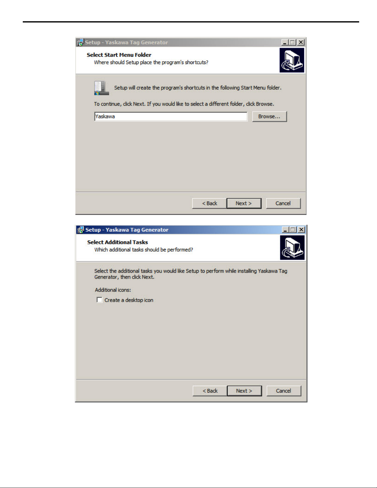
Click Next to continue to create a Yaskawa Start Menu folder or Browser to select a different folder.
5.
Click Next or check the box to create a desktop icon.
6.
YASKAWA TOEP YAICOM 20A Tag Generator User Guide
7
Page 8

3 Install Software and Create a New Project
Click Install to complete the installation.
7.
Click Finish to launch the Tag generator software.
8.
8
YASKAWA TOEP YAICOM 20A Tag Generator User Guide
Page 9

The initial screen is displayed.
9.
3 Install Software and Create a New Project
Click the “New Project” button on the “Yaskawa Tag Generator” window.
10.
YASKAWA TOEP YAICOM 20A Tag Generator User Guide
Figure 1 New Project Button
9
Page 10

3 Install Software and Create a New Project
Select the radio button within the New Project dialog box to choose the software that will use the generated tag file.
11.
Select “Logix Designer/RSLogix 5000” for EtherNet/IP or DeviceNet protocols.
Select “TIA Portal” for PROFINET or PROFIBUS protocols.
Figure 2 New Project Dialog Window
Type a project name in the “Project Name” textbox.
12.
Click the “New Project” button.
13.
Refer to EtherNet/IP or DeviceNet Projects on page 11 for projects that utilize Logix Designer/RSLogix 5000.
14.
Refer to PROFINET or PROFIBUS Projects on page 19 for projects that utilize TIA Portal software.
10
YASKAWA TOEP YAICOM 20A Tag Generator User Guide
Page 11

4 EtherNet/IP or DeviceNet Projects
This section describes procedures for EtherNet/IP or DeviceNet projects and how to:
• add one or more nodes
• edit an EtherNet/IP node
• edit a DeviceNet node
• modify tag names
• edit, clone or delete a node
• build a tag list
• and import tags into Logix Designer/RSLogix 5000.
u
Add a Node
Click the “Add New Node” button on the Tag Generator Main Screen.
1.
4 EtherNet/IP or DeviceNet Projects
Click the radio button to choose the network type, next click the drop-down list to choose the communication option
2.
installed on the Yaskawa drive.
Click the "Next" button.
3.
Proceed to Refer to Edit an EtherNet/IP Node on page 12 for an EtherNet/IP network.
4.
Proceed to Refer to Edit a DeviceNet Node on page 13 for a DeviceNet network.
YASKAWA TOEP YAICOM 20A Tag Generator User Guide
Figure 3 Add New Node Button
Figure 4 Add New Node Dialog
11
Page 12

4 EtherNet/IP or DeviceNet Projects
u
Edit an EtherNet/IP Node
Follow this procedure to edit node settings for an EtherNet/IP node.
Match the fields in the "Edit EtherNet/IP Node" dialog to the configuration in Logix Designer/RSLogix 5000 software.
1.
Click the "Finish" button when all values are set.
NOTICE: Abnormal Equipment Operation. Match the fields in the "Edit EtherNet/IP Node" dialog to the configuration in Logix
Designer/RSLogix 5000 software. Invalid or mismatched tags may cause erroneous operation.
Figure 5 Edit EtherNet/IP Node Dialog
Table 2 Field Descriptions for the Edit EtherNet/IP Node Dialog
Dialog Field Description
Data Format (Display only):
Pair Assemblies (Checkbox):
Output Assembly (Drop-down list): Select the desired Output Assembly.
Input Assembly (Drop-down list): Select the desired Input Assembly when the “Pair Assemblies” checkbox is deselected.
Scope (Textbox):
Node Name (Textbox):
Field displays tag data size. The tags are created based on the data size displayed here. This
field is for display only and not configurable in the Tag Generator. The data in this display field
must be manually mapped in RSNetWorx.
Select this checkbox when using matching assemblies. Example: Output Assembly 20 is
typically paired with Input Assembly 70. Deselect this checkbox to use differing assemblies.
Specify the scope for this node's tags. Leave blank to use the controller scope. The default
value for this field is “MainProgram”.
Enter the name of the node in this text box to match the node name in Logix Designer/RSLogix
5000.
12
YASKAWA TOEP YAICOM 20A Tag Generator User Guide
Page 13

u
Edit a DeviceNet Node
Follow this procedure to edit node settings for an DeviceNet node.
Match the fields in the "Edit DeviceNet/IP Node" dialog to the configuration in Logix Designer/RSLogix 5000 software.
1.
Click the "Finish" button when all values are set.
NOTICE: NOTICE: Abnormal Equipment Operation. Match the fields in the "Edit DeviceNet Node" dialog to the configuration in
Logix Designer/RSLogix 5000 software. Invalid or mismatched tags may cause erroneous operation.
4 EtherNet/IP or DeviceNet Projects
Table 3 Field Descriptions for the Edit DeviceNet Node Dialog
Dialog Field Description
Data Format (Display only):
Pair Assemblies (Checkbox):
Output Assembly (Drop-down list): Select the desired Output Assembly.
Input Assembly (Drop-down list): Select the desired Input Assembly when the “Pair Assemblies” checkbox is deselected.
Scope (Textbox):
YASKAWA TOEP YAICOM 20A Tag Generator User Guide
Figure 6 Edit DeviceNet Node Dialog
Field displays tag data size. The tags are created based on the data size displayed here.
This field is for display only and not configurable in the Tag Generator. The data in this display
field must be manually mapped in RSNetWorx.
Select this checkbox when using matching assemblies.
Example: Output Assembly 20 is typically paired with Input Assembly 70. Deselect this
checkbox to use differing assemblies.
Specify the scope for this node's tags. Leave blank to use the controller scope. The default
value for this field is “MainProgram”.
13
Page 14

4 EtherNet/IP or DeviceNet Projects
Dialog Field Description
Node Name (Textbox):
Module Slot # (Textbox): Specify the slot number of the module that will indirectly reference the DeviceNet tags.
Location (Textbox):
Input and Output Assembly Offsets
(Textbox, 2 each):
Include COS (Checkbox): Select this checkbox to include the “Change of State” data if required.
COS Offset (Textbox):
u
Modify Tag Names
Enter the name of the node in this text box to match the node name in Logix Designer/
RSLogix 5000.
Enter "Local" in this textbox if the DeviceNet scanner is on the same chassis as the CPU.
Otherwise enter the name of the remote scanner/adapter in this textbox.
Enter the Input and Output Assembly offsets to match the data mapping location within the
PLC memory.
NOTICE: Abnormal Equipment Operation. Ensure the Input and Output Assembly
offset values match the data mapping location in the PLC memory. Invalid or
mismatched values will report improper data back to the tags and may cause erroneous
operation.
Enter the offset value to match the data mapping location in the PLC memory when the
“Include COS” checkbox is selected.
The Tag Generator provides the option to modify tag names and descriptions to for each application. Follow these steps to
modify tag names.
Select the “Tags” tab in the “Yaskawa Tag Generator” dialog, then select a tag to edit and click the “Edit Selected
1.
Tag” button to display the "Edit Tag" dialog.
14
Figure 7 Yaskawa Tag Generator Dialog
YASKAWA TOEP YAICOM 20A Tag Generator User Guide
Page 15

4 EtherNet/IP or DeviceNet Projects
Enter the new tag information in the “New Tag Description” and “New Tag Name” text boxes to modify the existing
2.
tag data.
The “Current Tag Description” and “Current Tag Name” text boxes display the currently assigned tag description and
name.
Optional: Click the “Reset to Defaults” button to reset the values in the “New Tag Description” and “New Tag Name”
text boxes to the default values shown in the “Default Tag Description” and “Default Tag Name” text boxes.
Figure 8 Edit Tag Dialog
u
Edit, Clone or Delete Nodes (Optional)
Edit a node: Double-click on a node in the list or select the node and click the “Edit Selected Node” button to edit
1.
existing nodes.
Clone a node: Use the Clone feature to easily duplicate several nodes.
2.
Select a node within the "Tags" tab and click the “Clone Selected Node” button, and give the new node a name to
clone the node.
Delete a node: Select a node within the "Tags" tab and click the “Delete Selected Node” button to remove a node.
3.
YASKAWA TOEP YAICOM 20A Tag Generator User Guide
Figure 9 Edit, Clone or Delete Nodes
15
Page 16

4 EtherNet/IP or DeviceNet Projects
u
Build a Tag List
Follow these steps to build the tag list.
Ensure all project modifications are made, nodes are added, and tag names are defined.
1.
Determine the location of the output file.
2.
Click the “Change Output File” button on “Yaskawa Tag Generator” dialog to specify the output file name and location.
3.
The default location and file name is C:\Users\Username\Documents\tag_list.csv.
4.
Figure 10 Change Output File Button
Specify the "Save As" folder location and "File name" in the “Save As” dialog and click the "Save" button.
5.
Note: The Tag Generator will automatically use extension “.csv” for EtherNet/IP or DeviceNet projects.
16
Figure 11 "Save As" Dialog for Tag Name and File Location
YASKAWA TOEP YAICOM 20A Tag Generator User Guide
Page 17

4 EtherNet/IP or DeviceNet Projects
Click the “Build Tag List” button within the Yaskawa Tag Generator dialog, next click "OK" within the resulting Success
6.
dialog.
Figure 12 Successful Creation of an Output File
Example of a Logix Designer/RSLogix 5000 *.CSV output file.
7.
Figure 13 Example: Logix Designer/RSLogix 5000 *.CSV Output File
YASKAWA TOEP YAICOM 20A Tag Generator User Guide
17
Page 18

4 EtherNet/IP or DeviceNet Projects
u
Import Tags into Logix Designer/RSLogix 5000
Follow this procedure to import tags from the Tag Generator into Logix Designer/RSLogix 5000.
Open the PLC project in Logix Designer/RSLogix 5000.
1.
NOTICE: Ensure Logix Designer/RSLogix 5000 is offline, as tags can only be imported into Logix Designer/RSLogix 5000 in offline
mode.
Select “Import”, then “Tags and Logic Comments…” using the “Tools” drop-down menu to open the Import dialog.
2.
Refer to Figure 14.
Figure 14 Import Tags into Logix Designer/RSLogix 5000
Browse to the *.CSV tag file, select it, and click the Import button using the Import dialog. Refer to Figure 15.
3.
Figure 15 Select the *.CSV file for import
18
YASKAWA TOEP YAICOM 20A Tag Generator User Guide
Page 19

5 PROFINET or PROFIBUS Projects
5 PROFINET or PROFIBUS Projects
After creating a new project, the next step to create new tags with the Tag Generator is to add one or more nodes. Follow these
steps to add a node. Repeat these steps to add multiple nodes.
This section describes procedures for PROFINET or PROFIBUS projects and how to:
• add one or more nodes
• edit a PROFINET node
• edit a PROFIBUS node
• modify tag names
• edit, clone or delete a node
• build a tag list
• and import tags into TIA Portal software.
u
Add a Node
Follow these steps to add one or more nodes.
Click the “Add New Node” button on the Tag Generator Main Screen.
1.
Click the radio button to choose the network type, next click the drop-down list to choose the communication option
2.
installed on the Yaskawa drive.
Click the "Next" button.
3.
Refer to Edit a PROFINET Node on page 20 for a PROFINET network.Refer to Edit a PROFIBUS Node on
4.
page 21 for a PROFIBUS network.
YASKAWA TOEP YAICOM 20A Tag Generator User Guide
Figure 16 Add New Node Button
Figure 17 Add New Node Dialog
19
Page 20

5 PROFINET or PROFIBUS Projects
u
Edit a PROFINET Node
Follow this procedure to edit node settings for a PROFINET node.
Match the fields in the "Edit PROFINET Node" dialog to the configuration in TIA Portal software. Click the "Finish"
1.
button when all values are set.
NOTICE: Abnormal Equipment Operation. Match the fields in the "Edit PROFINET Node" dialog to the configuration in TIA Portal
software. Invalid or mismatched tags may cause erroneous operation.
Table 4 Field Descriptions for the Edit PROFINET Node Dialog
Dialog Field Description
Data Address-Input/Output (Textbox):
Tag Prefix (Textbox):
Module (Drop-down list):
Yaskawa or PROFIdrive (Radio button):
Figure 18 Edit PROFINET Node Dialog
Specifies the starting address for input and output data. Enter addresses in these text boxes
to match the addresses configured in TIA Portal.
Enter a value to uniquely identify the node tags from other nodes. The prefix may consist
of a station name or a node number of the device. This text will be used as a prefix for every
tag on the node.
Select the I/O Module that will be used with this node. Ensure the selected module matches
the module configured in the TIA Portal.
Select the radio button next to the value that matches the control and status configuration
in TIA portal.
20
YASKAWA TOEP YAICOM 20A Tag Generator User Guide
Page 21

u
Edit a PROFIBUS Node
Follow this procedure to edit node settings for a PROFIBUS node.
Match the fields in the "PROFIBUS Node" dialog to the configuration in TIA Portal software. Click the "Finish" button
1.
when all values are set.
NOTICE: Abnormal Equipment Operation. Match the fields in the "Edit PROFIBUS Node" dialog to the configuration in TIA Portal
software. Invalid or mismatched tags may cause erroneous operation.
5 PROFINET or PROFIBUS Projects
Table 5 Field Descriptions for the Edit PROFIBUS Node Dialog
Dialog Field Description
Data Address-Input/Output (Textbox):
Tag Prefix (Textbox):
Conventional or PPO (Radio button):
Format (Drop-down list):
PZD1 (Radio button):
Figure 19 Edit PROFIBUS Node dialog
Specifies the starting address for input and output data. Enter addresses in these text boxes
to match the addresses configured in TIA Portal.
Enter a value to uniquely identify the node tags from other nodes. The prefix may consist of a
station name or a node number of the device. This text will be used as a prefix for every tag
on the node.
Select the radio button to match the PROFIBUS-DP Data Format Selection parameter F6-32
in the drive.
Select a received data format from the drop-down list to match the module configured in TIA
Portal. List choices vary based on the Conventional or PPO selection.
Choose the appropriate radio button for use with the PLC program. Select “PZD1 = Ctrl/Sts
Word” for control/status word. Select “PZD1 = Configurable” for configurable word or alternate
purpose. This radio button is enabled when PPO is set in the “Format” field. The Tag Generator
will generate multiple tags for each bit or a single tag for the whole word. PZD1 defaults to
Control (STW) and Status (ZDW) words.
YASKAWA TOEP YAICOM 20A Tag Generator User Guide
21
Page 22

5 PROFINET or PROFIBUS Projects
u
Modify Tag Names
The Tag Generator provides the option to modify tag names and descriptions for each application. Follow these steps to modify
tag names.
Select the “Tags” tab in the “Yaskawa Tag Generator” dialog, then select a tag to edit and click the “Edit Selected
1.
Tag” button to display the "Edit Tag" dialog.
Figure 20 Yaskawa Tag Generator Dialog
Enter the new tag information in the "New Tag Description" and "New Tag Name" text boxes to modify the existing
2.
tag data.
The “Current Tag Description” and “Current Tag Name” text boxes display the currently assigned tag description and
name.
Optional: Click the “Reset to Defaults” button to reset the values in the “New Tag Description” and “New Tag Name”
text boxes to the default values shown in the “Default Tag Description” and “Default Tag Name” text boxes.
22
Figure 21 Edit Tag Dialog
YASKAWA TOEP YAICOM 20A Tag Generator User Guide
Page 23

u
Edit, Clone or Delete Nodes (Optional)
Edit a node: Double-click on a node in the list or select the node and click the “Edit Selected Node” button to edit
1.
existing nodes.
Clone a node: Use the Clone feature to easily duplicate several nodes.
2.
Select a node within the "Tags" tab and click the “Clone Selected Node” button, and give the new node a name to
clone the node.
Delete a node: Select a node within the "Tags" tab and click the “Delete Selected Node” button to remove a node.
3.
5 PROFINET or PROFIBUS Projects
Figure 22 Edit, Clone or Delete Nodes
YASKAWA TOEP YAICOM 20A Tag Generator User Guide
23
Page 24

5 PROFINET or PROFIBUS Projects
u
Build a Tag List
Ensure all project modifications are made, nodes are added, and tag names are defined.
1.
Determine the location of the output file.
2.
Click the "Change Output File" button on "Yaskawa Tag Generator" dialog to specify the output file name and location.
3.
The default location and file name is C:\Users\Username\Documents\tag_list.xlsx.
4.
Figure 23 Yaskawa Tag Generator Dialog (Change output file)
Specify the "Save As" folder location and "File name" in the “Save As” window dialog and click the "Save" button.
5.
Note: The Tag Generator will automatically use extension “.xlsx” for PROFIBUS or PROFINET projects.
24
Figure 24 "Save As" Dialog for Tag File Location and File Name
YASKAWA TOEP YAICOM 20A Tag Generator User Guide
Page 25

5 PROFINET or PROFIBUS Projects
Click the “Build Tag List” button within the Yaskawa Tag Generator dialog, next click "OK" within the resulting Success
6.
dialog.
Figure 25 Successful Creation of an Output File
Example of a TIA Portal *.XLSX output file.
7.
Figure 26 TIA Portal Example File
YASKAWA TOEP YAICOM 20A Tag Generator User Guide
25
Page 26

5 PROFINET or PROFIBUS Projects
u
Import Tags into TIA Portal Software
Follow this procedure to import tags from the Tag Generator into TIA Portal software. Refer to Figure 27
Open the PLC project in TIA Portal.
1.
Expand the target PLC in the Devices project tree.
2.
Expand PLC tags.
3.
Double-click “Show all tags” in the Devices project tree.
4.
Figure 27 Expanded Devices Project Tree within TIA Portal
Click the Import icon on the main window tool bar to open the Import from Excel dialog. Refer to Figure 28.
5.
Click the “…” icon in the “Import from Excel” dialog to browse to the *.XLSX tag file. Refer to Figure 29.
26
Figure 28 Import From Excel Dialog
YASKAWA TOEP YAICOM 20A Tag Generator User Guide
Page 27

Figure 29 File Selection Browse Dialog
5 PROFINET or PROFIBUS Projects
Select the *.XLSX tag file for import and click the Open button in the Open dialog to import the file. Refer to Figure
6.
29
End
7.
YASKAWA TOEP YAICOM 20A Tag Generator User Guide
27
Page 28

Revision History
MANUAL NO.
Example:
TOEP YAICOM 20A
Published in USA May 2015 15-5
Date of publication
Date of original publication
The revision dates and the numbers of the revised manuals appear on the bottom of the back cover.
Date of Publication
Revision
Number
Section Revised Content
May 2015 - - First Edition. This manual supports software version 2.0.0.
28
YASKAWA TOEP YAICOM 20A Tag Generator User Guide
Page 29

This Page Intentionally Blank
YASKAWA TOEP YAICOM 20A Tag Generator User Guide
29
Page 30

Tag Generator Support Tool
for Logix Designer/RSLogix 5000 & TIA Portal
User Guide
YASKAWA AMERICA, INC.
2121 Norman Drive South, Waukegan, IL 60085, U.S.A.
Phone: (800) YASKAWA (927-5292) or 1-847-887-7000 Fax: 1-847-887-7310
http://www.yaskawa.com
YASKAWA ELÉTRICO DO BRASIL LTDA.
Avenida Piraporinha 777, Diadema, São Paulo, 09950-0000, Brasil
Phone: 55-11-3585-1100
http://www.yaskawa.com.br
YASKAWA CANADA, INC.
298 Avenue Labrosse, Pointe-Claire, Quebec H9R 5L8, Canada
Phone: (800) 854-4124 or 1-514-693-6770 Fax: 1-514-693-9212
http://www.yaskawa.com
Fax: 55-11-3585-1187
YASKAWA AMERICA, INC.
In the event that the end user of this pro duct i s to be the military and said product is to be employed in any weapons system s or the manufactur e
thereof, the export will fall under t he relevant regulatio ns as stipulated in the Foreign Exchange and Foreign Trade Regula tions. Therefore, be sure
to follow all procedures and s ubmit all relevant documentation ac cording to any and all ru les, regula tions and laws that may ap ply.
Specifications are subject to change without notice for ongoing product modifications and improveme nts.
© 2015 YASKAWA AMERICA, INC. All rights reserved.
MANUAL NO. TOEP YAICOM 20A
Published in USA May 2015 15-5
 Loading...