

Page 1

THK VLA Indexer
Page 2

Page 3

Table of Contents
Introduction ................................................................1
Opening Screen ..........................................................2
To create a new project ..........................................3
To open an existing project .....................................3
THK Wizard .................................................................4
Main Screen ..............................................................11
Modules .....................................................................11
Sequences ................................................................13
Sequence Events ......................................................14
Start By Events: Expression, Input, and Variable .14
Change Events: Accel and Speed ........................14
Loop Events: Expression and Fixed Number ........14
Move Events: Start and End .................................15
Set Events: Output and Variable ...........................15
Wait For Events: Absolute Position, Distance, Input,
Time, and Variable ................................................16
Skip Event .............................................................16
Sequence Rules ........................................................16
Variables ...................................................................17
Menu Items ...............................................................17
Program Flow ...........................................................17
Sequence Terms .......................................................20
Hardware ...................................................................21
Start-up .................................................................21
Mounting Orientation .............................................21
Power/Connections Wiring - Single Phase ...........23
Power/Connections Wiring - Three Phase ............24
I/O Connections (50-pin CN5) ...............................25
Digital I/O ..............................................................26
Serial Communication ...........................................29
i
Page 4

ii
Page 5

THK VLA Indexer
Introduction
The THK VLA Indexer allows a user to “program” motion on a
VLA slide without ever learning or knowing a programming
language.
The user simply answers a series of questions about the slide
being used, the load connected to it, and what will cause it to
energize and home. Then the user creates one or more sequences
that the slide is required to perform using pre-defined events like
“Move Start”. Once all of the parameters are entered into the
events chosen by the user, a program can be generated and sent to
the controller by compiling and downloading.
The program created and downloaded will begin running
immediately. It will set all necessary parameters, wait for the
condition chosen to energize the servomotor, and then enter
either the manual or automatic mode. The manual or automatic
mode is dictated by the state of input 8. If input 8 is high or off
the program enters Manual mode, if it is low or on, Auto mode is
run; but only after the servo is enabled the first time.
Manual mode allows the user to enable and disable the servo (if
the choice to energize the servo was by input or variable), and
once the servo is enabled, to jog forward or reverse.
Auto mode will home the servo once after a po wer-up when the
condition to home is true, and then run sequences when their
individual start conditions are true. If there is more than one
sequence defined and the condition to start each sequence is true,
then the sequences will be run in order one after the other, and
will continue to run until the start condition is false. Remember,
in order to enter the Auto mode, the servo must be energized.
1
Page 6
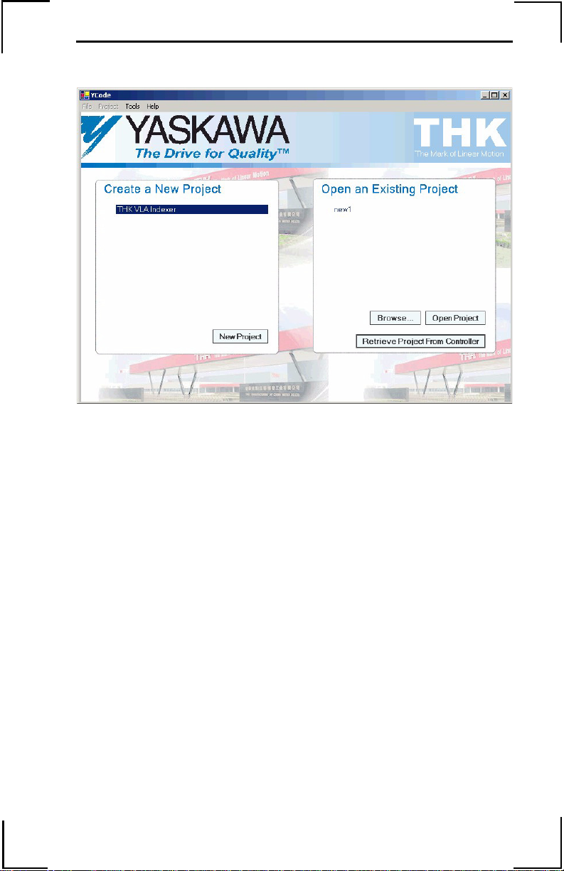
Opening Screen
When the application is started, the user is presented with the
opening screen, which allows the user to create a new project or
open an existing project.
2
Page 7
To create a new project
Select the template name “THK VLA Indexer” and click on the
New Project button.
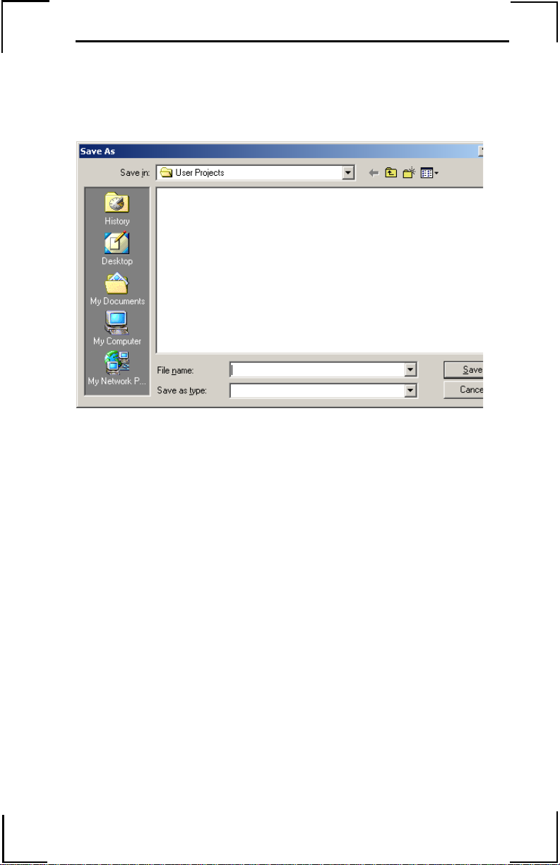
Enter a project name, select “OK”, and the THK Wizard will
appear.
To open an existing project
An existing project can be opened by selecting it from the list and
clicking on “Open Project”, or by clicking on “Browse…” to
locate the ***.yap file. A project can also be opened from the
controller (if it was previously saved using the save project to
controller option) by selecting “Retrieve Project From
Controller” while connected online.
3
Page 8
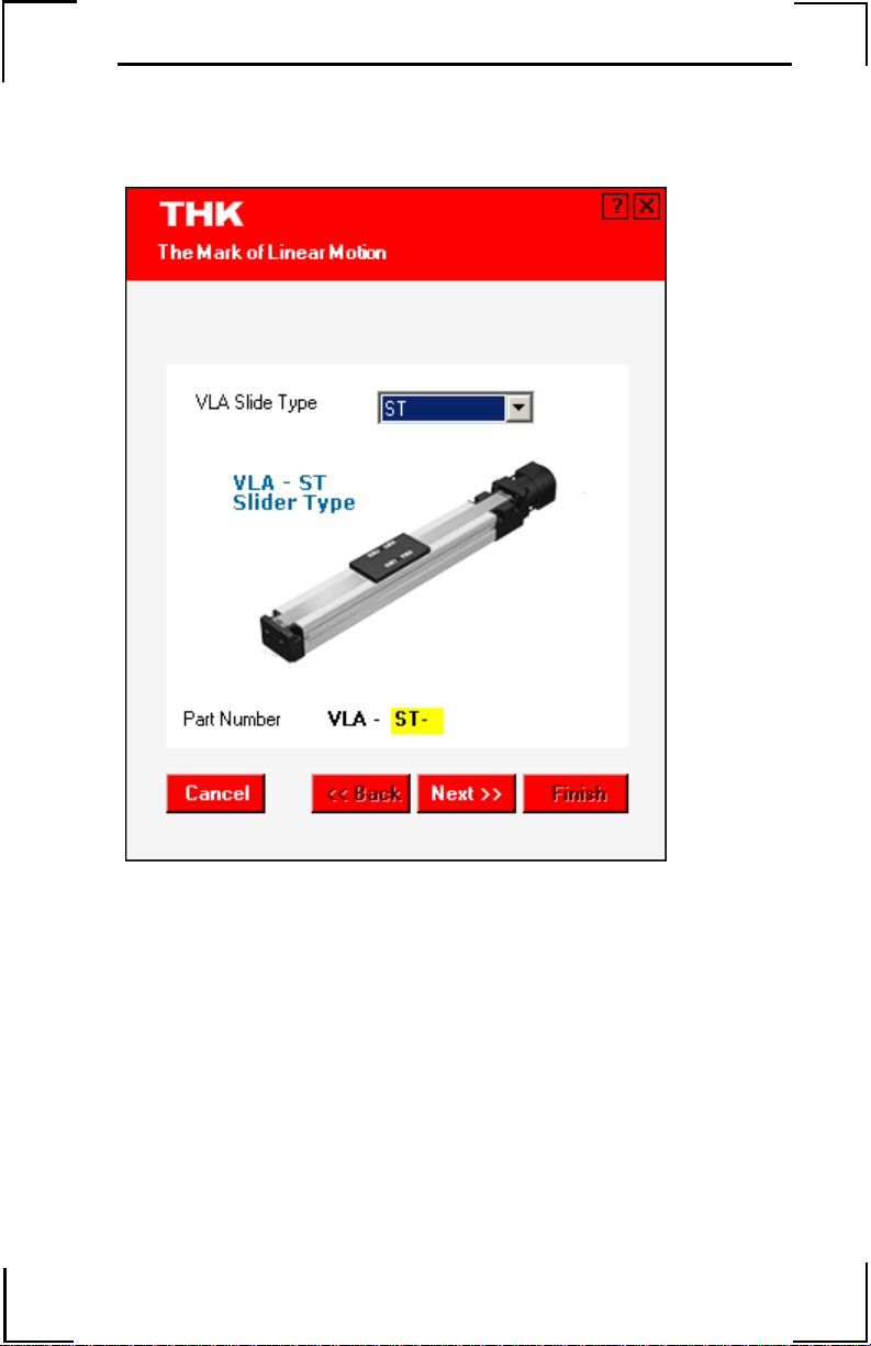
THK Wizard
The THK Wizard will guide the user through entering the THK
part number of the VLA slide and selecting the load connected.
Locate the part number of the VLA slide. The part number is
located on the left side of the actuator if the motor is positioned
on the left.
Select the type of VLA slide by choosing either ST or CT. The
picture changes as the selection is changed. Navigate through the
screens using the Next button to advance.
4
Page 9
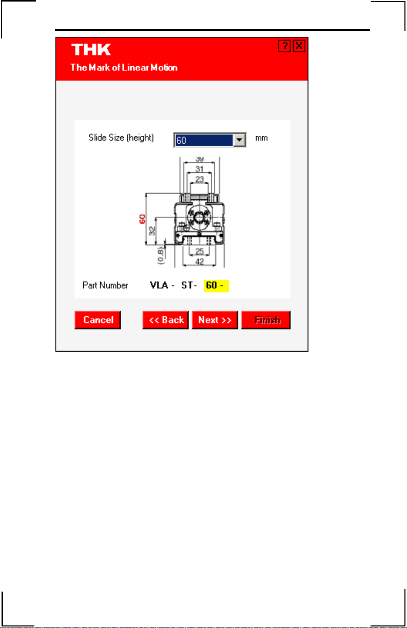
Next enter the Slide Height.
5
Page 10
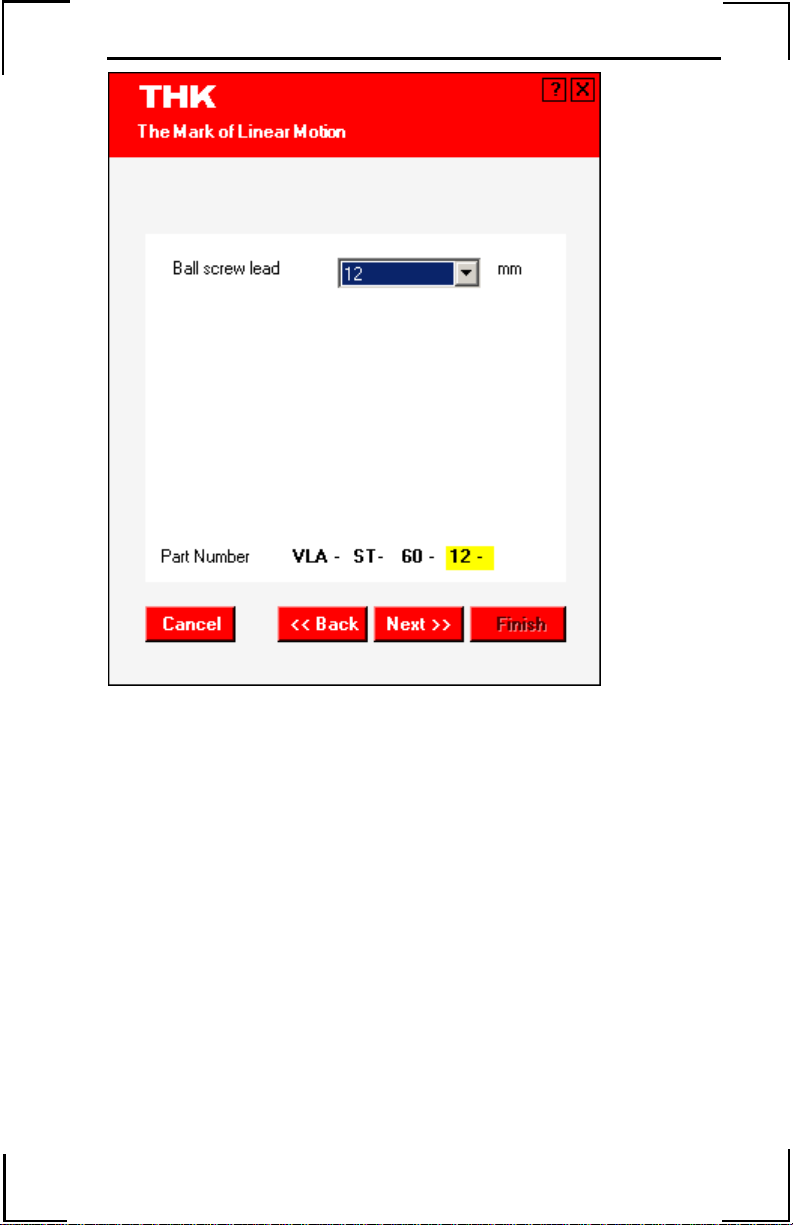
A ball screw lead must be selected if using an ST type slide. For
the CT type, accept the 12mm default.
6
Page 11
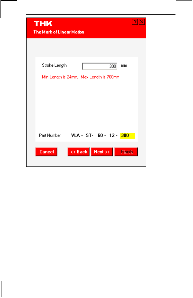
Enter the Stroke Length.
7
Page 12

Specify the Load Direction and Weight.
8
Page 13

Select the Units.
9
Page 14

Select the side on which the actuator will home and click on
“Finish”.
10
Page 15

Main Screen
Project Tree
Main Window
Progress
Window
The main screen features a Project Tree that is used to display
items in the main window and a Progress Window that highlights
the step currently being performed. Clicking on Project Tree will
access the main folders that make up the program (modules,
sequences, and variables).
Modules
Clicking on “Modules” will display the setup questions for the
application. There are two ways to view the questions, one at a
time (Wizard View), or all at once (Table View). Wizard View
displays questions one at a time with question specific help at the
bottom of the main window. This allows the user to navigate back
and forth using the Previous and Next buttons. Wizard View is
the default view and is shown in the main window above.
11
Page 16

Table View displays all of the questions at once, with all but the
last unanswered question grayed out. This focuses the user’s
attention on the last unanswered question while allowing viewing
of the entire set of questions that have been answered.
Clicking on the name of an individual module will filter the
questions in Table View, displaying only the questions in that
module.
12
Page 17

Sequences
To create a sequence, right-click the word “Sequence” in the
Project Tree and select “Add Sequence”.
Sequence view with no
sequences defined
Sequences are given meaning by adding events. To add an event,
select one from the drop down list at the top of the screen and
click the Add Event (+) button.
Delete Event
Move Event, Up
or Down
List of Events
Add Event
All sequences must begin with a Start By event (Input,
Expression, or Variable) and there must be only one Start By
event so place one of these events in the first position of the
sequence window.
13
Page 18

Sequence Events
Start By Events: Expression, Input, and Variable
• Start by Expression must be valid comparison expressions in
the form of x=2, y>7, or similar items that evaluate to Boolean
true or false. This is an advanced event allowing anything to be
specified, and is NOT checked for errors. If unsure, avoid using
this event.
• Start by Input asks the user to specify an input number and
state or transition of the input. Valid input numbers are from
1~7 (and 2000~2255 if using Ethernet I/O). Specifying a state
will cause the sequence to run when the input is On or Off,
while specifying a transition will wait until the edge or change
of the input occurs.
• Start by Variable requires the user to enter a variable name
and value. Valid variable names are 1 to 8 characters in length,
case sensitive, and accept alphanumeric characters and the
underscore. The value entered is the value that will cause the
sequence to run.
The user adds the remaining events as needed to form the custom
sequence required for the application.
Change Events: Accel and Speed
These events are useful for changing values while moving.
• Change Accel allows the user to specify a new acceleration.
• Change Speed allows the user to specify a new speed.
Loop Events: Expression and Fixed Number
A Loop event will cause the program to loop back to a previous
labeled event.
An event is labeled by entering a name for the event in the
response column on the row of the event name. The Loop event
will only allow program flow to return upwards. Program flow
cannot be returned to the start event, or within a Move Start,
Move End pair.
14
Page 19

• Loop Expression will continue to loop while the expression is
true. Expressions are valid comparisons in the form of x=2,
y>7, or similar items that evaluate to Boolean true or false. This
is an advanced event allowing anything to be specified, and is
NOT checked for errors. If unsure, avoid using this event.
• Loop Fixed Number will loop for the number of times
specified.
Move Events: Start and End
• Move Start has the user specify all of the move parameters.
! Acceleration is entered in user units.
! Deceleration is entered in user units.
! S-Curve is the amount of motion smoothing applied to the
move. A value of 1 indicates no S-Curve and .004
indicates the maximum S-Curve. Applying S-Curve
smooths the acceleration and lengthens the move time.
! Speed is entered in user units.
! Move Type can either be absolute or incremental.
Absolute moves go to that absolute position (based on
where the home position is), while incremental moves
advance a certain distance from where they are currently.
! Position is entered in user units.
• Move End requires selection of either profiler or encoder.
! Profiler will wait until the controller finishes calculating
the move and sends the commands to the motor.
! Encoder will wait for the actual position of the motor to
reach the calculated position.
Set Events: Output and Variable
• Set Output specifies an output number and a state (either on or
off).
• Set Variable specifies a variable name and value.
15
Page 20

Wait For Events: Absolute Position, Distance, Input, T ime, and Variable
• Wait for Absolute Position waits for the encoder to reach the
position specified.
• Wait for Distance waits for the encoder to see a movement of
the distance specified from the start of the move.
• Wait for Input waits for the input to be at the state specified,
or for the transition to occur.
• Wait for Time waits for an amount of time specified in
milliseconds (where 1000 = 1 second)
• Wait for Variable waits for the variable specified to be set to
that value.
Skip Event
Allows the program to conditionally skip one or more events.
Sequence Rules
1. All sequences must begin with a Start By event, and there must be only one Start By event. So place one of these events in the first position of the Sequence window.
2. The program cannot loop back to a Start By event.
3. Every Move Start event must have one and only one Move End event.
4. Moves cannot be nested. If a Move Start event is placed in a sequence, then a Move End event must be placed in that sequence before another Move Start event.
5. The events Wait for Absolute Position and Wait for Distance must be placed within a Move Start, Move End pair.
6. If a Loop event is used, there must be a previous event with a label to loop back to.
7. If a Skip event is used, there must be a later event with a label to skip to.
16
Page 21

Variables
When variables are entered into the program, they automatically
appear in the variable table. Variables in the program must be
initialized. Specify a value for all variables used in the program
or the compiler will prompt for values.
Menu Items
The File menu contains the standard items that allow the user to
create a new project (New), open an existing project (Open), save
the current project (Save), and create a copy of the current project
with a new name (Save As).
The Project menu allows the user to create a downloadable
program file (Compile), to download the executable program to
the controller (Send to Controller/Download), and to save the
current project (Send Project File to Controller) on the controller.
All of the questions in the modules must be answered and at least
one move sequence with a minimum of one event existing before
the user is allowed to compile.
The Tools menu allows the user to rerun the VLA slide selection
Wizard if the user needs to change the model number.
Program Flow
The program will begin running immediately after it is
downloaded or whenever the power is cycled. It will set all
necessary parameters, wait for the condition chosen to energize
the servomotor, and then enter either the manual or automatic
mode. If input 8 is High/Off, the program enters Manual mode. I f
it is Low/On, Auto mode is engaged; but only after the servo is
enabled the first time.
Manual mode allows the user to enable and disable the servo (if
the choice to energize the servo was by input or variable), and
once the servo is enabled, to jog forward or reverse. Jogging
forward or reverse is achieved by pressing the reverse or forward
limit switch respectively. Jogging will continue for as long as the
switch is held on.
17
Page 22

Auto mode requires that the servo be homed once after a powerup. If the servo has not been homed, no sequences will run. When
the condition to home is true, the servo will find the home
position and then run sequences when their individual start
conditions are true. If there is more than one sequence defined
and the condition to start each sequence is true, then the
sequences will be run in order one after the other, and will
continue to run until the start condition is false. Remember, if
Input 8 is High/Off, the program enters the Manual mode. If it is
Low/On, the Auto mode is engaged, but only after the servo is
enabled the first time.
18
Page 23

Auto Mode
Run Sequence 1
Run Sequence n
Yes
Yes
Power On
Set servo gains
Set parameters
Set internal
variables
Is servo on
condition true
Yes
Turn Servo On
Is Manual input
on
No
Home condition
= True & NOT
HOMED
No
Sequence 1
start = True &
HOMED
No
Sequence n
start = True &
HOMED
No
No
Manual Mode
Yes
Is Servo-On
condition True
Start Home
Yes
Yes
Home Complete
No
Home timeout
No
Yes
Set Error
End
Yes
Turn Servo On
Is Jog + input
on
No
Is Jog - input
on
No
Turn Servo Off
No
Jog forward at +
Yes
Jog speed
Jog reverse at -
Yes
Jog speed
Program Flow
19
Page 24

Sequence Terms
• Encoder: The physical device used to track position mounted
on the motor.
• Expression: Must be valid comparison expressions in the form
of x=2, y>7, or similar items that evaluate to Boolean true or
false. This field is NOT checked for errors. If unsure, avoid
using events with this parameter.
• Input: Valid input numbers are from1~7 (and 20 00~2255 if
using Ethernet I/O). Specifying a state will cause the event to
run when the input is on or off while specifying a transition will
wait until the edge or change of the input occurs (i.e. the input
must go from 1 to 0 or from 0 to 1 before the event will run).
• Label: Labels are applied to events by entering characters in the
response column next to the event name.
• Output: Valid output numbers are from1~4 (and 2000~2255 if
using Ethernet I/O).
• Variable: Valid variable names are 1 to 8 characters in length,
case sensitive, and accept alphanumeric characters and the
underscore. Variable values are in the range –
2147483648.9999 ~ 2147483647.9999 and have a fractional
resolution of 1/65536.
20
Page 25

Hardware
Start-up
Mounting the LEGEND-MC to the LEGEND Amplifier
1. Insert the lower two mounting notches of the LEGEND-MC
into the mounting holes at the bottom of the right side of the
LEGEND.
2. Push the LEGEND-MC in the direction indicated by the
arrow in the figure below, and insert the upper mounting
notches of the LEGEND-MC into the upper mounting holes
on the right side of the LEGEND.
Mounting Orientation
Mount the LEGEND-MC and LEGEND vertically for proper
cooling, as shown below. Allow a minimum spacing of 10mm
around the left and right sides and 30mm around the top and bottom
of the LEGEND-MC/LEGEND unit.
21
Page 26

Front Panel Description
No. Name Description
(1) Power
ON
(2) Alarm/
Error
(3) CN6 9 pin male D-Sub serial port connector
(4) CN5 3M 50 pin high density I/O connector
(5) RST Reset switch. Causes the controller to
(6) Ethernet
status
(7) Ethernet
status
(8) CN4 10 BaseT Ethernet RJ485 Connector
(9) FG Frame ground spade terminal.
A lit green LED indicates that the
+5 VDC power supplied to the
LEGEND-MC controller from the
LEGEND amplifier is working.
A red LED that will flash on initially at
power-up and stay lit for approximately
1-8 seconds. After power-up, the LED
will illuminate for the following
reasons:
Position error occurs when the
measured value is greater than the
position error limit setpoint. Manual
reset of the controller, noise and/or a
failure in the processor can also
trigger this alarm for a short time. If
the error does not clear, please
contact your local Yaskawa
representative for assistance.
reboot, and load the application
program and parameters from flash.
A green LED that is lit when there i s an
Ethernet connection to the controller.
This LED tests only for the physical
connection, not for an active or
enabled link.
The yellow LED indicates traffic across
the Ethernet connection. This LED will
show both transmit and receive activity
across the connection. If there is no
Ethernet connection or IP address
assigned, the LED will flash at regular
intervals to show that the BOOTP
packets are being broadcast.
Connect to ground terminal on
LEGEND Amplifier
(2)
(3)
(4)
(8)
(5)
(7)
(9)
(1)
(6)
22
Page 27

Power/Connections Wiring - Single Phase
R
Noise Filter
T
Control
Power
ON
1MC
Servo ON
Control
Power
OFF
Servo
Power
OFF
Emergency
Stop
1MC
1MCCB
1MC
SUP
2MC
2MC
SUP
YASKAWA
C
N
6
LEGEND01
2MC
1MC
Note: The LEGEND-MC receives its power from the LEGEND amplifier through the side
interface connector, however, the digita l I/O receives its power from pins 46, 47,
48, and 49 on the I/O connector.
For maximum noise immunity, connect the FG to a ground terminal on the sub
panel or to the ground terminal on the LEGEND.
CHARGE POWER
L1
L2
L3
1
2
L1C
L2C
B1
B2
B3
U
V
W
C
N
5
C
N
1
C
N
2
R
S
T
C
N
4
F
G
23
Page 28

Power/Connections Wiring - Three Phase
R
T
S
1MCCB
Noise Filter
Control
Power
ON
1MC
Servo ON
Control
Power
OFF
Servo
Power
OFF
Emergency
Stop
1MC
1MC
SUP
2MC
2MC
1MC
2MC
YASKAWA
LEGEND01
CHARGE POWER
L1
L2
L3
1
2
L1C
L2C
B1
B2
B3
U
V
W
SUP
C
N
6
C
N
5
C
N
1
C
N
2
R
S
T
C
N
4
F
G
Note: The LEGEND-MC receives its power from the LEGEND amplifier through the side
interface connector, however, the digita l I/O receives its power from pins 46, 47,
48, and 49 on the I/O connector.
For maximum noise immunity, connect the FG to a ground terminal on the sub
panel or to the ground terminal on the LEGEND.
24
Page 29
I/O Connections (50-pin CN5)
CN5
1
1
2
3
4
5
6
7
8
9
10
11
12
13
14
15
16
17
18
19
20
21
22
23
24
25
26
27
28
29
30
31
32
33
34
35
36
37
38
39
40
41
42
43
44
45
46
47
48
49
50
Analog 1
Analog 2
+5 Filtered Output power (60 mA available)
-12 Filtered Output power (10 mA available)
+12 Filtered Output power (10 mA available)
Output compare (requires internal jumper)
External encoder AExternal encoder A+
External encoder BExternal encoder B+
Abort Input
Reverse limit switch
Home Input
Forward limit swi tc h
Reset Input
Digital Input 2
Digital Input 1
Digital Input 7
Digital Input 8
Digital Output 4
Digital Output 3
Digital Output 2
Digital Output 1
E STOP2
Analog Output
Digital Input 6
Digital Input 5
Digital Input 4
Digital Input 3
24V GND Input
24V Power Input
24V GND Input
24V Power Input
E STOP1
LEGEND-MC Signal Ground
25
Page 30

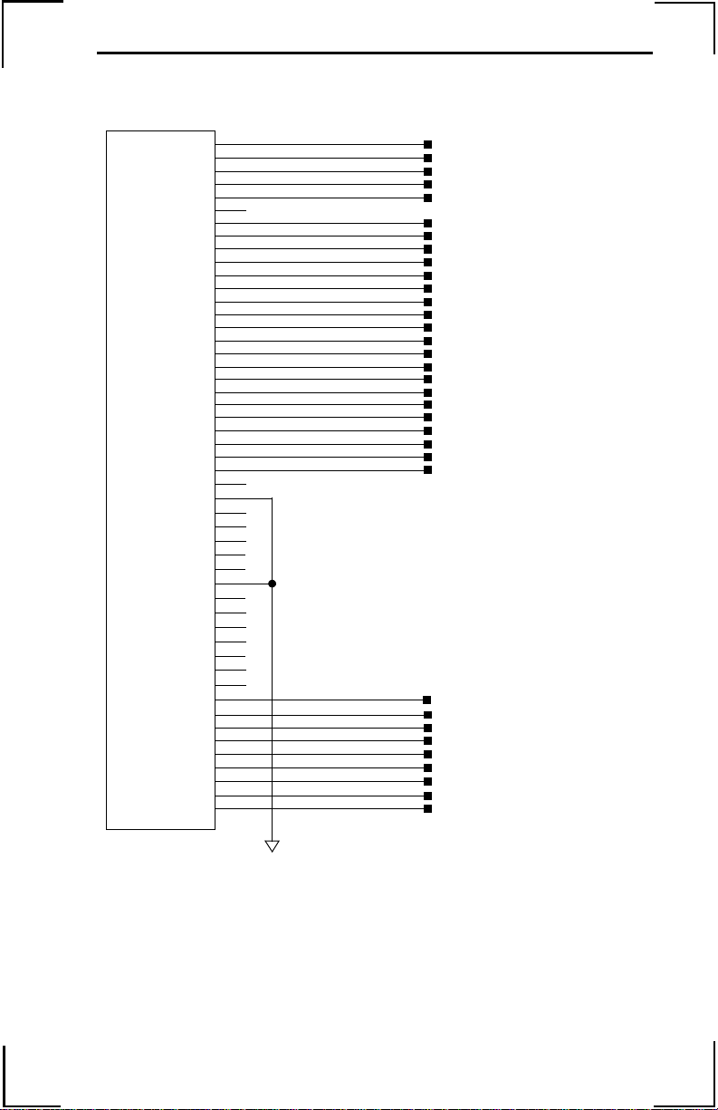
Digital I/O
Digital Input
Item Specifications
Number of Input Points 8
Input Format Sinking
Isolation Optical
Voltage 24 VDC ± 20%
Current Rating (ON) 5.3 mA to activate
Input Impedance 2.2k Ω
Operation Voltage Logic 0 <5V
OFF Current 0.9 mA or less
Response Time OFF to ON: <0.5 ms
Latch Response Time Less than 25 µsec
Minimum Latch Width 9 µsec
Note: Inputs float high unless the input is held low.
Internal Circuitry
Logic 1 >15V
ON to OFF: <1.5 ms
2.2k
LEGEND-MC I/O
Legend-MC I/O
Connector CN5
47
49
18
17
45
44
43
42
19
20
Field Wiring
Digital Input 1
(Main Latch)
Digital Input 2
(External Latch)
Digital Input 3
Digital Input 4
Digital Input 5
Digital Input 6
Digital Input 7
Digital Input 8
24VDC
26
Page 31

Digital Output
Item Specifications
Number of Output Points 4
Output Format Sinking
Output Classification Transistor Output
Isolation Optical
Load Voltage 24 VDC ± 20%
Load Current 200 mA/Output (600 mA if activated individually)
Response Time OFF to ON <0.25 ms
External Common Power 24 VDC ± 20% 15 mA
Common User Fuse Rating 1A
Individual User Fuse Rating 200 mA recommended
Note: The ULN 2803 output chip is capable of 600mA at a single output, or 800mA for
the four outputs simultaneously.
Internal Circuitry
PS2505-4
10k
ON to OFF <0.5 ms
ULN2803
LEGEND-MC I/O
Legend-MC I/O
Connector CN5
47
49
4.7k
24
23
22
21
Field Wiring
Digital Output 1
Digital Output 2
Digital Output 3
Digital Output 4
L
L
L
L
Fuse
24VDC
46
48
27
Page 32

Emergency Stop Chain
Internal Circuitry
VCC
U17
LEGEND-MC I/O
Legend-MC I/O
Connector CN5
Field Wiring
50
25
Q1
-EROUT
1k
Note: Note: The LEGEND-MC closes the relay contact under normal operating
conditions.
Ratings: 1.0A @ 24 VDC
0.5A @ 125 VAC
Maximum switching power: 62.5VA, 30W
2N7002
E STOP1
E STOP2
28
Page 33

Serial Communication
-
Item Specifications
Baud Rate 9600 or 19200 set by jumper JP1, default is 19200
Data Bits 8
Parity None
Stop Bits 1
Internal Circuitry
C1+
.1 UF
C1C2+
.1 UF
C2T1IN
T2IN
A1OUT
A2OUT
MAX232A
T1OUT
T2OUT
A1IN
A2IN
U7
V+
V-
LEGEND-MC Serial
Legend-MC Serial
Port Connector CN6
VCC
.1 UF
.1 UF
1
6
8
2
3
7
4
9
5
Field Wiring
CTS Output
CTS Output
CTS Output
Transmit Output
Receive Input
RTS Input
RTS Input
N/C
Signal Ground
Note: NOTE: Hardware handshaking must be used with the LEGEND-MC. If it is impos
sible to implement hardware handshaking, use a jumper between pins 1 and 4 in
the connector.
Note: NOTE: Do not connect pin 5 to a 24V ground.
29
Page 34

30
Page 35

Page 36

YASKAWA ELECTRIC AMERICA, INC.
Chicago-Corporate Headquarters 2121 Norman Drive South, Waukegan, IL 60085, U.S.A.
Phone: (847) 887-7000 Fax: (847) 887-7310 Internet: http://www.yaskawa.com
MOTOMAN INC.
805 Liberty Lane, West Carrollton, OH 45449, U.S.A.
Phone: (937) 847-6200 Fax: (937) 847-6277 Internet: http://www.motoman.com
YASKAWA ELECTRIC CORPORATION
New Pier Takeshiba South Tower, 1-16-1, Kaigan, Minatoku, Tokyo, 105-0022, Japan
Phone: 81-3-5402-4511 Fax: 81-3-5402-4580 Internet: http://www.yaskawa.co.jp
YASKAWA ELETRICO DO BRASIL COMERCIO LTDA.
Avenida Fagundes Filho, 620 Bairro Saude Sao Paolo-SP, Brasil CEP: 04304-000
Phone: 55-11-5071-2552 Fax: 55-11-5581-879 5 Internet: http://www.yaskawa.com.br
YASKAWA ELECTRIC EUROPE GmbH
Am Kronberger Hang 2, 65824 Schwalbach, Germany
Phone: 49-6196-569-300 Fax: 49-6196-888-301 Internet: http://www.yaskawa.de
MOTOMAN ROBOTICS AB
Box 504 S38525, Torsas, Sweden
Phone: 46-486-48800 Fax: 46-486-41410
MOTOMAN ROBOTEC GmbH
Kammerfeldstrabe 1, 85391 Allershausen, Germany
Phone: 49-8166-900 Fax: 49-8166-9039
YASKAWA ELECTRIC UK LTD.
1 Hunt Hill Orchardton Woods Cumbernauld, G68 9LF, Scotland, United Kingdom
Phone: 44-12-3673-5000 Fax: 44-12-3645-8182
YASKAWA ELECTRIC KOREA CORPORATION
Paik Nam Bldg. 901 188-3, 1-Ga Euljiro, Joong-Gu, Seoul, Korea
Phone: 82-2-776-7844 Fax: 82-2-753-2639
YASKAWA ELECTRIC (SINGAPORE) PT E. LTD.
Head Office: 151 Lorong Chuan, #04-01, New Tech Park Singapore 556741, SINGAPORE
Phone: 65-282-3003 Fax: 65-289-3003
TAIPEI OFFICE (AND YATEC ENGINEERING CORPORATION)
10F 146 Sung Chiang Road, Taipei, Taiwan
Phone: 886-2-2563-0010 Fax: 886-2-2567-4677
YASKAWA JASON (HK) COMPANY LIMITED
Rm. 2909-10, Hong Kong Plaza, 186-191 Connaught Road West, Hong Kong
Phone: 852-2803-2385 Fax: 852-2547-5773
BEIJING OFFICE
Room No. 301 Office Building of Beijing International Club,
21 Jianguomanwai Avenue, Beijing 100020, China
Phone: 86-10-6532-1850 Fax: 86-10-6532-1851
SHANGHAI OFFICE
27 Hui He Road Shanghai 200437 China
Phone: 86-21-6553-6600 Fax: 86-21-6531-4242
SHANGHAI YASKAWA-TONJI M & E CO., LTD.
27 Hui He Road Shanghai 200437 China
Phone: 86-21-6533-2828 Fax: 86-21-6553-6677
BEIJING YASKAWA BEIKE AUTOMATION ENGINEERING CO., LTD.
30 Xue Yuan Road, Haidian, Beijing 100083 China
Phone: 86-10-6232-9943 Fax: 86-10-6234-5002
SHOUGANG MOTOMAN ROBOT CO., LTD.
7, Yongchang-North Street, Beijing Economic & Technological Development Area,
Beijing 100076 China
Phone: 86-10-6788-0551 Fax: 86-10-6788-2878
YEA, TAICHUNG OFFICE IN TAIWAN
B1, 6F, No. 51, Section 2, Kung-Y i Road, Taichung City, T aiwan, R.O.C.Phone: 886-4-2320-2227 Fax: 886-4-2320-2239
Phone: 55-11-5071-2552 Fax: 55-11-5581-879 5 Internet: http://www.yaskawa.com.br
Yaskawa Electric America, Inc., March 2006 YEA–TOA–SMC–1.4 Printed in U.S.A.
 Loading...