

Page 1
SMC–4000 Installation Guide
SMC–4000 Installation Guide
Upon receipt of the product and prior to initia l operation, read these
instructions thoroughly and retain for future reference.
Page 2

SMC–4000 Installation Guide
Page 3
SMC–4000 Installation Guide
WARNING
YASKAWA manufactures component parts that can be used in a wide variety of industrial
applications. The selection and application of YASKAWA products remain the responsibili ty
of the equipment designer or end user. YASKAWA accepts no responsibility for the way its
products may be incorporated into the final system design.
Under no circumstances should any YASKAWA product be incorporated into any product or
design as the exclusive or sole safety control. Without exception, all controls should be
designed to detect faults dynamically under all circumstances. All products designed to
incorporate a component part manufactured by YASKAW A must be suppli ed to the end user
with appropriate warnings and instructions as to that part’s safe use and operation. Any
warnings provided by Yaskawa must be promptly provided to the end user.
YASKAWA offers an express warranty only as to the quality of its products in conforming to
standards and specifications published in YASKAWA’S manual. NO OTHER WARRANTY,
EXPRESS OR IMPLIED, IS OFFERED. YASKAWA assumes no liability for any personal
injury, prop erty damage, losses or claims arising from misapplication of its products.
Page 4

SMC–4000 Installation Guide
Page 5

SMC–4000 Installation Guide
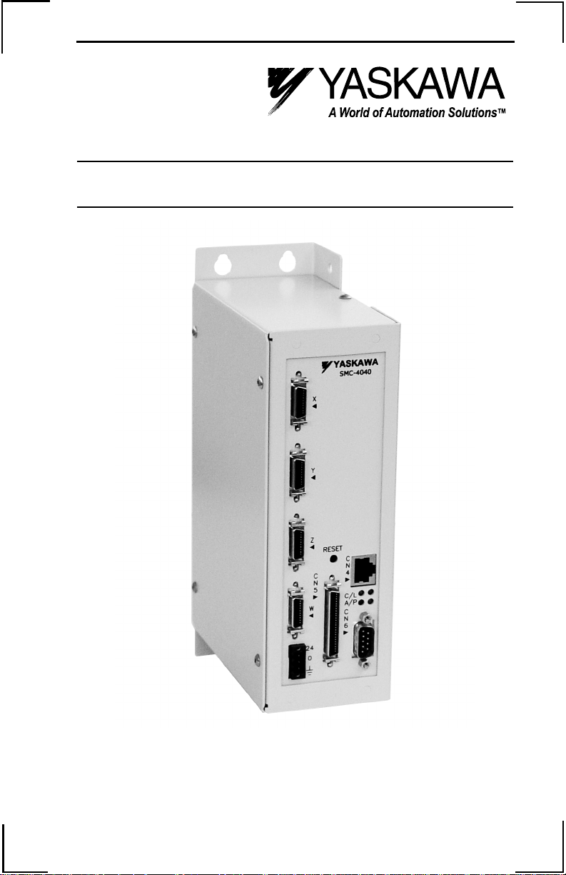
Introduction
The SMC–4000 is a multi-axis Ethernet motion controller
designed for use with Yaskawa’s SIGMA series and
LEGEND Digital Torque Amplifier.
It provides a structured text programming environment
and the ability to perform many modes of motion
including camming, gearing, and contouring. High
speed product registration is also available as a standard
feature.
Additionally, the Ethernet function allows multiple
devices to communicate with the controller using a
TELNET or MODBUS protocol.
1
Page 6
SMC–4000 Installation Guide
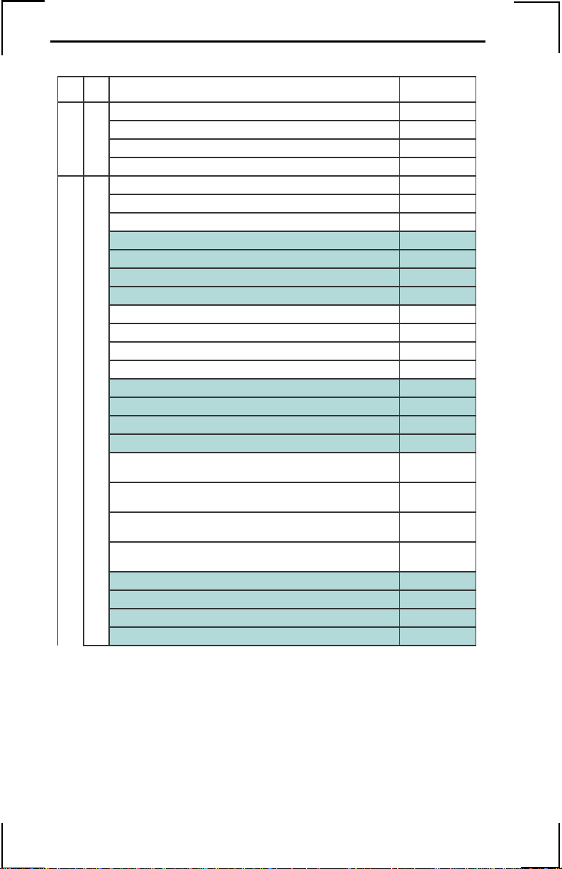
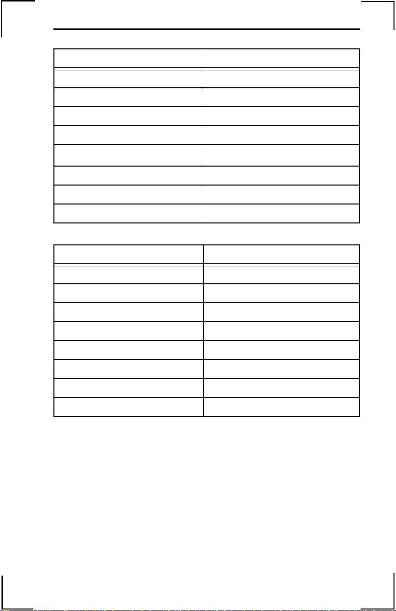
Part Numbers
Description Part Number
a) Two axis motion controller SMC4020
Two axis motion controller w/ absolute encoder option SMC4020W
Four axis motion controller SMC4040
Controller
Four axis motion controller w/ absolute encoder option SMC4040W
b) Pigtail (5 feet) SMCCBL005
Pigtail (10 feet) SMCCBL010
Pigtail (15 feet) SMCCBL015
Prewired for SGD, SGDA, or SGDG (2 feet) SMCCBL102
Prewired for SGD, SGDA, or SGDG (5 feet) SMCCBL105
Prewired for SGD, SGDA, or SGDG (10 feet) SMCCBL110
Prewired for SGD, SGDA, or SGDG (15 feet) SMCCBL115
Prewired for SGDB or SGDH (2 feet) SMCCBL202
Prewired for SGDB or SGDH (5 feet) SMCCBL205
Prewired for SGDB or SGDH (10 feet) SMCCBL210
Prewired for SGDB or SGDH (15 feet) SMCCBL215
Prewired for SGDB or SGDH (2 feet) Includes Alarm & Reset SMCCBLH02
Prewired for SGDB or SGDH (5 feet) Includes Alarm & Reset SMCCBLH05
Prewired for SGDB or SGDH (10 feet) Includes Alarm & Reset SMCCBLH10
Prewired for SGDB or SGDH (15 feet) Includes Alarm & Reset SMCCBLH15
Encoder Cables
Prewired for SGD, SGDA, or SGDG (2 feet) with additional
pigtail
Prewired for SGD, SGDA, or SGDG (5 feet) with additional
pigtail
Prewired for SGD, SGDA, or SGDG (10 feet) with additional
pigtail
Prewired for SGD, SGDA, or SGDG (15 feet) with additional
pigtail
Prewired for SGDB or SGDH (2 feet) with additional pigtail SMCCBLB02
Prewired for SGDB or SGDH (5 feet) with additional pigtail SMCCBLB05
Prewired for SGDB or SGDH (10 feet) with additional pigtail SMCCBLB10
Prewired for SGDB or SGDH (15 feet) with additional pigtail SMCCBLB15
SMCCBLA02
SMCCBLA05
SMCCBLA10
SMCCBLA15
2
Page 7

SMC–4000 Installation Guide
Description Part Number
c) 1.0m pigtail cable JZSP-CKIO1-
2.0m pigtail cable JZSP-CKIO1-
3.0m pigtail cable JZSP-CKIO1-
1.0m cable with OMRON terminal block JUSP TA50P
I/O
0.5m 50 pin I/O cable to DSUB JZSP-CKIOD-
1.0m 50 pin I/O cable to DSUB JZSP-CKIOD-
2.0m 50 pin I/O cable to DSUB JZSP-CKIOD-
CN5 Connector Kit (same as SGDH 1CN kit) JZSP-CKI9
d) 2.0m CN6 serial port cable (included with YTerm software) SMCCBL7
Serial
e) YTerm Integrated Development Environment SMCGUI1
1(A)
2(A)
3(A)
D50
01
02
SMCComm serial & ethernet driver for application development
for all SMC products
Software
f) Replacement power supply connector UFS-0118
SMCOCX1
Other
3
Page 8
SMC–4000 Installation Guide
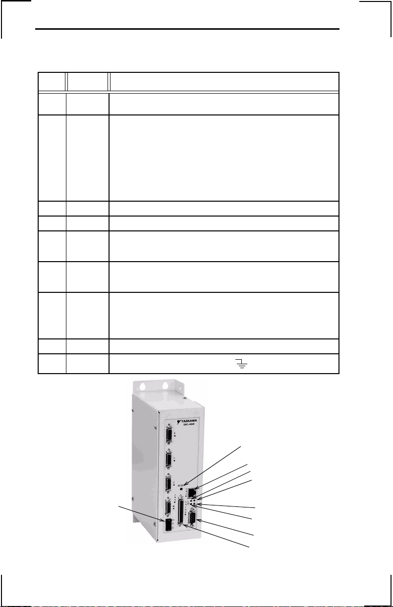
Start-up
Front Panel Descriptio
No. Name Description
(1) Power
ON
(2) Alarm/
Error
(3) CN6 9 pin male D-Sub serial port connector
(4) CN5 3M 50 pin high density I/O connector
(5) RST Reset button. Causes the controller to reboot, and load the application
(6) Ethernet
status
(7) Ethernet
status
(8) CN4 10 BaseT Ethernet RJ45 Connector
(9)
A green LED that indicates power is being applied to the SMC–4000.
A red LED that will flash ON at power up and stay lit for ap proximately 2
seconds. After power up, the LED will illuminate for the following
reasons:
• An axis has a position error greater than the error limit. The error
limit is set by using the ER command.
• The reset input on the controller is held low or is being affected by
noise.
• There is a failure in the controller and the processor is resetting
itself.
• There is a failure in the output IC which drives the error signal.
program and parameters from flash. If the pro gram contains an #A UTO
label, it will automatically execute.
A green LED that is lit when there is an Ethernet connection to the
controller. This LED indicates physical connection, not active
communication.
The yellow LED indicates traffic across the Ethernet connection. This
LED will show both transmit and receive activity across the connection.
If there is no Ethernet connection or IP address assigned, the LED will
flash at regular intervals to show that the BOOTP packets are being
broadcast.
Power Connector (+24VDC, 0VDC, FG
(5)
(8)
(7)
(6)
(9)
(1)
(2)
(3)
(4)
4
Page 9

SMC–4000 Installation Guide
Axis Connector (20–pin)
SMC Axis Connector SGDH CN1
PIN SIGNAL Reference Pin
1 PA input 33
2 /PA input 34
3 PB input 35
4 /PB input 36
5 PC input 19
6 /PC input 20
7 Motor Command output 9
8 +5 / +12 / -12 Common output 10
9 +5 / +12 / -12 Common output 2
10 +5 / +12 / -12 Common output 6
11 Amplifier Enable output 40
12 Step output 11
13 Sen/Dir output 4
14 +5 / +12 / -12 Common output 1
15 Alarm + input 31
16 Reset output 44
17 ALM - input 32
18 n/c
19 +24 VDC output 47
20 n/c
5
Page 10

SMC–4000 Installation Guide
I/O Connections (50-pin CN5)
SMC Output Connector CN5 SMC Output Connector CN5
PIN
(Numerical Order)
1 Home W Abort 33
2 Home Z E-Stop1 39
3 Home Y E-Stop2 40
4 Home X Forward Limit W 27
5 Input 1 Forward Limit X 30
6 Input 4 Forward Limit Y 29
7 Input 7 Forward Limit Z 28
8 Output 3 Home W 1
9 Output 5 Home X 4
10 Output 8 Home Y 3
11 X Aux Encoder A+ Home Z 2
12 X Aux Encoder B- Input 1 5
13 Y Aux Encoder B+ Input 2 18
14 Reverse Limit W Input 3 31
15 Reverse Limit Z Input 4 6
16 Reverse Limit Y Input 5 19
17 Reverse Limit X Input 6 32
18 Input 2 Input 7 7
19 Input 5 Input 8 20
20 Input 8 Output 1 34
21 Output 2 Output 2 21
22 Output 7 Output 3 8
23 X Aux Encoder A- Output 4 35
24 Y Aux Encoder A+ Output 5 9
25 Y Aux Encoder B- Output 6 36
26 Reset Output 7 22
27 Forward Limit W Output 8 10
28 Forward Limit Z Reset 26
29 Forward Limit Y Reverse Limit W 14
30 Forward Limit X Reverse Limit X 17
31 Input 3 Reverse Limit Y 16
32 Input 6 Reverse Limit Z 15
33 Abort Spare 1 49
34 Output 1 Spare 2 50
35 Output 4 W Aux Encoder A- 46
36 Output 6 W Aux Encoder A+ 45
37 X Aux Encoder B+ W Aux Encoder B- 48
38 Y Aux Encoder A- W Aux Encoder B+ 47
39 E-Stop1 X Aux Encoder A- 23
6
SIGNAL
SIGNAL
(Alphabetical Order)
PIN
Page 11

SMC–4000 Installation Guide
SMC Output Connector CN5 SMC Output Connector CN5
PIN
(Numerical Order)
40 E-Stop2 X Aux Encoder A+ 11
41 Z Aux Encoder A+ X Aux Encoder B- 12
42 Z Aux Encoder A- X Aux Encoder B+ 37
43 Z Aux Encoder B+ Y Aux Encoder A- 38
44 Z Aux Encoder B- Y Aux Encoder A+ 24
45 W Aux Encoder A+ Y Aux Encoder B- 25
46 W Aux Encoder A- Y Aux Encoder B+ 13
47 W Aux Encoder B+ Z Aux Encoder A- 42
48 W Aux Encoder B- Z Aux Encoder A+ 41
49 Spare 1 Z Aux Encoder B- 44
50 Spare 2 Z Aux Encoder B+ 43
SIGNAL
SIGNAL
(Alphabetical Order)
PIN
7
Page 12

SMC–4000 Installation Guide
P
P
P
Cable Shielding, Segregation and Noise Immunity
Proper
Shields tied
back at device
ROPER
Shield connected ac ross
terminal block.
a)
SMC 3010
Connector
Case
Terminal Block
Connector Case
b)
Improper
Connector
a)
Connector Case
ROPER
Shield tied back a t
terminal block.
Case
WRONG
Shield grounded at
more than one point.
Terminal Block
Terminal Block
Terminal Block
Shields tied
back at device
ROPER
Shields of field
cables grounded at
one point
Shields tied
back at device
Shields tied
back at device
b)
WRONG
Shields of field
cables ungrounded
8
Page 13

SMC–4000 Installation Guide
Digital I/O
Digital Input
Item Specifications
Number of Input Points 8
Input Format Sinking
Isolation Optical
Voltage 24VDC ± 20%
Current Rating (ON) 5.3mA to activate
Input Impedance 2.2kΩ
Operation Voltage Logic 0 <5V
Logic 1 >15V
OFF Current 0.9mA or less
Response Time
(Hardware)
Latch response time Less than 25µsec
Minimum latch width 9µsec
NOTE: Inputs float high unless the input is held low.
OFF to ON: <0.5ms
ON to OFF: <1.5ms
Internal Circuitry
SMC–4000 CN5 Connector
24VDC
2.2K
5
18
31
6
19
32
7
20
Digital Input 1/Latch X
Digital Input 2/Latch Y
Digital Input 3/Latch Z
Digital Input 4/Latch W
Digital Input 5
Digital Input 6
Digital Input 7
Digital Input 8
9
Page 14

SMC–4000 Installation Guide
Digital Output
Item Specifications
Number of Output Points 8
Output Format Sinking
Output Classification Transistor Output
Isolation Optical
Load Voltage 24VDC ± 20%
Load Current 200mA/Output (600mA if activated individually)
Response Time OFF to ON <0.25ms
ON to OFF <0.5ms
External Common Power 24VDC ± 20% 15mA
Common User Fuse Rating 800mA per bank of four
Individual User Fuse Rating 200mA recommended
NOTE: The ULN 2803 output chip is capable of 600mA at a single output,
or 800mA for the eight outputs simultaneously.
Internal Circuitry
SMC–4000 CN5 Connector
Field Wiring
PS2504–4
0VDC from power input
10
10k
ULN2803
4.7k
34
Digital Output 1
Digital Output 2
21
Digital Output 3
8
Digital Output 4
35
Digital Output 5
9
Digital Output 6
36
Digital Output 7
22
10
Digital Output 8
L
L
L
L
L
L
L
L
Fuse
Page 15

SMC–4000 Installation Guide
Emergency Stop Chain
Internal Circuitry
VCC
SMC–4000 CN5 Connector
Field Wiring
-EROUT
39
40
2N7002
1k
E STOP1
E STOP2
The SMC–4000 closes the relay contact under normal operating
conditions. The relay is controlled by the same circuit as the error
LED. The relay will be open if the error LED is ON.
Ratings:
1.0A @ 24VDC
0.5A @ 125VDC
Maximum switching power: 62.5VA, 30W
11
Page 16

SMC–4000 Installation Guide
Serial Communication
Item Specifications
Baud Rate 9600 or 19200 settable by jumper JP2, default is 19200
Data Bits 8
Parity None
Stop Bits 1
Internal Circuitry
C1+
.1 UF
C1C2+
.1 UF
C2T1IN
T2IN
A1OUT
A2OUT
MAX232A
T1OUT
T2OUT
A1IN
A2IN
V+
V-
U7
SMC–4000
VCC
.1 UF
.1 UF
Serial Port 6CN
1
6
8
2
3
7
4
9
5
CTS Output
CTS Output
CTS Output
Transmit Input
Receive Input
RTS Input
RTS Input
N/C
Signal Ground
NOTE: Hardware handshaking must be used with the SMC–4000. If it
is impossible to implement hardware handshaking, use a jumper
between pins 1 and 4 in the connector.
NOTE: Do not connect pin 5 to a 24V ground. This would defeat the
opto isolation.
12
Page 17

SMC–4000 Installation Guide
External Encoder Specifications
Item Specifications
Number of External
One per Main Axis
Encoders
Input Format Quadrature or
Pulse and Direction
Maximum Frequency 12 MHz
Current Draw 940 µAmp
Internal Circuitry
3486
3486
4.7k
4.7k
6.8k
2.4k
SMC–4000
VCC
6.8k
2.4k
X axis internal encoder shown
See 5CN connector for other axis pin connections.
5CN Connector
Field Wiring
11
23
37
12
A+ phase
A- phase
B+ phase
B- phase
Shield
Frame Ground
External Encoder
+5V or +12V
Standard voltage levels are TTL (0V to 5V), however, voltage levels
up to 12V are acceptable. If using differential 12V signals, no
modification is required. Single ended 12V signals require a bias
voltage applied to the complimentary input, i.e.; use two 10k resistors,
one connected to +12V and the other connected to the encoder signal
ground to hold the /A phase and /B phase at 6VDC. Do not use a
24VDC encoder.
13
Page 18

SMC–4000 Installation Guide
Dedicated Inputs
Item Specifications
Number of Input Points Forward limit, Reverse limit, Home for all axes; and
Abort, Reset
Input Format Sinking
Isolation Optical
Voltage 24 VDC ± 20%
Current Rating (ON) 5.3 mA to activate
Input Impedance 2.2k Ω
Operation Voltage Logic 0 <5V
Logic 1 >15V
OFF Current 0.9 mA or less
Limit Switch Response
Time
Internal Circuitry
X axis dedicated inputs shown. Other axes are the
same.
OFF to ON: <0.5 ms
ON to OFF: <1.5 ms
SMC–4000
+24 VDC
2.2k
CN5 Connector
Field Wiring
Forward Limit Switch
30
Reverse Limit Switch
17
4
33
26
External Input Signal
Home Input
Abort Input
Reset Input
0VDC
14
Page 19
SMC–4000 Installation Guide
Physical Specifications
Description Specifications
Depth 5 inches
Width 2.6 inches
Height 9.1 inches
Weight 3.52lbs (1.6kg)
Vibration
Ambient Temperature 0 ~ 70° C (32 ~ 158° F)
Humidity Less than 95%
Noise IEC Level 3
9.8 msec
2
(1.0g)
Hardware Specifications
Description Specifications
CPU 25MHz Motorola
Servo Update 1000µs default, 250µs minimum
Digital Inputs (8), +24VDC
Dedicated Inputs (2) +24VDC +3 per axis @24VDC
Digital Outputs (8), +24VDC
Serial port (1) 9600 or 19200 baud
Ethernet (1) 10-base-T
Power Input 24 VDC – 600mA
15
Page 20

SMC–4000 Installation Guide
Dimensional Drawings
16
Page 21

SMC–4000 Installation Guide
I/O Cable with Terminal Block JUSP-TA50P
CN5
Length of cable supplied: 19.69 (500)
50-pin connector plug
MR-50RMD2
50-pin terminal block
M3.5 screws
+10%
-0%
1
2
9.74 (247.5)
49
50
Connector Terminal Block Converter Unit
JUSP-TA50P* (cable included)
Mounting Hole Diagram
10.01 (254.2)
0.14 (3.5)0.14 (3.5)
0.61 (15.5)
0.27 (7.0)
* Terminal specifications: see I/O Connections (50-pin CN5), page 6.
10.28 (261.2)
0.27 (7.0)
1.16
1.77 (45)
(29.5)
1.77 (45)
17
Page 22

SMC–4000 Installation Guide
NOTES
18
Page 23

SMC–4000 Installation Guide
Page 24

SMC–4000 Installation Guide
YASKAWA ELECTRIC AMERICA, INC.
Chicago-Corporate Headquarters 2121 Norman Drive South, Waukegan, IL 60085, U.S.A.
Phone: (847) 887-7000 Fax: (847) 887-7310 Internet: http://www.yaskawa.com
MOTOMAN INC.
805 Liberty Lane, West Carrollton, OH 45449, U.S.A.
Phone: (937) 847-6200 Fax: (937) 847-6277 Internet: http://www.motoman.com
YASKAWA ELECT R IC CORPORATION
New Pier Takeshiba South Tower, 1-16-1, Kaigan, Minatoku, Tokyo, 105-0022, Japan
Phone: 81-3-5402-4511 Fax: 81-3-5402-4580 Internet: http://www.yaskawa.co.jp
YASKAWA ELETRICO DO BRASIL COMERCIO LTDA.
Avenida Fagundes Filho, 620 Bairro Saude Sao Paolo-SP, Brasil CEP: 04304-000
Phone: 55-11-5071-2552 Fax: 55-11-5581-8795 Internet: http://www.yaskawa.com.br
YASKAWA ELECT R IC EU ROPE GmbH
Am Kronberger Hang 2, 65824 Schwalbach, Germany
Phone: 49-6196-569-300 Fax: 49-6196-888-301 Internet: http://www.yaskawa.de
MOTOMAN ROBOTICS AB
Box 504 S38525, Torsas, Sweden
Phone: 46-486-48800 Fax: 46-486-41410
MOTOMAN ROBOTEC GmbH
Kammerfeldstrabe 1, 85391 Allershausen, Germany
Phone: 49-8166-900 Fax: 49-8166-9039
YASKAWA ELECTRIC UK LTD.
1 Hunt Hill Orchardton Woods Cumbernauld, G68 9LF, Scotland, United Kingdom
Phone: 44-12-3673-5000 Fax: 44-12-3645-8182
YASKAWA ELECTRIC KOREA CORPORATION
Paik Nam Bldg. 901 188-3, 1-Ga Euljiro, Joong-Gu, Seoul, Korea
Phone: 82-2-776-7844 Fax: 82-2-753-2639
YASKAWA ELECTRIC (SINGAPORE) PTE. LTD.
Head Office: 151 Lorong Chuan, #04-01, New Tech Park Singapore 556741, SINGAPORE
Phone: 65-282-3003 Fax: 65-289-3003
TAIPEI OFFICE (AND YATEC ENGINEERING CORPORATION)
10F 146 Sung Chiang Road, Taipei, Taiwan
Phone: 886-2-2563-0010 Fax: 886-2-2567-4677
YASKAWA JASON (HK) COMPANY LIMITED
Rm. 2909-10, Hong Kong Plaza, 186-191 Connaught Road West, Hong Kong
Phone: 852-2803-2385 Fax: 852-2547-5773
BEIJING OFFICE
Room No. 301 Office Building of Beijing International Club,
21 Jianguomanwai Avenue, Beijing 100020, China
Phone: 86-10-6532-1850 Fax: 86-10-6532-1851
SHANGHAI OFFICE
27 Hui He Road Shanghai 200437 China
Phone: 86-21-6553-6600 Fax: 86-21-6531-4242
SHANGHAI YASKAWA-TONJI M & E CO., LTD.
27 Hui He Road Shanghai 200437 China
Phone: 86-21-6533-2828 Fax: 86-21-6553-6677
BEIJING YASKAWA BEIKE AUTOMATION ENGINEERING CO., LTD.
30 Xue Yuan Road, Haidian, Beijing 100083 China
Phone: 86-10-6232-9943 Fax: 86-10-6234-5002
SHOUGANG MOTOMAN ROBOT CO., LTD.
7, Yongchang-North Street, Beijing Economic & Technological Development Area,
Beijing 100076 China
Phone: 86-10-6788-0551 Fax: 86-10-6788-2878
YEA, TAICHUNG OFFICE IN TAIWAN
B1, 6F, No. 51, Section 2, Kung-Yi Road, Taichung City, Taiwan, R.O.C.Phone: 886-4-2320-2227 Fax: 886-4-23202239
Phone: 55-11-5071-2552 Fax: 55-11-5581-8795 Internet: http://www.yaskawa.com.br
Yaskawa Electric America, Inc., January 2004 YEA–TOA–SMC–4.3 Printed in U.S.A.
 Loading...