

Page 1
SMC-2000 Multi-Axis Motion Controller
User’s Guide Version 3.1
Page 2

Overview
Introduction
The SMC-2000 Series are packaged motion controllers designed for stand-alone operation. Features include
coordinated motion profiling, uncommitted inputs and outputs, non-volatile memory for stand-alone operation
and RS232/RS422 communication. Extended performance capability includes: fast 8 MHz encoder input
frequency, precise 16-bit motor command output DAC, +/-2 billion counts total travel per move, faster sample
rate, and multitasking of up to four programs. The controllers provide increased performance and flexibility
featuring plug and play operation.
Designed for maximum system flexibility, the SMC-2000 is available in one, two, four, and eight axes
configurations.
Each axis accepts feedback from a quadrature linear or rotary encoder with input frequencies up to 8 million
quadrature counts per second. For dual-loop applications that require one encoder on both the motor and the
load, auxiliary encoder inputs are included for each axis.
The powerful controller provides several modes of motion including jogging, point-to-point positioning, linear
and circular interpolation with infinite vector feed, electronic gearing and user-defined path following. Several
motion parameters can be specified including acceleration and deceleration rates, and slew speed. To eliminate
jerk, the SMC-2000 provides S-curve profiling.
For synchronizing motion with external events, the SMC-2000 includes 8 optically isolated inputs, eight
programmable outputs and seven analog inputs (eight optional). I/O expansion boards provide additional inputs
and outputs. Event triggers can automatically check for elapsed time, distance and motion complete.
Despite its full range of sophisticated features, the SMC-2000 is easy to program. Instructions are represented
by two letter commands such as BG for Begin and SP for Speed. Conditional Instructions, Jump Statements,
and arithmetic functions are included for writing self-contained applications programs.
To prevent system damage during machine operation, the SMC-2000 provides several error handling features.
These include software and hardware limits, automatic shut-off on excessive error, abort input, and
user-definable error and limit routines.
SMC-2000 User's Guide Overview
1
••••
Page 3
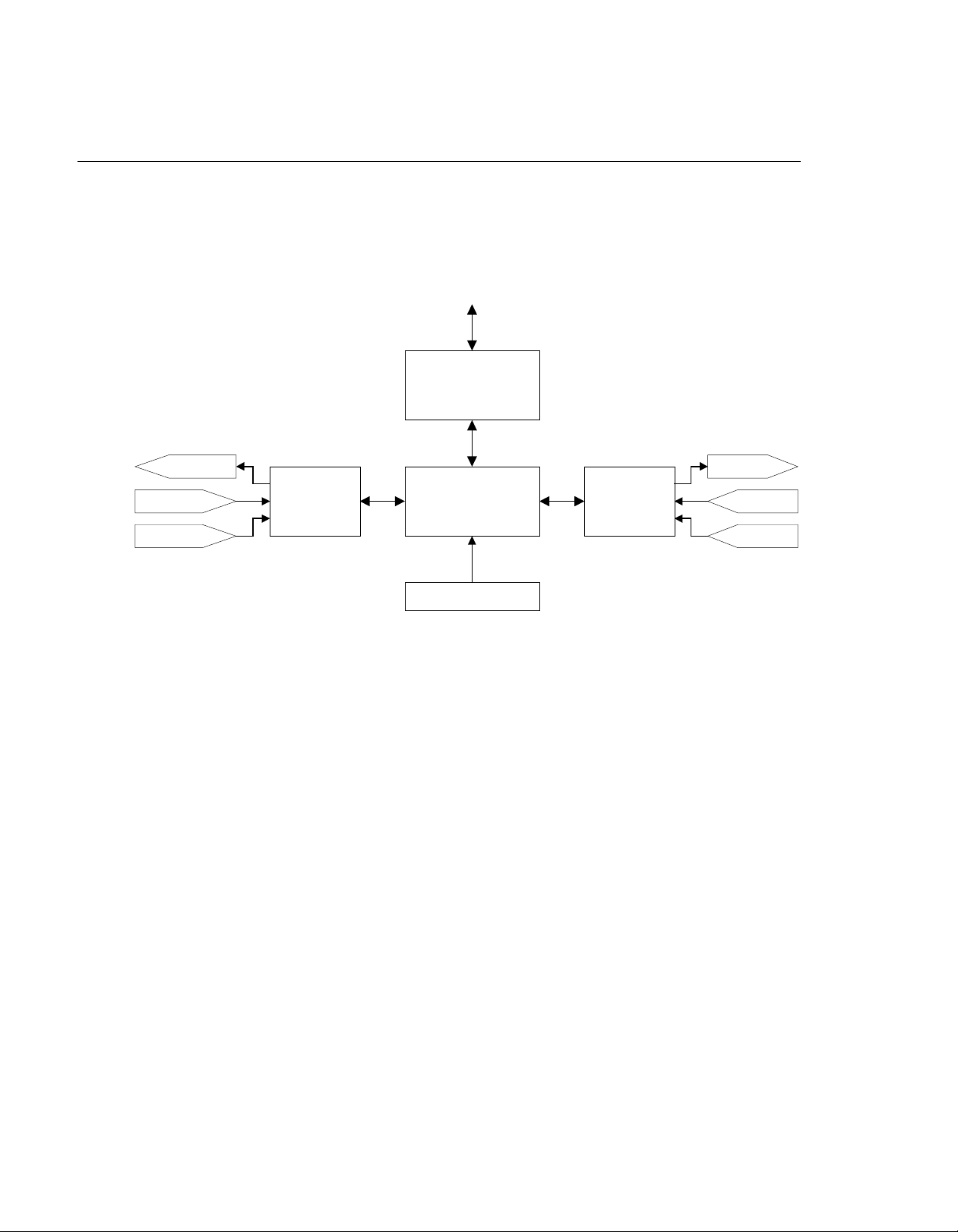
SMC-2000 Functional Elements
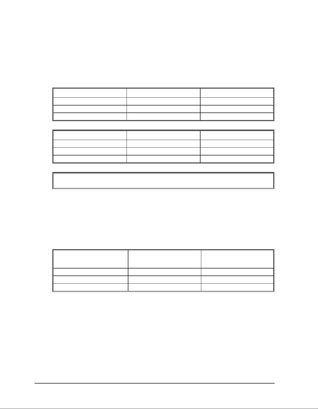
The SMC-2000 circuitry can be divided into the following functional groups as shown in Figure 1.1 and
discussed below.
To Host
RS-232 / RS-422 Serial
Communication FIFO
80 Bytes
8 24V Out
8 Digital In
8 Analog In
I/O
Interface
68340
Microcomputer
1024K RAM
256K EPROM
1024 EEPROM
Watch Dog
Timer
4-Axes
Motor/Encoder
Inte rface
To Amps
From
Limits
From
Encoders
Figure 1.1 - SMC-2000 Functional Elements
Microcomputer Section
The main processing unit of the SMC-2000 is a specialized 32-bit Motorola 68340 Series Microcomputer with
256K RAM, 64 K EPROM and 128 K bytes EEPROM. The RAM provides memory for variables, array
elements, and application programs. The EPROM stores the firmware of the SMC-2000. The EEPROM allows
parameters and programs to be saved in non-volatile memory upon power down.
Motor Interface
For each axis, a sub-micron gate array performs quadrature decoding of the encoders at up to 8 MHz, generates
the +/-10 Volt analog signal (16-Bit D-to-A) for input to a servo amplifier. Interface to hardware limits and
home inputs is also included.
Communication
Communication to the SMC-2000 is via two separately addressable RS232 ports. The factory may also
configure the ports for RS422. The serial ports may be daisy-chained to other SMC-2000 controllers.
General I/O
The SMC-2000 provides interface circuitry for eight opto-isolated inputs, eight general outputs, and seven (or
eight) analog inputs (14-Bit ADC). The eight axis SMC-2000 provides 24 inputs and 16 outputs. Additional
I/O is optional.
Page 4
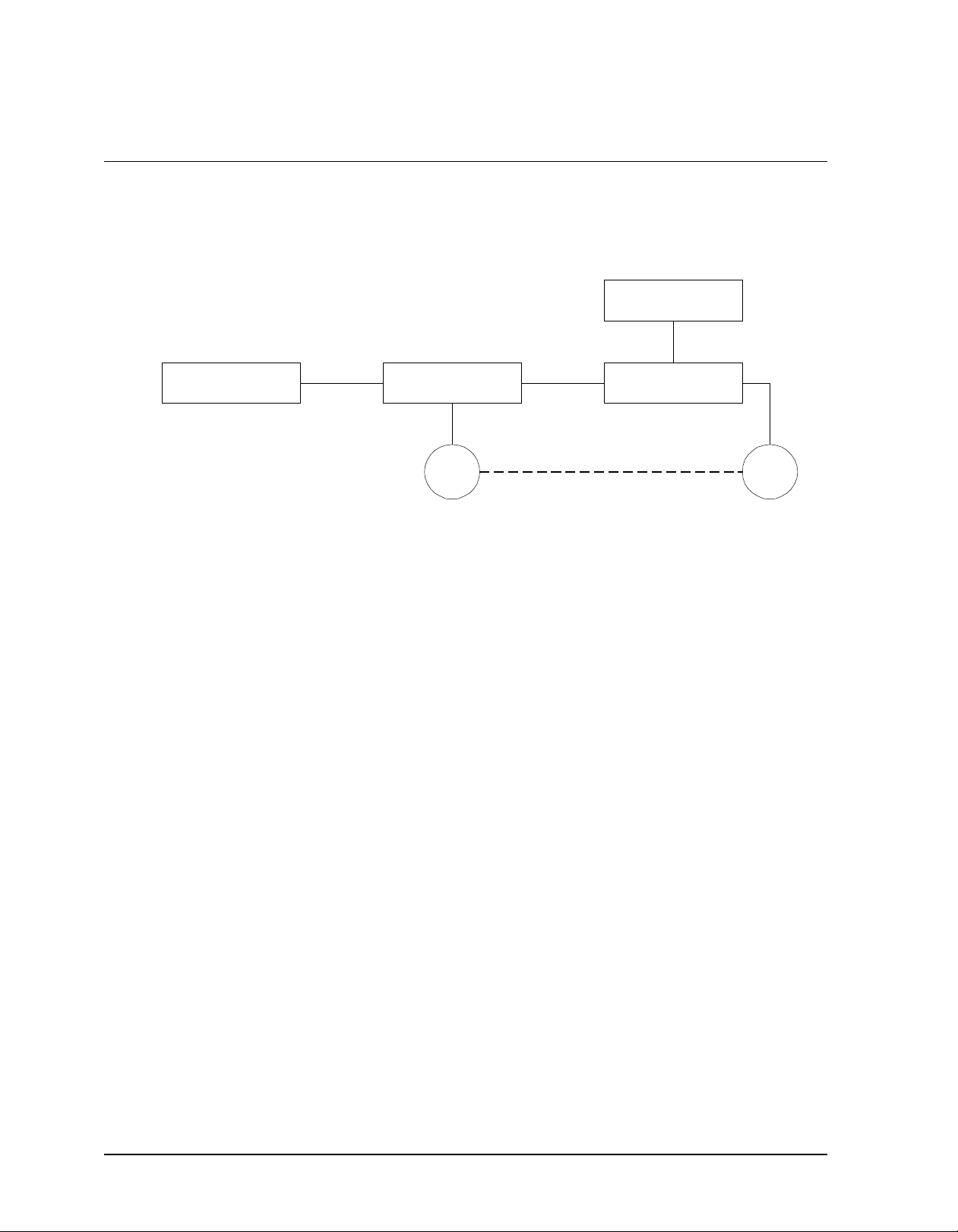
System Elements
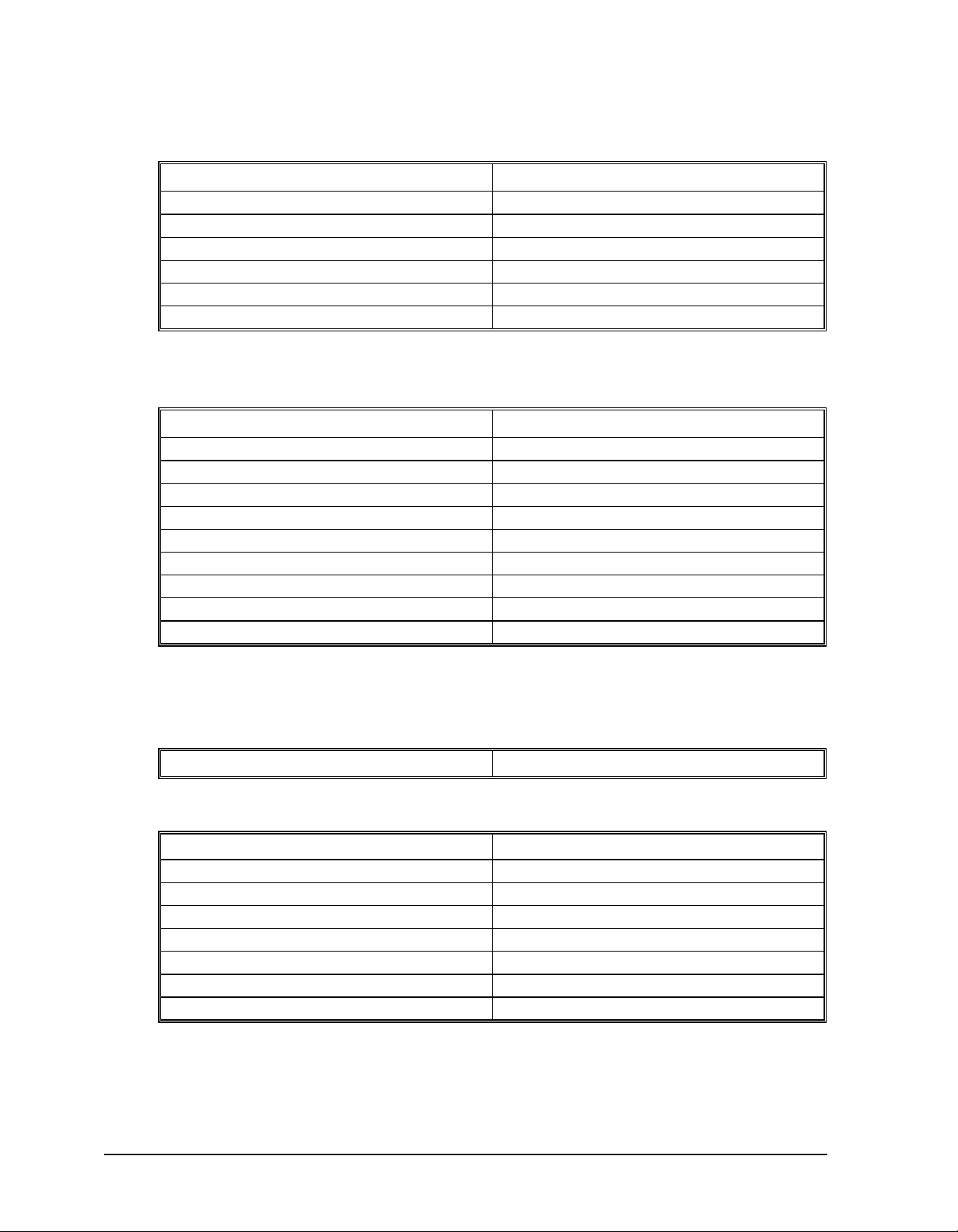
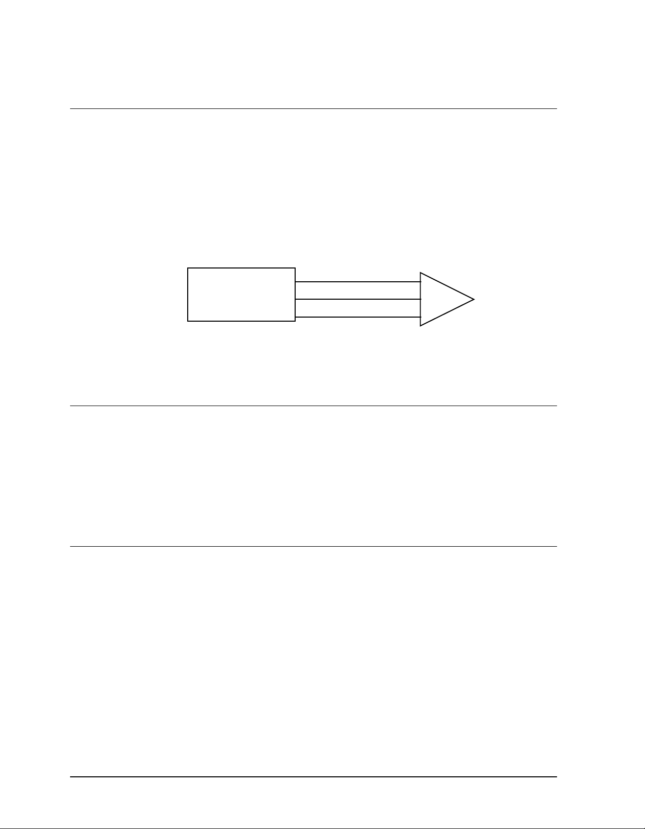
As shown in Fig. 1.2, the SMC-2000 is part of a motion control system that includes amplifiers, motors, and
encoders. These elements are described below
Computer SMC-2000 Controller Driver
Figure 1.2 - Elements of Servo systems
Motor
A motor converts current into torque, which produces motion. Each axis of motion requires a motor sized
properly to move the load at the required speed and acceleration. (Yaskawa's "YSize" software can help you
with motor sizing).
Power Supply
Encoder Motor
The servo motor and can be brush-type or brushless, rotary or linear. Please refer to Yaskawa catalogs for more
information.
Amplifier
For each axis, the power amplifier converts the +/-10 Volt signal from the controller into enough current to drive
the motor. As such, the amplifier should be sized properly to meet the power requirements of the motor. For
brushless motors, an amplifier that provides electronic commutation is required. The amplifier should be set up
to operate in a torque control mode. Set the torque reference gain so that 10 Volts at the torque reference input
will allow the amplifier/motor to operate at peak torque (typically 200-300% of rated torque). See Yaskawa
technical manuals for specifications. Please call Yaskawa if you need help configuring your amplifier.
Encoder
An encoder translates motion into an electrical signal to be fed back into the controller. The SMC-2000 accepts
feedback from either a rotary or linear encoder. The preferred encoder is the one with two channels in
quadrature, CHA and CHB. This encoder may also have a third channel (or index) for synchronization. When
necessary, the SMC-2000 can interface to encoders with pulse and direction signals.
There is no limit on encoder line density, however, the input frequency to the controller must not exceed
2,000,000 full encoder cycles/second (8,000,000 quadrature counts/sec). For example, if the encoder line
density is 10000 cycles per inch, the maximum speed is 200 inches/second.
The encoder type may be either single-ended (CHA and CHB) or differential (CHA,CHA-,CHB,CHB-). The
SMC-2000 decodes either type into quadrature states or four times the number of cycles.
SMC-2000 User's Guide Overview
3
••••
Page 5

The standard voltage level is TTL (zero to five volts), however, voltage levels up to 12 Volts are acceptable. (If
using differential signals, 12 Volts can be input directly to the SMC-2000. Single-ended 12 Volt signals require
a bias voltage input to the complementary inputs)
Page 6

SMC-2000 User's Guide Overview
1
••••
Page 7

Getting Started
Elements You Need
Before you start, you must get all the necessary system elements. These include:
1. SMC-2000 Series Controller
2. Servo motors and amplifiers
3. 24 Volt Class 2 Power Supply for SMC-2000 and Amplifiers
4. PC (Personal Computer with RS232 port) with at least 4MB of RAM and Windows 3.1 or higher.
5. Communication Disk (YTerm-2000 software) from Yaskawa
6. All interface and communication cables
Warning: Follow the “Tuning Servo System” procedure before applying power to the SMC
unit and the servo amplifier at the same time. Applying power to the SMC unit and the
amplifiers at the same time may result in damage to the mechanical system if the initial gain
parameters for the SMC unit are not properly set.
Installing the SMC-2000
Connecting AC and DC Power to the Controller
The SMC-2000 requires a single AC supply voltage, single phase, 50 Hz or 60 Hz, from 85 volts to 264 volts,
and a +24 (±10%) Volt Class 2 DC supply for I/O. It is also recommended that AC and DC wiring is kept
separate in order to avoid noise and interference.
Warning: Do NOT use the I/O 24 VDC power supply to power any holding brakes that may
be connected to your servo motors. Use a dedicated supply for that purpose.
Warning
associated amplifier(s) and servo motor(s). Extreme caution should be exercised in the application of this
equipment. Only qualified individuals should attempt to install, set up and operate this equipment.
SMC-2000 User's Guide Getting Started
: Dangerous voltages, current, temperatures and energy levels exist in this product and in its
1
••••
Page 8
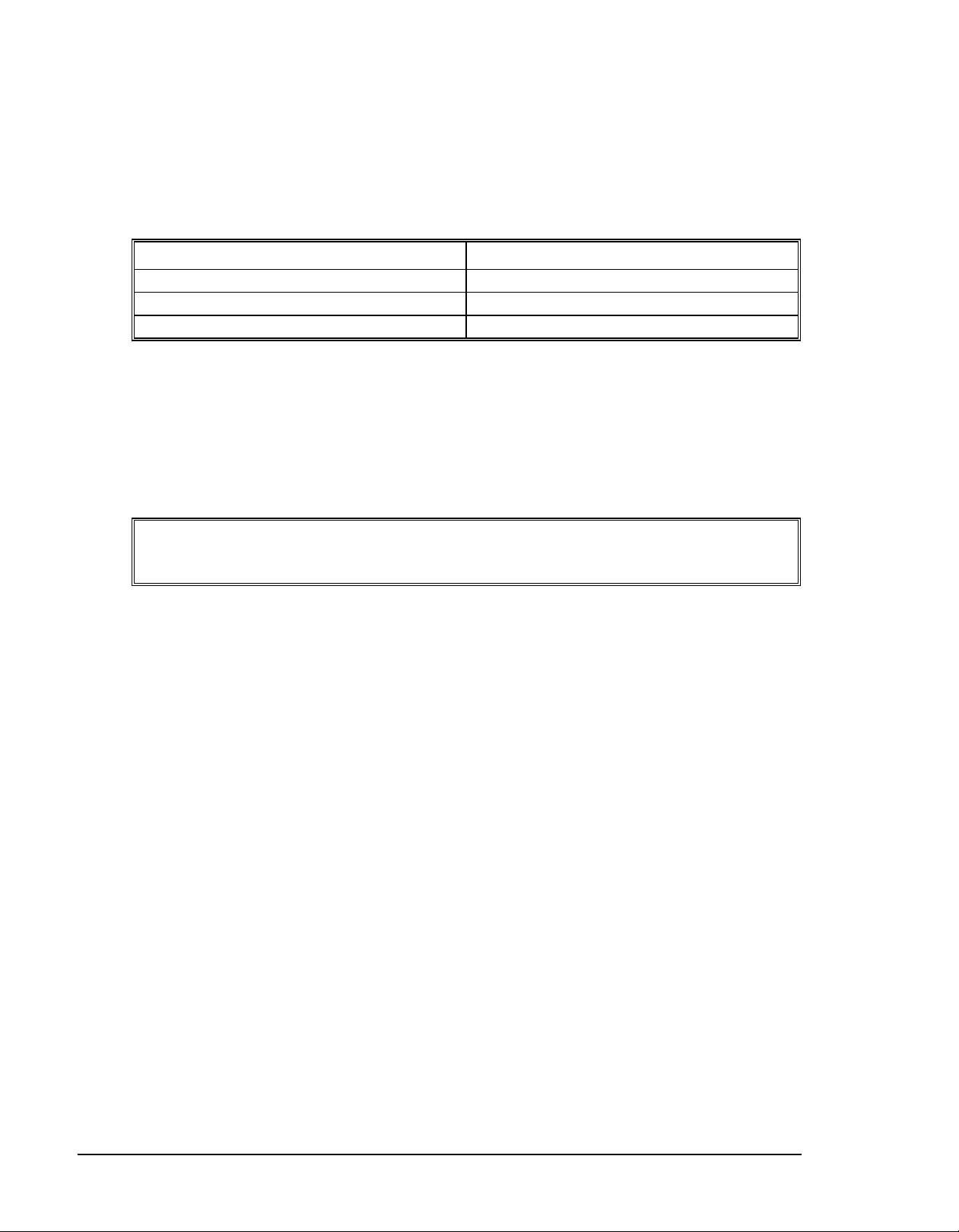
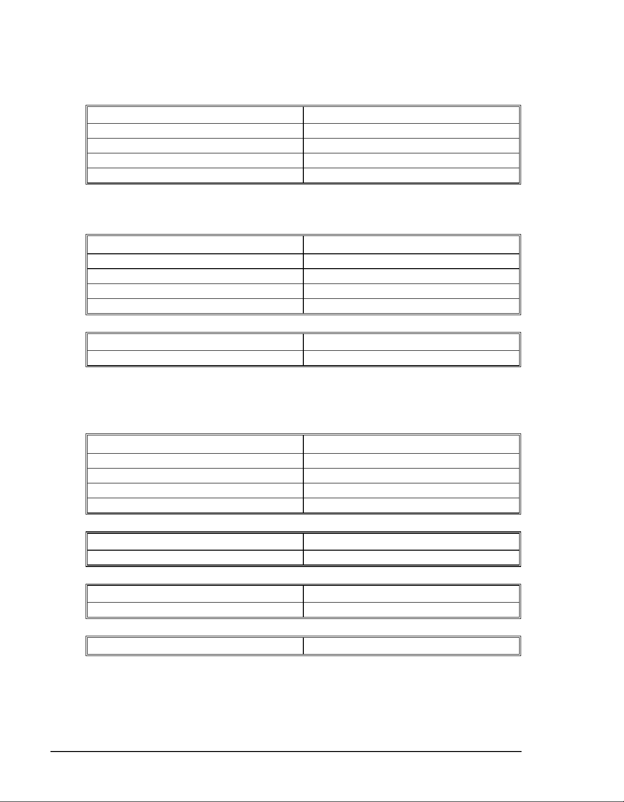
The AC and DC power is applied to the power connector at the bottom of the front panel. The power connector
is a 6-pin black screw-type terminal. Note that the AC power is applied to the LEFT side while the DC power is
applied to the RIGHT. The five connections are:
Pin Connect to:
GND Earth Ground
N & L AC In, 85V - 264V
0 & 24V 24 Volt DC and Common
Warning
Applying AC power will turn on the green light power indicator.
: Never open the controller box when AC power is applied to it.
Connecting Servo Motors and the Amplifiers
Before connecting the amplifier to the controller, you need to verify that the ground level of the amplifier is
either floating or at the same potential as earth.
WARNING: When the amplifier ground is not isolated from the power line or when it has a
different potential than that of the computer ground serious damage will result to the
computer controller and amplifier.
If you are not sure about the potential of the ground levels, connect the two ground signals by a 10 KΩ resistor
and measure the voltage across the resistor. Only if the voltage is zero, proceed to connect the two ground
signals directly.
Establishing Communication - RS232
Use the 9-Pin RS232 cable to connect the MAIN (Com 1) SMC-2000 serial port to your computer Com port.
Your computer must be configured for a baud rate setting of 19.2 KB, full duplex, no parity, 8 bits data, one
start bit, and one stop bit. The Yaskawa software “YTerm-2000” will accomplish this configuration.
At this point you should install YTerm-2000 software. This software requires the use of Windows 3.1 or above,
and at least 4M of RAM. The YTerm-2000 communication disk from Yaskawa provides a terminal emulator /
configuration program for your computer. Follow the steps below to install and run the terminal emulator.
Installation
:
1. Insert Disk in drive A: ( or B)
2. From Windows Program Manager or Start Menu, select <Run> command.
3. Run: A:\Setup ( or B:\Setup)
4. After the Yaskawa group is created, make sure the SMC-2000 has AC power connected to it then
double-click the YTerm-2000 icon to start the program.
Encoder Interface
Encoder interface is part of the Yaskawa supplied cable that connects the SMC with the Yaskawa amplifier.
See the pinout for connector AE1 or AE2 for Auxiliary Encoder interface connection, found in the appendix.
2
Getting Started SMC-2000 User's Guide
••••
Page 9
Tuning Servo System
Step 1. Setting servo(s) parameters
Yaskawa servo amplifier models SGD, SGDA, SGDB need to be set up to operate in a Torque Mode.
Parameter ( SGD, SGDA ) Function Setting
Cn-01, bit B , A Torque Control Mode Selection 1,0
Cn-13 Torque Reference Gain 30
Cn-01, bit 2,3 Limit Switch Disable 1,1
Parameter ( SGDB ) Function Setting
Cn-2B Torque Control Mode Selection 2
Cn-13 Torque Reference Gain 30
Cn-01, bit 2,3 Limit Switch Disable 1,1
NOTE: When using a motor with an absolute encoder please see the Absolute Encoder
section in chapter 12 for additional parameter settings.
Step 2. Applying Power to SMC unit and servos
Apply power to SMC-2000. Input the command MO (CR), this will shut off control of the SMC to the servo(s).
Apply power to the servo amplifier.
Step 3. Setting Gain values in SMC unit
Set gains to default values:
Command Function Default value for
SG** servo
KD Derivative Constant 10
KP Proportional Constant 1
KI Integrator 0
Step 4. Enable Servo
In order to properly tune the servo system, enable one servo at a time with the
E, F, G, H
). After enabling a servo, maximize the gains.
SH*
command (
*=X, Y, Z, W,
Step 5. Maximize Gains
For more damping, you can increase KD (maximum is 4095). Increase gradually and stop after the motor
vibrates. A vibration is noticed by the audible sound or by interrogation. If you send the command
TE X (CR) Tell error
SMC-2000 User's Guide Getting Started
3
••••
Page 10

a few times, and get varying responses, especially with reversing polarity, it indicates system vibration. When
that is the case, simply reduce KD.
Next you need to increase the value of KP gradually (maximum allowed is 1023). You can monitor the
improvement in the response with the Tell Error instruction.
KP 10 (CR) Proportion gain
TE X (CR) Tell error
As the proportional gain is increased, the error decreases.
Here again, the system may vibrate if the gain is too high. When that is the case, reduce KP. Typically, KP
should not be greater than KD/4.
Finally, increase the value of KI, start with zero value and increase it gradually. The integrator eliminates the
position error, resulting in improved accuracy. Therefore, the response to the instruction
TE X (CR)
becomes zero. As KI is increased, its effect is amplified and it may lead to vibrations. When that occurs, simply
reduce KI.
After tuning one axis, disable the servo with the MO* command (
tuning process for the remaining axes.
After each servo has been properly tuned, the values now need to be burned into the EEROM. This is done by
issuing the BN command. After the BN command has been issued the new values will remain effective.
Next, you are ready to try a few motion examples.
Motion Examples
Here are a few examples for using your controller.
Example 1- Profiled Move
Objective: Rotate the X-axis a distance of 10,000 counts at a slew speed of 20,000 counts/sec and an
acceleration and deceleration rates of 100,000 counts/s
Instruction Interpretation
PR 10000 Distance
SP 20000 Speed
DC 100000 Deceleration
AC 100000 Acceleration
BG X Start Motion
X, Y, Z, W, E, F, G, H), and repeat the
*=
2
.
In response, the motor turns and stops.
Example 2 - Multiple Axes
Objective: To move four axes independently.
4
Getting Started SMC-2000 User's Guide
••••
Page 11
Instruction Interpretation
PR 500,1000,600,-400 Distances of X,Y,Z,W
SP 10000,12000,20000,10000 Slew speeds of X,Y,Z,W
AC 100000,10000,100000,100000 Accelerations of X,Y,Z,W
DC 80000,40000,30000,50000 Decelerations of X,Y,Z,W
BG XZ Start X and Z motion
BG YW Start Y and W motion
Example 3 - Independent Moves
The motion parameters may be specified independently as illustrated below.
Instruction Interpretation
PR ,300,-600 Distances of Y and Z
SP ,2000 Slew speed of Y
DC,80000 Deceleration of Y
AC,100000 Acceleration of Y
SP ,,40000 Slew speed of Z
AC ,,100000 Acceleration of Z
DC ,,150000 Deceleration of Z
BG Z Start Z motion
BG Y Start Y motion
Example 4 - Position Interrogation
The position of all axes may be interrogated with the instruction
TP Tell position all axes
which returns all of the positions of the motors separated by commas.
Individual axis may be interrogated with the instructions:
TP X Tell position - X axis only
TP Y Tell position - Y axis only
TP Z Tell position - Z axis only
TP W Tell position - W axis only
TP E Tell position - E axis only (SMC-2000-8 only)
TP F Tell position - F axis only (SMC-2000-8 only)
TP G Tell position - G axis only (SMC-2000-8 only)
TP H Tell position - H axis only (SMC-2000-8 only)
The position error, which is the difference between the commanded position and the actual position, can be
interrogated by the instructions
SMC-2000 User's Guide Getting Started
5
••••
Page 12
TE Tell error - all axes
TE X Tell error - X axis only
TE Y Tell error - Y axis only
TE Z Tell error - Z axis only
TE W Tell error - W axis only
Example 5- Absolute Position
Objective: Command motion by specifying the absolute position.
Instruction Interpretation
DP 0,2000 Define the current positions of X,Y as 0 and 2000
PA 7000,4000 Sets the desired absolute positions
BG X Start X motion
BG Y Start Y motion
After both motions are completed, command:
PA 0,0 Move to 0,0
BG XY Start both motions
Example 6 - Velocity Control
Objective: Drive the X and Y motors at specified speeds.
Instruction Interpretation
JG 10000,-20000 Set Jog Speeds and Directions
AC 100000, 40000 Set accelerations
DC 50000,50000 Set decelerations
BG XY Start motion
after a few seconds, command:
JG -40000 New X speed and Direction
TV X Returns X speed
and then
JG ,20000 New Y speed
TV Y Returns Y speed
These cause velocity changes, including direction reversal. The motion can be stopped with the instruction
ST Stop
6
Getting Started SMC-2000 User's Guide
••••
Page 13
Example 7 - Operation under Torque Limit
The magnitude of the motor command may be limited independently by the instruction TL. The following
program illustrates that effect.
Instruction Interpretation
TL 0.2 Set output limit of X axis to 0.2 volts
JG 10000 Set X speed
BG X Start X motion
The X motor will probably not move as the output signal is not sufficient to overcome the friction. If the motion
starts, it can be stopped easily by the touch of a finger.
Increase the torque level gradually by instructions such as
TL 1.0 Increase torque limit to 1 volt.
TL 9.998 Increase torque limit to maximum, 9.998 Volts.
The maximum level of 10 volts provides the full output torque.
Example 8 - Interrogation
The values of the parameters may be interrogated. For example, the instruction
KP ? Return gain of X-axis.
returns the value of the proportional gain of the X axis. Similarly, the instruction
KP ,,? Return gain of Z-axis.
returns the value of the Z axis gain.
KP ?,?,?,? Return gains of all axes.
returns the gain values for the four axes.
The same procedure applies to other parameters such as KI, KD, FA, etc.
Example 9 - Operation in the Buffer Mode
The instructions may be buffered before execution as shown below.
PR 600000 Distance
SP 10000 Speed
WT 10000 Wait 10000 milliseconds before reading the next
instruction
BG X Start the motion
SMC-2000 User's Guide Getting Started
7
••••
Page 14
Example 10 - Motion Programs
Motion programs may be edited and stored in memory using Yaskawa’s YTerm-2000 software. They may be
executed at a later time.
#A Define label
PR 700 Distance
SP 2000 Speed
BGX Start X motion
EN End program
Now the program may be executed with the command
XQ #A Start the program running
Example 11 - Motion Programs with Loops
Motion programs may include conditional jumps as shown below.
Instruction Interpretation
#A Label
DP 0 Define current position as zero
V1=1000 Set initial value of V1
#LOOP Label for loop
PA V1 Move X motor V1 counts
BG X Start X motion
AM X After X motion is complete
WT 500 Wait 500 ms
TP X Tell position X
V1=V1+1000 Increase the value of V1
JP #LOOP,V1<10001 Repeat if V1<10001
EN End
After the above program is entered and downloaded to the SMC-2000, use the following command to run the
program:
XQ #A Execute Program #A
Example 12 - Motion Programs with Trippoints
The motion programs may include trippoints as shown below.
Instruction Interpretation
#B Label
DP 0,0 Define initial positions
PR 30000,60000 Set targets
SP 5000,5000 Set speeds
8
Getting Started SMC-2000 User's Guide
••••
Page 15

BGX Start X motion
AD 4000 Wait until X moved 4000
BGY Start Y motion
AP 6000 Wait until position X=6000
SP 2000,50000 Change speeds
AP ,50000 Wait until position Y=50000
SP ,10000 Change speed of Y
EN End program
To start the program, command:
XQ #B Execute Program #B
Example 13 - Control Variables
Objective: To show how control variables may be utilized.
Instruction Interpretation
#A;DP0 Label; Define current position as zero
PR 4000 Initial position
SP 2000 Set speed
BGX Move X
AMX Wait until move is complete
WT 500 Wait 500 ms
#B
V1 = _TPX Determine distance to zero
PR -V1/2 Command X move 1/2 the distance
BGX Start X motion
AMX After X moved
WT 500 Wait 500 ms
V1= Report the value of V1
JP #C, V1=0 Exit if position=0
JP #B Repeat otherwise
#C;EN End
To start the program, command
XQ #A Execute Program #A
This program moves X to an initial position of 1000 and returns it to zero on increments of half the distance.
Note that _TPX is an internal variable that returns the value of the X position. Internal variables may be
created by preceding a SMC-2000 instruction with an underscore, _.
Example 14 - Control Variables and Offset
Objective: Illustrate the use of variables in iterative loops and use of multiple instructions on one line.
SMC-2000 User's Guide Getting Started
9
••••
Page 16
Instruction Interpretation
#A;KI0;DP0;V1=8 Set initial values
#B;OF V1;WT 200 Set offset value
V2=_TPX;JP #C,@ABS[V2]<2;V2= Exit if error small, report position
V1=V1-1;JP #B Decrease Offset
#C;EN End
This program starts with a large offset and gradually decreases its value, resulting in decreasing error.
Example 15 - Linear Interpolation
Objective: Move X,Y,Z motors distance of 7000,3000,6000, respectively, along linear trajectory. Namely,
motors start and stop together.
Instruction Interpretation
LM XYZ Specify linear interpolation axes
LI 7000,3000,6000 Relative distances for linear interpolation
LE Linear End
VS 6000 Vector speed
VA 20000 Vector acceleration
VD 20000 Vector deceleration
BGS Start motion
Example 16 - Circular Interpolation
Objective: Move the XY axes in circular mode to form the path shown on Fig. 2.3.
Instruction Interpretation
VM XY Select XY axes for circular interpolation
VP -4000,0 Linear segment
CR 2000,270,-180 Circular segment
VP 0,4000 Linear segment
CR 2000,90,-180 Circular segment
VS 1000 Vector speed
VA 50000 Vector acceleration
VD 50000 Vector deceleration
VE End vector sequence
BGS Start motion
10
Getting Started SMC-2000 User's Guide
••••
Page 17

Y
R=2000
X
Figure 2-3 - Motion Path for Example 16
SMC-2000 User's Guide Getting Started
••••
11
Page 18

Page 19

SMC-2000 User's Guide Hardware Interface
Page 20

Hardware Interface
Cable Shielding, Segregation and Noise Immunity
Yaskawa recommends the following shielding and wiring precautions to maximize the performance of the SMC2000:
a) Signal cables (encoder, communication, I/O) should be routed away from AC power/signal wiring such
as motor power and amplifier power wiring
b) Separate metal conduit should be used for running signal and power wiring from the enclosure
c) Parallel runs of signal and power wiring should be avoided. If unavoidable, parallel runs should be in a
separate wire-way spaced at least 2 inches apart.
d) Signal and power wires should cross at right angles.
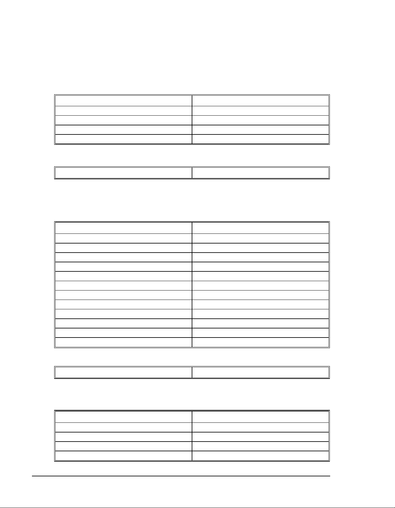
e) Shielded cables should be properly terminated by grounding the shielding conductor at one end only.
f) The shield should continue throughout the cable from device to device. The shield should be
continuous across plugs/receptacles and terminal blocks, or the shields may be grounded separately by
grounding one end and tying the shield back at the other (See Fig. 3-1a).
DO NOT
DO NOT
noise.
To improve noise immunity, all inductive loads (Brakes, Relay Coils, etc.) should have a flyback diode
connected across them to absorb and back EMF produced by that load. The flyback diode should be placed as
close to the load as possible (See Fig. 3.2a).
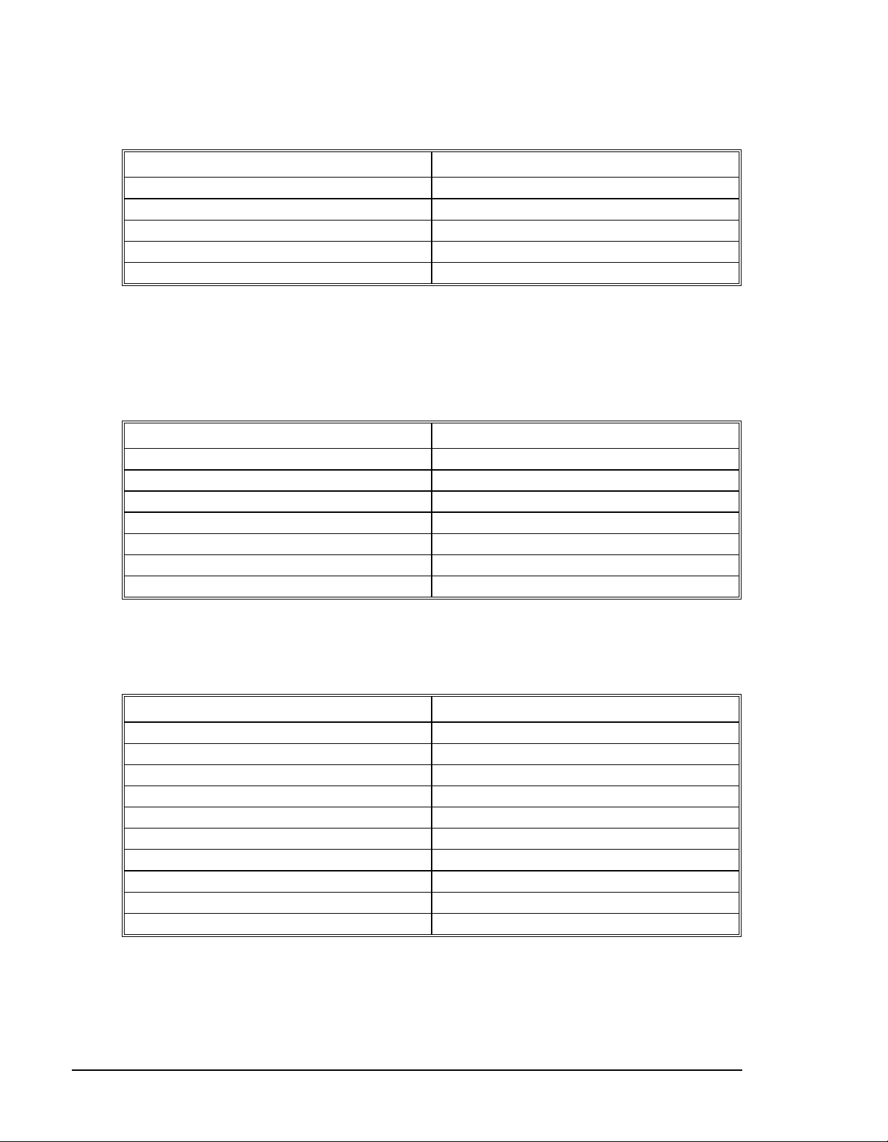
ground shields at both ends as this can create ground loops (See Fig. 3-2a).
allow the shield to remain ungrounded, this causes the shield to actually pick up and transmit
1
••••
Page 21
Proper Shield Terminations
I
P
P
P
I
r
SMC 2000 D1 or I/O
Connector
Case
Terminal Block
a)
SMC 2000 D1 or
/O Connector
Case
Terminal Block
b)
ROPER
Shield t ied back at
terminal block.
Figure 3-1 – Proper shield terminations
Improper Shield Terminations
Shields tied
back at device
ROPER
Shield connected across
terminal block.
Shields tied
back at device
ROPER
Sh i el ds o f f i e ld
cables grounded at
one point
SMC 2000 D1 or I/O
Connector
Case
a)
WR O NG
Shield grounded at
more th an one point.
SMC 2000 D1 or
/O Connecto
Case
b)
Figure 3-2 – Improper shield terminations
Termina l Block
Termina l Block
Shields tied
back at device
Shields tied
back at device
WR O NG
Sh i e l d s o f fi e ld
cables ungrounded
2
Hardware Interface SMC-2000 User's Guide
••••
Page 22

Encoder Interface
For each axis of motion, the SMC-2000 accepts inputs from incremental encoders with two channels in
quadrature, or 90 electrical degrees out of phase. The SMC-2000 performs quadrature decoding of the two
signals, resulting in bi-directional position information with a resolution of four times the number of full encoder
cycles. For example, a 500 cycle encoder is decoded into 2000 quadrature counts per revolution. An optional
third channel or index pulse may be used for homing or synchronization. Several types of incremental encoders
may be used: linear or rotary, analog or digital, single-ended or differential. Any line resolution may be used,
the only limitation being that the encoder input frequency must not exceed 2,000,000 full cycles/sec (or
8,000,000 quadrature counts/sec). The SMC-2000 also accepts inputs from an additional encoder for each axis.
These are called auxiliary encoders and can be used for dual-loop applications.
The encoder inputs are not isolated
Connections for the various types of encoders are described below.
Pin # of X, Y, ... Signal
1 Channel B
2 Channel B complementary
3 Channel A
4 Channel A complementary
5 Index
6 Index complementary
Use the above table to connect the signals as needed. For example, when connecting an encoder with Channels
A, B single ended, use pins 1 and 3, and ignore 2 and 4-6.
In a similar manner, the auxiliary encoders may be connected by using the pin-out for connector AE1 or AE2
found in the appendix.
The SMC-2000 can interface to incremental encoders of the pulse and direction type, instead of two channels in
quadrature. In that case, replace Channel A by the pulse signal, and Channel B by the direction, and use the CE
command to configure the SMC-2000 for pulse and direction encoder format. For pulse and direction format,
the SMC-2000 provides a resolution of 1X counts per pulse.
Note that while TTL level signals are common, the SMC-2000 encoder inputs accept signals in the range of +/12V. If you are using a non-TTL single-ended encoder signal (no complement), to assure proper bias, connect a
voltage equal to the average signal to the complementary input. For example, if Channel A varies between 2 and
12V, connect 7 volts to Channel A complement input.
.
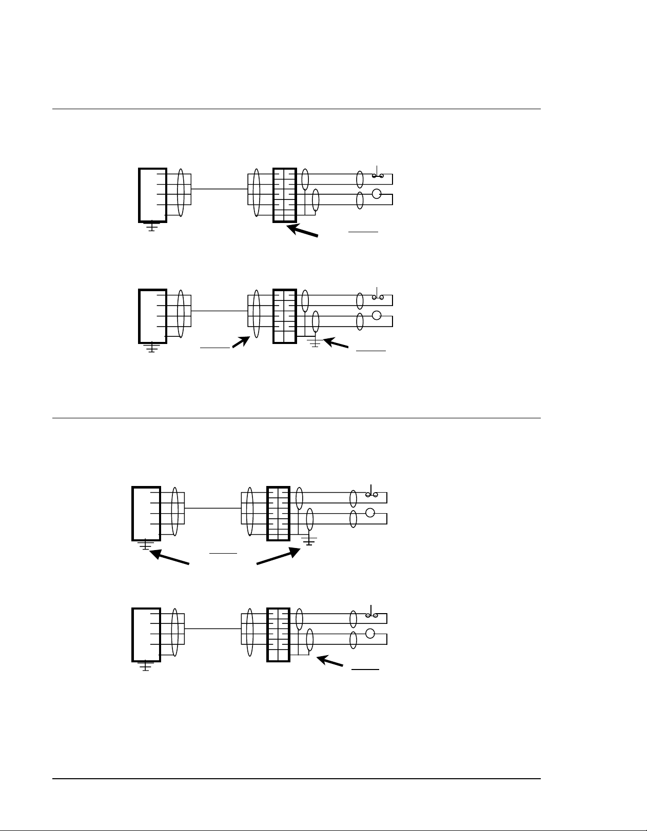
Opto-isolated Inputs
The SMC-2000 provides opto-isolated digital inputs for limit, home, abort, and the uncommitted inputs. All
inputs have the same common ground and are sinking inputs.
If nothing is connected to the inputs, no current flows, resulting in a logic one. A logic zero is generated when
at least 1 mA of current flows through the input.
The 8-Axis SMC provides 16 isolated inputs and 8 additional TTL inputs.
SMC-2000 User's Guide Hardware Interface
3
••••
Page 23
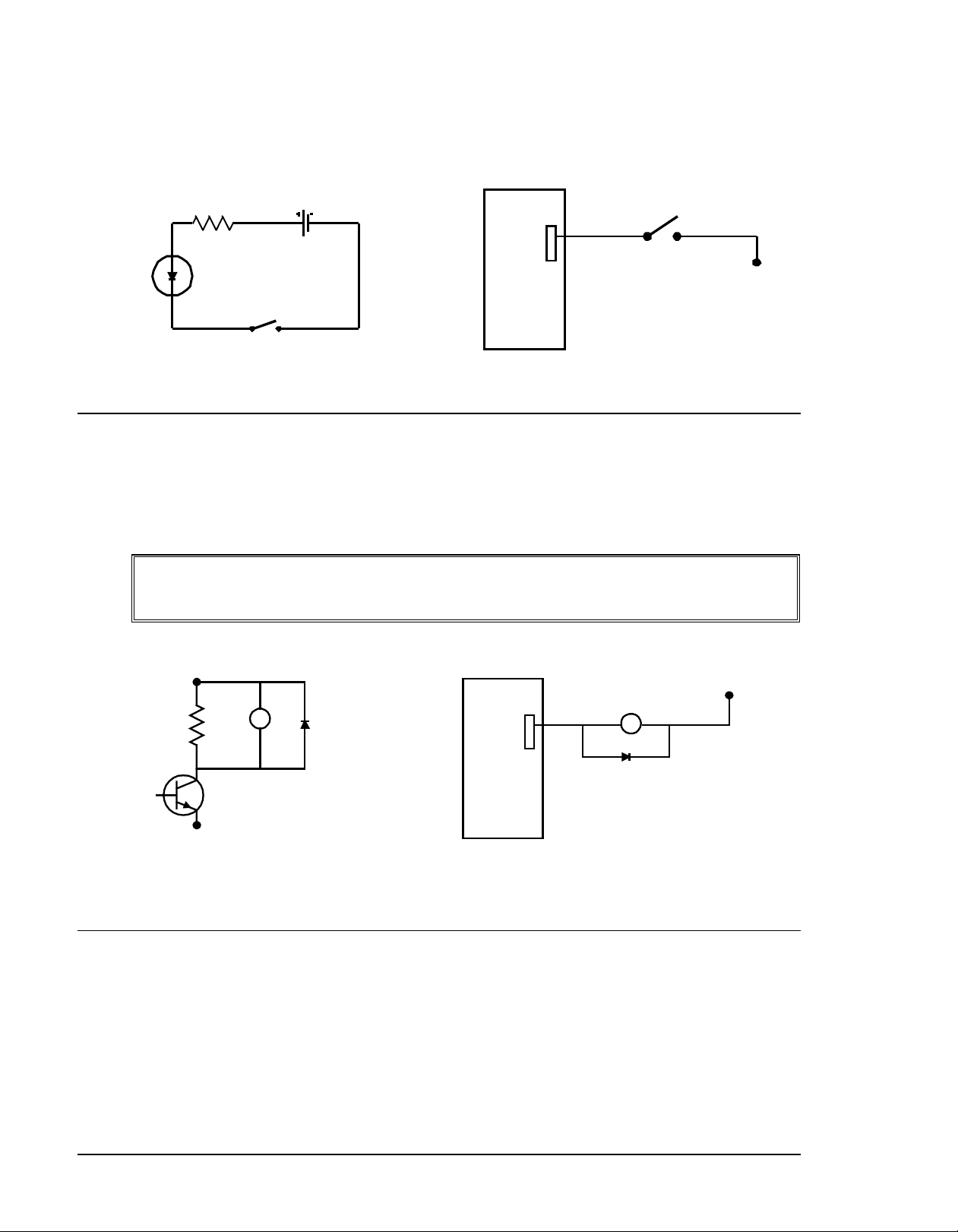
Figure 3-3 - Digital input diagram
Outputs
The SMC-2000 provides several output signals including eight general outputs, and four amplifier enable signals
AEN. All the output signals are 24 volts and are sinking outputs. The maximum current draw is 600 mA per
point, and a total of 800 mA per group of eight i.e. outputs 1-8, 9-16 ... The 8-Axis SMC provides an additional
eight outputs.
WARNING: All inductive loads (Brakes, Relay Coils,...) should have a flyback diode
connected across them to absorb any back EMF produced by that load. The flyback diode
should be placed as close to the load as possible.
+24
VDC
SWITCH
0 V
SMC
I/O
SWITCH
0 V
+24
VDC
LOAD
0 V
Figure 3-4 - Digital output diagram
Analog Inputs
The SMC-2000 has seven analog inputs configured for the range between -10V and 10V. The inputs are
decoded by a 14-bit A/D decoder. The impedance of these inputs is 10 KΩ.
SMC
I/O
LOAD
+24
VDC
4
Hardware Interface SMC-2000 User's Guide
••••
Page 24
Amplifier Interface
The SMC-2000 generates +/-10 Volt range analog signal, ACMD, and ground for each axis. This signal is input
to power amplifiers which have been sized to drive the motors and load. For best performance, the amplifiers
should be configured for a current mode of operation with no additional compensation. The gain should be set
such that a 10 Volt input results in the maximum required current.
The SMC-2000 also provides an AEN, amplifier enable signal, to control the status of the amplifier. This signal
toggles when the watchdog timer activates, when a motor-off command is given, or when OE1 (Off-on-error is
enabled) command is given and the position error exceeds the error limit. As shown in Figure 3-3, AEN can be
used to disable the amplifier for these conditions.
The standard configuration of the AEN signal is 24 VDC active low.
SMC-2000
Figure 3-5 - Connecting AEN to an amplifier
Motors with Brakes
A separate 24 VDC power supply should be used to power the brakes because holding brakes typically generate
large power spikes when they are de-energized.
Severe damage may result when connecting the same power supply to the SMC and the
brake!
Yaskawa recommends that all inductive loads have a diode across them to absorb back EMF.
Step Motors
ACMD
AEN
GND
INPUT
ENABLE
GND
AMP
To connect step motors to the SMC 2000 you must follow this procedure:
1. For each axis that is a stepper, a jumper wire is necessary between ground pin 23 on the AE1 or AE2
connector and the axis stepper mode jumper pin on the AE connector. Newer controllers already have this
jumper wire installed during assembly.
2. Connect step and direction signals from the axis connector pins with the labels, STEP (pin 12) and
SEN/DIR (pin 13) to respective signals on your step motor amplifier. The signals are 5V TTL level.
Consult the documentation for your step motor amplifier.
3. Configure the SMC 2000 for motor type using the MT command. You can configure the SMC 2000 for
active high or active low pulses. Use the command MT 2 for active high step motor pulses and MT -2 for
active low step motor pulses. See the Commands section of this manual for details.
SMC-2000 User's Guide Hardware Interface
5
••••
Page 25

The pulse output signal has a 50% duty cycle. Step motors operate open loop and do not require encoder
feedback. When a stepper is used, the auxiliary encoder for the corresponding axis is unavailable for an external
connection. If an encoder is used for position feedback, connect the encoder to the main encoder input
corresponding to that axis. The commanded position of the stepper can be interrogated with RP or DE. The
encoder position can be interrogated with TP.
The frequency of the step motor pulses can be smoothed with the filter parameter, KS. The KS parameter has a
range between 1 and 16, where 16 implies the largest amount of smoothing.
The SMC 2000 profiler commands the step motor amplifier. All SMC 2000 motion commands apply such as
PR, PA, VP, CR and JG. The acceleration, acceleration, slew speed, and S-curve filtering are also used.
However, since step motors run open loop, the PID filter does not function and the position error is not
generated.
When configured for stepper motor operation, the SMC 2000 can accept encoder signals into the main encoder
inputs. This is useful for monitoring encoder position to insure that encoder position is consistent with
commanded position.
Note: When configured for step motors, the encoder inputs can not be used for closed loop position control and
the auxiliary encoder inputs are not available.
6
Hardware Interface SMC-2000 User's Guide
••••
Page 26

SMC-2000 User's Guide Communication - RS232
Page 27
Communication - RS232
RS232 Ports
The SMC-2000 has two RS232 ports. The main port can be configured by the factory, and the auxiliary port
can be configured with the software command CC. The auxiliary port can either be configured as a general port
or for the daisy-chain communications. The auxiliary port configuration can be saved using the Burn (BN)
instruction. The RS232 ports also have a clock synchronizing line that allows synchronization of motion on
more than one controller.
The RS232 pin-out description for the main and auxiliary port is given below. Note, the auxiliary port is
essentially the same as the main port except inputs and outputs are reversed. The SMC-2000 may also be
configured by the factory for RS422. These pin-outs are also listed below.
RS232 - Main Port {COM 1}
1 CTS (-) output 6 CTS (-) output
2 Transmit Data (-) output 7 RTS (-) input
3 Receive Data (-) input 8 CTS (-) output
4 RTS (-) input 9 No connect - or - (5V or sample clock with jumpers)
5 Ground
RS232 - Auxiliary Port {COM 2}
1 CTS (-) input 6 CTS (-) input
2 Transmit Data (-) input 7 RTS (-) output
3 Receive Data (-) output 8 CTS (-) input
4 RTS (-) output 9 5V - or - (no connect or sample clock with jumpers)
5 Ground
1
••••
Page 28
*RS422 - Main Port {COM 1}
1 CTS (-) output 6 CTS (+) output
2 Transmit Data (-) output 7 Transmit Data (+) output
3 Receive Data (-) input 8 Receive Data (+) input
4 RTS (-) input 9 RTS (+) input
5 Ground
*RS422 - Auxiliary Port {COM 2}
1 CTS (-) input 6 CTS (+) input
2 Transmit Data (-) input 7 Transmit Data (+) input
3 Receive Data (-) output 8 Receive Data (+) output
4 RTS (-) output 9 RTS (+) output
5 Ground
*Configured for RS422 by factory
Configuration
Configure your PC for 8-bit data, one start-bit, one stop-bit, full duplex and no parity. The baud rate for the
RS232 communication is 19.2 K baud. A lower baud rate may be configured at the factory.
The RS232 main port is configured for handshake mode. In this mode, the RTS and CTS lines are used. The
CTS line will go high whenever the SMC-2000 is not ready to receive additional characters. The RTS line will
inhibit the SMC-2000 from sending additional characters. Note the RTS line goes high for inhibit.
The auxiliary port of the SMC-2000 can be configured either as a general port or for the daisy chain. When
configured as a general port, the port can be commanded to send ASCII messages to another SMC-2000
controller or to a display terminal or panel.
(Configure Communication) at port 2. The command is in the format of:
CC m,n,r,p
where m sets the baud rate, n sets for either handshake or non-handshake mode, r sets for general port or the
auxiliary port, and p turns echo on or off.
m - Baud Rate - 300,1200,4800,9600,19200,38400
n - Handshake - 0=No; 1=Yes
r - Mode - 0=General Port; 1=Daisy-chain
p - Echo - 0=Off; 1=On; Valid only if r=0
Note, for the handshake of the auxiliary port, the roles for the RTS and CTS lines are reversed.
Example:
2
Communication - RS232 SMC-2000 User's Guide
••••
Page 29

CC 1200,0,0,1
Configure communication at port 2, with 1200 baud, no
handshake, general port and echo turned on.
Daisy-Chaining
Up to eight SMC-2000 controllers may be connected in a daisy chain. The daisy-chain connection is
straightforward. One SMC-2000 is connected to the host terminal via the RS232 at port 1, or the main port.
Port 2, or the auxiliary port, of that SMC-2000 is then brought into port 1 of the next SMC-2000, and so on.
The default address of the SMC-2000 is zero, if another address is required each of the SMC-2000’s must be
configured by the factory. Please contact Yaskawa if your application requires daisy-chaining.
To communicate with any one of the SMC-2000s, give the command of %A, where A is the address of the SMC
that you want to communicate with. All instructions following this command will be sent only to the SMC with
that address. Only when a new %A command is given will the instruction be sent to another SMC. The only
exception is "!" command. To talk to all the SMC-2000s in the daisy-chain at one time, insert the character "!"
before the software command. All SMCs receive the command, but only address 0 will echo.
Note: The CC command must be specified to configure the port {P2} of each unit.
Example:
Problem: 6-axis motion system. Address 0 is a 4-axis
SMC-2000-4. A 2-axis SMC-2000-2 is set for Address 1.
Address 0 X Axis is 500 counts
Address 1 X Axis is 700 counts
Software Command Interpretation
%0 Talk only to controller 0 (SMC-2000-4)
PR 500,1000,2000,1500 Specify X,Y,Z,W distances
%1 Talk only to controller 1 (SMC-2000-2)
PR 700,1500 Specify X,Y distances
!BG Begin motion on both controllers
Required Motion:
Y Axis is 1000 counts
Z Axis is 2000 counts
W Axis is 1500 counts
Y Axis is 1500 counts
Synchronizing Sample Clocks
It is possible to synchronize the sample clocks of all SMC-2000's in the daisy chain. This involves burning in
the command, TM-1, in all SMC-2000's except for one SMC-2000, which will be the source. If it is necessary
to synchronize the sample clocks please contact Yaskawa.
Operator Interface
To program an operator interface you need to select a port (either 1 or 2), If you select port 2 it must be
configured by using the Configure Communication (CC) command as shown on page 26. You must also decide
if the port will be a general port or an operator data entry port. NOTE: configuring a port as an operator data
SMC-2000 User's Guide Communication - RS232
3
••••
Page 30

entry port will disable ALL commands sent to that port, see Operator Data Entry Mode in chapter 7 for a
complete description. All serial commands, such as message (MG) or input variable (IN) default to port 1. To
assign serial commands to port 2, you must follow the command with a “{P2}” such as:
IN {P2} “Enter a value”,VALUE
Which will send out the prompt “Enter a value” to port 2, then wait until a return or semi-colon is sent out port
2, and assign the value of the preceding characters to the variable VALUE.
Controller Response to Data
Most SMC-2000 instructions are represented by two characters followed by the appropriate parameters. Each
instruction must be terminated by a carriage return or semicolon.
Instructions are sent in ASCII, and the SMC-2000 decodes each ASCII character (one byte) one at a time. It
takes approximately .5 msec for the controller to decode each command.
After the instruction is decoded, the SMC-2000 returns a colon (:) if the instruction was valid or a question mark
(?) if the instruction was not valid or was not recognized.
For instructions requiring data, such at Tell Position (TP), the SMC-2000 will return the data followed by a
carriage return, line feed and : .
It is good practice to check for : after each command is sent to prevent errors. An echo function is provided to
enable associating the SMC-2000 response with the data sent. The echo is enabled by sending the command EO
1 to the controller.
4
Communication - RS232 SMC-2000 User's Guide
••••
Page 31

SMC-2000 User's Guide Communication - RS232
••••
21
Page 32

Programming Basics
Introduction
The SMC-2000 provides over 100 commands for specifying motion and machine parameters. Commands are
included to initiate action, interrogate status and configure the digital filter.
The SMC-2000 instruction set is BASIC-like and easy to use. Instructions consist of two uppercase letters that
correspond phonetically with the appropriate function. For example, the instruction BG begins motion, and ST
stops the motion.
Commands can be sent "live" for immediate execution by the SMC-2000, or an entire group of commands can
be downloaded into the SMC-2000 memory for execution at a later time. Combining commands into groups for
later execution is referred to as Applications Programming and is discussed in the following chapter.
This section describes the SMC-2000 instruction set and syntax. A complete listing of all SMC-2000
instructions is included in the command reference section.
Command Syntax
SMC-2000 instructions are represented by two ASCII upper case characters followed by applicable arguments.
A space may be inserted between the instruction and arguments. A semicolon or <enter> is used to terminate
the instruction for processing by the SMC-2000 command interpreter.
IMPORTANT: All SMC-2000 commands are sent in upper case.
For example, the command
PR 4000 <enter> Position relative
PR is the two character instruction for position relative. 4000 is the argument which represents the required
position value in counts. The <enter> terminates the instruction. The space between PR and 4000 is optional.
For specifying data for the X,Y,Z and W axes, commas are used to separate the axes and preserve axis order as
X,Y,Z and W. If no data is specified for an axis, a comma is still needed as shown in the examples below. If no
data is specified for an axis, the previous value is maintained. The space between the data and instruction is
optional. For the SMC-2000-8, the eight axes are referred to A,B,C,D,E,F,G,H where X,Y,Z,W and A,B,C,D
may be used interchangeably.
To view the current values for each command, specify the command followed by a ? for each axis requested.
The SMC-2000 provides an alternative method for specifying data.
SMC-2000 User's Guide Programming Basics
1
••••
Page 33

Here data is specified individually using a single axis specified such as X,Y,Z or W (or A,B,C,D,E,F,G or H for
the SMC-2000-8). An equals sign is used to assign data to that axis. For example:
PRZ=1000 Sets the Z axis data as 1000
All axes data may be specified at once using the * symbol. This sets all axes to have the same data. For
example:
PR*=1000 Sets all axes to 1000
Example XYZW Syntax for Specifying Data
PR*=1000 Specify data on all axes as 1000
PRY=1000 Specify Y as 1000
PR 1000 Specify X only as 1000
PR ,2000 Specify Y only as 2000
PR ,,3000 Specify Z only as 3000
PR ,,,4000 Specify W only as 4000
PR 2000,4000,6000,8000 Specify X,Y,Z, and W
PR ,8000,,9000 Specify Y and W only
PR*=? Request X,Y,Z,W values
PR ,? Request Y value only
For SMC-2000-8 only:
PR,,,,,,8000 Specify G axis data as 8000
PRG=8000 Alternative method for specifying G data
Instead of data, some commands request action to occur on an axis or group of axes. For example, ST XY stops
motion on both the X and Y axes. Commas are not required in this case since the particular axis is specified by
the appropriate letter X Y Z or W. If no parameters follow the instruction, action will take place on all axes.
The letter S is used to specify a coordinated motion sequence. For the SMC-2000-8, the eight axes are
commanded with ABCDEFGH or XYZWEFGH where XYZW is used interchangeably with ABCD.
Example XYZW syntax for Requesting Action:
BG X Begin X only
BG Y Begin Y only
BG XYZW Begin all axes
BG YW Begin Y and W only
BG Begin all axes
BG S Begin coordinated sequence
BG SW Begin coordinated sequence and W axis
2
Programming Basics SMC-2000 User’s Guide
••••
Page 34

For the SMC-2000-8 only:
BG ABCDEFGH Begin all axes
BG D Begin D only
Controller Response to Commands
For each valid command entered, the SMC-2000 returns a colon (:). If the SMC-2000 decodes a command as
invalid, it returns a question mark (?).
Note:
The SMC-2000 returns a : for valid commands.
The SMC-2000 returns a ? for invalid commands.
For example, if the command BG is sent in lower case, the SMC-2000 will return a ?.
:bg <enter> invalid command, lower case
? SMC-2000 returns a ?
The command Tell Code, TC1, will return the reason for the ? received for the last invalid command.
:TC1 <enter> Tell Code command
1 Unrecognized command Returned response
There are several coded reasons for receiving a ?. Example codes include unrecognized command (such as
typographical entry or lower case), a command given at improper time, or a command out of range, such as
exceeding maximum speed. A complete listing of all codes is listed in the TC command in the Command
Reference section.
For interrogation instructions such as Tell Position (TP) or Tell Status (TS), the SMC-2000 returns the
requested data on the next line followed by a carriage return and line feed. The data returned is in decimal
format.
Tell Position X :TP X <enter>
data returned 0000000000
Tell Position X and Y :TP XY <enter>
data returned 0000000000,0000000000
The format of the returned data can be set using the Position Format (PF) and Variable Format (VF) command.
:PF 4 <enter> Position Format is 4 integers
:TP X <enter> Tell Position
SMC-2000 User's Guide Programming Basics
3
••••
Page 35

0000 returned data
Command Summary
Each SMC-2000 command is described fully in the command reference section at the end of this manual. A
summary of the commands follows.
The commands are grouped in this summary by the following functional categories:
• Motion
• Program Flow
• General Configuration
• Control Settings
• Status and Error/Limits.
Motion commands are those to specify modes of motion such as Jog Mode or Linear Interpolation, and to
specify motion parameters such as speed, acceleration and deceleration, and distance.
Program flow commands are used in Application Programming to control the program sequencer. They include
the jump on condition command and event triggers such as after position and after elapsed time.
General configuration commands are used to set controller configurations such as setting and clearing outputs,
formatting variables, and motor/encoder type.
The control setting commands include filter settings such as KP, KD, and KI and sample time.
Error/Limit commands are used to configure software limits and position error limits.
4
Programming Basics SMC-2000 User’s Guide
••••
Page 36

Motion
AB Abort Motion
AC Acceleration
BG Begin Motion
CD Contour Data
CM Contour Mode
CR Circle
CS Clear Motion Sequence
DC Deceleration
DT Contour Time Interval
EA Select Master CAM axis
EB Enable CAM mode
EG Start CAM motion for slaves
EM Define CAM cycles for each axis
EP Define CAM table intervals & start point
EQ Stop CAM motion for slaves
ES Ellipse Scaling
ET CAM table entries for slave axes
FE Find Edge
FI Find Index
GA Master Axis for Gearing
GR Gear Ratio
HM Home
IP Increment Position
JG Jog Mode
LE Linear Interpolation End
LI Linear Interpolation Distance
LM Linear Interpolation mode
LT Latch Target
PA Position Absolute
PR Position Relative
SP Speed
ST Stop
TN Tangent
VA Vector acceleration
VD Vector Deceleration
VE Vector Sequence End
VM Coordinated Motion Mode
VP Vector Position
VR Vector speed ratio
SMC-2000 User's Guide Programming Basics
5
••••
Page 37

AB Abort Motion
VS Vector Speed
Program Flow
AD After Distance
AI After Input
AM After Motion Complete
AP After Absolute Position
AR After Relative Distance
AS At Speed
AT After Time
AV After Vector Distance
EN End Program
HX Halt Task
IN Input Variable
II Input Interrupt
JP Jump To Program Location
JS Jump To Subroutine
MC After motor is in position
MF After motion -- forward direction
MG Message
MR After motion -- reverse direction
NO No operation
RE Return from Error Subroutine
RI Return from Interrupt
TW Timeout for in position
WC Wait for Contour Data
WT Wait
XQ Execute Program
ZS Zero Subroutine Stack
General Configuration
AE Absolute Encoder
AF Analog Feedback
AL Arm Latch
BN Burn
BP Burn Program
6
Programming Basics SMC-2000 User’s Guide
••••
Page 38

BV Burn Variables
CB Clear Bit
CC Configure Communications Port 2
CE Configure Encoder Type
CN Configure Switches and Stepper
DA De-Allocate Arrays
DE Define Dual Encoder Position
DL Download
DM Dimension Arrays
DP Define Position
EO Echo Off
LS List
MO Motor Off
MT Motor Type Define
OB Output Bit
OP Output Port
PF Position Format
QU Upload Array
QD Download Array
RA Record Array
RC Record
RD Record Data
RI Interrupt Mask
RS Reset
SB Set Bit
UL Upload
VF Variable Format
SMC-2000 User's Guide Programming Basics
7
••••
Page 39

Control Filter Settings
DV Damping for dual loop
FA Acceleration Feed Forward
FV Velocity Feed Forward
GN Gain
IL Integrator Limit
IT Smoothing Time Constant - Independent
KD Derivative Constant
KI Integrator Constant
KP Proportional Constant
OF Offset
SH Servo Here
TL Torque Limit
TM Sample Time
VT Smoothing Time Constant - Vector
ZR Zero
Status
QY Query Yaskawa Encoder
RP Report Command Position
RL Report Latch
SC Stop Code
TB Tell Status
TC Tell Error Code
TD Tell Dual Encoder
TE Tell Error
TI Tell Input
TP Tell Position
TR Trace
TS Tell Switches
TT Tell Torque
TV Tell Velocity
TY Tell Yaskawa Encoder
Error And Limits
BL Reverse Software Limit
ER Error Limit
8
Programming Basics SMC-2000 User’s Guide
••••
Page 40

FL Forward Software Limit
OE Off on Error
Arithmetic Functions
@SIN Sine
@COS Cosine
@ABS Absolute value
@ASIN Arc Sine
@ACOS Arc Cosine
@FRAC Fraction portion
@INT Integer portion
@RND Round
@SQR Square root
@COM Return 2’s Complement
@IN Return digital input
@AN Return analog input
+ Add
- Subtract
* Multiply
/ Divide
& And
| Or
( ) Parentheses
SMC-2000 User's Guide Programming Basics
9
••••
Page 41

Instruction Set Examples
Below are some examples of simple instructions. It is assumed your system is hooked-up and the motors are
under stable servo control. Note, the colon (:) is returned by the controller and appears on the screen. You do
not need to type the :.
:DP*=0 <enter> Define all axis positions as 0
:PF 6,6,6,6 <enter> Define position format as 6 digits
:PR 100,200,300,400 <enter> Specify X,Y,Z,W position command
:BG <enter> Begin Motion
:TP <enter> Tell Position
00100,00200,00300,00400 Returned Position data
:PR?,?,?,? <enter> Request Position Command
00100,00200,00300,00400 Returned data
:BGX <enter> Begin X axis only
:TPX <enter> Tell X position only
00200 Returned position data
:tpx <enter> Enter invalid command
? TC1 <enter> Controller response - Request error code
1 Unrecognized command Controller response
:VM XY <enter> Specify Vector Mode for XY
:VS 10000 <enter> Specify Vector Speed
:VP 2000,3000 <enter> Specify Vector Segment
:VP 4000,5000 <enter> Specify Vector
:LE <enter> Segment End Vector
:BGS <enter> Begin Coordinated Sequence
:TPXY <enter> Tell X and Y position
004200,005200 Returned data
10
Programming Basics SMC-2000 User’s Guide
••••
Page 42

SMC-2000 User's Guide Programming Basics
••••
11
Page 43

Page 44

_ERx all Axis following error limit (2.0g firmware for Erx=0
_EO all Is echo mode on? status 0=NO 1=YES 1
_EP all CAMMING interval (resolution) counts 1 32767 256
_EQx all Status of ECAM slave status 0 3 0
_ED all The last line that caused a CMDERR line number 0 999 n/a
_EGx all Is CAMMING axis engaged? status 0=NO 1=YES 0
_EMx all Cam cycle for camming (master or slave) counts 0 2147483647 0
_DT all Time interval for contour mode 2
_DVx all Is the axis using dual loop PID? status 0=NO 1=YES 0
_EB all Is CAM mode enabled? status 0=NO 1=YES 0
_DPx all Current encoder position of axis counts -2147483648 2147483647 n/a
_DM all Number of available array locations n/a 0 8000 8000
_DL all Number of available labels n/a 0 254 254
_DEx all Encoder position of the auxiliary encoder counts -2147483648 2147483647 n/a
_DA all Number of available arrays n/a 0 30 30
_DCx all Axis deceleration rate counts/sec
_CS all Current segment number for Vector Mode n/a 0 511 n/a
_CW all Port #1 data adjustment (MG from program,
_CEx all Type of encoder selected configuratio
_CM all Is the contour mode buffer full? status 0=NO 1=YES 0
_BV all Size of the EEPROM bytes 1 megabyte 4 megabyte n/a
_BN all Serial number of the SMC2000 n/a n/a
_BLx all Reverse software limit counts -2147483648 2147483647 -2147483648
_BGx all Is axis in motion? status 0=NO 1=YES n/a
_ALx all High speed position capture status status 0=TRIPPED 1=NOT YET 0
_AV all Distance from the start of vector sequence counts 0 2147483647 0
_AFx all Analog or digital feedback? status 0=DIGITAL 1=ANALOG 0
_AEx D150n19h &
up
Command Firmware Definition units min max default
_AB 2.0g Status of abort input status 0=Aborted 1=OK n/a
_ACx all Axis acceleration rate counts/sec
Command Interrogation List
to disable)
counts 0 32767 16384
mSec 0 8 0
characters have bit 8 set)
The last absolute encoder axis that was read axis 0,1,2 =
N
2
1024 67107840 256000
status 1=SET 2=OFF 2
n
0 15 0
X,Y,Z
2
0 7 n/a
1024 67107840 256000
Page 45

g
p
(
PxST all The last strin
PxCH all The last character received from serial port (x = 1
PxNM all The last number received from serial port (x=1 or
PxCD all Status code of serial port (x = 1 or 2) status -1 3 n/a
_OPx all Entire byte or word of output port (x = output bank
_OEx all Indicates if servo enable signal will shut off if
_OFx all Axis command offset voltage -9.9988 9.9988 0
_MOx all Current state of motor, enabled or not status 0=ENABLED 1=DISABLED 0 / 1
_MTx all Type of motor configuratio
_LZ v2.0 & up Serial port leading zero removal status 0=OFF 1=ON 0
_LTx D150n19j &
_LM all Number of free locations in linear mode buffer n/a 0 511 n/a
_LRx all Reverse Limit Switch status 0=ACTIVE 1=INACTIVE n/a
_LS all Next line that will be executed after current
_KPx all Proportional Constant for PID loop constant 0 1023.875 6 / 1
_LE all Length of the vector counts 0 2147483647 0
_LFx all Forward Limit Switch status 0=ACTIVE 1=INACTIVE n/a
_JGx all Jog speed for that axis counts/sec 0 8000000 25000
_KDx all Derivative Constant for PID loop constant 0 4095.875 64 / 10
_KIx all Integrator for PID loop constant 0 2047.875 0 / 0
_ILx all Integrator limit of the axis voltage -9.9988 9.9988 9.9988
_IPX all Current encoder position of axis counts -2147483648 2147483647 n/a
_ITx all S curve smoothing function value constant 0.004 1 1
_HXx all Thread info 0=NOT
ID D150n19h &
_HMx all State of the home switch status 0=ACTIVE 1=INACTIVE n/a
_FVx all Axis velocity feed forward constant 0 8191 0
_GRx all Gear ratio of the axis constant -127.9999 127.9999 0
_ES all Ellipse scale ratio n/a 0.0001 1 1
_FAx all Axis acceleration feed forward constant 0 8191 0
_FLx all Forward software limit counts -2147483648 2147483647 2147483647
up
subroutine ends
or 2)
2)
0-3)
"_ERX" is exceeded
Distance until stop after a registration mark counts 1 2147483647 ??
up
The part number of an SMC-2000 n/a
received from serial
ort
x = 1 or string 6 chars max n/a
number -2147483648 2147483647 n/a
character 0 255 n/a
n
byte or word 0 65535 0
status 0=NO 1=YES 0
line number 0 999 n/a
RUNNING
-2.5 2.5 1
1=RUNNING 2=AT
TRIPPOINT
n/a
Page 46

_VA all acceleration value for vector mode counts/sec
_VD all Deceleration value for vector mode counts/sec
_VE all Length of vector (all moves in coordinated move
_UL all Number of variables available n/a 0 254 254
_TWx all Time limit that program will wait for axis to get to
_TVx all Velocity of axis (averaged over 256 servo cycles) counts/sec 0 8000000 n/a
_TYx D150n19h &
_TPx all Current encoder position of axis counts -2147483648 2147483647 n/a
_TSx all Status of switches for axis byte 0 255 n/a
_TTx all Current output voltage to amplifier voltage -9.9988 9.9988 0
_TLx all Torque limit of axis voltage 0 9.9988 9.9988
_TM all Servo update cycle for all axes
_TN all Position of first tangent point counts -2147483648 2147483647 0
_TIx all 8 inputs as a decimal or hex value (x = input bank
TIME all Counter since SMC2000 powered on milliseconds 0 2147483647 0
_TDx all Current auxiliary encoder position counts -2147483648 2147483647 n/a
_TEx all Difference between commanded & actual axis
_SPx all Speed parameter of the axis counts/sec 0 8000000 25000
_TB all Status information from controller byte 0 255 1
_TC1 all Error code and message from controller number 0 150 0
_RLx all Encoder value of last latched position counts -2147483648 2147483647 0
_RPx all Current commanded position of the motor counts -2147483648 2147483647 0
_SCx all The Stop Code of the axis code 0 150 1
_RC all Status of record mode status 0= NOT
_RD all Array index that record mode will use next index 0 7999 0
_PRx all Current incremental distance to move (Even if
QY D150n19h &
_PF all Encoder position format digits before
_PAx all Last commanded absolute position if moving,
sequence)
counts 0 2147483647 0
up
The position of an absolute encoder at time of
reading
target position (MCx)
counts -2147483648 2147483647 -2147483648
milliseconds -1 32766 32766
up
2)
move set by PA)
The last ASCII string received from an absolute
position
0-7)
counts -2147483648 2147483647 n/a
µSec
byte 0 255 n/a
encoder
counts -2147483648 2147483647 0
string 6 chars max n/a
otherwise current position
& after
counts -2147483648 2147483647 0
2
2
1024 68431360 256000
1024 68431360 256000
375 20000 1000
RECORDING
-8.4 10.4 10.4
1=RECORDING 0
Page 47

_ZS all Current subroutine depth number 0 16 n/a
_XQx all Current line number being executed (x = thread #) line number -1 999 n/a
_VT all S curve smoothing value for vector mode constant 0.004 1 1
_VS all Vector Speed counts/sec 2 8000000 25000
_VR all Vector speed ratio n/a 0 10 1
_VF all Setting of variable formatting n/a 0 10.4 10.4
_VM all Number of free locations in vector mode buffer n/a 0 511 511
_VPx all Absolute coordinate of the axis in the last
segment
counts -2147483648 2147483647 0
Page 48

Page 49

Programming Motion
Overview
The SMC-2000 provides several modes of motion, including independent positioning and jogging of any axis,
coordinated motion, and electronic gearing. Each one of these modes is discussed in the following sections.
Please note the SMC-2000-2 uses X and Y, the SMC-2000-4 uses X, Y, Z and W.
The SMC-2000-8 uses the axes A, B, C, D, E, F, G, and H. For SMC-2000-8, the axes A, B, C, D can be
referred to interchangeably as X,Y,Z,W.
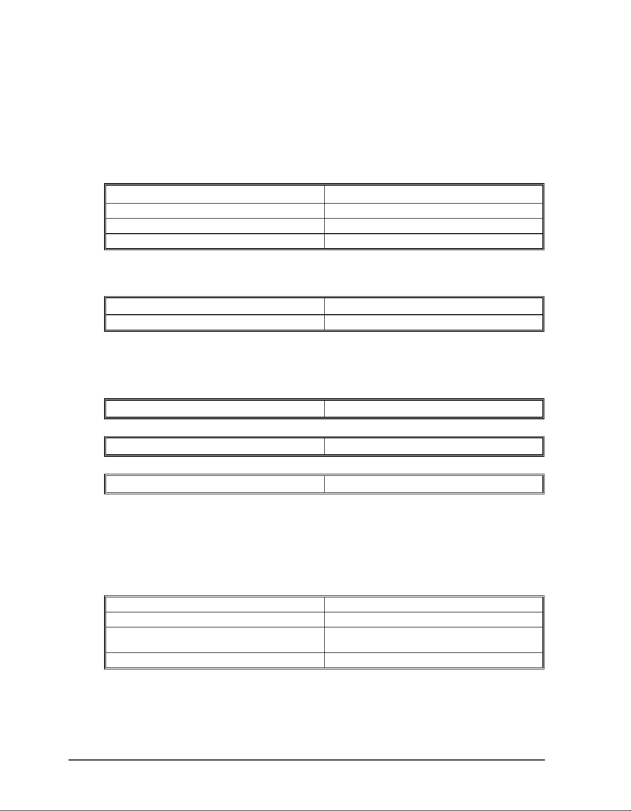
The example applications described below will help guide you to the appropriate mode of motion.
Example Application Mode of Motion Commands
Absolute or relative positioning where
each axis is independent and follows
prescribed velocity profile.
Velocity control where no final
endpoint is prescribed. Motion stops
on Stop command.
Motion Path described as incremental
position points versus time.
2,3 or 4 axis coordinated motion
where path is described by linear
segments.
2-D motion path consisting of arc
segments and linear segments, such as
engraving or quilting.
Independent Axis Positioning PA,PR
Independent Jogging JG
Contour Mode CM
Linear Interpolation LM
Coordinated Motion VM
SP,AC,DC
AC,DC
ST
CD
DT
WC
LI,LE
VS
VA,VD
VP
CR
VS
VA,VD
VE
SMC-2000 User’s Guide Programming Motion
1
••••
Page 50

Third axis must remain tangent to 2-D
motion path, such as knife cutting.
Electronic gearing where slave axes
are scaled to master axis which can
move in both directions.
Master/slave where slave axes must
follow a master such as conveyer
speed.
Moving along arbitrary profiles or
mathematically prescribed profiles
such as sine or cosine trajectories.
Teaching or Record and Play Back Contour Mode with Automatic Array
Backlash Correction Dual Loop DE
Motion Smoothing Applies to all independent modes of
Coordinated motion with tangent axis
specified
Electronic Gearing GA
Electronic Gearing GA
Contour Mode CM
Capture
motion i.e. PR, PA, JG. Smoothes
motion to eliminate vibrations due to
jerk (discontinuities in acceleration)
VM
VP
CR
VS,VA,VD
TN
VE
GR
GR
CD
DT
WC
CM
CD
DT
WC
RA
RD
RC
IT
Independent Axis Positioning
In this mode, motion between the specified axes is independent, and each axis follows its own profile. The user
specifies the desired absolute (PA) or relative position (PR), slew speed (SP), acceleration ramp (AC), and
deceleration ramp (DC), for each axis. On begin (BG), the SMC-2000 profiler generates the corresponding
trapezoidal or triangular velocity profile and position trajectory. A new command position along the trajectory
is generated every sample period. Motion is complete when the last position command or target position is
generated by the SMC-2000 profiler. The actual motor motion may not be complete at this point, however, the
next motion command may be specified.
The Begin (BG) command can be issued for all axes either simultaneously or independently. XYZ or W axis
specifiers are required to select the axes for motion. No axes specifier implies motion on all the axes. For the
SMC-2000-8, ABCDEFGH axes specifiers are used where XYZ and W may be interchanged with ABCD.
The speed (SP) and the acceleration (AC) can be changed at any time during motion, however, the deceleration
(DC) and position (PR or PA) cannot be changed until motion is complete. Remember, motion is complete
when the profiler is finished, not when the actual motor is in position. The Stop command (ST) can be issued at
any time to decelerate the motor to a stop before it reaches its final position.
2
Programming Motion SMC-2000 User's Guide
••••
Page 51

A new position target (IP) may be specified during motion as long as the additional move is in the same
direction. Here, the user specifies the desired position increment, n. The new target is equal to the old target
plus the increment, n. Upon receiving the IP command, a revised profile will be generated for motion towards
the new end position. The IP command does not require a begin. Note: If the motor is not moving, the IP
command is equivalent to the PR and BG command combination.
Independent Axis Command Summary
PR x,y,z,w Specifies relative distance
PA x,y,z,w Specifies absolute position
SP x,y,z,w Specifies slew speed
AC x,y,z,w Specifies acceleration rate
DC x,y,z,w Specifies deceleration rate
BG XYZW Starts motion
ST XYZW Stops motion before end of move
IP x,y,z,w Changes position target
AM XYZW Trippoint for profiler complete
MC XYZW Trippoint for "in position"
For the SMC-2000-8:
Use a,b,c,d,e,f,g,h to specify axis data above.
Example - Absolute Position
PA 10000,20000 Specify absolute X,Y position
AC 1000000,1000000 Acceleration for X,Y
DC 1000000,1000000 Deceleration for X,Y
SP 50000,30000 Speeds for X,Y
BG XY Begin motion
Example - Multiple Move Sequence
Required Motion Profiles
X-Axis 500 counts Position
10000 count/sec Speed
500000 counts/sec2 Acceleration
Y-Axis 1000 counts Position
15000 count/sec Speed
500000 counts/sec2 Acceleration
Z-Axis 100 counts Position
5000 counts/sec Speed
500000 counts/sec2 Acceleration
SMC-2000 User’s Guide Programming Motion
3
••••
Page 52

Start X and Y motion at the same time. After 20 msec, start Z motion. If input 1 is high, stop Y motion.
#A Begin Program
PR 500,1000,100 Specify position
SP 10000,15000,5000 Specify speed
AC 500000,500000,500000 Specify acceleration
DC 500000,500000,500000 Specify deceleration
BG XY Begin X and Y
WT 20;BG Z Wait 20 msec and begin
JP #B,@IN[1]=0 Jump if input 1 is low
STY Stop Y
#B;EN End Program
Fig. 6.1 shows the velocity profiles for the X,Y and Z axis.
VELOCITY
(COUNTS/SEC)
10000
5000
0
INPUT 1
Figure 6.1 - Velocity Profiles of XYZ
10 20 30 40 50 60
Independent Jogging
In this mode, the user specifies the jog speed (JG), acceleration (AC), and the deceleration (DC) rate for each
axis. On begin (BG), the motor accelerates up to speed and continues to jog at that speed until a new speed or
stop (ST) command is issued. The direction of motion is specified by the sign of the JG parameters.
The jog mode of motion is very flexible because the speed, direction, and acceleration can be changed during
motion. The IP command can also be used to instantly change the motor position. Upon receiving this
command, the motor will instantly try to servo to a position, which is equal to the specified increment plus the
current position. This command is useful when trying to synchronize the position of two motors while they are
moving.
It should be noted that the controller operates as a closed-loop position controller even while in the jog mode.
The SMC-2000 converts the velocity profile into a position trajectory where a new position target is generated
every sample period. This method of control results in precise speed regulation with phase lock accuracy.
TIME (MS)
4
Programming Motion SMC-2000 User's Guide
••••
Page 53

Jogging Command Summary
JG +/-x,y,z,w Specifies jog speed and direction
AC x,y,z,w Specifies acceleration rate
DC x,y,z,w Specifies deceleration rate
BG XYZW Begins motion
ST XYZW Stops motion
IP x,y,z,w Increments position instantly
For the SMC-2000-8:
Use a,b,c,d,e,f,g,h to specify axis data above.
Example - Jog in X only
Jog X motor at 50000 count/s. After X motor is at its jog speed, begin jogging Z in reverse direction at 25000
count/s.
#A
AC 20000,,20000 Specify X,Z acceleration
DC 20000,,20000 Specify X,Z deceleration
JG 50000,,-25000 Specify X,Z speed and direction
BG X Begin X motion
AS X After X at speed
BG Z Begin Z motion
EN
Example - Joystick Jogging
The jog speed can also be changed using an analog input such as a joystick. Assume that for a 10 Volt input the
speed must be 50000 counts/sec. Therefore, the calibration factor is 50000/8191 since the SMC-2000 uses a 14bit ADC resulting in 8191 counts for 10 Volts.
#JOY Label
JG0 Set in Jog Mode
BGX Begin motion
#B Label for loop
V1 =@AN[1] Read analog input
VEL=V1*50000/8191 Compute speed
JG VEL Change JG speed
JP #B Loop
SMC-2000 User’s Guide Programming Motion
5
••••
Page 54

Linear Interpolation Mode
The SMC-2000 provides a linear interpolation mode for 2,3 or 4 axes (up to 8 axes for the SMC-2000-8). Here,
motion between the axes is coordinated to maintain the prescribed vector speed, acceleration, and deceleration
along the specified path. The motion path is described in terms of incremental distances for each axis. Several
incremental segments may be given in a continuous move sequence, making the linear interpolation mode ideal
for following a piece-wise linear path. There is no limit to the total move length.
The LM XYZW command selects the Linear Interpolation mode and axes for interpolation. For example, LM
YZ selects only the Y and Z-axes for linear interpolation. For the SMC-2000-8, use ABCDEFGH axis specifies
where XYZW may be used interchangeably with ABCD.
The LM command only needs to be specified once unless the axes for linear interpolation change, or another
mode such as VM is given.
The LI x,y,z,w or LI a,b,c,d,e,f,g,h command specifies the incremental move distance for each axis. This means
motion is prescribed with respect to the current axis position. Up to 511 incremental move segments may be
given prior to the Begin Sequence (BGS) command. Once motion has begun, additional LI segments may be
specified.
The clear sequence (CS) command can be used to remove LI segments stored in the buffer prior to the start of
the motion. To stop the motion, use the instructions STS or AB. The ST command causes a decelerated stop,
while the AB command gives an instantaneous stop and aborts the program, while AB1 aborts the motion only.
The Linear End (LE) command must be used to specify the end of a linear move sequence. This command tells
the controller to decelerate to a stop following the last LI command. If an LE command is not given, an Abort
AB1 must be used to abort the motion sequence.
It is the responsibility of the user to keep enough LI segments in the SMC-2000 sequence buffer to ensure
continuous motion. If the controller receives no additional LI segments and no LE command, the controller will
stop motion instantly at the last vector. There will be no controlled deceleration. LM? or _LM returns the
available spaces for LI segments that can be sent to the buffer. 511 returned means the buffer is empty and 511
LI segments can be sent. A zero means the buffer is full and no additional segments can be sent. As long as the
buffer is not full, LI segments can be sent at the COM port baud rate.
The instruction _CS returns the segment counter. As the segments are processed, _CS increases, starting at zero.
This function allows the host computer to determine which segment is being processed.
Additional commands for linear interpolation are VS n, VA n, and VD n for specifying the vector speed,
acceleration and deceleration. The AV n command is the After Vector trippoint, which waits for the vector
distance of n to occur.
For example, note the following program:
DP 0,0 Define position
LMXY Specify axes for linear interpolation
LI 5000,0 Specify XY distances
LI 0,5000 Specify XY distances
LE Specify end move
VS 4000 Specify vector speed
BGS Begin sequence
AV 4000 After vector distance 4000
VS 1000 Specify vector speed
AV 5000 After vector distance 5000
VS 4000 Specify vector speed
6
Programming Motion SMC-2000 User's Guide
••••
Page 55

EN End program
Here the XY system is required to perform 90° turn. In order to slow the speed around the corner, we use the
AV 4000 trippoint, which slows the speed to 1000 count/s. Once the motors reach the corner, we can increase
the speed, back to 4000 cts/s, with the trippoint AV 5000.
The instruction AV can be used as an operand. _AV returns the distance along the motion sequence.
The instruction _VP returns the absolute coordinate of the last data point along the trajectory. This enables the
host to command motion backward in case of tool break.
For example, note the program shown above. Consider the first motion segment, where the X-axis moves
toward the point X=5000. Now suppose that when X=3000, the controller is interrogated.
The response to _AV will be 3000. The response to _CS is 0 and the responses to _VPX and _VPY are zeros
for both.
Now suppose that the interrogation is repeated at the second segment when Y=2000. The response to _AV at
this point is 7000, _CS equals 1, _VPX=5000 and _VPY=0.
It should be noted that the SMC-2000 computes the vector speed based on the axes specified in the LM mode.
For example, LM XYZ designates linear interpolation for the X, Y, and Z-axes. The speed of these axes will be
computed from VS
2
=XS2+YS2+ZS2, where XS, YS and ZS are the speed of the X, Y and Z-axes. If the LI
command specifies only X and Y, the speed of Z will still be used in the vector calculations. The controller
always uses the axis specifications from LM, not LI, to compute the speed.
Command Summary - Linear Interpolation
LM XYZW Specify axes for linear interpolation
LM ABCDEFGH Specify axes for linear interpolation (SMC-2000-8)
LI x,y,z,w
LI a,b,c,d,e,f,g,h
_LM or LM? Returns number of available spaces for linear segments in
VS n Specify vector speed
VA n Specify vector acceleration
VD n Specify vector deceleration
BGS Begin Linear Sequence
CS Clear sequence
_CS Segment counter
_VPm Return coordinate of last point, where m=X,Y,Z or W or
LE Linear End- Required at end of LI command sequence
_LE or LE? Returns length of vector (resets after 2147483647)
AMS Trippoint for After Sequence complete
AV n Trippoint for After Relative Vector distance ,n
_AV Return distance traveled
Specify incremental distances relative to current position
SMC-2000 sequence buffer. Zero means buffer full. 511
means buffer empty.
A,B,C,D,E,F,G or H
SMC-2000 User’s Guide Programming Motion
7
••••
Page 56

Example - Linear Move
SVZVW
Make a coordinated linear move in the ZW plane. Move to coordinates 40000,30000 counts at a vector speed of
100,000 counts/sec and vector acceleration of 1000000 counts/sec
LM ZW Specify axes for linear interpolation
LI,,40000,30000 Specify ZW distances
LE Specify end move
VS 100000 Specify vector speed
VA 1000000 Specify vector acceleration
VD 1000000 Specify vector deceleration
BGS Begin sequence
2
.
Note that the above program specifies the vector speed, VS, and not the actual axis speeds VZ and VW. The
axis speeds are determined by the SMC-2000 from:
V
=+
22
The resulting profile is shown in Figure 6.2.
POS W
30000
0
0
POS Z
40000
FEEDRATE
0 0.1 0.5 0.6
VELOCITY
V Z
VELOCITY
V W
Figure 6.2 - Linear Interpolation
8
Programming Motion SMC-2000 User's Guide
••••
Page 57

Example - Multiple Moves
Make a coordinated linear move in the XY plane. The Arrays VX and VY are used to store 750 incremental
distances that have been filled by the program #LOAD.
#LOAD Load Program
DM VX [750],VY [750] Define Array
COUNT=0 Initialize Counter
N=0 Initialize position increment
#LOOP LOOP
VX [COUNT]=N Fill Array VX
VY [COUNT]=N Fill Array VY
N=N+10 Increment position
COUNT=COUNT+1 Increment counter
JP #LOOP,COUNT<750 Loop if array not full
#A Label
LM XY Specify linear mode for XY
COUNT=0 Initialize array counter
#LOOP2;JP#LOOP2,_LM=0 If sequence buffer full, wait
JS#C,COUNT=500 Begin motion on 500th segment
LI VX[COUNT],VY[COUNT] Specify linear segment
COUNT=COUNT+1 Increment array counter
JP #LOOP2,COUNT<750 Repeat until array done
LE End Linear Move
AMS After Move sequence done
MG "DONE" Send Message
EN End program
#C;BGS;EN Begin Motion Subroutine
Coordinated Motion Sequences
The SMC-2000 allows a long 2-D path consisting of linear and arc segments to be prescribed. Motion along the
path is continuous at the prescribed vector speed even at transitions between linear and circular segments. The
SMC-2000 performs all the complex computations of linear and circular interpolation, freeing the host PC from
this time intensive task.
The coordinated motion mode is similar to the linear interpolation mode. Here, any pair of two axes may be
selected for coordinated motion consisting of linear and circular segments. In addition, a third axis can be
controlled such that it remains tangent to the motion of the selected pair of axes.
The VM m,n,p command specifies the axes. m,n are the coordinated pair and p is the tangent. For example,
VM X, W, Z selects the XW axes for coordinated motion and the Z-axis as the tangent. Commas are not
required.
SMC-2000 User’s Guide Programming Motion
9
••••
Page 58

The motion segments are described by two commands, VP for linear and CR for circular segments. The VP x,y
θ, δ
command specifies the end point coordinate of the linear segment, in reference to the starting point. CR r,
define a circular arc with a radius r, starting angle of
corresponds to the positive horizontal direction and for both
θ, and a traversed angle δ. The notation for θ is that zero
θ and δ, the counter-clockwise (CCW) rotation is
positive.
Up to 511 segments of CR or VP may be given prior to the Begin Sequence (BGS) command. Once motion
starts, additional segments may be added.
The Clear Sequence (CS) command can be used to remove VP and CR stored in the buffer prior to the start of
the motion. To stop the motion, use the instructions STS or AB1. ST stops motion at the specified deceleration.
AB1 aborts the motion instantaneously.
The Vector End (VE) command must be used to specify the end of the coordinated motion. This command
requires the controller to decelerate to a stop following the last motion requirement. If a VE command is not
given, an Abort (AB1) must be used to abort the coordinated motion sequence.
It is the responsibility of the user to keep enough motion segments in the SMC-2000 sequence buffer to ensure
continuous motion. If the controller receives no additional motion segments and no VE command, the controller
will stop motion instantly at the last vector. There will be no controlled deceleration. LM? or _LM returns the
available spaces for motion segments that can be sent to the buffer. 511 returned means the buffer is empty and
511 segments can be sent. A zero means the buffer is full and no additional segments can be sent. As long as
the buffer is not full, additional segments can be sent at the COM port baud rate.
The instruction _CS returns the segment counter. It allows the host to determine the motion segment being
executed.
Additional commands for coordinated motion are VS n, VA n and VD n for specifying the vector speed,
acceleration, and deceleration. The AV n command is the After Vector trippoint, which waits for the vector
relative distance of n to occur.
The AV trippoint is useful in changing the parameters, such as the vector speed along the sequence.
When AV is used as an operand, _AV returns the distance traveled along the sequence.
The instruction _VPX and _VPY can be used to return the coordinates of the last point specified along the path.
Example:
Traverse the path shown in Fig. 6.3. Feed rate is 20000 counts/sec. Plane of motion is XY.
VM XY Specify motion plane
VS 20000 Specify vector speed
VA 1000000 Specify vector acceleration
VD 1000000 Specify vector deceleration
VP -4000,0 Segment AB
CR 1500,270,-180 Segment BC
VP 0,3000 Segment CD
CR 1500,90,-180 Segment DA
VE End of sequence
BGS Begin Sequence
10
Programming Motion SMC-2000 User's Guide
••••
Page 59

The resulting motion starts at the point A and moves toward points B, C, D, A. Suppose that we interrogate the
controller when the motion is halfway between the points A and B.
_AV returns 2000
_CS returns 0
_VPX and _VPY return the absolute coordinate of the point A
Next, suppose that the interrogation is repeated at a point, halfway between the points C and D.
_AV returns 4000+1500
_CS returns 2
_VPX,_VPY return the coordinates of the point C
C (-4000,3000)
R = 1500
B (-4000,0)
Figure 6.3 - The Required Path
Tangent Motion
π+2000=10,712
D (0,3000)
A (0,0)
Several applications, such as cutting, require a third axis (i.e. a knife blade), to remain tangent to the coordinated
motion path. To handle these applications, the SMC-2000 allows one axis to be specified as the tangent axis.
The VM command provides parameter specifications for describing the coordinated axes and the tangent axis.
VM m,n,p m,n specifies coordinated axes p specifies tangent axis such
as X,Y,Z,W or A,B,C,D,E,F,G,H. p=N turns off tangent
axis
Before the tangent mode can operate, it is necessary to assign an axis via the VM command and define its offset
and scale factor via the TN m,n command. m defines the scale factor in counts/degree and n defines the tangent
position that equals zero degrees in the coordinated motion plane. The _TN can be used to return the initial
position of the tangent axis.
Example:
Assume an XY table with the Z-axis controlling a knife. The Z-axis has a 2000 quad counts/rev encoder and has
°
been initialized after power-up to point the knife in the +Y direction. A 180
radius of 3000, center at the origin and a starting point at (3000,0). The motion is CCW, ending at (-3000,0).
SMC-2000 User’s Guide Programming Motion
circular cut is desired, with a
••••
11
Page 60

Note that the 0° position in the XY plane is in the +X direction. This corresponds to the position -500 in the Zaxis, and defines the offset. The motion has two parts. First, X,Y and Z are driven to the starting point, and
later, the cut is performed. Assume that the knife is engaged with output bit 1.
#EXAMPLE Example program
VM XYZ XY coordinate with Z as tangent
TN 2000/360,-500 2000/360 counts/degree, position -500 is 0 degrees in XY
plane
CR 3000,0,180 3000 count radius, start at 0 and go to 180 CCW
VE End vector
CB1 Disengage knife
PA 3000,0,_TN Move X and Y to starting position, move Z to initial
tangent position
BG XYZ Start the move to get into position
AM XYZ When the move is complete
SB1 Engage knife
WT50 Wait 50 msec for the knife to engage
BGS Do the circular cut
AMS After the coordinated move is complete
CB1 Disengage knife
MG "ALL DONE"
EN End program
Coordinated Motion Sequence Instructions - Summary
VM m,n,p Specifies plane for the motion sequence such as X,Y or
Z,W. p specifies tangent axis.
VP m,n Return coordinate of last point, where m=X,Y,Z or W.
_VPm Specifies the end point of a segment in reference to the
starting point of the sequence.
CR r,Θ, ±∆Θ Specifies arc segment where r is the radius, Θ is the starting
angle and ∆Θ is the travel angle. Positive direction is
CCW.
VS n Specifies vector speed or feed rate of sequence.
VA n Specifies vector acceleration along the sequence.
VD n Specifies vector deceleration along the sequence.
BGS Begin motion sequence.
AV n Trippoint for After Relative Vector distance, n.
_AV Return distance traveled.
AMS Holds execution of the next command until the Motion
Sequence is completed.
12
Programming Motion SMC-2000 User's Guide
••••
Page 61

_LM or LM? Return number of available spaces for linear and circular
TN m,n Tangent scale and offset.
ES m,n Ellipse scale factor.
CS Clear sequence.
_CS Segment counter.
Electronic Gearing
This mode allows 1,2 or 3 axes (or 4,5,6,7 axes for the SMC-2000-8) to be electronically geared to one driven
master axis, or all axes to be geared to an auxiliary encoder. The master may rotate in both directions and the
geared axes will follow at the specified gear ratio. The gear ratio may be different for each axis and changed
during motion.
The command GAX or GAY or GAZ or GAW (or GAA or GAB or GAC or GAD or GAE or GAF or GAG or
GAH for SMC-2000-8) specifies the master axis. There may only be one master. GR x,y,z,w specifies the gear
ratios for the slaves where the ratio may be a number between +/-127.9999 with a fractional resolution of .0001.
GR 0,0,0,0 turns off electronic gearing for any set of axes. A limit switch will also disable electronic gearing for
that axis. GR causes the specified axes to be geared to the actual position of the master. The master axis is
commanded with motion commands such as PR, PA or JG.
segments in SMC-2000 sequence buffer. Zero means
buffer is full. 511 means buffer is empty.
An alternative gearing method is to synchronize the slave motor to the commanded vector motion of several
axes performed by GAS. For example, if the X and Y motor form a circular motion, the Z axis may move in
proportion to the vector move. Similarly, if X,Y and Z perform a linear interpolation move, W can be geared to
the vector move.
Electronic gearing allows the geared motor to perform a second independent or coordinated move in addition to
the gearing. For example, when a geared motor follows a master at a ratio of 1:1, it may be advanced an
additional distance with PR, or JG, commands, or VP, or LI.
Command Summary - Electronic Gearing
GA n Specifies master axis for gearing where n = X,Y,Z or W or
A,B,C,D,E,F,G,H for main encoder as master
n = XC,YC,ZC or WC or AC, BC, CC, DC, EC,
FC,GC,HC for commanded position as master
n=S vector move for master
GR x,y,z,w Sets gearing mode and gear ratio for slave axes. 0 disables
electronic gearing for specified axis.
GR a,b,c,d,e,f,g,h Sets gearing mode and gear ratio for slave axes. 0 disables
electronic gearing for specified axis.
MR x,y,z,w Trippoint for motion past assigned point in reverse
direction. Only one field may be used.
MF x,y,z,w Trippoint for motion past assigned point in forward
direction. Only one field may be used.
SMC-2000 User’s Guide Programming Motion
••••
13
Page 62

Example - Simple Master Slave
Master axis moves 10000 counts at slew speed of 100000 counts/sec. Y is defined as the master. X,Z,W are
geared to master at ratios of 5,-.5 and 10 respectively.
GAY Specify master axes as Y
GR 5,,-.5,10 Set gear ratios
PR ,10000 Specify Y position
SP ,100000 Specify Y speed
BGY Begin motion
Example - Electronic Gearing
Run two geared motors at speeds of 1.132 and -0.045 times the speed of an external master. The master motor
is driven externally at speeds between 0 and 1800 RPM (2000 counts/rev encoder).
Solution: Use a SMC-2000-4 controller, where the Z-axis is the master and X and Y are the geared axes.
M0 Z Turn Z off, for external master
GA Z Specify master axis
GR 1.132,-.045 Specify gear ratios
Now suppose the gear ratio of the X-axis is to change on the fly to 2. This can be achieved by commanding:
GR 2
In several applications where both the master and the follower are controlled by the SMC-2000 controller, it
may be desired to synchronize the follower with the commanded position of the master, rather than the actual
position. This eliminates the coupling between the axes that may lead to oscillations.
For example, assume that a gantry is driven by two axes, X,Y, on both sides. The X-axis is the master and the
Y-axis is the follower. To synchronize Y with the commanded position of X, use the instructions:
GACX Specify master as commanded position of X
GR,1 Set gear ratio for Y as 1:1
PR 3000 Command X motion
BG X Start motion
You may also perform profiled position corrections in the electronic gearing mode. Suppose, for example, that
you need to advance the slave 10 counts. Simply command
IP,10
which is equivalent to PR,10; BGY.
Often the correction is quite large. Such requirements are common on synchronizing cutting knives or conveyor
belts.
14
Programming Motion SMC-2000 User's Guide
••••
Page 63

Example - Synchronize two conveyor belts with trapezoidal
velocity correction.
GAX Define master axis as X
GR,2 Set gear ratio 2:1 for Y
PR,300 Specify correction distance
SP,5000 Specify correction speed
AC,100000 Specify correction acceleration
DC,100000 Specify correction deceleration
BGY Start correction
Contour Mode
The SMC-2000 also provides a contouring mode. This mode allows any arbitrary position curve for 1,2,3 or 4
(5,6,7 or 8 axes for SMC-2000-8) axes to be prescribed which is ideal for following computer generated paths
such as parabolic, spherical or user-defined profiles. Here, the path is not limited to straight line and arc
segments. Also, the path length may be infinite.
The Contour Mode (CM) command specifies which axes are to be contoured. Any combination of 1,2,3 or 4
axes (5,6,7 or 8 axes for SMC-2000-8) may be used. For example, CMXZ specifies contouring on the X and Zaxes. Axes non-contouring may be operated in other modes.
The contour is described by position increments, CD x,y,z,w over a time interval, DT n. For the SMC-2000-8,
the contour is described by CD a,b,c,d,e,f,g,h.
The time interval must be 2n ms, where n is a number between 1 and 8. The controller performs linear
interpolation between the specified increments, where one point is generated for each millisecond.
Consider, for example, the trajectory shown in Fig. 6.4. The position X may be described by the points.
Point 1 X=0 at T=0ms
Point 2 X=48 at T=4ms
Point 3 X=138 at T=12ms
Point 4 X=302 at T=28ms
The same trajectory may be represented by the increments
Increment 1 DX=48 Time=4 DT=4
Increment 2 DX=90 Time=8 DT=8
Increment 3 DX=164 Time=16 DT=16
When the controller receives the command to generate a trajectory along these points, it interpolates linearly
between the points. The resulting interpolated points include the position 12 at 1 msec, position 24 at 2 msec,
etc.
The programmed commands to specify the above example are:
#A
CMX Specifies X axis for contour mode
DT 2 Specifies first time interval, 22
SMC-2000 User’s Guide Programming Motion
••••
15
Page 64

CD 48;WC Specifies first position increment
DT 3 Specifies second time interval, 23
CD 90;WC Specifies second position increment
DT 4 Specifies the third time interval, 24
CD 164;WC Specifies the third position increment
DT0;CD0 Exits contour mode
EN
POSITION
302
138
48
0
0 4 12 28
Figure 6.4 - The Required Trajectory
TIME (MS)
The command, WC, is used as a trippoint "When Complete". This allows the SMC-2000 to use the next
increment only when it is finished with the previous one. Zero parameters for DT or CD exit the contour mode.
If no new data record is found and the controller is still in the contour mode, the controller waits for new data.
No new motion commands are generated while waiting. If bad data is received, the controller responds with a ?.
The command _CS, the segment counter, returns the number of the segment being processed. This information
allows the host computer to determine when to send additional data.
Summary of Commands for Contour Mode:
CM XYZW Specifies which axes for contouring mode. Any non-
contouring axes may be operated in other modes.
CM ABCDEFGH Contour axes for SMC-2000-8
CD x,y,z,w Specifies position increment over time interval. Range is
+/-32,767. Zero ends contour mode.
CD a,b,c,d,e,f,g,h Position increment data for SMC-2000-8
16
Programming Motion SMC-2000 User's Guide
••••
Page 65

DT n Specifies time interval 2n msec for position increment,
Χ
π
A
where n is an integer between 1 and 8. Zero ends contour
mode. If n does not change, it does not need to be
specified with each CD.
WC Waits for previous time interval to be complete before next
data record is processed.
_CS Return segment number
General Velocity Profiles
The Contour Mode is ideal for generating any arbitrary velocity profiles. The velocity profile can be specified
as a mathematical function or as a collection of points.
The design includes two parts: Generating an array with data points and running the program.
Generating an Array
Consider for example the velocity and position profiles shown in Fig. 6.5. The objective is to rotate a motor a
distance of 6000 counts in 120 ms. The velocity profile is sinusoidal to reduce the jerk and the system vibration.
When the position displacement is A counts in B milliseconds, the general expression for the velocity and
position profile, where T is the time in milliseconds, is:
Α
ωπ
In the given example, A=6000 and B=120, the position and velocity profiles are:
=−
()
Β
ATBA
=−
sin( )
2
π
Β12cos( )
B
2
X = 50T - (6000/2
Note that the velocity,
VELOCITY
POSITION
Figure 6.5 - Velocity Profile with Sinusoidal Acceleration
The SMC-2000 can compute trigonometric functions. However, the argument must be expressed in degrees.
Accordingly, the equation of X is written as:
ω = 50 [1 - cos 2π T/120]
CCELERATION
π) sin (2π T/120)
ω
, in count/ms, is
SMC-2000 User’s Guide Programming Motion
••••
17
Page 66

X = 50T - 955 sin 3T
To generate an array, we compute the position value at intervals of 8 ms. This is stored at the array POS. Later,
the difference between the positions is computed and is stored in the array DIF.
The program for storing the values is given below.
Instruction Interpretation
#POINTS Program defines X points
DM POS[16] Allocate memory
DM DIF[15]
C=0 Set initial conditions, C is index
T=0 T is time in ms
#A
V1=50*T
V2=3*T Argument in degrees
V3=-955*@SIN[V2]+V1 Compute position
V4=@INT[V3] Integer value of V3
POS[C]=V4 Store in array POS
T=T+8
C=C+1
JP #A,C<16
#B Program to find position differences
C=0
#C
D=C+1
DIF[C]=POS[D]-POS[C] Compute the difference and store
C=C+1
JP #C,C<15
EN End first program
#RUN Program to run motor
CMX Contour Mode
DT3 4 millisecond intervals
C=0
#E
CD DIF[C] Contour Distance is in DIF
WC Wait for completion
C=C+1
JP #E,C<15
DT0
CD0 Stop Contour
EN End the program
18
Programming Motion SMC-2000 User's Guide
••••
Page 67

Teach (Record and Play-Back)
Several applications require teaching the machine a motion trajectory. Teaching can be accomplished by using
the SMC-2000 automatic array capture feature to capture position data. The captured data may then be played
back in the contour mode. The following array commands are used:
DM C[n] Dimension array
RA C[] Specify array for automatic record (up to 8)
RD _TPX Specify data for capturing (such as _TPX or _TPZ)
RC n,m Specify capture time interval where n is 2n msec, m is
RC? or _RC Returns a 1 if recording
Example:
#RECORD Begin Program
DM XPOS[501] Dimension array with 501 elements
RA XPOS[] Specify automatic record
RD _TPX Specify X position to be captured
MOX Turn X motor off
RC2 Begin recording; 4 msec interval
#A;JP#A,_RC=1 Continue until done recording
#COMPUTE Compute DX
DM DX[500] Dimension Array for DX
C=0 Initialize counter
#L Label
D=C+1
DELTA=XPOS[D]-XPOS[C] Compute the difference
DX[C]=DELTA Store difference in array
C=C+1 Increment index
JP #L,C<500 Repeat until done
#PLAYBCK Begin Playback
CMX Specify contour mode
DT2 Specify time increment
I=0 Initialize array counter
#B Loop counter
CD DX[I];WC Specify contour data
I=I+1 Increment array counter
JP #B,I<500 Loop until done
DT 0;CD0 End contour mode
EN End program
number of records to be captured
For additional information about automatic array capture, see Chapter 7, Arrays.
SMC-2000 User’s Guide Programming Motion
••••
19
Page 68

Dual Loop (Auxiliary Encoder)
The SMC-2000 provides an interface for a second encoder per axis. The second encoder may be mounted on
the motor, the load or in any position.
The second encoder may be of the standard quadrature type, or it may be of the pulse and direction type. The
controller also offers the provision for inverting the direction of the encoder rotation.
The configuration of the auxiliary encoder is done by the CE (Configure Encoder) command. This command
configures both the main and the second encoder.
The command form is CE x,y,z,w or a,b,c,d,e,f,g,h for SMC-2000-8 where the parameters x,y,z,w each equals
the sum of two integers m and n. m configures the main encoder and n configures the second encoder.
m= Main Encoder n= Second Encoder
0 Normal quadrature 0 Normal quadrature
1 Pulse & direction 4 Pulse & direction
2 Reverse quadrature 8 Reversed quadrature
3 Reverse pulse & direction 12 Reversed pulse & direction
For example, to configure the main encoder for reversed quadrature, m=2, and a second encoder of pulse and
direction, n=4, the total is 6, and the command for the X axis is
CE 6
The DE x,y,z,w command can be used to define the position of the auxiliary encoders. For example,
DE 0,500,-30,300
sets their initial values.
The positions of the auxiliary encoders may be interrogated with DE?. For example
DE ?,,?
returns the value of the X and Z auxiliary encoders.
The auxiliary encoder position may be assigned to variables with the instructions
V1=_DEX
Backlash Compensation
The dual loop methods can be used for backlash compensation. This can be done by two approaches:
Continuous dual loop
Sampled dual loop
To illustrate the problem, consider that the coupling between the motor and the load has a backlash. The
approach is to mount position encoders on both the motor and the load.
The continuous dual loop combines the two feedback signals to achieve stability. This method requires careful
system tuning, and depends on the magnitude of the backlash. However, once successful, this method
compensates for the backlash continuously.
20
Programming Motion SMC-2000 User's Guide
••••
Page 69

The second method, the sampled dual loop, reads the load encoder only at the end point and performs a
correction. This method is independent of the size of the backlash. However, it is effective only in point-topoint motion systems which require position accuracy only at the endpoint.
Continuous Dual Loop - Example
Connect the load encoder to the main encoder port and connect the motor encoder to the dual encoder port. The
dual loop method splits the filter function between the two encoders. It applies the KP (proportional) and KI
(integral) terms to the position error, based on the load encoder, and applies the KD (derivative) term to the
motor encoder. This method results in a stable system.
The dual loop method is activated with the instruction DV (Dual Velocity), where
DV 1,1,1,1
activates the dual loop for the four axes and
DV 0,0,0,0
disables the dual loop.
Note that the dual loop compensation depends on the backlash magnitude, and in extreme cases will not stabilize
the loop. The proposed compensation procedure is to start with KP=0, KI=0 and to maximize the value of KD
under the condition DV1. Once KD is found, increase KP gradually to a maximum value, and finally, increase
KI, if necessary.
Sampled Dual Loop - Example
Run a linear slide by a rotary motor via a lead screw. As the lead screw has a backlash, it is necessary to use a
linear encoder to monitor the position of the slide. In addition, for stability reasons, it is best to use a rotary
encoder on the motor.
Connect the rotary encoder to the X-axis and connect the linear encoder to the auxiliary encoder of X. Let the
required motion distance be one inch, and assume that this corresponds to 40,000 counts of the rotary encoder
and 10,000 counts of the linear encoder.
The design approach is to drive the motor a distance, which corresponds to 40,000 rotary counts. Once the
motion is complete, the controller monitors the position of the linear encoder and performs position corrections.
This is done by the following program.
Instruction Interpretation
#DUALOOP Label
CE 0 Configure encoder
DE0 Set initial value
PR 40000 Main move
BGX Start motion
#CORRECT Correction loop
AMX Wait for motion completion
V1=10000-_DEX Find linear encoder error
V2=-_TEX/4+V1 Compensate for motor error
JP#END,@ABS[V2]<2 Exit if error is small
PR V2*4 Correction move
BGX Start correction
JP#CORRECT Repeat
SMC-2000 User’s Guide Programming Motion
••••
21
Page 70

EN #END
Motion Smoothing (S curve profiling)
The SMC-2000 controller allows the smoothing of the velocity profile to reduce the mechanical vibration of the
system. The resulting velocity profile is known as S curve.
Trapezoidal velocity profiles have acceleration rates that change abruptly from zero to maximum value. The
discontinuous acceleration results in infinite jerk that causes vibration. The smoothing of the acceleration
profile leads to a continuous acceleration profile and a finite jerk, which reduces the mechanical shock and
vibration.
The smoothing is accomplished by filtering the acceleration profile. The degree of the smoothing is specified by
the commands:
IT x,y,z,w Independent time constant
VT n Vector time constant
IT is used for smoothing independent moves of the type JG, PR, PA, whereas VT is used to smooth vector
moves of the type VM and LM.
The smoothing parameters, x,y,z,w and n are numbers between 0 and 1 and determine the degree of filtering,
where the maximum value of 1 implies no filtering, resulting in trapezoidal velocity profiles. Smaller values of
the smoothing parameters imply heavier filtering and smoother moves.
The following diagrams illustrate the effect of the smoothing. Fig. 6.6 shows the trapezoidal velocity profile
and the modified acceleration and velocity.
Also note that the smoothing process results in longer motion time.
Example - Smoothing
PR 20000 Position
AC 100000 Acceleration
DC 100000 Deceleration
SP 5000 Speed
IT .5 Filter for S-curve
BG X Begin
22
Programming Motion SMC-2000 User's Guide
••••
Page 71

A
CCELERATION
VELOCITY
VELOCITY
ACCELERATION
VELOCITY
Figure 6.6 - Trapezoidal velocity and smooth velocity profiles
Homing
The Find Edge (FE) and Home (HM) instructions may be used to home the motor to a mechanical reference.
This reference is connected to the Home input line. The HM command initializes the motor to the encoder
index pulse in addition to the Home input. The configure command (CN) is used to define the polarity of the
home input.
The Find Edge (FE) instruction is useful for initializing the motor to a home switch. The home switch is
connected to the Homing Input. When the Find Edge command and Begin is used, the motor will accelerate up
to the slew speed and slew until a transition is detected on the Homing line. The motor will then decelerate to a
stop. A high deceleration value must be input before the find edge command is issued for the motor to
decelerate rapidly after sensing the home switch. The velocity profile generated is shown in Fig. 6.7.
The Home (HM) command can be used to position the motor on the index pulse after the home switch is
detected. This allows for finer positioning on initialization. The HM command and BG command cause the
following sequence of events to occur.
1. Upon begin, motor accelerates to the slew speed. The direction of its motion is determined by the
state of the homing input. A zero (GND) will cause the motor to start in the forward direction;
+24V will cause it to start in the reverse direction. The CN command is used to define the polarity
of the home input.
2. Upon detecting the home switch changing state, the motor begins decelerating to a stop.
3. The motor then traverses very slowly back until the home switch toggles again.
4. The motor then traverses forward until the encoder index pulse is detected.
5. The SMC-2000 defines the home position (0) as the position at which the index was detected.
SMC-2000 User’s Guide Programming Motion
••••
23
Page 72

Example:
#HOME Label
AC 1000000 Acceleration Rate
DC 1000000 Deceleration Rate
SP 5000 Speed for Home Search
HM X Home X
BG X Begin Motion
AM X After Complete
MG "AT HOME" Send Message
EN End
#EDGE Label
AC ,2000000 Acceleration rate
DC ,2000000 Deceleration rate
SP ,8000 Speed
FE Y Find edge command
BG Y Begin motion
AM Y After complete
MG "FOUND HOME" Print message
DP,0 Define position as 0
EN End
24
Programming Motion SMC-2000 User's Guide
••••
Page 73

MOTION BEGINS
TOW ARD HOME
DIRECTION
MOTION REVERSE
TOW ARD HOME
DIRECTION
MOTION TOWARD INDEX
DIRECTION
INDEX PULSES
POSITION
POSITION
POSITION
POSITION
HOME SWITCH
Figure 6.7 - Motion intervals in the Home sequence
High Speed Position Capture
Often it is desirable to capture the position precisely for registration applications. The SMC-2000 provides a
position latch feature. This feature allows the position of X,Y,Z or W to be captured within 25 microseconds of
an external signal. The external signal is input at inputs 1 through 4, and 9 through 12 on the SMC-2000-8.
IN1 X-axis latch IN 9 E-axis latch
IN2 Y-axis latch IN10 F-axis latch
IN3 Z-axis latch IN11 G-axis latch
IN4 W-axis latch IN12 H-axis latch
The SMC-2000 software commands, AL, LT, and RL, are used to arm the latch and report the latched position.
The steps to use the latch are as follows:
POSITION
SMC-2000 User’s Guide Programming Motion
••••
25
Page 74

1. Give the AL XYZW command, or ABCDEFGH for SMC-2000-8, to arm the latch for the
specified axis or axes.
2. Test to see if the latch has occurred (Input goes low) by using the _AL X or Y or Z or W
command. Example, V1=_ALX returns the state of the X latch into V1. V1 is 1 if the latch has
not occurred.
3. After the latch has occurred, read the captured position with the RL XYZW command or _RL
XYZW.
Note: The latch must be re-armed after each latching event.
Example:
#LATCH Latch program
JG,5000 Jog Y
BG Y Begin Y
AL Y Arm Latch
#WAIT Loop for Latch=1
JP #WAIT,_ALY=1 Wait for latch
RESULT=_RLY Report position
RESULT= Print result
EN End
Electronic Cam
The electronic cam is a motion control mode which enables the periodic synchronization of several axes of
motion when one of the axes is independent and is not necessarily driven by the motion controller.
The electronic cam is a more general type of electronic gearing which allows a table based relationship between
the axes. It allows synchronizing all the controller axes. Therefore, the SMC-2000-8 may have one master and
up to seven slaves. To simplify the presentation, we will limit the description to a 4-axis controller.
EAp where p=X,Y,Z,W
p is the selected master axis
To illustrate the procedure of setting cam mode the master position M
slave axis Y, when the master is X. Such a graphic relationship is shown in Figure 6.8.
, consider the cam relationship for the
0
26
Programming Motion SMC-2000 User's Guide
••••
Page 75

Slave
n
n
0
Positio
S
1
S
0
M
Figure 6.8 - Electronic Cam Cycle
M
Master
1
Positio
The cam cycle starts at the master position M
and ends at the master position M1. This implies that the cycle
0
for the master, CM is
CM=M
1 -M0
The slave axis must equal S0 . When the master position is M0 and S1 when the when the master position equals
. Over one cycle, the change in slave position, CS, equals
M
1
- S
CS=S
1
0
In the cam mode, the positions of the master and the slave are redefined to fit the values shown in Figure 6.8.
This implies that if the master axis position increases beyond M
, the master position is decreased by CM and
1
the slave position is decreased by CS. On the other hand, if the master axis moves in the negative direction
through the point M
, the master position is increased by CM and the slave position is increased by CS. To
0
specify the values of CM and CS, we use the instruction
EM x,y,z,w
where the values x,y,z,w are the CM or CS values for the corresponding axes.
The range of CM is an integer between 1 and 8,388,607 and the range of CS is an integer between 0 and
2,147,483,647. If CS is negative, its absolute value is specified.
For example, suppose that the cam relationship is as expressed in Fig 6.9.
3000
1500
0
Figure 6.9 - Electronic Cam Example
SMC-2000 User’s Guide Programming Motion
4000
••••
27
Page 76

Since the cycles are 4000 and 1500 for X and Y respectively, the command is
EP m,n
For example, EP 100,500 indicates that the table starts at the master position of 500 and that the following
master points are 600, 700, etc.
Finally, the table parameters are defined with the instruction
ET[n]=x,y,z where n starts at 0 and may go up to 256
For example,
ET[7]=100,300,-200
defines a row in the table. It indicates that the position X=100, Y=300, and Z=-200 must be synchronized.
The table generated with ET[n] can be stored in the SMC-2000 with the BN command.
Note that only the slave points must be given. The master points are defined by the EP instruction.
To illustrate the process, consider the simple example where X, the master, has a cycle of 4000 counts and Y,
the slave, must be synchronized with a gear ratio of 1 during the first half of the cycle and a zero ratio during
the second half.
To construct the table we start by selecting the X axis as the master.
EAX
Define the cycles as
EM 4000,2000
Since the table is quite simple, it can be defined by a few points with an interval of 1000.
EP 1000,0
The first point, when X=0 is
ET[0]=,0
It is followed by:
ET[1]=,1000
ET[2]=,2000
ET[3]=,2000
ET[4]=,2000
Once the cam mode is defined, it can be enabled or disabled with the instruction
EB n where n=1 enables the cam mode and n=0 disables it.
When the cam mode is enabled, the position of the mater is monitored and is re-defined as a value within the
cycle.
To engage the slave axes at a programmed point, we use the command
EG x,y,z,w where x,y,z,w are the master positions at which the corresponding
slave axes must be engaged.
If the value of any parameter is outside the range specified by the master cycle, the cam engages that axis
immediately. When a slave motor is engaged, its position is redefined to fit with the cycle.
To stop a slave axis, use the instruction
28
Programming Motion SMC-2000 User's Guide
••••
Page 77

EQ x,y,z,w where x,y,z,w are the master positions at which the corresponding
slave axes must be disengaged.
This disengages the slave axis at a specified master position. If the parameter is outside the master cycle, the
stopping is instantaneous.
Programmed start and stop can be used only when the master moves forward.
To illustrate the complete process, consider the cam relationship described by the equation:
Y=0.5 * 100sin(0.18 * X)
where X is the master, with a cycle of 2000 counts.
The cam table can be constructed manually, point by point, or automatically by a program. The following
program includes the set-up.
The instruction EAX defines X as the master axis. The cycle of the master is CM=2000. Over that cycle, X
varies by CS=1000. This leads to the instruction EM 2000,1000.
Suppose we want to define a table with 100 segments. This implies increments of 20 counts each. If the master
points are to start at zero, the required instruction is EP 20,0.
The following routine computes the table points. As the phase equals 0.18X and X varies in increments of 20,
the phase varies by increments of 3.6
o
. The program then computes the values of X according to the equation
and assigns the values to the table with the instruction ET[N]=,Y.
#SETUP Label
EAX Select X as master
EM 2000,1000 Cam cycles
EP 20,0 Master position increments
N=0 index
#LOOP Loop to construct table from equation
P=N*3.6 Note 3.6 = 0.18*20
S=@SIN[P]*10 Define sine position
Y=N*10+S Define slave position
ET[N]=,Y Define table
N=N+1
JP #LOOP,N<=100 Repeat the process
EN
Now suppose that the slave axis is engaged with a start signal, input 1, but that both the engagement and
disengagement points must be done at the center of the cycle: X=1000 and Y=500. This implies that Y must be
driven to that point to avoid a jump.
This is done with the program:
#RUN Label
SMC-2000 User’s Guide Programming Motion
••••
29
Page 78

EB1 Enable Cam
PA,500 Starting position
SP,5000 Y Speed
BGY Move Y Motor
AM After Y moved
AI1 Wait for start signal
EG,1000 Disengage slave
AI-1 Wait for stop signal
EQ,1000 Disengage slave
EN End
The following example illustrates a cam program with a master axis, Z, and two slaves, X and Y.
#A;V1=0 Label; Initialize variable
PA 0,0; BGXY; AMZXY Go to position 0,0 on X and Y axes
EAZ Z axis as the Master for ECAM
EM0,0,4000 Change for Z is 4000, zero for X,Y
EP400,0 ECAM interval is 400 counts with zero start
ET[0]=0,0 When master is at zero position; first point
ET[1]=40,20 2nd point in the ECAM table
ET[2]=120,60 3rd point in the ECAM table
ET[3]=240,120 4th point in the ECAM table
ET[4]=280,140 5th point in the ECAM table
ET[5]=280,140 6th point in the ECAM table
ET[6]=280,140 7th point in the ECAM table
ET[7]=240,120 8th point in the ECAM table
ET[8]=120,60 9th point in the ECAM table
ET[9]=40,20 10th point in the ECAM table
ET[10]=0,0 Starting for the next cycle
EB1 Enable ECAM mode
JGZ=4000 Set Z to jog at 4000
EG 0,0 Engage both X and Y when Master=0
BGZ Begin jog on Z axis
#LOOP; JP#LOOP,V1=0 Loop until the next variable is set
EQ2000,2000 Disengage X and Y when Master = 2000
MF 2000 Wait until the master goes to 2000
ST Z Stop the Z axis motion
EB 0 Exit the ECAM mode
EN End of the program
The above example shows how the ECAM program is instructed and how the commands can be given to the
controller.
30
Programming Motion SMC-2000 User's Guide
••••
Page 79

Page 80

Application Programming
Introduction
The SMC-2000 programming language is a powerful language that allows users to customize a program to
handle their particular application. Complex programs can be downloaded into the SMC-2000 memory for later
execution. Utilizing the SMC-2000 to execute sophisticated programs frees the host computer for other tasks.
However, the host computer can still send commands to the controller at any time, even while a program is
being executed.
In addition to standard motion commands, the SMC-2000 provides several commands that allow the SMC-2000
to make its own decisions. These commands include conditional jumps, event triggers, and subroutines. For
example, the command JP#LOOP, N<10 causes a jump to the label #LOOP if the variable N is less than 10.
For greater programming flexibility, the SMC-2000 provides 254 user-defined variables, arrays and arithmetic
functions. For example, the length in a cut-to-length operation can be specified as a variable in a program and
then be assigned by an operator.
The following sections in this chapter discuss all aspects of creating applications programs.
Program Format
A SMC-2000 program consists of several SMC-2000 instructions combined to solve a machine control
application. Action instructions, such as starting and stopping motion, are combined with Program Flow
instructions to form the complete program. Program Flow instructions evaluate real-time conditions, such as
elapsed time or motion complete, and alter program flow accordingly.
A delimiter must separate each SMC-2000 instruction in a program. Valid delimiters are the semicolon (;) or
carriage return. The semicolon is used to separate multiple instructions on a single program line. A carriage
return enters the final command on a program line.
All SMC-2000 programs must begin with a label and end with an End (EN) statement. Labels start with the
pound (#) sign followed by a maximum of seven characters. The first character must be a letter; after that,
numbers are permitted. Spaces are not permitted. NOTE: All letter must be UPPER CASE.
The maximum number of labels that may be defined is 254.
Page 81

Valid labels
#BEGIN
#SQUARE
#X1
#BEGIN1
Invalid labels
#1Square
#123
Special Labels
There are also some special labels, which are used to define input interrupt subroutines, limit switch subroutines,
error handling subroutines, and command error subroutines.
#LIMSWI Label for Limit Switch subroutine
#POSERR Label for excess Position Error subroutine
#ININT Label for Input Interrupt subroutine
#CMDERR Label for incorrect command subroutine
#COMINT Label for communication interrupt
#MCTIME Label for timeout if encoder is not in-position within time
#AUTO Label for automatic program start
specified by TW.
Example Program:
#AUTO Beginning of the Program
SH Turn motors on
PR 10000,20000;BG XY Specify relative distances on X and Y axes; Begin Motion
AM Wait for motion complete
WT 2000 Wait 2 sec
JP # AUTO Jump to label AUTO
EN End of Program
The above program will execute automatically at power up and move X and Y 10000 and 20000 units. After the
motion is complete, the motors rest for 2 seconds. The cycle repeats indefinitely until the stop command is
issued.
Executing Programs - Multitasking
Up to four programs can run independently. The programs, called threads, are numbered 0 through 3, where 0 is
the main thread.
The main thread differs from the others in the following points:
1. Only the main thread may use the input command, IN.
2
Application Programming SMC-2000 User’s Guide
••••
Page 82

2. In a case of interrupts, due to inputs, limit switches, position errors or command errors, it is the program in
thread 0 which jumps to those subroutines.
The execution of the various programs is done with the instruction:
XQ #A, n
Where n indicates the thread number. To halt the execution of any thread, use the instruction
HX n
where n is the thread number.
Note that both the XQ and HX functions can be performed by an executing program.
Multitasking is useful for executing independent operations such as PLC functions that occur independently of
motion. The example below produces a waveform on Output 1 independent of a move.
#TASK1 Task1 label
AT0 Initialize reference time
CB1 Clear Output 1
#LOOP1 Loop1 label
AT 10 Wait 10 msec from reference time
SB1 Set Output 1
AT -40 Wait 40 msec from reference time, then initialize reference
CB1 Clear Output 1
JP #LOOP1 Repeat Loop1
#TASK2 Task2 label
XQ #TASK1,1 Execute Task1
#LOOP2 Loop2 label
PR 1000 Define relative distance
BGX Begin motion
AMX After motion done
WT 10 Wait 10 msec
JP #LOOP2,@IN[2]=1 Repeat motion unless Input 2 is low
HX Halt all tasks
The program above is executed with the instruction XQ #TASK2,0 which designates TASK2 as the main thread.
#TASK1 is executed within TASK2.
Debugging Programs
The SMC-2000 provides trace and error code commands which are used in debugging programs. The trace
command may be activated using the command, TR1. This command causes each line in a program to be sent
out to the communications port immediately prior to execution. The TR1 command is useful for debugging
programs. TR0 disables the trace function. The TR command may also be included as part of a program.
If there is a program error, the SMC-2000 will halt program execution at the line number at which an error
occurs and display the line. The user can obtain information about the type of error condition that occurred by
using the command, TC1. This command reports back a number and error condition as follows:
Error Codes:
Page 83

1 Unrecognized command
2 Command only valid from program
3 Command not valid in program
4 Operand error
5 Input buffer full
6 Number out of range
7 Command not valid while running
8 Command not valid while not running
9 Variable error
10 Empty program line or undefined label
11 Invalid label or line number
12 Subroutine more than 16 deep
13 JG only valid when running in jog mode
14 EEPROM check sum error
15 EEPROM write error
16 IP incorrect sign during position move or IP given during forced deceleration
17 ED, BN and DL not valid while program running
18 Command not valid when contouring
19 Application program/strand already executed
20 Begin not valid with motor off
21 Begin not valid while running
22 Begin not possible due to Limit Switch
24 Begin not valid because no sequence defined
25 Variable not given in IN command
28 S operand not valid
29 Not valid during coordinated move
30 Sequence segment too short
31 Total move distance in a sequence > 2 billion
32 More than 511 segments in a sequence
41 Contouring record range error
42 Contour data being sent too slowly
46 Gear axis both master and follower
50 Not enough fields
51 Question mark not valid
52 Missing “ or string too long
53 Error in {}
54 Question mark part of string
4
Application Programming SMC-2000 User’s Guide
••••
Page 84

55 Missing [ or []
56 Array index invalid or out of range
57 Bad function or array
58 Unrecognized command in a command response (i.e._TPQ)
59 Mismatched parentheses
60 Download error - line too long or too many lines
61 Duplicate or bad label
62 Too many labels
65 IN command must have a comma
66 Array space full
67 Too many arrays or variables
71 IN only valid in task #0
80 Record mode already running
81 No array or source specified
82 Undefined array
83 Not a valid number
84 Too many elements
90 Only X,Y,Z,W or A,B,C,D,E,F,G,H valid operand
96 SM jumper needs to be installed for stepper motor operation
100 Not valid when running ECAM
101 Improper index to ET (must be 0-256)
102 No master axis for ECAM
103 Master axis modulus greater than 256*EP value
104 Not valid when axis performing ECAM
105 EB1 command must be given first
114 Absolute Encoder option not installed
115 Motor must be in MO for this comment
116 Absolute Encoder responded with an alarm
117 Absolute Encoder did not respond
118 Controller has GL1600, not GL1800
: TC0 or TC will return the error code only without the text message.
Note
Example:
#A Program Label
PR1000 Position Relative 1000
BGX Begin
PR5000 Position Relative 5000
EN End
Page 85

:XQ #A Execute #A
?003 PR5000 Error on Line 3
:TC1 Tell Error Code
AMX;PR5000;BGX Add After Motion Done
:XQ #A Execute #A
Program Flow Commands
The SMC-2000 provides several instructions that control program flow. Normally, the SMC-2000 program
sequencer executes instructions in a program sequentially. Program Flow commands, however, may be used to
redirect program flow. A summary of these commands is given below and they are detailed in the following
sections.
Program Flow Command Summary
JP Conditional Jump
JS Conditional Jump to Subroutine
AD After Distance Trigger
AI After Input Trigger
AM After Motion Complete Trigger
AP After Absolute Position Trigger
AR Relative Distance Trigger
AS After Speed Trigger
AT Wait for time with respect to reference
AV After Vector Distance Trigger
MC Trigger "In position" trigger (TW x,y,z,w sets timeout for
MF Trigger Forward motion
MR Trigger Reverse motion
WC Wait for Contour Data
WT Wait for time to elapse
in-position)
Event Triggers & Trippoints
To function independently from the host computer, the SMC-2000 can be programmed to make decisions based
on the occurrence of an event. Such events include waiting for motion to be complete, waiting for a specified
amount of time to elapse, or waiting for an input to change logic levels.
The SMC-2000 provides several event triggers that cause the program sequencer to halt until the specified event
occurs. Normally, a program is automatically executed sequentially one line at a time. When an event trigger
instruction is decoded, however, the actual program sequence is halted. The program sequence does not
continue until the event trigger is "tripped". For example, the motion complete trigger can be used to separate
two move sequences in a program. The commands for the second move sequence will not be executed until the
motion is complete on the first motion sequence. In this way, the SMC-2000 can make decisions based on its
own status or external events without intervention from a host computer.
6
Application Programming SMC-2000 User’s Guide
••••
Page 86

SMC-2000 Event Triggers
Command Function
AM X Y Z W or S
(A B C D E F G H)
AD X or Y or Z or W
(A or B or C or D or E or F or G or H)
AR X or Y or Z or W
(A or B or C or D or E or F or G or H)
AP X or Y or Z or W
(A or B or C or D or E or F or G or H)
AI +/-n Halts program execution until after specified input is at
AS X Y Z W S
(A B C D E F G H)
AT +/-n Halts program execution until n msec from reference time.
AV n Halts program execution until specified distance along a
MC X or Y or Z or W
(A or B or C or D or E or F or G or H)
MF X or Y or Z or W
(A or B or C or D or E or F or G or H)
MR X or Y or Z or W
(A or B or C or D or E or F or G or H)
WT n Halts program execution until specified time in msec has
Halts program execution until motion is complete on the
specified axes or motion sequence(s). AM with no
parameter tests for motion complete on all axes. This
command is useful for separating motion sequences in a
program.
Halts program execution until position command has
reached the specified relative distance from the start of the
move. Only one axis may be specified at a time.
Halts program execution until after specified distance from
the last AR or AD command has elapsed. Only one axis
may be specified at a time.
Halts program execution until after absolute position
occurs. Only one axis may be specified at a time.
specified logic level. n specifies input line. Positive is
high logic level, negative is low level.
Halts program execution until specified axis has reached its
slew speed.
AT 0 sets reference. AT n waits n msec from reference.
AT -n waits n msec from reference and sets new reference
after elapsed time.
coordinated path has occurred.
Halt program execution until after the motion profile has
been completed and the encoder has entered or passed the
specified position. TW x,y,z,w sets timeout to declare an
error if not in position. If timeout occurs, then the
trippoint will clear and the stop code will be set to 99. An
application program will jump to label #MCTIME.
Halt program execution until after forward motion reached
absolute position. Only one axis may be specified. If
position is already past the point, then MF will trip
immediately.
Halt program execution until after reverse motion reached
absolute position. Only one axis may be specified. If
position is already past the point, then MR will trip
immediately.
elapsed.
Event Trigger Examples:
Event Trigger - Multiple Move Sequence
The AM trippoint is used to separate the two PR moves. If AM is not used, the controller returns a ? for the
second PR command because a new PR cannot be given until motion is complete.
#TWOMOVE Label
Page 87

PR 2000 Position Command
BGX Begin Motion
AMX Wait for Motion Complete
PR 4000 Next Position Move
BGX Begin 2nd move
EN End program
In the above example, the AM trippoint is used to separate the two PR moves. If AM is not used, the controller
returns a ? for the second PR command because a new PR cannot be given until motion is complete.
Event Trigger - Set Output after Distance
Set output bit 1 after a distance of 1000 counts from the start of the move. The accuracy of the trippoint is the
speed multiplied by the sample period.
#SETBIT Label
SP 10000 Speed is 10000
PA 20000 Specify Absolute position
BGX Begin motion
AD 1000 Wait until 1000 counts
SB1 Set output bit 1
EN End program
The above example sets output bit 1 after a distance of 1000 counts from the start of the move. The accuracy of
the trippoint is the speed multiplied by the sample period.
Event Trigger - Repetitive Position Trigger
To set the output bit every 10000 counts during a move, the AR trippoint is used as shown in the next example.
#TRIP Label
JG 50000 Specify Jog Speed
BGX;N=0 Begin Motion
#REPEAT # Repeat Loop
AR 10000 Wait 10000 counts
TPX Tell Position
SB1 Set output 1
WT50 Wait 50 msec
CB1 Clear output 1
N=N+1 Increment counter
JP #REPEAT,N<5 Repeat 5 times
STX Stop
EN End
Event Trigger - Start Motion on Input
This example waits for input 1 to go low and then starts motion. Note: The AI command actually halts
execution of the program until the input occurs. If you do not want to halt the program sequences, you can use
the Input Interrupt function (II) or use a conditional jump on an input, such as JP #GO,@IN[1] = 0.
8
Application Programming SMC-2000 User’s Guide
••••
Page 88

#INPUT Program Label
AI-1 Wait for input 1 low
PR 10000 Position command
BGX Begin motion
EN End program
Event Trigger - Set output when At speed
#ATSPEED Program Label
JG 50000 Specify jog speed
AC 10000 Acceleration rate
BGX Begin motion
ASX Wait for at slew speed 50000
SB1 Set output 1
EN End program
Event Trigger - Change Speed along Vector Path
The following program changes the feed rate or vector speed at the specified distance along the vector. The
vector distance is measured from the start of the move or from the last AV command.
#VECTOR Label
VMXY;VS 5000 Coordinated path
VP 10000,20000 Vector position
VP 20000,30000 Vector position
VE End vector
BGS Begin sequence
AV 5000 After vector distance
VS 1000 Reduce speed
EN End
Event Trigger - Multiple move with wait
#MOVES Label
PR 12000 Distance
SP 20000 Speed
AC 100000 Acceleration
BGX Start Motion
AD 10000 Wait a distance of 10,000 counts
SP 5000 New Speed
AMX Wait until motion is completed
WT 200 Wait 200 ms
PR -10000 New Position
SP 30000 New Speed
AC 150000 New Acceleration
Page 89

BGX Start Motion
EN End
Define Output Waveform Using AT
The following program causes Output 1 to be high for 10 msec and low for 40 msec. The cycle repeats every 50
msec.
#OUTPUT Program label
AT0 Initialize time reference
SB1 Set Output 1
#LOOP Loop
AT 10 After 10 msec from reference,
CB1 Clear Output 1
AT -40 Wait 40 msec from reference and reset reference
SB1 Set Output 1
JP #LOOP Loop
EN
Conditional Jumps
The SMC-2000 provides Conditional Jump (JP) and Conditional Jump to Subroutine (JS) instructions for
branching to a new program location based on a specified condition. Unlike event triggers, the conditional jump
instruction does not halt the program sequence. Instead, it tests to see if a condition is satisfied and then
branches to a new location or subroutine. (A subroutine is a group of commands defined by a label and EN
command. After all the commands in the subroutine are executed, a return is made to the main program). If the
condition is not satisfied, the program sequence continues to the next program line.
The JP and JS instructions have the following format:
Format: Meaning
JS destination, logical condition Jump to subroutine if logical condition is satisfied
JP destination, logical condition Jump to location if logical condition is satisfied
The destination is a program line number or label. The destination is where the program sequencer jumps to if
the specified condition is satisfied. The comma designates "IF". The logical condition tests two operands with
logical operators. The operands can be any valid SMC-2000 numeric operand, including variables, array
elements, numeric values, functions, keywords, and arithmetic expressions.
Logical operators:
< less than
> greater than
= equal to
<= less than or equal to
>= greater than or equal to
<> not equal
Operands:
Type Examples
10
Application Programming SMC-2000 User’s Guide
••••
Page 90

Number V1=6
Numeric Expression V1=V7*6
@ABS[V1]>10
Array Element V1<Count[2]
Variable V1<V2
Internal Variable _TPX=0
_TVX>500
I/O V1>@AN[2]
@IN[1]=0
The jump statement may also be used without a condition.
Example conditional jump statements are given below:
Conditional Meaning
JP #LOOP,COUNT<10 Jump to #LOOP if the variable, COUNT, is less than 10
JS #MOVE2,@IN[1]=1 Jump to subroutine #MOVE2 if input 1 is logic level high.
After the subroutine MOVE2 is executed, the program
sequencer returns to the main program location where the
subroutine was called.
JP #BLUE,@ABS[V2]>2 Jump to #BLUE if the absolute value of variable, V2, is
greater than 2
JP #C,V1*V7<=V8*V2 Jump to #C if the value of V1 times V7 is less than or equal
to the value of V8*V2
JP#A Jump to #A
Conditional jumps are useful for testing events in real-time. They allow the SMC-2000 to make decisions
without a host computer. For example, the SMC-2000 can decide between two motion profiles based on the
state of an input line. Or, the SMC-2000 can keep track of how many times a motion profile is executed.
NOTE: Conditions may NOT be grouped using the AND (&) or OR (|) operators.
Example:
Move the X motor to absolute position 1000 counts and back to zero ten times. Wait 100 msec between moves.
#BEGIN Begin Program
COUNT=10 Initialize loop counter
#LOOP Begin loop
PA 1000 Position absolute 1000
BGX Begin move
AMX Wait for motion complete
WT 100 Wait 100 msec
PA 0 Position absolute 0
BGX Begin move
AMX Wait for motion complete
WT 100 Wait 100 msec
COUNT=COUNT-1 Decrement loop counter
JP #LOOP,COUNT>0 Test for 10 times through loop
Page 91

EN End Program
Subroutines
A subroutine is a group of instructions beginning with a label and ending with an END (EN). Subroutines are
called from the main program with the jump subroutine instruction JS, followed by a label or line number, and
conditional statement. Up to 16 subroutines can be nested. After the subroutine is executed, the program
sequencer returns to the program location where the subroutine was called unless the subroutine stack is
manipulated as described in the following section.
Example:
An example of a subroutine to draw a square 500 counts per side is given below. The square is drawn at vector
position 1000,1000.
#M Begin Main Program
CB1 Clear Output Bit 1 (pick up pen)
VP 1000,1000;LE;BGS;AMS Define vector position; move pen
SB1 Set Output Bit 1 (put down pen)
JS #SQUARE;CB1 Jump to square subroutine
EN End Main Program
#SQUARE Square subroutine
V1=500;JS #L Define length of side
V1=-V1;JS #L Switch direction
EN End subroutine
#L;PR V1,V1;BGX Define X,Y; Begin X
AMX;BGY;AMY After motion on X, Begin Y
EN End subroutine
Stack Manipulation
It is possible to manipulate the subroutine stack by using the ZS command. Every time a JS instruction,
interrupt or automatic routine (such as #POSERR or #LIMSWI) is executed, the subroutine stack is incremented
by 1. Normally the stack is restored with an EN instruction. Occasionally it is desirable not to return back to
the program line where the subroutine or interrupt was called. The ZS1 command clears 1 level of the stack.
This allows the program sequencer to continue to the next line. The ZS0 command resets the stack to its initial
value. For example, if a limit occurs and the #LIMSWI routine is executed, it is often desirable to restart the
program sequence instead of returning to the location where the limit occurred. To do this, give a ZS command
at the end of the #LIMSWI routine.
Automatic Subroutines for Monitoring Conditions
Often it is desirable to monitor certain conditions continuously without tying up the host or SMC-2000 program
sequences. The SMC-2000 can monitor several important conditions in the background. These conditions
include checking for the occurrence of a limit switch, a defined input, position error, or a command error.
Automatic monitoring is enabled by inserting a special, predefined label in the applications program. The predefined labels are:
#LIMSWI Limit switch on any axis goes low
12
Application Programming SMC-2000 User’s Guide
••••
Page 92

#POSERR Position error exceeds limit specified by ER
#ININT Input specified by II goes low
#CMDERR Bad command given
#COMINT Communication interrupt occurred
#MCTIME Timeout for In-position trippoint, MC
#AUTO Auto start program on power-up
For example, the #POSERR subroutine will automatically be executed when any axis exceeds its position error
limit. The commands in the #POSERR subroutine could decode which axis is in error and take the appropriate
action. In another example, the #ININT label could be used to designate an input interrupt subroutine. When
the specified input occurs, the program will be executed automatically.
Note: An application program must be running for automatic monitoring to function.
Example - Limit Switch:
This program prints a message upon the occurrence of a limit switch. Note, for the #LIMSWI routine to
function, the SMC-2000 must be executing an applications program from memory. This can be a very simple
program that does nothing but loop on a statement, such as #LOOP;JP #LOOP;EN. Motion commands, such as
JG 5000 can still be sent from the PC even while the "dummy" applications program is being executed.
#LOOP Dummy Program
JP #LOOP;EN Jump to Loop
#LIMSWI Limit Switch Label
MG "LIMIT OCCURRED" Print Message
RE Return to main program
:XQ #LOOP Execute Dummy Program
:JG 5000 Jog
:BGX Begin Motion
Now, when a forward limit switch occurs on the X axis, the #LIMSWI subroutine will be executed.
Note: The RE command is used to return from the #LIMSWI subroutine.
Note: The #LIMSWI will continue to be executed until the limit switch is cleared (goes high).
Example - Position Error
#LOOP Dummy Program
JP #LOOP;EN Loop
#POSERR Position Error Routine
V1=_TEX Read Position Error
MG "EXCESS POSITION ERROR" Print Message
MG "ERROR=",V1= Print Error
RE Return from Error
:XQ #LOOP Execute Dummy Program
:JG 100000 Jog at High Speed
:BGX Begin Motion
Page 93

Now, if the position error on the X axis exceeds that specified by the ER command, the #POSERR routine will
execute.
Note: The RE command is used to return from the #POSERR subroutine
Note: The #POSERR routine will continue to be executed until the position error is cleared (is less than the ER
limit).
Input Interrupt Example:
#A Label
II1 Input Interrupt on 1
JG 30000,,,60000 Jog
BGXW Begin Motion
#LOOP;JP#LOOP;EN Loop
#ININT Input Interrupt
ST;AM Stop Motion
#TEST;JP #TEST, @IN[1]=0 Test for Input 1 still low
BGXW;RI Begin motion and Return to Main Program
EN
NOTE: Use the RI command to return from #ININT subroutine.
Bad Command Example
#BEGIN Begin main program
IN "ENTER SPEED", SPEED Prompt for speed
JG SPEED;BGX; Begin motion
JP #BEGIN Repeat
EN End main program
#CMDERR Command error utility
JP#DONE,_TC<>6 Check if out of range
MG "SPEED TOO HIGH" Send message
MG "TRY AGAIN" Send message
ZS1 Adjust stack
JP #BEGIN Return to main program
#DONE End program if other error
ZS0 Zero stack
EN End program
The above program prompts the operator to enter a jog speed. If the operator enters a number out of range
(greater than 8 million), the #CMDERR routine will be executed prompting the operator to enter a new number.
14
Application Programming SMC-2000 User’s Guide
••••
Page 94

Mathematical and Functional Expressions
For manipulation of data, the SMC-2000 provides the use of the following mathematical operators:
Operator Function
+ Addition
- Subtraction
* Multiplication
/ Division
& Logical And (Bit-wise)
| Logical Or (On some computers, a solid vertical line
appears as a broken line)
( ) Parenthesis
The numeric range for addition, subtraction and multiplication operations is +/-2,147,483,647.9999. The
precision for division is 1/65,000.
Mathematical operations are executed from left to right. Parentheses can be used and nested four deep.
Calculations within a parentheses have precedence.
Page 95

Examples:
SPEED=7.5*V1/2 The variable, SPEED, is equal to 7.5 multiplied by V1 and
divided by 2
COUNT=COUNT+2 The variable, COUNT, is equal to the current value plus 2.
RESULT=_TPX-(@COS[45]*40) Puts the position of X - 28.28 in RESULT. 40 * cosine of
45° is 28.28
TEMP=@IN[1]&@IN[2] TEMP is equal to 1 only if Input 1 and Input 2 are high
The SMC-2000 also provides the following functions:
Function Command Meaning
@ABS Absolute Value
@SIN Sine
@COS Cosine
@COM 2's Complement
@FRAC Fraction
@INT Integer
@RND Rounds number .5 and up to next integer
@IN[n] Read digital input n
@AN[n] Read analog input n
@SQR[n] Square Root Function; Accuracy is +/-.0004
Functions may be combined with mathematical expressions. The order of execution is from left to right. The
units of the SIN and COS functions are in degrees with resolution of 1/128 degrees. The values can be up to +/4 billion degrees.
Example:
V1=@ABS[V7] The variable, V1, is equal to the absolute value of variable
V2=5*@SIN[POS] The variable, V2, is equal to five times the sine of the
V3=@IN[1] The variable, V3, is equal to the digital value of input 1.
V4=@AN[5] The variable, V4, is equal to the digital value of analog
Variables
Many motion applications include parameters that are variable. For example, a cut-to-length application often
requires that the cut length be variable. The motion process is the same, however the length is changing.
To accommodate these applications, the SMC-2000 provides for the use of both numeric and string variables. A
program can be written in which certain parameters, such as position or speed, are defined as variables. The
variables can later be assigned by the operator or determined by the program calculations.
Example:
PR POSX Assigns variable POSX to PR command
JG RPMY*70 Assigns variable RPMY multiplied by 70 to JG command.
V7.
variable, POS.
input 5.
16
Application Programming SMC-2000 User’s Guide
••••
Page 96

Programmable Variables
The SMC-2000 allows the user to create up to 254 variables. Each variable is defined by a name which can be
up to eight characters. The name must start with an alphabetic character, however, numbers are permitted in the
rest of the name. Spaces are not permitted. Examples of valid and invalid variable names are:
Valid Variable Names
POSX
POS1
SPEEDZ
Invalid Variable Names
1POS
123
SPEED Z
It is recommended that variable names not be the same as SMC-2000 instructions. For example, PR is not a
good choice for a variable name.
The range for numeric variable values is 4 bytes of integer followed by two bytes of fraction (+/2,147,483,647.9999).
String variables can contain up to six characters which must be in quotation. Example: VAR="STRING".
Numeric values can be assigned to programmable variables using the equal sign. Assigned values can be
numbers, internal variables and keywords, and functions. String values can be assigned to variables using
quotations.
Any valid SMC-2000 function can be used to return a value such as V1=@ABS[V2] or V2=@IN[1].
Arithmetic operations are also permitted.
Example:
POSX=_TPX Assigns returned value from TPX command to variable
POSX.
SPEED=5.75 Assigns value 5.75 to variable SPEED
INPUT=@IN[2] Assigns logical value of input 2 to variable INPUT
V2=V1+V3*V4 Assigns the value of V1 plus V3 times V4 to the variable
V2.
VAR="CAT" Assign the string, CAT, to VAR
Variable values may be assigned to controller parameters such as GN or PR. Here, an equal is not used. For
example:
PR V1 Assign V1 to PR command
SP VS*2000 Assign VS*2000 to SP command
Example - Using Variables for Joystick
The example below reads the voltage of an X-Y joystick and assigns it to variables VX and VY to drive the
motors at proportional velocities, where
10 Volts = 8191 counts --> 3000 rpm = 200000 c/sec
Speed/Analog input = 200000/8191 = 24.4
Page 97

#JOYSTICK Label
JG 0,0 Set in Jog mode
BGXY Begin Motion
#LOOP Loop
VX=@AN[1]*24.4 Read joystick X
VY=@AN[2]*24.4 Read joystick Y
JG VX,VY Jog at variable VX,VY
JP#LOOP Repeat
EN End
Internal Variables & Keywords
Internal variables allow motion or status parameters from SMC-2000 commands to be incorporated into
programmable variables and expressions. Internal variables are designated by adding an underscore (_) prior to
the SMC-2000 command. SMC-2000 commands which can be used as internal variables are listed in the
Command Reference as "Used as an Operand".
Most SMC-2000 commands can be used as internal variables. Status commands such as Tell Position return
actual values, whereas action commands such as GN or SP return the values in the SMC-2000 registers. The
X,Y,Z or W or A,B,C,D,E,F,G,H for the SMC-2000-8, axis designation is required following the command.
Examples:
POSX=_TPX Assigns value from Tell Position X to the variable POSX.
GAIN=_GNZ*2 Assigns value from GNZ multiplied by two to variable,
GAIN.
JP #LOOP,_TEX>5 Jump to #LOOP if the position error of X is greater than 5
JP #ERROR,_TC=1 Jump to #ERROR if the error code equals 1.
Internal variables can be used in an expression and assigned to a programmable variable, but they cannot be
assigned a value. For example: _GNX=2 is invalid.
The SMC-2000 also provides a few keywords which give access to internal variables that are not accessible by
standard SMC-2000 commands.
Keyword Function
_BGX or _BGY or _BGW Motion Done if 1. Moving if 0.
_LFX or _LFY or _LFZ or_LFW Forward Limit (equals 0 or 1)
_LRX or _LRY or _LRZ or LRW Reverse Limit (equals 0 or 1)
TIME Free-Running Real Time Clock* (off by 2.4% - Reset on
power-on). Note: TIME does not use _.
_HMX or _HMY or _HMZ or HMW Home Switch (equals 0 or 1)
Examples:
V1=_LFX Assign V1 the logical state of the Forward Limit Switch on
the X-axis
V3=TIME Assign V3 the current value of the time clock
V4=_HMW Assign V4 the logical state of the Home input on the W-
axis
18
Application Programming SMC-2000 User’s Guide
••••
Page 98

Example Program:
#TIMER Timer
INITIME=TIME Initialize time variable
PR50000;BGX Begin move
AMX After move
ELAPSED=TIME-INTIME Compute elapsed time
EN End program
#LIMSWI Limit Switch Routine
JP #FORWARD,_LFX=0 Jump if Forward Limit
AMX Wait for Motion Done
PR 1000;BGX;AMX Move Away from Reverse Limit
JP #END Exit
#FORWARD Forward Label
PR -1000;BGX;AMX Move Away from Forward Limit
#END Exit
RE Return to Main Program
Arrays
For storing and collecting numerical data, the SMC-2000 provides array space for 8000 elements in up to 30
arrays. Arrays can be used to capture real-time data, such as position, torque and analog input values. In the
contouring mode, arrays are convenient for learning a position trajectory and later playing it back.
Defining Arrays
An array is defined by a name and number of entries using the DM command. The name can contain up to eight
characters, starting with an uppercase alphabetic character.
The number of entries in the defined array is enclosed in [ ].
Up to 30 different arrays may be defined. The arrays are one dimensional.
Example:
DM POSX[7] Defines an array named POSX with seven entries
DM SPEED[100] Defines an array named speed with 100 entries
DM POSX[0] Frees array space
Each array element has a numeric range of 4 bytes of integer (231)followed by two bytes of fraction (+/2,147,483,647.9999).
Array space may be de-allocated using the DA command followed by the array name. DA*[0] de-allocates all
the arrays.
Assignment of Array Entries
Like variables, each array element can be assigned a value. Assigned values can be numbers or returned values
from instructions, functions and keywords.
Page 99

Values are assigned to array entries using the equal sign. Assignments are made one element at a time by
specifying the element number with the associated array name.
NOTE: Remember to define arrays using the DM command before assigning entry values.
Examples:
DM SPEED[10] Dimension Speed Array
SPEED[1]=7650.2 Assigns the first element of the array, SPEED the value
7650.2
SPEED[1]= Returns array element value
POSX[10]=_TPX Assigns the 10th element of the array POSX the returned
value from the tell position command.
CON[2]=@COS[POS]*2 Assigns the second element of the array CON the cosine of
the variable POS multiplied by 2.
TIMER[1]=TIME Assigns the first element of the array timer the returned
value of the TIME keyword.
An array element number can also be a variable. This allows array entries to be assigned sequentially using a
counter.
For example:
#A Begin Program
COUNT=0;DM POS[10] Initialize counter and define array
#LOOP Begin loop
WT 10 Wait 10 msec
POS[COUNT]=_TPX Record position into array element
POS[COUNT]= Report position
COUNT=COUNT+1 Increment counter
JP #LOOP,COUNT<10 Loop until 10 elements have been stored
EN End Program
The above example records 10 position values at a rate of one value per 10 msec. The values are stored in an
array named POS. The variable, COUNT, is used to increment the array element counter. The above example
can also be executed with the automatic data capture feature described below.
Arrays may be uploaded and downloaded using the QU and QD commands.
QU array[],start,end,comma
QD array[],start,end
where array is an array name such as A[].
Start is the first element of array (default=0)
End is the last element of array (default=last element)
Comma -- if comma is a 1, then the array elements are separated by a comma. If not a 1, then the elements are
separated by a carriage return.
The file is terminated using <control>Z, <control>Q, <control>D or \.
20
Application Programming SMC-2000 User’s Guide
••••
Page 100

Automatic Data Capture into Arrays
The SMC-2000 provides a special feature for automatic capture of data such as position, position error, inputs
or torque. This is useful for teaching motion trajectories or observing system performance. Up to eight types of
data can be captured and stored in eight arrays. The capture rate or time interval may be specified.
Commands used:
RA n[],m[],o[],p[] Selects up to four arrays (eight arrays for SMC-2000-8) for
data capture. The arrays must be defined with the DM
command.
RD_TI,_TPX,_SCZ,_TSY Selects the type of data to be recorded. See the table below
for the various types of data. The order of data type is
important and corresponds with the order of n,m,o,p arrays
in the RA command. In this example, the _TI input data is
stored in the first array selected by the RA command.
RC n,m The RC command begins data collection. Sets data capture
time interval where n is an integer between 1 and 8 and
designates 2n msec between data. m is optional and
specifies the number of elements to be captured. If m is not
defined, the number of elements defaults to the smallest
array defined by DM. n=0 stops recording.
RC? or V=_RC Returns a 0 or 1 where, 0 denotes not recording, 1 specifies
recording in progress
Data Types for Recording
_DEX 2nd encoder position (dual encoder)
_TPX Encoder position
_TEX Position error
_RPX Commanded position
_RLX Latched position
_TI Inputs
_OP Output
_TSX Switches (only bit 0-4 valid)
_SCX Stop code
_TBX Status bits
_TTX Torque (reports digital value +/-32703)
Note: X may be replaced by Y,Z or W for capturing data on other axes, or A,B,C,D,E,F,G,H for SMC-2000-8.
Example - Recording into An Array
During a position move, store the X and Y positions and position error every 2 msec.
#RECORD Begin program
DM XPOS[300],YPOS[300] Define X,Y position arrays
DM XERR[300],YERR[300] Define X,Y error arrays
RA XPOS[],XERR[],YPOS[],YERR[] Select arrays for capture
RD _TPX,_TEX,_TPY,_TEY Select data types
 Loading...