

Page 1
S
S
M
M
A
A
R
R
T
T
P
P
Technical Manual
™
™
T
R
A
T
S
S
R
A
C
C
C
C
arr
a
d
d
Page 2

Page 3

SMART TRAC PS Card
Contents
Important Safety and Warranty Information 1
Warnings, Cautions and Notes.....................................................................................................................1
General Safety Precautions - Warnings ......................................................................................................2
Important Warranty Information................................................................................................................2
Smart Trac PS Card 3
General Capabilities......................................................................................................................................3
Specifications .................................................................................................................................................3
Quick Start.....................................................................................................................................................4
Installing the Smart Trac PS Card 5
Unpacking ......................................................................................................................................................5
Electrostatic Discharge (ESD) Procedures........................................................................................5
Unpacking Procedure........................................................................................................................5
Installing the Smart Trac PS Card ..............................................................................................................5
Making Connections 9
Connectors .....................................................................................................................................................9
PC/104 Connector..........................................................................................................................................9
AC Input Connector CN1.............................................................................................................................9
Smart Trac PS Card Layout.......................................................................................................................10
Testing Card Installation 11
On-board Indicator Light (LED)...............................................................................................................11
Checking Input Power ................................................................................................................................11
Checking the Power Supply Output ..........................................................................................................12
Appendix A - Maintenance and Replaceable Parts List 15
Maintenance.................................................................................................................................................15
Replaceable Parts List.................................................................................................................................15
Appendix B - Technical Support 17
Getting Help.................................................................................................................................................17
References ....................................................................................................................................................17
Problem Report ...........................................................................................................................................18
Appendix C – Removing the Smart Trac Card Stack 19
General Procedures.....................................................................................................................................19
Technical Manual TM 3554-0030 Contents •• iii
Page 4

SMART TRAC PS Card
Glossary of Terms 23
Index 25
THIS PAGE INTENTIONALLY LEFT BLANK
iv •• Contents Technical Manual TM 3554-0030
Page 5
SMART TRAC PS Card
Important Safety and Warranty
Information
Warnings, Cautions and Notes
WARNING
A statement of conditions which MUST BE OBSERVED to
prevent personal injury or death.
WARNING - ESD
A statement of conditions which must be observed to prevent
damage to components due to ESD (ElectroStatic Discharge) and
to prevent personal injury or death.
CAUTION
A statement of conditions which must be observed to prevent
undesired equipment faults, Smart Trac AC1 system degradation
and damage to equipment.
IMPORTANT
A statement of conditions which should be observed during Smart Trac AC
DeviceNet setup or operation to ensure dependable service.
NOTE: Notes indicate information that is in addition to a discussion of the topic
in adjoining text. Alternatively, it may limit or restrict the paragraph(s) that
follow(s) to specific models or conditions.
TIP - Tips indicate information that should make a procedure easier or more
efficient.
Technical Manual TM 3554-0030 Important Safety and Warranty Information •• 1
Page 6
SMART TRAC PS Card
General Safety Precautions Warnings
Important safety information follows. Please read and understand all
precautions listed below before proceeding with the specification, installation,
set-up or operation of your Smart Trac AC1. Failure to follow any of the
following precautions may result in personal injury or death, or damage to the
equipment.
WARNING - ESD
The Control Printed Circuit Board (PCB) employs CMOS
Integrated Circuits that are easily damaged by static electricity.
Use proper ElectroStatic Discharge (ESD) procedures when
handling the Control PCB. See Smart Trac AC1 Technical Manual
for details. Failure to comply may result in damage to equipment
and/or personal injury.
Important Warranty Information.
Do not modify your Smart Trac AC1, its components, or any of the procedures
contained in the technical documentation supplied by MagneTek. Any
modification of this product by the user is not the responsibility of MagneTek
and will void the warranty.
2 •• Important Safety and Warranty Information Technical Manual TM 3554-0030
Page 7
Smart Trac PS Card
General Capabilities
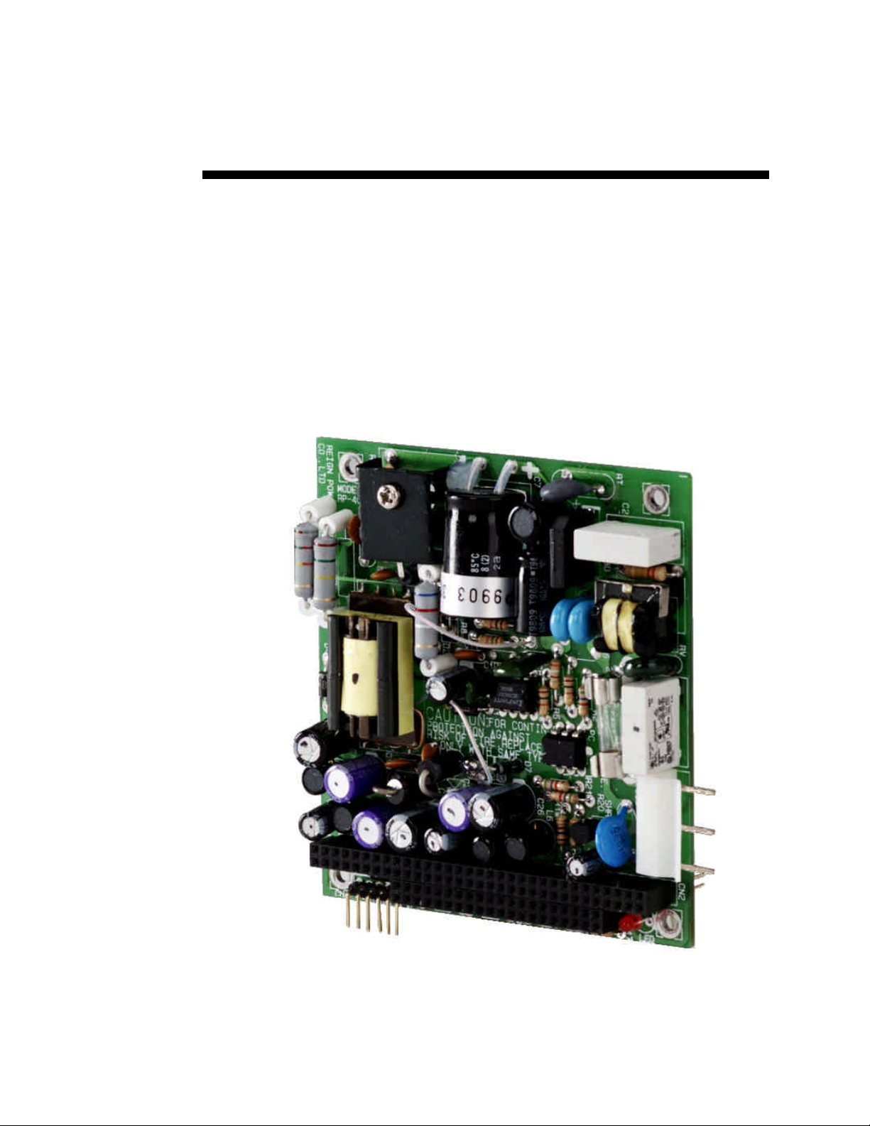
The Smart Trac PS (Power Supply) card supplies power to the Smart Trac CPU
card and all of the Smart Trac option cards. The Smart Trac PS card requires
input power as a single phase voltage from 90 to 264 VAC. The output power is
+5 VDC at 2000 mA, -5 VDC at 200mA, +12 VDC at 1000 mA, and -12 VDC
at 300mA. The power is output through a PC/104 connector. The card complies
with the PC/104 Specification, Version 2.1.
SMART TRAC PS Card
Specifications
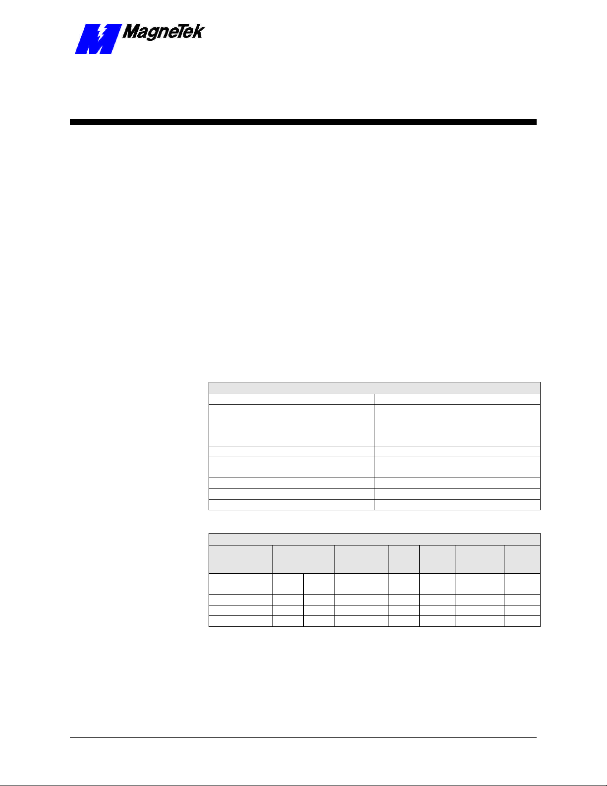
Smart Trac PS Card Specifications
Input Voltage 90-264 VAC
Output voltage +5 V @ 2A
-5 V @ 0.2 A
+12 V @ 1 A
-12 V @ 0.3A
Input frequency 47-63 Hz
Inrush current (cold) 20A @ 110 VAC
40A @ 220 VAC
Operation temperature 0° C -50° C
Storage temperature -20° C -80° C
Relative humidity 0 - 90%, non-condensing
Smart Trac PS Card Output Specifications
OVP
O/P Volts
+5 V ± 10% 0.4A 2A 50 mV
-5 V ± 10% 0A 0.2A 50 mV
+12 V ± 10% 0A 1A 120 mV
-12 V ± 10% 0A 0.3A 120 mV
Load Current
Min Max
Ripple
Noise Line Load Efficiency
±1% ±2% 72% min. 5.6-
p.p.
±1% ±10%
p.p.
±1% ±5%
p.p.
±1% ±10%
p.p.
Trip
Point
6.0V
Technical Manual TM 3554-0030 Smart Trac PS Card •• 3
Page 8

SMART TRAC PS Card
Quick Start
1. Remove all Smart Trac cards except the Smart Trac Inverter, CPU and
PG cards per instructions in “Installing the Smart Trac PS Card.”
2. Install the Smart Trac PS card as the fourth card of the card stack.
3. Make connections to the Smart Trac PS card connector CN1 per
information contained in this manual and your situation. (Connector
CN4 is not used except for testing).
4. Replace all other cards on top of the Smart Trac PS card per the
instructions in the “Installing the Smart Trac PS Card.”
5. Power up and test functionality of your Smart Trac AC1, including that
of the Smart Trac PS card
.
4 •• Smart Trac PS Card Technical Manual TM 3554-0030
Page 9
SMART TRAC PS Card
Installing the Smart Trac PS
Card
Unpacking
Electrostatic
Discharge (ESD)
Procedures
Unpacking Procedure
WARNING WARNING -- ESD ESD
Keep electronic circuit boards in Electrostatic Discharge (ESD)
protective bags when not being handled. Use proper ESD
procedures (including an ESD wrist strap) when handling circuit
boards. Failure to comply may result in damage to equipment.
When working with an electrostatic discharge (ESD) sensitive device, you
should be grounded at all times. The easiest and most common way to provide
this ground is to use an approved ESD wrist strap. The strap is secured to your
wrist with a wire attached to the strap and clipped or taped to the chassis of the
unit being worked on. Any static is dissipated through the wire to ground,
greatly reducing the possibility of damage to the device.
It is a good idea to touch the chassis with your finger before handling any
electrostatic sensitive device. Any static electricity will be discharged to chassis
ground and will not be transferred to the device.
Always store devices (cards, other electronic components) in ESD protective
bags when not being handled.
Remove the protective shipping and packing material from the card. Ensure
contact wedges and other shipping devices have been removed.
Installing the Smart Trac PS Card
The Smart Trac PS Card must be positioned above the Smart Trac PG Card on
the Smart Trac AC1 card stack.
NOTE: If replacing a Smart Trac PS card to an existing Smart Trac card stack,
see "Appendix C – Removing the Smart Trac Card Stack" before continuing.
Technical Manual TM 3554-0030 Installing the Smart Trac PS Card •• 5
Page 10

Smart Trac
SMART TRAC PS Card
Standoffs (4
places on top of
each card)
4CN
Connector
Optional
PC/104
Card
Optional
PC/104
Card
Smart Trac
Ethernet
Card
PS Card
Smart Trac
PG Card
2CN
Connector
Smart Trac
CPU Card
Inverter Control
Card
Adapter
Ring
Main Chassis
Figure 1. Smart Trac PS Card Stack Position
1. Orient the Smart Trac PS card above the Smart Trac PG card so that
PC/104 connector pins on the Smart Trac PS card align with the
receptacle on the Smart Trac PG card. Exercise care in handling so the
pins don’t bend when the card is pushed into place
2. Gently but firmly push the Smart Trac PS card down to mate with the
Smart Trac PG card, making sure that you keep pins in proper
alignment. Secure the card using four (4) metal standoffs.
3. Replace the Smart Trac PG Card and other cards by reversing the
instructions in "Appendix C – Removing the Smart Trac Card Stack".
6 •• Installing the Smart Trac PS Card Technical Manual TM 3554-0030
Page 11

SMART TRAC PS Card
Technical Manual TM 3554-0030 Installing the Smart Trac PS Card •• 7
Page 12

Page 13

Making Connections
Connectors
The Smart Trac PS card has three connectors: PC/104 Connector (mates with
PC/104 connector on Smart Trac PG card), AC Input Connector CN1 and DC
Output Connector CN4. The DC Output Connector CN4 is not used. See “Smart
Trac PS Card Layout” for location of connectors.
SMART TRAC PS Card
PC/104 Connector
The PC/104 Connector is a “stack-through” connector. Gold pins on the Smart
Trac PS Card mate with a PC/104 receptacle on the Smart Trac PG card. The
PC/104 connector on the Smart Trac PS card also accepts PC/104 pins from the
Smart Trac Ethernet card normally placed on top, to mate with it.
AC Input Connector CN1
The AC input connector has three pins for AC Input (L=Line, N=Neutral,
FG=Ground).
1
2
3
CN1
L (AC)
N (AC)
FG (Ground)
Technical Manual TM 3554-0030 Making Connections •• 9
Page 14

-5V
-12V
+12V
GND
GND
+5V
SMART TRAC PS Card
Smart Trac PS Card Layout
CN1
PC/104 Connector
CN4
PC/104 Connector
Fuse 2 A/250V
Pin 1
L (AC Line)
N (AC Neutral)
FG (Ground)
Pin
1
LED
Figure 2. Smart Trac PS card layout.
NOTE: CN4 is not to be used for powering external devices. The pins are
provided as test points only!
10 •• Making Connections Technical Manual TM 3554-0030
Page 15

Testing Card Installation
On-board Indicator Light (LED)
When illuminated, a red LED (light emitting diode) on the power supply card
indicates that power is being supplied to the card (see "Figure 2"). During
normal operation, this light should be ON.
SMART TRAC PS Card
Checking Input Power
To check the voltage of power to the Smart Trac PS card:
WARNINGWARNING
Take proper precautions when making the following system checks.
Hazardous voltages and amperage are present. The front door of the
Smart Trac AC1 must be open and power applied to the unit while
testing. Electrical shock or damage to the equipment may result if
precautions are not taken while testing the power supply. Failure to
comply may result in personal injury or death.
1. Connect one lead of a Digital Voltmeter or Digital Multimeter to AC
Line pin L of CN1. Connect the other to pin N of CN1.
2. Read the AC Line voltage and record. It should be +90 to 264 VAC,
depending on the source of power to it.
Technical Manual TM 3554-0030 Testing Card Installation •• 11
Page 16

SMART TRAC PS Card
Checking the Power Supply Output
1. Tag the Smart Trac AC1 "Out of Service."
WARNINGWARNING
Take proper precautions when making the following system checks.
2. Open the door to the Smart Trac AC1. Do not touch components inside
3. Connect one lead of a digital multimeter to the common on the CN4
4. Read the multimeter. The +5V pin should read +4.5 volts to +5.5 volts.
Hazardous voltages and amperage are present. The front door of the
Smart Trac AC1 must be open and power applied to the unit while
testing. Electrical shock or damage to the equipment may result if
precautions are not taken while testing the power supply. Failure to
comply may result in personal injury or death.
unit.
connector and the other lead to either +5V or +12V pins.
The +12V pin should read +10.8 volts to +13.2 volts. If out of range,
replace the Smart Trac PS card.
NOTE: Negative pin (–5V or –12V) readings depend on your specific Smart
Trac AC1 system configuration and will typically deviate considerably (more
negative) from their –5V or –12V labels. Only the positive pins will give
consistent results system-to-system.
5. Close the door to the Smart Trac AC1.
6. Remove "Out of Service" tags.
7. Test operation of Smart Trac AC1.
12 •• Testing Card Installation Technical Manual TM 3554-0030
Page 17

SMART TRAC PS Card
Appendix A - Maintenance and
Replaceable Parts List
Maintenance
A 2 amp, 250 volt fast type fuse protects your Smart Trac PS card. It may be
replaced as required. For location, see Figure 2.
Replaceable Parts List
The only replaceable part on the Smart Trac PS card is listed below. See the
Smart Trac AC1 Technical Manual for other replacement parts, optional parts
and tools, ordering contacts and procedures.
MagneTek
Description
Smart Trac PS Card 46S03554-0030 1
Technical Manual – Smart Trac PS Card TM 3554-0030 1
Fuse, 2 amp, 250 volt, fast type 1 req'd
Standoff, 4.5mm, Hex, Stl, CL ZINC, 15mm,
M/F, M3, M3
Card Extraction Tool (Parvus
Tools Kit TBD Option
Part Number Qty
05P00618-0006 4 each PS
assy.
Option
Corporation P/N
PRV-0760A-01)
Technical Manual TM 3554-0030 Appendix A - Maintenance and Replaceable Parts List •• 13
Page 18

SMART TRAC PS Card
THIS PAGE INTENTIONALLY LEFT BLANK
14 •• Appendix A - Maintenance and Replaceable Parts List Technical Manual TM 3554-0030
Page 19

SMART TRAC PS Card
Appendix B - Technical Support
Getting Help
Should you need technical assistance with installation or troubleshooting of your
Smart Trac AC1, you can phone our Help Desk at either (800)-541-0939 or
(262)-782-0200. Alternatively, you may copy the Problem Report form, found
on the next page, and fax it to us at (262)-782-3418.
References
MagneTek Drives and
Systems
PC/104 Specification,
Version 2.1
For more information about MagneTek drives
and systems, training programs and contacts,
visit:
http://www.magnetekdrives.com
PC/104 Consortium. An overview and the
specification may be obtained at the web site
address:
http://www.controlled.com/pc104/index.html
Technical Manual TM 3554-0030 Appendix B - Technical Support •• 15
Page 20

SMART TRAC PS Card
Problem Report
Name:
Address:
City: State: Zip
Serial Number: Power Supply Card
Occurrence: Frequently Intermittantly Rarely
Nature of Problem:
Conditions when problem occurs:
16 •• Appendix B - Technical Support Technical Manual TM 3554-0030
Page 21

SMART TRAC PS Card
Appendix C – Removing the
Smart Trac Card Stack
General Procedures
1. Power off the Smart Trac AC1. Disconnect it and tag "Out of Service".
2. Do one of the following:
• Open the cover to the Smart Trac AC1 by rotating the spring-
loaded, captive screw counterclockwise. Use a large screwdriver if
necessary to free the slotted screw.
OR
• Loosen the screws holding down the cover.
3. Disconnect the 12-pin wiring harness from connector J4 at the digital
operator.
4. Using the Phillips head screwdriver, remove the ground strap from the
left inside and the ground strap from the top inside of the Smart Trac
AC1 adapter ring.
5. Disconnect the 9-pin RS-232 cable at connector J5 on the Smart Trac
CPU card.
Technical Manual TM 3554-0030 Appendix C – Removing the Smart Trac Card Stack •• 17
Page 22

chassis
board
SMART TRAC PS Card
12-pin wiring
harness on
Digital Operator
attached to
connector J4 on
Smart Trac
CPU Card
Digital
Operator
9-pin RS-232
cable
attached here
4mm screws
(4 places)
secure ring
to main
Standoffs (4
places)
secure each
board
Smart Trac
Board Stack
PC/104
9-pin RS-232
cable
connector J5
6. Using a 4.5mm hex head driver, remove four standoffs from the
topmost card.
7. Using the PC/104 extraction tool, remove the topmost card from the
stack.
Position
rectangular
"jacks"
around
edges of
PCBs
Squeeze to lift
cards apart
Figure 3. Using the PC/104 Extraction Tool.
8. Repeat step 8 above until all PC/104 cards have been removed.
9. To remove the Smart Trac PG card:
• Disconnect the 4CN connector on the PG card.
• Using a tubular extraction tool or pliers, squeeze the plastic,
spring-loaded retainer built-in to the long plastic standoff located
at the top of the PG card, just above connector J6.
• Using a PC/104 extraction tool, remove the card.
NOTE: The Smart Trac PG card requires unique handling. Wedge the extracting
tool between the PG card and the CPU card. The area between the terminal strip
on the CPU card and the serial numbered edge of the PG card can be lifted first,
then the opposite side (nearest TB1) on the PG card). Alternate sides until the
card is free of the CPU card.
10. To remove the Smart Trac CPU card:
18 •• Appendix C – Removing the Smart Trac Card Stack Technical Manual TM 3554-0030
Page 23

SMART TRAC PS Card
• Disconnect the card at the 2CN connector on the CPU card.
• The CPU card is secured with three plastic standoffs with spring-
loaded clips on the end. Squeeze the top of the standoffs (the clips)
with the special cylindrical removal tool, your fingers or needlenosed pliers and lift the CPU card from the Smart Trac Inverter
Control Card.
You have removed the entire card stack. The inverter card, considered part of
the drive, is in clear view.
Technical Manual TM 3554-0030 Appendix C – Removing the Smart Trac Card Stack •• 19
Page 24

Page 25

Glossary of Terms
SMART TRAC PS Card
Ethernet
PC/104
stack-through
The most common type of corporate network, ethernet is an open network
standard (per Ethernet 802.3). It was developed jointly by Intel, Digital (now
Compaq) and Xerox). An Ethernet card is standard in a Smart Trac AC1.
An embedded PC bus standa4rd. The standard defines the mechanical size of a
self-stacking bus. Also an IEEE draft standard, called the P996.1 Standard for
Compact Embedded PC Modules, the PC/104 Specification, Version 2.1, July
1994, PC/104 Consortium.
Used to describe a connector with pins on one side of a printed circuit board and
a receptacle for pins on the other side. With such a connector, one board may be
mated electrically to another board, yet be layered, one on top of anohter, as part
of a board stack.
Technical Manual TM 3554-0030 Glossary of Terms •• 21
Page 26

SMART TRAC PS Card
THIS PAGE INTENTIONALLY LEFT BLANK
22 •• Glossary of Terms Technical Manual TM 3554-0030
Page 27

SMART TRAC PS Card
Index
A
adapter ring 7
C
Capabilities 3
card, Smart Trac CPU 7
card, Smart Trac option 7
CN1 4, 9, 11
CN4 4, 9, 12
connector
CN1 4, 9, 11
CN4 4, 9, 12
J4 6
J5 7
E
Electrostatic Discharge 1–2, 1–2, 5
extraction tool 7
G
M
menu 5, 7, 9
O
Online Help 5, 7, 9
output power 3
P
Parts 13
PC/104 3, 7–9, 7–9, 15
PG card, Smart Trac 4
power
input 3, 11
output 3
Power Supply 5, 7, 9
Problem Report 5, 7, 9
PS card, Smart Trac 1–12, 1–12, 13
PS Card, Smart Trac
layout 10
ground 5, 7, 9
W
H
Help Desk 15
warranty 2
I
information, safety 5, 7, 9
input power 3, 11
Inverter 4
L
LEDs 11
Technical Manual TM 3554-0030 Index •• 23
Page 28

SMART TRAC PS Card
Data subject to change without notice. Smart Trac is a trademark of MagneTek, Inc. MicroTrac is a registered trademark of MagneTek, Inc. Microsoft, Windows and Windows NT are registered
trademarks of Microsoft Corporation
MagneTek
Drives and Systems
16555 West Ryerson Road
New Berlin, WI 53151
(800) 541-0939, (262) 782-0200, FAX (262) 782-3418
TM 3554-0030 © 1999-2000 MagneTek, Inc. 1/31/2000
 Loading...