

Page 1
S
S
M
M
A
A
R
R
T
T
P
P
Technical Manual
™
™
T
R
A
T
R
G
G
A
C
C
C
C
arr
a
d
d
Page 2

Page 3

SMART TRAC PG Card
Table of Contents
Important Safety and Warranty Information 1
Warnings, Cautions and Notes.....................................................................................................................1
General Safety Precautions - Warnings ......................................................................................................2
Important Warranty Information................................................................................................................2
Smart Trac PG Card 3
General Capabilities......................................................................................................................................3
Closed-loop Control..........................................................................................................................3
Position Control ................................................................................................................................3
Digital Input......................................................................................................................................3
Analog Input .....................................................................................................................................3
Quick Start.....................................................................................................................................................4
Installing the Smart Trac PG Card 7
Unpacking ......................................................................................................................................................7
ElectroStatic Discharge (ESD) Procedures.......................................................................................7
Unpacking Procedure........................................................................................................................7
Installing the Smart Trac PG Card .............................................................................................................7
Using the Smart Trac PG Card 11
Basic Features..............................................................................................................................................11
Port Address ................................................................................................................................................11
Encoders.......................................................................................................................................................12
Digital Inputs ...............................................................................................................................................12
Analog Inputs...............................................................................................................................................12
Testing Card Installation 15
Test Points....................................................................................................................................................15
Checking Analog Input Signals..................................................................................................................16
Checking the Power Supply........................................................................................................................16
Checking Encoder Pulses............................................................................................................................16
Checking Pulses at Input to Smart Trac PG Card...................................................................................17
Checking Pulses at a MagneTek VCM Motor ..........................................................................................18
Troubleshooting Your Smart Trac PG Card 19
Symptoms and Corrective Action..............................................................................................................19
Appendix A – Specifications 21
Smart Trac PG Card Specifications ..........................................................................................................21
Technical Manual TM 3554-0020 Table of Contents •• i
Page 4

SMART TRAC PG Card
Appendix B - Card Layout 25
Smart Trac PG Card – Component Side...................................................................................................25
Smart Trac PG Card – Solder Side ...........................................................................................................26
Appendix C - Connections 29
Feedback Encoder Input (J3).....................................................................................................................29
Logic Input (J4)...........................................................................................................................................29
Follower Encoder Input (J5) ......................................................................................................................30
Monitor Output (J6)....................................................................................................................................30
Analog Channel 0 (J9).................................................................................................................................30
Analog Channel 1 (J10)...............................................................................................................................31
Shield Termination (J11)............................................................................................................................31
Shield Termination (J12)............................................................................................................................31
Appendix D – Removing the Smart Trac Card Stack 35
General Procedures.....................................................................................................................................35
Appendix E – Technical Support 39
Getting Help.................................................................................................................................................39
References ....................................................................................................................................................39
Problem Report ...........................................................................................................................................40
Appendix F – Replaceable Parts Listing 41
Replaceable Parts Listing ...........................................................................................................................41
Glossary of Terms 43
Index 45
ii •• Table of Contents Technical Manual TM 3554-0020
Page 5
SMART TRAC PG Card
Important Safety and Warranty
Information
Warnings, Cautions and Notes
WARNING
A statement of conditions which MUST BE OBSERVED to
prevent personal injury or death.
WARNING - ESD
A statement of conditions which must be observed to prevent
damage to components due to ESD (ElectroStatic Discharge) and
to prevent personal injury or death.
CAUTION
A statement of conditions which must be observed to prevent
undesired equipment faults, Smart Trac AC1 system degradation
and damage to equipment.
IMPORTANT
A statement of conditions which should be observed during Smart Trac AC
DeviceNet setup or operation to ensure dependable service.
NOTE: Notes indicate information that is in addition to a discussion of the topic
in adjoining text. Alternatively, it may limit or restrict the paragraph(s) that
follow(s) to specific models or conditions.
Technical Manual TM 3554-0020 Important Safety and Warranty Information •• 1
Page 6
SMART TRAC PG Card
TIP - Tips indicate information that should make a procedure easier or more
efficient.
General Safety Precautions Warnings
Important safety information follows. Please read and understand all
precautions listed below before proceeding with the specification, installation,
set-up or operation of your Smart Trac AC1. Failure to follow any of the
following precautions may result in personal injury or death, or damage to the
equipment.
WARNING - ESD
The Control Printed Circuit Board (PCB) employs CMOS
Integrated Circuits that are easily damaged by static electricity.
Use proper ElectroStatic Discharge (ESD) procedures when
handling the Control PCB. See Smart Trac AC1 Technical Manual
for details. Failure to comply may result in damage to equipment
and/or personal injury.
Important Warranty Information.
Do not modify your Smart Trac AC1, its components, or any of the procedures
contained in the technical documentation supplied by MagneTek. Any
modification of this product by the user is not the responsibility of MagneTek
and will void the warranty.
2 •• Important Safety and Warranty Information Technical Manual TM 3554-0020
Page 7

Smart Trac PG Card
General Capabilities
SMART TRAC PG Card
Closed-loop Control
Position Control
Digital Input
Analog Input
A Smart Trac PG Card added to your Smart Trac AC1 provides closed loop flux
vector control and closed loop speed control. With the card, 5 V to 12 V
differential quadrature signals at a rate of up to 300 KHz with a 540 ohm input
load may be input. Quadrature phasing of encoder inputs is 90 degrees +/- 22
degrees maximum at 300 kHz. Follower applications may use a second encoder
input. A 12 VDC power supply rated at 200 mA supplies power to the encoder.
The Smart Trac PG Card also provides position control. Start and stop signals
control two 32-bit counters that can be used to measure the rotation of either
start or stop signals. The Start and Stop signals can come from one of three
sources: the marker pulse of either encoder; one of the two digital inputs (i.e.,
connected to proximity switches); or software command.
The two 12 VDC input signals can be used as general purpose inputs if not
needed for position control.
Two analog input channels can accommodate either load cells or potentiometers.
The input voltage range for each channel is ± 600 mV or ± 10 Volts, selectable.
The Smart Trac PG Card also supplies:
• an A/D converter with 12 bits of resolution.
• a +5VDC, 50 mA power supply.
• reference voltages of +10VDC and -10VDC, both rated at 10 mA.
Quick Start
1. Remove all Smart Trac cards except the Smart Trac Inverter and CPU
cards per instructions in "Installing the Smart Trac PG Card. "
2. Install the Smart Trac PG card as the second card of the card stack.
3. Make connections to the PG card terminal blocks per information
contained in this manual and your situation.
4. Replace all other cards per the instructions in "Installing the Smart Trac
PG Card."
5. Power up and test functionality of your Smart Trac AC1, including that
of the Smart Trac PG card.
Technical Manual TM 3554-0020 Smart Trac PG Card •• 3
Page 8

SMART TRAC PG Card
THIS PAGE INTENTIONALLY LEFT BLANK
4 •• Smart Trac PG Card Technical Manual TM 3554-0020
Page 9

SMART TRAC PG Card
Installing the Smart Trac PG
Card
Unpacking
ElectroStatic
Discharge (ESD)
Procedures
Unpacking Procedure
WARNING WARNING -- ESD ESD
Keep electronic circuit boards in ElectroStatic Discharge (ESD)
protective bags when not being handled. Use proper ESD
procedures (including an ESD wrist strap) when handling circuit
boards. Failure to comply may result in damage to equipment.
When working with an ElectroStatic Discharge (ESD) sensitive device, you
should be grounded at all times. The easiest and most common way to provide
this ground is to use an approved ESD wrist strap. The strap is secured to your
wrist with a wire attached to the strap and clipped or taped to the chassis of the
unit being worked on. Any static is dissipated through the wire to ground,
greatly reducing the possibility of damage to the device.
It is a good idea to touch the chassis with your finger before handling any
electrostatic device. Any static electricity will be discharged to chassis ground
and will not be transferred to the device.
Always store devices (cards, other electronic components) in ESD protective
bags when not being handled.
Remove the protective shipping and packing material from the card. Ensure
contact wedges and other shipping devices have been removed.
Installing the Smart Trac PG Card
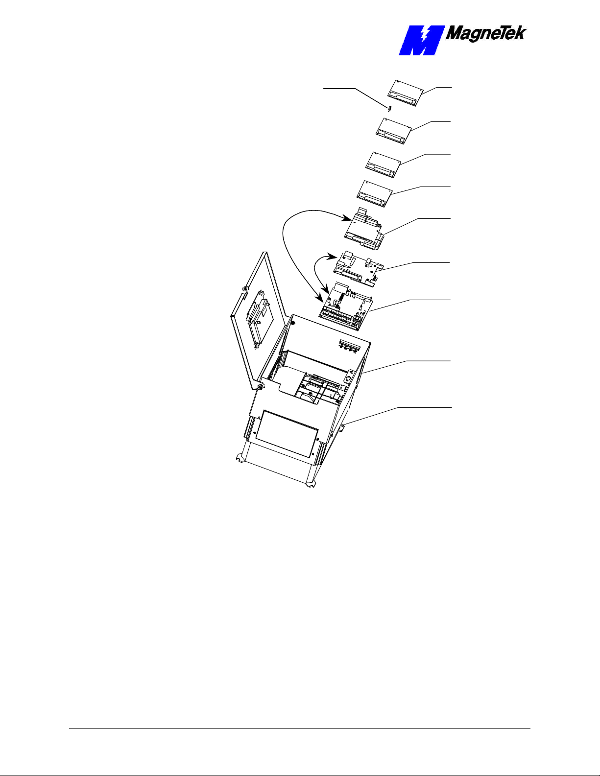
The Smart Trac PG Card must be positioned above the Smart Trac CPU card on
the Smart Trac AC1 card stack.
NOTE: If replacing or adding a Smart Trac PG card to an existing Smart Trac
card stack, see Appendix D – "Removing the Smart Trac Card Stack" before
continuing.
Technical Manual TM 3554-0020 Installing the Smart Trac PG Card •• 5
Page 10
Card
SMART TRAC PG Card
Standoffs (4
places on top of
each card)
4CN
Connector
2CN
Connector
Smart Trac
Genius PCIM
Card
Optional
PC/104
Card
Smart Trac
Ethernet
Smart Trac
PS Card
Smart Trac
PG Card
Smart Trac
CPU Card
Inverter Control
Card
Adapter
Ring
Main Chassis
Figure 1. Smart Trac PG Card Stack Position
1. Power off the Smart Trac AC1. Disconnect it and tag it as "Out of
Service". Perform this and all other steps required to remove all cards
located in a stack position above the PG Card. See "Appendix D –
Removing the Smart Trac Card Stack"
2. To replace the PG card, orient the PG card so that the PC/104
connector and the J2 connector align with the PC/104 connector on the
Smart Trac CPU card and the 4CN connector on the Inverter Control
board. Be careful to align the PC/104 connector pins with the
receptacle on the Smart Trac CPU card so the pins don’t bend when the
card is pushed into place.
3. Gently but firmly push the Smart Trac PG card onto the Smart Trac
CPU card. Make sure connecting pins are in alignment and J2 mates
with 4CN before pushing the two boards tightly together. Secure the
card using four (4) metal standoffs and one (1) plastic standoff.
6 •• Installing the Smart Trac PG Card Technical Manual TM 3554-0020
Page 11

SMART TRAC PG Card
4. Replace the Smart Trac PS or Ethernet card and other cards by
reversing the procedures described in the Appendix "Removal of the
Smart Trac Card Stack."
Technical Manual TM 3554-0020 Installing the Smart Trac PG Card •• 7
Page 12

Page 13

SMART TRAC PG Card
Using the Smart Trac PG Card
Basic Features
The Smart Trac PG card has:
• Two encoder inputs for closed loop flux vector control, closed loop
speed control and position control.
• Digital inputs (if not needed for position control).
• Analog inputs to accommodate load cells or potentiometers.
Port Address
The Smart Trac PG card uses a port address of "1". Hardwired on the card, the
address may be overridden if two Smart Trac PG cards must be used. Contact
MagneTek for details.
Encoders
Connect encoders at Terminal Block J3 (feedback encoder input) or at Terminal
Block J5 (follower encoder input). Only the feedback encoder Terminal Block
J3 provides a 12 volt power supply for the encoder.
Channel 0 - feedback encoder
Use Channel 0 for the encoder of the motor connected to the Smart Trac AC1. It
provides feedback to both the Smart Trac AC1 inverter control card and CPU.
Terminal Block J3 provides these connections for differential A, B and Z inputs
and a 12-volt @200ma power supply. A and B are used for speed and position
control. Z is used for position start and stop only.
Channel 1 - follower encoder
Use Channel 1 for another feedback source. It only provides feedback for the
Smart Trac CPU card. Terminal Block J5 provides connections for differential
A, B and Z inputs.
Digital Inputs
Two +12 Volt digital inputs are located on Terminal Block J4 for proximity
switch inputs (LI0 and LI1). Each of the digital inputs sinks 10mA and may be
used for position start and stop, or as a general purpose input.
Technical Manual TM 3554-0020 Using the Smart Trac PG Card •• 9
Page 14

SMART TRAC PG Card
Analog Inputs
The Smart Trac PG card provides analog input differential pairs of 600mV and
10V at Terminals Blocks J9 (Analog Channel 0) and J10 (Analog Channel 1).
Pins 1-2 of the terminal blocks are inputs for the 600 mV pair. Pins 3-4 of the
terminal blocks are inputs for the 10V pair.
10 •• Using the Smart Trac PG Card Technical Manual TM 3554-0020
Page 15

Testing Card Installation
Test Points
You may test the Smart Trac PG card at eleven test points. The test points and a
description of each follows:
SMART TRAC PG Card
Smart Trac PG Card Test Points
Test Point
Designator Description Purpose
TP1 Analog Common Test analog input signals
TP9 Analog Input 0 Test analog input signals
TP10 Analog Input 1 Test analog input signals
TP2 Digital Common Test encoder test points
TP3 A pulse, encoder channel 0 Test pulse after Smart Trac PG card
TP4 B pulse, encoder channel 0 Test pulse after Smart Trac PG card
TP5 Z pulse, encoder channel 0 Test pulse after Smart Trac PG card
TP6 A pulse, encoder channel 1 Test pulse after Smart Trac PG card
TP7 B pulse, encoder channel 1 Test pulse after Smart Trac PG card
TP8 Z pulse, encoder channel 1 Test pulse after Smart Trac PG card
TP11 +5 V Isolated Common Test pulses at input to Smart Trac PG
TP12 Inverter Digital Common Field Service use only
card
Checking Analog Input Signals
You may check analog inputs using a Digital Voltmeter or Multimeter between
test points TP1 (common) and either TP9 (Analog Input 0) or TP10 (Analog
Input 1). Values should be within a range of –10V to +10V.
Technical Manual TM 3554-0020 Testing Card Installation •• 11
Page 16

SMART TRAC PG Card
Checking the Power Supply
You may check the +5V power supply by connecting a Digital Voltmeter or
Digital Multimeter between J9-6 (5V power supply) and J9-7 (5V power supply
return). It should read between 4.5 and 5.5 volts.
Checking Encoder Pulses
Using an oscilloscope, you can check encoder pulses after they have been
processed by the Smart Trac PG card or at the motor.
Note: Measure all encoder pulses at the input with reference to +5V isolated
common (TP11).
WARNINGWARNING
Take proper precautions when making the following system
checks. Hazardous voltages and amperage are present. The front
door of the Smart Trac AC1 must be open and power applied to
the unit while testing. Electrical shock or damage to the equipment
may result if precautions are not taken while checking encoder
pulses. Failure to comply may result in personal injury or death.
1. Remove power from L1, L2 and L3. Wait for the CHARGE light to go
out.
2. Connect the common of the oscilloscope to TP2 (digital) to check
encoder signals.
NOTE: You may want to remove the adapter ring from the drive for easier
access to test points, especially when testing drives with smaller case sizes (1-4).
3. Connect one channel of the oscilloscope to TP3 if checking channel 0
or TP6 if checking channel 1. If using a two-channel oscilloscope,
connect the second channel to TP4 if checking channel 0 or TP7 if
checking channel 1.
4. Set the oscilloscope for 2V/div, 50ms/div, normal trigger, and rising
edge trigger.
5. Apply power to the Smart Trac AC1, but DO NOT apply a RUN
command.
6. Turn the motor shaft by hand. You should see pulses on both channels
at a +5V level, 50% duty cycle. The pulses should be separated by 90
electrical degrees (half a pulse).
7. If one or both channels do not have the correct pulses present (i.e.
missing pulses, incorrect duty cycle, improper voltage, etc.) check
pulses at input to the Smart Trac PG card (next procedure).
12 •• Testing Card Installation Technical Manual TM 3554-0020
Page 17

SMART TRAC PG Card
Checking Pulses at Input to Smart
Trac PG Card
NOTE: The following procedure describes checking feedback (channel 0)
encoder pulses at terminal J3 and follower (channel 1) encoder pulses at
terminal J5.
1. Remove power from L1, L2 and L3. Wait for the CHARGE light to go
out.
2. Connect the common of the oscilloscope to TP11 (+5 V ISO Common).
NOTE: This procedure requires a two-channel oscilloscope to view the
relationship between A+ and A- at the same time.
3. To check A to /A: Connect one channel of the oscilloscope to J3-1 if
checking channel 0 A pulse or J5-1 if checking channel 1 A pulse.
Connect the second channel to J3-2 (/A pulse) if checking channel 0 or
J5-2 (/A pulse) if checking channel 1.
4. Set the oscilloscope for 5V/div, 50ms/div, normal trigger, and rising
edge trigger.
5. Apply power to the Smart Trac AC1, but DO NOT apply a RUN
command.
6. Turn the motor shaft by hand. You should see pulses on both channels
and 50% duty cycle. The pulses should be separated by 180 electrical
degrees (one the inverse of the other).
7. Disconnect the two oscilloscope channels. Reconnect them to terminals
J3-3 or J5-3 (B pulse) and J3-4 or J5-4 (/B pulse).
8. To check B to /B: Turn the motor shaft by hand. You should see pulses
on both channels and 50% duty cycle. Again, the pulses should be
separated by 180 electrical degrees (one the inverse of the other).
9. To check A to B, Channel 0: Disconnect the two oscilloscope channels.
Reconnect them to terminals J3-1 (Channel 0 A pulse) and J3-3
(channel 0 B pulse) Check the relationship between A and B. They
should be 90 degrees out of phase.
10. To check A to B, Channel 1: Disconnect the two oscilloscope channels.
Reconnect them to terminals J5-1 (Channel 1 A pulse) and J5-3
(channel 1 B pulse) Check the relationship between A and B. They
should be 90 degrees out of phase.
11. If one or both channels do not have the correct pulses present (i.e.
missing pulses, incorrect duty cycle, improper voltage, etc.), check
pulses at the motor (next procedure).
Technical Manual TM 3554-0020 Testing Card Installation •• 13
Page 18

SMART TRAC PG Card
Checking Pulses at a MagneTek VCM
Motor
1. Remove power from L1, L2 and L3. Wait for the CHARGE light to go
out.
2. Take apart the military-style, circular connector at the motor.
3. Connect the common of the oscilloscope to pin F of the circular
connector.
4. Connect one channel of the scope to pin A of the circular connector. If
the oscilloscope is two channel, connect the second channel to pin H.
5. Set the oscilloscope for 5V/div, 50ms/div, normal trigger, and rising
edge trigger.
6. Apply power to the Smart Trac AC1, but DO NOT apply a RUN
command.
7. Turn the motor shaft by hand. You should see pulses on both channels
and 50% duty cycle. The pulses should be separated by 180 electrical
degrees (one the inverse of the other).
If no pulse can be seen on any of the four connector pins (A, B, H or I), check
the power supply between pins D and F. It should be at or near 12 VDC. If not,
check the power supply at the Smart Trac PG card, between J3-7 and J3-8. If the
power supply is not at or near 12VDC, check to make sure J2 is mated with 4CN
on the inverter control board. If it is properly mated, replace the Smart Trac PG
card.
14 •• Testing Card Installation Technical Manual TM 3554-0020
Page 19

SMART TRAC PG Card
Troubleshooting Your Smart
Trac PG Card
Symptoms and Corrective Action
Many problems associated with the functioning of the Smart Trac PG card will
be discovered when troubleshooting the Smart Trac AC1 and its option boards
as an integrated unit. They are listed in the following table along with symptoms
unique to the Smart Trac PG card.
Smart Trac PG Card Symptoms and Corrective Action
Symptoms Probable Cause Corrective Action
Smart Trac PG
Card not
functioning
PG cable wires not installed. Install cable wires.
No encoder pulses
- Smart Trac PG
card installed and
good cable wires
and connections.
Motor does not
rotate
Motor does not
rotate at set speed.
Control method set to Flux
Vector or V/F w/PG but no
PG card installed.
Defective Smart Trac PG
card
Improper connections from
PG
Out of tolerance or no PG
output signal if Flux Vector
or V/F w/PG control
Install Smart Trac PG card.
Check pulses per chapter "Testing
Card Installation." Replace Smart
Trac PG card as required.
Repair or replace connecting
cables.
Replace Smart Trac PG card
PG power supply. Replace power supply.
Technical Manual TM 3554-0020 Troubleshooting Your Smart Trac PG Card •• 15
Page 20

SMART TRAC PG Card
Symptoms Probable Cause Corrective Action
Smart Trac PG Card Symptoms and Corrective Action
Motor hunting
Motor Overload
fault indication
Heatsink Overtemp
fault indication.
Bad or no connections from
inverter control board to PG
card if Flux Vector or V/F
w/PG control.
PG PCB may be faulty.
May be faulty or defective
Smart Trac PG.
Check connections from Inverter
Control board to PG. Repair or
replace, as necessary.
Replace Smart Trac PG card.
Replace Smart Trac PG
16 •• Troubleshooting Your Smart Trac PG Card Technical Manual TM 3554-0020
Page 21

SMART TRAC PG Card
Appendix A – Specifications
Smart Trac PG Card Specifications
Smart Trac PG Card Specifications
Analog Inputs
Digital Inputs
Feedback Encoder
Input
Follower Encoder
Input
Description Two non-isolated differential inputs,
simultaneously sampled
Voltage ± 600 mVDC or ± 10VDC
Input Impedence > 100,000 ohms
Resolution 12 bits
Description Two, opto-isolated
Voltage 12 VDC internal pull-up provided
Sink Current 10 mA
Frequency 10KHz maximum
Pulse Width 0.1 ms minimum
Supply Voltage 12 VDC @ 200mA
Maximum Frequency 300 kHz
Input Differential quadrature, opto-isolated
(A, /A, B, /B)
Optional differential index , opto-
isolated (Z, /Z)
540 ohm input load on each pair
5 to 12 VDC differential input voltage
Quadrature Phasing: 90 degrees +/-
22 degrees max. at 300 KHz.
Maximum Frequency 300 kHz
Technical Manual TM 3554-0020 Appendix A – Specifications •• 17
Page 22

SMART TRAC PG Card
Smart Trac PG Card Specifications
Follower Encoder
Input
Encoder Monitor
Output
Reference Voltage
Outputs
Isolated Power
Supply Output
Input Differential quadrature, opto-isolated
(A,/ A, B, /B)
Optional differential index, opto-
isolated (Z, /Z)
540 ohm input load on each pair
5 to 12 VDC differential input voltage.
Quadrature Phasing: 90 degrees +/-
22 degrees max. at 300 KHz.
Description Quadrature plus index, opto-isolated
(A, /A, B, /B, Z, /Z)
Outputs RS-422 differential
Source Software selectable
+ 10 VDC @ 10mA
- 10 VDC @ 10mA
+ 5 VDC @ 50mA
18 •• Appendix A – Specifications Technical Manual TM 3554-0020
Page 23

SMART TRAC PG Card
Appendix B - Card Layout
Smart Trac PG Card – Component
Side
TP3
TP4
TP5
TP2
TP6
TP7
TP8
Common
J6
J3 J5
A
B
Z
Encoder 0
A
B
Z
Encoder 1
=
Pin 1
J12
J4
J10
PC/104 Receptacle
PC/104 Receptacle
J11
Top (Component) Side
J9
Technical Manual TM 3554-0020 Appendix B - Card Layout •• 19
Page 24

SMART TRAC PG Card
Smart Trac PG Card – Solder Side
J10
Connector
4CN
J4
J9
PC/104 Connector pins
PC/104 Connector pins
(Back Side)
20 •• Appendix B - Card Layout Technical Manual TM 3554-0020
Page 25

SMART TRAC PG Card
Appendix C - Connections
Feedback Encoder Input (J3)
1
2
3
4
5
6
7
8
J3
Encoder 0 A+
Encoder 0 AEncoder 0 B+
Encoder 0 BEncoder 0 Z+
Encoder 0 ZEncoder 12 VDC
Encoder RTN
Logic Input (J4)
1
2
3
4
J4
Logic Input (LI0)
Common for LI0
Logic Input (LI1)
Common for LI1
Follower Encoder Input (J5)
1
2
3
4
5
6
J5
Technical Manual TM 3554-0020 Appendix C - Connections •• 21
Encoder 1 A+
Encoder 1 AEncoder 1 B+
Encoder 1 BEncoder 1 Z+
Encoder 1 Z-
Page 26

SMART TRAC PG Card
Monitor Output (J6)
1
2
3
4
5
6
J6
Monitor A+
Monitor AMonitor B+
Monitor BMonitor Z+
Monitor Z-
Analog Channel 0 (J9)
1
2
3
4
5
6
7
8
J9
Analog Input 1 600 mV +
Analog Input 1 600 mV Analog Input 0 10 V +
Analog Input 0 10 V Analog Common
5 Volt power supply
5 Volt power supply return
Not Used
Analog Channel 1 (J10)
1
2
3
4
5
6
7
8
J10
Analog Input 1 600 mV +
Analog Input 1 600 mV Analog Input 1 10 V +
Analog Input 1 10 V -
Analog Common
+10 Volt Reference
Not Used
-10 Volt Reference
Shield Termination (J11)
1
2
3
4
5
6
Terminating Shield
Terminating Shield
Terminating Shield
Terminating Shield
Terminating Shield
Terminating Shield
J11
22 •• Appendix C - Connections Technical Manual TM 3554-0020
Page 27

SMART TRAC PG Card
Shield Termination (J12)
1
2
3
J12
Terminating Shield
Terminating Shield
Terminating Shield
Technical Manual TM 3554-0020 Appendix C - Connections •• 23
Page 28

SMART TRAC PG Card
THIS PAGE INTENTIONALLY LEFT BLANK
24 •• Appendix C - Connections Technical Manual TM 3554-0020
Page 29

SMART TRAC PG Card
Appendix D – Removing the
Smart Trac Card Stack
General Procedures
1. Power off the Smart Trac AC1. Disconnect it and tag "Out of Service".
2. Do one of the following:
• Open the cover to the Smart Trac AC1 by rotating the spring-
loaded, captive screw counterclockwise. Use a large screwdriver if
necessary to free the slotted screw.
OR
• Loosen the screws holding down the cover.
3. Disconnect the 12-pin wiring harness from connector J4 at the digital
operator.
4. Using the Phillips head screwdriver, remove the ground strap from the
left inside and the ground strap from the top inside of the Smart Trac
AC1 adapter ring.
5. Disconnect the 9-pin RS-232 cable at connector J5 on the Smart Trac
CPU card.
Technical Manual TM 3554-0020 Appendix D – Removing the Smart Trac Card Stack •• 25
Page 30

chassis
board
SMART TRAC PG Card
12-pin wiring
harness on
Digital Operator
attached to
connector J4 on
Smart Trac
CPU Card
Digital
Operator
9-pin RS-232
cable
attached here
4mm screws
(4 places)
secure ring
to main
Standoffs (4
places)
secure each
board
Smart Trac
Board Stack
PC/104
9-pin RS-232
cable
connector J5
6. Using a 4.5mm hex head driver, remove four standoffs from the
topmost card.
7. Using the PC/104 extraction tool, remove the topmost card from the
stack.
Position
rectangular
"jacks"
around
edges of
PCBs
Squeeze to lift
cards apart
Figure 2. Using the PC/104 Extraction Tool.
8. Repeat step 8 above until all PC/104 cards have been removed.
9. To remove the Smart Trac PG card:
• Disconnect the 4CN connector on the PG card.
• Using a tubular extraction tool or pliers, squeeze the plastic,
spring-loaded retainer built-in to the long plastic standoff located
at the top of the PG card, just above connector J6.
• Using a PC/104 extraction tool, remove the card.
NOTE: The Smart Trac PG card requires unique handling. Wedge the extracting
tool between the PG card and the CPU card. The area between the terminal strip
on the CPU card and the serial numbered edge of the PG card can be lifted first,
then the opposite side (nearest TB1) on the PG card). Alternate sides until the
card is free of the CPU card.
10. To remove the Smart Trac CPU card:
26 •• Appendix D – Removing the Smart Trac Card Stack Technical Manual TM 3554-0020
Page 31

SMART TRAC PG Card
• Disconnect the card at the 2CN connector on the CPU card.
• The CPU card is secured with three plastic standoffs with spring-
loaded clips on the end. Squeeze the top of the standoffs (the clips)
with the special cylindrical removal tool, your fingers or needlenosed pliers and lift the CPU card from the Smart Trac Inverter
Control Card.
You have removed the entire card stack. The inverter card, considered part of
the drive, is in clear view.
Technical Manual TM 3554-0020 Appendix D – Removing the Smart Trac Card Stack •• 27
Page 32

Page 33

SMART TRAC PG Card
Appendix E – Technical Support
Getting Help
Should you need technical assistance with installation or troubleshooting of your
Smart Trac AC1, you can phone our Help Desk at either (800)-541-0939 or
(262)-782-0200. Alternatively, you may copy the Problem Report form, found
on the next page, and fax it to us at (262)-782-3418.
References
MagneTek Drives and
Systems
PC/104 Specification,
Version 2.1
For more information about MagneTek drives
and systems, training programs and contacts,
visit:
http://www.magnetekdrives.com
PC/104 Consortium. An overview and the
specification may be obtained at the web site
address:
http://www.controlled.com/pc104/index.html
Technical Manual TM 3554-0020 Appendix E – Technical Support •• 29
Page 34

SMART TRAC PG Card
Problem Report
Name:
Address:
City: State: Zip
Serial Number: Smart Trac PG Card
Occurrence: Frequently Intermittantly Rarely
Nature of Problem:
Conditions when problem occurs:
30 •• Appendix E – Technical Support Technical Manual TM 3554-0020
Page 35

SMART TRAC PG Card
Appendix F – Replaceable Parts
Listing
Replaceable Parts Listing
Description MagneTek Part
Number
Smart Trac PG Card option kit 46S03643-0020 1
Technical Manual – Smart Trac PG
Card
Standoff, 4.5mm, Hex, Stl, CL ZINC,
16mm, M/F, M3, M3
Card Extraction Tool (Parvus Corporation
Hardware Tools Kit for Smart Trac
AC1
TM 3554-0020 1
05P00618-0006 4 each PG
P/N PRV-0760A-
01)
TBD Option
Qty
assy.
1
Technical Manual TM 3554-0020 Appendix F – Replaceable Parts Listing •• 31
Page 36

SMART TRAC PG Card
THIS PAGE INTENTIONALLY LEFT BLANK
32 •• Appendix F – Replaceable Parts Listing Technical Manual TM 3554-0020
Page 37

Glossary of Terms
SMART TRAC PG Card
encoder
Inverter
marker pulse
quadrature
sinks
A device that changes one digital code to another digital code.
Inverter - A device that converts Direct Current (DC) to Alternating Current
(AC).
Sometimes called an "index pulse," a marker pulse is an encoder output that
pulses once each revolution of a rotating device. Position control often employs
marker pulses to home or zero the position.
An encoder output of two channels, one of which is 90 degrees out of phase with
the other. The phase relationship changes depending on the direction of rotation.
Providing a current path to ground.
Technical Manual TM 3554-0020 Glossary of Terms •• 33
Page 38

SMART TRAC PG Card
THIS PAGE INTENTIONALLY LEFT BLANK
34 •• Glossary of Terms Technical Manual TM 3554-0020
Page 39

SMART TRAC PG Card
F
Features, Basic 9
feedback encoder 9, 17, 21
follower encoder 9, 17, 18, 21
Index
A
address,port 9
Analog Input 3, 10, 11
Analog Inputs 9, 10, 11, 17
B
block, terminal 9
C
Checking Analog Input Signals 11
Checking Encoder Pulses 12
Checking Pulses at a MagneTek
VCM Motor 14
Checking Pulses at Input to Smart
Trac PG Card 13
closed loop flux vector control 3, 9
closed loop speed control 3, 9
control
position 3, 9
speed 3, 9
control, closed-loop flux vector 3, 9
CPU 3, 9, 25
D
Digital Input 3
E
Electrostatic Sensitive Discharge 5
encoder
feedback 9, 17, 21
follower 9, 17, 18, 21
Encoder Use 9
ESD 5
ESD Procedures 2, 5
extraction tool 26
G
Getting Help 29
ground 5
H
Help Desk 29
Help, Getting 29
I
information, safety 2
Inputs
Analog 9, 10, 11, 17
Using Digital Inputs 9
Inverter 3, 6, 9, 11, 14, 16, 27
L
Layout, Smart Trac PG Card 19
load cells 3, 9
M
Monitor Output 18, 22
O
Optional Parts 31
oscilloscope 12–14, 12–14, 12–14
Output
Monitor 18, 22
P
parts
optional 31
PC/104 29
port address 9
position control 3, 9
potentiometers 3, 9
power supply 3, 9, 12, 14–15, 14–
15, 14, 18
Problem Report 29–30
proximity switches 3
pulse 3, 11–14, 11–14, 11–13
Pulses
Checking at a MagneTek VCM
Motor 14
Technical Manual TM 3554-0020 Index •• 35
Page 40

SMART TRAC PG Card
Checking at Input to Smart Trac
PG Card 13
Checking Encoder Pulses 12
W
Warranty 2
wrist strap 5
Q
quadrature 3, 17–18, 17
Quick Start 3
R
reference voltages 3
References 29
Report, Problem 29–30
S
safety information 2
Signals
Checking Analog Input Signals
11
Smart Trac PG Card – Component
Side 19
Smart Trac PG Card Specifications
17
Specifications, Smart Trac PG Card
17
static electricity 2, 5
strap
wrist 5
switches
proximity 3
Symptoms and Corrective Action
15
T
Technical Manual 2
terminal block 9
Test Points 11
tool, extraction 26
troubleshooting
Help Desk 29
Troubleshooting
Symptoms and Corrective Action
15
U
Unpacking 5
Using Digital Inputs 9
V
voltage
reference 3
36 •• Index Technical Manual TM 3554-0020
Page 41

SMART TRAC PG Card
Data subject to change without notice. Smart Trac is a trademark of MagneTek, Inc. MicroTrac is a registered trademark of MagneTek, Inc. Microsoft, Windows and Windows NT are registered
trademarks of Microsoft Corporation
MagneTek
Drives and Systems
16555 West Ryerson Road
New Berlin, WI 53151
(800) 541-0939, (262) 782-0200, FAX (262) 782-3418
TM 3554-0020 © 1999-2000 MagneTek, Inc. 1/31/2000
 Loading...