

Page 1
S
S
M
M
A
A
R
R
T
T
T
T
R
R
A
A
C
C
P
P
™
™
CII
C
Technical Manual
G
e
nii
G
M
M
e
C
C
n
arr
uss
u
a
d
d
Page 2

Page 3

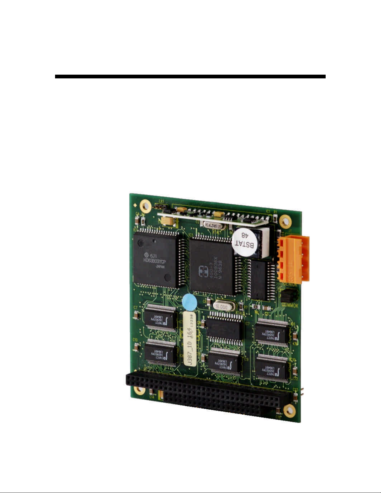
SMART TRAC Genius PCIM Card
Contents
Important Safety and Warranty Information 1
Warnings, Cautions and Notes.....................................................................................................................1
General Safety Precautions - Warnings ......................................................................................................2
Important Warranty Information................................................................................................................2
Smart Trac Genius PCIM Card 3
Capabilities.....................................................................................................................................................3
Specifications .................................................................................................................................................3
Quick Start.....................................................................................................................................................3
Genius Basics 5
Introduction...................................................................................................................................................5
Genius Network Topology ............................................................................................................................6
Cabling ...........................................................................................................................................................6
Network Length and Cabling.......................................................................................................................6
Terminating Resistor Specifications............................................................................................................6
Installing the Smart Trac Genius PCIM Card 7
Unpacking ......................................................................................................................................................7
Electrostatic Discharge (ESD) Procedures........................................................................................7
Unpacking Procedure........................................................................................................................7
Installing the Smart Trac Genius Card.......................................................................................................7
Connecting the Smart Trac Genius Card to a Genius Network..............................................................10
Configuring the Smart Trac Genius Card 11
Configuration...............................................................................................................................................11
Default Settings............................................................................................................................................11
Interrupt...........................................................................................................................................12
Non-Default Settings for Switch SW1........................................................................................................14
Serial Bus Address..........................................................................................................................14
Serial Bus Baud Rate ......................................................................................................................14
Outputs............................................................................................................................................15
Non-Default Settings for Switch SW2........................................................................................................15
Memory Location............................................................................................................................15
I/O Base (Port) Address ..................................................................................................................15
Watchdog Timer..............................................................................................................................16
Testing Card Installation 17
Testing the Network....................................................................................................................................17
On-board Indicator Lights .........................................................................................................................17
Technical Manual 3554-0080 Contents •• i
Page 4

SMART TRAC Genius PCIM Card
Troubleshooting Your Smart Trac Genius PCIM Card 19
General Troubleshooting Procedures........................................................................................................19
Checking Cabling............................................................................................................................19
Fault Isolation .................................................................................................................................19
Troubleshooting Table................................................................................................................................19
Appendix A - Technical Support 21
Getting Help.................................................................................................................................................21
References ....................................................................................................................................................21
Problem Report ...........................................................................................................................................22
Appendix B – Replaceable Parts Listing 23
Replaceable Parts Listing ...........................................................................................................................23
Appendix C – Removing the Smart Trac Card Stack 25
General Procedures.....................................................................................................................................25
Glossary of Terms 29
Index 31
ii •• Contents Technical Manual 3554-0080
Page 5
SMART TRAC Genius PCIM Card
Important Safety and Warranty
Information
Warnings, Cautions and Notes
WARNING
A statement of conditions which MUST BE OBSERVED to
prevent personal injury or death.
WARNING - ESD
A statement of conditions which must be observed to prevent
damage to components due to ESD (ElectroStatic Discharge) and
to prevent personal injury or death.
CAUTION
A statement of conditions which must be observed to prevent
undesired equipment faults, Smart Trac AC1 system degradation
and damage to equipment.
IMPORTANT
A statement of conditions which should be observed during Smart Trac AC
setup or operation to ensure dependable service.
NOTE: Notes indicate information that is in addition to a discussion of the topic
in adjoining text. Alternatively, it may limit or restrict the paragraph(s) that
follow(s) to specific models or conditions.
TIP - Tips indicate information that should make a procedure easier or more
efficient.
Technical Manual 3554-0080 Important Safety and Warranty Information •• 1
Page 6
SMART TRAC Genius PCIM Card
General Safety Precautions Warnings
Important safety information follows. Please read and understand all
precautions listed below before proceeding with the specification, installation,
set-up or operation of your Smart Trac AC1. Failure to follow any of the
following precautions may result in personal injury or death, or damage to the
equipment.
WARNING - ESD
The Control Printed Circuit Board (PCB) employs CMOS
Integrated Circuits that are easily damaged by static electricity.
Use proper ElectroStatic Discharge (ESD) procedures when
handling the Control PCB. See Smart Trac AC1 Technical Manual
for details. Failure to comply may result in damage to equipment
and/or personal injury.
Important Warranty Information.
Do not modify your Smart Trac AC1, its components, or any of the procedures
contained in the technical documentation supplied by MagneTek. Any
modification of this product by the user is not the responsibility of MagneTek
and will void the warranty.
2 •• Important Safety and Warranty Information Technical Manual 3554-0080
Page 7

SMART TRAC Genius PCIM Card
Smart Trac Genius PCIM Card
Capabilities
The Genius Card Option consists of a Smart Trac Genius PCIM card with
mounting hardware. The card supports Genius network communications using
the GE Fanuc Genius LAN Communications Protocol # 91.
Specifications
• Genius serial bus compatible connector
• Configurable for interrupts 5, 7, 11 and 12
• Supports baud rates of 153.6 Standard, 153.6 Enhanced, 76.8K and
38.4K
• Operating temperature
• Storage temperature
• Humidity 5% to 95% non-condensing
• Status LEDs indicate card health and network activity
Quick Start
1. Check DIP switch settings on the card against the default settings (see
"Default Settings"). You should accept the default settings in all but
unusual situations. Your Smart Trac Field Service Engineer can help
you if you need assistance.
2. Power OFF your Smart Trac AC1 and tag "Out of Service."
3. Install the card in your Smart Trac AC1 in a PC/104 Option card
position (above the Ethernet Card or another PC/104 Option card).
4. Connect the Genius network cable.
5. Test your card installation.
Technical Manual 3554-0080 Smart Trac Genius PCIM Card •• 3
Page 8

SMART TRAC Genius PCIM Card
THIS PAGE INTENTIONALLY LEFT BLANK
4 •• Smart Trac Genius PCIM Card Technical Manual 3554-0080
Page 9

Genius Basics
Introduction
Developed by General Electric, the Genius network provides an industrial
networking scheme with software-configurable fault reporting, input filter time,
overload detection, and I/O mix. Programmable inputs and outputs, part of
Genius I/O Blocks, allow any circuit to be set up for either input or output. This
means that one 8-circuit block is field-configurable to any of 256 distinct
combinations of inputs and outputs.
SMART TRAC Genius PCIM Card
A Genius network passes a token in what are called bus scans. The pass starts at
the controller, which passes the token to the first node. It is next passed on
through consecutively numbered nodes. When it gets the token, a node can send
messages. When done sending, it notifies the network that it is done and passes
the token to the node with the next highest address. Finally, the token is passed
to either node 15 or 31 (the baud rate and cable type determine the maximum
number of nodes). The process repeats.
NOTE: Node 31 is generally reserved for a CPU. Nodes 29 and 30 are generally
reserved for fault tolerant devices.
In each bus scan, inputs are broadcast to all CPUs on the bus. The CPUs send
outputs to specific nodes, as required. Typically, node 31 is the CPU
Information may also be sent using Datagrams. Each datagram includes sourceto-destination routing information. During each bus scan, one datagram may be
automatically sent from one node to another, specific node. It may also be sent
from the PLC or computer to I/O blocks. Each datagram may contain up to 128
bytes of data.
Nodes in a Genius network may automatically broadcast up to 128 bytes of
global data with each bus scan. All CPUs on the bus receive all broadcasts of
global data. The receiving nodes do not acknowledge receipt of global data.
Upon receipt of data, the receiving node performs a cyclic redundancy check
(CRC) to ensure data integrity.
Two or more buses may be used, for example, to split activity to I/O information
on one bus and communications information on another.
Technical Manual 3554-0080 Genius Basics •• 5
Page 10

SMART TRAC Genius PCIM Card
Genius Network Topology
Configured in a bus topology, Genius networks require no special equipment to
amplify or regenerate the signal. Transfer of information occurs across cables
via RS-485 serial modems. You must terminate each end of the bus. A Genius
network will support up to 32 devices at 153.6 Kbaud standard, 153.6 Kbaud
extended, or 76.8 Kbaud and up to 16 devices at 38.4 Kbaud.
You may arrange devices on a Genius network in any physical sequence on the
bus. For efficient communications, however, arrange devices in the same
sequence as their Node (Block) Numbers.
Cabling
Cabling a Genius network consists of single twisted pair shielded cable, daisychained bus cable or fiber optic cable. RS-485 serial modems transmit and
receive data node to node. With simple field wiring to and from a Terminal
Assembly, the cost of wiring and cabling a Genius network is relatively low.
Network Length and Cabling
The maximum bus length depends, in part, on baud rate. The maximums are:
• 7500 feet at 38.4 Kbaud.
• 4500 feet at 76.8 Kbaud.
• 3500 feet at 153.6 Kbaud extended.
• 2000 feet at 153.6 Kbaud, standard.
The maximum length at each baud rate also depends on cable type. See
references in the Appendices for a complete list of cable types, showing
corresponding bus lengths and baud rates.
Greater bus lengths are possible using sections of fiber optics cable with modems.
Terminating Resistor Specifications
You must install 75, 100, 120, or 150 ohm, 1/4 watt resistors at both ends of the
electrical bus cable. Resistors must have a tolerance of -10% to +20%
6 •• Genius Basics Technical Manual 3554-0080
Page 11
SMART TRAC Genius PCIM Card
Installing the Smart Trac Genius
PCIM Card
Unpacking
Electrostatic
Discharge (ESD)
Procedures
Unpacking Procedure
WARNING WARNING -- ESD ESD
Keep electronic circuit boards in Electrostatic Discharge (ESD) protective
bags when not being handled. Use proper ESD procedures (including an
ESD wrist strap) when handling circuit boards. Failure to comply may
result in damage to equipment
When working with an electrostatic discharge (ESD) sensitive device, you
should be grounded at all times. The easiest and most common way to provide
this ground is to use an approved ESD wrist strap. The strap is secured to your
wrist with a wire attached to the strap and clipped or taped to the chassis of the
unit being worked on. Any static is dissipated through the wire to ground,
greatly reducing the possibility of damage to the device.
It is a good idea to touch the chassis with your finger before handling any
electrostatic sensitive device. Any static electricity will be discharged to chassis
ground and will not be transferred to the device.
Always store devices (cards, other electronic components) in ESD protective
bags when not being handled.
Remove the protective shipping and packing material from the card. Ensure
contact wedges and other shipping devices have been removed.
Installing the Smart Trac Genius Card
The Smart Trac Genius Card is PC/104 compatible, so it may be positioned in
one of the PC/104 Option Card positions at the top of the Smart Trac card stack.
NOTE: If replacing or adding a Smart Trac Genius PCIM card to an existing
Smart Trac card stack, see "Appendix C – Removing the Smart Trac Card
Stack" before continuing.
Technical Manual 3554-0080 Installing the Smart Trac Genius PCIM Card •• 7
Page 12

Card
Genius PCIM
Smart Trac
SMART TRAC Genius PCIM Card
Standoffs (4
places on top of
each card)
4CN
Connector
Optional
PC/104
Card
Smart Trac
Ethernet
Card
Smart Trac
PS Card
Smart Trac
PG Card
2CN
Connector
Smart Trac
CPU Card
Inverter Control
Card
Adapter
Ring
Main Chassis
Figure 1. Smart Trac Genius PCIM Card Stack Position
WARNINGWARNING
Turn off and disconnect the main power to the Smart Trac AC1 before
opening the door and removing the PC/104 card from the unit. This avoids
a risk of electric shock. Failure to comply may result in personal injury or
death.
8 •• Installing the Smart Trac Genius PCIM Card Technical Manual 3554-0080
Page 13

SMART TRAC Genius PCIM Card
WARNING WARNING -- ESD ESD
To avoid damage from electrostatic discharge, adhere to the following
precautions when performing this procedure:
• The card is packaged in a static-safe bag which protects the
product during shipping. Before removing the card from this bag,
be prepared to handle it in a static-safe environment.
• Wear a properly functioning antistatic strap and be sure that you
are fully grounded. Never touch the card unless you are wearing
an antistatic strap.
• Any surface upon which you place the unprotected Genius card
should be static-safe, facilitated by antistatic mats, if possible.
• Extra caution should be taken in cold, dry weather, when static
charges can easily build up.
NOTE: It is not necessary to remove any card from the stack to install the Smart
Trac Genius PCIM card. The card can be placed on the very top of the card
stack.
1. Remove the Smart Trac Genius card from its static guard package.
2. Before installing the Smart Trac Genius card, make the proper Jumper
(Link) and Switch settings. A serial bus address of 28 (1Ch) is set as
the default. This can be changed according to your network
requirements.
NOTE: a switch setting of 0 is a logical 1. The Outputs, I/O Port Address, and
Watchdog Timer settings are default and should not be changed.
3. Make sure that a terminating resistor is installed at both ends of the
Genius network.
4. Install the four metal standoffs on the Smart Trac stack.
NOTE: Four metal standoffs are shipped with the Smart Trac Genius card.
These four standoffs are longer than those originally shipped with your Smart
Trac AC1. To provide adequate clearance for components on the Smart Trac
Genius card and those on the card below, use the standoffs provided with the
Smart Trac Genius card to attach the Genius card to the card below it in the card
stack.
5. Orient the Smart Trac Genius card so that the connector pins are
aligned with the PC/104 connector on the board below, and press it
carefully into place until it comes to rest on the four metal standoffs.
6. Secure the Smart Trac Genius card by installing the four 16mm M/F
brass standoffs included in the Smart Trac Genius accessory package
Tighten them down to secure, but DO NOT over tighten.
7. Connect the network cable.
8. Replace the option cards by reversing the above instructions. See
"Smart Trac AC1 Technical Manual" for details.
Technical Manual 3554-0080 Installing the Smart Trac Genius PCIM Card •• 9
Page 14

SMART TRAC Genius PCIM Card
Connecting the Smart Trac Genius
Card to a Genius Network
The Smart Trac Genius card connects to the Genius serial bus via a cable
installed at its 4-terminal connector (see Figure 1). Terminals are labeled Serial
1, Serial 2, Shield In, and Shield Out.
You connect the Serial 1 and Serial 2 terminals of each Smart Trac Genius card
to the corresponding Serial 1 and Serial 2 terminals of the next device.
You connect the Shield In of each block to Shield Out of the preceding device.
You may leave the Shield In of first device and the Shield Out of the last device
disconnected.
When making bus connections, leave no more than two inches of exposed bare
wire. Insultate each drain wire with shrink tube to prevent the Shield In and
Shield Out wires from touching each other.
Installation must conform to Genius I/O product guidelines for the screening of
cables and components for the Genius serial bus. Cable construction must
conform to the pinout below :
Table 1. Pinout for Genius Network Cable.
Pin Connect to: Comments
1 Serial 1 of next block By doing this, each device connects to the
2 Serial 2 of next block By doing this, each device connects to the
3 Shield Out of previous block By doing this, Shield Out of one device
4 Shield In of next block Not required if Smart Trac Genius card is
Shield In of Prev Block Shield Out
Shield Out of Prev Block
X2
X1
Shield In
Serial 2
Serial 1
previous and next devices.
previous and next devices.
connects to Shield In of the next device.
last device on Genius block.
Figure 2. Genius Network Connector.
10 •• Installing the Smart Trac Genius PCIM Card Technical Manual 3554-0080
Page 15

SMART TRAC Genius PCIM Card
Configuring the Smart Trac
Genius Card
Configuration
You configure the Smart Trac Genius card for the Genius serial bus by either
accepting default values or changing them to suit your unique situation. The
values chosen at installation of the Smart Trac Genius card software driver must
match those set on the card.
Bus Termination (LNK1)
Two switches on the Smart Trac Genius card allow user configuration of the
serial bus, memory locations, I/O Base Address, and enabling or disabling of
outputs.
Default Settings
The Smart Trac Genius card is shipped from the factory already configured for
the typical installation. Default Switch settings for SW1 and SW2 are described
below. Generally, you should accept these defaults and ensure the switches are
set correctly before installing your card.
A terminating resistor must be installed across Serial 1 and Serial 2 at both ends
of a Genius serial bus. Depending on the type of cable you use, you will need to
terminate with 75 ohm, 100 ohm, 120 ohm or 150 ohm resistors. When you're
connecting one end of the card to a 150 ohm serial bus, you use the 150 ohm
terminating resistor located onboard the Smart Trac Genius card.
Figure 3. Genius Card Jumpers.
Technical Manual 3554-0080 Configuring the Smart Trac Genius Card •• 11
Page 16

SMART TRAC Genius PCIM Card
Interrupt
Five jumpers on the Smart Trac Genius card, labeled LNK 1 through LNK 5,
determine the interrupt (IRQ) level. Make sure the IRQ of the Genius card does
not conflict with any of the other cards in the Smart Trac card stack.
NOTE: For the Genius card, use of IRQ 11 is highly recommended. IRQ may
be used if IRQ 11 cannot be used. IRQ 5 is the default Ethernet card setting.
IRQ 7 is the default DeviceNet card setting. The card supports IRQ 5, 7, 11 and
12.
To set the IRQ for the Genius card, install a jumper in one of four positions
(LNK2, LNK3, LNK4 or LNK 5).
Table 2. Smart Trac Genius card Jumper Settings.
Jumper Jumper or
IRQ
A LNK 1 Jumper on 150 ohm terminaltion on board.
No jumper Add 120, 100, or 75-ohm termination.
B LNK 2 IRQ 11 Default (Highly recommended)
LNK 3 IRQ 12 Recommended
LNK 4 IRQ 7 (default for Smart Trac DeviceNet card)
Termination Requirements
Switch SW1 (Serial Bus
Address, Baud Rate
and Outputs)
LNK 5 IRQ 5 (default for Smart Trac Ethernet card)
Switch SW1 allows setting the Smart Trac Genius card to match the parameters
of the Genius serial bus. The Standard Serial Bus Baud Rate of 153.6 should be
accepted when connecting the card to a bus on which Phase A devices are used.
0 = OFF 1 = ON
SW1 Default Settings
1 2 3 4 5 6 7 8
Serial Bus Addressing
Address 1 Ch
(Default)
1 1 0 0 0 0 0 0
Serial Bus
Baud Rate
153.6 Standard
(4 bit skip time)
Outputs
Disabled
12 •• Configuring the Smart Trac Genius Card Technical Manual 3554-0080
Page 17

SMART TRAC Genius PCIM Card
Figure 4. Genius Card Switch Locations (back of PCIM Card)
Switch SW2 (Memory
Address, I/O Base
Address, Watchdog
Timer)
Switch SW2 positions 1-4 determine a 16 kilobyte Memory location used by the
Smart Trac Genius card.
Switch SW2 positions 5-7 determine the I/O Base Address for the application
software.
Switch SW2 position 8 determines whether the Watchog Timer is disabled
(default) or enabled.
0 = OFF 1 = ON
SW2 Default Settings
1 2 3 4 5 6 7 8
Serial Bus Addressing
Address CC00h
(Default)
0 1 1 0 0 0 1 1
I/O Port
Address
3E0h
(Default)
Watchdog
Timer
(Disabled)
Technical Manual 3554-0080 Configuring the Smart Trac Genius Card •• 13
Page 18

SMART TRAC Genius PCIM Card
Non-Default Settings for Switch SW1
Your particular situation may demands setting switches to different values than
the defaults.
Serial Bus Address
The Bus Address may be set from 00 to 1F hexadecimal (0 to 31 decimal) using
SW1, Positions 1-5.
Positions 1-5 = Node Address (Position 1 = LSB or 1's digit, Position 5 = MSB
or 16's digit)
0 = Off 1 = On
SW1 Optional Settings – Positions 1-5
Value Position Value Position
1 2 3 4 5 1 2 3 4 5
SBA=0 1 1 1 1 1 SBA=16 1 1 1 1 0
SBA=1 0 1 1 1 1 SBA=17 0 1 1 1 0
SBA=2 1 0 1 1 1 SBA=18 1 0 1 1 0
SBA=3 0 0 1 1 1 SBA=19 0 0 1 1 0
SBA=4 1 1 0 1 1 SBA=20 1 1 0 1 0
SBA=5 0 1 0 1 1 SBA=21 0 1 0 1 0
SBA=6 1 0 0 1 1 SBA=22 1 0 0 1 0
SBA=7 0 0 0 1 1 SBA=23 0 0 0 1 0
SBA=8 1 1 1 0 1 SBA=24 1 1 1 0 0
SBA=9 0 1 1 0 1 SBA=25 0 1 1 0 0
SBA=10 1 0 1 0 1 SBA=26 1 0 1 0 0
SBA=11 0 0 1 0 1 SBA=27 0 0 1 0 0
SBA=12 1 1 0 0 1 SBA=28 1 1 0 0 0
SBA=13 0 1 0 0 1 SBA=29 0 1 0 0 0
SBA=14 1 0 0 0 1 SBA=30 1 0 0 0 0
SBA=15 0 0 0 0 1 SBA=31 0 0 0 0 0
Serial Bus Baud Rate
The Smart Trac Genius card can be set to communicate at four different baud
rates: 153.6 Standard, 153.6K Extended, 38.4K and 76.8K. Use SW1, positions
6 and 7 to set the baud rate.
0 = Off 1 = On\
SW1 Optional Settings – Positions 6-7 (serial bus baud rate)
Baud Rate Position 6 Position 7
153.6K Std (default) 0 0
76.8K 1 0
38.4 0 1
153.6K Extended 1 1
14 •• Configuring the Smart Trac Genius Card Technical Manual 3554-0080
Page 19

SMART TRAC Genius PCIM Card
Outputs
Memory Location
The Smart Trac Genius card may be set to either enable or disable outputs.
SW1 Optional Settings – Position 8 (Outputs)
Outputs Position 8
Outputs Disabled (default) 0
Outputs Enabled 1
Non-Default Settings for Switch SW2
The Smart Trac Genius card uses two consecutive bytes of I/O space and 16
Kbytes of memory in the host system. I/O and memory locations must not
conflict with any other with other memory or device addresses in use. The Smart
Trac Genius card's switch SW2, positions 1-4, determine the starting address for
16 kbytes of memory that is used to store I/O data, for communications buffers,
and other information.
0 = Off 1 = On
SW2 Optional Settings – Positions 1-4 (Memory Location)
16Kb Data
and Comm.
I/O Starting
Address 1 2 3 4
I/O Base (Port)
Address
C800 1 1 1 1
CC00 0 1 0 0
E000 1 0 0 1
E400 0 0 0 1
The I/O registers occupy 2 bytes of space in the host system. The application
software on the host system exchanges data with the Smart Trac Genius card by
reading and writing to the assigned I/O addresses. The host's I/O Base, or
starting, address is set using positions 5, 6 and 7 of SW2.
0 = Off 1 = On
SW2 Non-Default Settings – Positions 5-7 (I/O Base Address)
4-bytes I/O
Memory
Address
360 1 1 1
364 0 1 1
368 1 0 1
36C 0 0 1
3E0 1 1 0
3E4 0 1 0
3E8 1 0 0
3EC 0 0 0
5 6 7
Technical Manual 3554-0080 Configuring the Smart Trac Genius Card •• 15
Page 20

SMART TRAC Genius PCIM Card
Watchdog Timer
The Watchdog Timer monitors the host systemn and resets the Smart Trac
Genius card if the host malfunctions. Unless supported by the host system, it
should remain disabled. When enabled, the Watchdog Timer requires that the
Smart Trac Genius card receive a pulse from the host every 7 milliseconds. If
not, it resets the card.
Outputs Disabled (default) 0
Outputs Enabled 1
SW2 Non-Default Settings – Position 8 (Outputs)
Outputs Position 8
16 •• Configuring the Smart Trac Genius Card Technical Manual 3554-0080
Page 21

SMART TRAC Genius PCIM Card
Testing Card Installation
Testing the Network
Once installed, check the on-board indicator lights. Normally, both LEDs should
be illuminated.
On-board Indicator Lights
Two LED indicator lights on the Smart Trac Genius PCIM card provide systemrelated information:
• GENI 104 Self-test/Health LED: When ON, indicates that power is
available to the card and the card self-test was successful. When OFF,
indicates a card failure, improper address assignment, or that the /RST
input line is low.
• Communications LED: When ON, indicates that power is available to
the card and the controller's communications hardware is functional
and can send data (receives the token) every serial bus scan. When
OFF, indicates that an error has been detected in the communications
hardware or while accessing the Genius serial bus.
LED 1 - GEN 104 OK
LED 2 - Communications
PC/104 Connector
Figure 5. Genius Card Connectors and LEDs
Technical Manual 3554-0080 Testing Card Installation •• 17
Page 22

SMART TRAC Genius PCIM Card
THIS PAGE INTENTIONALLY LEFT BLANK
18 •• Testing Card Installation Technical Manual 3554-0080
Page 23

SMART TRAC Genius PCIM Card
Troubleshooting Your Smart
Trac Genius PCIM Card
General Troubleshooting Procedures
Most problems with installation occur at startup of a new network. Initial checks
include ensuring use of proper cabling and the status of card LEDs. Next,
analyze a problem using the "Troubleshooting Table."
Checking Cabling
Fault Isolation
Check that all cables are connected to the proper terminals and are secure. Make
sure that the proper cable has been chosen and length restrictions are not
exceeded.
Check the condition of the status indicator LEDs (see "On-board Indicator
Lights"). Both LEDs should be ON. If either LED is not ON, check the
troubleshooting table that follows for diagnosis and corrective action.
Troubleshooting Table
The table below describes symptoms, probable causes and correction action for
various problems you may encounter with your Smart Trac PCIM card. For
more general Genius network troubleshooting information, see "References."
Several actions identified in the table require the use of a Handheld Monitor
(HHM). This refers to a type of monitor sold by GE Fanuc. The HHM can force
I/O on and off and perform wiring diagnostics with or without the CPU
connected.
Genius PCIM Card Troubleshooting
Symptom Probable Cause Corrective Action
PCIM card installed, Smart
Trac powered up, both card
LEDs not ON, /RST input
HIGH.
Card not seated properly or
not receiving power.
Ensure card is seated
properly in the correct
position in Smart Trac card
stack.
Ensure power supply to
card is working properly.
Technical Manual 3554-0080 Troubleshooting Your Smart Trac Genius PCIM Card •• 19
Page 24

SMART TRAC Genius PCIM Card
Genius PCIM Card Troubleshooting
Symptom Probable Cause Corrective Action
PCIM card installed, Smart
Trac powered up, GENI104
Self-test/Health LED OFF
and Communications
(COMMS) LED ON.
Hardware failure Replace card.
PCIM card installed, Smart
Trac powered up, GENI 104
Self-test/Health LED ON
and Communications
(COMMS) LED OFF.
Jumper LNK1 not set
Serial bus wiring
High voltage runs interfering
Broken cable. Inspect for broken cable
PCIM card installed, Smart
Trac powered up, both
LEDs flashing together.
Repeated bus errors.
Failure of card. Unplug bus communications
System shuts down with
parity errors
System shuts down with
parity errors and bus errors.
Can't make Genius PCIM
card operable, despite
repeated attempts.
Smart Trac AC1 will not
boot with Genius PCIM card
installed.
DIP switch SW1 or SW2 or
both not set properly.
Improper cable type or
lengths exceeded.
properly.
incomplete.
with operation.
Same serial bus number
(device number) configured
with same address.
Shielding improperly
installed and/or grounded.
Input duplicated on same
bus or overlapping card I/O
references.
Serial 1 and Serial 2
connections crossed.
Short between regulator
U33 on main card and
bottom of option card.
Check switch settings are
correct.
Check cable type and
lengths, replace or
reconfigure as required.
Change to proper LNK1
setting.
Ensure serial bus wiring
completed in a daisy chain
fashion.
Ensure cabling is not near
high voltage runs.
and replace as necessary.
Check device numbers and
change to unique
addresses.
Change to meet proper
shielding and grounding
specifications.
cable from Genius PCIM
card. Use HHM (handheld
monitor) to read
configuration and compare
device numbers and I/O
reference numbers. Ensure
they are as planned.
Replace card as necessary.
Eliminate duplicate input or
overlapping card I/O
references.
Eliminate crossing of Serial
1 and Serial 2.
Bend over the three (3)-pin
regulator U33, so its metal
tab does not contact the
option card.
20 •• Troubleshooting Your Smart Trac Genius PCIM Card Technical Manual 3554-0080
Page 25

SMART TRAC Genius PCIM Card
Appendix A - Technical Support
Getting Help
Should you need technical assistance with installation or troubleshooting of your
Smart Trac AC1, you can phone our Help Desk at either (800)-541-0939 or
(262)-782-0200. Alternatively, you may copy the Problem Report form, found
on the next page, and fax it to us at (262)-782-3418.
References
MagneTek Drives and
Systems
PC/104 Specification,
Version 2.1
Publication GEK-90486-1,
"I/O System and
Communications"
For more information about MagneTek drives
and systems, training programs and contacts,
visit:
http://www.magnetekdrives.com
PC/104 Consortium. An overview and the
specification may be obtained at the web site
address:
http://www.controlled.com/pc104/index.html
GE Fanuc Technical Support. For more
information about Genius networks, design,
architecture and troubleshooting, visit:
http://www.gefanuc.com/infolink/manuals
Technical Manual 3554-0080 Appendix A - Technical Support •• 21
Page 26

SMART TRAC Genius PCIM Card
Problem Report
Name:
Address:
City: State: Zip
Serial Number: Smart Trac PG Card
Occurrence: Frequently Intermittantly Rarely
Nature of Problem:
Conditions when problem occurs:
22 •• Appendix A - Technical Support Technical Manual 3554-0080
Page 27

SMART TRAC Genius PCIM Card
Appendix B – Replaceable Parts
Listing
Replaceable Parts Listing
Description MagneTek Part
Number
Smart Trac PCIM (Genius) Network
Interface option kit
PCB, PCIM, Genius I/O, PC/104 05P00090-0556 1
Standoff, 4.5mm, Hex, Stl, CL
ZINC, 16mm, M/F, M3, M3
DOC, DWG, Assembly, Drive SZ 1-
20, B, PRO/E
Technical Manual – Smart Trac
Genius Card
Hardware Tools Kit for Smart Trac
AC1
Card Extraction Tool (Parvus
46S03643-0080 1
05P00618-0002 4
D-61S03554-0080 1
TM 3554-0080 1
TBD Option
Corporation) P/N
PRV-0760A-01
Qty
Option
Technical Manual 3554-0080 Appendix B – Replaceable Parts Listing •• 23
Page 28

SMART TRAC Genius PCIM Card
THIS PAGE INTENTIONALLY LEFT BLANK
24 •• Appendix B – Replaceable Parts Listing Technical Manual 3554-0080
Page 29

SMART TRAC Genius PCIM Card
Appendix C – Removing the
Smart Trac Card Stack
General Procedures
1. Power off the Smart Trac AC1. Disconnect it and tag "Out of Service".
2. Do one of the following:
• Open the cover to the Smart Trac AC1 by rotating the spring-
loaded, captive screw counterclockwise. Use a large screwdriver if
necessary to free the slotted screw.
OR
• Loosen the screws holding down the cover.
3. Disconnect the 12-pin wiring harness from connector J4 at the digital
operator.
4. Using the Phillips head screwdriver, remove the ground strap from the
left inside and the ground strap from the top inside of the Smart Trac
AC1 adapter ring.
5. Disconnect the 9-pin RS-232 cable at connector J5 on the Smart Trac
CPU card.
Technical Manual 3554-0080 Appendix C – Removing the Smart Trac Card Stack •• 25
Page 30

chassis
board
SMART TRAC Genius PCIM Card
12-pin wiring
harness on
Digital Operator
attached to
connector J4 on
Smart Trac
CPU Card
Digital
Operator
9-pin RS-232
cable
attached here
4mm screws
(4 places)
secure ring
to main
Standoffs (4
places)
secure each
board
Smart Trac
Board Stack
PC/104
9-pin RS-232
cable
connector J5
6. Using a 4.5mm hex head driver, remove four standoffs from the
topmost card.
7. Using the PC/104 extraction tool, remove the topmost card from the
stack.
Position
rectangular
"jacks"
around
edges of
PCBs
Squeeze to lift
cards apart
Figure 6. Using the PC/104 Extraction Tool.
8. Repeat step 8 above until all PC/104 cards have been removed.
9. To remove the Smart Trac PG card:
• Disconnect the 4CN connector on the PG card.
• Using a tubular extraction tool or pliers, squeeze the plastic,
spring-loaded retainer built-in to the long plastic standoff located
at the top of the PG card, just above connector J6.
• Using a PC/104 extraction tool, remove the card.
NOTE: The Smart Trac PG card requires unique handling. Wedge the extracting
tool between the PG card and the CPU card. The area between the terminal strip
on the CPU card and the serial numbered edge of the PG card can be lifted first,
then the opposite side (nearest TB1) on the PG card). Alternate sides until the
card is free of the CPU card.
10. To remove the Smart Trac CPU card:
26 •• Appendix C – Removing the Smart Trac Card Stack Technical Manual 3554-0080
Page 31

SMART TRAC Genius PCIM Card
• Disconnect the card at the 2CN connector on the CPU card.
• The CPU card is secured with three plastic standoffs with spring-
loaded clips on the end. Squeeze the top of the standoffs (the clips)
with the special cylindrical removal tool, your fingers or needlenosed pliers and lift the CPU card from the Smart Trac Inverter
Control Card.
You have removed the entire card stack. The inverter card, considered part of
the drive, is in clear view.
Technical Manual 3554-0080 Appendix C – Removing the Smart Trac Card Stack •• 27
Page 32

Page 33

Glossary of Terms
SMART TRAC Genius PCIM Card
Blocks
Datagram
fault tolerant
Topology
In a Genius networi, blocks are intelligent, self-contained, and configurable I/O
modules. Each block has its own communications capability and
microprocessors, and provides a number of circuits for connecting input and/or
output devices. Analog, discrete, and special-purpose blocks can be used on the
same bus.
A fixed length data packet including information to route it from source to
destination with no reliance on previous transmissions.
Resistant to software errors and hardware problems. A fault tolerant LAN keeps
running in the event of a power failure, a disk crash or other major events.
Redundant backbone cabling provides a degree of fault tolerance, so that if the
cable is cut, the network will continue to run.
The way in which devices on a network are physically connected: star, bus, or
mesh. The topology may define transmission media, adapters, and physical
design of the network.
Technical Manual 3554-0080 Glossary of Terms •• 29
Page 34

Page 35

Index
SMART TRAC Genius PCIM Card
C
cable 3, 5–6, 9, 13, 21–22
Capabilities 3
Configuration 13, 22
CPU 27
E
extraction tool 28
I
Inverter 29
L
LED 19, 21–22
R
registers 17
S
Specifications 3, 6, 22
Switch 3, 9, 13–17, 22
T
tool, extraction 28
troubleshooting 21, 23
Technical Manual 3554-0080 Index •• 31
Page 36

SMART TRAC Genius PCIM Card
Data subject to change without notice. Smart Trac is a trademark of MagneTek, Inc. MicroTrac is a registered trademark of MagneTek, Inc. Microsoft, Windows and Windows NT are registered
trademarks of Microsoft Corporation
MagneTek
Drives and Systems
16555 West Ryerson Road
New Berlin, WI 53151
(800) 541-0939, (262) 782-0200, FAX (262) 782-3418
TM 3554-0080 © 1999-2000 MagneTek, Inc. 01/31/2000
 Loading...