

Page 1

Technical Manual
™
™
S
M
A
R
S
M
A
R
T
T
T
T
F
F
R
R
a
a
A
C
A
C
ulltt
u
T
T
a
a
A
A
bll
b
C
1
C
1
ess
e
Page 2
10/17/00
Smart Trac
Faults.doc
Rev. # 19 Page 1 of 64
New Berlin
Technology Center
Product Development
Design
Document
Title: Fault Declarations
REV DATE NAME DESCRIPTION
0 04/23/98 J. Muszynski Original.
1 08/21/98 D. W. Karraker Split driver fault codes among known I/O drivers. Added sub-heading listing DPRAM faults.
2 12/04/98 D. W. Karraker Updated DPRAM and PCU faults
3 12/04/98 M. DuVal Added faults for PG-SC. Added cross reference column as to the actual error number shown in Smart Trac
Workstation SW
4 01/26/99 J. Cretney Added displayed fault codes to fault # 30016 through 30047
5 02/27/99 M. DuVal Added Smart Trac LAN fault table.
6 03/05/99 J. Cretney Merged C-Function Block Fault descriptions. Added decimal representation of fault codes.
7 03/22/99 M. DuVal Added more Smart Trac LAN fault codes.
8 03/23/99 T. Wiese Change LAN allocation errors from output to I/O
9 08/04/99 M. DuVal Added Operating System faults, Fault Range Map, and Document Revision. Removed unused sections. Reformatted
fault tables. Corrected documentation errors.
10 08/18/99 M. DuVal Include revisions from document design review. Added columns: Corrective Action and Assign Program Inputs.
11 09/10/99 T. Ellis Changed Assign Program Inputs to reflect correct values. Provided information for Corrective Actions. Document
clarification and corrections.
12 12/16/99 S. Mack Added new faults being declared by Function Blocks in MAG_WIND_V1_9 and MAG_STD_V1_9. Added to the
explanations of fault types.
13 12/20/99 D. W. Karraker Added individual CPF and OPE faults under Inverter Faults
14 01/05/00 M . DuVal Renamed references of MAG_CPB_V1_9 to MAG_STD_V1_9. Revised fault definitions in Function Blocks section
specific to MAG_STD_V1_9 library.
15 01/11/00 D. W. Karraker Added revision number for DPRAM driver to section 1.2
16 01/12/00 M. DuVal Minor changes to Function Blocks section.
17 01/31/00 D. W. Karraker Added inverter alarm codes
18 04/03/00 J. Nickel Added 2 fields to each fault code to indicate which list(s) the fault will be placed in by default: OLDEST or NEWEST.
Also added a column to indicate if the fault is considered a PRIORITY fault by default. Changed the description of
fault #77643 (CAVE Input). Changed legends of event codes 95736-95755 to include “Alm:”. Revised many of the
Corrective actions which were labeled ‘Consult Factory’. Added faults 12B08 – 12B0B, & 12B67. These are new
input faults for the DIAM_2, INRT_1, CTCW_0, CTCW_1 and POSR_0 blocks. Corrected some other typos in the
document. Added another Program Input called ‘FB_Setup’ for use to designate improper inputs to various block
inputs.
19 05/09/00 S. Mack DIAM_0 can declare NO_SYSTEM_CLOCK fault. DIAM_2 will declare DIAM_2_INPUT faults if sanity checks are
exceeded for NumberCalculation, RatedLineSpeed, S_RPM_at_M_RPM, MinDiameter, and MaxDiameter. Updated
Fault Document Revisions.
The informatio n co ntained in this docum e nt is the CONFIDENTIAL property of MagneTek Inc.
File = N:\PROJECT\515\SmartTrac\DOCS\Faults.DOC Print Date: 10/17/00
1
Page 3
10/17/00
Smart Trac
Faults.doc
Product Development
New Berlin
Technology Center
Design
Document
Title: Fault Declarations
REV DATE NAME DESCRIPTION
20 9/28/00 S. Mack Added PG_TACH Input fault. Fixed fault 11019 from REFQ to CTCW_1 Input fault.
Rev. # 19 Page 2 of 64
The informatio n co ntained in this docum e nt is the CONFIDENTIAL property of MagneTek Inc.
File = N:\PROJECT\515\SmartTrac\DOCS\Faults.DOC Print Date: 10/17/00
2
Page 4

10/17/00
Smart Trac
Faults.doc
Product Development
New Berlin
Technology Center
Design
Document
Title: Fault Declarations
Table of Contents
1. FAULT NUMBER ASSIGNMENTS 4
1.1 Fault Range Map 6
1.2 Fault Document Revision 7
2. OPERATING SYSTEM 8
3. USER DEFINED FAULTS 20
4. FUNCTION BLOCKS 21
5. DRIVERS 30
Rev. # 19 Page 3 of 64
5.1 DPRAM Driver 30
5.2 STLAN Driver 33
5.3 Operator Driver 37
6. INVERTER 38
7. IO SUBSYSTEM 59
8. BOOT 64
The informatio n co ntained in this docum e nt is the CONFIDENTIAL property of MagneTek Inc.
File = N:\PROJECT\515\SmartTrac\DOCS\Faults.DOC Print Date: 10/17/00
3
Page 5

10/17/00
Smart Trac
Faults.doc
Rev. # 19 Page 4 of 64
New Berlin
Technology Center
Product Development
Design
Document
Title: Fault Declarations
1. Fault Number Assignments
Xycom Automation has allowed MagneTek to use any “internal” fault number, in the range of 0 to 65535, to identify declared faults. (Internal faults are elaborated on below.)
This document is meant to assign ranges of numbers to the different aspects of the project, which may need to declare faults. There are a vast number of faults and this should
eliminate need for having duplicate fault numbers.
Faults number ranges will be assigned to the following broad categories:
1. Operating System
2. User Defined Faults
3. Function Bloc ks
4. Communications
5. Drivers
6. Inverter (PCU)
7. Hardware
8. IO Subsystem
9. Boot
10. Future
It shall be the responsibility of software engineers controlling each category to:
1. Further sub-divide the range as they deem appropriate.
2. Keep a common header or include file, under file control, with assigned fault numbers.
3. Keep a Word Document , under file control, defining the fault.
Faults have cl assification levels cal led Severity. Severity is the level at which a fault should be interpreted by the operating system. When a fault condition is detected, the
software that declares the fault also reports its severity. Four types of faults can occur: major faults, minor faults, function block setup faults and critical faults.
Major faults can halt execution of the task or node. Most major faults can be manually cleared and the task and node restarted. Major faults stop execution until they are cleared
by a task’s program or by the operator. If a major fault is encountered, the fault routine is run and the first thing that the fault routine should do is call G_FLT (i.e. Get Fault
function block) to get the current fault code. Depending on the fault code, it should deter mine if the s ystem should be shut down or clear the fault and restart execution. Call
C_FLT to clear the fault. Fault clearing can also be done externally by pressing RESET on the Digital Operator. (Typically, automatic clearing of major faults is not
recommended. Fault clearing should be initiated by the machine operator.) Major faults cleared by the Control Node Monitor will cause execution to begin from the start of the
program. If the Major fault is cleared after executing the fault routine, execution of the function block will restart at the point at which the fault was declared. This very important
to understand. For example in a structured text program, if a fault is declared on a certain line, then it is restarted on the following line.
The informatio n co ntained in this docum e nt is the CONFIDENTIAL property of MagneTek Inc.
File = N:\PROJECT\515\SmartTrac\DOCS\Faults.DOC Print Date: 10/17/00
4
Page 6

10/17/00
Smart Trac
Faults.doc
Rev. # 19 Page 5 of 64
New Berlin
Technology Center
Product Development
Design
Document
Title: Fault Declarations
Minor faults are logged, but do not halt the system. Minor faults can be cleared. Minor faults do not cause the task’s fault routine to run.
Function block setup faults (FB_SETUP) are those that indicate at least one input of a function block has been supplied with an illegal input.
Critical faults behave similar to major faults in the fact that execution is halted when a critical fault is encountered. The exception is, a critical fault cannot be cleared nor will the
node be allowed to run until node power has been recycled.
The Application Engineer may determine the type of fault (i.e., Major or Minor) only for the User Defined faults. In the other category of faults, the types are predefined and
cannot be changed by the Application Engineer .
1
Faults can be assigned to certain inputs such that the program can react when a fault occurs. These inputs are categorized in this document as Assign Program Input
The Fault Manager I/O Driver has a variable number of logic inputs (BOOLs). Each of these logic inputs will be set true if any of the faults pre-assigned to that logic input is
declared. It will remain true until all faults assigned to that input have been reset. Any number of faults may be assi gned to any of the inputs. The Fault Manager Interface Card is
the mechanism for defining the number of logic inputs, their symbols, and the list of fault codes assigned to that input. The default symbols used in the faults definition document
are “Critical”, “Major”, and “Minor”. These symbol names and the faults assigned to them may be changed by the Application Engineer.
Faults can be displayed in up to three places in a Smart Trac AC1 system: twice in Smart Trac AC1 Workstation and once on the Digital Operator. Specifically, the workstation
shows fault numbers in two places, a) Fault Manager Interface Card, and b) Control Node Monitor. Unfortunately, the same fault has a different number, depending on whether it
is displayed in the Fault Manager or Control Node Monitor. Fault Manager sho ws the fault in decimal while Control Node Monitor shows the number in hexadecimal. This is a
“feature” that was given to us by Xycom Automation. The Digital Operator does not display a fault number rather a Fault Legend. All tables in the ensuing sections have cross
references for each fault.
.
Although fault numbers are displayed in Fault Manager and Control Monitor, a third column has been added to many of the tables in this document: Internal Fault No. An
internal fault number is the number MagneTek development engineers use to identify a fault within a given piece of software and is of no consequence to the Application
Engineer. The displayed fault is equal to the internal fault number + 65,536 (i.e. 10000 HEX). Internal fault numbers are not displayed.
1
Also known as ‘Define Outputs’ tab in Fault Manager Interface Card of Smart Trac AC1 Workstation software.
The informatio n co ntained in this docum e nt is the CONFIDENTIAL property of MagneTek Inc.
File = N:\PROJECT\515\SmartTrac\DOCS\Faults.DOC Print Date: 10/17/00
5
Page 7
10/17/00
Smart Trac
Faults.doc
Rev. # 19 Page 6 of 64
New Berlin
Technology Center
Product Development
Design
Document
Title: Fault Declarations
There are three columns following the description of each fault. These are labeled Priority Display, Newest List and Oldest List. Faults which are selected to be a Priority
Display will preempt the local operator from whatever it was doing with a display this fault when it happens. Those faults which are selected to be on the Newest List (and/or
Oldest List) will be placed in the ‘newest’ (or ‘oldest’) list maintained by the fault manager. The Newest List can be thought of as a circular buffer that always contains the
newest faults that have been recorded on this drive. Any fault designated as to be placed on the Newest List will cause the oldest entry on this circular buffer to be discarded if
the Newest List already filled to capacity. The Oldest List can best be thought of as a table with 20 slots. Any fault designated to be placed on the Oldest List will remain on
this list until it is cleared via the local operator. If the Oldest List already filled up, and a fault designated to be placed on the Oldest List occurs, it will NOT be placed o n the
Oldest List. This is done to preserve the fault history of the original event that may have caused many subsequent faults to occur.
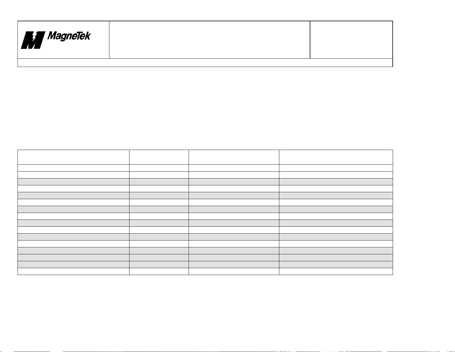
1.1 Fault Range Map
This table summarizes all possible fault value locations.
Fault Type
Operating System N/A 0 to FFFF 0 to 65,535
User Defined Faults 00000 to 09999 10000 to 1270F 65,536 to 75,535
Reserved for future u se #1 10000 to 10999 12710 to 12AF7 75,536 to 76,535
Function Block Faults 11000 to 11999 12AF8 to 12EDF 76,536 to 77,535
Reserved future Communications Protocols 12000 to 19999 12EE0 to 14E1F 77,536 to 85,535
Driver Faults: DPRAM 20000 to 20099 14E20 to 14E83 85,536 to 85,635
Reserved for future d riv e r #1 20100 to 20199 14E84 to 14EE7 85,636 to 85,735
Driver Faults: STLAN 20200 to 20299 14EE8 to 14F4B 85,736 to 85,835
Reserved for future d riv e r #2 20300 to 20399 14F4C to 14FAF 85,836 to 85,935
Driver Faults: OPERATOR 20400 to 20499 14FB0 to 15013 85,936 to 86,035
Reserved for future d riv e r #3 20500 to 29999 15014 to 1752F 86,036 to 95,535
Inverter Faults 30000 to 39999 17530 to 19C3F 95,536 to 105,535
Reserved for future u se #2 40000 to 59999 19C40 to 1EA5F 105,536 to 125,535
Reserved for future hardware platform fau lts 60000 to 65535 1 E A60 to 1FFFF 125,536 to 131,071
Not Used N/A 20000 to 8FFFFFFF 131,072 to 2,415,919,103
IO Subsystem N/A 90000000 to 90000043 N/A
Internal Fault Range
(Decimal)
Displayed in Control Node
Monitor (Hex)
Displayed in Fault Manager Interface Card
(Decimal)
The informatio n co ntained in this docum e nt is the CONFIDENTIAL property of MagneTek Inc.
File = N:\PROJECT\515\SmartTrac\DOCS\Faults.DOC Print Date: 10/17/00
6
Page 8
10/17/00
Smart Trac
Faults.doc
Rev. # 19 Page 7 of 64
New Berlin
Technology Center
Product Development
Design
Document
Title: Fault Declarations
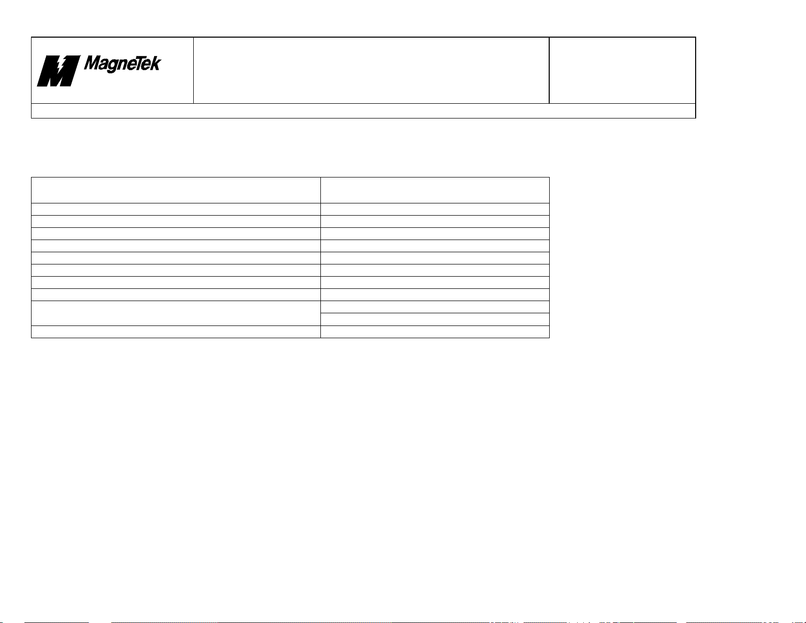
1.2 Fault Document Revision
This table lists the latest version of each fault type. As developers make enhancements that affect faults, they should update the corresponding section and change the
Software/Firmware (SW/FW) Version level accordingly. In this way, we can track whether this document has been properly updated.
SW/FW Type
ASIC-300 Workstation 4.2.4
Operating System and IO Subsystem (i.e., Kernel and Monitor) 4.2.0
Library: MAG_STD_V1_9 1.9
Library: MAG_WIND_V1_10 1.10
Library: MAG_PG_V1_7 1.7
Driver: DPRAM 1.7
Driver: STLAN 2.4
Driver: OPERATOR 1.10
Smart Trac AC1 Inverter
Boot 1.2.0
SW/FW Version
G112131.DAT (R1) for G5+
G110200.DAT (R1) for G5 Parallel HP units
The informatio n co ntained in this docum e nt is the CONFIDENTIAL property of MagneTek Inc.
File = N:\PROJECT\515\SmartTrac\DOCS\Faults.DOC Print Date: 10/17/00
7
Page 9
10/17/00
Smart Trac
Faults.doc
Product Development
New Berlin
Technology Center
Design
Document
Title: Fault Declarations
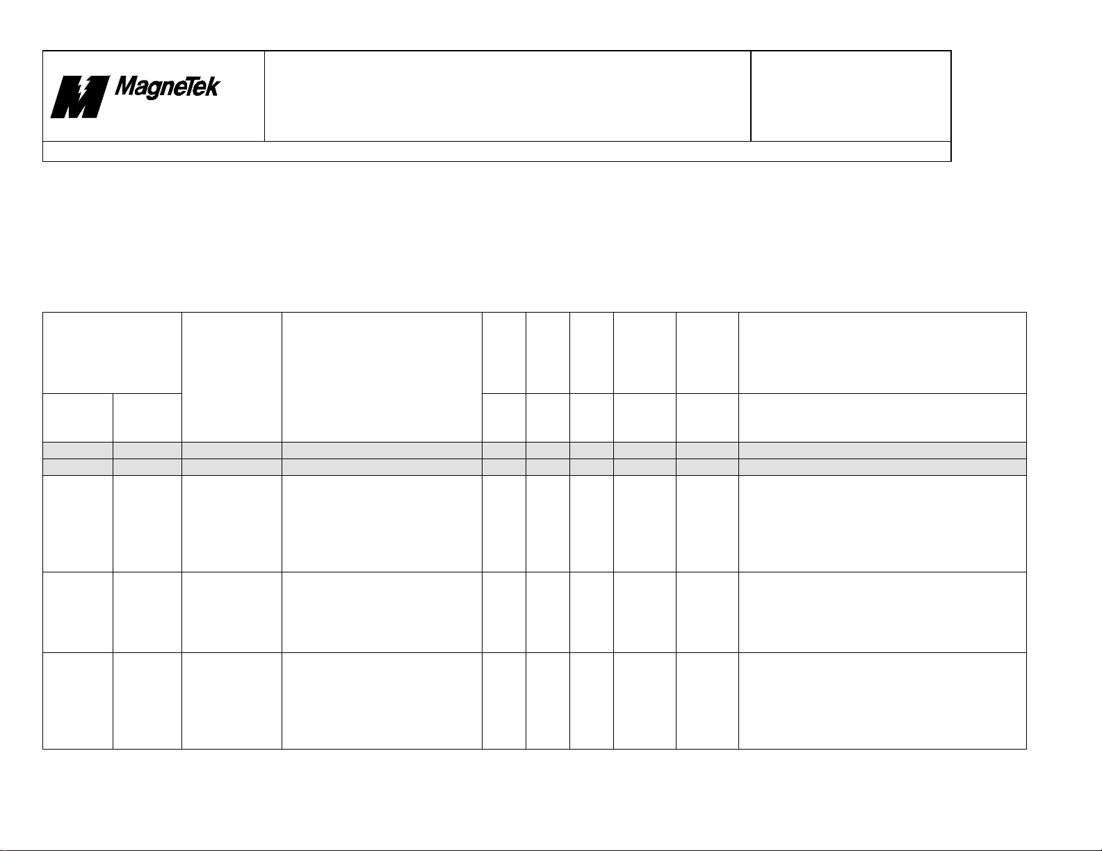
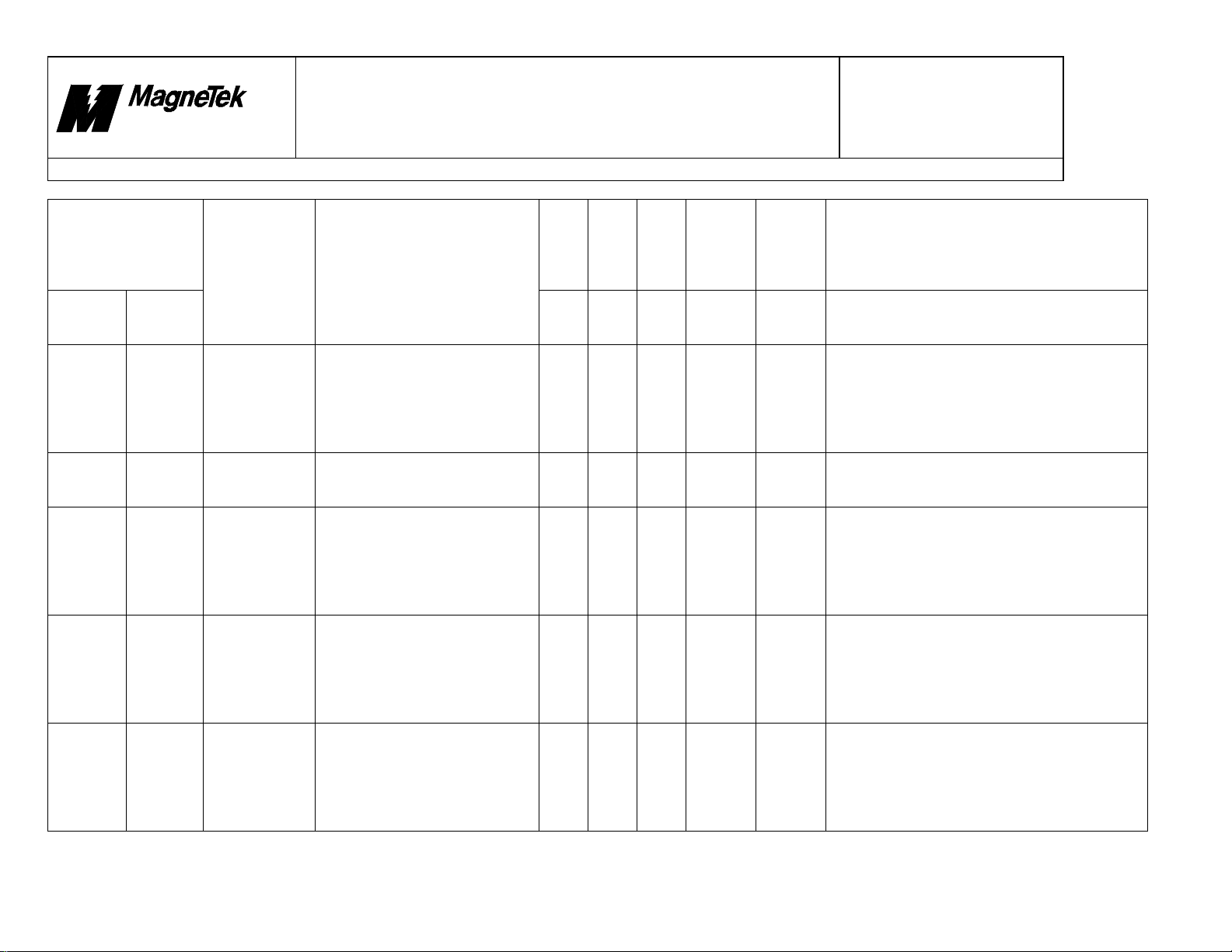
2. Operating System
The following section details fault numbers assigned to the Smart Trac AC1 Operating System.
Notes:
• Fault legend cannot be changed in this section.
• Internal fault values do not apply here. Operating System faults are not added with 10000 HEX.
• The Severity for every Operating System fault in this section is fixed in firmware. It cannot be changed
Display?
Priority
Newest
Displayed Fault No.
Fault Legend Description
Control
Node
Monitor
0 0 Not a fault
1 1 Not a fault
2 2 Invalid
3 3 Stack
4 4 Stack
The informatio n co ntained in this docum e nt is the CONFIDENTIAL property of MagneTek Inc.
File = N:\PROJECT\515\SmartTrac\DOCS\Faults.DOC Print Date: 10/17/00
Fault
Manager
Opcode
Overflow
Underflow
Operand code within program is
unrecognized. Valid Opcodes
are add, subtract, AND, OR, etc.
Program point er has gone past
the end of the program stack.
Stack is checked at the end of
each program scan.
Program pointer has preceded
the beginning of the program
stack. Stack is checked at the
end of each program scan.
8
List?
Yes Yes Yes Major
Yes Yes Yes Major
Yes Yes Yes Major
Oldest
List?
Severity
Program
Input
Major
Major
Major
Rev. # 19 Page 8 of 64
Assign
Corrective Action
Verify that there are no hardware problems on
the PC used to create the application. Recompile and reload the program and reload it to
the SmartTrac drive. The Smart Trac main CPU
card may be faulty. If available, download a
small test program to see if fault persists.
Application program may be overburdened –
reduce amount of logic placed in fast Tasks
(15ms or faster) to slow Tasks (30 ms or slower).
This may include reducing number of Program
Units and/or program elements.
Verify that there are no hardware problems on
the PC used to create the application. Recompile and reload the program and reload it to
the SmartTrac drive. The Smart Trac main CPU
card may be faulty. If available, download a
small test program to see if fault persists.
Page 10
10/17/00
Smart Trac
Faults.doc
New Berlin
Technology Center
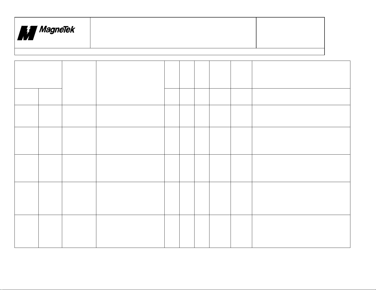
Title: Fault Declarations
Displayed Fault No.
Fault Legend Description
Control
Node
Monitor
5 5 Stack
66Call
7 7 Call Overflow Cannot process next Opcode
88Task
9 9 Operand
Fault
Manager
Corrupted
Underflow
Corrupted
Undrflow
Location of program stack has
inadvertently changed. Stack is
checked at the end of each
program scan.
Cannot process next Opcode
because a program pointer has
preceded the beginning of the
program stack.
because a program pointer has
gone past the end of the program
stack.
A stack that contains code for
each Task to be run is bad.
A computation is smaller than
the smallest quantity the CPU
can store.
Product Development
Design
Document
Display?
Priority
Newest
List?
Yes Yes Yes Major
Yes Yes Yes Major
Yes Yes Yes Major
Yes Yes Yes Major
No Yes Yes Minor
Rev. # 19 Page 9 of 64
Oldest
List?
Severity
Program
Input
Major
Major
Major
Major
Minor
Assign
Corrective Action
The Smart Trac main CPU card may be faulty. If
available, download a small test program to see
if fault persists.
Verify that there are no hardware problems on
the PC used to create the application. Recompile and reload the program and reload it to
the SmartTrac drive. Replace the SmartTrac
CPU card.
Verify that there are no hardware problems on
the PC used to create the application. Recompile and reload the program and reload it to
the SmartTrac drive. Replace the SmartTrac
CPU card.
Verify that there are no hardware problems on
the PC used to create the application. Recompile and reload the program and reload it to
the SmartTrac drive. The Smart Trac main CPU
card may be faulty. If available, download a
small test program to see if fault persists.
Verify that there are no hardware problems on
the PC used to create the application. Recompile and reload the program and reload it to
the SmartTrac drive. The Smart Trac main CPU
card may be faulty. If available, download a
small test program to see if fault persists.
The informatio n co ntained in this docum e nt is the CONFIDENTIAL property of MagneTek Inc.
File = N:\PROJECT\515\SmartTrac\DOCS\Faults.DOC Print Date: 10/17/00
9
Page 11
10/17/00
Smart Trac
Faults.doc
New Berlin
Technology Center
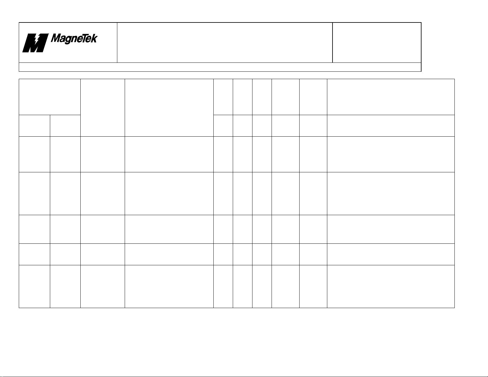
Title: Fault Declarations
Displayed Fault No.
Fault Legend Description
Control
Node
Monitor
A 10 Divide By
B11Result
C12Result
D 13 Invalid Result Fl oating point e rror: Compute d
E 14 Bad Address
Fault
Manager
Zero
Underflow
Overflow
Mode
An attempt was made to use ‘0’
as a divisor during computation.
Floating point error: 1) a
computation is smaller than the
smallest quantity the CPU can
store; 2) An error condition
occurred when an item was
called from an empty stack.
Floating point error: An error
occurred when calculated data
could not fit within the
designated field.
result is incorrect or is not within
bounds.
Operand address mode is not
recognized. Examples of correct
addressing is Direct and Indirect.
Product Development
Design
Document
Display?
Priority
Newest
List?
No Yes Yes Minor Software used to create the application program
No Yes Yes Minor
No Yes Yes Minor
No Yes Yes Minor
Yes Yes Yes Major
Rev. # 19 Page 10 of 64
Oldest
List?
Severity
Program
Input
Minor
Minor
Minor
Major
Assign
Corrective Action
may have been old. (Earlier Kernel and library
versions exhibited this problem.) Check the
application program for use of zero during
division.
Check the application program for use of
extremely large and/or small numbers for
computation.
Check the application program for use of
extremely large and/or small numbers for
computation.
Check the application program for use of
extremely large and/or small numbers for
computation.
Verify that there are no hardware problems on
the PC used to create the application. Recompile and reload the program and reload it to
the SmartTrac drive. The Smart Trac main CPU
card may be faulty. If available, download a
small test program to see if fault persists.
The informatio n co ntained in this docum e nt is the CONFIDENTIAL property of MagneTek Inc.
File = N:\PROJECT\515\SmartTrac\DOCS\Faults.DOC Print Date: 10/17/00
10
Page 12
10/17/00
Smart Trac
Faults.doc
New Berlin
Technology Center
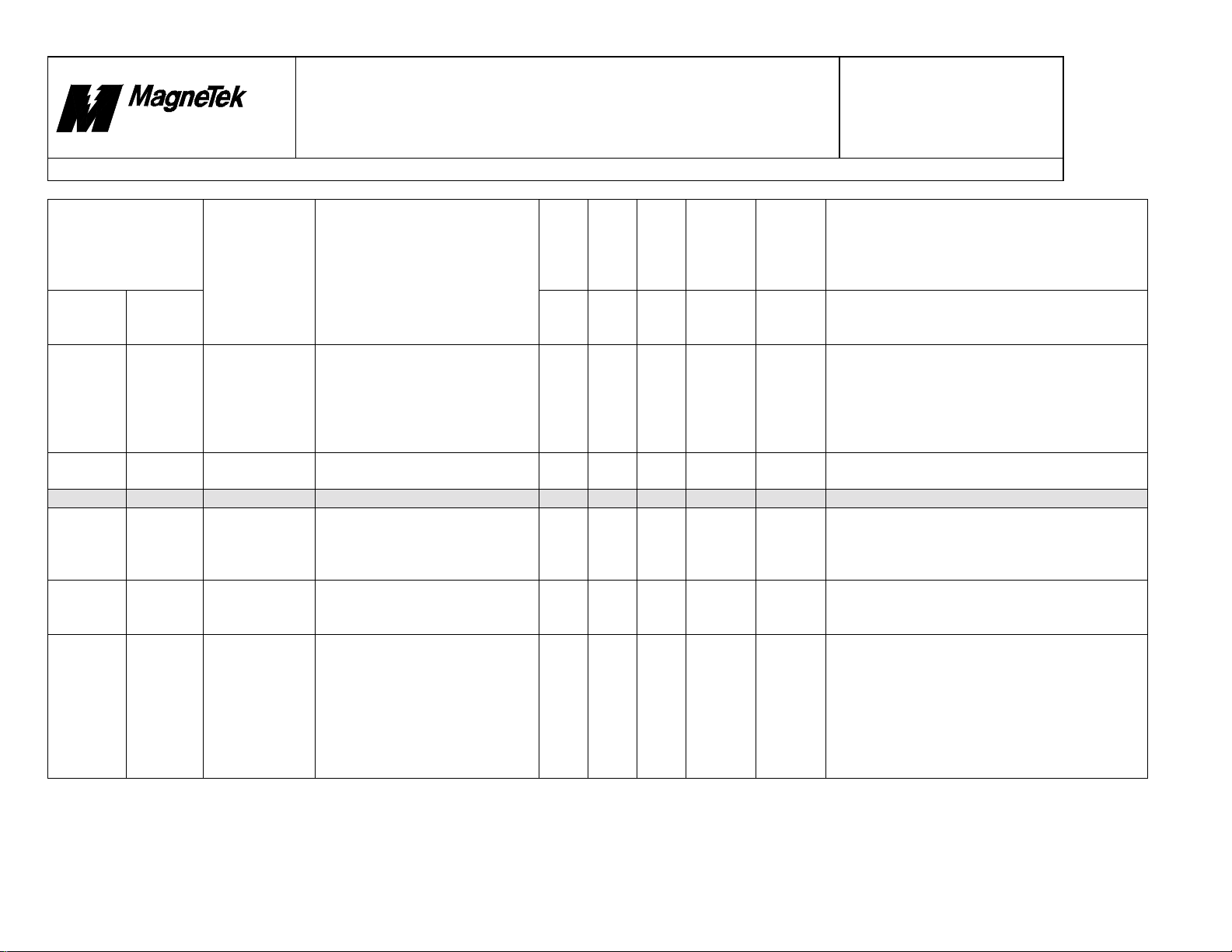
Title: Fault Declarations
Displayed Fault No.
Fault Legend Description
Control
Node
Monitor
F 15 Address
10 16 Data Unknown Operand type does not conform
11 17 Not used
12 18 Data
13 19 Bad Data Type Operand type cannot be used for
14 20 Bad Address An attempt has been made to
Fault
Manager
Mismatch
Mismatch
Address types are not equivalent.
This prohibits a valid
computation or comparison from
taking place.
to any available form.
Operand types are not
equivalent. This prohibits a valid
computation or comparison from
taking place.
this specific computation or
comparison.
access data from an invalid
memory location.
Product Development
Design
Document
Display?
Priority
Newest
List?
Yes Yes Yes Major
Yes Yes Yes Major
Yes Yes Yes Major
Yes Yes Yes Major
Yes Yes Yes Major
Rev. # 19 Page 11 of 64
Oldest
List?
Severity
Program
Input
Major
Major
Major
Major
Major
Assign
Corrective Action
Verify that there are no hardware problems on
the PC used to create the application. Recompile and reload the program and reload it to
the SmartTrac drive. The Smart Trac main CPU
card may be faulty. If available, download a
small test program to see if fault persists.
Valid types include byte, unsigned long,
Boolean, float, etc.
Check application program for improper data
type comparisons. Valid types include byte,
unsigned long, Boolean, float, etc.
Check application program for improper
comparisons. Example of this is attempting to
compare a Boolean with a string pointer.
Check memory allocation for this node in Smart
Trac AC1 Workstation software. In Configure
dialog box, make sure the following is true:
Base Address = 0x300000, Base Memory Size =
0x100000, Retentive Address = 0xDC000, and
Retentive Size = 0x3F00. The Smart Trac main
CPU card may be faulty. If available, download
a small test program to see if fault persists
The informatio n co ntained in this docum e nt is the CONFIDENTIAL property of MagneTek Inc.
File = N:\PROJECT\515\SmartTrac\DOCS\Faults.DOC Print Date: 10/17/00
11
Page 13

10/17/00
Smart Trac
Faults.doc
New Berlin
Technology Center
Title: Fault Declarations
Displayed Fault No.
Fault Legend Description
Control
Node
Monitor
15 21 Operand2
16 22 Operand1
17 23 Invalid Jump Calculated offset appears outside
18 24 Invalid
Fault
Manager
Invalid
Invalid
Address
2nd operand code within program
is unrecognized. Valid Opcodes
are add, subtract, AND, OR, etc.
1st operand code within program
is unrecognized. Valid Opcodes
are add, subtract, AND, OR, etc.
the bounds of the program.
Branch cannot be completed.
Address does not appear within
NVRAM, DRAM, nor Task
table.
Product Development
Design
Document
Display?
Priority
Newest
List?
Yes Yes Yes Major
Yes Yes Yes Major
Yes Yes Yes Major
Yes Yes Yes Major
Rev. # 19 Page 12 of 64
Oldest
List?
Severity
Program
Input
Major
Major
Major
Major
Assign
Corrective Action
Verify that there are no hardware problems on
the PC used to create the application. Recompile and reload the program and reload it to
the SmartTrac drive. Replace the SmartTrac
CPU card.
Verify that there are no hardware problems on
the PC used to create the application. Recompile and reload the program and reload it to
the SmartTrac drive. The Smart Trac main CPU
card may be faulty. If available, download a
small test program to see if fault persists.
Verify that there are no hardware problems on
the PC used to create the application. Recompile and reload the program and reload it to
the SmartTrac drive. The Smart Trac main CPU
card may be faulty. If available, download a
small test program to see if fault persists.
Check memory allocation for this node in Smart
Trac Workstation software. In Configure dialog
box, make sure the following is true: Base
Address = 0x300000, Base Memory Size =
0x100000, Retentive Address = 0xDC000, and
Retentive Size = 0x3F00. The Smart Trac main
CPU card may be faulty. If available, download
a small test program to see if fault persists
The informatio n co ntained in this docum e nt is the CONFIDENTIAL property of MagneTek Inc.
File = N:\PROJECT\515\SmartTrac\DOCS\Faults.DOC Print Date: 10/17/00
12
Page 14

10/17/00
Smart Trac
Faults.doc
New Berlin
Technology Center
Title: Fault Declarations
Displayed Fault No.
Fault Legend Description
Control
Node
Monitor
19 25 Float Error Floating point error: an unknown
1A 26 Fstack
1B 27 Fstack
1C 28 Bad Operand Based on the operand’s mode,
Fault
Manager
Overflow
Underflow
float error, which is detected
only if all other floating point
errors have not triggered a fault
(underflow, overflow, float
invalid).
Float stack overflow. Float
pointer has gone past the end of
the float stack.
Float stack underflow. Float
pointer has preceded the
beginning of the float stack.
operand address is invalid.
Product Development
Design
Document
Display?
Priority
Newest
List?
No Yes Yes Minor
Yes Yes Yes Minor
Yes Yes Yes Minor
Yes Yes Yes Major
Rev. # 19 Page 13 of 64
Oldest
List?
Severity
Program
Input
Minor
Major
Major
Major
Assign
Corrective Action
Verify that there are no hardware problems on
the PC used to create the application. Recompile and reload the program and reload it to
the SmartTrac drive. The Smart Trac main CPU
card may be faulty. If available, download a
small test program to see if fault persists.
Verify that there are no hardware problems on
the PC used to create the application. Recompile and reload the program and reload it to
the SmartTrac drive. The Smart Trac main CPU
card may be faulty. If available, download a
small test program to see if fault persists.
Verify that there are no hardware problems on
the PC used to create the application. Recompile and reload the program and reload it to
the SmartTrac drive. The Smart Trac main CPU
card may be faulty. If available, download a
small test program to see if fault persists.
Verify that there are no hardware problems on
the PC used to create the application. Recompile and reload the program and reload it to
the SmartTrac drive. The Smart Trac main CPU
card may be faulty. If available, download a
small test program to see if fault persists.
The informatio n co ntained in this docum e nt is the CONFIDENTIAL property of MagneTek Inc.
File = N:\PROJECT\515\SmartTrac\DOCS\Faults.DOC Print Date: 10/17/00
13
Page 15

10/17/00
Smart Trac
Faults.doc
New Berlin
Technology Center
Title: Fault Declarations
Displayed Fault No.
Fault Legend Description
Control
Node
Monitor
1D 29 Operand
1E 30 Out of
1F 31 Action Invalid Based on what is encountered in
20 32 I/O Read Fail Could not read input image table
21 33 I/O Write Fail Could not write to output image
Fault
Manager
Negative
Memory
Situation where a value should
not be negati ve. The SQRT,
LOG and LN functions will
declare this fault if their input is
negative.
Attempt to allocate memory for
the program stack and initialize
it to zero has failed.
the program, certain routines or
‘actions’ are processed. If the
requested action does not match
those that are available, this fault
will be realized.
for an associated driver, i.e.,
Interface Card.
table for an associated driver,
i.e., Interface Card.
Product Development
Design
Document
Display?
Priority
Newest
List?
No Yes Yes Minor
Yes Yes Yes Major
Yes Yes Yes Major
Yes Yes Yes Major
Yes Yes Yes Major
Rev. # 19 Page 14 of 64
Oldest
List?
Severity
Program
Input
Minor
Major
Major
Major
Major
Assign
Corrective Action
Search your application program to ensure that
only positive values can be input to the SQRT,
LOG and/or LN functions.
The Smart Trac main CPU card may be faulty. If
available, download a small test program to see
if fault persists.
Verify that there are no hardware problems on
the PC used to create the application. Recompile and reload the program and reload it to
the SmartTrac drive. The Smart Trac main CPU
card may be faulty. If available, download a
small test program to see if fault persists.
An Interface Card (driver) may be out of date.
Check for valid installed hardware. For example,
if using the STLAN driver, make sure an
ARCNET card is part of the Smart Trac drive
card stack.
An Interface Card (driver) may be out of date.
Check for valid installed hardware. For example,
if using the STLAN driver, make sure an
ARCNET card is part of the Smart Trac drive
card stack. The Smart Trac main CPU card may
be faulty. If available, download a small test
program to see if fault persists
The informatio n co ntained in this docum e nt is the CONFIDENTIAL property of MagneTek Inc.
File = N:\PROJECT\515\SmartTrac\DOCS\Faults.DOC Print Date: 10/17/00
14
Page 16

10/17/00
Smart Trac
Faults.doc
New Berlin
Technology Center
Title: Fault Declarations
Displayed Fault No.
Fault Legend Description
Control
Node
Monitor
22 34 Bad C Call A functional call within the
23 35 String Overrun Length of text to be displayed
24 36 Negative Shift During conversion of a data type
25 37 Bad Coercion Invalid data type promotion, i.e.,
26 38 Bad Address
Fault
Manager
Mode
program failed. Specifically, the
amount of information being
placed on stack(s) will exceed
limit.
exceeds maximum number of
allowable characters.
(number), the argument used to
specify how many places to shift
was negative .
change a ‘double’ to a ‘byte’.
Problem found when validating
operand types. Incorrect mode
used when processing oper and
and data type.
Product Development
Design
Document
Display?
Priority
Newest
List?
Yes Yes Yes Major
No Yes Yes Minor
No Yes Yes Minor
Yes Yes Yes Major
No Yes Yes Minor
Rev. # 19 Page 15 of 64
Oldest
List?
Severity
Program
Input
Major
Minor
Minor
Major
Minor
Assign
Corrective Action
Application program may be overburdened –
reduce amount of logic placed in fast Tasks
(15ms or faster) to slow Tasks (30 ms or slower).
This may include reducing number of Program
Units and/or program elements.
Avoid use of extremely long text. Function
Block names and symbol names should be kept
to a manageable length (< 64 chars).
Verify that there are no hardware problems on
the PC used to create the application. Recompile and reload the program and reload it to
the SmartTrac drive. The Smart Trac main CPU
card may be faulty. If available, download a
small test program to see if fault persists.
Check application program for data type
mismatches.
Verify that there are no hardware problems on
the PC used to create the application. Recompile and reload the program and reload it to
the SmartTrac drive. The Smart Trac main CPU
card may be faulty. If available, download a
small test program to see if fault persists.
The informatio n co ntained in this docum e nt is the CONFIDENTIAL property of MagneTek Inc.
File = N:\PROJECT\515\SmartTrac\DOCS\Faults.DOC Print Date: 10/17/00
15
Page 17
10/17/00
Smart Trac
Faults.doc
New Berlin
Technology Center
Title: Fault Declarations
Displayed Fault No.
Fault Legend Description
Control
Node
Monitor
27 39 Bad Bit
28 40 Bad Data Size Mismatch found when
29 41 Bit Out of
2A 42 Bad Function
2B 43 Bad Lower
Fault
Manager
Number
Range
Ptr
Bound
Requested bit number is
unavailable.
performing computation on 2
differing data types.
Logical bit does not fit within
bounds of data type. For
example, an attempted was made
to OR bit 0x0800 with a byte.
Pointer to a Function Block call
is invalid. ‘C’ FB cannot be
processed.
Index into an internal array has
exceeded the lower bounds.
Product Development
Design
Document
Display?
Priority
Newest
List?
No Yes Yes Minor
No Yes Yes Minor
No Yes Yes Minor
No Yes Yes Minor
No Yes Yes Minor
Rev. # 19 Page 16 of 64
Oldest
List?
Severity
Program
Input
Minor
Minor
Minor
Minor
Minor
Assign
Corrective Action
Verify that there are no hardware problems on
the PC used to create the application. Recompile and reload the program and reload it to
the SmartTrac drive. The Smart Trac main CPU
card may be faulty. If available, download a
small test program to see if fault persists.
Check application program for data type
mismatches.
Verify that there are no hardware problems on
the PC used to create the application. Recompile and reload the program and reload it to
the SmartTrac drive. The Smart Trac main CPU
card may be faulty. If available, download a
small test program to see if fault persists.
Verify that there are no hardware problems on
the PC used to create the application. Recompile and reload the program and reload it to
the SmartTrac drive. The Smart Trac main CPU
card may be faulty. If available, download a
small test program to see if fault persists.
Verify that there are no hardware problems on
the PC used to create the application. Recompile and reload the program and reload it to
the SmartTrac drive. The Smart Trac main CPU
card may be faulty. If available, download a
small test program to see if fault persists.
The informatio n co ntained in this docum e nt is the CONFIDENTIAL property of MagneTek Inc.
File = N:\PROJECT\515\SmartTrac\DOCS\Faults.DOC Print Date: 10/17/00
16
Page 18
10/17/00
Smart Trac
Faults.doc
Product Development
New Berlin
Technology Center
Design
Document
Title: Fault Declarations
Display?
Priority
Newest
Displayed Fault No.
Fault Legend Description
Control
Node
Monitor
2C 44 Bad Upper
2D 45 Invalid
2E 46 Invalid P-code Invalid P-code instruction Yes Yes Yes Critical
2F 47 Not used
… … …
… … …
7FF7 32759 Not used
7FF8 32760 User Task
Fault
Manager
Bound
DateTime
Hung
Index into an internal array has
exceeded the upper bounds.
Invalid date or time has been
specified.
Attempts to terminate a Task, or
remove it completely from the
processing que ue ha ve fa il ed .
List?
No Yes Yes Minor
No Yes Yes Minor
Yes Yes Yes Critical
Oldest
List?
Severity
Program
Input
Minor
Minor
Critical
and
Major
Critical
and
Major
Rev. # 19 Page 17 of 64
Assign
Corrective Action
Verify that there are no hardware problems on
the PC used to create the application. Recompile and reload the program and reload it to
the SmartTrac drive. The Smart Trac main CPU
card may be faulty. If available, download a
small test program to see if fault persists..
Verify that there are no hardware problems on
the PC used to create the application. Recompile and reload the program and reload it to
the SmartTrac drive. The Smart Trac main CPU
card may be faulty. If available, download a
small test program to see if fault persists.
Verify that there are no hardware problems on
the PC used to create the application. Recompile and reload the program and reload it to
the SmartTrac drive. The Smart Trac main CPU
card may be faulty. If available, download a
small test program to see if fault persists..
Application program may be overburdened –
reduce amount of logic placed in fast Tasks
(15ms or faster) to slow Tasks (30 ms or slower).
This may include reducing number of Program
Units and/or program elements.
The informatio n co ntained in this docum e nt is the CONFIDENTIAL property of MagneTek Inc.
File = N:\PROJECT\515\SmartTrac\DOCS\Faults.DOC Print Date: 10/17/00
17
Page 19

10/17/00
Smart Trac
Faults.doc
New Berlin
Technology Center
Title: Fault Declarations
Displayed Fault No.
Fault Legend Description
Control
Node
Monitor
7FF9 32761 No Startup FB No startup function block was
7FFA 32762 Breakpoint Set Breakpoint encountered in
7FFB 32763 Bad Offset
7FFC 32764 Task Overrun Task has taken too long to
7FFD 32765 Restart Failed A request to have a Task change
Fault
Manager
Range
configured for a user task.
program. Not really a fault but
used for debug purposes.
Attempt to address data within
memory is out of range.
complete. Applies to Cyclic and
IoSync Tasks only.
from stop to start mode has
failed.
Product Development
Design
Document
Display?
Priority
Newest
List?
Yes Yes Yes Critical
Yes Yes Yes N/A
Yes Yes Yes Critical
Yes Yes Yes Critical
Yes Yes Yes Critical
Rev. # 19 Page 18 of 64
Oldest
List?
Severity
Program
Input
Critical
and
Major
Critical
and
Major
Critical
and
Major
Critical
and
Major
Critical
and
Major
Assign
Corrective Action
Verify that there are no hardware problems on
the PC used to create the application. Recompile and reload the program and reload it to
the SmartTrac drive. The Smart Trac main CPU
card may be faulty. If available, download a
small test program to see if fault persists..
Verify that there are no hardware problems on
the PC used to create the application. Recompile and reload the program and reload it to
the SmartTrac drive. The Smart Trac main CPU
card may be faulty. If available, download a
small test program to see if fault persists.
Verify that there are no hardware problems on
the PC used to create the application. Recompile and reload the program and reload it to
the SmartTrac drive. The Smart Trac main CPU
card may be faulty. If available, download a
small test program to see if fault persists.
Application program may be overburdened –
reduce amount of logic placed in fast Tasks
(15ms or faster) to slow Tasks (30 ms or slower).
This may include reducing number of Program
Units and/or program elements.
Check for valid installed hardware. For example,
if using the STLAN driver, make sure an
ARCNET card is part of the Smart Trac card
stack.
The informatio n co ntained in this docum e nt is the CONFIDENTIAL property of MagneTek Inc.
File = N:\PROJECT\515\SmartTrac\DOCS\Faults.DOC Print Date: 10/17/00
18
Page 20
10/17/00
Smart Trac
Faults.doc
New Berlin
Technology Center
Title: Fault Declarations
Displayed Fault No.
Fault Legend Description
Control
Node
Monitor
7FFE 32766 Watchdog
7FFF 32767 Fatal Error Unrecoverable fault, usually
Fault
Manager
Timeout
One or more Program Units
associated with a Task have not
been completed within the
‘Watch Dog Timeout’ setting.
occurs during Driver startup.
Product Development
Design
Document
Display?
Priority
Newest
List?
Yes Yes Yes Critical
Yes Yes Yes Critical
Rev. # 19 Page 19 of 64
Oldest
List?
Severity
Program
Input
Critical
and
Major
Critical
and
Major
Assign
Corrective Action
Extend the Watchdog Timeout for the faulted
Task. Generally, do not exceed 3x the cyclic
task’s value nor 300ms for an IoSync Task.
Application program may be overburdened –
reduce amount of logic placed in fast Tasks
(15ms or faster) to slow Tasks (30 ms or slower).
This may include reducing number of Program
Units and/or program elements.
Verify that there are no hardware problems on
the PC used to create the application. Recompile and reload the program and reload it to
the SmartTrac drive. The Smart Trac main CPU
card may be faulty. If available, download a
small test program to see if fault persists.
The informatio n co ntained in this docum e nt is the CONFIDENTIAL property of MagneTek Inc.
File = N:\PROJECT\515\SmartTrac\DOCS\Faults.DOC Print Date: 10/17/00
19
Page 21

10/17/00
Smart Trac
Faults.doc
Rev. # 19 Page 20 of 64
New Berlin
Technology Center
Product Development
Design
Document
Title: Fault Declarations
3. User Defined Faults
These are faults assigned by the Application Engineer using the S_FLT function block.
User defined faults are just that – they’re faults defined by the person who does the Smart Trac AC1 Workstation programming. Faults are defined in the Fault Manager
Interface Card. Fault Legend Text is entered via Fault Editor tab. Fault codes or numbers are automatically assigned for each entry or the Application Engineer can select any
decimal fault code number in the 65,536 to 75,535 range. After text for a user defined fault has been assigned, it needs to be associated with an output. This is done in Define
Outputs tab. Select the desired fault output, or create a new fault output, and then assign any user defined fault to it. It is also in this location where the engineer may choose
“Critical”, “Major”, or “Minor” as the assigned program input. Once a corresponding fault symbol has been added, the Application Engineer is free to use the symbo l in his/her
program. An S_FLT block can be used to annunciate a user defined fault and C_FLT can be used to clear the fault. (It may be desirable to reset the fault via Control Node
Monitor, by setting the Fault Manager’s FaultReset1 symbol, or by pressing RESET on the Digital Operator.) The decimal fault code must be connected to the FCD input (shown
on function block). See S_FLT help in Smart Trac AC1 Workstation software for directions.
Newest List?
Priority
Displayed Fault
Internal Fault #
Display?
No.
Fault Legend Description
Control
Node
Monitor
Fault
Manager
10000 65536 0 User Fault #1 User definition #1 TBD TBD TBD Major or
10001 65537 1 User Fault #2 User definition #2 TBD TBD TBD Major or
… … … … … …
… … … … … …
… … … … … …
… … … … … …
1270F 75535 9999 User Fault
User definition #9999 TBD TBD TBD Major or
#9999
Oldest List?
Severity
Program
Input
Assign
Corrective Action
User corrective action #1.
Minor
Critical, Major,
Minor, or user
defined
User corrective action #2.
Minor
Critical, Major,
Minor, or user
defined
…
…
…
…
User corrective action #9999.
Minor
Critical, Major,
Minor, or user
defined
The informatio n co ntained in this docum e nt is the CONFIDENTIAL property of MagneTek Inc.
File = N:\PROJECT\515\SmartTrac\DOCS\Faults.DOC Print Date: 10/17/00
20
Page 22

10/17/00
Smart Trac
Faults.doc
Product Development
New Berlin
Technology Center
Design
Document
Title: Fault Declarations
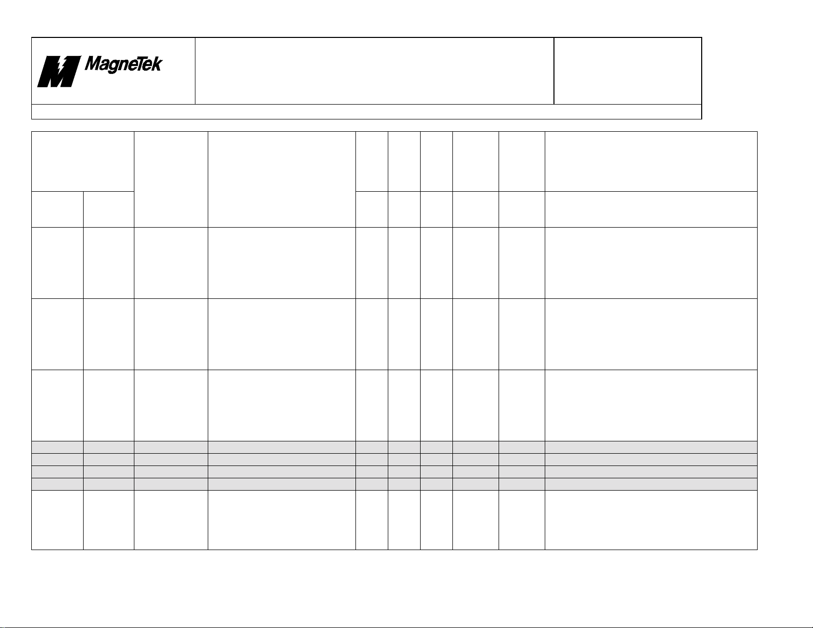
4. Function Blocks
The following section de tails fault numbers assigned to C la nguage function blocks.
Internal Fault #
Displayed Fault
No.
Fault Legend Description
Control
Node
Monitor
12AF8 76536 11000 No System
12AF9 76537 11001 Web Break The WEBB block has declared a web
12AFA 76538 11002 Ilegal Scan
Fault
Manager
Clock
Time
A ‘C’ language function block
(WEBB or DIAM_0) has made a
system call to get the present time
and the call returned indicating that
the time was not available. This
fault is declared by blocks that need
to know the present relative time to
perform their function.
break.
Either the RAMP, RAMP_1, SCRV
or SPDR_1 block has an illegal scan
time.
Display?
Priority
Newest
List?
No Yes Yes Minor
Yes Yes Yes Minor
Yes Yes Yes Minor
List?
Severity
Oldest
Rev. # 19 Page 21 of 64
Program
Assign
Input
Corrective Action
Minor
Major
Major
Some incompatibility may be happening
with the version of the operating system
and the downloaded program. The CPU
card may be defective.
Check web material for breakage or look
at logic output for same, and repair if
necessary.
The RAMP and RAMP_1 block cannot
operate with a scan time of less than
0.002 seconds; the SCRV block cannot
operate with a scan time of less than
0.0005 seconds. The SPDR_1 block
must have a scan time > 0.
The informatio n co ntained in this docum e nt is the CONFIDENTIAL property of MagneTek Inc.
File = N:\PROJECT\515\SmartTrac\DOCS\Faults.DOC Print Date: 10/17/00
21
Page 23

10/17/00
Smart Trac
Faults.doc
Product Development
New Berlin
Technology Center
Design
Title: Fault Declarations
Internal Fault #
Displayed Fault
No.
Fault Legend Description
Control
Node
Monitor
12AFB 76539 11003 Illegal Input The input to a block has an
12AFC 76540 11004 PG Illegal
12AFD 76541 11005 PG Illegal
Fault
Manager
Port
Chan
inappropriate input. The blocks
declaring this are CAVE, DAVE,
LDelay, NDelay, REFQ, TENR_1,
POSR_1, and POSR_2. These
function blocks expect parameter
inputs within a specified number
range.
( Note: this fault applies to
MAG_CPB libraries V1.8 and
older. )
The port setting to the
PG_ANALOG_IN, PG_DELTA_P,
or PG_TACH block is not one of the
legal values of 0, 1, 2 or 3.
The channel input setting to the
PG_TACH or PG_ANALOG_IN
block is not one of the legal values
of 0 or 1.
Document
Display?
Priority
Newest
List?
Yes Yes Yes Minor
Yes Yes Yes Minor
Yes Yes Yes Minor
List?
Severity
Oldest
Rev. # 19 Page 22 of 64
Program
Assign
Input
Corrective Action
FB_se
tup
Major
Major
Refer to block description Help in Smart
Trac AC1 Workstation software. Obey
these limits:
Samples for CAVE = 1 to 500;
Samples for DAVE = 1 to 1000;
Delays for LDelay = 1 to 500;
Delays for NDelay = 1 to 500;
REFQ CascadeNumber = 1 to
MaxCascadeNumber;
TENR_1 needs inputs for Webwidth,
WebThickness and TensionZoneLength.
POSR_1 Roll_Diameter > 1;
For POSR_2, all of these must be > 0:
RatedLineSpd, R1_Factor, R2_Factor,
RatedDancerStorage,
S_RPM_At_M_RPM,
POSR_0_ScanTime.
Port number is used to identify the PG
card. Note: older versions of the PG card
had legal values of 0 through 3. Newer
PG cards have only one port setting. Use
PortNumber = 1.
Use only channel 0 or channel 1. All
other values will cause this fault.
Reference drive schematic to set
correctly.
The informatio n co ntained in this docum e nt is the CONFIDENTIAL property of MagneTek Inc.
File = N:\PROJECT\515\SmartTrac\DOCS\Faults.DOC Print Date: 10/17/00
22
Page 24

10/17/00
Smart Trac
Faults.doc
New Berlin
Technology Center
Title: Fault Declarations
Internal Fault #
Displayed Fault
No.
Fault Legend Description
Control
Node
Monitor
12AFE 76542 11006 PG Card ID
12AFF 76543 11007 PG A/D
12B00 76544 11008 I/O Memory
Fault
Manager
Error
Retries
Alloc
Product Development
Design
Document
The PG card can’t be found. This is
due to the software not seeing the
correct identification code on the PG
card.
The PG_ANALOG_IN function
block senses that the PG card has not
done an analog to digital conversion
in the allotted time after the number
of attempts set by the TriesB4Fault
input to the PG_ANALOG_IN
block.
Dynamic RAM was not available for
use by one or more Function Blocks.
Display?
Priority
Newest
List?
Yes Yes Yes Minor
No Yes Yes Minor
Yes Yes Yes Minor
List?
Severity
Oldest
Rev. # 19 Page 23 of 64
Program
Assign
Input
Corrective Action
Major
Minor
Major
The correct PG card must be installed for
the Smart Trac AC1 function blocks
used.
Try increasing the number of attempts
for conversi on, TriesB4Fault, to a higher
value. Possibility the PG card is
defective.
These Functio n Blocks requi re use of
DRAM: CAVE, LDelay, NDelay, and
REFQ. One of these FBs was unable to
allocate memory to support its function.
Recycle power to Smart Trac AC1. If
problem persists, replace Smart Trac
CPU card.
The informatio n co ntained in this docum e nt is the CONFIDENTIAL property of MagneTek Inc.
File = N:\PROJECT\515\SmartTrac\DOCS\Faults.DOC Print Date: 10/17/00
23
Page 25

10/17/00
Smart Trac
Faults.doc
Product Development
New Berlin
Technology Center
Design
Document
Title: Fault Declarations
Internal Fault #
Displayed Fault
No.
Fault Legend Description
Control
Node
Monitor
12B01 76545 11009 TAPER Setup
12B02 76546 11010 PG_DELTA_
12B03 76547 11011 PG_DELTA_
12B04 76548 11012 FGEN5 Input The FGEN5 block declares this fault
12B05 76549 11013 LDel a y Inp u t An LDel a y fu nct io n blo c k has
Fault
Manager
Flt
P ID
P Setup
The TAPER block declares this fault
if input Tension Setpoint < 0, or
input Taper Ratio <=0, or input
Present Diameter <=0, or input Core
Diameter <= 0, or input Full Roll
Diameter <= input Core Diameter, or
input RatioAt20Percent_BU <=0, or
input RatioAt40Percent_BU <=0, or
input RatioAt60Percent_BU <=0, or
input RatioAt80Percent_BU <=0, or
input RatioAt100Percent_BU <= 0.
The PG Delta card can’t be found.
This is due to the software not seeing
the correct identification code on the
PG card which is used for
registration applications.
The PG_DELTA_P function block
declares this fault when the counter
start and stop source inputs are not in
the range from 1 to 4.
if input X_At_X5 is set to a value
less than or equal to input X_At_X0.
detected that its “Delays” input is
outside the valid range of 1 to 500.
Display?
Priority
Newest
List?
No Yes Yes Minor
Yes Yes Yes Minor
No Yes Yes Minor
No Yes Yes Minor
No Yes Yes Minor
List?
Severity
Oldest
Rev. # 19 Page 24 of 64
Program
Assign
Input
Corrective Action
FB_se
tup
Major
Minor
FB_se
tup
FB_se
tup
Change application program to meet the
following:
Tension Setpoint > 0,
Taper Ratio > 0,
Present Diameter > 0,
Core Diameter > 0,
Full Roll Diameter > Core Diam,
RatioAt20Percent_BU > 0,
RatioAt40Percent_BU > 0,
RatioAt60Percent_BU > 0,
RatioAt80Percent_BU > 0,
RatioAt100Percent_BU > 0.
The correct PG card must be installed for
the Smart Trac PG_DELTA_P function
block used.
Change input value(s) to counter start
input and stop source such that they fall
within the range of 1 through 4.
Set inputs such that
X_At_X5 > X_At_X0.
Review the LDelay functio n blo cks to
ensure all “Delays” inputs are within the
range of 1 to 500.
The informatio n co ntained in this docum e nt is the CONFIDENTIAL property of MagneTek Inc.
File = N:\PROJECT\515\SmartTrac\DOCS\Faults.DOC Print Date: 10/17/00
24
Page 26

10/17/00
Smart Trac
Faults.doc
Product Development
New Berlin
Technology Center
Design
Document
Title: Fault Declarations
Internal Fault #
Displayed Fault
No.
Fault Legend Description
Control
Node
Monitor
12B06 76550 11014 NDelay Input An NDelay function block has
12B07 76551 11015 REFQ Input A REFQ function block ha s detected
12B08 76552 11016 DIAM_2
12B09 76553 11017 INRT_1 Input An INRT_1 block has detected a
12B0A 76554 11018 CTCW_0
12B0B 76555 11019 CTCW_1
Fault
Manager
Input
Input
Input
detected that its “Delays” input is
outside the valid range of 1 to 500.
a “CascadeNumber” input >
“MaxCascadeNumber” input, or,
“MaxCascadeNumber” input does
not fall within a valid range of 1
through 255.
A DIAM_2 block has detected an out
of range value on one or more of its
inputs labeled RatedLineSpeed,
S_RPM_AT_M_RPM,
MaxDiameter, MinDiameter, or
NumberCalculation.
value of 0 on the RatedHorsepower
input.
A CTCW_0 block has detected a
value of 0 on its Diameter input
A CTCW_1 block has detected a
value of 0 on either the Horsepower
or the S_RPM_AT_M_RPM inputs.
Display?
Priority
Newest
List?
No Yes Yes Minor
No Yes Yes Minor
No Yes Yes Minor
No Yes Yes Minor
No Yes Yes Minor
No Yes Yes Minor
List?
Severity
Oldest
Rev. # 19 Page 25 of 64
Program
Assign
Input
Corrective Action
FB_se
tup
FB_se
tup
FB_se
tup
FB_se
tup
FB_se
tup
FB_se
tup
Review the NDelay function blocks to
ensure all “Delays” inputs are within the
range of 1 to 500.
Ensure the RE FQ function block has a
“CascadeNumber” input less than or
equal to “MaxCascadeNumber” input.
Ensure “MaxCascadeNumber” input
ranges from 1 to 255.
Ensure the DIAM_2 block has the proper
values at its inputs as follows:
RatedLineSpeed > 0,
S_RPM_AT_M_RPM > 0,
MinDiameter > 2 inches, or 5 cm,
MinDiameter <= MaxDiameter <= 99
inches, or 200 cm,
0 <= NumberCalculation <= 255.
Ensure the INRT_1 block has a positive,
non-zero value for its RatedHorsepower
input.
Ensure the CTCW_0 block has a
positive, non-zero value for its Diameter
input.
Ensure that the CTCW_1 block has
positive, non-zero values for both the
Horsepower and S_RPM_AT_M_RPM
inputs.
The informatio n co ntained in this docum e nt is the CONFIDENTIAL property of MagneTek Inc.
File = N:\PROJECT\515\SmartTrac\DOCS\Faults.DOC Print Date: 10/17/00
25
Page 27

10/17/00
Smart Trac
Faults.doc
Product Development
New Berlin
Technology Center
Design
Title: Fault Declarations
Internal Fault #
Displayed Fault
No.
Fault Legend Description
Control
Node
Monitor
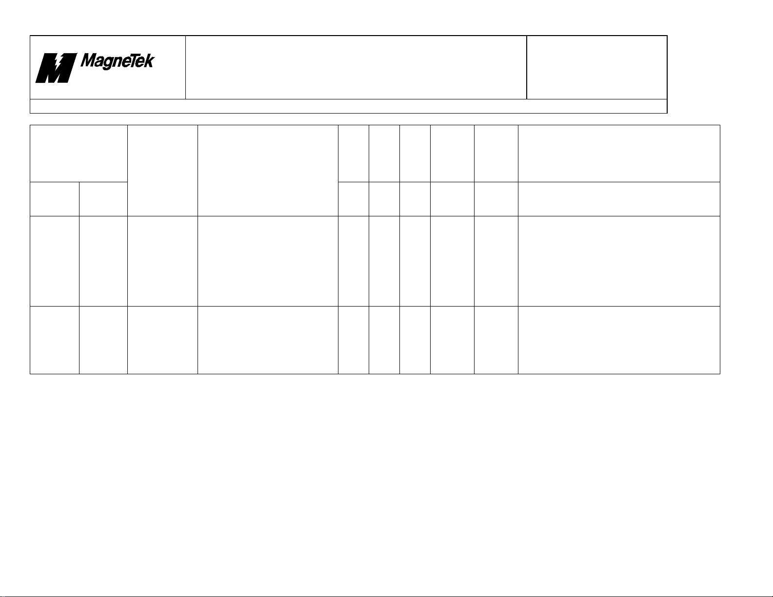
12B0C 76556 11020 PG_TACH
12B0D
to
12B5B
12B5C 76636 11100 Tach Loss The TMON block has detected a
12B5D 76637 11101 Reverse Tach
12B5E 76638 11102 Fwd
Fault
Manager
76557 to
76635
11021
to
11099
Input
Not Used
Flt
Overspeed
A PG_TACH or PG_TACH2 block
has detected a value of 0 on the
TachCounts or RatedSpeed inputs.
tachometer (encoder) loss.
The TMON block has detected a
reversed tachometer (encoder)
connection.
The TMON block has detected an
overspeed condition in the forward
direction.
Document
Display?
Priority
Newest
List?
No Yes Yes Minor
Yes Yes Yes Minor
Yes Yes Yes Minor
Yes Yes Yes Minor
List?
Severity
Oldest
Rev. # 19 Page 26 of 64
Program
Assign
Input
Corrective Action
FB_se
tup
Major
Major
Major
Ensure the PG_TACH or PG_TACH2
block has non-zero values for the
TachCounts and RatedSpeed inputs.
Check wiring from encoder to PG card.
Tach loss occurs when AuxSpeedSense
> (AuxSenseLevel / 100) and
TachometerInput < (TachSenseLevel /
100).
Change wiring from encoder to PG card.
Declared when AuxSpeedSense >
(AuxSenseLevel / 100) AND
(ReferenceInput > 0 and
TachometerInput < 0) OR
(ReferenceInput < 0 and
TachometerInput > 0).
Motor speed has exceeded the forward
setpoint: TachometerInput >
(FwdOverspeedLimit / 100). Reduce
commanded speed or load if runaway
condition exists.
The informatio n co ntained in this docum e nt is the CONFIDENTIAL property of MagneTek Inc.
File = N:\PROJECT\515\SmartTrac\DOCS\Faults.DOC Print Date: 10/17/00
26
Page 28

10/17/00
Smart Trac
Faults.doc
Product Development
New Berlin
Technology Center
Design
Document
Title: Fault Declarations
Internal Fault #
Displayed Fault
No.
Fault Legend Description
Control
Node
Monitor
12B5F 76639 11103 Rev
12B60 76640 11104 TENR Input A TENR function block has detected
12B61 76641 11105 SCRV Input A SCRV function block has detected
12B62 76642 11106 DAVE Input A DAVE function block has detected
Fault
Manager
Overspeed
The TMON block has detected an
overspeed condition in the reverse
direction.
a value of zero for any one of these
inputs: TensionZoneLength,
WebWidth, WebThickness, or
YoungsModulus.
a negative value for one of these
inputs: Accel_Time, Decel_Time,
Accel_Jrk_Percent,
Decel_Jrk_Percent.
an out of range value at its
“NumberOfSamples” input.
Display?
Priority
Newest
List?
Yes Yes Yes Minor
No Yes Yes Minor
No Yes Yes Minor
No Yes Yes Minor
List?
Severity
Oldest
Rev. # 19 Page 27 of 64
Program
Assign
Input
Corrective Action
Major
FB_se
tup
FB_se
tup
FB_se
tup
Motor speed has exceeded the reverse
setpoint: TachometerInput <
(RevOverspeedLimit / 100). Reduce
commanded speed or load if runaway
condition exists.
Ensure that the TENR function block has
non-zero values at TensionZoneLength,
WebWidth, WebThickness or
YoungsModulus inputs. Note that a
function block uses a value of ‘0’ when
an input is left unconnected.
Ensure that the SCRV block has
Accel_Time, Decel_Time,
Accel_Jrk_Percent, and
Decel_Jrk_Percent input values are
greater than or equal to zero.
Ensure that the DAVE function blocks
use values from 1 to 500 at their
“NumberOfSamples” inputs.
The informatio n co ntained in this docum e nt is the CONFIDENTIAL property of MagneTek Inc.
File = N:\PROJECT\515\SmartTrac\DOCS\Faults.DOC Print Date: 10/17/00
27
Page 29

10/17/00
Smart Trac
Faults.doc
New Berlin
Technology Center
Title: Fault Declarations
Internal Fault #
Displayed Fault
No.
Fault Legend Description
Control
Node
Monitor
12B63 76643 11107 CAVE Input
12B64 76644 11108 POSR_1
12B65 76645 11109 POSR_2
Fault
Manager
Input
Input
Product Development
Design
Document
A CAVE function block has
detected an out of range value at
its "NumberOfSamples" or
"MaxNumberOfSamples" input, or
an infinite or NaN value at its
"InputSignal" in put.
A POSR_1 function block has
detected an out of range value at its
“Roll_Diameter” input or its
RetainMaxValue input is equal to its
RetainMinValue input.
A POSR_2 function block has
detected an out of range value for
one of its inputs labeled
“RatedLineSpd”,
“S_RPM_At_M_RPM”,
“RatedDancerStorage”, “R1_Factor”,
or “R2_Factor”.
Display?
Priority
Newest
List?
No Yes Yes Minor
No Yes Yes Minor
No Yes Yes Minor
List?
Severity
Oldest
Rev. # 19 Page 28 of 64
Program
Assign
Input
Corrective Action
FB_se
tup
FB_se
tup
FB_se
tup
Ensure that the CAVE function block
uses a range of 1 to 500 for
“MaxNumberOfSamples” input and
“NumberOfSamples” <
“MaxNumberOfSamples”. Ensure that
the value at "InputSigna l" is not
infinity or NaN (Not A Number).
Infinity can be created by dividing by
zero or taking the logarithm of 0.
NaN values can be created with
equations such as square root of a
negative number or zero divided by
zero.
Ensure that the POSR_1 function block
uses a value for its “Roll_Diameter”
input > 1. Ensure that the Dancer Signal
has been calibrated (i.e. its
RetainMinValue and RetainMaxValue
must both no t equal zero ).
Ensure that the POSR_2 function block
inputs labeled “RatedLineSpd”,
“S_RPM_At_M_RPM”,
“RatedDancerStorage”, “R1_Factor”,
and “R2_Factor” have values > 0.
The informatio n co ntained in this docum e nt is the CONFIDENTIAL property of MagneTek Inc.
File = N:\PROJECT\515\SmartTrac\DOCS\Faults.DOC Print Date: 10/17/00
28
Page 30

10/17/00
Smart Trac
Faults.doc
Product Development
New Berlin
Technology Center
Design
Document
Title: Fault Declarations
Internal Fault #
Displayed Fault
No.
Fault Legend Description
Control
Node
Monitor
12B66 76646 11110 GEAR Input A GEAR function block has detected
12B67 76647 11111 POSR_0
Fault
Manager
Input
a value of ‘0’ for its
“InputGear_Denominator” input.
A POSR_0 function block has
calculated an out of range value for
its “DancerOut” output.
“DancerOut” is the “DancerSignal”
modified by a SPAN and ZERO
adjustments provided by
corresponding the POSR_1 function
block. “DancerOut” is a per-unit
number and this fault is declared if
“DancerOut” calculates as less than
-0.1 or greater than +1.1.
Display?
Priority
Newest
List?
No Yes Yes Minor
No Yes Yes Minor
List?
Severity
Oldest
Rev. # 19 Page 29 of 64
Program
Assign
Input
Corrective Action
FB_se
tup
FB_se
tup
Ensure that the GEAR function block
input(s) “InputGear_Denominator” is not
set to zero.
Ensure that the DancerSignal of the
corresponding POSR_1 function block
has been calibrated. Ensure that the
dancer feedback mechanism has not
moved. The dancer signal in the
corresponding POSR_1 function block
may need recalibration.
The informatio n co ntained in this docum e nt is the CONFIDENTIAL property of MagneTek Inc.
File = N:\PROJECT\515\SmartTrac\DOCS\Faults.DOC Print Date: 10/17/00
29
Page 31

10/17/00
Smart Trac
Faults.doc
Product Development
New Berlin
Technology Center
Design
Document
Title: Fault Declarations
5. Drivers
5.1 DPRAM Driver
The following section details fault numbers assi gned to Dual Port RAM.
Internal Fault #
Displayed Fault
No.
Fault Legend Description
Control
Node
Monitor
14E20 85536 20000 DPRAM HS Resp High Speed response
14E21 85537 20001 DPRAM HS Cmd High Speed co mmand
14E22 85538 20002 DPRAM Response DPRAM response handshake
14E23 85539 20003 DPRAM Co mma nd DPRAM command
Fault
Manager
handshake fault between the
Smart Trac AC1 CPU card
and the inverter control card.
handshake fault between the
Smart Trac AC1 CPU card
and the inverter control card.
fault between the Smart Trac
AC1 CPU card and the
inverter control card.
handshake fault between the
Smart Trac AC1 CPU card
and the inverter control card.
Display?
Priority
Newest
List?
No Yes Yes Minor
Yes Yes Yes Minor
No Yes Yes Minor
No Yes Yes Minor
Oldest
List?
Severity
Rev. # 19 Page 30 of 64
Program
Assign
Input
Minor
Major
Minor
Minor
High Speed data such as torque reference
and motor speed cannot be obtained from
the inverter card. Recycle drive power. If
problem persists, consult the factory.
High Speed command information such as
Run/Stop cannot be sent to the inverter
card. Drive must be stopped by externallywired E-stop. Recycle drive power. If
problem persists, consult the factory.
Inverter parameters such as ‘Accel Time 1’
cannot be obtained from the inverter card.
Recycle drive power. If problem persists,
consult the factory.
Cannot send parameters values from Smart
Trac drive’s CPU card to inverter card.
Recycle drive power. If problem persists,
consult the factory. Note: there are some
critical parameters that cannot be changed
during Run.
Corrective Action
The informatio n co ntained in this docum e nt is the CONFIDENTIAL property of MagneTek Inc.
File = N:\PROJECT\515\SmartTrac\DOCS\Faults.DOC Print Date: 10/17/00
30
Page 32

10/17/00
Smart Trac
Faults.doc
Product Development
New Berlin
Technology Center
Design
Title: Fault Declarations
Internal Fault #
Displayed Fault
No.
Fault Legend Description
Control
Node
Monitor
14E24 85540 20004 DPRAM Address DPRAM bad address or
14E25 85541 20005 DPRAM Param
14E26 85542 20006 DPRAM Parm
14E27 85543 20007 DPRAM Chg @
Fault
Manager
Num
Range
Run
register requested fault
between the Smart Trac AC1
CPU card and the inverter
control card.
Bad number of parameters
requested from Dual Port
RAM of the Smart Trac AC1
CPU card (to inverter control
card).
Bad parameter data specified
between the Smart Trac AC1
CPU card and the inverter
control card. Parameter
setting sent to inverter is out
of range for that inverter.
Dual Port RAM non-run
inverter parameter change
requested between the Smart
Trac AC1 CPU card and the
inverter control card while
the inverter is running.
Document
Display?
Priority
Newest
List?
Yes Yes Yes Minor
Yes Yes Yes Minor
No Yes Yes Minor
No Yes Yes Minor
Oldest
List?
Severity
Rev. # 19 Page 31 of 64
Program
Assign
Input
Major
Major
Minor
Minor
Check for correct inverter model number;
don’t forget to initialize the inverter card if
model number was changed. Make sure t he
inverter Control Method is set to ‘Flux
Vector’ (typical).
The Smart Trac main CPU card may be
faulty. If available, download a small test
program to see if fault persists.
Check for correct inverter model number;
don’t forget to initialize the inverter card if
model number was changed. Look for
obvious mistakes in the application
program such as attempting to alter
inverter current settings. Make sure t he
inverter Control Method is set to ‘Flux
Vector’ (typical).
Certain parameters cannot be changed
while the inverter is running a motor.
Application program should be structured
to avoid writes to these parameters during
Run conditions.
Corrective Action
The informatio n co ntained in this docum e nt is the CONFIDENTIAL property of MagneTek Inc.
File = N:\PROJECT\515\SmartTrac\DOCS\Faults.DOC Print Date: 10/17/00
31
Page 33

10/17/00
Smart Trac
Faults.doc
New Berlin
Technology Center
Title: Fault Declarations
Internal Fault #
Displayed Fault
No.
Fault Legend Description
Control
Node
Monitor
14E28 85544 20008 DPRAM Write@
14E29 85545 20009 DPRAM
14E2A 85546 20010 DPRAM Unknwn
14E2B 85547 20011 DP RAM T ref
Fault
Manager
UV
Write@Calc
Rsp
Hndsk
Product Development
Design
Document
Dual Port RAM write
requested between the Smart
Trac AC1 CPU card and the
inverter control card while
there is an undervoltage fault
Dual Port RAM write
requested between the Smart
Trac AC1 CPU card and the
inverter control card, while a
parameter is being calculated.
Unknown Dual Port RAM
response between the Smart
Trac AC1 CPU card and the
inverter control card.
Dual Port RAM 2ms Torque
Reference handshake fault
between the Smart Trac AC1
CPU card and the inverter
control card.
Display?
Priority
Newest
List?
No Yes Yes Minor
No Yes Yes Minor
Yes Yes Yes Minor
Yes Yes Yes Minor
Oldest
List?
Severity
Rev. # 19 Page 32 of 64
Program
Assign
Input
Minor
Minor
Major
Major
and
Minor
Correct undervoltage issue – check quality
of AC power supply.
The inverter card continually performs
background calculations on internal
parameters. If this fault persists, consult
the factory.
Smart Trac AC1 CPU card received
information from inverter card that is
incorrect. Inverter firmware may be wrong
version or inverter card may be defective.
Check integrity of physical connecti on
between Smart Trac AC1 CPU card and
inverter card. Check Inverter Type in Boot
menu: for most cases, value should be set
for 2 ms Torq Update. Application
program may be overburdened – reduce
amount of logic placed in fast Tasks (15ms
or faster) to slow Tasks (30ms or slo wer).
Corrective Action
The informatio n co ntained in this docum e nt is the CONFIDENTIAL property of MagneTek Inc.
File = N:\PROJECT\515\SmartTrac\DOCS\Faults.DOC Print Date: 10/17/00
32
Page 34

10/17/00
Smart Trac
Faults.doc
Product Development
New Berlin
Technology Center
Design
Document
Title: Fault Declarations
5.2 STLAN Driver
The following section details fault numbers assigned to Smart Trac AC1 Local Area Network (ARCNET).
Internal Fault #
Displayed Fault
No.
Fault Legend Description
Control
Node
Monitor
14EE8 85736 20200 LAN Hardware
14EE9 85737 20201 LAN Max Tx Flt LAN - max number of
14EEA 85738 20202 LAN Illegal Msg LAN - illegal message
14EEB 85739 20203 LAN Missed
14EEC 85740 20204 LAN Missed
14EED 85741 20205 LAN No Tx
14EEE 85742 20206 LAN No Rx
Fault
Manager
Flt
Bcast
Dirct
Room
Room
LAN hardware fault. Yes Yes Yes Minor
transmit attempts
exceeded.
type.
LAN missed a
broadcast message.
LAN missed a directed
message.
LAN - no room to
transmit message.
LAN - no room to
receive message.
Display?
Priority
Newest
List?
No Yes Yes Minor
No Yes Yes Minor
No Yes Yes Minor
No Yes Yes Minor
No Yes Yes Minor
No Yes Yes Minor
Oldest
List?
Severity
Input
Program
Major
Minor
Minor
Minor
Minor
Minor
Minor
Rev. # 19 Page 33 of 64
Assign
Corrective Action
ARCNET card is defective or not installed
properly.
Attempting to transmit LAN messages to a
channel or node that isn’t active or doesn’t
exist.
Message is not supported by STLAN
Interface Card.
Excessive amount of LAN traffic. Reduce
number of messages being sent/received.
May have too many nodes on the network –
use an ARCNET active hub to buffer
messages.
Excessive amount of LAN traffic. Reduce
number of messages being sent/received.
May have too many nodes on the network –
use an ARCNET active hub to buffer
messages.
Excessive amount of LAN traffic. Reduce
number of messages being sent/received.
Excessive amount of LAN traffic. Reduce
number of messages being sent/received.
The informatio n co ntained in this docum e nt is the CONFIDENTIAL property of MagneTek Inc.
File = N:\PROJECT\515\SmartTrac\DOCS\Faults.DOC Print Date: 10/17/00
33
Page 35

10/17/00
Smart Trac
Faults.doc
New Berlin
Technology Center
Title: Fault Declarations
Internal Fault #
Displayed Fault
No.
Fault Legend Description
Control
Node
Monitor
14EEF 85743 20207 LAN Rem Out
14EF0 85744 20208 LAN Rem Num
Fault
Manager
Time
In
Product Development
Design
Remote No Output
Command Fault – This
message is sent from a
remote I/O node when
it does not receive an
output co mmand LAN
message from a Smart
Trac AC1 drive, that
has allocated one or
more outputs, within
the prescribed time.
Numeric Input
Request Fault – This
message is sent from
the remote I/O node to
the Smart Trac AC1
drive when the remote
I/O node cannot
provide a digital
numeric input to the
drive for reasons other
than LAN failure.
Document
Display?
Priority
Newest
List?
No Yes Yes Minor
No Yes Yes Minor
Oldest
List?
Severity
Input
Program
Minor
Minor
Rev. # 19 Page 34 of 64
Assign
Corrective Action
Possibility that a supporting Task in Smart
Trac AC1 has encountered a fault.
A typical reason for this condition might be
that there is no digital numeric input module
located at the given channel/subchannel.
The informatio n co ntained in this docum e nt is the CONFIDENTIAL property of MagneTek Inc.
File = N:\PROJECT\515\SmartTrac\DOCS\Faults.DOC Print Date: 10/17/00
34
Page 36

10/17/00
Smart Trac
Faults.doc
Product Development
New Berlin
Technology Center
Title: Fault Declarations
Internal Fault #
Displayed Fault
No.
Fault Legend Description
Control
Node
Monitor
14EF1 85745 20209 LAN Rem LogicInLogic Input Request
14EF2 85746 20210 LAN Rem Num
Fault
Manager
Out
Fault – This message
is sent from the remote
I/O node to the Smart
Trac AC1 drive when
the remote I/O node
cannot provide a
logical input for
reasons other than
LAN failure.
Numeric Output
Allocation Fault – The
requested numeric
output allocation could
not take place because
of an allocation
conflict with another
device or the absence
of the device(s) being
requested.
Design
Document
Display?
Priority
Newest
List?
No Yes Yes Minor
No Yes Yes Minor
Oldest
List?
Severity
Input
Program
Minor
Minor
Rev. # 19 Page 35 of 64
Assign
Corrective Action
A typical reason for this condition might be
there is no logic I/O channel located at the
given channel.
Check for duplicate LAN node, channel and
subchannel in drive programs. Possible
incorrect setting of node channel or
subchannel at remote device.
The informatio n co ntained in this docum e nt is the CONFIDENTIAL property of MagneTek Inc.
File = N:\PROJECT\515\SmartTrac\DOCS\Faults.DOC Print Date: 10/17/00
35
Page 37

10/17/00
Smart Trac
Faults.doc
New Berlin
Technology Center
Title: Fault Declarations
Internal Fault #
Displayed Fault
No.
Fault Legend Description
Control
Node
Monitor
14EF3 85747 20211 LAN Rem
Fault
Manager
LogicOut
Product Development
Design
Logic Output
Allocation Fault -The
requested logic output
allocation could not
take place because of
an allocation conflict
with another device or
the absence of the
device(s) being
requested.
Document
Display?
Priority
Newest
List?
No Yes Yes Minor
Oldest
List?
Severity
Input
Program
Minor
Rev. # 19 Page 36 of 64
Assign
Corrective Action
Check for duplicate LAN node, channel and
subchannel in drive programs. Check that
the node, channel, and subchannel exists for
remote I/O devices.
The informatio n co ntained in this docum e nt is the CONFIDENTIAL property of MagneTek Inc.
File = N:\PROJECT\515\SmartTrac\DOCS\Faults.DOC Print Date: 10/17/00
36
Page 38

10/17/00
Smart Trac
Faults.doc
Product Development
New Berlin
Technology Center
Design
Document
Title: Fault Declarations
5.3 Operator Driver
The following section details fault numbers assigned to JVOP-130 Digital Operator.
Notes:
• As of this print date, no Operator faults exist.
• TBD = To Be Determined.
Internal Fault #
Displayed Fault
No.
Control
Node
Monitor
14FB0 85936 20400 DigOp TBD Minor TBD TBD
14FB1 85937 20401 DigOp TBD Minor TBD TBD
14FB2 85938 20402 DigOp TBD Minor TBD TBD
14FB3 85939 20403 DigOp TBD Minor TBD TBD
14FB4 85940 20404 DigOp TBD Minor TBD TBD
14FB5 85941 20405 DigOp TBD Minor TBD TBD
14FB6 85942 20406 DigOp TBD Minor TBD TBD
Fault
Manager
Fault
Legend
Description
Display?
Priority
List?
Newest
Severity
Oldest
List?
Program
Input
Assign
Rev. # 19 Page 37 of 64
Corrective Action
The informatio n co ntained in this docum e nt is the CONFIDENTIAL property of MagneTek Inc.
File = N:\PROJECT\515\SmartTrac\DOCS\Faults.DOC Print Date: 10/17/00
37
Page 39

10/17/00
Smart Trac
Faults.doc
Rev. # 19 Page 38 of 64
New Berlin
Technology Center
Product Development
Design
Document
Title: Fault Declarations
6. Inverter
The following section details fault numbers assigned to the Smart Trac AC1 Inverter (Power Conversion Unit).
Notes:
• Inverter faults will be declared only if properly setup in Fault Manager, DPRAM Interface Card, and the application program.
• These faults are declared when the inverter sees them as major faults. As Minor faults, these fault codes are not generated but drive may still set a minor fault bit.
• All Inverter faults listed here correspond to those found in MagneTek’s GPD515 Technical Manual.
Displayed Fault
No.
Control
Node
Monitor
17530 95536 30000 DC Bus Fuse Open PUF – Fuse blown. DC f use has
17531 95537 30001 DC Bus Undervolt UV1 – Main circuit undervoltage.
17532 95538 30002 CTL PS Undervolt UV2 – Control circuit undervoltage.
Fault
Manager
Internal Fault
No.
Fault Legend Description
cleared.
Occurs 2 seconds after detection of
low voltage. Detection levels:
190VDC for 230V rated unit;
380VDC for 460V rated unit;
546VDC for 600V rated unit.
Control circuit voltage is low during
operation.
Display?
Priority
Newest
List?
Yes Yes Yes Minor
Yes Yes Yes Minor
Yes Yes Yes Minor
Oldest
List?
Severity
Program
Input
Major
Major
Major
Assign
Corrective Action
Check for short circuit in output
circuitry. Possibility of motor
windings T1, T2 and/or T3 shorted.
Possibility of drive output phases
shorted to ground. Possibility power
transistors are d amaged.
Check input AC supply. Possib ility
of erroneous operation due to noise:
remove noise source by connecting
surge suppressor to relay and
magnetic contactor coils; provide line
filter to remove noise on input power
line. Possibility of gate drive PCB is
faulty. Note: fault is declared only if
drive is in Run mode.
Possibility of poor DC supply being
furnished by drive. Note: fault is
declared only if drive is in Run
mode.
The informatio n co ntained in this docum e nt is the CONFIDENTIAL property of MagneTek Inc.
File = N:\PROJECT\515\SmartTrac\DOCS\Faults.DOC Print Date: 10/17/00
38
Page 40

10/17/00
Smart Trac
Faults.doc
Product Development
New Berlin
Technology Center
Design
Document
Title: Fault Declarations
Displayed Fault
No.
Control
Node
Monitor
17533 95539 30003 MC Answerback UV3 – Main contactor fault. Main
17534 95540 30004 Short Circuit SC – Short circuit on Smart Trac
17535 95541 30005 G round Fault GF – Ground fault. Drive o ut put
17536 95542 30006 Overcurrent OC – Overcurrent. Output current
Fault
Manager
Internal Fault
No.
Fault Legend Description
circuit magnetic contactor (soft
charge contactor) does not operate
correctly.
AC1 inverter PCB output terminals
(motor wiring).
ground current exceeded 50% of
drive rated current.
exceeded 200% of drive rated
current.
Display?
Priority
Newest
List?
Yes Yes Yes Minor
Yes Yes Yes Minor
Yes Yes Yes Minor
Yes Yes Yes Minor
Oldest
List?
Severity
Rev. # 19 Page 39 of 64
Program
Assign
Input
Corrective Action
Major
Major
Major
Major
Check contactor wiring. Inspect
contactor for damage and defects.
Note: fault is declared only if drive is
in Run mode.
Check for correct motor
wiring/capacity. Note: fault is
declared only if drive is in Run
mode.
Check for correct motor
wiring/capacity. Look for shorts
between motor leads and ground.
Inverter power transistor(s) may be
damaged. Note: fault is declared only
if drive is in Run mode.
Acceleration time may be set too
low. Motor load may be too great for
drive to handle. Motor may be
jammed or defective. Note: fault is
declared only if drive is in Run
mode.
The informatio n co ntained in this docum e nt is the CONFIDENTIAL property of MagneTek Inc.
File = N:\PROJECT\515\SmartTrac\DOCS\Faults.DOC Print Date: 10/17/00
39
Page 41

10/17/00
Smart Trac
Faults.doc
Product Development
New Berlin
Technology Center
Design
Document
Title: Fault Declarations
Displayed Fault
No.
Control
Node
Monitor
17537 95543 30007 DC Bus Overvolt OV – Overvoltage. Detection levels:
17538 95544 30008 Heatsnk Overtemp OH – Cooling fin overheat.
17539 95545 30009 Heatsnk MAX
Fault
Manager
Internal Fault
No.
Temp
Fault Legend Description
400VDC for 230V rated unit;
800VDC for 460V rated unit;
1050VDC for 600V rated unit.
Heatsink fin temperature exceeded
preset value found in inverter
parameter L8-02.
OH1 – Drive overheat. Heatsink fin
temperature exceeded 105˚ C (221˚
F).
Display?
Priority
Newest
List?
Yes Yes Yes Minor
Yes Yes Yes Minor
Yes Yes Yes Minor
Oldest
List?
Severity
Rev. # 19 Page 40 of 64
Program
Assign
Input
Corrective Action
Major
Minor
Major
Check input AC supply. Possib ility
of erroneous operation due to noise:
remove noise source by connecting
surge suppressor to relay and
magnetic contactor coils; provide line
filter to remove noise on input power
line. If OV trip occurs during
deceleration, increase deceleration
time; may need dynamic braking
option. Note: fault is declared only if
drive is in Run mode.
Major fault declared only if inverter
parameter L8-03 ≠ 3. Reduce
ambient temperature to less than
45˚C (113˚ F). Clean heat sink.
Replace cooling fan if necessary.
Reduce ambient temperature to less
than 45˚C (113˚ F). Clean heat sink.
Replace cooling fan if necessary.
The informatio n co ntained in this docum e nt is the CONFIDENTIAL property of MagneTek Inc.
File = N:\PROJECT\515\SmartTrac\DOCS\Faults.DOC Print Date: 10/17/00
40
Page 42

10/17/00
Smart Trac
Faults.doc
Product Development
New Berlin
Technology Center
Design
Document
Title: Fault Declarations
Displayed Fault
No.
Control
Node
Monitor
1753A 95546 30010 Motor Overloaded OL1 – Motor overload. Protects the
1753B 95547 30011 Inv Overloaded OL2 – Drive overload. Protects the
1753C 95548 30012 Overtorque Det 1 OL3 – Overtorque detect 1. Output
1753D 95549 30013 Overtorque Det 2 OL4 – Overtorque detect 2. Output
1753E 95550 30014 DynBr k Transistr RR – Dynamic braking transi stor
Fault
Manager
Internal Fault
No.
Fault Legend Description
motor. Motor thermal overload
protection has tripped. Inverter
parameter L1-02 has been exceeded
(initial value: 150% for 60 sec.).
Smart Trac AC1 drive. Drive
overload protection has tripped.
current exceeded Overtorque
Detection Level 1 set in inverter
parameter L6-02.
current exceeded Overtorque
Detection Level 2 set in inverter
parameter L6-05.
failure.
Display?
Priority
Newest
List?
Yes Yes Yes Minor
Yes Yes Yes Minor
Yes Yes Yes Minor
Yes Yes Yes Minor
Yes Yes Yes Minor
Oldest
List?
Severity
Rev. # 19 Page 41 of 64
Program
Assign
Input
Corrective Action
Major
Major
Major
Major
Major
Major fault is declared if L1-01 = 1.
Load may be too large. Check drive
capacity (inverter parameter o2-04)
for correct factory setting. Check for
proper setting of electronic thermal
overload setting: inverter parameters
E1-02, E2-01, L1-02. Try
disconnect in g moto r wiri ng fr om
output terminals – if OL is still
indicated, problem may be due to
noise or faulty inverter cards
See fault “Motor Overloaded” for
details.
Declared only if inverter parameter
L6-01= 3 or 4. Reduce load, increase
acceleration time, or increase inverter
parameter setting L6-02.
Declared only if inverter parameter
L6-04= 3 or 4. Reduce load, increase
acceleration time, or increase inverter
parameter setting L6-05.
Replace dynamic braking unit.
The informatio n co ntained in this docum e nt is the CONFIDENTIAL property of MagneTek Inc.
File = N:\PROJECT\515\SmartTrac\DOCS\Faults.DOC Print Date: 10/17/00
41
Page 43

10/17/00
Smart Trac
Faults.doc
Product Development
New Berlin
Technology Center
Design
Document
Title: Fault Declarations
Displayed Fault
No.
Control
Node
Monitor
1753F 95551 30015 DynBrk Resistor RH – Dynamic braking r esistor
17540 95552 30016 External Fault 3 EF3 – External fault signal at
17541 95553 30017 External Fault 4 EF4 – External fault signal at
17542 95554 30018 External Fault 5 EF5 – External fault signal at
Fault
Manager
Internal Fault
No.
Fault Legend Description
overheat. Braking resistor unit
temperature exceeded allowable
value. (Heatsink-mount resistor
only, and only if inverter parameter
L8-01 = 1).
terminal 3 of the inverter card. This
can be programmed to be N.O. or
N.C. contact.
terminal 4 of the inverter card. This
can be programmed to be N.O. or
N.C. contact.
terminal 5 of the inverter card. This
can be programmed to be N.O. or
N.C. contact.
Display?
Priority
Newest
List?
Yes Yes Yes Minor
Yes Yes Yes Minor
Yes Yes Yes Minor
Yes Yes Yes Minor
Oldest
List?
Severity
Rev. # 19 Page 42 of 64
Program
Assign
Input
Corrective Action
Major
Major
Major
Major
Allow dynamic braking resistors to
cool before continui ng operatio n. If
problem persists, decrease load sizes
or reevaluate dynamic braking
requirements.
A fault has occurred in circuits
outside the Smart Trac AC1 inverter
card. Troubleshoot and correct. The
input labeled ‘Major’ will be true
only if inverter parameter H1-01 = 20
to 2B hex.
A fault has occurred in circuits
outside the Smart Trac AC1 inverter
card. Troubleshoot and correct. The
input labeled ‘Major’ will be true
only if inverter parameter H1-02 = 20
to 2B hex.
A fault has occurred in circuits
outside the Smart Trac AC1 inverter
card. Troubleshoot and correct. The
input labeled ‘Major’ will be true
only if inverter parameter H1-03 = 20
to 2B hex.
The informatio n co ntained in this docum e nt is the CONFIDENTIAL property of MagneTek Inc.
File = N:\PROJECT\515\SmartTrac\DOCS\Faults.DOC Print Date: 10/17/00
42
Page 44

10/17/00
Smart Trac
Faults.doc
Product Development
New Berlin
Technology Center
Design
Document
Title: Fault Declarations
Displayed Fault
No.
Control
Node
Monitor
17543 95555 30019 External Fault 6 EF6 – External fault signal at
17544 95556 30020 External Fault 7 EF7 – External fault signal at
17545 95557 30021 External Fault 8 EF8 – External fault signal at
17546 95558 30022 Not used
Fault
Manager
Internal Fault
No.
Fault Legend Description
terminal 6 of the inverter card. This
can be programmed to be N.O. or
N.C. contact.
terminal 7 of the inverter card. This
can be programmed to be N.O. or
N.C. contact.
terminal 8 of the inverter card. This
can be programmed to be N.O. or
N.C. contact.
Display?
Priority
Newest
List?
Yes Yes Yes Minor
Yes Yes Yes Minor
Yes Yes Yes Minor
Oldest
List?
Severity
Rev. # 19 Page 43 of 64
Program
Assign
Input
Corrective Action
Major
Major
Major
A fault has occurred in circuits
outside the Smart Trac AC1 inverter
card. Troubleshoot and correct. The
input labeled ‘Major’ will be true
only if inverter parameter H1-04 = 20
to 2B hex.
A fault has occurred in circuits
outside the Smart Trac AC1 inverter
card. Troubleshoot and correct. The
input labeled ‘Major’ will be true
only if inverter parameter H1-05 = 20
to 2B hex.
A fault has occurred in circuits
outside the Smart Trac AC1 inverter
card. Troubleshoot and correct. The
input labeled ‘Major’ will be true
only if inverter parameter H1-06 = 20
to 2B hex.
The informatio n co ntained in this docum e nt is the CONFIDENTIAL property of MagneTek Inc.
File = N:\PROJECT\515\SmartTrac\DOCS\Faults.DOC Print Date: 10/17/00
43
Page 45

10/17/00
Smart Trac
Faults.doc
Product Development
New Berlin
Technology Center
Design
Document
Title: Fault Declarations
Displayed Fault
No.
Control
Node
Monitor
17547 95559 30023 Overspeed OS – Motor overspeed. Motor speed
17548 95560 30024 Speed Deviation DEV – Speed deviation. Difference
17549 95561 30025 PG Open PGO – PG cable wires are
1754A 95562 30026 Input Pha Loss PF – Inverter input phase missing.
Fault
Manager
Internal Fault
No.
Fault Legend Description
exceeded overpspeed level set by
inverter parameters F1-08, F1-09.
between speed reference and speed
feedback exceeded the deviation
level set in inverter parameters F110, F1-11.
disconnected, bad tach, tach is not
connected to motor, or missing tach
power supply. This is actually a
tach loss condition.
Incoming power supply has an open
phase, or a large imbalance exists
between L1, L2, and L3.
Display?
Priority
Newest
List?
Yes Yes Yes Minor
Yes Yes Yes Minor
Yes Yes Yes Minor
Yes Yes Yes Minor
Oldest
List?
Severity
Rev. # 19 Page 44 of 64
Program
Assign
Input
Corrective Action
Major
Major
Major
Major
Check for correct tach (encoder) PPR
value in inverter parameter F1-01.
May have excessive noise on encoder
signal inputs to Smart Trac AC1
drive. Consult MagneTek about
specifications of user-supplied
encoder. Major fault declared only if
inverter parameter F1-03 ≠ 3, else a
minor faul t.
Decrease load, increase
acceleration/deceleration times, or
increase deviation levels found at
inverter parameters F1-10, F1-11.
The input labeled ‘Major’ will be set
only if inverter parameters A1-02 = 1
or 3, and d5-01 = 0, and F1-04 ≠ 3.
Connect wires from the Smart Trac
AC1 PG card to encoder, or look for
damaged wires. The input labeled
‘Major’ will be set only if inverter
parameters A1-02 = 1 or 3, and d5-01
= 0, and F1-02 ≠ 3.
Check input AC supply. Note:
inverter parameter L8-05 = 1 enables
this fault.
The informatio n co ntained in this docum e nt is the CONFIDENTIAL property of MagneTek Inc.
File = N:\PROJECT\515\SmartTrac\DOCS\Faults.DOC Print Date: 10/17/00
44
Page 46

10/17/00
Smart Trac
Faults.doc
Product Development
New Berlin
Technology Center
Design
Document
Title: Fault Declarations
Display?
Priority
Displayed Fault
No.
Control
Node
Monitor
1754B 95563 30027 Output Pha Loss LF – Drive output has open phase. Yes Yes Yes Minor
1754C 95564 30028 Not used
1754D 95565 30029 Oper Disconnect OPR – Operator disconnected.
1754E 95566 30030 EPROM R/W Err ERR – EPROM wri t e -in fault.
1754F 95567 30031 Not used
17550 95568 30032 Memobus Com Err CE – Communication fault. Control
17551 95569 30033 Op tion Com Err BUS – Co mmunication fault.
Fault
Manager
Internal Fault
No.
Fault Legend Description
Yes Yes Yes Minor
Digital operator has been
disconnected from drive while in
Run mode.
Yes Yes Yes Minor
Attempt to write to nonvolatile
memory has fa iled.
Yes Yes Yes Minor
data was not received for 2 seconds
after initial communication.
Yes Yes Yes Minor
Communication fault while drive is
set for Run Command and/ or
Frequency Reference from Smart
Trac AC1 CPU card.
List?
Newest
List?
Oldest
Rev. # 19 Page 45 of 64
Severity
Program
Input
Major
Major
Major
Major
Major
Assign
Check wiring between inverter and
motor. Note: inverter parameter L807 = 1 enables this fault.
Reconnect digital operator to inverter
or disable this fault by setting
inverter parameter o2-06 = 0.
Cycle power and then attempt to
initialize. If fault persists, Smart Trac
AC1 inverter card is bad.
Check validity of Smart Trac AC1
CPU card firmware and application
program. This fault is declared only
if H5-04= 0, 1 or 2 and H5-05= 1.
Check validity of Smart Trac AC1
CPU card firmware and application
program. Ensure inverter parameters
B1-01, B1-02 = 3. Note: The input
labeled ‘Major’ is set only if inverter
parameter F9-06 ≠ 3.
Corrective Action
The informatio n co ntained in this docum e nt is the CONFIDENTIAL property of MagneTek Inc.
File = N:\PROJECT\515\SmartTrac\DOCS\Faults.DOC Print Date: 10/17/00
45
Page 47

10/17/00
Smart Trac
Faults.doc
Product Development
New Berlin
Technology Center
Design
Document
Title: Fault Declarations
Displayed Fault
No.
Control
Node
Monitor
17552 95570 30034 Op t External Flt EF0 – External fault input from
17553 95571 30035 Not used
17554 95572 30036 Out of Control CF – Motor out of control. Smart
17555 95573 30037 Zero Servo Fault SVE – Zero Servo fault. Motor shaft
17556 95574 30038 Not used
17557 95575 30039 Not used
17558 95576 30040 Not used
17559 95577 30041 Not used
1755A 95578 30042 Not used
1755B 95579 30043 Not used
1755C 95580 30044 Not used
1755D 95581 30045 Not used
Fault
Manager
Internal Fault
No.
Fault Legend Description
Smart Trac AC1 CPU card.
Trac AC1 drive cannot determine
speed of motor.
position changed by more than
500,000 revolutions during zero
servo operation.
Display?
Priority
Newest
List?
Yes Yes Yes Minor
Yes Yes Yes Minor
Yes Yes Yes Minor
Oldest
List?
Severity
Rev. # 19 Page 46 of 64
Program
Assign
Input
Corrective Action
Major
Major
Major
Check physical connection between
Smart Trac AC1 CPU card and Smart
Trac AC1 inverter card. There is a
possibility the application program
has induced this fault. Note: The
input labeled ‘Major’ is set only if
inverter parameter F9-03 ≠ 3.
Note: this applies to open loop vector
control mode only (when inverter
parameter A1-02 = 2).
Consider no t running in zero servo
mode, else, limit the number of
revolutions the motor turns during
Run condition. Note: major fault
declared only if inverter parameters
A1-02 = 3, and H1-01 to H1-06 = 72,
(and that input is asserted) and speed
is below b2-01 setting.
The informatio n co ntained in this docum e nt is the CONFIDENTIAL property of MagneTek Inc.
File = N:\PROJECT\515\SmartTrac\DOCS\Faults.DOC Print Date: 10/17/00
46
Page 48

10/17/00
Smart Trac
Faults.doc
Product Development
New Berlin
Technology Center
Design
Document
Title: Fault Declarations
Displayed Fault
No.
Control
Node
Monitor
1755E 95582 30046 Not used
1755F 95583 30047 CPFxx Hardwr Flt This corresponds to a series of
Fault
Manager
Internal Fault
No.
Fault Legend Description
Smart Trac AC1 inverter faults of
type CPFxx where ‘xx’ stands for
the number of the fault as listed
below:
00- COM-ERR (OP&INV). Control
circuit fault 1. Communication
between Digital Operator and
Smart Trac AC1 was not
established within 5 seconds
after power was applied, or an
internal hardware or software
fault was detected on power-up.
01- COM-ERR (OP&INV). Control
circuit fault 2. Communication
between Digital Operator and
Smart Trac AC1 has not
occurred within 2 seconds after
the last communication, or an
internal hardware or software
fault was detected after powerup.
02- BB Circuit Failure. Baseblock
circuit fault.
03- EEPROM Error. EEPROM
fault.
Display?
Priority
Newest
List?
Yes Yes Yes Minor
Oldest
List?
Severity
Rev. # 19 Page 47 of 64
Program
Assign
Input
Corrective Action
Major
00- Possibility boot code does not
exist in Smart Trac AC1 CPU
card. Check integrity of cable
between digital operator and
Smart Trac AC1.
01- Operating system on Smart Trac
AC1 CPU card may have
stopped running. Applicatio n
program may be invalid. Check
integrity of cable between digital
operator and Smart Trac AC1.
02- Major faults like overspeed or
max overheat of drive will cause
inverter baseblock of signals to
power devices. Recycle Smart
Trac AC1 power. If problem
persists, replace inverter card.
03- Attempt to initialize Smart Trac
AC1 inverter card. Replace
inverter card if failure persists
04- Replace inverter card.
05- Replace inverter card.
06- Check physical connection of
both Smart Trac AC1 CPU card
and PG card to inverter card.
21- Smart Trac AC1 CPU card may
The informatio n co ntained in this docum e nt is the CONFIDENTIAL property of MagneTek Inc.
File = N:\PROJECT\515\SmartTrac\DOCS\Faults.DOC Print Date: 10/17/00
47
Page 49

10/17/00
Smart Trac
Faults.doc
Product Development
New Berlin
Technology Center
Design
Document
Title: Fault Declarations
Displayed Fault
No.
Control
Node
Monitor
17560 95584 30048 OPExx Param Err OPE – Operation Error. A general
Fault
Manager
Internal Fault
No.
Fault Legend Description
04- Internal A/D Err. Internal A/D
fault.
05- External A/D Err. External A/D
fault.
06- Option Error. Option card
connection failure.
21- Option CPU down. Smart Trac
AC1 self-diagnostic error.
22- Option Type Err. Smart Trac
AC1 Model code error.
23- Option DPRAM Err. Smart
Trac AC1 DPRAM error. Dual
Port RAM handshake between
Smart Trac AC1 CPU card and
inverter card has been lost.
error condition that refers to one of
several problems:
01- kVA Selection. Smart Trac
AC1 capacity selection. The
inverter’s model number has
been changed from factory
setting or inverter card has been
replaced from original.
02- Limit. Parameter set out of
range. Attempt is made to
change an inverter setting to a
Display?
Priority
Newest
List?
Yes Yes Yes Minor
Oldest
List?
Severity
Rev. # 19 Page 48 of 64
Program
Assign
Input
Corrective Action
be programmed incorrectly.
Check for valid Boot, Monitor,
and Kernel firmware.
22- Smart Trac AC1 CPU card may
be programmed incorrectly.
Check for valid Boot, Monitor,
and Kernel firmware. Check
Inverter Type in Boot menu: for
most cases, value should be set
for 2 ms Torq Update.
23- Check physical connection of
both Smart Trac AC1 CPU card
and PG card. Application
program may be bad or
extremely overburdened.
Major
01- Change inverter parameter o2-
04, Inverter Model #, to correct
value.
02- Do not attempt to change an
inverter parameter to a value
outside the permitted range.
03- Applies to inverter parameters
H1-01 through H1-06: two or
more parameters are set to the
same data – other than ‘F’, ‘FF’,
or 20 to 2F hex.
05- Frequency reference and /or Run
The informatio n co ntained in this docum e nt is the CONFIDENTIAL property of MagneTek Inc.
File = N:\PROJECT\515\SmartTrac\DOCS\Faults.DOC Print Date: 10/17/00
48
Page 50

10/17/00
Smart Trac
Faults.doc
New Berlin
Technology Center
Title: Fault Declarations
Displayed Fault
No.
Control
Node
Monitor
17561 95585 30049 Not used
Fault
Manager
Internal Fault
No.
Fault Legend Description
Product Development
Design
Document
value outside the permitted
range.
03- Terminal. Multi-function input
setting fault.
05- Sequence Select. Option card
selection fault.
06- PG Opt Missing. PG card not
installed.
07- Analog Selection. Multi-
function analog input selection
fault.
08- Terminal. Selection parameter
fault. A parameter has been
changed that is not available in
the present control method.
10- V/F Ptrn Setting. V/f data
setting fault.
11- CarrFrq/ON-Delay. Carrier
frequency parameter(s) set out
of range.
Display?
Priority
List?
Newest
List?
Rev. # 19 Page 49 of 64
Oldest
Severity
Program
Input
Assign
Corrective Action
source is set for option card
(Smart Trac.AC1 CPU card) i.e.
B1-01, B1-02 = 3, but no option
card is connected.
06- Control method set to flux vector
or V/F with PG, and no PG card
is installed.
07- Both multi-function analog
inputs on the inverter card, H305 and H3-09, have been
programmed for the same data
(except 1F).
08- May be trying to change an
inverter parameter that is not
available in closed loop vector
mode.
10- Occurs when the custom V/f
pattern does not meet the
following criteria: inverter
parameters E1-04 > E1-06 > E107 > E1-09.
11- Occurs when the carrier
frequency inverter pa rameters
are set as follows: C6-01 > 5
kHz and C6-02 < 5 kHz; C6-03
> 6 and C6-01 < C6-02.
The informatio n co ntained in this docum e nt is the CONFIDENTIAL property of MagneTek Inc.
File = N:\PROJECT\515\SmartTrac\DOCS\Faults.DOC Print Date: 10/17/00
49
Page 51

10/17/00
Smart Trac
Faults.doc
Product Development
New Berlin
Technology Center
Design
Document
Title: Fault Declarations
Display?
Priority
Displayed Fault
No.
Control
Node
Monitor
17562 95586 30050 Not used
17563 95587 30051 CPF02 Fault BB Circuit Failure. Baseblock
17564 95588 30052 CPF03 Fault EEPROM Error. EEPROM fault. Yes Yes Yes Minor
17565 95589 30053 CPF04 Fault Internal A/D Err. Internal A/D fault. Yes Yes Yes Minor
17566 95590 30054 CPF05 Fault External A/D Err. External A/D
17567 95591 30055 CPF06 Fault Option Error. Op tio n card
17568 95592 30056 Not used
17569 95593 30057 Not used
1756A 95594 30058 Not used
1756B 95595 30059 Not used
1756C 95596 30060 Not used
1756D 95597 30061 Not used
1756E 95598 30062 Not used
1756F 95599 30063 Not used
17570 95600 30064 Not used
17571 95601 30065 CPF20 Fault Op tion A/D fault in analog Speed
Fault
Manager
Internal Fault
No.
Fault Legend Description
Yes Yes Yes Minor
circuit fault.
Yes Yes Yes Minor
fault.
Yes Yes Yes Minor
connection failure.
Yes Yes Yes Minor
Reference card.
List?
Newest
List?
Oldest
Rev. # 19 Page 50 of 64
Severity
Program
Input
Major
Major
Major
Major
Major
Major
Assign
Major faults like overspeed or max
overheat of drive will cause inverter
baseblock of signals to power
devices. Recycle Smart Trac AC1
power. If problem persists, replace
inverter card.
Attempt to initialize Smart Trac AC1
inverter card. Replace inverter card if
failure persists
Replace inverter card.
Replace inverter card.
Check physical connection of both
Smart Trac AC1 CPU card and PG
card to inverter card.
The Smart Trac main CPU card may
be faulty. If available, download a
Corrective Action
The informatio n co ntained in this docum e nt is the CONFIDENTIAL property of MagneTek Inc.
File = N:\PROJECT\515\SmartTrac\DOCS\Faults.DOC Print Date: 10/17/00
50
Page 52

10/17/00
Smart Trac
Faults.doc
Product Development
New Berlin
Technology Center
Design
Document
Title: Fault Declarations
Displayed Fault
No.
Control
Node
Monitor
17572 95602 30066 CPF21 Fault Option CPU down. Smart Trac AC1
17573 95603 30067 CPF22 Fault Option Type Err. Smart Trac AC1
17574 95604 30068 CPF23 Fault Option DPRAM Err. Smart Trac
17575 95605 30069 Not used
17576 95606 30070 Not used
17577 95607 30071 Not used
17578 95608 30072 Not used
17579 95609 30073 Not used
1757A 95610 30074 Not used
1757B 95611 30075 Not used
1757C 95612 30076 Not used
1757D 95613 30077 Not used
Fault
Manager
Internal Fault
No.
Fault Legend Description
self-diagnostic error.
Model code error.
AC1 DPRAM error. Dual Port
RAM handshake between Smart
Trac AC1 CPU card and inverter
card has been lost.
Display?
Priority
Newest
List?
Yes Yes Yes Minor
Yes Yes Yes Minor
Yes Yes Yes Minor
Oldest
List?
Severity
Rev. # 19 Page 51 of 64
Program
Assign
Input
Corrective Action
small test program to see if fault
persists.
Major
Major
Major
Smart Trac AC1 CPU card may be
programmed incorrectly. Check for
valid Boot, Monitor, and Kernel
firmware.
Smart Trac AC1 CPU card may be
programmed incorrectly. Check for
valid Boot, Monitor, and Kernel
firmware. Check Inverter Type in
Boot menu: for most cases, value
should be set for 2 ms Torq Update.
Check physical connection of both
Smart Trac AC1 CPU card and PG
card. Application program may be
bad or extremely overburdened.
The informatio n co ntained in this docum e nt is the CONFIDENTIAL property of MagneTek Inc.
File = N:\PROJECT\515\SmartTrac\DOCS\Faults.DOC Print Date: 10/17/00
51
Page 53

10/17/00
Smart Trac
Faults.doc
Product Development
New Berlin
Technology Center
Design
Document
Title: Fault Declarations
Displayed Fault
No.
Control
Node
Monitor
1757E 95614 30078 Not used
1757F 95615 30079 Not used
17580 95616 30080 Not used
17581 95617 30081 OPE1 Fault kVA Selection. Smart Trac AC1
17582 95618 30082 OPE2 Fault Limit. Parameter set out of range.
17583 95619 30083 OPE3 Fault Terminal. Multi-function input
17584 95620 30084 Not used
17585 95621 30085 Not used
17586 95622 30086 OPE6 Fault PG Opt Missing. PG card not
17587 95623 30087 Not used
17588 95624 30088 Not used
17589 95625 30089 Not used
Fault
Manager
Internal Fault
No.
Fault Legend Description
capacity selection. The inverter’s
model number has been changed
from factory setting or inverter card
has been replaced from original.
Attempt is made to change an
inverter set ting to a value outside
the permitted range.
setting fault.
installed.
Display?
Priority
Newest
List?
Yes Yes Yes Minor
Yes Yes Yes Minor
Yes Yes Yes Minor
Yes Yes Yes Minor
Oldest
List?
Severity
Rev. # 19 Page 52 of 64
Program
Assign
Input
Corrective Action
Major
Major
Major
Major
Change inverter parameter o2-04,
Inverter Model #, to correct value.
Do not attempt to change an inverter
parameter to a value outside the
permitted range. May need to do a 2wire reset to drive
Applies to inverter parameters H1-01
through H1-06: two or more
parameters are set to the same data –
other than ‘F’, ‘FF’, or 20 to 2F hex.
Control method set to flux vector or
V/F with PG, and no PG card is
installed. Ensure that A1-02= 1 or 3.
The informatio n co ntained in this docum e nt is the CONFIDENTIAL property of MagneTek Inc.
File = N:\PROJECT\515\SmartTrac\DOCS\Faults.DOC Print Date: 10/17/00
52
Page 54

10/17/00
Smart Trac
Faults.doc
Product Development
New Berlin
Technology Center
Design
Document
Title: Fault Declarations
Displayed Fault
No.
Control
Node
Monitor
1758A 95626 30090 OPE10 Fault V/F Ptrn Setting. V/f data setting
1758B 95627 30091 OPE11 Fault CarrFrq/ON-Delay. Carrier
1758C –
175F7
175F8 95736 30200 Alm:Undervoltage UV – Main circuit undervoltage.
Fault
Manager
95628 –
95735
Internal Fault
No.
30092
–
30199
Fault Legend Description
fault.
frequency parameter(s) set out of
range.
Not used
Occurs 2 seconds after detection of
low voltage. Detection levels:
190VDC for 230V rated unit;
380VDC for 460V rated unit;
546VDC for 600V rated unit.
Display?
Priority
Newest
List?
Yes Yes Yes Minor
Yes Yes Yes Minor
Yes Yes Yes Minor
Oldest
List?
Severity
Rev. # 19 Page 53 of 64
Program
Assign
Input
Corrective Action
Major
Major
Minor
Occurs when the custom V/f pattern
does not meet the following criteria:
inverter parameters E1-04 > E1-06 >
E1-07 > E1-09.
Occurs when the carrier frequency
inverter parameters are set as
follows: C6-01 > 5 kHz and C6-02 <
5 kHz; C6-03 > 6 and C6-01 < C6-
02.
Check input AC supply. Possib ility
of erroneous operation due to noise:
remove noise source by connecting
surge suppressor to relay and
magnetic contactor coils; provide line
filter to remove noise on input power
line. Possibility of gate drive PCB is
faulty. Note: alarm is declared only if
drive is NOT in Run mode.
The informatio n co ntained in this docum e nt is the CONFIDENTIAL property of MagneTek Inc.
File = N:\PROJECT\515\SmartTrac\DOCS\Faults.DOC Print Date: 10/17/00
53
Page 55

10/17/00
Smart Trac
Faults.doc
Product Development
New Berlin
Technology Center
Design
Document
Title: Fault Declarations
Displayed Fault
No.
Control
Node
Monitor
175F9 95737 30201 Alm:DC Bs Ovrvlt OV – Overvoltage. Detection levels:
175FA 95738 30202 Alm:H t snk Ovrtmp OH – Cooling fin ove rheat.
175FB 95739 30203 Alm: Over Heat 2 OH2 – External detection of
175FC 95740 30204 Alm:Ovrtrq Det 1 OL3 – Overtorque detect 1 alarm.
Fault
Manager
Internal Fault
No.
Fault Legend Description
400VDC for 230V rated unit;
800VDC for 460V rated unit;
1050VDC for 600V rated unit.
Heatsink fin temperature exceeded
preset value found in inverter
parameter L8-02.
heatsink overtemp. One of H1-01
through H1-06 is programmed for
this alarm and that terminal input is
closed.
Output torque exceeded the
Overtorque Detection Level 1 set in
L6-02 for vector control.
Display?
Priority
Newest
List?
Yes Yes Yes Minor
Yes Yes Yes Minor
Yes Yes Yes Minor
Yes Yes Yes Minor
Oldest
List?
Severity
Rev. # 19 Page 54 of 64
Program
Assign
Input
Corrective Action
Minor
Minor
Minor
Minor
Check input AC supply. Possib ility
of erroneous operation due to noise:
remove noise source by connecting
surge suppressor to relay and
magnetic contactor coils; provide line
filter to remove noise on input power
line. Note: The input labeled ‘Minor’
is declared only if drive is NOT in
Run mode and only if this is
programmed as an ALARM.
Alarm declared only if inverter
parameter L8-03 = 3. Reduce
ambient temperature to less than
45˚C (113˚ F). Clean heat sink.
Replace cooling fan if necessary.
Reduce ambient temperature to less
than 45˚C (113˚ F). Clean heat sink.
Replace cooling fan if necessary
The input labeled ‘Minor’ is set only
if L6-01 = 1 or 2. Reduce load,
increase acceleration time, or
increase inverter parameter setting
L6-02.
The informatio n co ntained in this docum e nt is the CONFIDENTIAL property of MagneTek Inc.
File = N:\PROJECT\515\SmartTrac\DOCS\Faults.DOC Print Date: 10/17/00
54
Page 56

10/17/00
Smart Trac
Faults.doc
Product Development
New Berlin
Technology Center
Design
Document
Title: Fault Declarations
Displayed Fault
No.
Control
Node
Monitor
175FD 95741 30205 Alm:Ovrtrq Det 2 OL4 – Overtorque detect 2 alarm.
175FE 95742 30206 Alm:External Flt Both FWD and RUN commands are
175FF 95743 30207 Alm: BB Circuit Base Block activated by external
17600 95744 30208 Alm: E xt Fault 3 EF3 – External fault signal at
Fault
Manager
Internal Fault
No.
Fault Legend Description
Output current exceeded Overtorque
Detection Level 2 set in inverter
parameter L6-05. For V/F control,
parameter L6-05 is considered to be
Output Current.
simultaneously input for 500ms or
longer.
contact into terminal programmed
for base block.
terminal 3 of the inverter card. This
can be programmed to be N.O. or
N.C. contact.
Display?
Priority
Newest
List?
Yes Yes Yes Minor
Yes Yes Yes Minor
Yes Yes Yes Minor
Yes Yes Yes Minor
Oldest
List?
Severity
Rev. # 19 Page 55 of 64
Program
Assign
Input
Corrective Action
Minor
Minor
Minor
Minor
The input labeled ‘Minor’ is set only
if L6-01 = 1 or 2. Reduce load,
increase acceleration time, or
increase inverter parameter setting
L6-02.Reduce load, increase
acceleration time, or increase inverter
parameter setting L6-05.
Check input wiring to ensure that
FWD and REV are mutually
exclusive.
Note: Assuming one of the input
terminals is programmed for external
BB and the BB is being asserted by
an external contact, an overspeed or
max overheat of drive will cause
inverter BB of signals to the power
devices. Recycle SmartTrac AC1
power. If problem persists, replace
inverter card.
Fault has occurred in circuits outside
the Smart Trac AC1 inverter card.
Troubleshoot and correct. Alarm
declared only if H1-01 is in the
range of 2Ch t o 2Fh.
The informatio n co ntained in this docum e nt is the CONFIDENTIAL property of MagneTek Inc.
File = N:\PROJECT\515\SmartTrac\DOCS\Faults.DOC Print Date: 10/17/00
55
Page 57

10/17/00
Smart Trac
Faults.doc
Product Development
New Berlin
Technology Center
Design
Document
Title: Fault Declarations
Display?
Priority
Displayed Fault
No.
Control
Node
Monitor
17601 95745 30209 Alm: E xt Fault 4 EF4 – External fault signal at
17602 95746 30210 Alm: E xt Fault 5 EF5 – External fault signal at
17603 95747 30211 Alm: E xt Fault 6 EF6 – External fault signal at
17604 95748 30212 Alm: E xt Fault 7 EF7 – External fault signal at
17605 95749 30213 Alm: E xt Fault 8 EF8 – External fault signal at
17606 95750 30214 Al m: Fa n Fai lur e Drive Coo li ng fa n has fa ile d . Yes Yes Yes Mi nor
Fault
Manager
Internal Fault
No.
Fault Legend Description
Yes Yes Yes Minor
terminal 4 of the inverter card. This
can be programmed to be N.O. or
N.C. contact.
Yes Yes Yes Minor
terminal 5 of the inverter card. This
can be programmed to be N.O. or
N.C. contact.
Yes Yes Yes Minor
terminal 6 of the inverter card. This
can be programmed to be N.O. or
N.C. contact.
Yes Yes Yes Minor
terminal 7 of the inverter card. This
can be programmed to be N.O. or
N.C. contact.
Yes Yes Yes Minor
terminal 8 of the inverter card. This
can be programmed to be N.O. or
N.C. contact.
List?
Newest
List?
Oldest
Rev. # 19 Page 56 of 64
Severity
Program
Input
Minor
Minor
Minor
Minor
Minor
Minor
Assign
Fault has occurred in circuits outside
the Smart Trac AC1 inverter card.
Troubleshoot and correct. Alarm
declared only if H1-02 is in the
range of 2Ch t o 2Fh.
Fault has occurred in circuits outside
the Smart Trac AC1 inverter card.
Troubleshoot and correct. Alarm
declared only if H1-03 is in the
range of 2Ch t o 2Fh.
Fault has occurred in circuits outside
the Smart Trac AC1 inverter card.
Troubleshoot and correct. Alarm
declared only if H1-04 is in the
range of 2Ch t o 2Fh.
Fault has occurred in circuits outside
the Smart Trac AC1 inverter card.
Troubleshoot and correct. Alarm
declared only if H1-05 is in the
range of 2Ch t o 2Fh.
Fault has occurred in circuits outside
the Smart Trac AC1 inverter card.
Troubleshoot and correct. Alarm
declared only if H1-06 is in the
range of 2Ch t o 2Fh.
Check drive cooling fa n.
Corrective Action
The informatio n co ntained in this docum e nt is the CONFIDENTIAL property of MagneTek Inc.
File = N:\PROJECT\515\SmartTrac\DOCS\Faults.DOC Print Date: 10/17/00
56
Page 58

10/17/00
Smart Trac
Faults.doc
Product Development
New Berlin
Technology Center
Design
Document
Title: Fault Declarations
Displayed Fault
No.
Control
Node
Monitor
17607 95751 30215 Alm: Overspd Det OS – Motor overspeed alarm. Motor
17608 95752 30216 Alm: Spd Deviatn DEV – Speed deviation alarm.
17609 95753 30217 Alm: PG Open PGO – Alarm; No tach pulses
1760A 95754 30218 Alm: Oper Disc OPR – Operator disconnected.
Fault
Manager
Internal Fault
No.
Fault Legend Description
speed exceeded overpspeed level set
by inverter parameters F1-08, F1-
09.
Difference between speed reference
and speed feedback exceeded the
deviation level set in inverter
parameters F1-10, F1-11.
received when speed reference > 0
in time set by f1-14. This is the
same as a Tach Loss fault.
Digital operator has been
disconnected from drive while in
Run mode.
Display?
Priority
Newest
List?
Yes Yes Yes Minor
Yes Yes Yes Minor
Yes Yes Yes Minor
Yes Yes Yes Minor
Oldest
List?
Severity
Rev. # 19 Page 57 of 64
Program
Assign
Input
Corrective Action
Minor
Minor
Minor
Minor
Check for correct tach (encoder) PPR
value in inverter parameter F1-01.
May have excessive noise on encoder
signal inputs to Smart Trac AC1
drive. Consult MagneTek about
specifications of user-supplied
encoder. Alarm declared only if
inverter parameter F1-03 = 3.
Decrease load, increase
acceleration/deceleration times, or
increase deviation levels found at
inverter parameters f1-10, f1-11.
Alarm declared if f1-04 = 3. The
input labeled ‘Minor’ is active only if
a1-02 = 1 or 3, AND d5-01 = 0.
Check wires from the Smart Trac
AC1 PG card to encoder, faulty tach,
faulty tach power supply or look for
damaged wires. The alarm is
declared only if inverter parameters
a1-02 = 1 or 3, and d5-01= 0, and f102= 3
Reconnect digital operator to
inverter. Alarm is declared if o2-06=
0.
The informatio n co ntained in this docum e nt is the CONFIDENTIAL property of MagneTek Inc.
File = N:\PROJECT\515\SmartTrac\DOCS\Faults.DOC Print Date: 10/17/00
57
Page 59

10/17/00
Smart Trac
Faults.doc
Product Development
New Berlin
Technology Center
Design
Document
Title: Fault Declarations
Displayed Fault
No.
Control
Node
Monitor
1760B 95755 30219 Alm:Memobus
1760C 95756 30220 Alm:Mtr Overlded OL1 – Motor overload. Protects the
1760D 95757 30221 Alm:Inv Overlded OL2 – Drive overload. Protects the
Fault
Manager
Internal Fault
No.
Comm
Fault Legend Description
CE – Communication fault. Control
data was not received for 2 seconds
after initial communication.
motor. Motor thermal overload
protection has tripped. Inverter
parameter L1-02 has been exceeded
(initial value: 150% for 60 sec.).
Smart Trac AC1 drive. Drive
overload protection has tripped.
Display?
Priority
Newest
List?
Yes Yes Yes Minor
Yes Yes Yes Minor
Yes Yes Yes Minor
Oldest
List?
Severity
Rev. # 19 Page 58 of 64
Program
Assign
Input
Corrective Action
Minor
Minor
Minor
This is a serial communications error.
If h5-05=1, then the alarm bit will be
set if no serial communication is seen
AND h5-04= 3. Check validity of
Smart Trac AC1 CPU card firmware
and application program.
Alarm is declared if thermal overload
exceeds 90% of fault detection level
AND L1-01= 1. Load may be too
large. Check drive capacity (inverter
parameter o2-04) for correct factory
setting. Check for proper setting of
electronic thermal overload setting:
inverter parameters E1-02, E2-01,
L1-02. Try disconnecting motor
wiring from output terminals – if OL
is still indicated, problem may be due
to noise or faulty inver ter cards
See fault “Motor Overloaded” for
details.
The informatio n co ntained in this docum e nt is the CONFIDENTIAL property of MagneTek Inc.
File = N:\PROJECT\515\SmartTrac\DOCS\Faults.DOC Print Date: 10/17/00
58
Page 60
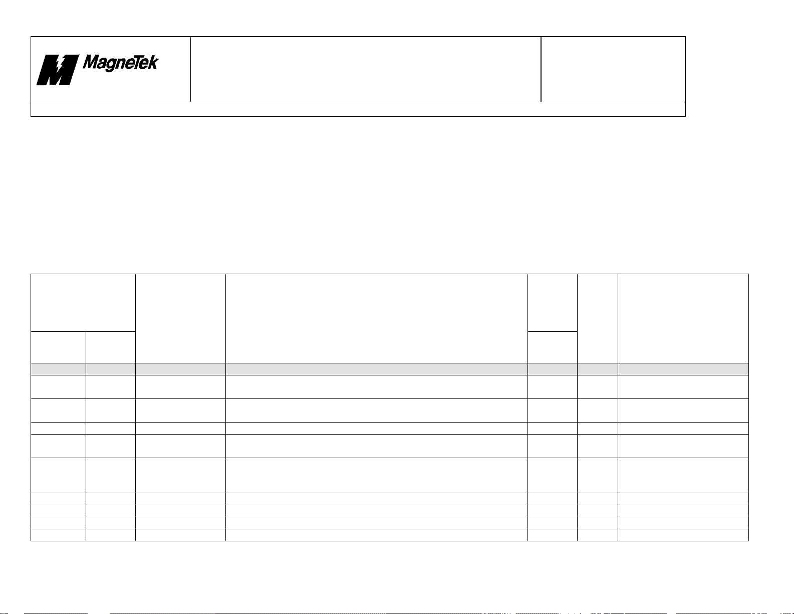
10/17/00
Smart Trac
Faults.doc
Rev. # 19 Page 59 of 64
New Berlin
Technology Center
Product Development
Design
Document
Title: Fault Declarations
7. IO Subsystem
The following section details fault numbers assigned to the Smart Trac AC1 IO Subsystem.
Notes:
• Fault legend cannot be changed in this section.
• Internal fault values do not apply here. IO Subsystem faults are not added with 10000 HEX.
• As of this printing, IO Subsystem faults cannot be displayed in the Fault Manager. Because of this, IO Subsystem faults cannot be assigned to a program input.
• TBD = To Be Determined.
• N/A = Not Applicable.
• For all faults listed in the section, the Corrective action is the same: Verify that there are no hardware problems on the PC used to create the application. Re-compile and
reload the program and reload it to the SmartTrac drive. The Smart Trac main CPU card may be faulty. If available, download a small test program to see if fault persists.
Severity
Displayed Fault No.
Fault Legend Description
Control
Node
Monitor
90000000 TBD Not a fault
90000001 TBD IO Scan Init Flt I/O Scan Manager is already initialized. Issue IO_SHUTDOWN before
90000002 TBD IO Scan Uninit I/O Scan Manager has not been initialized. Issue an IO_STARTUP
90000003 TBD IO Memory Fail Memory allocation (malloc/calloc) failed. Critical
90000004 TBD IO Load Library Unable to perform a load library on a driver DLL. DLL may not have
90000005 TBD IO DLL Addr Fail Unable to GetProcAddress on a required driver DLL function. DLL
90000006 TBD IO Thread Create Unable to create a required I/O thread during I/O startup. Critical
90000007 TBD IO Thread Delete Unable to delete a required I/O thread during I/O shutdown. Critical
90000008 TBD IO Event Create Unable to create a required event during I/O startup. Critical
90000009 TBD IO Bad Driver Driver version is incompatible with the I/O Scan Manager. Critical
The informatio n co ntained in this docum e nt is the CONFIDENTIAL property of MagneTek Inc.
File = N:\PROJECT\515\SmartTrac\DOCS\Faults.DOC Print Date: 10/17/00
Fault
Manager
Major
attempting to restart.
Major
command before proceeding.
Critical
been downloaded or may not have exported DllEntryPoint.
Critical
may not have been downloaded, ma y be an old version, or ma y not
export all required functions.
59
Assign Program
Input
N/A
N/A
N/A
N/A
N/A
N/A
N/A
N/A
N/A
Corrective Action
See above.
See above.
See above.
See above.
See above.
See above.
See above.
See above.
See above.
Page 61

10/17/00
Smart Trac
Faults.doc
Rev. # 19 Page 60 of 64
New Berlin
Technology Center
Product Development
Design
Document
Title: Fault Declarations
Severity
Displayed Fault No.
Fault Legend Description
Control
Node
Monitor
9000000A TBD IO Num Of Cards Number of cards requested in startup exceeds limit. Critical
9000000B TBD IO Unknown Req Caller requested something unsupported by the I/O Scan Manager. This
9000000C TBD IO Unknown Card Caller attempted to connect to a card that does not exist in the I/O Scan
9000000D TBD IO Bad Handle Caller attempted an I/O operation with an invalid handle. Handles are
9000000E TBD IO Queue Size An error was detected while trying to shrink the I/O request queue.
9000000F TBD IO Queue Ovrflow An I/O driver's or the I/O Scan Manager's queue overflowed. Critical
90000010 TBD IO Queue Empty An I/O driver's or the I/O Scan Manager's queue is empty. Major
90000011 TBD IO Invalid Queue An attempt was made to access a non-existent driver queue. Critical
90000012 TBD IO Image Overrun An attempt was made to write beyond the boundaries of an I/O Image.
90000013 TBD IO Access Fault A NULL pointer was passed to the I/O Scan Manager. Critical
90000014 TBD IO Driver Fail An I/O driver or one or more of its cards failed to start. Major
90000015 TBD IO Req Cancel An I/O request was cancelled. Typically this happens when one or more
90000016 TBD IO Invalid Count For multi-card commands, such as SET_SCAN_MODE, an invalid card
Fault
Manager
Critical
is a critical fault, because the I/O Scan Manager assumes the runtime
engine is confused.
Major
Manager's list of cards.
Major
created via IO_CONNECT_CARD.
Critical
Either the caller tried to shrink it to less than it's minimum size or there
were more items in the queue than the requested size. The queue is
resized during an IO_STARTUP or IO_SHUTDOWN request.
Critical
This typically means the caller is confused about the size of the image
or so meho w memory was c orru p ted.
Major
I/O requests are in the I/O Scan Manager's queue when it is executing
an IO_SHUTDOWN command. The I/O Scan Manager clears the
queue, returning a status of IO_REQUEST_CANCELLED for all
requests.
Major
count was submitted. For example, zero.
Assign Program
Input
N/A
N/A
N/A
N/A
N/A
N/A
N/A
N/A
N/A
N/A
N/A
N/A
N/A
Corrective Action
See above.
See above.
See above.
See above.
See above.
See above.
See above.
See above.
See above.
See above.
See above.
See above.
See above.
The informatio n co ntained in this docum e nt is the CONFIDENTIAL property of MagneTek Inc.
File = N:\PROJECT\515\SmartTrac\DOCS\Faults.DOC Print Date: 10/17/00
60
Page 62

10/17/00
Smart Trac
Faults.doc
Rev. # 19 Page 61 of 64
New Berlin
Technology Center
Product Development
Design
Document
Title: Fault Declarations
Severity
Displayed Fault No.
Fault Legend Description
Control
Node
Monitor
90000017 TBD IO Bad Start Seq Unknown start sequence requested. Major
90000018 TBD IO Bad Scan Mode An unknown scan mode was requested. Major
90000019 TBD IO Function Bad Function is currently unsupported, but a stub exists. Major
9000001A TBD IO Card Owned The I/O Scan Manager has already established a connection to an I/O
9000001B TBD IO Card Faulted The I/O card reported a fault. Operation not performed. Major
9000001C TBD IO Invalid Size Writes to the I/O Image and to the cards must have a length of at least
9000001D TBD IO Shutdown Mode An unknown shutdown mode was requested. Major
9000001E TBD IO Unknown State An unknown safe state. Major
9000001F TBD IO Watchdog Valu Watchdog period must be 0 (disabled) or positive number. Major
90000020 TBD IO Watchdog Flt I/O Scan Manager-to-driver watchdog expired. Major
90000021 TBD IO Unknown CTRL Unsupported I/O control for this I/O driver. Major
90000022 TBD IO Pending Asynchronous request is pending. Major
90000023 TBD IO Event Missing I/O event (not to be confused with OS event) not found. Major
90000024 TBD IO Scan Mgr Flt I/O Scan Manager is not responding to service requests. Critical
90000025 TBD IO Global Input
90000026 TBD IO Card Output
90000027 TBD IO Driver Faulted I/O Driver is faulted. Major
90000028 TBD IO Scan Mgr Flt I/O Scan Ma nager thread is faulted. Critical
90000029 TBD IO Driver Server I/O Driver Service thread is faulted. Critical
9000002A TBD IO Card Deadlock I/O card access is deadlocked. Major
9000002B TBD IO Card Offline I/O card is offline or faulted. Major
9000002C TBD IO Duplct Driver I/O driver has multiple entries. Critical
9000002D TBD IO Que Deadlock I/O queue access is deadlocked. Critical
The informatio n co ntained in this docum e nt is the CONFIDENTIAL property of MagneTek Inc.
File = N:\PROJECT\515\SmartTrac\DOCS\Faults.DOC Print Date: 10/17/00
Fault
Manager
Major
card. Only one owner is allowed.
Major
one byte. Operation not performed.
Failed to update global I/O image. Major
Fail
Failed to write global output image to card. Major
Fail
61
Assign Program
Input
N/A
N/A
N/A
N/A
N/A
N/A
N/A
N/A
N/A
N/A
N/A
N/A
N/A
N/A
N/A
N/A
N/A
N/A
N/A
N/A
N/A
N/A
N/A
Corrective Action
See above..
See above.
See above.
See above.
See above.
See above.
See above.
See above.
See above..
See above.
See above.
See above.
See above.
See above.
See above.
See above.
See above.
See above.
See above.
See above.
See above..
See above.
See above.
Page 63

10/17/00
Smart Trac
Faults.doc
Rev. # 19 Page 62 of 64
New Berlin
Technology Center
Product Development
Design
Document
Title: Fault Declarations
Severity
Displayed Fault No.
Fault Legend Description
Control
Node
Monitor
9000002E TBD IO Unload Driver Unload of I/O driver failed. The driver must first be shutdown before
9000002F TBD IO Drivr Deadloc I/O driver object access is deadlocked. Critical
90000030 TBD IO No Card Start I/O card has not started. Major
90000031 TBD IO File Open Flt Unable to EmbFopen the file. File does not exist. Major
90000032 TBD IO Driver Name Driver name in INI file does not match actual driver name. Major
90000033 TBD IO Bad Parameter Parameter in INI file is invalid. Major
90000034 TBD IO Exception Flt I/O Subsystem encountered an unhandled exception and is expecting
90000035 TBD IO Unknown IRQ An invalid IRQ number was used in an attempt to connect to an
90000036 TBD IO IRQ Reserved An attempt was made to connect to a reserved interrupt, i.e., another
90000037 TBD IO Card Cfg Flt An I/O card failed to start. The driver was unsuccessful in starting the
90000038 TBD IO Object Uninit The driver was unable to initialize a Device Object due to a problem
90000039 TBD IO Oper Timeout Asynchronous I/O operation timed out before completion. Major
9000003A TBD IO Card Cmd Flt I/O Card reported failure of command issued to it. Major
9000003B TBD IO Cmd Not Done I/O Card has a command in progress and is unable to execute/queue
9000003C TBD IO No Sync Allow I/O Card does not support synchronization. Major
9000003D TBD IO Invalid OS I/O Card does not support this Operating System. Major
9000003E TBD IO RTE Exception I/O Subsystem encountered an unhandled exception in the RTE Service
9000003F TBD IO ISR Thread EmbIsrWorkerThread()'s WaitForSingleObject returned an unexpected
Fault
Manager
Major
unloading.
Critical
caller to invoke fault handler.
Major
interrupt.
Major
driver/card has already claimed the interrupt for exclusive access.
Major
card due to H/W or configuration failure.
Major
with the INI file or insufficient system resources.
Major
another command.
Critical
Thread and is expecting caller to invoke fault handler.
Major
result.
Assign Program
Input
N/A
N/A
N/A
N/A
N/A
N/A
N/A
N/A
N/A
N/A
N/A
N/A
N/A
N/A
N/A
N/A
N/A
N/A
Corrective Action
See above.
See above.
See above.
See above.
See above.
See above.
See above.
See above.
See above.
See above.
See above.
See above.
See above..
See above.
See above.
See above.
See above.
See above.
The informatio n co ntained in this docum e nt is the CONFIDENTIAL property of MagneTek Inc.
File = N:\PROJECT\515\SmartTrac\DOCS\Faults.DOC Print Date: 10/17/00
62
Page 64

10/17/00
Smart Trac
Faults.doc
Rev. # 19 Page 63 of 64
New Berlin
Technology Center
Product Development
Design
Document
Title: Fault Declarations
Severity
Displayed Fault No.
Fault Legend Description
Control
Node
Monitor
90000040 TBD IO Bad Card Stat Bad Card status is returned from IoDrvSetScanMode(). Major
90000041 TBD IO Event Size Event Size is invalid. Major
90000042 TBD IO Event Type Event Type is invalid. Major
90000043 TBD IO Fail Generic error code. Major
Fault
Manager
Assign Program
Input
N/A
N/A
N/A
N/A
Corrective Action
See above.
See above.
See above.
See above.
The informatio n co ntained in this docum e nt is the CONFIDENTIAL property of MagneTek Inc.
File = N:\PROJECT\515\SmartTrac\DOCS\Faults.DOC Print Date: 10/17/00
63
Page 65

10/17/00
Smart Trac
Faults.doc
Rev. # 19 Page 64 of 64
New Berlin
Technology Center
Product Development
Design
Document
Title: Fault Declarations
8. Boot
The following section details faults assigned to the Smart Trac AC1 Boot, announced during power up.
Notes:
• There are no fault numbers associated with Boot code.
• Boot faults cannot be displayed in Control Node Monitor nor Fault Manager.
• Severity and Assign Program Input are listed as ‘N/A’ (Not Applicable) here. Although these faults are considered as major, the Fault Manager cannot configure nor report
them.
Assign Program
Input
N/A
N/A
N/A
N/A
Corrective Action
Smart Trac AC1 CPU card may not be connected to inverter card. Inverter
FLASH code may be incorrect. Note: press ESC key to bypass
communications with inverter card, and jump into the operating system.
Monitor is either defective or hasn’t been installed. Load new Monitor
firmware into Smart Trac AC1 CPU card, with JTAG programmer.
Possibility boot code does not exist in Smart Trac AC1 CPU card. Check
integrity of cable between digital operator and Smart Trac.
Operating system on Smart Trac AC1 CPU card may have stopped
running. Monitor and/or Kernel firmware may be defective or missing.
Application program may be invalid. Check integrity of cable between
digital operator and Smart Trac AC1.
Displayed Fault
No.
Fault Legend Description
Control
Node
Monitor
Fault
Manager
N/A N/A No Drive
Comms
N/A N/A No Monitor or
OS
N/A N/A CPF00
COMERR(OP&INV)
N/A N/A CPF01
COMERR(OP&INV)
Communica t ions betwee n Smart
Trac AC1 CPU card and inverter
card have not been established.
Boot cannot detect valid Monitor
firmware in the Smart Trac AC1
CPU card.
Communica t ions betwee n the
Digital Operator and Smart Trac
AC1 was not established within 5
seconds after power was applied.
Communica t ions betwee n the
Digital Operator and Smart Trac
AC1 have not taken place for a
least 2 seconds (after
communications had already been
established).
Severity
N/A
N/A
N/A
N/A
The informatio n co ntained in this docum e nt is the CONFIDENTIAL property of MagneTek Inc.
File = N:\PROJECT\515\SmartTrac\DOCS\Faults.DOC Print Date: 10/17/00
64
Page 66

SMART TRAC AC1 Fault Tables
Data subject to change without notice. Smart Trac is a trademark of MagneTek, Inc. MicroTrac is a registered trademark of MagneTek, Inc. Microsoft, Windows and Windows NT are registered
trademarks of Microsoft Corporation
MagneTek
Drives and Systems
16555 West Ryerson Road
New Berlin, WI 53151
(800) 541-0939, (262) 782-0200, FAX (414) 782-3418
TM 3643-0000 © 1999-2000 MagneTek, Inc. 1/31/2000
 Loading...