

Page 1
Technical Manual
™
™
S
M
A
R
S
M
A
R
T
T
T
T
R
R
A
A
C
C
Ett
E
h
h
err
e
n
n
ett
e
C
C
arr
a
d
d
Page 2

Page 3

SMART TRAC Ethernet Card
Contents
Safety and Warranty Information 3
Warnings, Cautions and Notes.....................................................................................................................3
General Safety Precautions - Warnings ......................................................................................................4
Important Warranty Information................................................................................................................4
Smart Trac Ethernet Card 5
General Capabilities......................................................................................................................................5
Smart Trac AC1 on an Ethernet Network .................................................................................................5
Specifications .................................................................................................................................................5
System Requirements....................................................................................................................................6
Quick Start.....................................................................................................................................................6
Ethernet Basics 7
Introduction...................................................................................................................................................7
Ethernet and the OSI Model..............................................................................................................8
TCP/IP and the OSI Model ...............................................................................................................8
Ethernet Network Topology.........................................................................................................................8
Bus ....................................................................................................................................................8
Star....................................................................................................................................................9
Cabling and Cable Lengths ........................................................................................................................10
Ethernet Hub or Crossover Cable?............................................................................................................11
Installing the Smart Trac Ethernet Card 13
Unpacking ....................................................................................................................................................13
Electrostatic Discharge (ESD) Procedures......................................................................................13
Unpacking Procedure......................................................................................................................13
Installing the Smart Trac Ethernet Card..................................................................................................14
Connecting the Smart Trac Ethernet Card to an Ethernet Network ....................................................15
Configuring the Smart Trac Ethernet Card 17
The Ethernet Card's Jumperless Settings.................................................................................................17
Interrupt...........................................................................................................................................17
Base I/O Address.............................................................................................................................17
Ethernet Network Configuration...............................................................................................................17
Addresses and subnet mask.............................................................................................................17
Configuration for PC-Based Operation...........................................................................................18
Configuration for an Enterprise-wide LAN ....................................................................................19
Verifying Your TCP/IP Configuration............................................................................................20
Testing Card Installation 23
Technical Manual Smart Trac Ethernet Card Contents •• i
Page 4

SMART TRAC Ethernet Card
Testing the Network....................................................................................................................................23
On-board Indicator Lights .........................................................................................................................23
Troubleshooting Your Smart Trac Ethernet Card 25
Status and Error Messages.........................................................................................................................25
Troubleshooting Ethernet Network Problems..........................................................................................25
Appendix A – Technical Support 29
Technical Support .......................................................................................................................................29
Problem Report ...........................................................................................................................................31
References ....................................................................................................................................................32
Appendix B – Card Layout 33
Smart Trac Ethernet Card Layout............................................................................................................33
Appendix C – Replaceable Parts 37
Replaceable Parts Listing ...........................................................................................................................37
Appendix D – Removing the Smart Trac Card Stack 39
General Procedures.....................................................................................................................................39
Glossary of Terms 43
Index 45
ii •• Contents Technical Manual Smart Trac Ethernet Card
Page 5
SMART TRAC Ethernet Card
Safety and Warranty Information
Warnings, Cautions and Notes
WARNING
A statement of conditions which MUST BE OBSERVED to
prevent personal injury or death.
WARNING - ESD
A statement of conditions which must be observed to prevent
damage to components due to ESD (ElectroStatic Discharge) and
to prevent personal injury or death.
CAUTION
A statement of conditions which must be observed to prevent
undesired equipment faults, Smart Trac AC1 system degradation
and damage to equipment.
IMPORTANT
A statement of conditions which should be observed during Smart Trac AC
DeviceNet setup or operation to ensure dependable service.
NOTE: Notes indicate information that is in addition to a discussion of the topic
in adjoining text. Alternatively, it may limit or restrict the paragraph(s) that
follow(s) to specific models or conditions.
TIP - Tips indicate information that should make a procedure easier or more
efficient.
Technical Manual Smart Trac Ethernet Card Safety and Warranty Information •• 3
Page 6
SMART TRAC Ethernet Card
General Safety Precautions Warnings
Important safety information follows. Please read and understand all
precautions listed below before proceeding with the specification, installation,
set-up or operation of your Smart Trac AC1. Failure to follow any of the
following precautions may result in personal injury or death, or damage to the
equipment.
WARNING - ESD
The Control Printed Circuit Board (PCB) employs CMOS
Integrated Circuits that are easily damaged by static electricity.
Use proper ElectroStatic Discharge (ESD) procedures when
handling the Control PCB. See Smart Trac AC1 Technical Manual
for details. Failure to comply may result in damage to equipment
and/or personal injury.
Important Warranty Information.
Do not modify your Smart Trac AC1, its components, or any of the procedures
contained in the technical documentation supplied by MagneTek. Any
modification of this product by the user is not the responsibility of MagneTek
and will void the warranty.
4 •• Contents Technical Manual Smart Trac Ethernet Card
Page 7

SMART TRAC Ethernet Card
Smart Trac Ethernet Card
General Capabilities
With the Smart Trac Ethernet Card in your Smart Trac AC1, your system is
fully compatible with the IEEE 802.3 Ethernet standard, the most widely used
local area network (LAN) standard. The card provides a fast, reliable, PC-based
interface to the Smart Trac AC1. As an alternative to a serial RS-232
connection, a Smart Trac Ethernet card may be used for high speed (10 Mbps)
monitoring, program uploading and downloading, and running diagnostics.
Smart Trac AC1 on an Ethernet
Network
The card also allows quick, easy and inexpensive networking of a Smart Trac
AC1 with PCs, other Smart Trac AC1s, and other industrial devices. Using the
TCP/IP protocol means that your Smart Trac AC1 system may operate as part of
a Local Area Network (LAN) or a Wide Area Network (WAN).
Specifications
• Hardware and software compatible with Novell NE2000 ISA bus
Ethernet adapter and PC/104 standard
• Complies with the 802.3 CSMA/CD Ethernet standard for 10 Mbps
data transfer.
• Built-in 10Base-T transceiver for unsheilded, twisted pair cabling up to
100 meters in length. Optional 10Base2 transceiver module. AUI
connector for external 10Base5 transceiver
• Single +5V power supply at 400 milliamp maximum without external
transceiver).
• Two diagnostic LEDs
• On-board 32K memory provides a high-performance, multi-package
buffer.
• Operating Temperature: 0° C to 70° C
• Operating Humidity: 10% to 90%
Technical Manual Smart Trac Ethernet Card Smart Trac Ethernet Card •• 5
Page 8

SMART TRAC Ethernet Card
System Requirements
• Smart Trac AC1 Drive
• Smart Trac CPU card
• Smart Trac PS card
• Smart Trac Ethernet Network Option Kit
• Microsoft Windows NT 4.0 or newer version
• Smart Trac Workstation Lite™ software
• Ethernet 10Base-T twisted pair crossover cable OR two Ethernet
10Base-T twisted pair straight cables and an Ethernet hub
Quick Start
Your Smart Trac Ethernet card is ready to install. Its base I/O address is set at
0x320 hexadecimal with an IRQ of 5.
1. Power OFF your Smart Trac AC1, lock out and tag "Out of Service."
2. Remove any existing PC/104 option cards from your Smart Trac AC1.
3. Install the Smart Trac Ethernet card on top of the Smart Trac PS Card.
4. Install any Smart Trac cards previously removed.
5. Connect the Ethernet network crossover cable between a PC and your
Smart Trac AC1. Optionally, you may install one Ethernet straight
cable between PC and hub with another straight cable between hub and
Smart Trac AC1.
6. Power up your PC, hub and Smart Trac AC1.
7. Test your card installation.
6 •• Contents Technical Manual Smart Trac Ethernet Card
Page 9
Ethernet Basics
Introduction
Ethernet is a low cost, widely used LAN access method. Originally developed
by Intel, Digital (now Compaq), and Xerox, it is an open network standard
(IEEE 802.3).
SMART TRAC Ethernet Card
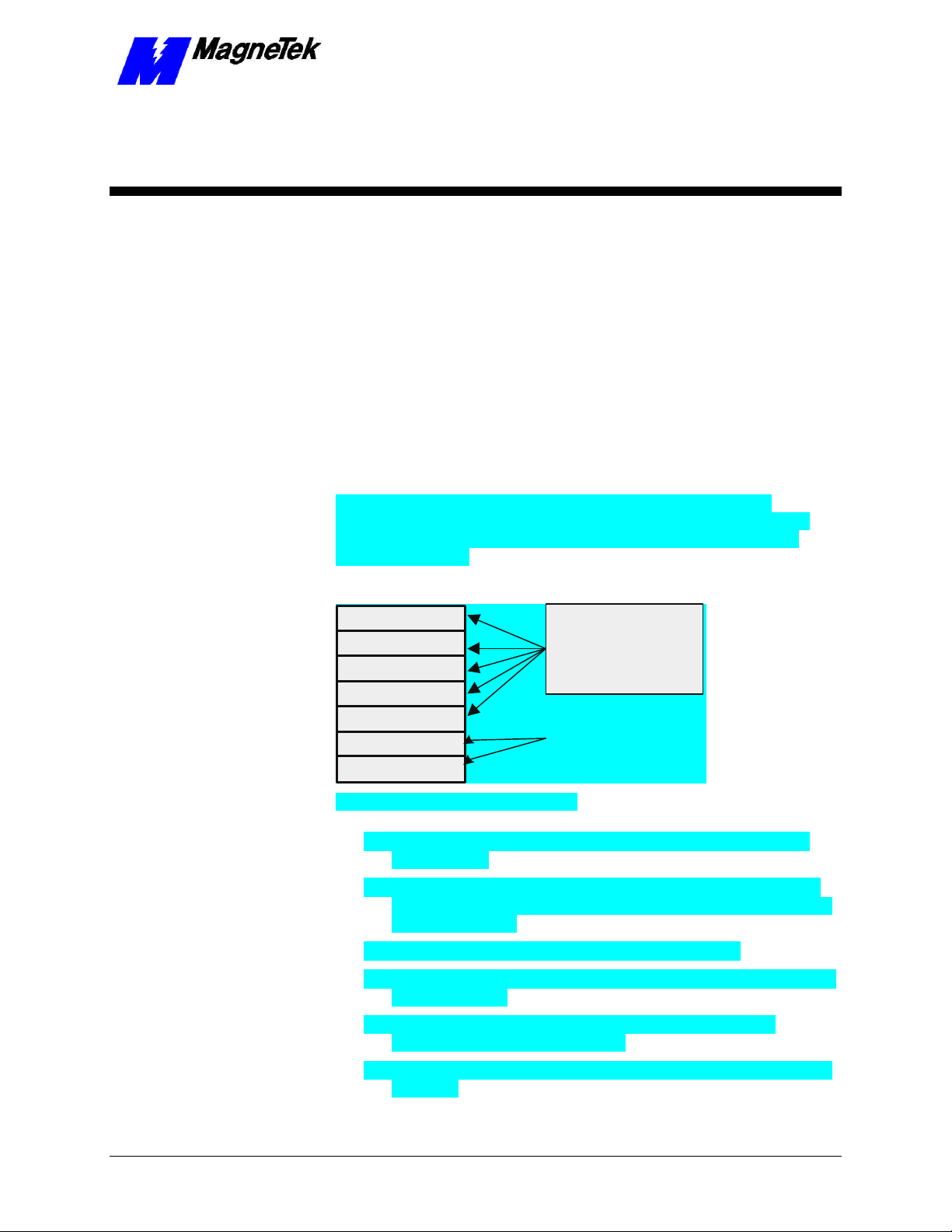
The Open Systems Interconnect (OSI), established in 1984 by the ISO
(International Standards Organization), divides network functions into seven
layers: Physical, Data Link, Network, Transport, Session, Presentation and
Application Protocol.
Application
Presentation
Session
Transport
Network
Data Link
Physical
Figure 1. Ethernet and the OSI Model.
• The Physical Layer transforms data into bits that are sent across the
physical media.
• The Data Link layer determines access to the network media in terms
of frames. Its Media Access Control (MAC) sublayer is responsible for
physical addressing.
• The Network Layer routes data through a large network.
TCP/IP protocol on
Ethernet provides
all seven layers of
the OSI model.
Ethernet provides
these layers of the
OSI (Open Systems
Interconnect) model.
• The Transport Layer provides end-to-end, reliable connections, often in
terms of segments.
• The Session Layer allows users to establish connections using
intelligently chosen names in packets.
• The Presentation Layer negotiates data exchange formats, also in terms
of packets.
Technical Manual Smart Trac Ethernet Card Ethernet Basics •• 7
Page 10

SMART TRAC Ethernet Card
• Finally, the Application Layer provides the interface between the user's
application and the network through messages.
Data is said to move from layer to layer within the seven layers of the OSI
model.
Ethernet and the OSI
Model
TCP/IP and the OSI
Model
Ethernet supports the physical and data link layers. With TCP/IP as its protocol,
it supports all seven layers of the OSI model.
Several types of Ethernet cables support the physical layer. See "Cabling and
Cable Lengths" for details.
Using Carrier Sense Multiple Access/Collision Detection (CSMA/CD), Ethernet
supports the data link layer. CSMA/CD checks the media for other devices
before transmitting, managing data collisions and reducing the number of data
collisions.
Ethernet uses Transmission Control Protocol/Internet Protocol (TCP/IP) to
provide layers of the OSI model. Although developed under an older four-layer
network model developed by the U.S. Department of Defense (DoD), we can
loosely fit the four layers of the DoD model to the seven of the OSI model.
Physical and Data Link layers are supported through the Network Access layer
of the DoD model. TCP/IP can run on many types of network connection,
including ethernet. Ethernet supports both the Physical and Data Link layers of
the OSI model.
The Network layer of the OSI model corresponds with the Internet layer of the
DoD model. Internet Protocol provides this layer, moving data to other devices
on the network.
The Transport layer corresponds to the Host-to-Host layer of the DoD model.
Almost all devices on a TCP/IP network are considered hosts, and this layer
communicates data peer-to-peer (or host-to-host).
Bus
Star
The Session, Presentation and Application layers of the OSI model correspond
to the Process/Application layer of the DoD model, providing network services.
Ethernet Network Topology
Devices on an Ethernet network are arranged in either a bus or star topology.
In a bus topology, all devices on the network connect to one trunk cable. This
makes it easy to install and configure, and inexpensive. Ethernet in a bus
topology requires no special equipment to amplify or regenerate the signal. Any
device wanting to send information must first determine if the bus is being used
by any other device. If no other device is attempting to transmit, the device
sends the data. Bus networks generally require that proper terminations are made
at each end of the trunk. If the trunk cable fails, all devices are affected.
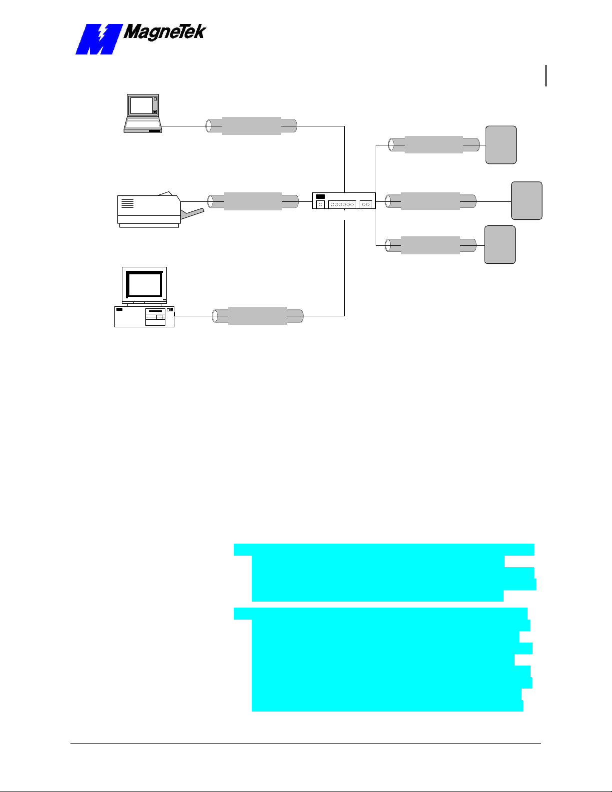
In a star topology, a separate cable connects each device with a central device,
typically a hub. Unlike the bus topology, if a cable fails it affects only the one
device connected to the failed cable. Star networks are easily expanded, easier to
troubleshoot and support many types of cables. To connect more than two
devices together in a star topology requires the use of either a passive or active
hub. Passive hubs do not regenerate the signal. Use of active hubs extends
network length by regenerating the signal and sending it across the network.
A typical PC-based network for operation of Smart Trac AC1s is depicted in
Figure 2.
8 •• Contents Technical Manual Smart Trac Ethernet Card
Page 11
SMART TRAC Ethernet Card
Cat-5 Twisted Pair
Laptop computer
Ethernet Cable
Cat-5 Twisted Pair
Ethernet Cable
SMART
TRAC
AC 1
Laser printer
IBM Compatible
Cat-5 Twisted Pair
Ethernet Cable
Cat-5 Twisted Pair
Ethernet Cable
Cat-5 Twisted Pair
Ethernet Cable
Hub
Cat-5 Twisted Pair
Ethernet Cable
SMART
TRAC
AC 1
SMART
TRAC
AC 1
Figure 2. A typical local area network used for PC-based operation of Smart
Trac AC1s.
Cabling and Cable Lengths
Ethernet supports several types of cables, each intended for different purposes:
• 10Base-T (Twisted-pair Ethernet) – The most widely used Ethernet
cabling, it supports network speeds of 100Mbps. Uses 22- or 26-AWG
UTP cabling to transmit baseband signals on maximum 100-meter
segments. RJ-45 jacks connect separate cables between device and hub.
Each device must be at least 2 feet apart and no more than 328 feet
from the hub. Bridges or routers may be used to accommodate a larger
network. There is no limit on network length. It permits a maximum of
1,024 segments and 1,024 nodes. See IEEE standard 802.3i.
• 10Base-2 (Thin Ethernet) – Supports network speeds of 10Mbps. Uses
RG-58 coaxial cable to transmit baseband signals on 200-meter
segments. Total network length can be 925 meters. Transceivers reside
on the NIC, simplifying connections. The cable, thinner than 10Base-5,
is more flexible for easier handling. See IEEE standard 802.3a.
• 10Base-5 (Thick Ethernet) – Now rarely used, this cable was popular
for desktop connections until the introduction of 10BaseT. It supports
networks speeds of up to 10Mbps and uses RG-8 or RG-11 coaxial
cable to transmit baseband signals in 500-meter (1,640 feet) segments.
Total network length can be 2,500 meters with up to 300 nodes. It
requires the use of transceivers located at least 8 feet apart and tapped
into the cable. A 15-pin AUI, or DIX (Digital, Intel, Xerox) connector
is used between the network cable and the AUI port on the Ethernet
NIC (Network Interface Card). See IEEE standard 802.3 for details.
Technical Manual Smart Trac Ethernet Card Ethernet Basics •• 9
Page 12

SMART TRAC Ethernet Card
Ethernet Hub or Crossover Cable?
An Ethernet hub is required if connecting more than two devices (more than one
Smart Trac AC1 and one computer). If only connecting a single Smart Trac with
a single computer, you need only a special "crossover" or "uplink" Ethernet
cable.
You may construct a crossover cable using UTP Category 5 cable, two twisted
pair connectors (WE8W 8 pin modular) and the pinouts indicated in Figure 3.
The Tx and Rx pairs are swapped (orange and green wires, 1, 2 and 3, 6). You
can locate Pin 1 of a twisted pair connector (WE8W 8-pin modular) by holding
the connector with the keytab down and the contacts up. Looking from the back
of the connector where the wire will be inserted, pin 1 is on the left.
Pin 1 Wht/Org T2
2 Org/Wht R2
3 Wht/Grn T3
4 Blu/Wht R1
5 Wht/Blu T1
6
Grn/Wht R3
7 Wht/Brn T4
8 Brn/Wht R4
Figure 3. Ethernet crossover cable pinout.
Pin 1 Wht/Green T3
2 Grn/Wht R3
3 Wht/Org T2
4 Blu/Wht R1
5 Wht/Blu T1
6 Org/Wht R2
7 Wht/Brn T4
8 Brn/Wht R4
10 •• Contents Technical Manual Smart Trac Ethernet Card
Page 13
SMART TRAC Ethernet Card
Installing the Smart Trac
Ethernet Card
Unpacking
Electrostatic
Discharge (ESD)
Procedures
Unpacking Procedure
WARNING WARNING -- ESD ESD
Keep electronic circuit boards in Electrostatic Discharge (ESD)
protective bags when not being handled. Use proper ESD
procedures (including an ESD wrist strap) when handling circuit
boards. Failure to comply may result in damage to equipment.
When working with an electrostatic discharge (ESD) sensitive device, you
should be grounded at all times. The easiest and most common way to provide
this ground is to use an approved ESD wrist strap. The strap is secured to your
wrist with a wire attached to the strap and clipped or taped to the chassis of the
unit being worked on. Any static is dissipated through the wire to ground,
greatly reducing the possibility of damage to the device.
It is a good idea to touch the chassis with your finger before handling any
electrostatic sensitive device. Any static electricity will be discharged to chassis
ground and will not be transferred to the device.
Always store devices (cards, other electronic components) in ESD protective
bags when not being handled.
Remove the protective shipping and packing material from the card. Ensure
contact wedges and other shipping devices have been removed.
Installing the Smart Trac Ethernet
Card
The Smart Trac Ethernet Card must be positioned above the Smart Trac PS Card
in the Smart Trac card stack.
NOTE: If replacing or adding a Smart Trac Ethernet card to an existing Smart
Trac card stack, see "Appendix D – Removing the Smart Trac Card Stack"
before continuing.
Technical Manual Smart Trac Ethernet Card Installing the Smart Trac Ethernet Card •• 11
Page 14

SMART TRAC Ethernet Card
Optional
Standoffs (4
places on top of
each card)
PC/104
Card
Optional
PC/104
Card
Smart Trac
Ethernet
Card
4CN
Smart Trac
PS Card
Connector
Smart Trac
PG Card
2CN
Connector
Smart Trac
CPU Card
Inverter Control
Card
Adapter
Ring
Main Chassis
Figure 4. Smart Trac Ethernet Card Stack Position
1. To install the Ethernet card, orient the pins on the card at ZJ1 and ZJ2
with the female pin connector on the card below it (the PS Card).
Gently but firmly push the Smart Trac Ethernet card onto the card
below it. Make sure connecting pins are in alignment before pushing
the two boards tightly together. Secure the card using four (4) metal
standoffs.
2. Replace all other cards, securing each with four (4) metal standoffs and
the reverse of steps in "Appendix D – Removing the Smart Trac Card
Stack".
12 •• Contents Technical Manual Smart Trac Ethernet Card
Page 15

SMART TRAC Ethernet Card
Connecting the Smart Trac Ethernet
Card to an Ethernet Network
1. Take one of the following three actions:
• Using twisted pair cable for 10Base-T, plug the RJ-45 UTP cable
connector into the receptacle at the RJ-45 connector on the card.
• If using an AUI Ethernet connector for 10Base5, connect the Thick
Ethernet RG-8 or RG-11 cable to the 16-pin AUI connector.
• If using the optional 10Base-2 daughterboard, use either the BNC
connector for a T-connection to 10Base-2 thin cable ethernet or the
16-pin connection to the AUI port.
2. Route cable so that it is not routed along with A/C wires. Ethernet cable
should not be bundled. Before applying power to the system, inspect
the planned cable route to ensure it is not near A/C wires .
Technical Manual Smart Trac Ethernet Card Installing the Smart Trac Ethernet Card •• 13
Page 16

Page 17

SMART TRAC Ethernet Card
Configuring the Smart Trac
Ethernet Card
The Ethernet Card's Jumperless
Settings
Interrupt
Base I/O Address
Addresses and
subnet mask
The Smart Trac Ethernet Card is preconfigured and jumperless.
The interrupt is factory-set to "5."
Using interrupt 5 assures you that there will be no conflicts with other basic
Smart Trac components if all are set according to their default values.
The Base I/O Address is set to 0x320. You must maintain unique addresses and
interrupts for all cards in the Smart Trac card stack.
Ethernet Network Configuration
Depending on whether you are networking for PC-based operation on a small
LAN or an enterprise-wide LAN, you may need the assistance of your LAN
Administrator to specify unique TCP/IP address, a subnet mask, and gateway
addresses.
All Ethernet cards use a unique TCP/IP address. Every device (Smart Trac AC1,
printer, computer, etc) connected to a TCP/IP network requires at least one IP
address, unique within that network. This is true whether the device is part of a
control network or not.
A TCP/IP address (i.e. "207.21.32.12") identifies the unique network ID and
host ID of a computer or host using 32-bit numbers. Each component number of
the TCP/IP address, separated by a decimal point, is referred to as an "octet".
This is because it can be represented by an eight-digit binary number.
For discussion of subnet masks and gateway addresses, see "TCP/IP Subnet
Masks" and "The Gateway Address." However, you may not need to concern
yourself with exactly what they are, viewing them only as values to be entered
during configuration.
For typical applications, you may determine the subnet mask and gateway
address as follows:
Technical Manual Smart Trac Ethernet Card Configuring the Smart Trac Ethernet Card •• 15
Page 18

SMART TRAC Ethernet Card
1. At the PC to which the Smart Trac AC1 is connected, select Start,
Settings, Control Panel. The Control Panel dialog box appears,
displaying the control icons.
2. Click the Network icon. The Network dialog box appears.
3. Click the Protocols tab.
4. In Network Protocols, select TCP/IP Protocol.
5. Click Properties, then read and record the subnet mask and gateway
address of your computer. These same values will be entered into your
Smart Trac AC1s, the desktop PC running Smart Trac Workstation
software and any other devices on your LAN.
NOTE: For most applications, you may set the subnet mask and gateway
address as described. The information in the balance of this chapter supplies
details needed only in unusual situations. Further details are provided in the
Application Notes entitled "TCP/IP and Ethernet Addressing."
Configuration for PCBased Operation
Entering addresses and
subnet mask
You configure each Smart Trac TCP/IP address on your network using the
digital operator. You configure the TCP/IP address, on a PC running Smart Trac
Workstation, in Windows NT.
To enter the TCP/IP address, Subnet Mask, and Gateway Address into the
Digital Operator:
1. Press MENU on the digital operator within 2 seconds of bootup. The
message "TCP/IP Config" screen should appear.
2. Press DATA/ENTER. You are prompted with the message "IP
Address" and below it 0.0.0.0. or another IP address.
3. Press DATA/ENTER. The first digit of the first octet will flash,
indicating it is ready to accept new data. Enter the values of each octet,
in succession, pressing the right arrow key (>RESET) to move one
octet to the right if all three digits of an octet are not required entries.
4. Once all octets are entered, press DATA/ENTER to accept the new IP
Address.
5. Press the UP arrow key to the message "Subnet Mask". Enter it as you
did the IP Address in step 3.
6. In a similar manner, enter the desired Gateway Address and DNS
Server Address, should they be required.
NOTE: For most networks, the default of no gateway address and no DNS
Server address should be accepted.
7. Press MENU when completed.
Configuration for an
Enterprise-wide LAN
16 •• Contents Technical Manual Smart Trac Ethernet Card
Smart Trac AC1s may be connected, in certain situations, to an enterprise-wide
LAN. In such cases, your LAN Administrator will need to be involved to supply
certain required addresses.
While you may be able to determine the TCP/IP address as described in
"Configuration for PC-Based Operation", you may require the more detailed
information below:
Page 19

Obtaining TCP/IP
addresses
SMART TRAC Ethernet Card
The easiest way to obtain a TCP/IP address for your Smart Trac AC1 host or
computer is to request one from your LAN Administrator. This is especially
true if the device will be on a enterprise-wide LAN.
NOTE: If your internal network is to be used on a self-contained network and
not connecting directly to the public internet or a larger enterprise-wide LAN,
you may use any valid TCP/IP address except for certain reserved addresses
(0.0.0.0, 127.0.0.1, 224.0.0.0 and 255.255.255.255). Most industrial devices fall
into this category.
If on a private network (intranet) you may use any valid Class A, B, or C
address, described below. Most other LANs fall into one of these address classes
and are assigned by the corporation's LAN Administrator.
Any device that connects directly to the internet (not through a "proxy" server)
must be assigned a network ID from the Internet Network Information Center
(InterNIC at www.internic.com). Smart Trac AC1s do not fall into this category.
TCP/IP Address
Classes
TCP/IP Subnet Masks
TCP/IP addresses are grouped into five classes, from Class A through Class E.
The first octet of the IP address specifies its classification.
• Class A – First octet is between 1 and 126 (0 is not allowed, 127 is
reserved as "loopback" address). Organizations with a very large
number of hosts (networked devices) require a Class A address.
• Class B – First octet is between 128 and 191. Large organizations with
as many as 65, 534 networked devices (workstations, printers, routers,
etc) require at least a Class B address.
• Class C – First octet is between 192 and 223. A network with less than
255 networked devices may be assigned a Class C address.
• Class D – First octet is between 224 and 239. These addresses are for
multicast groups, such as RealAudio and Microsoft NetShow.
• Class E – First octet is between 240 and 247. These addresses are
reserved for experimental purposes.
A Subnet Mask defines the split between network and host (device) parts of the
TCP/IP address. It identifies the network octets of the IP address with the
number "255" or "252" and the host octets with the number "0". This defines the
maximum number of different devices (hosts) allowed on the network. A subnet
mask of 255.255.255.0, then, identifies the first three octets of the IP address as
network parts and the last as a single host part. The use of "252" provides one or
bits of additional resolution for hosts.
Example: The address 200.20.16.5 with a subnet mask of 255.255.0.0 identifies
a network with (255*255)-2 hosts, or 65,534 hosts (two is subtracted to allow
for reserved numbers) on the network identified as "200.20".
Fortunately, Microsoft's Windows NT assigns a default subnet mask to an IP
address. It can be changed if necessary. The defaults result in the following
maximum number of networks and hosts allowed per TCP/IP address:
• Class A – 126 networks, 16,777,214 hosts (default subnet
mask=255.0.0.0).
• Class B – 16,384 networks, 65,534 hosts (default subnet
mask=255.255.0.0)
Technical Manual Smart Trac Ethernet Card Configuring the Smart Trac Ethernet Card •• 17
Page 20
SMART TRAC Ethernet Card
• Class C – 2,097,152 networks, 254 hosts (default subnet
mask=255.255.255.0)
The Gateway Address
The DNS Server
Address
Verifying Your TCP/IP
Configuration
The Gateway Address provides the IP address to which packets of data should
be sent to route them to their final destination, if on a large enterprise-wide LAN
or the internet. While the Smart Trac AC1 allows you to change the gateway
address to any required, the default of no address will work in nearly all
situations. In enterprise-wide LANs the default may not be acceptable. Contact
your LAN Administrator to determine the proper gateway address.
The DNS Server is unavailable for changes. This accepts the default of no
address. Selecting DNS Server will cause a "Not Available" message to be
displayed on the digital operator.
Refer to your computer's Operating System documentation when installing
TCP/IP services and protocol.
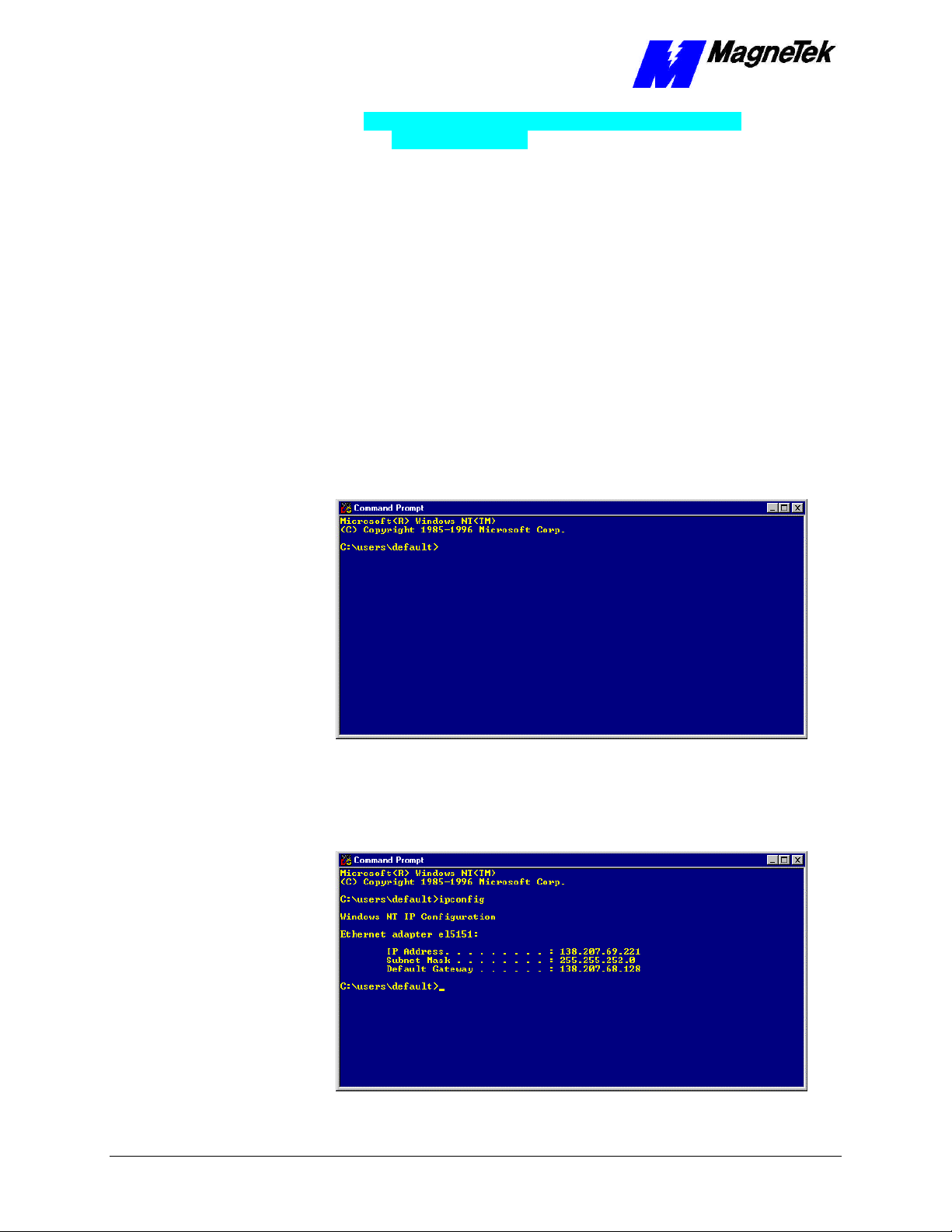
You typically verify your TCP/IP configuration with two simple commands:
IPCONFIG and PING:
1. Click START, PROGRAMS, COMMAND PROMPT. A DOS
window appears with the cursor at the default directory.
Figure 5. The Command Prompt from Windows NT
2. Type IPCONFIG. A listing should appear of the IP Address, subnet
mask, and default gateway for all network adapters to which TCP/IP is
bound on your computer.
Figure 6. IPCONFIG results
18 •• Contents Technical Manual Smart Trac Ethernet Card
Page 21
SMART TRAC Ethernet Card
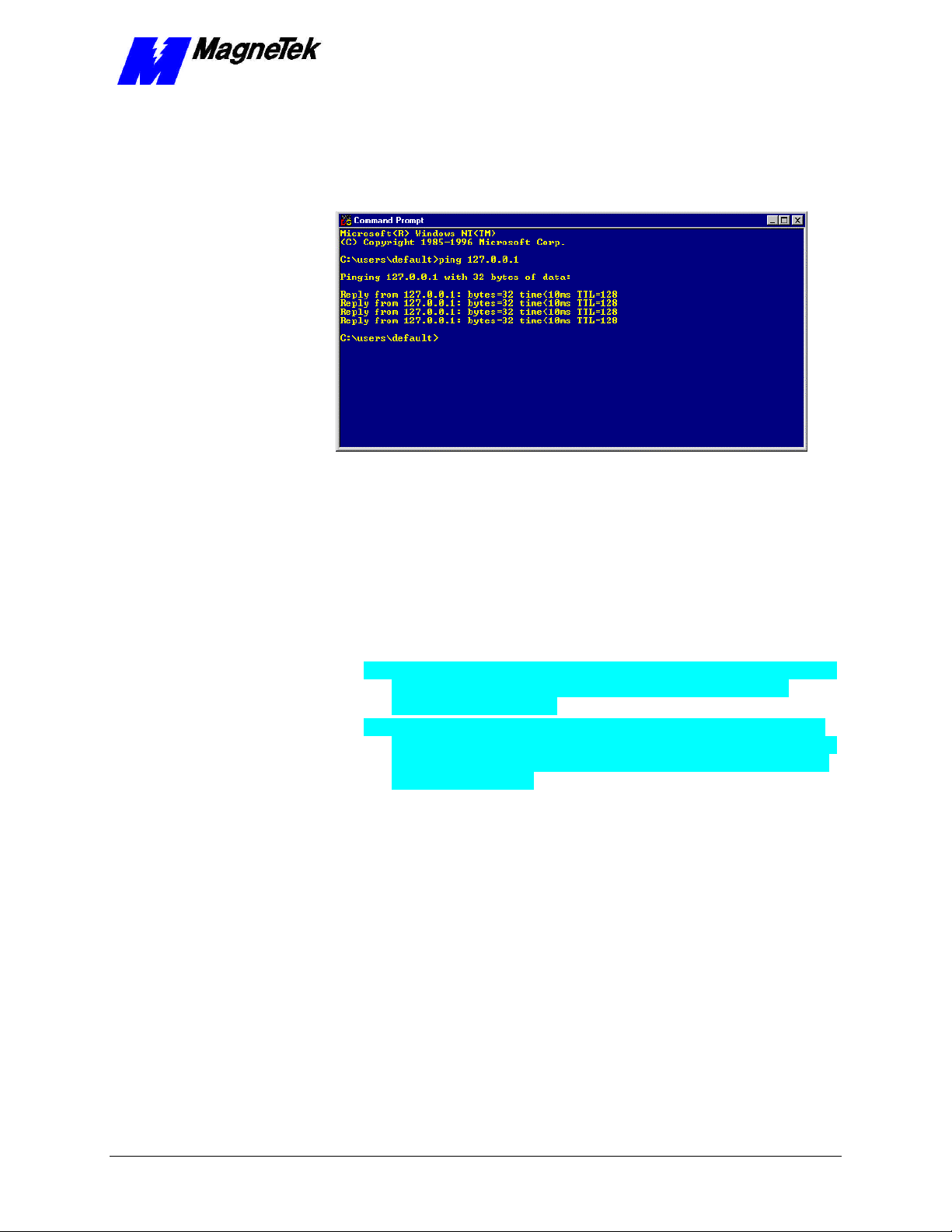
3. Type PING 127.0.0.1. The PING utility, included in Windows NT,
tests for proper TCP/IP configuration on your system with the special
"loopback" address. You should get the results shown in the following
screen. If not, the TCP/IP configuration is not correct and must be fixed
before proceeding.
Figure 7. A successful PING of the computer you are using
4. Type PING [Your IP Address]. For example, type "PING
200.20.16.5" (substitute your computer's IP Address). Results similar to
those in step 2 confirms that the IP address on your computer is
configured correctly. You will also find out if duplicate addresses exist
on your network.
5. Type PING [Address of another networked computer]. You
should get results similar to those in step 2. This confirms the IP
address of the chosen computer. You may test all other networked
computers in the same way.
6. Type PING [Address of the default network gateway]. This step
is necessary only if your system uses a gateway, to confirm your
connection to the gateway.
7. Type PING [Address of computer on other side of gateway].
This step confirms that you can connect to remote computing resources.
Again, it is only needed if your system uses a gateway and you need to
access remote systems.
Technical Manual Smart Trac Ethernet Card Configuring the Smart Trac Ethernet Card •• 19
Page 22

Page 23
SMART TRAC Ethernet Card
Testing Card Installation
Testing the Network
Once installed, check the on-board indicator Light Emitting Diodes (LEDs).
Normally:
• red LED2 should be flashing, indicating network traffic from the card.
• green LED3 should be steady ON, indicating receive activity on the
network and that your Smart Trac AC1 is an active participant in
network activities.
On-board Indicator Lights
Two LEDs on the Smart Trac Ethernet Card indicate network activity and status
information. For location, see "Appendix B – Card Layout."
Table 1. Interpretation of the LEDs.
On-board LED Functions
LED Function
LED2 (Red) Network traffic present if flashing
LED3 (Green) Ethernet card status OK if ON, not OK if OFF
Technical Manual Smart Trac Ethernet Card Testing Card Installation •• 21
Page 24

SMART TRAC Ethernet Card
THIS PAGE INTENTIONALLY LEFT BLANK
22 •• Contents Technical Manual Smart Trac Ethernet Card
Page 25

SMART TRAC Ethernet Card
Troubleshooting Your Smart
Trac Ethernet Card
Status and Error Messages
When installed, the Smart Trac Ethernet driver automatically creates a set of
global
These global variables may be assigned symbol names and used in function
blocks, application programs and/or the fault manager. If read by the fault
manager, they may be programmed to annunciate and/or to be displayed on the
Digital Operator as they occur.
Troubleshooting Ethernet Network
Problems
Use the following general guidelines to troubleshoot your Ethernet network:
1. Disconnect parts of the network and watch where the fault goes.
Disconnecting part of the network frequently solves the problem.
2. If the network was previously operating, determine what has changed.
3. Record symptoms in detail. Keep good notes about your network and
its problems to properly define the problem.
• Look for patterns in the symptoms. Do intermittent problems occur
when other un-related equipment is in use?
• Do some nodes communicate correctly? What is the difference
between the functioning nodes and the others?
Technical Manual Smart Trac Ethernet Card Troubleshooting Your Smart Trac Ethernet Card •• 23
Page 26

SMART TRAC Ethernet Card
Table 2. Hardware Configuration Troubleshooting.
Troubleshooting Hardware Configuration
Probable
Symptom
Cause Corrective Action
Devices will
not
communicate
Cable break,
short or
faulty cable
connector
Newly
installed
Ethernet
Card not
configured
properly
Corrupt
Ethernet
card driver
Check cable continuity for break or short.
Inspect connector for damage, broken
pins, or wires that have pulled loose.
Repair or replace as necessary.
Check jumper settings of other cards in
the Smart card stack to eliminate any
conflicting IRQ, I/O Base Address,
modes, etc. Correct as required.
Check LED3 (link activity). It should be
ON, indicating a good connection with
the hub (used if more than two devices
on the network) or other device(s). If not
ON, check for a loose or damaged
connection at hub. Check hub for
damage.
Check LED2 (transmit activity). It should
be ON intermittently, indicating that the
card is transmitting data.
Reinstall driver.
Check configuration of Ethernet card and
driver.
Check IP address, subnet mask, and
default gateway. Make changes as
required.
Improper
network
protocol
If network response slows down, check
for a improper configuration in Windows
NT.
selected
Power loss,
surge or
Install an Uninterruptible Power Supply
(UPS).
large
fluctuations
24 •• Contents Technical Manual Smart Trac Ethernet Card
Page 27

SMART TRAC Ethernet Card
Appendix A – Technical Support
Technical Support
Should you need technical assistance with installation or troubleshooting of your
Smart Trac AC1, you can phone our Help Desk at either (800)-541-0939 or
(262)-782-0200. Alternatively, you may copy the Problem Report form, found
on the next page, and fax it to us at (262)-782-3418.
Technical Manual Smart Trac Ethernet Card Appendix A – Technical Support •• 25
Page 28

SMART TRAC Ethernet Card
Problem Report
Name:
Address:
City: State: Zip
Serial Number: Smart Trac PG Card
Occurrence: Frequently Intermittantly Rarely
Nature of Problem:
Conditions when problem occurs:
26 •• Appendix A – Technical Support Technical Manual Smart Trac Ethernet Card
Page 29

SMART TRAC Ethernet Card
References
Ethernet For a good primer on ethernet, visit Charles
Spurgeon's Ethernet Web Site at:
http://www.ots.utexas.edu:8080/ethernet
IEEE Standards 802.3,
802.3a, 802.3I
MagneTek Drives and
Systems
MagneTek Drives and
Systems Application Note
"TCP/IP and Ethernet
Addressing"
PC/104 Specification,
Version 2.1
Windows NT 4.0 For information about Windows NT 4.0,
Institute of Electrical and Electronics
Engineers. Standards may be downloaded on a
subscription basis from the web site:
http:http://www.standards.ieee.org
For more information about MagneTek drives
and systems, training programs and contacts,
visit:
http://www.magnetekdrives.com
Obtain this Application Note from your
MagneTek representative.
PC/104 Consortium. An overview and the
specification may be obtained at the web site
address:
http://www.controlled.com/pc104/index.html
technical support and troubleshooting your
Ethernet network, contact Microsoft's web site
at:
http://www.microsoft.com
.
Technical Manual Smart Trac Ethernet Card Appendix A – Technical Support •• 27
Page 30

Page 31

LED3 (Link)
10 Base-T
U3
Mounting
(4X)
CN3
CN4
SMART TRAC Ethernet Card
Appendix B – Card Layout
Smart Trac Ethernet Card Layout
LED2 (Traffic)
(RJ45)
Connector
CN1
(16-pin AUI
connector
- not used)
PC/104 Connector
PC/104 Connector
Holes
Technical Manual Smart Trac Ethernet Card Appendix B – Card Layout •• 29
Page 32

SMART TRAC Ethernet Card
Table 3. Pinout of RJ-45 (10Base-T) Connector
Pin Signal Description
1 TD+ Data transmission positive
2 TD- Data transmission negative
3 RD+ Data reception positive
6 RD- Data reception negative
NOTE: To reduce crosstalk noise spikes in the Ethernet cable, it is
recommended that you install a ferrite loop in the cable close to the RJ45
connection.
To further reduce noise in the Ethernet cable, use shielded-twisted pair cable
with shielded connectors.
30 •• Appendix B – Card Layout Technical Manual Smart Trac Ethernet Card
Page 33
SMART TRAC Ethernet Card
Appendix C – Replaceable Parts
Replaceable Parts Listing
Description MagneTek Part
Number
Smart Trac Ethernet Network
Interface Option Kit
Technical Manual TM 73554-0060 –
Smart Trac Ethernet Card
Card Extraction Tool (Parvus Corporation
Standoffs, 4.5mm, Hex, Stl, CL ZINC,
15mm, M/F, M3, M3
Hardware Tools Kit for Smart Trac
AC1
46S03643-0060 1
D-TM3554-0060 1
P/N PRV-0760A-
01)
05P00618-0006 4
TBD Option
Qty
Option
Technical Manual Smart Trac Ethernet Card Appendix C – Replaceable Parts •• 31
Page 34

SMART TRAC Ethernet Card
THIS PAGE INTENTIONALLY LEFT BLANK
32 •• Appendix C – Replaceable Parts Technical Manual Smart Trac Ethernet Card
Page 35

SMART TRAC Ethernet Card
Appendix D – Removing the
Smart Trac Card Stack
General Procedures
1. Power off the Smart Trac AC1. Disconnect it and tag "Out of Service".
2. Do one of the following:
• Open the cover to the Smart Trac AC1 by rotating the spring-
loaded, captive screw counterclockwise. Use a large screwdriver if
necessary to free the slotted screw.
OR
• Loosen the screws holding down the cover.
3. Disconnect the 12-pin wiring harness from connector J4 at the digital
operator.
4. Using the Phillips head screwdriver, remove the ground strap from the
left inside and the ground strap from the top inside of the Smart Trac
AC1 adapter ring.
5. Disconnect the 9-pin RS-232 cable at connector J5 on the Smart Trac
CPU card.
Technical Manual Smart Trac Ethernet Card Appendix D – Removing the Smart Trac Card Stack •• 33
Page 36
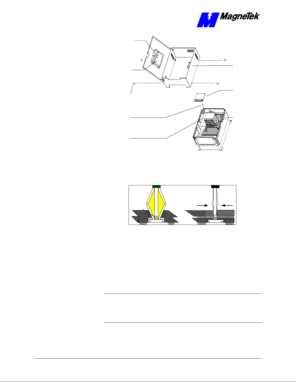
chassis
board
SMART TRAC Ethernet Card
12-pin wiring
harness on
Digital Operator
attached to
connector J4 on
Smart Trac
CPU Card
Digital
Operator
9-pin RS-232
cable
attached here
4mm screws
(4 places)
secure ring
to main
Standoffs (4
places)
secure each
board
Smart Trac
Board Stack
PC/104
9-pin RS-232
cable
connector J5
6. Using a 4.5mm hex head driver, remove four standoffs from the
topmost card.
7. Using the PC/104 extraction tool, remove the topmost card from the
stack.
Position
rectangular
"jacks"
around
edges of
PCBs
Squeeze to lift
cards apart
Figure 8. Using the PC/104 Extraction Tool.
8. Repeat step 8 above until all PC/104 cards have been removed.
9. To remove the Smart Trac PG card:
• Disconnect the 4CN connector on the PG card.
• Using a tubular extraction tool or pliers, squeeze the plastic,
spring-loaded retainer built-in to the long plastic standoff located
at the top of the PG card, just above connector J6.
• Using a PC/104 extraction tool, remove the card.
NOTE: The Smart Trac PG card requires unique handling. Wedge the extracting
tool between the PG card and the CPU card. The area between the terminal strip
on the CPU card and the serial numbered edge of the PG card can be lifted first,
then the opposite side (nearest TB1) on the PG card). Alternate sides until the
card is free of the CPU card.
10. To remove the Smart Trac CPU card:
34 •• Appendix D – Removing the Smart Trac Card Stack Technical Manual Smart Trac Ethernet Card
Page 37

SMART TRAC Ethernet Card
• Disconnect the card at the 2CN connector on the CPU card.
• The CPU card is secured with three plastic standoffs with spring-
loaded clips on the end. Squeeze the top of the standoffs (the clips)
with the special cylindrical removal tool, your fingers or needlenosed pliers and lift the CPU card from the Smart Trac Inverter
Control Card.
You have removed the entire card stack. The inverter card, considered part of
the drive, is in clear view.
Technical Manual Smart Trac Ethernet Card Appendix D – Removing the Smart Trac Card Stack •• 35
Page 38

Page 39

Glossary of Terms
SMART TRAC Ethernet Card
Application Layer
AUI
Bridges
CSMA/CD
Data Link layer
enterprise-wide LAN
hub
The seventh layer of the OSI networking model. This layer provides the
translation between an application program (which uses the network to move
data) and the network. When a program makes an API (Application Program
Interface) call, this layer determines the devices it must communicate with,
whether a communications session should be established between devices, and if
packet delivery must be guaranteed.
Acronym for Attachment Unit Interface. An AUI is a 15-pin connector, used to
connect a cable to a network interface card, that allows for the use of a
transceiver and is often used with a coaxial cable.
An intellignet device used to transmit data from one network segment or port to
another, according to a set of rules.
Acronym for Carrier Sense Multiple Access/Collision Detection. It is used to
manage collisions of data packets on the network. When a collision is detected,
it instructs each network card to stop transmitting, wait a random amount of
time, then listen for other data transmissions before proceeding to transmit data
frames.
The second layer of the OSI network model. This layer creates and interprets
frame types, and interprets the information received from the Physical Layer.
A Local Area Network (LAN) that serves more than one purpose, may network
devices physically separated by long distances, and may be connected to the
internet.
A connection device that receives a signal, then transmits it to the connected
devices.
IEEE 802.3
LED
Network Layer
NIC
PC/104 standard
Technical Manual Smart Trac Ethernet Card Glossary of Terms •• 37
The open network Ethernet standard, issued by the Institute of Electrical and
Electronics Engineers. The standard has sections to describe cable types, among
others.
Acronym for Light Emitting Diode.
The thrid layer of the OSI network model. It directs the flow of data from a
source to a destination through addressing and routing. It must do this in spite of
the fact that devices are not always on the same physical wire or segment.
Acornym for Network Interface Card. It is an adapter that transforms data into
signals for transfer across the transmission media to a destination device.
An embedded PC bus standard. The standard defines the mechanical size of a
self-stacking bus. Also an IEEE draft standard, called the P996.1 Standard for
Page 40

SMART TRAC Ethernet Card
Compact Embedded PC Modules, the PC/104 Specification, Version 2.1, July
1994, PC Consortium.
Physical Layer
Presentation Layer
router
Session Layer
topology
Transport Layer
UTP
The first layer of the OSI networking model. This layer provides a physical
connection for transmission of data bits over the network media and between
devices.The layer also maintains data integrity as it moves from source to
destination.
The sixth layer of the OSI network model. This layer translates and converts
data from one format to another as the data moves from one device to another
(i.e. ASCII to EBCDIC).
A device used to regenerate a signal's voltage and retransmit it, allowing longer
network lengths. Unlike bridges, a router does not have the intelligence to
distinguish signals directed to a device on the same segment and instead
retransmits it to all segments on the network. This generates more traffic on the
network than if a bridge were used.
The fifth layer of the OSI networking model. The layer manages connections
between two devices while they are communicating. It has built-in error
correction and recovery. It determines whether all information has been sent or
received between two networked devices.
The manner in which a network is configured, usually one or a combination of
bus, star, ring.
The fourth layer of the OSI networking model. This layer concerns itself with
the delivery of packets transmitted by the Network Layer. This may involve
error control of data to guarantee delivery of the packets.
Acronym for Unshielded Twisted Pair. UTP is a type of cable containing a pair
of wires that are twisted at regular intervals to prevent signal interference with
electrical noise. UTP is commonly used with 10Base-T Ethernet networks.
38 •• Glossary of Terms Technical Manual Smart Trac Ethernet Card
Page 41

Index
1
10Base2 5, 13
10Base5 5, 13
10Base-T 5–6, 9, 13
SMART TRAC Ethernet Card
DeviceNet Network Topology 8
diagnostics 5
digital operator 16, 18
using the 16
Digital Operator 23
DNS Server Error! Not a valid
bookmark in entry on page
16
DoD model 8
downloading 5
E
electrostatic sensitive discharge 11
Electrostatic Sensitive Discharge
11
enterprise-wide LAN 15
ESD 11
ESD 11
ESD Procedures 4, 11
Ethernet 10
extraction tool 34
A
address
gateway 15
loopback 17
TCP/IP 15
Addresses and subnet mask 15
administrator, LAN 15
Application Layer 8
application protocol 7
B
boot 16
bootup 16
bus 5, 8
C
Capabilities, Smart Trac DeviceNet
Card 5
Carrier Sense Multiple
Access/Collision Detection 8
configuration
network 15
TCP/IP 18
Configuring the Smart Trac
DeviceNet Card 15
CPU 33
D
Data Link layer 7–8
default network gateway 19
F
fault manager 23
G
gateway
default network 19
gateway addresses 15
General Capabilities 5
ground 11
H
Help Desk 25
Humidity 5
I
IEEE 802.3 5, 7
indicator lights 21
information, safety 4
Installation
Testing Card 21
Testing the Network 21
Installation, Smart Trac DeviceNet
Card 11
International Standards
Organization 7
Interrupt 15
Inverter 35
IPCONFIG 18
Technical Manual Smart Trac Ethernet Card Index •• 39
Page 42

SMART TRAC Ethernet Card
L
LAN
enterprise-wide network 15
LAN Administrator 15
LEDs 21
On-board Indicator Lights 21
Length
Network 9
loopback 17
M
media, transmission 7
Menu 16
N
names, symbol 23
NE2000 5
network
private 17
Network Configuration 15
Network Layer 7–8
Network Length 9
Networking 15
O
octet 15
ODVA 27
On-board Indicator Lights 21
Open Systems Interconnect 7
Operating Temperature 5
operator, digital 16, 18
Optional Parts 31
OSI model 7–8
OSI Model
application protocol 7
transmission media 7
R
report
problem 25
reset 16
RS-232 5
S
safety information 4
Session Layer 7
Smart Trac AC1
on a DeviceNet Network 5
Smart Trac Workstation 16
static electricity 4, 11
Status and Error Messages 23
strap
wrist 11
symbol names 23
T
TCP/IP 5, 8, 15–18
TCP/IP Address 15
TCP/IP Configuration 18
Technical Manual 4, 11
Testing the Network 21
tool, extraction 34
Topology 8
Bus 5, 8
Transmission Control
Protocol/Internet Protocol 8
transmission media 7
Transport Layer 7–8
Troubleshooting
DeviceNet Network Problems 23
Status and Error Messages 23
Troubleshooting 25
Troubleshooting Your Smart Trac
DeviceNet Card 23
P
parts
optional 31
PC/104 27
Physical Layer 7–8
PING 18
Presentation Layer 7
private network 17
Problem Report 25
protocol 5, 7–8, 16, 24
U
Unpacking 11
uploading 5
Using the Digital Operator 16
W
Warranty 4
Windows NT 16
workstation, Smart Trac 16
wrist strap 11
Q
Quick Start 6
40 •• Index Technical Manual Smart Trac Ethernet Card
Page 43

SMART TRAC Ethernet Card
Data subject to change without notice. Smart Trac is a trademark of MagneTek, Inc. MicroTrac is a registered trademark of MagneTek, Inc. Microsoft, Windows and Windows NT are registered
trademarks of Microsoft Corporation
MagneTek
Drives and Systems
16555 West Ryerson Road
New Berlin, WI 53151
(800) 541-0939, (262) 782-0200, FAX (414) 782-3418
TM 3554-0060 © 1999-2000 MagneTek, Inc. 1/31/2000
 Loading...