

Page 1

Technical Manual
™
™
S
M
A
R
S
M
R
T
T
A
MagneTek, Inc. - Drives and Systems Division
T
T
R
R
A
A
C
C
O
O
Dii
D
p
err
p
e
giitt
g
att
a
all
a
orr
o
Page 2

Page 3

SMART TRAC AC1
Contents
Operator Driver Installation 1
Installing the Smart Trac Operator Driver.................................................................................................1
The Smart Trac AC1 Digital Operator 5
Identifying Controls and Indicators.............................................................................................................5
Controls.............................................................................................................................................5
Indicators...........................................................................................................................................6
Using the Digital Operator..........................................................................................................................10
Selecting a Secondary Language.....................................................................................................11
Loading Application Settings ..........................................................................................................11
Display Faults .................................................................................................................................12
Display of Fault Information...........................................................................................................12
Digital Operator Menu Tree.......................................................................................................................13
Digital Operator Special Functions Menu Tree........................................................................................14
Glossary of Terms 15
Index 17
Engineer's Guide Smart Trac Digital Operator Contents •• i
Page 4

Page 5

THIS PAGE INTENTIONALLY LEFT BLANK
SMART TRAC AC1
Engineer's Guide Smart Trac Digital Operator Contents •• i
Page 6

Page 7
SMART TRAC AC1
Operator Driver Installation
Installing the Smart Trac Operator
Driver
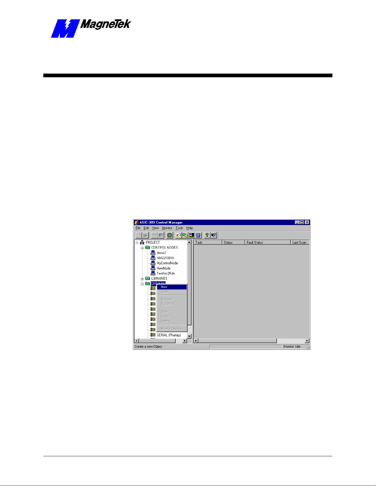
1. Click START, PROGRAMS, MAG-300, CONTROL MANAGER.
The Control Manager software loads.
2. Expand the Project folder tree and right click the Drivers folder. A
selection box appears with New… highlighted.
Figure 1. The New Device Driver Selection box.
3. Click the New selection box. The Install Driver dialog box appears.
Engineer's Guide Smart Trac Digital Operator Operator Driver Installation •• 1
Page 8

Figure 2. I/O Driver Install dialog box.
To view driver .dll files, you
must select View All Files in
Windows NT Explorer. If you
have Windows NT without
IE4.0 installed: from
Explorer, click View,
Options, click View tab. In
Hidden Files, click Show all
files If you have IE4.0
installed: from Explorer, click
View, Folder Options,
click the View tab. In
Advanced Settings, click
Show All Files in the
Hidden files folder.
4. Click the small box containing three dots (…) to the far right of the
Data File (*.ini) box. This allows you to browse for the initialization
file on your system (generally the driver will be installed from your
CD_ROM). For our example, we assume the file is on a floppy in the
A: drive. Find the file Operator.ini and OPEN it. Two more boxes,
for entry of Config.exe and Help.exe, become active.
5. Click the small box containing three dots (…) to the far right of the
Config (*.exe) box. Browse for the Operator.EXE file. Press TAB
or ENTER. More boxes will become active.
6. Click the small box containing three dots (…) to the far right of the
Help (*.chm) box. Browse for the STOperatorEM.CHM file. Press
TAB or ENTER. The screen should look like the following (if
installing from the A:\ drive).
2 •• Operator Driver Installation Engineer's Guide Smart Trac Digital Operator
Page 9

SMART TRAC AC1
Figure 3 The completed example DeviceNet Driver Install screen
7. Click INSTALL. When finished, you are returned to Control Manager.
The driver name should appear in its own folder within the Drivers
folder.
8. The Operator card library is ready for use.
Engineer's Guide Smart Trac Digital Operator Operator Driver Installation •• 3
Page 10

THIS PAGE INTENTIONALLY LEFT BLANK
4 •• Operator Driver Installation Engineer's Guide Smart Trac Digital Operator
Page 11

SMART TRAC AC1
The Smart Trac AC1 Digital
Operator
Identifying Controls and Indicators
The face of the Smart Trac AC1 contains an eleven-key keypad for data input, a
two-line by sixteen-character LCD display and LED’s to provide status
information.
Controls
Digital
Operator
LCD Display
Keypad
Figure 4. Typical Smart Trac AC1 with keypad and LCD display.
An RS-232 port, also located on the face of the Smart Trac AC1, provides one
means to connect a personal computer to the unit (optional communications
cards providing other means).
Two types of controls exist on the Smart Trac AC1: DATA and CONTROL.
• The DATA group includes keys labeled MENU, UP, DOWN, RIGHT,
ESCAPE and DATA/ENTER. These keys allow setting or viewing of
Engineer's Guide Smart Trac Digital Operator The Smart Trac AC1 Digital Operator •• 5
Page 12

SMART TRAC AC1
data including parameters, feedbacks and selection and use of special
functions.
• The CONTROL group includes the keys labeled LOCAL/REMOTE,
JOG, FWD/REV, RUN and STOP. These keys provide control over
the operation of the Smart Trac AC1. Although labeled for "typical"
use, they may be programmed to operate differently. Consult the
documentation specific to your Smart Trac AC1.
Indicators
Indicators include seven status lights labeled DRIVE, FWD, REV,
REMOTE/SEQ and REMOTE/REF, RUN and STOP, and the LCD display
showing status, fault or parameter information. What causes these lights to be
triggered on or off is entirely up to the application program.
The behavior of each of these controls and indicators is described in tables and
the figures that follow:
Indicator
Lights
CONTROL
Group
RUN/STOP
Indicator
Lights in
Buttons
Figure 5. The CONTROL Group of the Smart Trac AC1 Digital Operator.
DATA
Group
Figure 6. The DATA group of the Smart Trac AC1 Digital Opertor.
6 •• The Smart Trac AC1 Digital Operator Engineer's Guide Smart Trac Digital Operator
Page 13

SMART TRAC AC1
Engineer's Guide Smart Trac Digital Operator The Smart Trac AC1 Digital Operator •• 7
Page 14

SMART TRAC AC1
Indicator
Lamp
DRIVE
FWD
REV
REMOTE/
SEQ
Table 1. Digital Operator Indicators
Digital Operator Indicators
Function
Red light - programmable.
Typically lights (ON) when Smart Trac AC1 is in Drive mode of
operation.
Red light – programmable.
Typically lights (ON) when FWD motor direction is selected.
Red light – programmable.
Typically lights (ON) when REV motor direction is selected.
Red light – programmable.
Typically ON when Smart Trac AC1 is operating from external RUN
and STOP signals.
REMOTE/
REF
RUN
STOP
8 •• The Smart Trac AC1 Digital Operator Engineer's Guide Smart Trac Digital Operator
Red light – programmable.
Typically ON when Smart Trac AC1 operating by an external frequency
reference signal.
Red light – programmable.
Typically OFF when Smart Trac AC1 is in stopped condition. Typically
lights steadily (ON) when Run signal is active. It blinks after Stop
signal has been received and Smart Trac AC1 is ramping down.
Red light – programmable.
Typically, lights steadily (ON) at initial power-up. Typically blinks after
Run signal becomes active but frequency reference is zero. Typically off
when Smart Trac AC1 is controlling motor speed.
Page 15

SMART TRAC AC1
Key Label Function
LOCAL/
REMOTE
JOG
FWD/REV Programmable.
RUN
STOP
MENU
ESC
Table 2. Digital Operator Control Keys
Digital Operator Control Keys
Programmable.
Typically programmed to toggle between the Digital Operator and
Remote (terminal) modes of operation. Active only when Smart Trac
AC1 is in stopped condition.
Programmable.
Typically programmed to initiate Jog function while pressed and held
in drive mode. Smart Trac AC1 output goes to programmed Jog
Frequency to check motor operation, or to position the machine. When
key is released, output returns to zero and motor stops. If motor is
running, pressing this key will have no effect. May be programmed to
be disabled if Smart Trac AC1 is programmed to use an external JOG
input.
Typically programmed to toggle between motor run Forward and
Reverse with each press of key. Selected direction is indicated by
FWD or REV lights. If selection is made while Smart Trac AC1 is
stopped, it determines direction motor will run when started. If
selection is changed during running, Smart Trac AC1 will ramp motor
to zero speed and then ramp it up to set speed in opposite (i.e. newly
selected) direction.
Programmable.
Typically programmed to operate by external RUN and STOP signals
(as indicated by REMOTE SEQ lamp being lit). Pressing key will
produce a Run command to initiate Smart Trac AC1 output to motor.
However, output frequency will be zero if frequency reference is zero
at time key is pressed.
Programmable.
Typically programmed to produce a Stop command when key pressed.
Smart Trac AC1 will decelerate motor in programmed stopping
manner, then Smart Trac AC1 output will be disconnected from the
motor.
After power-up, displays top level of digital operator menu tree,
Numeric Parameters. At the topmost level of five menus, it moves
from menu to menu in the following order: Numeric Parameters,
Numeric Feedbacks, Logic Parameters, Logic Feedbacks, and Special
Functions.
If within a submenu, returns to the topmost menu, Numeric
Parameters.
Returns display to previous level in menu tree or to status before
pressing DATA/ENTER.
Engineer's Guide Smart Trac Digital Operator The Smart Trac AC1 Digital Operator •• 9
Page 16

SMART TRAC AC1
Digital Operator Control Keys
Key Label Function
DATA/
ENTER
Moves to a submenu after selected with UP and DOWN arrow keys.
Writes a keyed parameter value into Smart Trac memory.
>RESET
up arrow
down arrow
Moves blinking cursor of a value being changed one digit to the right if
modifying either a numeric parameter or the password. If at the rightmost position, wraps around to first position on left side of display.
OR
Resets a Smart Trac AC1 fault or fault history list.
Moves to a previous menu or submenu within a menu level. At the
topmost level of five menus, it moves from menu to menu in the
following order: Numeric Parameters, Special Functions, Logic
Feedbacks, Logic Parameters, and Numeric Feedbacks
Moves to the next menu or submenu within a menu level. At the
topmost level of five menus, it moves from menu to menu in the
following order: Numeric Parameters, Numeric Feedbacks, Logic
Parameters, Logic Feedbacks, and Special Functions.
Using the Digital Operator
You may use the Up and
Down arrow keys to move
from menu to menu or
submenu to submenu within a
menu level.
10 •• The Smart Trac AC1 Digital Operator Engineer's Guide Smart Trac Digital Operator
When the Smart Trac AC1 is powered-up, the text window of the digital
operator displays the message "Press the MENU key now…". Each press of the
MENU key displays the next menu. There are five menus: Numeric
Feedbacks, Numeric Parameters, Logic Feedbacks, Logic
Parameters, and Special Functions. Each menu contains sub-menus.
1. To get familiar with the menu structure:
2. Press the MENU key. The first menu, Numeric Parameters, appears.
3. Press DATA/ENTER. You see the first numeric parameter, as
programmed.
Page 17

SMART TRAC AC1
4. Press the up arrow. You see the last numeric parameter, as
programmed.
5. Press the ESC key. You are returned to the Numeric Parameters menu.
6. Press the MENU key again. The second menu, Numeric Feedbacks,
appears. Continue to press MENU through the Logic Parameters
list, the Logic Feedbacks list, to the Special Functions menu list.
Selecting a
Secondary Language
Loading Application
Settings
Your Smart Trac AC-1 may have been programmed to display legends and units
in a secondary, or alternate, language. The primary language is always English
and may not be changed. Either the primary (English) or secondary (alternate)
language may be displayed by the user. You choose to use a secondary language
in the Special Functions menu.
1. On the digital operator, press MENU until you get to the Special
Functions menu.
2. Press DATA/ENTER. A message appears "Set Language, press
DATA/ENTER."
3. Press DATA/ENTER. The message "Present Language" appears
with either English or Secondary below it, indicating the language
currently in use.
4. Press the UP or DOWN arrow keys until you reach the English or
Secondary Language labels, depending on which you'd like to use.
Press DATA/ENTER to select the use of the language.
5. When done, press Menu to return to the top-level menu.
You can choose to accept all application (default) settings as defined in your
application program. These include defaults for Numeric Parameters and Logic
Parameters.
1. Press MENU on the digital operator. The words Numeric
Parameters appear, indicating you are in the Numeric Parameters
menu.
2. Press the MENU key again. The second menu, Numeric Feedbacks,
appears. Continue to press MENU through the Logic Parameters
list, the Logic Feedbacks list, to the Special Functions menu list.
3. Press DATA/ENTER. The submenu Set Language appears.
4. Press the UP and DOWN arrow keys until you get to the submenu
Newest Faults.
5. Press DATA/ENTER. The message "Load Defaults, press
DATA/ENTER" appears.
6. Press DATA/ENTER. The message "Are you sure?" appears with
"No-keep data" below it.
7. Press UP or DOWN arrow keys and select between "No-keep data"
and "Yes-Load Default". Press DATA/ENTER to select the
indicated action.
8. When done, press Menu to return to the top-level menu.
Engineer's Guide Smart Trac Digital Operator The Smart Trac AC1 Digital Operator •• 11
Page 18

SMART TRAC AC1
Display Faults
Display of Fault
Information
You can read any of the newest or oldest faults on the digital operator:
1. Press MENU on the digital operator. The words Numeric
Parameters appear, indicating you are in the Numeric Parameters
menu.
2. Press the MENU key again. The second menu, Numeric Feedbacks,
appears. Continue to press MENU through the Logic Parameters
list, the Logic Feedbacks list, to the Special Functions menu list.
3. Press DATA/ENTER. The submenu Set Language appears.
4. Press the UP and DOWN arrow keys until you get to one of the
submenus, Newest Faults or Oldest Faults, whichever you'd like to
review.
5. Press DATA/ENTER. The first fault in the queue appears.
6. To review other faults, press the UP and DOWN arrow keys.
7. When done, press Menu to return to the top-level menu.
The digital operator shows any Smart Trac AC1 or program faults before any
other information. The first fault to occur is displayed. Once cleared, by
pressing any key on the digital operator, a second fault, if present, is displayed.
Clearing acknowledges that the operator has been notified of the fault. When a
fault is cleared, it is no longer annunciated, but is still active.
If a priority fault is cleared through the Smart Trac ARCNET LAN, it is
immediately removed from the local display on the digital operator.
A list of active faults may be viewed. The faults remain on this list until their
triggering condition is removed and >RESET is pressed.
Annunciated faults are also logged into the oldest and newest faults history lists.
These lists can be viewed. Pressing >RESET while viewing one of the history
lists will clear all the faults in that list.
Once active faults are reset, menu items will be displayed.
12 •• The Smart Trac AC1 Digital Operator Engineer's Guide Smart Trac Digital Operator
Page 19

Digital Operator Menu Tree
LEVEL 1 LEVEL 2 LEVEL 3
Press the Menu
key to begin.
MENU
Numeric Parameters
MENU
Numeric Feedbacks
MENU
Logic Parameters
MENU
Logic Feedbacks
MENU
Special Functions
MENU
OR
OR
OR
OR
OR
OR
UP
DOWN
UP
DOWN
UP
DOWN
UP
DOWN
UP
DOWN
UP
DOWN
Use up and down arrow keys
to scroll through the options
and parameters within a level
DATA
ENTER
Numeric Parameter 1
#1 (Value) Units
Numeric Parameter X
DATA
ENTER
DATA
ENTER
DATA
ENTER
DATA
ENTER
#Z (Value) Units
Numeric Feedback 1
#Z (Value) Units
Numeric Feedback X
#Z (Value) Units
Logic Parameter 1
Logic Parameter X
Logic Feedback 1
Logic Feedback X
See next page for
Functions Menu
Number of parameters
or feedbacks displayed
depends on number of
entries in Operator
Configurator
the Special
Tree
DATA
ENTER
DATA
ENTER
DATA
ENTER
DATA
ENTER
Legend
NNNN (Value) AAA (units)
*
Legend
NNNN (Value) AAA (units)
*
Reset Counter
ON
Reset Counter
OFF
Legend
NNNN (Value) AAA (units)
*
SMART TRAC AC1
Each press of
>RESET moves one
digit to right starting
with leftmost digit.
DATA
ENTER
Maximum
Limit?
No
Minimum
Limit?
No
DATA
ENTER
*
Asterisk denotes logic branch not
shown that is identical to Numeric
Parameters branch in dashed line
rectangle above..
^Limit^ Exceeded
Yes
Press ESC key
Limit Exceeded
Yes
Press ESC key
ESC
Use up and down arrow keys
to scroll through the options
and parameters within a level
Figure 7. AC1 Digital Operator Menu Tree
Engineer's Guide Smart Trac Digital Operator The Smart Trac AC1 Digital Operator •• 13
Page 20

LEVEL 1
LEVEL 2
LEVEL 3
SMART TRAC AC1
Digital Operator Special Functions
Menu Tree
Special Functions
UP
MENU
OR
DOWN
Use up and down arrow keys
to scroll through the options
and parameters within a level
DATA
ENTER
Active Faults
#1 press ENTER
Oldest Faults
#2 press ENTER
Newest Faults
#3 press ENTER
Load Defaults
#4 press ENTER
Set Clock
#5 press ENTER
Password Entry
#6 press ENTER
Set Language
#7 press ENTER
TCP/IP Settings
#8 press ENTER
Firmware Version
#9 press ENTER
COM1 Config
#10 press ENTER
DATA
ENTER
DATA
ENTER
DATA
ENTER
DATA
ENTER
DATA
ENTER
DATA
ENTER
DATA
ENTER
DATA
ENTER
DATA
ENTER
DATA
ENTER
(1st most recent Active
Fault)
(to 20th most recent
Active Fault)
(1st Oldest Fault)
(to 20th Oldest Fault)
(1st Newest Fault)
(to 20th Newest Fault)
Are you sure?
No-Keep Data
Are you sure?
Yes-Load Default
Current Time
DDMMMYY HH:MM:SS
Enter the pswrd
Present Language
English
Present Language
Secondary
IP Address
NNN:NNN:NNN:NNN
Subnet Mask
NNN:NNN:NNN:NNN
Gateway Address
NNN:NNN:NNN:NNN
Boot Code
Version N.N.NN
Monitor
Version N.N.NN
Operating System
Version N.N.NN
Baud Rate
UP
DOWN
UP
DOWN
UP
DOWN
UP
DOWN
DATA
ENTER
UP
DOWN
UP
DOWN
UP
DOWN
FAULT LABEL
YY MMM DD HH:MM:SS
DATA
ENTER
FAULT CODE #
NNNNN
DATA
ENTER
DATE/TIME Flashes
DATA
ENTER
14 •• The Smart Trac AC1 Digital Operator Engineer's Guide Smart Trac Digital Operator
Page 21

Glossary of Terms
SMART TRAC AC1
active fault
priority fault
Any fault that has not been reset.
The fault preventing a drive from functioning; the topmost level of faults. Faults
may be assigned priorities using the Fault Manager.
Engineer's Guide Smart Trac Digital Operator Glossary of Terms •• 15
Page 22

SMART TRAC AC1
THIS PAGE INTENTIONALLY LEFT BLANK
16 •• Glossary of Terms Engineer's Guide Smart Trac Digital Operator
Page 23

K
keypad 5
L
SMART TRAC AC1
Index
A
active faults 14
Annunciated faults 14
C
communications 5
CONTROL group 6
Controls 5
D
DATA group 5
digital operator 5, 12, 14
menu tree 11, 15, 16
using the 12
Display Faults 14
Display of Fault Information 14
F
fault
annunciation 14
faults
display 14
program 14
faults 6, 12, 14
Feedbacks, Logic 13
functions, special 6, 11
Lamp, Indicator 10
language
primary 13
secondary 13
language, secondary 13
Loading Application Settings 13
Logic Feedbacks 13
Logic Parameters 13
M
menu
Special Functions 13
Menu 5, 15, 16
Menu Tree 11, 15, 16
N
Numeric Parameters 13
O
operator, digital 512, 14
P
parameters
application 6, 13
Parameters
Numeric 13
Parameters, Logic 13
port, RS-232 5
primary language 13
program faults 14
R
reset 12, 14
RS-232 port 5
S
G
group
control 6
data 5
I
Indicator 5
Engineer's Guide Smart Trac Digital Operator Index •• 17
Secondary Language 13
Settings 2
Special Functions 6, 11
Special Functions menu 13
U
Using the Digital Operator 12
Page 24

SMART TRAC AC1
18 •• Index Engineer's Guide Smart Trac Digital Operator
Page 25

SMART TRAC Digital Operator
Data subject to change without notice. Smart Trac is a trademark of MagneTek, Inc. MicroTrac is a registered trademark of MagneTek, Inc. Microsoft, Windows and Windows NT are registered
trademarks of Microsoft Corporation
MagneTek
Drives and Systems
16555 West Ryerson Road
New Berlin, WI 53151
(800) 541-0939, (262) 782-0200, FAX (262) 782-3418
TM 3554-0002 © 1999-2000 MagneTek, Inc. 01/31/2000
 Loading...