

Page 1

Technical Manual
™
™
S
M
A
R
S
M
D
evviicc
D
e
A
R
e
e
T
T
N
N
T
R
T
R
ett
e
A
A
C
C
C
C
arr
a
d
d
Page 2

Page 3

SMART TRAC DeviceNet Card
Contents
Important Safety and Warranty Information 1
Warnings, Cautions and Notes.....................................................................................................................1
General Safety Precautions - Warnings ......................................................................................................2
Important Warranty Information................................................................................................................2
Smart Trac DeviceNet Card 3
General Capabilities......................................................................................................................................3
Smart Trac AC1 on a DeviceNet Network ..................................................................................................3
Specifications .................................................................................................................................................4
Quick Start.....................................................................................................................................................4
DeviceNet Basics 5
Introduction...................................................................................................................................................5
DeviceNet Network Topology..........................................................................................................6
Network Length ................................................................................................................................7
Thick Cable Specifications................................................................................................................8
Thin Cable Specifications .................................................................................................................8
Terminating Resistor Specifications .................................................................................................9
DeviceNet Connector........................................................................................................................9
Installing the Smart Trac DeviceNet Card 11
Unpacking ....................................................................................................................................................11
Electrostatic Sensitive Discharge (ESD) Procedures ......................................................................11
Unpacking Procedure......................................................................................................................11
Installing the Smart Trac DeviceNet Card................................................................................................11
Connecting the Smart Trac DeviceNet Card to a DeviceNet Network...................................................13
Configuring the Smart Trac DeviceNet Card 17
Configuration...............................................................................................................................................17
Default Settings............................................................................................................................................17
Non-Default Settings ...................................................................................................................................17
Interrupt...........................................................................................................................................17
Base I/O Address.............................................................................................................................18
Testing Card Installation 19
Testing the Network....................................................................................................................................19
General Test Parameters..................................................................................................................19
Network Termination & Signal Wires ............................................................................................19
Shield ..............................................................................................................................................19
Grounding .......................................................................................................................................19
Technical Manual 3554-0070 Contents •• i
Page 4

SMART TRAC DeviceNet Card
Network Power - Minimum supply voltage....................................................................................20
Network Power - Common Mode Voltage......................................................................................20
MAC ID/ Baud Rate Settings..........................................................................................................20
On-board Indicator Lights .........................................................................................................................20
Module and Network Status LEDs at Power-Up......................................................................................22
Troubleshooting Your Smart Trac DeviceNet Card 23
Status and Error Messages.........................................................................................................................23
Troubleshooting DeviceNet Network Problems........................................................................................25
Appendix A – Technical Support 27
Technical Support .......................................................................................................................................27
References ....................................................................................................................................................27
Problem Report ...........................................................................................................................................28
Appendix B – Replaceable Parts 29
Replaceable Parts Listing ...........................................................................................................................29
Appendix C – Removing the Smart Trac Card Stack 31
General Procedures.....................................................................................................................................31
Glossary of Terms 35
Index 37
ii •• Contents Technical Manual 3554-0070
Page 5

SMART TRAC DeviceNet Card
Important Safety and Warranty
Information
Warnings, Cautions and Notes
WARNING
A statement of conditions which MUST BE OBSERVED to
prevent personal injury or death.
WARNING - ESD
A statement of conditions which must be observed to prevent
damage to components due to ESD (ElectroStatic Discharge) and
to prevent personal injury or death.
CAUTION
A statement of conditions which must be observed to prevent
undesired equipment faults, Smart Trac AC1 system degradation
and damage to equipment.
IMPORTANT
A statement of conditions which should be observed during Smart Trac AC
DeviceNet setup or operation to ensure dependable service.
NOTE: Notes indicate information that is in addition to a discussion of the topic
in adjoining text. Alternatively, it may limit or restrict the paragraph(s) that
follow(s) to specific models or conditions.
TIP - Tips indicate information that should make a procedure easier or more
efficient.
Technical Manual 3554-0070 Important Safety and Warranty Information •• 1
Page 6

SMART TRAC DeviceNet Card
General Safety Precautions Warnings
Important safety information follows. Please read and understand all
precautions listed below before proceeding with the specification, installation,
set-up or operation of your Smart Trac AC1. Failure to follow any of the
following precautions may result in personal injury or death, or damage to the
equipment.
WARNING - ESD
The Control Printed Circuit Board (PCB) employs CMOS
Integrated Circuits that are easily damaged by static electricity.
Use proper ElectroStatic Discharge (ESD) procedures when
handling the Control PCB. See Smart Trac AC1 Technical Manual
for details. Failure to comply may result in damage to equipment
and/or personal injury.
Important Warranty Information.
Do not modify your Smart Trac AC1, its components, or any of the procedures
contained in the technical documentation supplied by MagneTek. Any
modification of this product by the user is not the responsibility of MagneTek
and will void the warranty.
2 •• Important Safety and Warranty Information Technical Manual 3554-0070
Page 7

SMART TRAC DeviceNet Card
Smart Trac DeviceNet Card
General Capabilities
Adding the Smart Trac DeviceNet Card to your Smart Trac AC1 makes it fully
compatible with other industrial devices (i.e., drives, limit switches, operator
interfaces, programmable controllers) conforming to the DeviceNet standard. It
also complies with CAN (Controller Area Network) specification 2.0, parts A
and B, Standard Frame Identifiers.
The card also conforms to PC/104 specifications and has its own central
processing unit (CPU). It supports DeviceNet data rates of 125 Kbaud, 250
Kbaud and 500 Kbaud.
While DeviceNet supports up to 64 nodes identified by MAC IDs, the Smart
Trac DeviceNet card uses one MAC ID, leaving 63 other device nodes available
to be addressed.
The Smart Trac DeviceNet driver supports Polled I/O and Bit Strobed I/O
connections as well as explicit messaging. It supports all ODVA (Open
DeviceNet Vendor Association) approved devices.
Smart Trac AC1 on a DeviceNet
Network
With a Smart Trac DeviceNet card and driver installed and connected to a
DeviceNet network, the Smart Trac AC1 communicates in a Master/Slave
relationship (as opposed to peer-to-peer). A Smart Trac AC1 with an installed
Smart Trac DeviceNet card serves as Master of a DeviceNet network. The
Master gathers and distributes I/O data for the process controller. It also gathers
I/O data from Slave devices and distributes the data to Slave devices.
On a DeviceNet Master/Slave network, a Master device "owns" a Slave device.
A Slave device can be "owned" by only one Master. Except for a check for
duplicate MAC IDs, a slave cannot initiate communication transactions unless it
has been told to do so by its Master. The Master (in this case, the Smart Trac
DeviceNet card) scans its Slave devices based on a scan list that it contains. The
Slaves' MAC IDs appear in the Master's scan list of I/O addresses to be scanned
by the card at specified intervals.
Smart Trac systems support single master networks. Only one Smart Trac
DeviceNet Card is allowed per network.
Technical Manual 3554-0070 Smart Trac DeviceNet Card •• 3
Page 8

SMART TRAC DeviceNet Card
Specifications
• 16 MHz V40 microprocessor with 128 Kbytes RAM
• Software configurable interrupts 2, 5 and 7 (7 normally used)
• DeviceNet compatible 5-pin connector
• Network status bicolor indicator
• Operating temperature 32° to 104°F (0° to 40° C)
• Storage temperature -4° F to 140°F (-20° to 60° C)
• Operating Humidity 5% to 90% non-condensing
• Supports standard DeviceNet baud rates of 125, 250 and 500 baud
• UCMM capable and supports Group 1, 2, and 3 dynamic connections.
• Accepts shielded twisted pair cable compatible with target network
Quick Start
1. Check DIP switch settings on the card against the default settings (see
“Default Settings"). You should use default settings except in only
unusual situations. Your Smart Trac Field Engineer can help you if you
need assistance.
2. Power OFF your Smart Trac AC1.
3. Install the card in your Smart Trac AC1 in a PC/104 option card
position (on top of the Smart Trac Ethernet Card or another PC/104
option card).
4. Connect the DeviceNet network cable.
5. If your power supply is not on a common circuit breaker with the Smart
Trac AC1, power up your DeviceNet network.
6. Power up your Smart Trac AC1.
7. Test your card installation.
4 •• Smart Trac DeviceNet Card Technical Manual 3554-0070
Page 9

DeviceNet Basics
Introduction
Originally developed by Bosch for the automotive industry, DeviceNet is a lowcost communications protocol to connect industrial devices (i.e., limit switches,
sensors, bar code readers, variable frequency drives, panel displays and operator
interfaces) to a network. DeviceNet provides an open network standard with
high noise immunity, suitable to industrial environments. The protocol includes
device-level diagnostics. It allows the addition of other devices on a network
without cycling power to the network.
SMART TRAC DeviceNet Card
Configuration Tool
+24 Volt
power supply
Controller
Network
DeviceNet
Other Devices
Motor
Starter
Barcode
Pushbutton
Cluster
Input/Output
Devices
Figure 1. Typical DeviceNet Network configuration
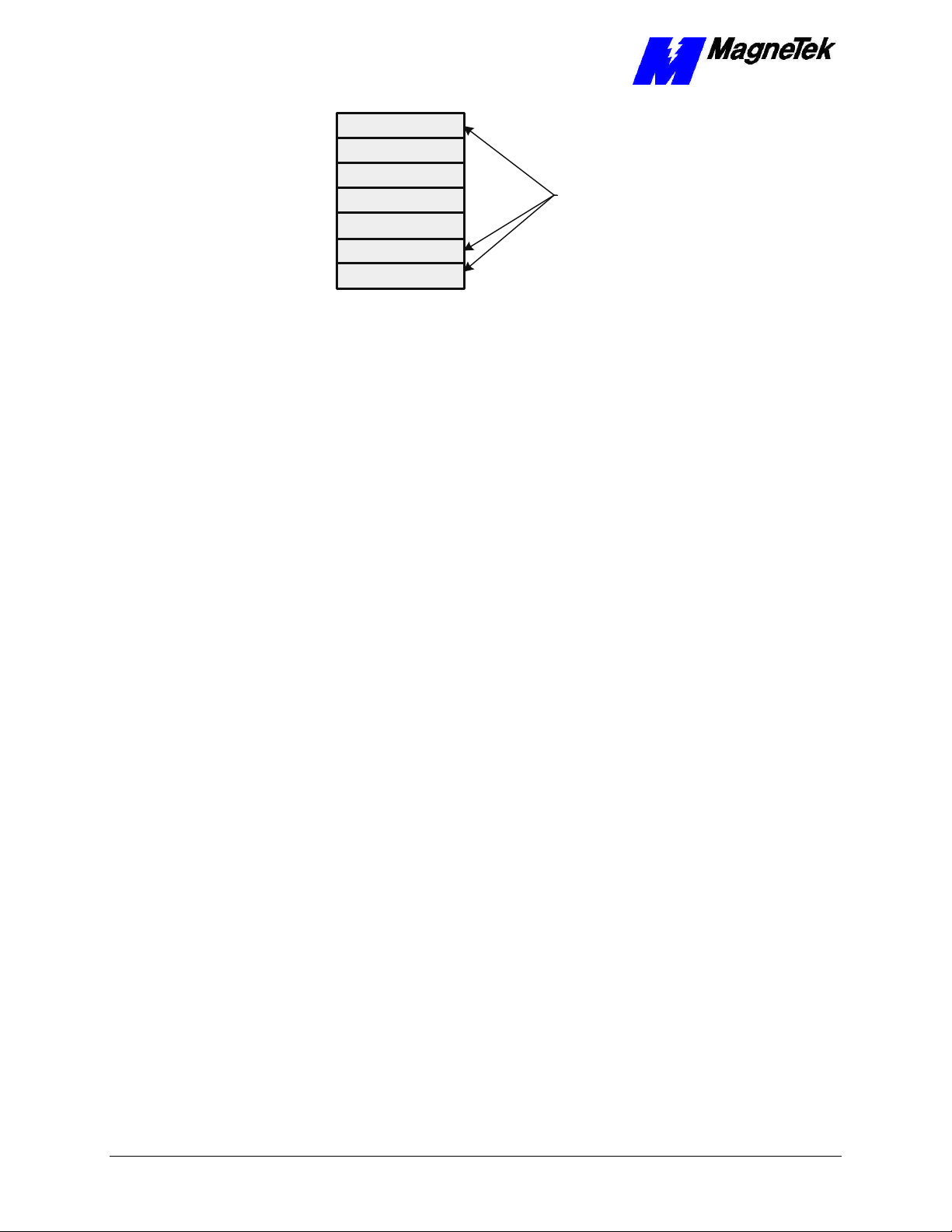
The Open Systems Interconnect (OSI), established in 1984 by the ISO
(International Standards Organization), divides network functions into seven
layers: Physical, Data Link, Network, Transport, Session, Presentation and
Application Protocol. DeviceNet provides the Application Protocol (highest
level 7), Data Link Layer (layer 2), Physical Layer (layer 1) and Transmission
Media (a sublevel of level 1, sometimes referred to as an eighth layer 0).
Smart Trac
AC1
Scanner
DeviceNet incorporates the CAN protocol to provide the Data Link Layer.
Technical Manual 3554-0070 DeviceNet Basics •• 5
Page 10
SMART TRAC DeviceNet Card
Application
Presentation
Session
Transport
Network
Data Link
Physical
Figure 2. DeviceNet and the OSI Model
• The Physical Layer transforms data into bits that are sent across the
physical media.
• The Data Link layer determines access to the network media in terms
of frames. Its Media Access Control (MAC) sublayer is responsible for
physical addressing.
• The Network Layer routes data through a large network.
• The Transport Layer provides end-to-end, reliable connections, often in
terms of segments.
DeviceNet provides
these layers of the
OSI (Open Systems
Interconnect) model.
DeviceNet Network
Topology
• The Session Layer allows users to establish connections using
intelligently chosen names in packets.
• The Presentation Layer negotiates data exchange formats, also in terms
of packets.
• Finally, the Application Layer provides the interface between the user's
application and the network through messages.
Data is said to move from layer to layer within the seven layers of the OSI
model. CAN (Controller Area Network)-based, DeviceNet permits networking
of up to 64 nodes, called Media Access Control Identifiers, or MAC-IDs. CAN
defines the syntax or form of the data movement. By adhering to the CAN
specification and using CAN Controller chips, DeviceNet completely defines the
Data Link layer of the OSI model.
Devices on DeviceNet networks are physically connected together in a linear
bus topology. All devices on the network are connected to one primary trunk
cable. You must install terminating resistors at the end of the trunk line. You
may install drop lines with lengths of up to 6 meters (20 feet) to attach one or
more nodes. The maximum number of drop lines and their lengths are subject to
maximum drop cable distances (see Table 1). DeviceNet allows for branching
structures only on the drop line. See "Figure 3 " for a typical DeviceNet
topology. In the figure, the thick line represents the trunk line of the network.
Thin lines represent drop lines.
6 •• DeviceNet Basics Technical Manual 3554-0070
Page 11

SMART TRAC DeviceNet Card
Multiple Node
Node
Node
Branching
Drop Line
Multi-Port
Tap
Node
Tap
Tap
Node
Node
Terminating
Resistor
Terminating
Resistor
Node
Zero Length
Drop Line
Network Length
Line Length with Thin
or Thick Cable
Node
Node
Tap
Node
Multi-Port
Tap
Node
Node
Multiple Node
Daisy Chain
Drop Line
Figure 3. Typical DeviceNet Topology.
In a DeviceNet network, end-to-end network (and point-to-point) distance varies
with network transmission speed (baud rate). You may use a combination of
thick and thin cable to construct trunk lines.
For trunk lines constructed of only one type of cable (either thick OR thin), refer
to Table 1. Remember that "network length" includes the combined length of
trunk line cable and drop line cable between the points.
Table 1. DeviceNet Network Length
DeviceNet Network Length
Speed
(Baud
Rate)
125 Kbps 1, 640 ft. (500m) 328 ft (100m)
250 Kbps 820 ft (250 m)
500 Kbps 328 ft. (100m) 328 ft (100m)
Maximum Length Allowed
(Thick Trunk Length)
Maximum Length Allowed
(Thin Trunk Length)
328 ft (100m)
Maximum Drop Length 20 ft (6m) (Drop line length is the longest cable
distance measured from the tap on the trunk line to each of the
transceivers of the nodes on the drop line).
Cumulative Drop Length 512 ft (156 m) at 125 Kpbs; 256 ft (78m) at
250 Kbps; or 128 ft (39m) at 500 Kbps
Data Packets: 0-8 bytes
Bus Topology: Linear (trunkline/dropline) with power and signal on the
same network cable.
Bus Addressing: Peer-to-Peer with Multi-Cast (one-to-many) or Multi-
Master and Master/Slave special case; polled or change-of-state
(exception-based)
Technical Manual 3554-0070 DeviceNet Basics •• 7
Page 12

SMART TRAC DeviceNet Card
System Features: Removal and replacement of devices from the
network under power.
Line Length with both
Thick and Thin Cables
When using a combination of thin and thick cable in a DeviceNet network,
calculate the maximum cable distance according to Figure 4 and the following
formulae:
At 125 Kbps: L
At 250 Kbps: L
At 500 Kbps: L
(L
is length of thick cable and L
thick
+ 5.0 * L
thick
+ 2.5 * L
thick
+ L
thick
= 500
thin
= 250
thin
= 100
thin
is length of thin cable)
thin
100
80
Length of Thin
Cable (meters)
60
40
20
125
500
Kbps
0
Length of Thick Cable (meters)
250
Kbps
200100 300 400 5000
Kbps
Figure 4. Combined Thin and Thick Cable Length Determination
Thick Cable
Specifications
Thin Cable
Specifications
Thick cable consists of two shielded pairs twisted on a common axis with a
drain wire in the center. An overall braid shield covers the shield pairs. Thick
cable is typically used for trunk lines.
The thick cable specified for DeviceNet network connections consists of:
• One (1) twisted signal pair (#18): blue/white
• One (1) twisted power pair (#15): black/red
• Separate aluminized Mylar shields around power pair and signal pair
• Overall foil/braid shield with drain wire (#18): bare
Thinner and more flexible than than Thick Cable, use Thin Cable for drop lines
or for shorter distance trunk lines.
The thin cable specified for DeviceNet network connections consists of:
• One twisted signal pair (#24): blue/white
• One twisted power pair (#22): black/red
• Separate aluminized Mylar shields around power pair and signal pair
• Overall foil/braid shield with drain wire (#22): bare
8 •• DeviceNet Basics Technical Manual 3554-0070
Page 13

Terminating Resistor
Specifications
SMART TRAC DeviceNet Card
You must install a terminating resistor at the farthest ends of a trunk line (and
only two per network). These terminating resistors must be 121 ohm, 1% Metal
Film, 1/4 Watt resistors.
NOTE: DO NOT install terminating resistors at the end of drop lines.
DeviceNet Connector
Your Smart Trac DeviceNet card ships with one female DeviceNet connector. It
mates with a male connector mounted on the card. The pinout of DeviceNet
connectors is described in Table 2.
Technical Manual 3554-0070 DeviceNet Basics •• 9
Page 14

SMART TRAC DeviceNet Card
THIS PAGE INTENTIONALLY LEFT BLANK
10 •• DeviceNet Basics Technical Manual 3554-0070
Page 15

SMART TRAC DeviceNet Card
Installing the Smart Trac
DeviceNet Card
Unpacking
Electrostatic
Sensitive Discharge
(ESD) Procedures
Unpacking Procedure
WARNING WARNING -- ESD ESD
Keep electronic circuit boards in Electrostatic Sensitive Discharge
(ESD) protective bags when not being handled. Use proper ESD
procedures (including an ESD wrist strap) when handling circuit
boards. Failure to comply may result in damage to equipment.
When working with an electrostatic sensitive discharge (ESD) device, you
should be grounded at all times. The easiest and most common way to provide
this ground is to use an approved ESD wrist strap. The strap is secured to your
wrist with a wire attached to the strap and clipped or taped to the chassis of the
unit being worked on. Any static is dissipated through the wire to ground,
greatly reducing the possibility of damage to the device.
It is a good idea to touch the chassis with your finger before handling any
electrostatic sensitive device. Any static electricity will be discharged to chassis
ground and will not be transferred to the device.
Always store devices (cards, other electronic components) in ESD protective
bags when not being handled.
Remove the protective shipping and packing material from the card. Ensure
contact wedges and other shipping devices have been removed.
Installing the Smart Trac DeviceNet
Card
The Smart Trac DeviceNet Card is PC/104 compatible, so it may be positioned
on the very top of the Smart Trac card stack.
NOTE: If replacing or adding a Smart Trac DeviceNet card to an existing Smart
Trac card stack, see "Appendix C – Removing the Smart Trac Card Stack"
before continuing.
Technical Manual 3554-0070 Installing the Smart Trac DeviceNet Card •• 11
Page 16

DeviceNet
SMART TRAC DeviceNet Card
Standoffs (4
places on top of
each card)
4CN
Connector
card in one of
top two stack
positions in
stack
Optional
PC/104
Card
Smart Trac
Ethernet
Card
Smart Trac
PS Card
Smart Trac
PG Card
2CN
Connector
Smart Trac
CPU Card
Inverter Control
Card
Adapter
Ring
Main Chassis
Figure 5. Smart Trac DeviceNet Card Stack Position
1. To install the DeviceNet card, orient the pins on the card with the
female pin connector on the card below it (normally the Ethernet card).
Gently but firmly push the Smart Trac DeviceNet card onto the card
below it. Make sure connecting pins are in alignment before pushing
the two boards tightly together. Secure the card using four (4) metal
standoffs.
2. Replace all other cards, securing each with four (4) metal standoffs and
the reverse of pertinent steps in "Appendix C – Removing the Smart
Trac Card Stack".
12 •• Installing the Smart Trac DeviceNet Card Technical Manual 3554-0070
Page 17

J2
SMART TRAC DeviceNet Card
Connecting the Smart Trac DeviceNet
Card to a DeviceNet Network
1. Connect a DeviceNet cable to the 5-pin connector at J2. The connector
conforms to the standard DeviceNet pinout (see Table 2). A DeviceNet
Master (the Smart Trac AC1) is typically at one end of the trunk line,
installed with a terminating resistor.
NOTE: Typically, a Master DeviceNet unit installed at one end of the trunk line
and NOT on a drop cable.
5
4
3
2
1
Module Status (MS)
Network Status (NS)
SW1
PC/104 Connector
PC/104 Connector
P1/P3
P2/P4
Figure 6. Smart Trac DeviceNet Card layout.
CAUTIONCAUTION
Ensure all strands of wire go into connector. Bent strands may
2. If your Smart Trac AC1 is at the end of DeviceNet network, connect a
120-ohm resistor from pin 2 to pin 4 of the 5-pin connector at J2.
Connector pinouts are described in Table 2.
cause shorts to the adjacent terminal. Failure to comply may
result in damage to the DeviceNet card or Smart Trac
electronics.
Table 2. DeviceNet connector pinout
Smart Trac DeviceNet Card 5-pin Connector
Technical Manual 3554-0070 Installing the Smart Trac DeviceNet Card •• 13
Page 18

SMART TRAC DeviceNet Card
1 2 3 4 5
DeviceNet
Color Code
V+
CANH
SHIELD
CANL
V-
Red
White
Bare
Blue
Black
DeviceNet
Color
Pin
1 Black V- Network negative 24 VDC power supply terminal.
2 Blue CANL A CAN communication bus terminal (one of a pair)
3 Bare Shield Network cable shield terminal. Connect directly to
4 White CANH A CAN communication bus terminal (one of a pair)
5 Red V+ Network positive 24 VDC power supply terminal.
Code Purpose Description
Connect to external 11-25 VDC power supply if
network cable does not have power supply
conductors.
that carries the encoded serial data from one node
to another. The signal pair is based on the
Controller Area Network Specification from Bosch.
Connect shielded twisted pair cable here.
earth ground at only one point in the network, by
the power supply connection.
that carries the encoded serial data from one node
to another. The signal pair is based on the
Controller Area Network Specification from Bosch.
Connect shielded twisted pair cable here.
Connect to external 11-25 VDC power supply if
network cable does not have power supply
conductors.
14 •• Installing the Smart Trac DeviceNet Card Technical Manual 3554-0070
Page 19

SMART TRAC DeviceNet Card
THIS PAGE INTENTIONALLY LEFT BLANK
Technical Manual 3554-0070 Installing the Smart Trac DeviceNet Card •• 15
Page 20

Page 21

SMART TRAC DeviceNet Card
Configuring the Smart Trac
DeviceNet Card
Configuration
You configure the Smart Trac DeviceNet card by either accepting default values
or changing them to suit your unique situation. The values chosen at installation
of the Smart Trac DeviceNet driver must match those set on the card.
Interrupt
Default Settings
The Smart Trac DeviceNet card is shipped from the factory already configured
for the typical installation. The default values are:
• Interrupt: "7" The physical IRQ implements up to 8 logical
interrupts, determined by the application program.
• Base I/O Address (Switch SW1): 0x250 (positions 2 and 4 set to logic
"1", the other positions set to "0." Positions 1-6 of this switch determine
the base I/O address. This default setting causes the card to use the
eight I/O addresses 0x250 through 0x257.
• Memory Address: 0xC8000.
Be sure to set each device's MAC ID correctly to avoid addressing conflicts.
Many simple devices are DIP switch configurable. However, more sophisticated
devices are configured online via the network. Such devices require a DeviceNet
management utility to be properly configured. It is recommended that you use
an ODVA-approved software package to configure your device.
Non-Default Settings
The interrupt may be set to either 5 or 7, with 7 the default and preferred as the
"standard" configuration for Smart Trac components. Using interrupt 7 assures
you that there will be no conflicts with other basic components. Interrupt 5
should be reserved for only unusual situations.
Technical Manual 3554-0070 Configuring the Smart Trac DeviceNet Card •• 17
Page 22

SMART TRAC DeviceNet Card
Base I/O Address
In unusual situations, you may use several other Base I/O Addresses. If an
option must be considered, record the settings of all other cards to be placed in
the Smart Trac card stack. You must maintain unique addresses and interrupts
for all cards in the stack. The recommended optional addresses and
corresponding switch setting (SW1) are listed below:
I/O
Address
0x250 0 1 0 1 0 0 Default
0x258 1 1 0 1 0 0 Recommended as option
0x260 0 0 1 1 0 0 Recommended as option
0x268 1 0 1 1 0 0 Recommended as option
0x650 0 0 1 1 0 1 Recommended as option
0x658 1 0 1 1 0 1 Recommended as option
0x660 0 0 1 1 0 1 Recommended as option
0x668 1 0 1 1 0 1 Recommended as option
1 2 3 4 5 6
SW1 Setting Comment
18 •• Configuring the Smart Trac DeviceNet Card Technical Manual 3554-0070
Page 23

SMART TRAC DeviceNet Card
Testing Card Installation
Testing the Network
Once installed, check the on-board indicator lights. Normally, both LEDs should
be illuminated green and steady (not flashing), indicating the program is loaded
and running, it is an active participant in network activities, and that polled
connections are established with slaves.
General Test
Parameters
Network Termination
& Signal Wires
Shield
• To properly test your DeviceNet network, perform all of the following
steps below in sequence, since some tests require that previous tests
were successful:
NOTE: Do not perform these tests while the system is operating. There must not
be any communications activity.
1. Ensure all devices are installed.
2. Check the resistance from CANH to CANL at each device
• If the value is > 60 ohms there could be a break in one of the signal
wires or missing network terminator(s)
• If the value is < 50 ohms look for; a short between the network
wires, extra terminating resistor(s), faulty node transceiver(s) or
unpowered nodes
3. Power-up all power supplies. Connect a DC ammeter (16 amps max)
from DC common to the shield at the opposite end of the network from
the power supply. There should be no significant current flow. This test
can also be performed at the end of each drop if practical.
• If there is no current, the shield is broken or the network is
improperly grounded
• If the power supply is in the middle of the network, do this test at
each end
Grounding
Technical Manual 3554-0070 Testing Card Installation •• 19
4. Break the shield at a few points in the network and insert a DC
ammeter
• If there is current flow, the shield is connected to DC common or
ground in more than one place (ground loop)
Page 24

SMART TRAC DeviceNet Card
Network Power Minimum supply
voltage
Network Power Common Mode
Voltage
MAC ID/ Baud Rate
Settings
5. Measure the supply voltage at each device. It should be > 11Vdc.
• If not, check for faulty or loose connectors and verify power
system design calculations by measuring current flow in each
section of cable with an ammeter
NOTE: Shield must be continuous and have no current flow in it (tested
previously)
6. Measure and record the voltage between the shield and DC common at
each device. The maximum difference should be < 5V between any two
devices.
7. Check the Network Status LED (see "On-board Indicator Lights." The
LED should be steady green on all devices, or flashing green if polled
connections are not established.
• Solid RED indicates a communication fault (possibly incorrect
baud rate) or a duplicate MAC ID (station address)
8. Use a network configuration tool to perform a "network who" to verify
that all stations are connected and capable of communicating
On-board Indicator Lights
Two LED indicator lights on the Smart Trac DeviceNet card provide systemrelated information:
• Module Status (MS) LED: A two-color LED indicates whether or not
the application program loaded properly. When GREEN, it indicates
that the application program is loaded and running. When RED, it
indicates the application program has not loaded, an error occurred
during the load, or a fatal runtime error occurred.
Table 3. Interpretation of the Module Status Indicator
Module Status (MS) Indicator LED
LED State Device State Description
OFF No power Power is not being supplied to
device.
Flashing GREEN In Standby Needs commissioning due to
missing, incomplete, or
incorrect configuration
parameters.
Solid GREEN Operational Operating in normal condition.
Flashing RED Minor Fault Recoverable fault active.
Solid RED Unrecoverable
Fault
Flash rate for LED is approximately 1 flash per second: ON for
approximately 0.5 second, then OFF for approximately 0.5 second.
Unrecoverable fault active.
20 •• Testing Card Installation Technical Manual 3554-0070
Page 25

SMART TRAC DeviceNet Card
• Network Status (NS) LED: A two-color LED indicates network
communications status. When solid GREEN, it indicates that it is
online and connected to other devices. When flashing GREEN, it
indicates it is online but has not established a network I/O connection.
When solid RED, it indicates that it has not established a network I/O
connection, possibly because a duplicate MAC ID was detected, a busoff conditions exists, or a communications failure. When flashing RED,
the connection has timed out.
Table 4. Interpretation of the Network Status Indicator.
Network Status (NS) Indicator LED
LED State Device State Description
OFF Off-line or not
powered up
Flashing GREEN On-line and NOT
connected
Solid GREEN On-line and
connected
Flashing RED Connection Time-Out One or more of the I/O
Solid RED Critical Link Failure Failed communication device.
Flash rate for LED is approximately 1 flash per second: ON for approximately 0.5
second, then OFF for approximately 0.5 second.
Off-line:
Device has not completed the
duplicated MAC ID (node
address) check.
Device may not be powered.
Check Module Status LED.
On-line, but has no connections
in established state:
Device passed the duplicate
MAC ID (node address) check,
but has no established
connections to other nodes.
On-line and has connections in
established state.
Connections are in the Timedout state. The Smart Trac AC1
has probably stopped polling
slave devices.
An error has been detected that
has rendered the device
incapable of communicating on
the network.
A duplicate MAC ID (node
address) error was detected.
A bus-off condition exists.
Technical Manual 3554-0070 Testing Card Installation •• 21
Page 26

SMART TRAC DeviceNet Card
Module and Network Status LEDs at
Power-Up
At power-up, the LEDs are tested using the following sequence:
1. Module Status LED on GREEN for 0.25 second.
2. Module Status LED on RED for 0.25 second.
3. Module Status LED on GREEN for 0.25 second.
4. Network Status LED on GREEN for 0.25 second.
5. Network Status LED on RED for 0.25 second.
NOTE: The above power-up sequence only occurs if a valid user program is
loaded in the Smart Trac CPU Card.
22 •• Testing Card Installation Technical Manual 3554-0070
Page 27

SMART TRAC DeviceNet Card
Troubleshooting Your Smart
Trac DeviceNet Card
Status and Error Messages
When installed, the Smart Trac DeviceNet driver automatically creates a set of
global variables that provides status and error information on the CAN bus.
Symbolic information is appended to the end of the card name to create each
global variable. Deleting the card name in the dialog disables the creation of
these variables.
These global variables may be assigned symbol names and used in function
blocks, application programs and/or the fault manager. If read by the fault
manager, they may be programmed to annunciate and/or to be displayed on the
Digital Operator as they occur.
Table 5. Status and Error Message Global Variables
Status and Error Message Global Variables
Global Variable (format
is <Card Name>_Variable
<Card Name>_CAN_A
<Card Name>_CAN_ACK
<Card Name>_CAN_BO
Type Source Action
BOOL CAN Bus
Status
Word, Bit
3 (A)
WORD CAN ack
counter
at offset
0034h
BOOL CAN Bus
Status
Word, Bit
2 (BO).
Set when network activity detected
(messages received or transmitted).
Incremented when transmit message
aborted due to lack of
acknowledgment from other stations.
The CAN TX counter is decremented
to compensate for a message not
actually transmitted.
Set when excessive number of
communication errors is detected and
CAN chip automatically goes off-line.
Cleared when CAN interface is reinitialized. BO indicates a serious
communication fault such as incorrect
baud rate or physical layer error
(short, open etc).
Technical Manual 3554-0070 Troubleshooting Your Smart Trac DeviceNet Card •• 23
Page 28

SMART TRAC DeviceNet Card
Status and Error Message Global Variables
Global Variable (format
is <Card Name>_Variable
<Card Name>_CAN_BP
<Card Name>_CAN_BW
<Card Name>_CAN_ER
<Card Name>_CAN_ERROR
<Card Name>_CAN_LOST
<Card Name>_CAN_ML
<Card Name>_CAN_O1
<Card Name>_CAN_O2
<Card Name>_CAN_O5
Type Source Action
BOOL CAN Bus
Status
Word, Bit
9 (BP)
BOOL CAN Bus
Status
Word, Bit
1 (BW
BOOL CAN Bus
Status
Word, Bit
8 (ER).
WORD CAN
error
counter
at offset
0038h
WORD CAN
LOST
counter
at offset
003Ah.
BOOL CAN Bus
Status
Word, Bit
7 (ML)
BOOL CAN Bus
Status
Word, Bit
12 (O1)
BOOL CAN Bus
Status
Word, Bit
13 (O2)
BOOL CAN Bus
Status
Word, Bit
14 (O5).
Indicates presence or absence of
network power. BP bit is clear if the
physical bus interface is not powered.
Set when abnormal number of
communication errors detected and
CAN chip stops transmitting error
frames.
Cleared when error count returns to
normal levels or CAN interface reinitialized.
BW indicates potentially serious
communication fault such as out-oftolerance baud rate or physical layer
error (electrical noise, signal
attenuation, intermittent connections
etc.).
Set each time a CAN communication
error is detected. An excessive
number of errors indicates a faulty
physical media component (cable,
connector etc.) or excessive noise
from external sources (check cable
routing and shield connection).
The CAN communication error counter
is incremented when a CAN frame
error is detected
The CAN lost messages counter is
incremented when a CAN message is
received before the previous message
is placed into the receive queue.
ML is set when a message is received
from the bus while the previous
message is still in the receive buffer.
ML indicates a lower layer application
error (in the kernel interrupt handler).
Report this condition to your
MagneTek Application Engineer.
O1 is set when the scanner is online at
125 Kbaud.
O2 is set when the scanner is online at
250 Kbaud
O5 is set when the scanner is online at
500 Kbaud.
24 •• Troubleshooting Your Smart Trac DeviceNet Card Technical Manual 3554-0070
Page 29

SMART TRAC DeviceNet Card
Status and Error Message Global Variables
Global Variable (format
is <Card Name>_Variable
<Card Name>_CAN_OL
<Card Name>_CAN_OR
<Card Name>_CAN_RO
<Card Name>_CAN_RX
<Card Name>_CAN_SA
<Card Name>_CAN_TA
<Card Name>_CAN_TO
<Card Name>_CAN_TX
Type Source Action
BOOL CAN Bus
Status
Word, Bit
0 (OL)
WORD CAN
overrun
counter
at offset
003Ch
BOOL CAN Bus
Status
Word, Bit
6 (RO).
WORD CAN RX
counter
at offset
0036h
BOOL CAN Bus
Status
Word, Bit
15 (SA)
BOOL CAN Bus
Status
Word, Bit
4 (TA).
BOOL CAN Bus
Status
Word, Bit
5 (TO).
WORD CAN TX
counter
at offset
0032h.
Set when CAN interface initialized and
ready to communicate.
CAN receive queue overrun counter is
incremented when a CAN message is
lost due to a full receive queue.
Set when messages received from
bus faster than application can
process them. RO indicates an upper
layer application error (in the
application module). Report this
condition to your MagneTek
Application Engineer.
CAN receive counter is incremented
when messages are received.
Messages that fail the receive filter still
increment the CAN RX counter.
SA is set when the scanner is active
TA set when a pending transmission is
not acknowledged within 25-50ms. TA
indicates that no other nodes are
present (or on-line) on the network
Set when a pending transmission is
incomplete within 25-50ms. TO
indicates excessive message traffic at
a higher priority than the aborted
message.
The CAN transmit counter is
incremented when messages are
submitted to the CAN controller
Troubleshooting DeviceNet Network
Problems
Use the following general guidelines to troubleshoot your DeviceNet network:
1. Disconnect parts of the network and watch where the fault goes. This
method does not work well for problems such as excessive common
mode voltage, ground loops, electrical interference and signal distortion
because disconnecting part of the network frequently solves the
problem.
2. If the network was previously operating, determine what has changed.
3. Record symptoms in detail. Keep good notes about your network and
its problems to properly define the problem.
Technical Manual 3554-0070 Troubleshooting Your Smart Trac DeviceNet Card •• 25
Page 30

SMART TRAC DeviceNet Card
• Look for patterns in the symptoms. Do intermittent problems occur
when other un-related equipment is in use?
• Do some nodes communicate correctly? What is the difference
between the functioning nodes and the others (proximity to the
power supply, to the terminator, to the scanner)?. Is the device
improperly shielded or tied to ground at each device instead of at
ends?
Table 6. Hardware Configuration Troubleshooting.
Troubleshooting Hardware Configuration
Probable
Symptom
Cause Corrective Action
Devices will
not
communicate
Baud rate
not same for
all devices
MAC IDs not
unique for
each device
on network.
Faulty
devices
Opens or
shorts in the
network
wiring
Incorrect
Baud Rates
on some
devices
Electrical
interference
Signal
distortion &
attenuation
Missing
terminators
Excessive
common
mode
voltage
Check that baud rate is set correctly for
each device on the network.
Check MAC Ids for all devices on the
network.
Check for faulty connectors or cable.
Check that baud rate is set correctly for
each device on the network.
Check for incorrect grounding or broken
shield.
Check for improper termination such as a
failure to adhere to topology guidelines,
or faulty connectors or loose terminal
blocks.
Check for excess current or cable length.
Check for faulty connectors.
Low power
supply
voltage
Check for excess current or cable length
Check for faulty connectors
Check that power supply is correctly
sized for number of devices in network
Excessive
Check for excess cable length.
signal
propagation
delay
26 •• Troubleshooting Your Smart Trac DeviceNet Card Technical Manual 3554-0070
Page 31

SMART TRAC DeviceNet Card
Appendix A – Technical Support
Technical Support
Should you need technical assistance with installation or troubleshooting of your
Smart Trac AC1, you can phone our Help Desk at either (800)-541-0939 or
(414)-782-0200. Alternatively, you may copy the Problem Report form, found
on the next page, and fax it to us at (414)-782-3418.
References
CAN (Controller Area
Network)
DeviceNet Contact the Open DeviceNet Vendor
MagneTek Drives and
Systems
Contact CAN in Automation (CiA), the
international users and manufacturers group, a
non-profit trade association that develops and
supports various CAN-based protocols
including DeviceNet.
http://www.can-cia.de
Association, Inc. at:
http://www.odva.org
For more information about MagneTek drives
and systems, training programs and contacts,
visit:
http://www.magnetekdrives.com
PC/104 Specification,
Version 2.1
Technical Manual 3554-0070 Appendix A – Technical Support •• 27
PC/104 Consortium. An overview and the
specification may be obtained at the web site
address:
http://www.controlled.com/pc104/index.html
Page 32

SMART TRAC DeviceNet Card
Problem Report
Name:
Address:
City: State: Zip
Serial Number: Smart Trac DeviceNet Card
Occurrence: Frequently Intermittantly Rarely
Nature of Problem:
Conditions when problem occurs:
28 •• Appendix A – Technical Support Technical Manual 3554-0070
Page 33

SMART TRAC DeviceNet Card
Appendix B – Replaceable Parts
Replaceable Parts Listing
Description MagneTek Part
Number
Smart Trac DeviceNet Network
Interface option kit
Technical Manual – Smart Trac
DeviceNet Card
Standoff, 4.5mm, Hex, Stl, CL ZINC,
15mm, M/F, M3, M3
Card Extraction Tool (Parvus Corporation
Hardware Tools Kit for Smart Trac
AC1
46S03643-0070 1
TM 3554-0070 1
05P00618-0006 4 each
P/N PRV-0760A-
01)
TBD Option
Qty
DeviceNet
assy
Option
Technical Manual 3554-0070 Appendix B – Replaceable Parts •• 29
Page 34

SMART TRAC DeviceNet Card
THIS PAGE INTENTIONALLY LEFT BLANK
30 •• Appendix B – Replaceable Parts Technical Manual 3554-0070
Page 35

SMART TRAC DeviceNet Card
Appendix C – Removing the
Smart Trac Card Stack
General Procedures
1. Power off the Smart Trac AC1. Disconnect it and tag "Out of Service".
2. Do one of the following:
• Open the cover to the Smart Trac AC1 by rotating the spring-
loaded, captive screw counterclockwise. Use a large screwdriver if
necessary to free the slotted screw.
OR
• Loosen the screws holding down the cover.
3. Disconnect the 12-pin wiring harness from connector J4 at the digital
operator.
4. Using the Phillips head screwdriver, remove the ground strap from the
left inside and the ground strap from the top inside of the Smart Trac
AC1 adapter ring.
5. Disconnect the 9-pin RS-232 cable at connector J5 on the Smart Trac
CPU card.
Technical Manual 3554-0070 Appendix C – Removing the Smart Trac Card Stack •• 31
Page 36

chassis
board
SMART TRAC DeviceNet Card
12-pin wiring
harness on
Digital Operator
attached to
connector J4 on
Smart Trac
CPU Card
Digital
Operator
9-pin RS-232
cable
attached here
4mm screws
(4 places)
secure ring
to main
Standoffs (4
places)
secure each
board
Smart Trac
Board Stack
PC/104
9-pin RS-232
cable
connector J5
6. Using a 4.5mm hex head driver, remove four standoffs from the
topmost card.
7. Using the PC/104 extraction tool, remove the topmost card from the
stack.
Position
rectangular
"jacks"
around
edges of
PCBs
Squeeze to lift
cards apart
Figure 7. Using the PC/104 Extraction Tool.
8. Repeat step 8 above until all PC/104 cards have been removed.
9. To remove the Smart Trac PG card:
• Disconnect the 4CN connector on the PG card.
• Using a tubular extraction tool or pliers, squeeze the plastic,
spring-loaded retainer built-in to the long plastic standoff located
at the top of the PG card, just above connector J6.
• Using a PC/104 extraction tool, remove the card.
NOTE: The Smart Trac PG card requires unique handling. Wedge the extracting
tool between the PG card and the CPU card. The area between the terminal strip
on the CPU card and the serial numbered edge of the PG card can be lifted first,
then the opposite side (nearest TB1) on the PG card). Alternate sides until the
card is free of the CPU card.
10. To remove the Smart Trac CPU card:
32 •• Appendix C – Removing the Smart Trac Card Stack Technical Manual 3554-0070
Page 37

SMART TRAC DeviceNet Card
• Disconnect the card at the 2CN connector on the CPU card.
• The CPU card is secured with three plastic standoffs with spring-
loaded clips on the end. Squeeze the top of the standoffs (the clips)
with the special cylindrical removal tool, your fingers or needlenosed pliers and lift the CPU card from the Smart Trac Inverter
Control Card.
You have removed the entire card stack. The inverter card, considered part of
the drive, is in clear view.
Technical Manual 3554-0070 Appendix C – Removing the Smart Trac Card Stack •• 33
Page 38

Page 39

Glossary of Terms
SMART TRAC DeviceNet Card
Bit Strobed I/O
commissioning
Controller Area
Network
data link layer
explicit messaging
A type of message between Master and Slave devices on a DeviceNet network.
A Bit-Strobe Command message provides 1-bit of data to each Slave. It is sent
by the Master in a specified time interval. A Bit-Strobe Response message
contains the Slave's response to a Bit-Strobe command by providing up to 8 bits
of data back to the Master.
The act of configuring a new DeviceNet network, such as setting baud rate,
MAC ID, and device attributes for all connected nodes on a network.
A type of network (CAN) originally developed for the auto industry. It was later
found useful for many other industrial applications. CAN's communication
protocol is used in DeviceNet because it provides high noise immunity and high
temperature operation. Because it uses a serial bus, it reduces signal wiring
complexity and cost while providing high speed digital control for optimum
performance.
The second lowest layer in the OSI seven-layer model. It splits data into frames
for sending on the physical layer and receives acknowledgement frames. It
performs error checking and re-transmits frames not received correctly. The data
link layer is split into an upper sublayer, Logical Link Control (LLC), and a
lower sublayer, Media Access Control (MAC).
Messages between a Master device and a specific Slave device on a DeviceNet
network. Explicit Request messages, sent by the Master whenever a desired
service is required, may read data from the Slave, write data to the Slave, and/or
reset the Slave. Explicit Response messages are sent by a Slave back to the
Master after receiving an Explicit Request message.
MAC ID
open network
standard
OSI
Technical Manual 3554-0070 Glossary of Terms •• 35
Acronym for Media Access Control Identifier. The identifier or address for the
lower sublayer of the data link layer of the OSI networking model. The MAC is
the interface between a node's Logical Link Control and the network's physical
layer.
An established standard for networking devices that does not require vendors to
purchase hardware, software, or licensing rights to connect devices to a system.
Acronym for Open Systems Interconnect, a model used to describe a network.
The system describes a network in terms of seven layers. Each layer provides a
set of functions to the layer above, and relies on the functions of the layer below.
Each layer communicates with its peer layer on another node by sending
messages back and forth. OSI was developed by the International Standards
Organization (ISO) in 1978. The model was mandated for use by the U.S.
Government until 1995.
Page 40

SMART TRAC DeviceNet Card
physical layer
Polled I/O
protocol
topology
The lowest layer in the OSI seven-layer model. It concerns electrical and
mechanical connections and MAC. It is used by the data link layer. Example
physical layer protocols are CSMA/CD, token ring and bus
Communications messages, 8 bits at a time, used to send commands from
Master to Slave at specified time intervals and provide Slave response to the
Master.
A set of formal rules describing how to transmit data, especially across a
network. At a low level, a protocol defines the electrical and physical standards
to be observed, bit- and byte-ordering and the transmission and error detection
and correction of the bit stream. At higher levels, protocols describe data
formats, including the syntax of messages, handshaking (terminal-to-computer
dialogue), character sets and the sequence of messages, among other related
structures.
The way in which devices on a network are physically connected: star, bus, ring
or mesh. The topology may define transmission media, adapters, and physical
design of the network.
36 •• Glossary of Terms Technical Manual 3554-0070
Page 41

Index
SMART TRAC DeviceNet Card
explicit messaging 3
extraction tool 32
F
fault manager 23
G
General Capabilities 3
global variables 23
ground 11
Grounding 19, 26
H
A
address
memory 17
application protocol 5
B
Baud Rate
and MAC ID settings 20
baud rates 4
Bit Strobed I/O 3
C
Capabilities, Smart Trac DeviceNet
Card 3
Configuring the Smart Trac
DeviceNet Card 17
Connecting to a DeviceNet
Network 12–13
Connector 4, 9, 12–13, 24, 31, 32,
33
Connector, 5-pin 13
Controller Area Network 3, 6, 14,
27
CPU 31
Help Desk 27
I
indicator lights 19–20, 19
information, safety 2
Installation
Termination and Signal Wires 19
Testing Card 19
Testing the Network 19
Installation, Smart Trac DeviceNet
Card 11
Interrupt 17, 24
Inverter 33
L
LEDs 19–20, 19
Module and Network Status at
Power-up 22
On-board Indicator Lights 19–20
Length
Both Thin and Thick Cables 8
Network 7
Line Length with both Thick and
Thin Cables 8
Line Length with Thin or Thick
Cable 7
D
M
data link layer 5–6
Default Settings 4, 17
DeviceNet Network Topology 6
Digital Operator 23
E
electrostatic sensitive discharge 11
ESD 11
ESD Procedures 2, 11
Technical Manual 3554-0070 Index •• 37
MAC ID/ Baud Rate Settings 20
MAC-ID 6
Media Access Control Identifiers 6
media, transmission 5
Memory Address 17
messaging, explicit 3
Module and Network Status LEDs
at Power-Up 22
Module Status 20–22, 20–22
Page 42

SMART TRAC DeviceNet Card
N
names, symbol 23
Network Length 7
Thick or Thin Cables 7
Network Power - Common Mode
Voltage 20
Network Power - Minimum supply
voltage 20
Network Status 4, 20–22,
Network Termination & Signal
Wires 19
O
ODVA 3, 17, 27
On-board Indicator Lights 19–20
Operating temperature 4
Optional Parts 29
OSI Model
application protocol 5
data link layer 5–6
physical layer 5, 23
transmission media 5
P
parts
optional 29
PC/104 27
physical layer 5, 23
Polled I/O 3
Problem Report 27
protocol 5
module 20–22
network 4, 20–22
Status and Error Messages 23
Storage temperature 4
strap
wrist 11
symbol names 23
T
Technical Manual 2, 11
temperature
operating 4
Terminating Resistor
Specifications 9
termperature
storage 4
Testing the Network 19
Thick Cable Specifications 8
Thin Cable Specifications 8
tool, extraction 32
Topology 6–7, 26
transmission media 5
Troubleshooting
DeviceNet Network Problems 25
Status and Error Messages 23
Troubleshooting 27
Troubleshooting Your Smart Trac
DeviceNet Card 23
U
Unpacking 11
Q
Quick Start 4
R
report
problem 27
S
safety information 2
scan list 3
Shield 8, 14, 19, 24, 26
Smart Trac AC1
on a DeviceNet Network 3
Specifications 3–4, 8–9
Terminating Resistor 9
Thick Cable 8
Thin Cable 8
static electricity 2, 11
status
38 •• Index Technical Manual 3554-0070
V
variables, global 23
W
Warranty 2
wrist strap 11
Page 43

SMART TRAC DeviceNet Card
Data subject to change without notice. Smart Trac is a trademark of MagneTek, Inc. MicroTrac is a registered trademark of MagneTek, Inc. Microsoft, Windows and Windows NT are registered
trademarks of Microsoft Corporation
MagneTek
Drives and Systems
16555 West Ryerson Road
New Berlin, WI 53151
(800) 541-0939, (262) 782-0200, FAX (262) 782-3418
TM 3554-0070 © 1999-2000 MagneTek, Inc. 1/31/2000
 Loading...