

Page 1
S
S
M
M
A
A
R
R
T
T
T
T
R
R
A
A
Technical Manual
™
™
C
C
C
C
C
C
P
P
arr
a
U
U
d
d
Page 2

Page 3

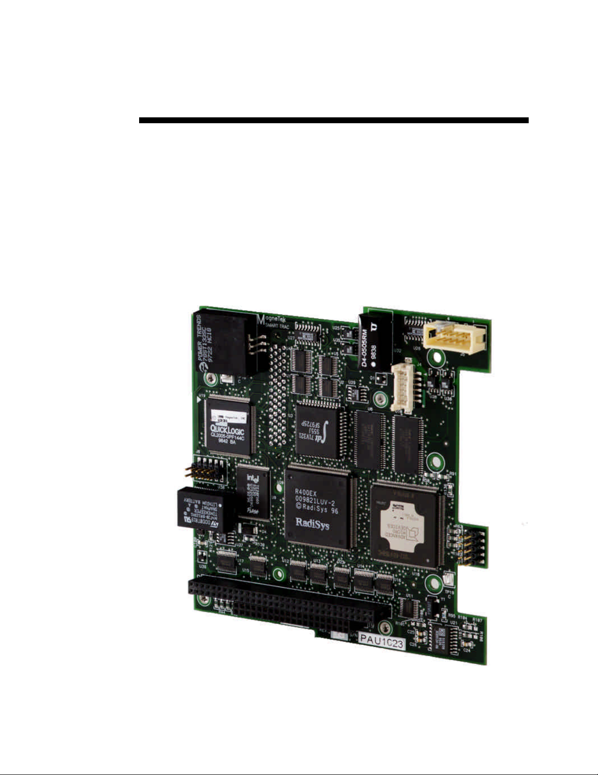
SMART TRAC CPU Card
Contents
Important Safety and Warranty Information 1
Warnings, Cautions and Notes.....................................................................................................................1
General Safety Precautions - Warnings ......................................................................................................2
Important Warranty Information................................................................................................................2
Smart Trac CPU Card 3
General Capabilities......................................................................................................................................3
Specifications .................................................................................................................................................3
Quick Start.....................................................................................................................................................4
Installing the Smart Trac CPU Card 5
Unpacking ......................................................................................................................................................5
Electrostatic Sensitive Discharge (ESD) Procedures ........................................................................5
Unpacking Procedure........................................................................................................................5
Installing the Smart Trac CPU Card...........................................................................................................5
Interrupts and Addresses Used by the Smart Trac CPU Card 9
Configuration.................................................................................................................................................9
Default Interrupts and Base I/O Addresses ................................................................................................9
CPU Card Layout........................................................................................................................................10
Testing Card Installation 13
Booting and Power-Up Self-Test................................................................................................................13
Normal Boot Messages................................................................................................................................13
Troubleshooting Your Smart Trac CPU Card 15
Operating System Status and Error Messages..........................................................................................15
Offset Kernel/Boot Download Errors to 20100 - 20149............................................................................18
Offset I/O Errors from 1 - 59 to 20201 - 20259.........................................................................................19
Offset Trace Errors to 20300 to 20399.......................................................................................................19
Troubleshooting CPU Problems.................................................................................................................19
Battery Low.....................................................................................................................................19
Problems with Other Cards........................................................................................................................20
Corrective Maintenance 21
Replacing the Battery..................................................................................................................................21
Battery Storage............................................................................................................................................22
Proper Battery Disposal..............................................................................................................................22
Technical Manual Contents •• i
Page 4

SMART TRAC CPU Card
Appendix A – Technical Support 23
Getting Help.................................................................................................................................................23
References ....................................................................................................................................................23
Problem Report ...........................................................................................................................................25
Appendix B – Replaceable Parts 27
Replaceable Parts Listing ...........................................................................................................................27
Appendix C – Removing the Smart Trac Card Stack 29
General Procedures.....................................................................................................................................29
Glossary of Terms 33
Index 35
ii •• Contents Technical Manual
Page 5
SMART TRAC CPU Card
Important Safety and Warranty
Information
Warnings, Cautions and Notes
WARNING
A statement of conditions which MUST BE OBSERVED to
prevent personal injury or death.
WARNING - ESD
A statement of conditions which must be observed to prevent
damage to components due to ESD (ElectroStatic Discharge) and
to prevent personal injury or death.
CAUTION
A statement of conditions which must be observed to prevent
undesired equipment faults, Smart Trac AC1 system degradation
and damage to equipment.
IMPORTANT
A statement of conditions which should be observed during Smart Trac AC
DeviceNet setup or operation to ensure dependable service.
NOTE: Notes indicate information that is in addition to a discussion of the topic
in adjoining text. Alternatively, it may limit or restrict the paragraph(s) that
follow(s) to specific models or conditions.
TIP - Tips indicate information that should make a procedure easier or more
efficient.
Technical Manual Important Safety and Warranty Information •• 1
Page 6
SMART TRAC CPU Card
General Safety Precautions Warnings
Important safety information follows. Please read and understand all
precautions listed below before proceeding with the specification, installation,
set-up or operation of your Smart Trac AC1. Failure to follow any of the
following precautions may result in personal injury or death, or damage to the
equipment.
WARNING - ESD
The Control Printed Circuit Board (PCB) employs CMOS
Integrated Circuits that are easily damaged by static electricity.
Use proper ElectroStatic Discharge (ESD) procedures when
handling the Control PCB. See Smart Trac AC1 Technical Manual
for details. Failure to comply may result in damage to equipment
and/or personal injury.
Important Warranty Information.
Do not modify your Smart Trac AC1, its components, or any of the procedures
contained in the technical documentation supplied by MagneTek. Any
modification of this product by the user is not the responsibility of MagneTek
and will void the warranty.
2 •• Important Safety and Warranty Information Technical Manual
Page 7

Smart Trac CPU Card
General Capabilities
The Smart Trac CPU card permits a Smart Trac AC1 to be quickly programmed
for custom applications using IEC-61131-3 languages. These languages include
Relay Ladder Logic (RLL), Sequential Function Charts (SFC), Function Block
(FB) diagrams, Structured Text (ST), Instruction List (IL) and function blocks
written in the C programming language. It also provides for easily expanded
communications and/or extra Input/Output capabilities.
SMART TRAC CPU Card
The card executes user's programs, provides the interface between the digital
operator and the rest of the Smart Trac AC1, and communicates with other
computers for download, upload and monitoring of programs and data. It
connects to cards conforming to the PC/104 Specification. Several cards,
including option cards, may be added to interact with the Smart Trac CPU card
including: the Smart Trac PG card; Smart Trac Ethernet, Smart Trac LAN,
DeviceNet, Genius PCIM, Modbus, Profi-bus communications cards; and the
Smart Trac Multi-I/O card.
All option cards conform to the PC/104 Specification, Version 2.1. They stack
with the Smart Trac CPU card using its PC/104 expansion bus connector. The
Smart Trac CPU conforms to the PC/104 expansion bus.
Specifications
• Intel 486DX2/66 Mhz processor with 4 Megabytes RAM
• PC/104 expansion bus connector
• Executes programs compliant with IEC-61131-3 languages
• Isolated RS-232 Serial port
• 2 Megabytes programmable flash ROM
• 512 bytes Dual-port RAM
• 32 Kilobytes nonvolatile RAM
• Battery-backed real-time clock
• Chart recording buffer of up to 10 Smart Trac AC1 parameters
• On-board self-test runs at boot-up
Technical Manual Smart Trac CPU Card •• 3
Page 8

SMART TRAC CPU Card
Quick Start
1. Power OFF your Smart Trac AC1.
2. Remove all cards in the Smart Trac card stack except for the Inverter
card (bottom most card of the stack). The Smart Trac CPU card is last
to be removed.
3. Install the replacement Smart Trac CPU Card in your Smart Trac AC1
in the position just above the inverter card.
4. Replace all other cards in their proper position in the card stack.
5. Power up your Smart Trac AC1.
6. Set the Smart Trac system clock and any other boot menu parameters
your application may require.
7. Test your Smart Trac system.
4 •• Smart Trac CPU Card Technical Manual
Page 9
SMART TRAC CPU Card
Installing the Smart Trac CPU
Card
Unpacking
Electrostatic
Sensitive Discharge
(ESD) Procedures
Unpacking Procedure
WARNING WARNING -- ESD ESD
Keep electronic circuit boards in Electrostatic Discharge (ESD)
sensitive protective bags when not being handled. Use proper ESD
procedures (including an ESD wrist strap) when handling circuit
boards. Failure to comply may result in damage to equipment.
When working with an electrostatic discharge (ESD) sensitive device, you
should be grounded at all times. The easiest and most common way to provide
this ground is to use an approved ESD wrist strap. The strap is secured to your
wrist with a wire attached to the strap and clipped or taped to the chassis of the
unit being worked on. Any static is dissipated through the wire to ground,
greatly reducing the possibility of damage to the device.
It is a good idea to touch the chassis with your finger before handling any
electrostatic sensitive device. Any static electricity will be discharged to chassis
ground and will not be transferred to the device.
Always store devices (cards, other electronic components) in ESD protective
bags when not being handled.
Remove the protective shipping and packing material from the card. Ensure
contact wedges and other shipping devices have been removed.
Installing the Smart Trac CPU Card
The Smart Trac CPU Card must be positioned above the Smart Trac Inverter
Control card.
NOTE: If replacing a Smart Trac CPU card to an existing Smart Trac card
stack, see Appendix D – "Removing the Smart Trac Card Stack" before
continuing.
Technical Manual Installing the Smart Trac CPU Card •• 5
Page 10
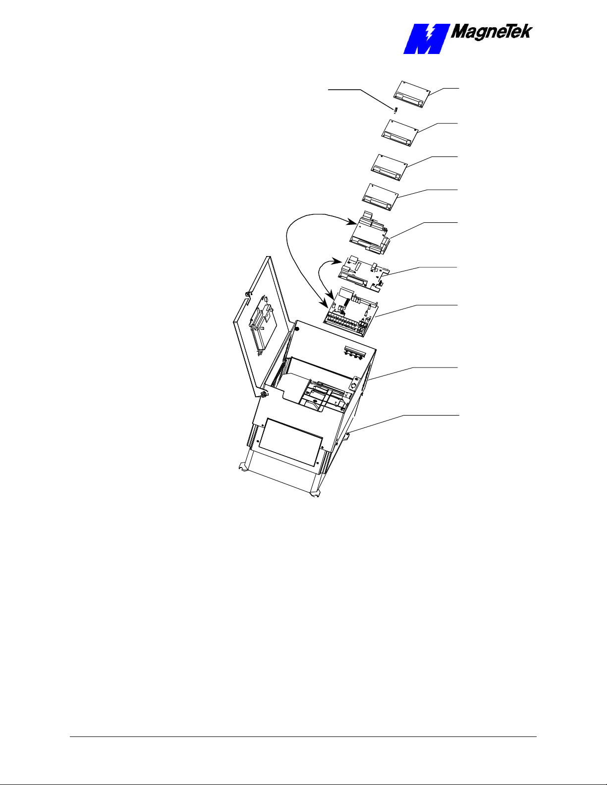
Smart Trac
SMART TRAC CPU Card
Standoffs (4
places on top of
each card)
4CN
Connector
Optional
PC/104
Card
Optional
PC/104
Card
Smart Trac
Ethernet
Card
Smart Trac
PS Card
Smart Trac
PG Card
2CN
Connector
CPU Card
Inverter Control
Card
Adapter
Ring
Main Chassis
Figure 1. Smart Trac CPU Card Stack Position.
1. Install the Smart Trac CPU card. Align the male PC/104 connector pins
on the Smart Trac CPU card with the female PC/104 connector on the
Inverter and the standoff holes with metal standoffs on the Inverter.
When in place, gently but firmly push the Smart Trac CPU card in
place on the Inverter card.
2. Orient the PG card so that the PC/104 connector and the J2 connector
align with the PC/104 connector on the Smart Trac CPU card and the
4CN connector on the Inverter Control board. Be careful to align the
PC/104 connector pins with the receptacle on the Smart Trac CPU card
so the pins don’t bend when the card is pushed into place.
3. Gently but firmly push the Smart Trac PG card onto the Smart Trac
CPU card. Make sure connecting pins are in alignment and J2 mates
with 4CN before pushing the two boards tightly together. Secure the
card using four (4) metal standoffs and one (1) plastic standoff.
6 •• Installing the Smart Trac CPU Card Technical Manual
Page 11

SMART TRAC CPU Card
4. Replace the Smart Trac PG Card and other cards by reversing the
instructions in "Appendix C – Removing the Smart Trac Card Stack".
Technical Manual Installing the Smart Trac CPU Card •• 7
Page 12

Page 13

SMART TRAC CPU Card
Interrupts and Addresses Used
by the Smart Trac CPU Card
Configuration
No configuration switches or jumpers exist on the Smart Trac CPU card. You
simply install the card and connect it as described in "Installing the Smart Trac
CPU Card."
Default Interrupts and Base I/O
Addresses
Interrupt Smart Trac Use Address
IRQ0 System, timer
IRQ1 Systsem, unused
IRQ2 Not available 0x2e0
IRQ3 COM2 Serial Port 0x2f8
IRQ4 COM1 Serial Port - Digital Operator Port 0x3f8
IRQ5 Ethernet card default 0x320
IRQ6 Available for PC/104 option cards
IRQ7 DeviceNet card default 0x250
IRQ8 System, Real-time Clock
IRQ9 ARCNET cascaded IRQ2 default 0x2e0
IRQ10 System, Internal Heartbeat --IRQ11 Smart Trac Genius PCIM default
IRQ12 Available for PC/104 option cards
IRQ13 System, Math coprocessor
IRQ14 Available for PC/104 option cards
IRQ15 Not Available in Smart Trac
Technical Manual Interrupts and Addresses Used by the Smart Trac CPU Card •• 9
Page 14

SMART TRAC CPU Card
Smart Trac CPU Card Layout
J5 Connector
agneTek
M
J4 Connector
Flash ROM
Lithium
Battery
CPU
J7 Connector
(Not Used)
PC/104 Connector
PC/104 Connector
46S03415-
REV. 01 S/N 0000001
Figure 2. Smart Trac CPU Card Layout.
J5 Connector Pinout
The pinout of Smart Trac CPU card connector J5 is shown in the table below.
One end of a ribbon cable plugs into J5 on the CPU card and the other end of the
cable plugs into DB9 connector on the front of the Smart Trac unit. The DB9
Connector, with only 9 pins, has no connection to the J5 pin.
Smart Trac
CPU card
connector
DB9 Pin #
1 1 NC No Connection
2 3 Tx Transmit (from
3 5 Rx Receive (to CPU)
4 7 NC No Connection
5 9 C5ISO Common
6 2 NC No Connection
7 4 CTS Clear to Send (to
8 6 RTS Request to Send
9 8 NC No Connection
- 10 NC No Connection
Smart Trac
Unit
connector J5
Pin #
Signal
Abbreviation
Signal
Description
CPU)
CPU)
(from CPU)
10 •• Interrupts and Addresses Used by the Smart Trac CPU Card Technical Manual
Page 15

Testing Card Installation
Booting and Power-Up Self-Test
Immediately after power-up of the Smart Trac AC1 with the CPU card installed,
the validity of the operating system is checked. The Smart Trac AC1 BIOS
(Basic Input Output System) performs a self-test to determine the integrity of
RAM, flash memory, system timers and interrupts, among other checks. Any
detected faults appear on the Smart Trac AC1 digital operator.
SMART TRAC CPU Card
Next, the system loads any installed drivers. It checks the validity of the user
program before starting its execution.
Once drivers are installed and the user program is validated, the system
performs according to the user program, responding with diagnostics and error
handling as necessary.
NOTE: If communication with the Smart Trac CPU and other cards in the
Smart Trac AC1 are not established within seven (7) seconds of power-up or
after about two (2) seconds without data being transferred, it will shut down.
The LEDs on the digital operator will flash, indicating this lack of
communication.
Normal Boot Messages
When you power-up your Smart Trac AC1, the operating system running within
the CPU displays a series of messages on the Digital Operator.
If MENU key is not pressed at power up, here is what you see:
Technical Manual Testing Card Installation •• 11
Page 16

SMART TRAC CPU Card
MagneTek
Smart Trac
Displayed for 2 seconds
Starting OS
Displayed for 0.25 second
Operating System
Running
For 0.25 second if Digital Operator
Driver installed. Otherwise,
displays continuously.
Press the MENU
Key to begin
Displayed until MENU key
pressed.
Figure 3. Normal Boot Messages.
If you press the Menu key on the Digital Operator within 2 seconds of the start
of the boot process, you will access the Boot Menu, allowing you to configure
various operating parameters. These parameters include TCP/IP Configuration,
Inverter Type, COM1 Configuration, Serial Download from COM1 or Flash
Memory erasure or programming mode, a check of the firmware version, and
Flash ROM access.
NOTE: The second boot message "Starting OS" can be read as an ASCII string,
output from serial port J5.
12 •• Testing Card Installation Technical Manual
Page 17

SMART TRAC CPU Card
Troubleshooting Your Smart
Trac CPU Card
Operating System Status and Error
Messages
Your application program may include programming code to display the
following messages on the Smart Trac AC1 Digital Operator.
These errors are OR'd with 0x80000000 before displaying on the Digital
Operator.
Possible Smart Trac Operating System Status and Error Messages
Hexadecimal
Message
PCODE_SUCCESS 0x00000000
PROG_EXIT 0x00000000
CONTINUE 0x00000001
INVALID_OPCODE 0x00000002 Std. Major Fault -
PSTACK_OVERFLOW 0x00000003 Std. Major Fault -
PSTACK_UNDERFLOW 0x00000004 Std. Major Fault -
PSTACK_CORRUPTED 0x00000005 Std. Major Fault -
BSTACK_UNDERFLOW 0x00000006 Std. Major Fault -
BSTACK_OVERFLOW 0x00000007 Std. Major Fault -
CSTACK_CORRUPTED 0x00000008
OPERAND_UNDERFLOW 0x00000009 Std. Minor Fault -
DIVIDE_BY_ZERO 0x0000000A Std. Minor Fault -
RESULT_UNDERFLOW 0x0000000B Std. Minor Fault -
RESULT_OVERFLOW 0x0000000C Std. Minor Fault -
INVALID_RESULT 0x0000000D Std. Minor Fault -
ADDR_MODE_UNKNOWN 0x0000000E Std. Major Fault -
ADDR_TYPE_MISMATCH 0x0000000F Std. Major Fault -
DATA_TYPE_UNKNOWN 0x00000010 Std. Major Fault -
DATA_TYPE_MISMATCH 0x00000012 Std. Major Fault -
INVALID_DATA_TYPE 0x00000013 Std. Major Fault -
INVALID_ADDRESS 0x00000014 Std. Major Fault -
OPERAND2_INVALID 0x00000015 Std. Major Fault -
OPERAND1_INVALID 0x00000016 Std. Major Fault -
JUMP_OUTOF_BOUNDS 0x00000017 Std. Major Fault -
ADDR_OUTOF_BOUNDS 0x00000018 Std. Major Fault -
UNKNOWN_FLOAT_ERROR 0x00000019 Std. Minor Fault -
FSTACK_OVERFLOW 0x0000001A Std. Minor Fault -
Address
Meaning
Technical Manual Troubleshooting Your Smart Trac CPU Card •• 13
Page 18

SMART TRAC CPU Card
Possible Smart Trac Operating System Status and Error Messages
Hexadecimal
Message
FSTACK_UNDERFLOW 0x0000001B Std. Minor Fault -
INVALID_OPERAND 0x0000001C Std. Major Fault -
NEG_VALUE 0x0000001D Std. Minor Fault -
MALLOC_FAILED 0x0000001E Std. Major Fault -
INVALID_ACTION 0x0000001F Std. Major Fault -
IO_READ_FAILED 0x00000020 Std. Major Fault -
IO_WRITE_FAILED 0x00000021 Std. Major Fault -
CCALL_FAILED 0x00000022 Std. Major Fault -
STRING_OVERRUN 0x00000023 Std. Minor Fault -
NUM_SHIFTBITS_NEG 0x00000024 Std. Minor Fault -
INVALID_COERCION 0x00000025 Std. Major Fault -
INVALID_ADDR_MODE 0x00000026
INVALID_BIT_NUM 0x00000027
INVALID_DATASIZE 0x00000028
BIT_NUM_OUT_OF_RNG 0x00000029
INVALID_C_FUNC_PTR 0x0000002A
INVALID_LOWER_BND 0x0000002B
INVALID_UPPER_BND 0x0000002C
DATE_TIME_INVALID 0x0000002D
MSG_STRLEN_INVALID 0x00004000
USER_TASK_HUNG 0x00007FF8
NO_STARTUP_ROUTINE 0x00007FF9
BREAKPOINT_SET 0x00007FFA
OFFSET_OUT_OF_RNG 0x00007FFB Std. Major Fault -
TASK_OVERRUN 0x00007FFC Std. Major Fault -
TASK_RESTART_FAIL 0x00007FFD Std. Major Fault -
WATCHDOG_TIMEOUT 0x00007FFE Std. Major Fault -
OH_SHTUFF 0x00007FFF Std. Major Fault -
Address Meaning
These following error codes are not OR'ed with 0x80000000.
Hardware Abstraction Layer Error Codes.
Hexadecimal
Message
HAL_SUCCESS 0x0000
HAL_STARTED 0x00020000
HAL_STOPPED 0x00020001
HAL_INVALID_CMD 0x00020002
HAL_NOTASKS 0x00020003
HAL_CREATETASKFAILED 0x00020004
HAL_TOO_MUCHDATA 0x00020005
HAL_NOSTACKMEM 0x00020006
HAL_FORCE_NOTENABLED 0x00020007
HAL_FORCE_ADDRINVALID 0x00020008
HAL_RTLIB_INDEX_ERR 0x00020009 Runtime library index
HAL_INVALID_IOHANDLE 0x00020010 Invalid I/O handle
HAL_CANNOT_SET_FORCED_MEM 0x00020011 Cannot set forced
HAL_IO_LT_BIND_FAILED 0x00020012
HAL_DOWNLOAD_ACTIVE 0x00020013 Download active
HAL_PROG_RUNNING 0x00020014 An application program
HAL_TASK_NOT_FOUND 0x00020015 Cannot find task in ???
HAL_MEM_CORRUPT 0x00020016 Memory corrupt
HAL_NOPROG_LOADED 0x00020017 No program loaded
HAL_START_IO_FAILED 0x00020018 Start of I/O failed
HAL_INVALID_ADDR 0x00020019 Invalid address
HAL_DOWNLOAD_INACTIVE 0x00020020 Download Inactive
Address Meaning
error
memory
is running
14 •• Troubleshooting Your Smart Trac CPU Card Technical Manual
Page 19

SMART TRAC CPU Card
Hardware Abstraction Layer Error Codes.
Hexadecimal
Message
HAL_INVALID_TASKTYPE 0x00020021 Invalid Task Type
HAL_IOINIT_FAILED 0x00020022 I/O Initialization
HAL_TASKINDEX_INVALID 0x00020023 Task index invalid
HAL_ETHERNET_DRV_BAD 0x00020024 Ethernet drive does not
HAL_ETHCFG_OPEN_FAILED 0x00020025 An attempt to open the
HAL_ETHCFG_WRITE_FAILED 0x00020026 An attempt to write the
HAL_NOMEM 0x00020027 No memory found
HAL_THREAD_PRIO_FAILED 0x00020028 Thread priority failed.
HAL_DOWNLOAD_DISABLED 0x00020029 Download of programs
HAL_NODENAME_MISMATCH 0x00020030 The nodename does
HAL_STATIC_STORAGE_OPEN_FAILED 0x00020031
HAL_STATIC_STORAGE_CLEAR_FAILED 0x00020032
HAL_STATIC_STORAGE_WRITE_FAILED 0x00020033
HAL_STATIC_STORAGE_READ_FAILED 0x00020034
HAL_STATIC_STORAGE_CLOSE_FAILED 0x00020035
HAL_STATIC_STORAGE_BAD_FORMAT 0x00020036
HAL_UNABLE_TO_CLEAR_MEM 0x00020037 Not able to clear CPU
HAL_INVALID_SUBCMD 0x00020038 Invalid subcommand.
HAL_BLDNUM_MISMATCH 0x00020039
HAL_STOP_IO_FAILED 0x00020040 An attempt to stop the
HAL_INVALID_NUM_PROGS 0x00020041 The number programs
HAL_DUPLICATE_CONT_TASK 0x00020042
HAL_TOO_MANY_CARDS_PER_TASK 0x00020043 Too many cards per
HAL_STATIC_STORAGE_CHKSUM_INVALID 0x00020044 A checksum test of
HAL_KERNEL_PROGRAM_IN_PROGRESS 0x00020045 A download of the
HAL_INVALID_TASK_PRIORITY 0x00020046
HAL_ADDRESS_OUT_OF_RANGE 0x00020047 A memory or I/O
HAL_KERNEL_DWNLD_ABORTED 0x00020048 A download of the
HAL_NO_RT_EXEC_KEY 0x00020049
HAL_UNABLE_TO_SAVE_RT_EXEC_KEY 0x00020050
HAL_NUM_EXPORT_ENTRIES_MISMATCH 0x00020051
HAL_NUM_IMPORT_ENTRIES_MISMATCH 0x00020052
HAL_DLL_NAME_LENGTH_OVERRUN 0x00020053
HAL_LATEBIND_IO_TOO_FEW_FUNCTIONS 0x00020054
HAL_INVALID_SW_REVISION 0x00020055 Invalid Operating
HAL_INVALID_RT_FUNCTION 0x00020056 A runtime library
HAL_LOAD_LIBRARY_FAILED 0x00020057
Address Meaning
procedure has failed.
pass tests
Ethernet configuration
failed.
Ethernet configuration
failed.
during diagnostics.
and data is disabled.
not match those known
by the Smart Trac
system.
memory.
I/O has failed.
indicated are invalid.
task.
static storage on the
CPU card is invalid.
Kernel is in progress.
address is out of valid
ranges.
kernel has been
aborted.
System Software
Revision
function was attempted
for use but is invalid.
Technical Manual Troubleshooting Your Smart Trac CPU Card •• 15
Page 20

SMART TRAC CPU Card
Hardware Abstraction Layer Error Codes.
Hexadecimal
Message
HAL_DATA_TABLE_PTR_MISMATCH 0x00020058 A pointer within a data
HAL_DATA_TABLE_SIZE_MISMATCH 0x00020059 The sizes of data and
HAL_INVALID_SYNC_TASK 0x00020060
HAL_INVALID_SYNC_CARD 0x00020061
HAL_OPERATION_NOT_SUPPORTED 0x00020062
HAL_NO_ROOM_FOR_SOURCE 0x00020063
HAL_NO_SOURCE_TO_UPLOAD 0x00020064
HAL_UNABLE_TO_SAVE_SOURCE_TO_DISK 0x00020065
HAL_SOURCE_OFFSET_INVALID 0x00020066
HAL_INVALID_TIME_DATE 0x00020067
HAL_NO_ROOM_FOR_DB 0x00020068
HAL_NO_DB_MEMORY 0x00020067
HAL_DB_INVALID_TYPE 0x00020068
HAL_ENGINE_MISMATCH 0x00020069
HAL_SERIAL_CMD_INVALID 0x00020070
HAL_UNABLE_TO_OBTAIN_DATA_MUTEX 0x00020071
HAL_CARD_NOT_FOUND 0x00020072
HAL_ENUM_COMPLETE 0x00020073
HAL_INVALID_DATA_TABLE 0x00020074
HAL_INVALID_SYMTABLE_ADDR 0x00020075
HAL_INVALID_SYMTABLE_SIZE 0x00020076
HAL_ADDRESS_MISMATCH 0x00020077
HAL_IO_PRESCAN_FAILED 0x00020078
Address Meaning
table does not match
any known pointers.
the associated table
are different.
Offset Kernel/Boot Download Errors
to 20100 - 20149
Offset Kernel/Boot Download Errors to 20100 - 20149.
Hexadecimal
Message
HAL_KERNEL_ERR_OFFSET 0x00020100
HAL_NO_KERNEL_DOWNLOAD_IN_PROGR
ESS
HAL_INVALID_KERNEL_CHECKSUM 0x00020101
HAL_INVALID_KERNEL_XFER_TYPE 0x00020102
Address Meaning
0x00020100
Offset I/O Errors from 1 - 59 to 20201
- 20259.
Offset I/O Errors from 1 - 59 to 20201 - 20259
Hexadecimal
Message
HAL_IO_ERR_OFFSET 0x00020200
Address
Meaning
16 •• Troubleshooting Your Smart Trac CPU Card Technical Manual
Page 21

SMART TRAC CPU Card
Offset Trace Errors to 20300 to 20399
Offset Trace Errors to 20300 to 20399
Hexadecimal
Message
HAL_ERR_TRACE_ENABLED. 0x00020300
HAL_ILLEGAL_CONDITION. 0x00020301
HAL_TRACE_PIPE_BROKEN 0x00020302
HAL_TRACE_PIPE_OVERFLOW 0x00020303
HAL_TRACE_PIPE_WRITE_FAILED 0x00020304
HAL_INVALID_TRACE_HANDLE. 0x00020305
HAL_TOO_MANY_TRACE_PARAMS 0x00020306
HAL_TRACE_INVALID_EVENT_INDEX 0x00020307
HAL_TRACE_EVENT_NOT_CONFIGURED 0x00020308
Address Meaning
Troubleshooting CPU Problems
Battery Low
Logic in Non-Volatile RAM (NVRAM) determines battery voltage each 24
hours. If a low voltage condition is detected, a message will appear on the
Digital Operator.
Note: If the voltage is low, it sets a bit register. The bit may be read and
interpreted by an application program, so that when the CPU Card's battery
reaches a low charge state, a message will appear on the Digital Operator.
Problems with Other Cards
Several optional cards may be used with your Smart Trac AC1, all controlled by
the CPU card. To attempt to provide detailed troubleshooting procedures for
each of these in this manual would be impractical.
If you experience problems with network communications or input/output,
isolate the problem to the card level and consult the specific manual that shipped
with the card.
Technical Manual Troubleshooting Your Smart Trac CPU Card •• 17
Page 22

Page 23

Corrective Maintenance
Replacing the Battery
An on-board Lithium battery provides power to NVRAM and maintains the
system time and date. See "Smart Trac CPU Card Layout" for location of the
battery on the CPU Card.
SMART TRAC CPU Card
CAUTIONCAUTION
To avoid draining battery do NOT place SNAPHAT pins in a
conductive foam.
To avoid damaging SNAPHAT sockets do NOT wave solder SOIC.
To replace the battery:
Failure to comply may result in premature battery failure.
1. Power OFF the Smart Trac AC1, lock out and tag "Out of Service."
2. Ensure all parameters held in NVRAM have been recorded. Loss of
battery power or removal of the battery causes NVRAM to lose data
normally retained. These values must be reentered after inserting a new
battery.
3. Remove all cards above the CPU (including PC/104 option cards,
Ethernet card, PS Card, and PG Card) according to "Installing the
Smart Trac CPU Card."
4. Using a chip extractor tool, remove the battery from its socket on the
card.
5. Carefully align pin 1 of the battery (corner of battery with the dot
printed on it) and gently but firmly push into place. A key on the
battery prevents you from installing it with terminals reversed.
6. Replace all cards according card replacement steps in "Installing the
Smart Trac CPU Card."
7. Reenter NVRAM functions (TCP/IP address, Inverter Type, COM1
baud rate, date and time).
Technical Manual Corrective Maintenance •• 19
Page 24

SMART TRAC CPU Card
Battery Storage
Store batteries in a dry place. Storing unpackaged battery cells together could
result in cell shorting and heat build-up.
Proper Battery Disposal
When completely discharged, this type of lithium cell is Non-Hazardous per
USEPA Criteria. Dispose of batteries according to appropriate Local, State and
Federal waste regulations. For unreacted Lithium Metal, see the battery
reference in the Appendix to this manual.
20 •• Corrective Maintenance Technical Manual
Page 25

SMART TRAC CPU Card
Appendix A – Technical Support
Getting Help
Should you need technical assistance with installation or troubleshooting of your
Smart Trac AC1, you can phone our Help Desk at either (800)-541-0939 or
(262)-782-0200. Alternatively, you may copy the Problem Report form, found
on the next page, and fax it to us at (262)-782-3418.
References
MagneTek Drives and
Systems
PC/104 Specification,
Version 2.1
Lithium Batteries Product
Guide
For more information about MagneTek drives
and systems, training programs and contacts,
visit:
http://www.magnetekdrives.com
PC/104 Consortium. An overview and the
specification may be obtained at the web site
address:
http://www.controlled.com/pc104/index.html
For a copy of this publication, contact Rayovac
at 608-275-4735 or visit their web site at:
http://www.rayovac.com
Technical Manual Appendix A – Technical Support •• 21
Page 26

SMART TRAC CPU Card
Problem Report
Name:
Address:
City: State: Zip
Serial Number: Smart Trac CPU Card: 66Mhz 100 Mhz
Occurrence: Frequently Intermittantly Rarely
Nature of Problem:
Conditions when problem occurs:
22 •• Appendix A – Technical Support Technical Manual
Page 27

SMART TRAC CPU Card
Appendix B – Replaceable Parts
Replaceable Parts Listing
Description MagneTek Part
Number
Smart Trac CPU Card option kit 46S03643-0010 1
Standoff, 4.5mm, Hex, Stl, CL ZINC,
15mm, M/F, M3, M3
Standoff, 4.5mm, Hex, Stl, CL ZINC,
14mm, M/F, M3, M3
Battery, Lithium 1
Technical Manual – Smart Trac CPU
Card
Card Extraction Tool (Parvus Corporation
Hardware Tools Kit for Smart Trac
AC1
05P00618-0006 3 each
05P00618-0005 1 each
TM 3415-0010 1
P/N PRV-0760A-01
TBD Option
Qty
CPU assy.
CPU assy.
Technical Manual Appendix B – Replaceable Parts •• 23
Page 28

SMART TRAC CPU Card
THIS PAGE INTENTIONALLY LEFT BLANK
24 •• Appendix B – Replaceable Parts Technical Manual
Page 29

SMART TRAC CPU Card
Appendix C – Removing the
Smart Trac Card Stack
General Procedures
1. Power off the Smart Trac AC1. Disconnect it and tag "Out of Service".
2. Do one of the following:
• Open the cover to the Smart Trac AC1 by rotating the spring-
loaded, captive screw counterclockwise. Use a large screwdriver if
necessary to free the slotted screw.
OR
• Loosen the screws holding down the cover.
3. Disconnect the 12-pin wiring harness from connector J4 at the digital
operator.
4. Using the Phillips head screwdriver, remove the ground strap from the
left inside and the ground strap from the top inside of the Smart Trac
AC1 adapter ring.
5. Disconnect the 9-pin RS-232 cable at connector J5 on the Smart Trac
CPU card.
Technical Manual Appendix C – Removing the Smart Trac Card Stack •• 25
Page 30

chassis
board
SMART TRAC CPU Card
12-pin wiring
harness on
Digital Operator
attached to
connector J4 on
Smart Trac
CPU Card
Digital
Operator
9-pin RS-232
cable
attached here
4mm screws
(4 places)
secure ring
to main
Standoffs (4
places)
secure each
board
Smart Trac
Board Stack
PC/104
9-pin RS-232
cable
connector J5
6. Using a 4.5mm hex head driver, remove four standoffs from the
topmost card.
7. Using the PC/104 extraction tool, remove the topmost card from the
stack.
Position
rectangular
"jacks"
around
edges of
PCBs
Squeeze to lift
cards apart
Figure 4. Using the PC/104 Extraction Tool.
8. Repeat step 8 above until all PC/104 cards have been removed.
9. To remove the Smart Trac PG card:
• Disconnect the 4CN connector on the PG card.
• Using a tubular extraction tool or pliers, squeeze the plastic,
spring-loaded retainer built-in to the long plastic standoff located
at the top of the PG card, just above connector J6.
• Using a PC/104 extraction tool, remove the card.
NOTE: The Smart Trac PG card requires unique handling. Wedge the extracting
tool between the PG card and the CPU card. The area between the terminal strip
on the CPU card and the serial numbered edge of the PG card can be lifted first,
then the opposite side (nearest TB1) on the PG card). Alternate sides until the
card is free of the CPU card.
10. To remove the Smart Trac CPU card:
26 •• Appendix C – Removing the Smart Trac Card Stack Technical Manual
Page 31

SMART TRAC CPU Card
• Disconnect the card at the 2CN connector on the CPU card.
• The CPU card is secured with three plastic standoffs with spring-
loaded clips on the end. Squeeze the top of the standoffs (the clips)
with the special cylindrical removal tool, your fingers or needlenosed pliers and lift the CPU card from the Smart Trac Inverter
Control Card.
You have removed the entire card stack. The inverter card, considered part of
the drive, is in clear view.
Technical Manual Appendix C – Removing the Smart Trac Card Stack •• 27
Page 32

Page 33

Glossary of Terms
SMART TRAC CPU Card
Function Block
IEC-61131-3
languages
Instruction List
PC/104 Specification
Relay Ladder Logic
Sequential Function
Charts
Structured Text
One of three Program Control Unit types. A programming language element,
typically represented by a graphical block, consisting of inputs, outputs, internal
variables, and a set of operations. Function blocks are instantiated and can
contain state information from one invocation of an instantiation to the next.
Part 3 of the international standard on Programmable Controllers, which
specifies Programming Languages, including Relay Ladder Logic (RLL),
Structured Text (ST), Sequential Function Charts (SFC), Function Blocks (FB),
and Instruction Lists (IL).
The IEC 61131-3 Instruction List language for programmable controllers.
Alternatively, a program control unit developed using the Instruction List
language.
An embedded PC bus standard. The standard defines the mechanical size of a
self-stacking bus. Also an IEEE draft standard, called the P996.1 Standard for
Compact Embedded PC Modules, PC/104 Specification, Version 2.1, July 1994,
PC/104 Consortium.
An implementation of the IEC 61131-3 Ladder Diagram language.
The IEC-61131-3 defined Sequential Function Chart language used for
programmable controllers or a program control unit developed using Sequential
Function Chart language.
The Structured Text language specified by IEC 61131-3 used in programmable
controllers. It provides a structured programming environment similar to that in
the computer programming language PASCAL.
Technical Manual Glossary of Terms •• 29
Page 34

SMART TRAC CPU Card
THIS PAGE INTENTIONALLY LEFT BLANK
30 •• Glossary of Terms Technical Manual
Page 35

SMART TRAC CPU Card
I
information, safety 2
Installation 5, 9, 19
Inverter 4–6, 4–5, 12, 19, 27
Index
B
Battery 19
BIOS 11
Booting 11
C
Configuration 9, 12, 15
CPU 25
CPU Card Layout 10, 19
D
Default Interrupts and Base I/O
Addresses 9
L
Layout, CPU Card 10, 19
M
MENU key 11–12
Messages, Normal Boot 11
Messages, Status and Error 13
N
Normal Boot Messages 11
O
Offset I/O Errors 16
Offset Kernel/Boot Download
Errors 16
Offset Trace Errors 17
Optional Parts 23
P
parts
optional 23
PC/104 21
E
Electrostatic Sensitive Discharge 5
Error Codes
Hardware Abstraction Layer 14
Errors
Offset I/O 16
Offset Kernel/Boot Download 16
Offset Trace 17
ESD 5
ESD Procedures 2, 5
extraction tool 26
G
Getting Help 21
ground 5
R
reference 20
Removing 5, 7, 25
Replacing the Battery 19
S
safety 1–2
safety information 2
Self-Test 3, 11
static electricity 2, 5
Status and Error Messages 13
strap
wrist 5
T
H
Hardware Abstraction Layer 14
Help 21
Help Desk 21
Technical Manual Index •• 31
Technical Manual 2
tool, extraction 26
troubleshooting
Help Desk 21
Page 36

SMART TRAC CPU Card
Troubleshooting Your Smart Trac
CPU Card 13
W
warranty 1–2
Warranty 2
wrist strap 5
32 •• Index Technical Manual
Page 37

SMART TRAC CPU Card
Data subject to change without notice. Smart Trac is a trademark of MagneTek, Inc. MicroTrac is a registered trademark of MagneTek, Inc. Microsoft, Windows and Windows NT are registered
trademarks of Microsoft Corporation
MagneTek
Drives and Systems
16555 West Ryerson Road
New Berlin, WI 53151
(800) 541-0939, (262) 782-0200, FAX (262) 782-3418
TM 3415-0010 © 1999-2000 MagneTek, Inc. 1/31/2000
 Loading...