

Page 1

S
S
M
M
A
A
R
R
T
T
T
T
R
R
A
A
Technical Manual
™
™
C
C
A
A
C
C
1
1
Page 2

Page 3

SMART TRAC AC1
Table of Contents
List of Figures..................................................................................................................................iv
List of Tables ...................................................................................................................................iv
Warranty............................................................................................................................................v
Limitation of Liability .......................................................................................................................v
Important Safety and Warranty Information 1-1
Warnings, Cautions and Notes.................................................................................................................1-1
General Safety Precautions - Warnings .................................................................................................. 1-2
Important Warranty Information............................................................................................................ 1-2
Smart Trac AC1 2-1
Overview..................................................................................................................................................... 2-1
General Capabilities......................................................................................................................2-1
Specifications................................................................................................................................ 2-2
Assembling a Smart Trac AC1 3-1
The Contents of Your Shipment............................................................................................................... 3-1
Assembly Procedure.................................................................................................................................. 3-1
Option Cards.............................................................................................................................................. 3-5
Smart Trac PG Card...................................................................................................................... 3-6
Smart Trac PS Card....................................................................................................................... 3-6
Smart Trac Ethernet Card.............................................................................................................. 3-6
Optional PC-104 Compliant Cards................................................................................................ 3-6
Smart Trac AC1 Installation 4-1
Installing Your Smart Trac AC1 ............................................................................................................. 4-2
Storage .......................................................................................................................................... 4-2
Unpacking..................................................................................................................................... 4-2
Locating Your Smart Trac AC1.................................................................................................... 4-2
Making Electrical Connections..................................................................................................... 4-4
Smart Trac Grounding................................................................................................................. 4-10
Connecting Auxiliary Input and Output Power Option Devices................................................. 4-12
Connecting the Control Circuit................................................................................................... 4-12
Terminating Shielded Cable........................................................................................................ 4-16
Connecting Optional Cards......................................................................................................... 4-16
Pre-Power Checklist................................................................................................................................ 4-17
Booting and Power-Up Self-Test............................................................................................................ 4-17
The Boot Menu ........................................................................................................................................ 4-17
TCP/IP Address........................................................................................................................... 4-19
Inverter Type............................................................................................................................... 4-19
COM1 Config ............................................................................................................................. 4-19
Serial Download?........................................................................................................................ 4-20
Firmware Version........................................................................................................................ 4-20
Technical Manual TM 3554-000 •• 0-i
Page 4

SMART TRAC AC1
Flash Access................................................................................................................................ 4-20
Start System?............................................................................................................................... 4-20
Setting the System Time ............................................................................................................. 4-20
Connecting the Vector Controlled Motor.............................................................................................. 4-20
Tune Your Smart Trac AC1................................................................................................................... 4-21
Power On and Preliminary Checks ............................................................................................. 4-21
Tachometer and Motor Rotation Check................................................................................................ 4-24
Recording Settings Using the Programming Menu.............................................................................. 4-27
Auto-Tuning Faults and Corrective Actions......................................................................................... 4-29
Networking the Smart Trac AC1 5-1
Types of Networks for Your Smart Trac AC1........................................................................................ 5-1
PC-based Operation ...................................................................................................................... 5-1
Self-Contained, Control Networks................................................................................................ 5-1
Using Ethernet for PC-based Operation........................................................................................ 5-2
Ethernet Network Architecture ............................................................................................................... 5-4
Linear Bus using 10Base-T.......................................................................................................... 5-4
Star network using 10Base-2 or 10Base-T.................................................................................... 5-5
Ethernet Network Configuration............................................................................................................. 5-7
Addresses and subnet mask........................................................................................................... 5-7
Configuration for PC-Based Operation......................................................................................... 5-7
Configuration for an enterprise-wide LAN................................................................................... 5-8
Verifying Your TCP/IP Configuration........................................................................................ 5-10
Troubleshooting Your Smart Trac AC1 6-1
Reporting of Faults and Errors................................................................................................................ 6-1
Fault Histories............................................................................................................................... 6-1
Resetting Faults............................................................................................................................. 6-2
Clearing Faults.............................................................................................................................. 6-2
Troubleshooting Motor Symptoms.......................................................................................................... 6-2
If the drive/motor will not operate ................................................................................................ 6-3
Troubleshooting For Fault Conditions.................................................................................................... 6-3
Smart Trac AC1 Maintenance 7-1
Preventive Maintenance............................................................................................................................ 7-1
Corrective Maintenance............................................................................................................................ 7-3
Replacing Parts.............................................................................................................................. 7-3
Ordering Parts ............................................................................................................................... 7-6
Appendix A – Dimensions 8-1
Smart Trac AC1 Dimensions.................................................................................................................... 8-1
Mounting Hardware and Hole Dimensions............................................................................................. 8-3
Appendix B – Detailed Specifications 8-5
AC1 Specifications..................................................................................................................................... 8-5
Appendix C - Wiring, Grounding and Installation Practices for Noise Immunity 8-9
Wiring, Grounding and Installation Practices........................................................................................ 8-9
Wiring Requirements for Panel Design/Layout:........................................................................... 8-9
Wire separation groups – STANDARD PRACTICE:................................................................. 8-10
Wiring Requirements for Shop Wiring....................................................................................... 8-11
0-ii •• Technical Manual TM 3554-000
Page 5

SMART TRAC AC1
Wiring Requirements and Recommendations for Field Installation: .......................................... 8-12
Appendix D - Application Parameters 8-15
Application Parameter Form ................................................................................................................. 8-15
Appendix E – Installing System Software 8-21
Installing Boot, Monitor or Operating System Software and Recovery from CPU Failure............. 8-21
Kernel Download........................................................................................................................ 8-21
Appendix F – Technical Support 8-25
Getting Help............................................................................................................................................. 8-25
Problem Report ....................................................................................................................................... 8-26
Training.................................................................................................................................................... 8-27
References ................................................................................................................................................ 8-29
Appendix G – Replaceable Parts 8-33
Replaceable Parts Listing ....................................................................................................................... 8-33
Glossary of Terms 8-35
Index 8-39
Technical Manual TM 3554-000 •• 0-iii
Page 6

SMART TRAC AC1
List of Figures
List of Tables
Figure 1. Smart Trac card assembly showing option cards. ............................. 3-6
Figure 2. Grounding of Three Smart Trac AC1s (top) and Grounding of Smart
Trac AC1 with Vector Controlled Motor (VCM) (bottom).................... 4-11
Figure 3. Simplified Customer Connection Diagram ..................................... 4-14
Figure 4. Shielded Termination...................................................................... 4-16
Figure 5. The Smart Trac AC1 Boot Process. ................................................4-19
Figure 6. A typical local area network used for PC-based operation of Smart
Trac AC1s................................................................................................. 5-4
Figure 7. A Linear Bus topology using 10Base-T............................................ 5-5
Figure 8. A Star topolgy using 10Base-T......................................................... 5-6
Figure 9. The Command Prompt from Windows NT..................................... 5-10
Figure 10. IPCONFIG results......................................................................... 5-10
Figure 11. A successful PING of the computer you are using........................ 5-11
Figure 12. Using thePC/104 card extraction tool..............................................7-4
Figure 13. Removing the Smart Trac Card Stack............................................. 7-5
Figure 14. The Kernel Download – Download Operations dialog box. .........8-22
Figure 15. The Kernel Download – Communications Setup dialog box........8-23
Table 1. Smart Trac AC1 Specifications.......................................................... 2-2
Table 2. Terminal screws, connectors and clamping torque by wire size......... 4-5
Table 3. Wire Sizing for Main Circuit, 230 Volt..............................................4-6
Table 4. Wire Sizing for Main Circuit, 460 Volt..............................................4-7
Table 5. Wire Sizing for Main Circuit 600V (575V)........................................ 4-9
Table 6.Terminal Definitions of the Inverter Control Card............................ 4-15
Table 7. Motor Setup Parameters ................................................................... 4-23
Table 8. Troubleshooting Faults....................................................................... 6-3
Table 9. Smart Trac AC1 Replaceable Parts List............................................. 7-7
0-iv •• Technical Manual TM 3554-000
Page 7

SMART TRAC AC1
Warranty
Standard products manufactured by MagneTek are warranted to be free from
defects in workmanship and material for a period of one year from date of
shipment and any products which are defective in workmanship or material will
be repaired or replaced, at MagneTek’s option, at no charge to the Buyer. Final
determination as to whether a product is actually defective rests with MagneTek.
The obligation of MagneTek hereunder shall be limited solely to repair or
replace, at MagneTek’s discretion, products that fall within the foregoing
limitations, and shall be conditioned upon receipt by MagneTek of written
notice of any alleged defects or deficiency promptly after discovery and within
the warranty period, and in the case of components or units purchased by
MagneTek, the obligations of MagneTek shall not exceed the settlement that
MagneTek is able to obtain from the supplier thereof. No products shall be
returned to MagneTek without its prior consent. Products which MagneTek
consents to have returned shall be shipped prepaid f.o.b. MagneTek’s factory.
MagneTek cannot assume responsibility or accept invoices for unauthorized
repairs to its components, even though defective. The life of the products of
MagneTek depends, to a large extent, upon the usage thereof, and MAGNETEK
MAKES NO WARRANTY AS TO FITNESS OF ITS PRODUCTS FOR THE
SPECIFIC APPLICATIONS BY THE BUYER NOR AS TO PERIOD OF
SERVICE UNLESS MAGNETEK SPECIFICALLY AGREES OTHERWISE
IN WRITING AFTER THE PROPOSED USAGE HAS BEEN MADE
KNOWN TO IT.
THE FOREGOING WARRANTY IS EXCLUSIVE AND IN LIEU OF ALL
OTHER WARRANTIES, EXPRESSED OR IMPLIED, INCLUDING, BUT
NOT LIMITED TO, ANY WARRANTY OF MERCHANTABILITY OR OF
FITNESS FOR A PARTICULAR PURPOSE AND BUYER HEREBY
WAIVES ANY AND ALL CLAIMS THEREFORE.
Limitation of Liability
IN NO EVENT SHALL MAGNETEK BE LIABLE FOR LOSS OF PROFIT,
INDIRECT, CONSEQUENTIAL, OR INCIDENTAL DAMAGES WHETHER
ARISING OUT OF WARRANTY, BREACH OF CONTRACT OR TORT.
Technical Manual TM 3554-000 •• 0-v
Page 8

SMART TRAC AC1
THIS PAGE LEFT INTENTIONALLY BLANK
0-vi •• Technical Manual TM 3554-000
Page 9
SMART TRAC AC1
Important Safety and Warranty
Information
This Chapter will enable you to:
q Be aware of warnings, cautions and notes as they appear
in the documentation.
q Learn about important warranty information.
Warnings, Cautions and Notes
WARNING
A statement of conditions which MUST BE OBSERVED to
prevent personal injury or death.
WARNING - ESD
A statement of conditions which must be observed to prevent
damage to components due to ESD (ElectroStatic Discharge) and
to prevent personal injury or death.
CAUTION
A statement of conditions which must be observed to prevent
undesired equipment faults, Smart Trac AC1 system degradation
and damage to equipment.
IMPORTANT
A statement of conditions which should be observed during Smart Trac AC
setup or operation to ensure dependable service.
Technical Manual TM 3554-000 Important Safety and Warranty Information •• 1-1
Page 10
SMART TRAC AC1
NOTE: Notes indicate information that is in addition to a discussion of the topic
in adjoining text. Alternatively, it may limit or restrict the paragraph(s) that
follow(s) to specific models or conditions.
TIP - Tips indicate information that should make a procedure easier or more
efficient.
General Safety Precautions Warnings
Important safety information follows. Please read and understand all
precautions listed below before proceeding with the specification, installation,
set-up or operation of your Smart Trac AC1. Failure to follow any of the
following precautions may result in personal injury or death, or damage to the
equipment.
WARNING - ESD
The Control Printed Circuit Board (PCB) employs CMOS
Integrated Circuits that are easily damaged by static electricity.
Use proper ElectroStatic Discharge (ESD) procedures when
handling the Control PCB. See Smart Trac AC1 Technical Manual
for details. Failure to comply may result in damage to equipment
and/or personal injury.
Important Warranty Information.
Do not modify your Smart Trac AC1, its components, or any of the procedures
contained in the technical documentation supplied by MagneTek. Any
modification of this product by the user is not the responsibility of MagneTek
and will void the warranty.
1-2 •• Important Safety and Warranty Information Technical Manual TM 3554-000
Page 11

SMART TRAC AC1
WARNINGWARNING
Verify that the rated voltage of the Smart Trac AC1 matches the
voltage of the incoming power.
Always ground the Smart Trac AC1 using ground terminal G. See the
detailed instructions provided in the Smart Trac Technical Manual.
Wiring must be performed only by qualified personnel.
Do not perform a "HIPOT" or withstand voltage test on any part of
the Smart Trac AC1. The AC1 uses semi-conductors and is vulnerable
to high voltage.
Never connect the main circuit output terminals T1, T2 and T3 to the
AC main circuit power supply.
All parameters have been factory set to values commonly used. Do
not change their settings without good reason.
Failure to comply with this warning may result in damage to the
Smart Trac AC1 and connected equipment along with personal injury
and/or death.
WARNING WARNING -- ESD ESD
The Control Printed Circuit Board (PCB) employs CMOS Integrated
Circuits that are easily damaged by static electricity. Use proper
Electrostatic Discharge (ESD) procedures when handling the Control
PCB. Failure to comply may result in damage to equipment and/or
personal injury.
CAUTIONCAUTION
All parameters have been factory set to values commonly used. Do not
change their settings without a full understanding of their impact on
Smart Trac AC1 and machine operation. Failure to comply may result
in damage to equipment and/or personal injury.
Technical Manual TM 3554-000 Important Safety and Warranty Information •• 1-3
Page 12

SMART TRAC AC1
THIS PAGE INTENTIONALLY LEFT BLANK
1-4 •• Important Safety and Warranty Information Technical Manual TM 3554-000
Page 13

Smart Trac AC1
This Chapter will enable you to:
q Describe the capabilities of the Smart Trac AC1
q Become familiar with the ratings and specifications of the
Smart Trac AC1
SMART TRAC AC1
General Capabilities
Overview
The Smart Trac AC1 is a high performance, programmable AC motor drive that
eliminates the need for an external PLC or PC to control a machine or process.
Utilizing the Windows® environment, Smart Trac Workstation™ software allows
the Smart Trac AC1 to be programmed efficiently and easily. Each Smart Trac
AC1 can be programmed to fulfill a specific function and purpose using any of
the five IEC-61131-3 programming languages. IEC-61131-3 programming
languages include Relay Ladder Logic (RLL), Structured Text (ST), Sequential
Function Charts (SFC), Function Blocks (FB) or Instruction Lists (IL).
Commonly used function blocks may be obtained from MagneTek's Program
Library. Consult your local MagneTek representative for details.
Smart Trac AC1 offers many means of communications with other control
devices using either the built-in RS-232 port or any of the optional add-on
communication cards. A MagneTek ARCNET card may be used to
communicate with MicroTrac® LAN systems, providing backward
compatibility with existing MagneTek systems. In addition, the Smart Trac AC1
system supports off-the-shelf Ethernet, DeviceNet, Profibus, SDS, Interbus-S,
Fiber Optic and local I/O cards conforming to PC/104 specifications for form
and fit.
The Smart Trac AC1 provides a sine-coded and pulse width modulated threephase output with adjustable voltage and frequency. This provides for complete
speed and/or torque control of any conventional squirrel cage induction motor.
Automatic stall prevention and voltage boost prevents nuisance tripping during
load or line side transient conditions. The Smart Trac AC1 will not induce any
voltage line notching distortion back to the utility line and will maintain a
displacement power factor of not less than 0.98 throughout its speed range.
Technical Manual TM 3554-000 Smart Trac AC1 •• 2-1
Page 14

SMART TRAC AC1
Specifications
Table 1. Smart Trac AC1 Specifications
Characteristic Specification
Ratings: 0.75 to 100 HP at 230 VAC
1.0 to 1600 HP at 460 VAC
2.0 to 200 HP at 600 VAC
Amperes 3.2 to 1,600 amps, depending on model
Input Power – 208/230V
Class
Output Power-208/230V
Class
Input Power –
380/415/460V Class
Output Power–
380/415/460V Class
Input Power –
575 / 600 V Class
Output Power–
575 / 600 V Class
Overload Capacity 150% for 1 minute
Enclosure Types NEMA 1 Protected Chassis, NEMA 4 , or NEMA 12
Ambient Operating
Temp.
Storage Temperature -20° C to 60° C
Humidity 95% RH non-condensing
Vibration 1G<20Hz, 0.2G 20 to 50 Hz
Location Indoor, protected from corrosive gases and dust
Elevation 3300 ft (1000 M) or less
Voltage: 3 Phase 200/208/220/230 VAC +10%, -15%
Frequency: 50/60 Hz ± 5%
Voltage: 0-230V (proportional to input voltage)
Frequency: 0-400 Hz (V/Hz pattern selectable)
Voltage: 3 Phase 380/400/415/440/460 VAC +10%, -15%
Frequency: 50/60 Hz ± 5%
Voltage: 0-460V (proportional to input voltage)
Frequency: 0-400 Hz (V/Hz pattern selectable)
Voltage: 3 Phase 500/ 575/ 600 VAC ±10%
Frequency: 50/60 Hz ± 5%
Voltage: 0-575V (proportional to input voltage)
Frequency: 0-400 Hz (V/Hz pattern selectable)
0°C to 40° C
2-2 •• Smart Trac AC1 Technical Manual TM 3554-000
Page 15

SMART TRAC AC1
Assembling a Smart Trac AC1
This Chapter will enable you to:
q Understand what is contained within your Smart Trac
AC1
q Learn how to assemble your Smart Trac AC1 from the
components you received.
q Recognize each of the Option cards in your Smart Trac
AC1
The Contents of Your Shipment
Because Smart Trac AC1s are shipped to your specifications, there is wide
variation in the types and numbers of component parts shipped to you. While
some of your components may already be assembled, the assembly procedures
in this chapter assume that you've received the following components :
• Smart Trac AC1 Chassis, Drive and Inverter Card (assembled)
• Cover and Adapter Ring
• Smart Trac CPU Card
• Smart Trac Option Cards (as specified for your configuration)
Assembly Procedure
Use the following procedure for first time installation of your Smart Trac AC1
only!
WARNING WARNING -- ESD ESD
The Smart Trac AC1 electronics are electrostatic sensitive devices.
Follow Electrostatic Discharge (ESD) procedures when handling to
protect components. Failure to follow ESD procedures may result in
damage to the Smart Trac AC1 or its components.
1. Ensure wiring harness at connector 7CN, located at the top of the Smart
Trac Inverter card, is connected to the 7CN connector on the primary
power supply printed circuit board (1PCB). The power supply board is
either a Power PCB (units B034 or less) or a Gate Drive PCB (A064 or
higher number).
Technical Manual TM 3554-000 Assembling a Smart Trac AC1 •• 3-1
Page 16

SMART TRAC AC1
While rotating the Smart Trac CPU card about 45 degrees from its base
should be oriented so the standoff screw hole is on the left and the plate
2. Ensure ground strap E, located at bottom of inverter card, is connected
to the Smart Trac case ground terminal (indicated by the printed ground
symbol .
NOTE: The case ground terminals are the two screw terminals in the lower left
of smaller cases, or placed one on the lower left and one on the lower right sides
of larger cases. You can use either or both terminals to connect ground straps,
depending on the length of the strap or your preference.
3. Connect and tighten all electrical leads to terminal blocks on the Smart
Trac Inverter card to their proper termination, as shown on the specific
connection diagram for your Smart Trac AC1 installation.
4. Remove the Smart Trac CPU card (marked "ST") from its anti-static
bag.
5. Familiarize yourself with the location of the 2CN connector on the
Inverter card. The female half of the black 2CN connector is located on
the Smart Trac Inverter card. The male half is located on the Smart
Trac CPU card.
NOTE: Standoffs used
between the Smart Trac CPU
and Inverter cards are
shorter than other standoffs
6.
position, set the Smart Trac CPU card locking plate into the plastic
locking tab on the Inverter card. Align the holes in the locking plate
with the special, short black plastic standoffs. The metal locking plate
used between all other cards.
is below the plane of the black plastic standoffs. Rotate the card
downward to lock in place.
7. Insert four metal standoffs through four outside holes in the Smart Trac
Inverter card and screw into the four standoffs on the underside of the
card. Tighten standoffs with fingers (torque to about 10 in-lbs).
8. Locate the three plastic standoffs and spring-loaded clips that secure
the Smart Trac CPU card to the Smart Trac Inverter card through holes
in the card.
9. Orient the Smart Trac CPU card with the PC/104 connector at the
bottom. The MagneTek logo, printed on the card, should be at the top.
Slip the Smart Trac CPU card under the wiring harness connector (the
harness is connected to 1CN on the inverter card). Rotate slightly
upward from the left.
10. Align the male and female halves of the 2CN connector and, being
careful not to bend the pins of the 2CN connector, press the Smart Trac
CPU card firmly into place on the Smart Trac Inverter card (1PCB).
You should see and hear the plastic standoffs and spring-loaded clips
snap into place.
NOTE: Depending on the
drive and case size, make
encoder connections before
installing the Smart Trac PG
Card.
11. Install four metal standoffs through four outside holes in the Smart
Trac CPU card and screw into the four standoffs on the underside of
the card. One standoff may be a different color thatn the other three.
This standoff is inserted through the CPU card and into the trhreaded
hole in the metal locking plate. Tighten standoffs with fingers (torque
to about 10 in-lbs).
12. If you purchased the Smart Trac PG card option, install it at as follows.
Otherwise, proceed immediately to step 12.
3-2 •• Assembling a Smart Trac AC1 Technical Manual TM 3554-000
Page 17

SMART TRAC AC1
a. Locate two block pin positions on the female PC/104 connector.
Using a pin or other sharp object, carefully remove two black plugs
from the two blocked pin positions.
b. Orient the Smart Trac PG card so that the PC/104 connector and
the J2 connector (on the solder side of the card) align with the
PC/104 connector on the Smart Trac CPU card and the 4CN
connector on the Inverter Control card. The standoff hole above J6
must slip over the plastic standoff. Be careful to align the PC/104
connector pins with the receptacle on the Smart Trac CPU card so
the pins don't bend when the card is pushed into place.
c. Gently but firmly push the Smart Trac PG card onto the Smart
Trac CPU card. Make sure connecting pins are in alignment and J2
mates with 4CN before pushing the two boards tightly together.
Secure the card using four (4) metal standoffs and one (1) plastic
standoff. Tighten metal standoffs with fingers (torque to about 10
lb-ft).
13. Position the Adapter Ring over the drive chassis, aligning two tabs on
the right side of the ring with slots in the chassis.
14. Secure the Adapter Ring to the chassis using two or four Phillips head
screws, depending on drive case size.
15. Connect the 9-pin RS-232 cable at connector J5 on the Smart Trac CPU
card.
16. If your unit includes a Smart Trac PG card, connect the ground strap
from J11 on the Smart Trac PG card, to the left inside and top inside of
the Adapter Ring.
17. Connect the 12-pin wiring harness from the Digital Operator to
connector J4 on the Smart Trac PS card.
18. Install other option cards per instructions included with each card. See
"Option Cards" below for general information.
19. Close the cover and tighten the screws or single captive screw to secure
the cover.
20. Your Smart Trac AC1 should not be assembled and ready for
connection to a 110V power supply.
Technical Manual TM 3554-000 Assembling a Smart Trac AC1 •• 3-3
Page 18
SMART TRAC AC1
PS Card
Smart Trac
Option Cards
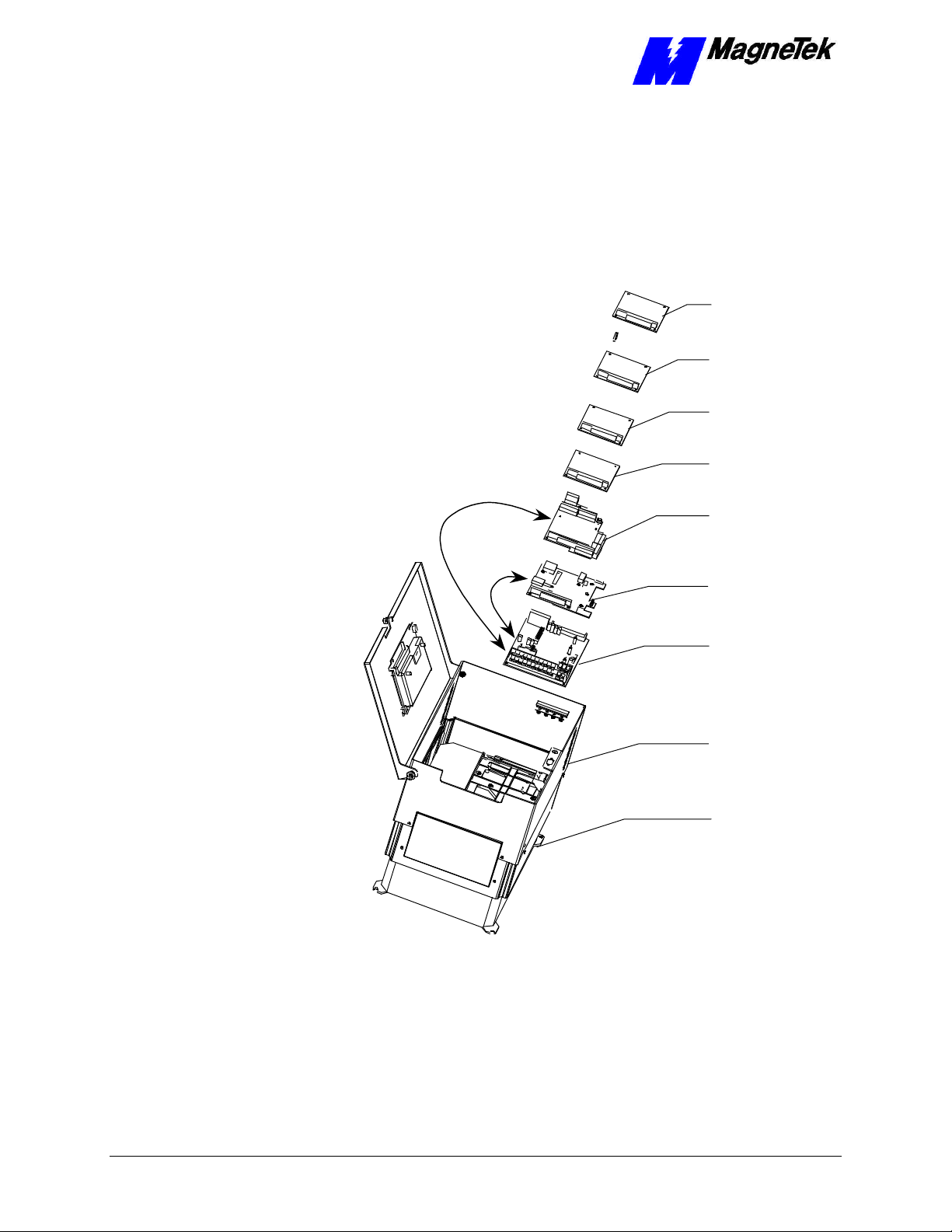
The Smart Trac Inverter Control Card is the first card of the stack. It is the card
on which all others are stacked. The Smart Trac CPU card is mounted on top of
the Smart Trac Inverter and communicates with it via the connector labeled
2CN.
Optional
PC/104
Card
Optional
PC/104
Card
Ethernet
Card
Smart Trac
4CN
Connector
Smart Trac
PG Card
2CN
Connector
Smart Trac
CPU Card
Figure 1. Smart Trac card assembly showing option cards.
Inverter Control
Card
Adapter
Ring
Main Chassis
3-4 •• Assembling a Smart Trac AC1 Technical Manual TM 3554-000
Page 19

SMART TRAC AC1
Smart Trac PG Card
Smart Trac PS Card
Smart Trac Ethernet
Card
Optional PC-104
Compliant Cards
The Smart Trac PG (Pulse Generator) card is installed on top of the Smart Trac
CPU card. It communicates with the Smart Trac Inverter control card via
connector 4CN and the Smart Trac CPU card's PC/104 connector. The Smart
Trac PG card accumulates pulses (A, B and Z) from both master and follower
encoders. It has two analog inputs and can accept two proximity switches. It
includes its own +5V power supply rated at 50 ma. This 50 ma power is
typically ample for applications requiring a load cell.
The Smart Trac PS (Power Supply) card is connected to the Smart Trac PG card
via the PC/104 connector and supplies all the voltages and power to support the
Smart Trac CPU, Smart Trac PG, and all other option cards. If the Smart Trac
PG card is not installed, the Smart Trac PS connects to the Smart Trac CPU.
The Smart Trac Ethernet Card is a PC/104 compliant card included in all Smart
Trac AC1s, providing quick program downloads and uploads and fast, reliable
networking capabilities.
Several additional PC/104 compliant option cards may be stacked on top of the
Smart Trac PG card. Optional cards might include local I/O, ARCNET, Genius,
DeviceNet, Profibus or fiber optic cards for communications and/or additional
system I/O. The Smart Trac ARCNET card allows the Smart Trac AC1 to
communicate with MagneTek Micro Trac drives, making it fully backward
compatible with MagneTek's earlier drive systems. DeviceNet, Profibus and
Fiber Optic cards will support master/slave and peer-to-peer communications.
See the documentation on the individual option cards for further information
Technical Manual TM 3554-000 Assembling a Smart Trac AC1 •• 3-5
Page 20

Page 21

SMART TRAC AC1
Smart Trac AC1 Installation
This Chapter will enable you to:
q Prepare your Smart Trac AC1 for installation
q Determine a physical location for your Smart Trac AC1.
q Make required electrical connections.
q Recommend the proper grounding and shielding for your
Smart Trac AC1.
q Run adequate conduit for the wiring to and from your
Smart Trac AC1.
q Audit your Smart Trac AC1 system using the Pre-power
checklist.
q Become familiar with the Digital Operator
q Start your Smart Trac AC1 for the first time.
q Connect one or more vector-controlled motors.
q Perform an integrated Smart Trac AC1 and motor test.
Technical Manual TM 3554-000 Smart Trac AC1 Installation •• 4-1
Page 22

SMART TRAC AC1
Installing Your Smart Trac AC1
WARNING WARNING -- ESD ESD
Keep electronic circuit boards in Electrostatic Discharge (ESD)
protective bags when not being handled. Use proper ESD
procedures (including an ESD wrist strap) when handling circuit
boards. Failure to comply may result in damage to equipment.
When working with an Electrostatic Discharge (ESD) device, you should be
grounded at all times. The easiest and most common way to provide this ground
is to use an approved ESD wrist strap. The strap is secured to your wrist with a
wire attached to the strap and clipped or taped to the chassis of the unit being
worked on. Any static is dissipated through the wire to ground, greatly reducing
the possibility of damage to the device.
It is a good idea to touch the chassis with your finger before handling any
electrostatic sensitive device. Any static electricity will be discharged to chassis
ground and will not be transferred to the device.
Always store devices (cards, other electronic components) in ESD protective
bags when not being handled.
Storage
Unpacking
Contents Checklist
Locating Your Smart
Trac AC1
If the Smart Trac AC-1 will be stored for a while after receipt, keep the Smart
Trac AC1 in its original packaging material. Store the Smart Trac AC1 in a
controlled environment that meets the following:
q temperature range within –20° C to 60° C
q humidity of less than 95% (no condensation)
Remove the protective shipping and packing material from the equipment.
Ensure contact wedges and other shipping devices have been removed.
You should have received the following with your Smart Trac AC1:
q Smart Trac AC1
q Option card(s) and accessories, if purchased, and option card technical
manuals
q Smart Trac Technical Manual
q Applicable Smart Trac AC-1 Bulletins and Application Notes
To achieve proper performance and normal operating life, your Smart Trac AC1
must be installed in an area where it is protected:
q Excessive heat, direct sunlight, rain or moisture.
q Corrosive gases or liquids.
q Vibration, airborne dust or metallic particles.
4-2 •• Smart Trac AC1 Installation Technical Manual TM 3554-000
Page 23

SMART TRAC AC1
Consider the following when planning the installation and installing your Smart
Trac AC1:
• Always lift your Smart Trac AC1 by its base, never by the front cover.
• Install the Smart Trac AC1 on a flat, non-flammable vertical surface
(wall or panel) using mounting screws specified (See "Smart Trac AC1
Dimensions" for screw specifications).
• Provide a minimum 4.7" (26.1cm) clearance above and below the
Smart Trac AC1. This allows for proper air circulation over the heat
sink fins.
• Provide a minimum 1.2" (3.05cm) clearance on each side of the Smart
Trac AC1.
• Mount your Smart Trac AC1 in a freestanding floor-mount cabinet.
Sufficient clearance must be obtained to permit the door to be opened.
• Add a fan or cooling device as necessary to ensure air entering the
Smart Trac AC1 is below 113° F. (45° C) for protected chassis or
below 104° F. (40° C) for NEMA 1. See "Table 1. Smart Trac AC1
Specifications".
Making Electrical
Connections
Complete wire interconnections per information Table 2 and Table 3, Table 4 or
Table 5 , depending on the voltage of your Smart Trac AC1. Always adhere to
the following:
WARNINGWARNING
Wiring should be performed only by qualified personnel.
Disconnect all power to Smart Trac AC1. Do not remove the front
cover while input power is ON.
Never connect the main circuit output terminals T1, T2 and T3 to
the AC main circuit power supply.
Failure to comply with this warning may result in damage to the
Smart Trac AC1 and connected equipment along with personal
injury and/or death.
• Use 600V vinyl-sheathed wire or equivalent.
• Determine wire size to consider voltage drop of leads.
• Wire size must be suitable for NEC Class I Circuits.
• Use UL approved closed loop connectors or CSA certified ring
connectors sized for the selected wire gauge. Install connectors using
only the connector manufacturer's recommended crimp tool. See Table
2.
• Motor lead length should not exceed 164 feet (50 meters). Motor
wiring should be run in a separate conduit from the power wiring. If
lead length must exceed this distance, reduce the carrier frequency and
consult the motor manufacturer for proper installation procedures.
• Never connect AC main power to drive output terminals T1(U), T2(V),
T3(W).
Technical Manual TM 3554-000 Smart Trac AC1 Installation •• 4-3
Page 24

SMART TRAC AC1
• Never allow wire leads to contact metal surfaces. Short-circuit may
result.
• Never connect power factor correction capacitors or noise filters to
Smart Trac AC1 output.
Table 2. Terminal screws, connectors and clamping torque by wire size
Wire
Size
(AWG)
20 0.50 M3.5 1.25-3.5 7.8 0.9 7.0 0.8
18 0.75 M4 1.25-4 13.0 1.5 10.4 1.2
16 1.25 M4 1.25-4 13.0 1.5 10.4 1.2
14 2
12 3.5
10 5.5
8 8
6 14 M6 14-6 40.9 34.8 4.8 4.1
4 22 M8 22-8 100.0 82.6 11.7 10.7
2 38
1/0 60 M10 60-10 182.6 156.5 21.4 18.4
3/0 80 M10 80-10 182.6 156.5 21.4 18.4
4/0 100
MCM300 150 M12 150-12 313.0 191.3 36.7 23.1
MCM400 200 M12 200-12 313.0 191.3 36.7 23.1
MCM650 325 M12 325-12 313.0 191.3 36.7 23.1
M16 325-16 313.0 191.3 36.7 23.1
Wire
Size
(mm2)
ClosedTerminal
Screw
M4 2-4 13.0 1.5 10.4 1.2
M5 2-5 26.1 20.9 3.1 2.4
M4 3.5-4 13.0 1.5 10.4 1.2
M5 3.5-5 26.1 20.9 3.1 2.4
M4 5.5-4 13.0 1.5 10.4 1.2
M5 5.5-5 26.1 20.9 3.1 2.4
M5 8-5 26.1 20.9 3.1 2.4
M6 8-6 40.9 34.8 4.8 4.1
M8 38-8 100.0 82.6 11.7 10.7
M10 38-10 182.6 156.5 21.4 18.4
M10 100-10 182.6 156.5 21.4 18.4
M12 100-12 313.0 191.3 36.7 23.1
Loop
Connector
Clamping
Torque
Steel,
lb-in
Clamping
Torque
Steel, N-m
Clamping
Torque
Copper,
lb-in
Clamping
Torque
Copper,
lb-in
4-4 •• Smart Trac AC1 Installation Technical Manual TM 3554-000
Page 25

Table 3. Wire Sizing for Main Circuit, 230 Volt
SMART TRAC AC1
Smart Trac AC1 Model No. Terminal Symbol
STAC*A003
STAC*A006
STAC*A011
STAC*A017
STAC*A080
STAC*A130
STAC*A160
STAC*A224
STAC*A300
Wire Sizing for Main Circuit, 230 Volt
L1(R), L2(S), L3(T), , 1, 2, B1, B2, T1(U),
T2(V), T3(W), GND
L1(R), L2(S), L3(T), , 1, 2, B1, B2, T1(U),
T2(V), T3(W), GND
L1(R), L2(S), L3(T), , 1, 2, B1, B2, T1(U),
T2(V), T3(W)
GND
L1(R), L2(S), L3(T), , 1, 2, B1, B2, T1(U),
T2(V), T3(W), GND
L1(R), L2(S), L3(T), , 1, 2, B1, B2, T1(U),
T2(V), T3(W), GND
L1(R), L2(S), L3(T), , 1, 2, B1, B2, T1(U),
T2(V), T3(W)
GND
L1(R), L2(S), L3(T), , 1, 2, 3, T1(U),
T2(V), T3(W)
GND
L1(R), L2(S), L3(T), , 1, 2, 3, T1(U),
T2(V), T3(W)
GND
L1(R), L2(S), L3(T), , 1, 2, 3, T1(U),
T2(V), T3(W)
GND
1(r), 2(s)
L1(R), L2(S), L3(T), ,3, T1(U), T2(V), T3(W)
GND
1(r), 2(s)
L1(R), L2(S), L3(T), ,3, T1(U), T2(V), T3(W)
GND
1(r), 2(s)
L1(R), L2(S), L3(T), , 3, T1(U), T2(V),
T3(W)
GND
1(r), 2(s)
L1(R), L2(S), L3(T), , 3, T1(U), T2(V),
T3(W)
GND
1(r), 2(s)
Terminal
Screw
Wire
Size
(AWG)
Wire
Size
(mm2)
M4 14-10 2-5.5
M4 14-10 2-5.5
M4 14-10 2-5.5 STAC*A008
M4 12-10 3.5-5.5
M4 12-10 3.5-5.5
M4 10 5.5
M5 8 8 STAC*A025, STAC*A033
M5 10-8 5.5-8
M6 4 22 STAC*A049
M6 8 8
M8 3 30 STAC*A064
M6 8 8
M8 3 30
M8 6 14
M4 20-10 0.5-5.5
M10 4/0 100
M8 4 22
M4 20-10 0.5-5.5
M10 1/0 XP 60 X 2P
M8 4 22
M4 20-10 0.5-5.5
M10 1/0 XP 60 X 2P
M8 3 30
M4 20-10 0.5-5.5
M12 4/0 X 2P 100 X
2P
M8 1 50
M4 20-10 0.5-5.5
Technical Manual TM 3554-000 Smart Trac AC1 Installation •• 4-5
Page 26

SMART TRAC AC1
Table 4. Wire Sizing for Main Circuit, 460 Volt
Smart Trac AC1 Model No. Terminal Symbol
STAC*B001
STAC*B011, STAC*B014
STAC*B041
STAC*B052
STAC*B065
STAC*B080
STAC*B096
STAC*B128
Wire Sizing for Main Circuit, 460 Volt
L1(R), L2(S), L3(T), , 1, 2, B1, B2, T1(U),
T2(V), T3(W), GND
L1(R), L2(S), L3(T), , 1, 2, B1, B2, T1(U),
T2(V), T3(W)
GND
L1(R), L2(S), L3(T), , 1, 2, B1, B2, T1(U),
T2(V), T3(W), GND
L1(R), L2(S), L3(T), , 1, 2, B1, B2, T1(U),
T2(V), T3(W)
GND
L1(R), L2(S), L3(T), , 1, 2, B1, B2, T1(U),
T2(V), T3(W)
GND
L1(R), L2(S), L3(T), , 1, 2, 3, T1(U),
T2(V), T3(W)
GND
1(r), 2(s)
L1(R), L2(S), L3(T), , 1, 2, 3, T1(U),
T2(V), T3(W)
GND
1(r), 2(s)
L1(R), L2(S), L3(T), , 1, 2, 3, T1(U),
T2(V), T3(W)
GND
1(r), 2(s)
L1(R), L2(S), L3(T), , 1, 2, 3, T1(U),
T2(V), T3(W)
GND
1(r), 2(s)
L1(R), L2(S), L3(T), , 1, 2, 3, T1(U),
T2(V), T3(W)
GND
1(r), 2(s)
L1(R), L2(S), L3(T), , 3, T1(U), T2(V),
T3(W)
GND
1(r), 2 200 (s200), 2 400 (s400)
L1(R), L2(S), L3(T), , 3, T1(U), T2(V),
T3(W)
GND
Terminal
Screw
Wire
Size
(AWG)
Wire
Size
(mm2)
M4 14-10 2-5.5
M4 14-10 2-5.5 STAC*B003, STAC*B004, STAC*B008
M4 12-10 3.5-5.5
M4 12-10 3.5-5.5
M4 8-6 8-14 STAC*B021
M4 8-6 8-14
M5 8-6 8-14 STAC*B027, STAC*B034
M6 8 8
M6 6 14
M8 8 8
M4 20-10 0.5-5.5
M6 4 22
M8 8 8
M4 20-10 0.5-5.5
M8 4 22
M8 8 8
M4 20-10 0.5-5.5
M8 3 30
M8 6 14
M4 20-10 0.5-5.5
M8 1 50
M8 6 14
M4 20-10 0.5-5.5
M10 4/0 100
M8 4 22
M4 20-10 0.5-5.5
M10 1/0 60 x 2P STAC*B165
M8 4 22
4-6 •• Smart Trac AC1 Installation Technical Manual TM 3554-000
Page 27

Wire Sizing for Main Circuit, 460 Volt
SMART TRAC AC1
Wire
Terminal
Smart Trac AC1 Model No. Terminal Symbol
STAC*B224
STAC*B302
STAC*B302
STAC*B450, STAC*B605
1(r), 2 200 (s200), 2 400 (s400)
L1(R), L2(S), L3(T), , 3, T1(U), T2(V),
T3(W)
GND
1(r), 2 200 (s200), 2 400 (s400)
L1(R), L2(S), L3(T), , 3, T1(U), T2(V),
T3(W)
GND
1(r), 2 200 (s200), 2 400 (s400)
L1(R), L2(S), L3(T), , 3, T1(U), T2(V),
T3(W)
GND
1(r), 2 200 (s200), 2 400 (s400)
L1(R), L2(S), L3(T), , 1, 3, T1(U), T2(V),
T3(W)
GND
1(r), 2 20 0 (s200), 2 400 (s400)
Screw
M4 20-10 0.5-5.5
M10 1/0 x 2P 60 x 2P
M8 3 30
M4 20-10 0.5-5.5
M10 1/0 x 2P 60 x 2P
M8 3 30
M4 20-10 0.5-5.5
M12 4/0 x 2P 100 x 2P
M8 1 50
M4 20-10 0.5-5.5
M16 MCM65
M8 1/0 60
M4 20-10 0.5-5.5
Size
(AWG)
0 x 2P
Wire
Size
(mm2)
325 x 2P
Technical Manual TM 3554-000 Smart Trac AC1 Installation •• 4-7
Page 28

SMART TRAC AC1
Table 5. Wire Sizing for Main Circuit 600V (575V).
Smart Trac AC1 Model No. Terminal Symbol
STAC*C010
STAC*C027, STAC*C032
STAC*C041
STAC*C052
STAC*C062
STAC*C077
STAC*C099
Wire Sizing for Main Circuit, 600 Volt
L1(R), L2(S), L3(T), , 1, 2, B1, B2, T1(U),
T2(V), T3(W)
GND
L1(R), L2(S), L3(T), , 1, 2, B1, B2, T1(U),
T2(V), T3(W)
GND
L1(R), L2(S), L3(T), , 1, 2, B1, B2, T1(U),
T2(V), T3(W)
GND
L1(R), L2(S), L3(T), , 1, 2, B1, B2, T1(U),
T2(V), T3(W)
GND
L1(R), L2(S), L3(T), , 1, 2, B1, B2, T1(U),
T2(V), T3(W),
GND
L1(R), L2(S), L3(T), , 1, 2, B1, B2, T1(U),
T2(V), T3(W)
GND
L1(R), L2(S), L3(T), , 1, B1, B2, T1(U),
T2(V), T3(W)
GND
1(r), 2(s)
L1(R), L2(S), L3(T), , 1, T1(U), T2(V),
T3(W)
GND
1(r), 2(s)
L1(R), L2(S), L3(T), , 1, T1(U), T2(V),
T3(W)
GND
1(r), 2(s)
L1(R), L2(S), L3(T), , 1, T1(U), T2(V),
T3(W)
GND
1(r), 2(s)
L1(R), L2(S), L3(T), , 1, T1(U), T2(V),
T3(W)
GND
1(r), 2(s)
L1(R), L2(S), L3(T), , 1, T1(U), T2(V),
T3(W)
Terminal
Screw
M4
Wire
Size
(AWG)
14-10 2-5.5 STAC*C003, STAC*C004
Wire
Size
(mm2)
12-10 3.5-5.5
M4
14-10 2-5.5 STAC*C006
12-10 3.5-5.5
M4 12-10 3.5-5.5
M4
10 5.5 STAC*C012
12-10 3.5-5.5
M5 STAC*C017
10-6 5.5-14
M6
M5 8-6 8-14 STAC*C022
M6 10-6 5.5-14
M6 8-6 8-14
Ä
10-6 5.5-14
M4 14-10 2-5.5
M8 6-1/0 14-50
* 8-2 8-30
M4 14-10 2-5.5
M8 4-1/0 22-50
* 8-2 8-30
M4 14-10 2-5.5
M8 3-1/0 30-50
* 8-2 8-30
M4 14-10 2-5.5
M8 2-1/0 30-50
* 6-2 22-30
M4 14-10 2-5.5
M8 2/0-1/0 50-60
4-8 •• Smart Trac AC1 Installation Technical Manual TM 3554-000
Page 29

Wire Sizing for Main Circuit, 600 Volt
SMART TRAC AC1
Wire
Terminal
Smart Trac AC1 Model No. Terminal Symbol
STAC*C130
STAC*C172
STAC*C200
* Indicates terminal uses a pressure lug.
GND
1(r), 2(s)
L1(R), L2(S), L3(T), , 1, T1(U), T2(V),
T3(W)
GND
1(r), 2(s)
L1(R), L2(S), L3(T), , 1, T1(U), T2(V),
T3(W)
GND
1(r), 2(s)
L1(R), L2(S), L3(T), , 1, T1(U), T2(V),
T3(W)
GND
1(r), 2 (s)
Screw
* 4-2 22-30
M4 14-10 2-5.5
M10 3/0=300 80-150
* 4-2/0 22-60
M4 14-10 2-5.5
M12 300-400 150-200
* 4-2/0 22-60
M4 14-10 2-5.5
M12 350-400 180-200
* 3-2/0 30-60
M4 14-10 2-5.5
Size
(AWG)
Wire
Size
(mm2)
Smart Trac
Grounding
Your Smart Trac AC1 must be solidly grounded using main circuit ground
terminal GND. Refer to the latest edition of the National Electrical Code (NEC),
Article 250, Grounding, for proper grounding methods, especially ground rod
requirements. Select lead size suitable for size of terminal screw. Make the
length as short as possible.
Never ground the Smart Trac AC1 with the same common as welding machines,
motors, or other large-current electrical equipment. Where several Smart Trac
AC1s are used, ground each directly or daisy chain each to the machine ground
bar or ground rod. Refer to Figure 2. Do not form a loop with the ground
leads.
Technical Manual TM 3554-000 Smart Trac AC1 Installation •• 4-9
Page 30

SMART TRAC AC1
Star
washer
between
cabinet
and bus
wire
Electrical
Cabinet
Copper
Bus
Electrical
Cabinet
Copper
Bus
GROUND
NOT
ACCEPTABLE
ACCEPTABLE
GROUND
NOT
ACCEPTABLE
POLE
Electrical
Cabinet
GROUND
POLES
NOT
ACCEPTABLE
ACCEPTABLE
Figure 2. Grounding of Three Smart Trac AC1s (top) and Grounding of Smart
Trac AC1 with Vector Controlled Motor (VCM) (bottom)
POLE
Connecting Auxiliary
Input and Output
Power Option
Devices
Connecting the
Control Circuit
Proper wiring practices and relative locations within the electrical path, from
line to load, are shown in ." Your application may use some or all of the devices
shown. Disregard items depicted which do not match those in your Smart Trac
AC1 configuration.
WARNINGWARNING
Disconnect all power to Smart Trac AC1. Do not remove the front
cover while input power is ON. Failure to comply may result in
personal injury or death.
Mount all power option devices as close to the Smart Trac AC1 as possible.
Keep electrical connections as short as possible. For Models with base
designations of STAC-A003 through STAC-A064, STACWA003 through
STACWA064, STAC-B001 through STAC-B034, and STACWB001 through
STACWB034, an input or DC reactor should be used.
Basic control circuit (signal) terminations on the Smart Trac AC1 are shown in
the "Simplified Customer Connection Diagram."The use of these terminals,
however, is dependent on the needs of the the application program. Terminal
numbers and their function are listed in the table "Terminal Definitions of the
Inverter Control Card."
4-10 •• Smart Trac AC1 Installation Technical Manual TM 3554-000
Page 31

93
OPTIONAL
SMART TRAC
PC104 Card
(ARCNET,
PCIM,
DeviceNet, etc.)
OPTIONAL
SMART TRAC
ETHERNET
CARD
SMART TRAC AC1
OHM
TERM.
230 VAC
Such as
ARCNET
LAN
33
-15 VDC
Analog Input 1
Fan req'd ST*A080 and
above, ST*B041 and above
Input 1
Input 2
PC104 BUS
Differential
Analog Inputs
A10+
A10-
600MV Input Range
AI1+
AI1AI0+
AI0-
10V Input Range
AI1+
AI1-
COM
COM
+10VDC
-10VDC
Shield, 6 pt.
SMART TRAC
POWER
SUPPLY
Load Cell Power
OPTIONAL
SMART TRAC
PG CARD
SMART TRAC
CPU CARD
INVERTER
CONTROL
CARD
L
N
G
30 Encoder I/O Points
110-115 VAC
or 220 VAC
ENCODER
22
23
Analog Input 2
Analog Input
Open-collector Output
25
Open-collector Output
26
Common, Terms. 25 &
27
26
MOTOR
Inverter
Control
Board
Leads connect to motor
from terminal strip on
drive power supply
Input 3
Input 4
Common for
Terms. 1-8
Input 7
Input 6
Input 5
Input 8
7
8
Figure 3. Simplified Customer Connection Diagram
Technical Manual TM 3554-000 Smart Trac AC1 Installation •• 4-11
Page 32

SMART TRAC AC1
Multifunction Analog Output 2, 0 to +11
POWER CONNECTIONS
1-phase power 90-264 V, to Smart
V to +10V (20K ohms), -10 V to
Analog Input 2, 4-20mA (250
Fault Contact-OPEN, capacity:
Multifunction Analog Output
max), Low=True (ON) when connected to terminal
Terminal Definitions of
the Inverter Control
Card
Term No. Function Term No. Function
1* Multifunction Logic Input 1 23
2* Multifunction Logic Input 2 25
3* Multifunction Logic Input 3 26 Open-collector Output
4* Multifunction Logic Input 4 27 Multifunction Open Collector Common
5* Multifunction Logic Input 5 33
6* Multifunction Logic Input 6
7* Multifunction Logic Input 7 L
8* Multifunction Logic Input 8 N
Multifunction contact output
(N.O.) One of 18 functions
available by setting of
parameter H2-01. Contact
capacity: 250 VAC at 1A or
less; or 30 VDC at 1A or less
9, 10
COM, sequence control input
11
common for terminals 1-6, 0 V L2 3-phase power 230 V/460 V
12 Shield sheath of signal leads L3 3-phase power 230 V/460 V
Typically Speed Reference, but
is multifunction analog input: 0
+10V (20K ohms), Can be
changed to manual by setting
of parameter H3-01.
13
14
ohms) T2 Motor
15 +15 VDC T3 Motor
16 Analog Input 1 B1 Dynamic Braking (option)
Multifunction Analog Input
Common, 0 V for terminals 13
17
thru 16, and 33 B2 Dynamic Braking (option)
Fault Contact-OPEN, capacity:
250 VAC at 1A or less or 30
VDC at 1A or less
18
250 VAC at 1A; or less or 30
19
VDC at 1A or less +2 DC Reactor (option)
Fault Contact-OPEN, capacity:
250 VAC at 1A; or less or 30
20
VDC at 1A or less
Mutlifunction Analog Output 1,
21
0 to +11 V; 2mA maximum
Common for terminals 21 and
22
23, 0 to +11V; 2mA max.
9-pin D
connector Isolated RS-232
* NOTE: Terminals 1-8 source +24 VDC (8MA
11
V; 2mA maximum
Open-collector Output: +48 V, 50 mA
maximum
-15 VDC Control power supply for
frequency settins: 20 mA max
Trac PS
1-phase power 90-264 V, to Smart
Trac PS
L1 3-phase power 230 V/460 V
T1 Motor
+1 DC Reactor (option)
Table 6.Terminal Definitions of the Inverter Control Card
Connections
Lead Length:
Wire Sizes:
4-12 •• Smart Trac AC1 Installation Technical Manual TM 3554-000
Make connections according to the "Simplified Customer Connection Diagram"
with the following notes:
Do not exceed 164 feet (50 meters).
Consider voltage drop when determining size. Consult "Table 3. Wire Sizing for
Main Circuit, 230 Volt" on page 6, "Table 4. Wire Sizing for Main Circuit, 460
Volt" on page 7, "Table 5. Wire Sizing for Main Circuit 600V (575V)." on page
9.
Page 33

SMART TRAC AC1
NOTE: Signal and Control Leads require twisted-pair shielded wire (20-16
AWG [0.5 – 1.25mm2]). Shield sheath terminal 12 requires twisted shielded
or twisted-pair shielded wire (20-14 AWG [0.5 – 2.0mm2]).
Signal Leads:
Control Leads:
Power Leads:
Terminating Shielded
Cable
• Multifunction Logic Inputs to Terminals 1 thru 8 and 11.
• Multifunction Analog Inputs to Terminals 12 thru 17, 33.
• Multifunction Analog Outputs to Terminals 21 thru 23.
• Multifunction Open-collector Outputs to Terminals 25 thru 27.
• Multifunction Contacts to Terminals 9 and 10.
• Fault Contacts to Terminals 18, 19 and 20.
• Single Phase Power 90-264 V to Terminals L and N.
• Three Phase Power 230V/460V to Terminals L1, L2 and L3.
• Motor (Output) to Terminals T1, T2 and T3.
Terminate woven metallic shielded cables at only one end, typically at the
power supply end, as shown "Figure 4. Shielded Termination" on page 16.
When using foil type shields, terminate the drain wire in a similar manner.
Connecting Optional
Cards
Figure 4. Shielded Termination
The Optional Smart Trac PG (Pulse Generator) card, Arcnet card and other
cards are described in separate, specific manuals. See the specific manual for
appropriate connection information.
Pre-Power Checklist
q Verify wires are properly connected and no erroneous grounds exist.
q Ensure all debris is removed from the Smart Trac enclosure and there are no
loose wire clippings.
q Verify cooling fans are free of debris and rotate freely.
q Verify all electrical and mechanical connections for the Smart Trac AC1 are
present and tighten, as necessary
q Verify and test source power is correct for the drive installed.
Technical Manual TM 3554-000 Smart Trac AC1 Installation •• 4-13
Page 34

SMART TRAC AC1
Booting and Power-Up Self-Test
Immediately after power-up of the Smart Trac AC1, the validity of the operating
system is checked. The Smart Trac AC1 BIOS (Basic Input Output System)
performs a self-test to determine the integrity of RAM, flash memory, system
timers and interrupts, among other checks. Any detected faults appear on the
Smart Trac AC1 digital operator.
Next, the system loads any installed drivers. It checks the validity of the user
program before starting its execution.
Once drivers are installed and the user program is validated, the system
performs according to the user program, responding with diagnostics and error
handling as necessary.
NOTE: If communication with the Smart Trac processor and its card stack is
not established within 7 seconds of power up or within 2 seconds of no data
transfers, it will shut down. The LEDs on the digital operator will flash,
indicating this lack of communications.
The Boot Menu
CAUTIONCAUTION
Do not change the Boot Menu without understanding the
implications of your actions or unless instructed to do so by a
MagneTek engineer. The menu does not typically require any
Several functions are available by pressing the MENU key within the first 2
seconds of the boot. Figure 5. The Smart Trac AC1 Boot Process." shows the
boot menu and the functions available.
You may scroll through the menu selections using the Up and Down arrow keys
on the Digital Operator. Pressing ENTER while at any one of the menu
selections causes the submenu to display. Some submenus contain entries you
may scroll through using the Up and Down arrow keys. You may change values
of these entries using procedures for those submenus.
To return to the previous menu level, press ESC.
To stop the boot menu from displaying and resume starting the Operating
System, press ESC until a first level menu appears. Scroll using the up and down
arrow keys until the message appears "Start System?". Press ENTER and the
Operating System should resume loading.
changes. Items which may be changed are: setting the system clock;
TCP/IP address; or checking the firmware version. Failure to comply
may result in damage to your Smart Trac AC1 or other equipment.
NOTE: The message "Starting OS" can be used as output at the J5 (serial)
connector if desired. The message is sent after the initial 2 second timeout as
indicated in the "Smart Trac AC1 Boot Process" flow chart.
4-14 •• Smart Trac AC1 Installation Technical Manual TM 3554-000
Page 35

SMART TRAC AC1
MagneTek
Smart Trac
MENU
TCP/IP Config
Inverter Type
COM1 Config
Serial Download?
If 2 sec
timeout
occurs
ENTER
ENTER
ENTER
ENTER
Starting OS
IP Address
Subnet Mask
Gateway Address
DNS Server Addr
2ms Torq Update
5ms Torq Update
Baud Rate
Load from COM1..
Erase FLASH...
Program FLASH...
TCP/IP Address
Inverter Type
COM1 Config
Firmware Version
Flash Access
Start System?
ENTER
ENTER
ENTER
Operating System
Monitor
Boot Code
Erase this?
User Program
Starting OS
Figure 5. The Smart Trac AC1 Boot Process.
Refer to "Addresses and subnet mask" for information on setting the TCP/IP
address through the Boot Menu.
This function changes the Torque Update parameter from 2 milliseconds to 5
milliseconds. Do not change this function without the approval of an application
engineer.
Using this function enables you to change the baud rate of the RS-232
communications port located on display panel. Normally, this port is only used
to download operating system, monitor and boot programs. It should not
normally be changed.
Technical Manual TM 3554-000 Smart Trac AC1 Installation •• 4-15
Page 36

SMART TRAC AC1
Serial Download?
This function allows loading data through the RS-232 port, erasing flash ROM,
or programming Flash ROM. Do not enter this function without the direction or
approval of an application engineer.
Firmware Version
Flash Access
Start System?
Setting the System
Time
Use this function to check the Operating System, Monitor and Boot Code
program versions stored in your Smart Trac AC1.
This function allows erasing of a user program. Do not enter this function
without the direction or approval of an application engineer.
You must always exit the boot menu through this function. Pressing ENTER
starts the operating system for your Smart Trac AC1.
All events occurring in your Smart Trac AC1 are time-stamped with the system
date and time.
To set the system clock:
1. Load Smart Trac Workstation.
2. Right click a node.
3. Click the Set Date/Time selection. The Set Date/Time dialog box
appears indicating the system date and time.
4. Enter a new date in the format DD/MM/YY and time in the format
hh:mm:ss AM/PM. The dialog box indicates the new date and time.
5. Click OK to continue.
Connecting the Vector Controlled
Motor
For best control of
torque or speed
linearity and response
For control in speed
mode or use with
standard motor voltage
ratings
Most MagneTek Vector Controlled Motors (VCMs) may be configured for
either 380V/460V or 190V/230V operation. VMB motors may be configured for
190V or 230V, 380V or 460V. VMC motors may be configure for 230V or
460V. Your application will determine which configuration to use:
To control torque or speed when 150% peak torque is required at a base speed of
90-100%, with 100% torque at 0 RPM, use a low voltage winding – 190V or
380 V motor tap selection mon VMB motor.
Use a high voltage winding, 230V or 460V, when:
• replacing an existing 460V/230V NEMA design B motor with encoder
feedback.
• for speed control when torque limit adjustment is required.
• in high starting torque situations.
Tune Your Smart Trac AC1
Your Smart Trac AC1 does not typically require tuning. Tuning of your Smart
Trac AC1 should be done either by a qualified MagneTek Field Service
Engineer or according to recommended procedures.
4-16 •• Smart Trac AC1 Installation Technical Manual TM 3554-000
Page 37

SMART TRAC AC1
Power On and
Preliminary Checks
1. Verify that the tachometer and motor are rotating properly before
proceeding. Refer to the table "Flux Vector Control Tachometer and
Motor Rotation Check."
2. Make sure that the motor is disconnected from the load. To assure
safety, disconnect the coupling or belt which connects the motor with
the machine so that motor opertion is isolated before testing operations
begin.
3. Power down the Smart Trac AC1. Do not proceed until the CHARGE
light goes OFF.
4. Remove the Digital Operator from the Display Panel and carefully
disconnect the ribbon cable or wiring harness (attached to the Digital
Operator) from its normal location at connector J4 on the CPU card.
5. Disconnect power leads to the Smart Trac CPU at locations L and N.
6. Connect the Digital Operator to connector 1CN on the Smart Trac
Inverter control card PCB.
WARNINGWARNING
Make sure the motor is disconnected from the load before proceeding.
Failure to comply may result in personal injury or death.
7. Power up the Smart Trac AC1.
WARNINGWARNING
Any motor connected to the Smart Trac AC1 will move when autotuning is executed. Take proper precautions. Failure to comply may
result in personal injury or death.
CAUTIONCAUTION
Motor should be disconnected from its load before executing the autotuning routine. Failure to comply may result in damage to the Smart
Trac AC1 and/or other equipment.
NOTE: If the motor cannot be disconnected from the load, or if Auto-Tuning
fails, motor parameters should be entered manually.
8. Enter the motor nameplate values needed to perform Auto-Tuning.
9. Press , then three (3) times. The Smart Trac Main Menu Auto-Tuning will appear.
** Main Menu **
Auto-Tuning
10. Press twice. The message "Rated Voltage" appears.
Technical Manual TM 3554-000 Smart Trac AC1 Installation •• 4-17
Page 38

SMART TRAC AC1
Rated Voltage
400.0 VAC
11. Set the correct Nameplate voltage of the motor, using the and
keys to scroll and the key to move one decimal point to
the right.
Rated Voltage
460.0 VAC
12. Press to store the value in memory. The message "Entry
Accepted" will appear briefly, followed by a return to the previous
"Rated Voltage" message.
Entry Accepted
Rated Voltage
400.0 VAC
13. Enter the current and the rest of the parameters following a similar
procedure to that of the motor nameplate voltage.
14. When all of the parameters are entered, execute Auto-Tuning:
15. Press the . The message "Tuning Ready?" will appear.
Tuning Ready?
Press RUN key
16. Press . The drive will first output current to the motor, then run
the motor at a high speed. During tuning, the following message will
appear.
Tune proceeding
XX Hz X.XX A
• If no problems are encountered., the following message will
appear:
Tune Successful
• If a problem occurs during Auto-Tuning execution, the "Tune
Aborted" message appears with a reason listed. See "Auto-Tuning
Faults and Corrective Actions".
Tune Aborted
"Reason"
17. If successful, record the settings for parameters E2-01 to E2-09. You
use the Programming Menu (see "Checking Motor Parameters").
18. Remove power from the Smart Trac AC1. Wait until the CHARGE
light goes out.
4-18 •• Smart Trac AC1 Installation Technical Manual TM 3554-000
Page 39

SMART TRAC AC1
19. Disconnect the ribbon cable or wiring harness attached to the Digital
Operator from connector PCB 1CN.
20. Connect the Digital Operator to its normal location on connector J4 on
the Smart Trac CPU card.
21. Power up the drive.
22. Load parameters as follows:
Table 7. Motor Setup Parameters
Numeric
Para-
meter Description
Parameter
Number
Displayed
Description
E2-01 Motor rated current 48 RATED MOTOR
AMPS
E2-02 Motor rated slip 47 MOTOR RATED
SLIP
E2-03 Motor no-load current 49 MTR NO LOAD
AMPS
E2-04 Number of motor poles 50 MOTOR POLES
E2-05 Motor line-to-line
51 MTR TERM RES.
resistance
E2-06 Motor leakage inductance 52 MTR LEAKAGE
IND.
E2-07 Motor iron core saturation
53 MTR SAT COEF 1
coefficient 1
E2-08 Motor iron core saturation
54 MTR SAT COEF 2
coefficient 2
E2-09 Motor mechanical loss 55 MTR MECH LOSS
Technical Manual TM 3554-000 Smart Trac AC1 Installation •• 4-19
Page 40

SMART TRAC AC1
Advanced Level
Description Key Sequence
Apply input power to the
drive.
Set the control method of
the drive to Flux Vector
(A1-02 to 3) or to other
control method.
Tachometer and Motor Rotation
Check
Flux Vector Control Tachometer and Motor Rotation Check
Digital Operator
Press , then
Press , then twice
Press ,
Display
** Main Menu **
Initialize
Control Method
Open Loop Vector
A1-02= 3
Flux Vector
Set parameter access
level to Advanced. This
allows all parameters to
be viewed and modified.
then set drive to Flux Vector using:
Write values to memory by pressing
Press , then
Press , then
Press ,
then set drive to Advanced using:
Write value to memory by pressing:
Entry Accepted
briefly, then
Control Method
Flux-Vector
** Main Menu **
Initialize
Access Level
Quick Start
A1-01= 4
** Main Menu **
Initialize
Set PG Pulses/Rev to the
correct value. (NOTE:
For a MagneTek vector
motor, the correct value is
Press , then twice.
** Main Menu **
Programming
1024.)
4-20 •• Smart Trac AC1 Installation Technical Manual TM 3554-000
Page 41

Flux Vector Control Tachometer and Motor Rotation Check
U1-05=- 1.47 Hz
Description Key Sequence
Press , then 4 times
Press 3 times
Set the correct PPR, using:
Write value to memory by pressing:
SMART TRAC AC1
Digital Operator
Display
Group F
Options
PG Pulses/Rev
01024
** Main Menu **
Initialize
Entry Accepted
briefly, then
PG Pulses/Rev
F1-01= 1024
Display motor speed
Rotate the motor shaft
counter-clockwise by
hand (as viewed from the
load end of the motor).
As the shaft is turned
counter-clockwise, a low
positive speed should be
indicated
As the shaft is turned
clockwise, a low negative
speed should be
indicated.
If the speed doesn't
change when the motor
shaft is rotated, check
encoder wiring and
connections. The pulses
from the encoder can also
be checked.
If the polarity is wrong,
switch channels on the
input to the PG card.
Press , then , then
Press , then 4 times
Function U1
Monitor
Motor Speed
U1-05= 0.00 Hz
Motor Speed
U1-05- 2.38 Hz
Motor Speed
Technical Manual TM 3554-000 Smart Trac AC1 Installation •• 4-21
Page 42

SMART TRAC AC1
Description Key Sequence
Check the motor rotation
using the JOG function.
NOTE: The frequency
reference fro this
operation comes from
D1-09 and is factory set
to 6 Hz.
If either or both of the SEQ and REF lights are ON,
The motor should ramp
up to speed, and rotation
should be counterclockwise if the FWD
light is ON. Rotation
should be clockwise if the
REV light is ON. If the
motor does not accelerate
smoothly or oscillates,
reverse any two motor
leads, then repeat the
motor rotation check.
Run the Auto-Tuning
routine:
Flux Vector Control Tachometer and Motor Rotation Check
Digital Operator
Press , then
press
WARNING WARNING The next key-press will
cause the motor to move: take appropriate precautions.
RUN light will
Press and hold
Release
WARNING WARNING
The motor will move when auto-tuning is executed! Take
proper precautions!
illuminate
Display
Frequency Ref
U1-01=0.00 Hz
Frequency Ref
U1-01- 6.00 Hz
CAUTIONCAUTION
The motor should be disconnected from the load before
executing auto-tuning.
NOTE: If the motor
cannot be disconnected
from the load, or if AutoTuning fails, motor
parameters should be
entered manually. (See
manual procedures in this
chapter).
Go to step 8 of the AutoTuning procedure
(above).
4-22 •• Smart Trac AC1 Installation Technical Manual TM 3554-000
Page 43

Recording Settings Using the
Motor Rated FLA
Motor Rated FLA
Programming Menu
Recording Settings Using the Programming Menu
Description Key Sequence
Get to ** Main Menu **
Programming
Enter the motor rated full
load amps (E2-01). This
value can be obtained
from the motor nameplate
(motor full load amps).
Set Full Load Amps (FLA) using:
Press , then twice
Press , then 3 times
Press twice
Write value to memory by pressing
SMART TRAC AC1
Digital Operator
Display
** Main Menu **
Initialize
Group E
Motor
001.00 A
Motor Rated FLA
001.20 A
Entry Accepted
Enter the motor rated slip
(E2-02). This value can
be calculated using the
following formula:
E2-02=
((Ns-Nr)/Ns)*60*.7
Nr=nameplate rated
speed
Ns=synchronous speed
Ns=fR *120 / # of motor
poles
Press , then
Set motor rated slip using:
briefly, then
E2-01= 1.20 A
Motor Rated Slip
02.90 Hz
Motor Rated Slip
1.08 Hz
Technical Manual TM 3554-000 Smart Trac AC1 Installation •• 4-23
Page 44

SMART TRAC AC1
Motor Rated Slip
No-Load Current
Number of Poles
Number of Poles
Description Key Sequence
Enter the motor no-load
current (E2-03). This
value can sometimes be
obtained from the motor
nameplate. If it is
unavailable, use the
following formula to
calculate it:
1-5 HP: I
5-15 HP: I
>15 HP: I
Set motor no load current using: :
NLA=IFLA
NLA=IFLA
NLA=IFLA
Recording Settings Using the Programming Menu
Write value to memory by pressing
Press , then
*.50
* .40
* .30
Digital Operator
Display
Entry Accepted
briefly, then
E2-02= 1.08 Hz
No-Load Current
000.60 A
No-Load Current
000.32 A
Write value to memory by pressing
Enter number of motor
poles (E2-04).
Press , then
(Assuming an fR of 50 or
60 Hz)
Motor RPM # Poles
2400-3600 2
1300-1800 4
900-1200 6
660-900 8
NOTE: This step is not
required for Open Loop
Vector Control method
(A1-02=0).
Set number of motor poles using: :
Entry Accepted
briefly, then
E2-03= 0.32 A
Entry Accepted
briefly, then
04
04
4-24 •• Smart Trac AC1 Installation Technical Manual TM 3554-000
Page 45

Recording Settings Using the Programming Menu
Number of Poles
Description Key Sequence
Write value to memory by pressing
Parameters E2-05 to E209: (see table)
Auto-Tuning Faults and Corrective
Actions
SMART TRAC AC1
Digital Operator
Display
Entry Accepted
briefly, then
E2-04= 4
Digital Operator Display Description Corrective Action
Tune aborted-Data Invalid Motor data is not correct. Check the motor data
Tune aborted-Resistance Line-to-line resistance not
Tune aborted-No-Load
Current
Tune aborted-Sat Coef 1 Iron core saturation
Tune aborted-Sat Coef 2 Iron core saturation
Tune aborted-Rated slip Rated slip not within
Tune aborted-Accelerate Motor did not accelerate in
Tune aborted-PG Direction Encoder phasing opposite
Auto-Tuning Faults and Corrective Actions
entered.
Check the drive and motor
capacities.
within tolerance.
No-load current
(magnetizing current) not
within tolerance.
Check the motor data
coefficient 1 not within
tolerance.
coefficient 2 not within
tolerance.
tolerance.
the specified time.
that of motor phasing.
entered.
Check the motor wiring.
Increase acceleration time
(parameter C1-01).
Increase torque limit values
(parameter L7_01, -02) if
they are reduced from
factory settings.
Swap two motor leads.
OR
Swap channels on the input
to the PG card
Technical Manual TM 3554-000 Smart Trac AC1 Installation •• 4-25
Page 46

SMART TRAC AC1
Auto-Tuning Faults and Corrective Actions
Digital Operator Display Description Corrective Action
Tune aborted-Motor Speed Torque reference exceeded
Tune aborted-Over Load
(Displayed after completion
of tuning)
Tune aborted-Minor Fault:
XXX
Tune aborted-PG Circuit PG cable wires are
100% during auto-tuning.
Torque reference exceeded
20% during auto-tuning
A minor drive fault occurred. Check for specific minor
disconnected.
Uncouple motor from load.
Increase acceleration time
(C1-01).
Check input data, especially
the encoder PPR
(parameter F1-01).
Uncouple motor from load.
Increase acceleration time
(C1-01)
Check input data, especially
the encoder PPR (F1-01).
Power Conversion Unit fault
indicated by "XXX." (See
"Smart Trac Fault Codes
Technical Manual."
Pulse generator is
disconnected from the PG
card. Check PG wiring.
4-26 •• Smart Trac AC1 Installation Technical Manual TM 3554-000
Page 47

SMART TRAC AC1
Networking the Smart Trac AC1
Types of Networks for Your Smart
Trac AC1
Several methods exist to network your Smart Trac AC1: Arcnet, Ethernet,
Profibus, DeviceNet, and others. The methods you choose depend on whether
you will have a "self-contained " network or you will interface to an enterprisewide LAN. Below are a few guidelines to help you choose which method or
combination is right for your application. More than one type of network card
may be stacked in the Smart Trac AC1.
PC-based Operation
Self-Contained,
Control Networks
ARCNET
A typical use of Ethernet involves the addition of an Ethernet card in the stack to
provide a fast, reliable, PC-based interface to the Smart Trac AC1. As an
alternative to a serial RS-232 connection, an Ethernet card may be used for high
speed monitoring, program uploading and downloading, and running
diagnostics. A TCP/IP address is assigned to the ethernet card, as is true of all
ethernet cards running the TCP/IP protocol. However, any valid and unique
TCP/IP address may be assigned, if the device will not interface to a corporate
network.
Most industrial drive networks are self-contained, communicating with each
other to control sections of a specific machine. They do not necessarily interface
with the Internet or a corporate local area network (LAN). ARCNET, Profibus,
DeviceNet, Modbus and Ethernet may be used in self-contained networks.
Ethernet would provide for PC-based operation of Smart Trac AC1s attached to
the network.
Arcnet, or Attached Resource Computer Network, was developed by Datapoint
Corporation. A relatively simple, inexpensive and reliable LAN, it uses token
passing in a star or bus topology to transmit data at up to 2.5 Mbps. Many PLCs
are networked using this networking method. Choose Arcnet if your application
requires multiple Smart Trac AC1s to be coordinated.
RG-62 coaxial cable should be used to connect devices in an Arcnet network.
Up to 255 nodes may be configured using UTP or coaxial cable and hubs.
• The IRQ, I/O port address and node ID of each arcnet node must be set
manually. Because of the way Arcnet initializes stations when the LAN
is first activated, it is important to locate devices with sequential
physical addresses located close to one another.
Technical Manual TM 3554-000 Networking the Smart Trac AC1 •• 5-1
Page 48

SMART TRAC AC1
• Maximum segment lengths are: with a star network and coaxial cable -
2,000 feet; with a bus network and coaxial cable – 1,000 feet; with UTP
cable – 400 feet; with fiber-optic cable – 11,500 feet.
Each end of the network cable must be terminated with a 93 ohm plug, available
from MagneTek (see "Replaceable Parts List").For further details about Arcnet,
reference ARCNET Local Area Network Standard, ATA/ANSI 878.1, ARCNET
Trade Association, 1992.
Profibus - DP
DeviceNet
Modbus
Using Ethernet for
PC-based Operation
Profibus – DP(Decentralized Periphery) provides open, standard, inter-operable
and fully transparent networking between field devices (i.e. Smart Trac AC1s)
and the controlling computers, PLCs and/or DCSs. It supports network speeds of
9600 bps to 12 Mbps over shielded, twisted 2-wire line. Data may be transferred
in 1 byte to 244 byte messages at distances up to 1200 meters. It permits a
maximum of 125 nodes.
DeviceNet is a simple, economical, networking solution to connect industrial
devices (i.e. limit switches, smart motor controllers, operator interfaces, and
variable frequency drives). Programmable controllers and computers may also
be networked using DeviceNet.
It supports network speeds of 125Kpbs, 250 Kbps and 500 Kbps. DeviceNet
cabling consists of a 5-wire cable containing a twisted pair for data
communications, a second twisted pair for network 24 VDC power, and a shield.
It permits a maximum of 64 nodes. Speed is slow, but throughput is high.
Modbus is an industrial communications network that operates via RS-232, RS485 or RS-722 that utilizes the PLC or PC as Master and a Smart Trac AC1 as
Slave. It is an open network and often uses serial port communications at speeds
of 9600 bps to 19,200 bps. Using RS-232, it serves as a point to point (2-device)
network. Using RS-485, it permits a maximum of 31 Smart Trac AC1 nodes.
The most common use of ethernet cards with Smart Trac AC1 will be to permit
a faster, PC-based connection for monitoring the drive, program uploading to
the drive, downloading from the drive, and running diagnostics.
Ethernet generally transmits data at 10 Mbps to 100 Mbps. It was developed by
Intel, Digital (now Compaq), and Xerox as an “open” network standard,
meaning it can network computers using several operating system platforms.
Most types of Ethernet cards, compliant with the PC/104 footprint and Ethernet
standard 802.3, may be installed in your Smart Trac AC1 to provide the
interface for PC-based operation. Check with your MagneTek representative for
a list of Ethernet cards supported by MagneTek. Each Smart Trac is supplied
with one Ethernet card.
To set up an ethernet network, you will need the following:
• a laptop and/or desktop computer on which to run Smart Trac
Workstation.
• ethernet cabling to connect the various devices on the network.
• one or more Smart Trac AC1s.
• a hub, if connecting more than two devices on the network.
A typical PC-based network for operation of Smart Trac AC1s is depicted in
Figure 6.
5-2 •• Networking the Smart Trac AC1 Technical Manual TM 3554-000
Page 49

Laptop computer
Cat-5 Twisted Pair
Ethernet Cable
Cat-5 Twisted Pair
Ethernet Cable
SMART TRAC AC1
SMART
TRAC
AC 1
Laser printer
IBM Compatible
Cat-5 Twisted Pair
Ethernet Cable
Hub
Cat-5 Twisted Pair
Ethernet Cable
Cat-5 Twisted Pair
Ethernet Cable
Cat-5 Twisted Pair
Ethernet Cable
SMART
TRAC
AC 1
Figure 6. A typical local area network used for PC-based operation of Smart
Trac AC1s.
Ethernet Hub
An ethernet hub is required if connecting more than two devices (more than one
Smart Trac AC1 and one computer). If only connecting a single Smart Trac with
a single computer, you need only a special "crossover" or "uplink" Ethernet
cable. (Contact your MagneTek representative for cable information).
Ethernet cabling
SMART
TRAC
AC 1
Two Ethernet cabling standards are commonly used with Smart Trac AC1
systems, each intended for different purposes:
• 10Base-T (Twisted-pair Ethernet) – The most widely used ethernet
cabling, it supports network speeds of 100Mbps. Uses 22- or 26-AWG
UTP cabling to transmit baseband signals on maximum 100-meter
segments. RJ-45 jacks connect separate cables between device and hub.
Each device must be at least 2 feet apart and no more than 328 feet
from the hub. Bridges or routers may be used to accommodate a larger
network. There is no limit on network length. It permits a maximum of
1,024 segments and 1,024 nodes. See IEEE standard 802.3i.
• 10Base-2 (Thin Ethernet) – Supports network speeds of 10Mbps. Uses
RG-58 coaxial cable with "T"-shaped connectors to transmit baseband
signals on 200-meter segments. Total network length can be 925
meters. One end of each linear bus cable must be terminated using a 50
ohm resistor. Transceivers reside on the NIC at each connection of the
trunk cable to a device, simplifying connections. The cable, thinner
than 10Base-5, is more flexible for easier handling. See IEEE standard
802.3a.
Technical Manual TM 3554-000 Networking the Smart Trac AC1 •• 5-3
Page 50

SMART TRAC AC1
Ethernet Network Architecture
Linear Bus using
10Base-T
10BASE-T wall plate
Laptop computer
BNC, or "T"-shaped connectors are used to connect network devices to a coaxial
trunk cable in a linear bus topology. The bus is tied to ground, often at a wall
plate. The other end of the trunk cable (bus) must be terminated with a 50-ohm
resistor. Without termination, broadcast signals bounce back across the network,
causing contention. This, combined with the fact that each device on a linear bus
must wait its turn to broadcast information across the network, results in
decreased performance compared with a star topology, for example. Also, a
linear bus network is more difficult to troubleshoot because all devices are on a
single trunk cable.
A linear bus network is easy to install. All devices on the network connect to a
trunk cable. It does not require the use of equipment to amplify or regenerate the
signal, but can use devices to amplfy the signal. They are generally inexpensive
and can be expanded easily.
SMART
TRAC
Laser printer
Ethernet (RG-58 Coaxial Cable)
SMART
TRAC
AC 1
AC 1
50 ohm
terminating
resistor
Star network using
10Base-2 or 10Base-T
IBM Compatible
Figure 7. A Linear Bus topology using 10Base-T
A star network topology connects two or more device clusters, or stars, together
using hubs. Either 10Base-2 or 10Base-T may be used in a star topology. A
separate cable connects each device to a "hub." A hub can be active (connects to
an external power source, amplifies the signal, and extends the length of the
network) or passive (requires no external power source).
A star network allows one part of the network to be down without experiencing
total system downtime. If a cable fails in a star configuartion, it usually affects
only one device or those in one star. If a hub fails, it takes down the devices in a
star but not usually the entire network.
It is easier to troubleshoot a star network than a linear bus network. A problem
can be quickly isolated to a device in one star, then a particular address or cable
within that star. While it can be more expensive to implement because more
cable may be needed, a star network is easily expanded.
5-4 •• Networking the Smart Trac AC1 Technical Manual TM 3554-000
Page 51

SMART TRAC AC1
Workstation
Laser printer
10Base-T Hub
SMART
TRAC
AC 1
Laptop computer
10Base-T Hub
Tower box
10Base-T Ethernet
10Base-T Hub
SMART
TRAC
AC 1
Workstation
SMART
TRAC
AC 1
Tower box
Figure 8. A Star topolgy using 10Base-T.
Ethernet Network Configuration
Depending on whether you are networking for PC-based operation on a small
LAN or an enterprise-wide LAN, you may need the assistance of your LAN
Administrator to specify unique TCP/IP address, a subnet mask, and gateway
addresses.
Addresses and
subnet mask
All ethernet cards require a unique TCP/IP address. Every device (Smart Trac
AC1, printer, computer, etc) connected to a TCP/IP network requires at least one
IP address, unique within that network. This is true whether the device is part of
a control network or not.
A TCP/IP address (i.e. "207.21.32.12") identifies the unique network ID and
host ID of a computer or host using 32-bit numbers. Each component number of
the TCP/IP address, separated by a decimal point, is referred to as an "octet".
This is because it can be represented by an eight-digit binary number.
For discussion of subnet masks and gateway addresses, see "Configuration for
an enterprise-wide LAN". However, you may not need to concern yourself with
exactly what they are, viewing them only as values to be entered during
configuration.
For typical applications, you may determine the subnet mask and gateway
address as follows:
1. Select Start, Settings, Control Panel. The Control Panel dialog
box appears, displaying the control icons.
2. Click the Network icon. The Network dialog box appears.
3. Click the Protocols tab.
4. In Network Protocols, select TCP/IP Protocol.
5. Click Properties, then read and record the subnet mask and gateway
address of your computer. These same values will be entered into your
Technical Manual TM 3554-000 Networking the Smart Trac AC1 •• 5-5
Page 52

SMART TRAC AC1
Smart Trac AC1s, the desktop PC running Smart Trac Workstation
software and any other devices on your LAN.
NOTE: For most applications, you may set the subnet mask and gateway
address as described. The information in the balance of this chapter supplies
details needed only in unusual situations.
Configuration for PCBased Operation
Entering addresses and
subnet mask
You configure each Smart Trac TCP/IP address on your network using the
digital operator. You configure the TCP/IP address, on a PC running Smart Trac
Workstation, in Windows NT.
To enter the TCP/IP address, Subnet Mask, and Gateway Address into the
Digital Operator:
1. Press MENU on the digital operator within 2 seconds of bootup. The
message "TCP/IP Config" screen should appear.
2. Press DATA/ENTER. You are prompted with the message "IP
Address" and below it 0.0.0.0. or another IP address.
3. Press DATA/ENTER. The first digit of the first octet will flash,
indicating it is ready to accept new data. Enter the values of each octet,
in succession, pressing the right arrow key (>RESET) to move one
octet to the right if all three digits of an octet are not required entries.
4. Once all octets are entered, press DATA/ENTER to accept the new IP
Address.
5. Press the UP arrow key to the message "Subnet Mask". Enter it as you
did the IP Address in step 3.
6. In a similar manner, enter the desired Gateway Address and DNS
Server Address, should they be required.
NOTE: For most networks, the default of no gateway address and no DNS
Server address should be accepted.
7. Press MENU when completed.
Configuration for an
enterprise-wide LAN
Obtaining TCP/IP
addresses
5-6 •• Networking the Smart Trac AC1 Technical Manual TM 3554-000
Smart Trac AC1s may be connected, in certain situations, to an enterprise-wide
LAN. In such cases, your LAN Administrator will need to be involved to supply
certain required addresses.
While you may be able to determine the TCP/IP address as described in "Using
Ethernet for PC-based Operation", you may require the more detailed
information below:
The easiest way to obtain a TCP/IP address for your Smart Trac AC1 host or
computer is to request one from your LAN Administrator. This is especially
true if the device will be on an enterprise-wide LAN.
NOTE: If your internal network is to be used on a self-contained network and
not connecting directly to the public internet or a larger enterprise-wide LAN,
you may use any valid TCP/IP address except for certain reserved addresses
(0.0.0.0, 127.0.0.1, 224.0.0.0 and 255.255.255.255). Most industrial devices fall
into this category.
Page 53

SMART TRAC AC1
If on a private network (intranet) you may use any valid Class A, B, or C
address, described below. Most other LANs fall into one of these address classes
and are assigned by the corporation's LAN Administrator.
Any device that connects directly to the internet (not through a "proxy" server)
must be assigned a network ID from the Internet Network Information Center
(InterNIC at www.internic.com). Smart Trac AC1s do not fall into this category.
TCP/IP Address
Classes
TCP/IP Subnet Masks
TCP/IP addresses are grouped into five classes, from Class A through Class E.
The first octet of the IP address specifies its classification.
• Class A – First octet is between 1 and 126 (0 is not allowed, 127 is
reserved as "loopback" address). Organizations with a very large
number of hosts (networked devices) require a Class A address.
• Class B – First octet is between 128 and 191. Large organizations with
as many as 65, 534 networked devices (workstations, printers, routers,
etc) require at least a Class B address.
• Class C – First octet is between 192 and 223. A network with less than
255 networked devices may be assigned a Class C address.
• Class D – First octet is between 224 and 239. These addresses are for
multicast groups, such as RealAudio and Microsoft NetShow.
• Class E – First octet is between 240 and 247. These addresses are
reserved for experimental purposes.
A Subnet Mask defines the split between network and host (device) parts of the
TCP/IP address. It identifies the network octets of the IP address with the
number "255" or "252" and the host octets with the number "0". This defines the
maximum number of different devices (hosts) allowed on the network. A subnet
mask of 255.255.255.0, then, identifies the first three octets of the IP address as
network parts and the last as a single host part. The use of "252" provides one or
more bits of additional resolution for hosts.
Example: The address 200.20.16.5 with a subnet mask of 255.255.0.0 identifies
a network with (255*255)-2 hosts, or 65,534 hosts (two is subtracted to allow
for reserved numbers) on the network identified as "200.20".
Fortunately, Microsoft's Windows NT assigns a default subnet mask to an IP
address. It can be changed if necessary. The defaults result in the following
maximum number of networks and hosts allowed per TCP/IP address:
• Class A – 126 networks, 16,777,214 hosts (default subnet
mask=255.0.0.0).
• Class B – 16,384 networks, 65,534 hosts (default subnet
mask=255.255.0.0)
• Class C – 2,097,152 networks, 254 hosts (default subnet
mask=255.255.255.0)
The Gateway Address
Technical Manual TM 3554-000 Networking the Smart Trac AC1 •• 5-7
The Gateway Address provides the IP address to which packets of data should
be sent to route them to their final destination, if on a large enterprise-wide LAN
or the internet. While the Smart Trac AC1 allows you to change the gateway
address to any required, the default of no address will work in nearly all
situations. In enterprise-wide LANs the default may not be acceptable. Contact
your LAN Administrator to determine the proper gateway address.
Page 54

SMART TRAC AC1
The DNS Server
Address
The DNS Server is unavailable for changes. This accepts the default of no
address. Selecting DNS Server will cause a "Not Available" message to be
displayed on the digital operator.
Verifying Your TCP/IP
Configuration
You can verify your TCP/IP configuration with two simple DOS commands:
IPCONFIG and PING:
1. Click START, PROGRAMS, COMMAND PROMPT. A DOS
window appears with the cursor at the default directory.
Figure 9. The Command Prompt from Windows NT
2. Type IPCONFIG. A listing should appear of the IP Address, subnet
mask, and default gateway for all network adapters to which TCP/IP is
bound on your computer.
Figure 10. IPCONFIG results
3. Type PING 127.0.0.1. The PING utility, included in Windows NT,
tests for proper TCP/IP configuration on your system with the special
"loopback" address. You should get the results shown in the following
screen. If not, the TCP/IP configuration is not correct and must be fixed
before proceeding.
5-8 •• Networking the Smart Trac AC1 Technical Manual TM 3554-000
Page 55

SMART TRAC AC1
Figure 11. A successful PING of the computer you are using
4. Type PING [Your IP Address]. For example, type "PING
200.20.16.5" (substitute your computer's IP Address). Results similar to
those in step 2 confirms that the IP address on your computer is
configured correctly. You will also find out if duplicate addresses exist
on your network.
5. Type PING [Address of another networked computer]. You
should get results similar to those in step 2. This confirms the IP
address of the chosen computer. You may test all other networked
computers in the same way.
6. Type PING [Address of the default network gateway]. This step
is necessary only if your system uses a gateway, to confirm your
connection to the gateway.
7. Type PING [Address of computer on other side of gateway].
This step confirms that you can connect to remote computing resources.
Again, it is only needed if your system uses a gateway and you need to
access remote systems.
Technical Manual TM 3554-000 Networking the Smart Trac AC1 •• 5-9
Page 56

Page 57

SMART TRAC AC1
Troubleshooting Your Smart
Trac AC1
This Chapter will enable you to:
q Understand the types of fault histories available with your
Smart Trac AC1.
Fault Histories
Resetting Faults
Clearing Faults
q Clear and Reset Faults.
q Troubleshoot motor symptoms and fault conditions.
Reporting of Faults and Errors
Faults result from a failure of system hardware or firmware, or from a program
failure. You may obtain fault information by reviewing information on the
digital operator. See the publication "Smart Trac Digital Operator" for more
information. The Smart Trac AC1 maintains two fault histories: Oldest Faults
and Newest Faults. Each history lists up to twenty faults.
When a fault is detected by the Smart Trac AC1, it is considered active and is
displayed on the Smart Trac AC1 digital operator.
You reset a fault by pushing the >RESET key on the digital operator while a
fault is displayed on the digital operator. Once reset, another fault may appear
on the digital operator and the process may be repeated.
A fault is considered active until it is reset. A queue of active faults is
maintained by the Smart Trac AC1. The condition causing the fault must be
determined and resolved. If all faults have been resolved and reset, and until a
new fault is detected, the display will read "No Active Faults."
The digital operator displays the most recent fault detected by the Smart Trac
AC1. If you are using the digital operator when a priority fault occurs, you may
clear it. Clearing a fault means to acknowledge it and remove it from the
display. It remains in the active fault list.
To clear a fault, simply press any key on the digital operator. The fault message
is removed from the display and you are returned to your original position in the
digital operator menu.
Technical Manual TM 3554-000 Troubleshooting Your Smart Trac AC1 •• 6-1
Page 58

SMART TRAC AC1
Troubleshooting Motor Symptoms
Each Smart Trac AC1 is programmed for your specific application. Because all
faults are programmable, an Application Engineer has selected and programmed
certain faults to be displayed as they occur. Some (Standard) faults are displayed
by most typical systems. Reference tables in the appendices which list all faults
by type of fault.
Should your AC1 malfunction, diagnose the problem using the general
information in this chapter. Pay special attention to the following safety
precautions:
WARNINGWARNING
Always disconnect, lock out and tag "out of service" incoming
single-phase or three-phase power before test equipment is
connected or removed. Failure to comply with this warning may
result in personal injury or death.
WARNINGWARNING
Oscilloscope chassis may be at voltages potentially hazardous to life
if not properly grounded. Use only a dual channel, electrically
isolated oscilloscope (i.e., Tektronix 222P, THS 700) in the
differential mode, with X100 probes, to measure high voltage
waveforms. Always connect oscilloscope chassis to earth ground.
Failure to comply with this warning may result in personal injury or
death.
WARNINGWARNING
High Voltages may be present when equipment is open and
energized. Do not work alone. Failure to comply with this warning
may result in personal injury or death.
CAUTIONCAUTION
Never disconnect or connect the wiring while the power is applied.
Failure to comply with this warning may result in damage to
equipment..
If the drive/motor will
not operate
1. Check the red CHARGE light. When illuminated, it indicates that the
DC bus is running. If not lit, check the circuit breaker and input power
circuitry.
2. Check for rated incoming power to the drive (110 VAC, 240 VAC, 480
VAC or 600 VAC, depending on unit) across terminals L1(R), L2(S),
L3(T). If not at rated voltage, check the circuit breaker and input power
circuitry.
3. Check for loose wiring or connections.
6-2 •• Troubleshooting Your Smart Trac AC1 Technical Manual TM 3554-000
Page 59

SMART TRAC AC1
4. Check power supply fuse (see "Replacing the Power Supply Fuse" in
the "Smart Trac AC1 Maintenance" chapter).
5. Reference the Fault Listing (addendum) supplied with your Smart Trac
AC1. Determine the meaning of any message displayed on the digital
operator.
6. Contact your MagneTek representative or MagneTek Technical
Support for further troubleshooting procedures or assistance with your
Smart Trac AC1.
Troubleshooting For Fault Conditions
General troubleshooting information below applies to the conditions which
typically result in a fault indication on the digital operator. Because faults are
specific to each application, some or all of the faults may apply to your Smart
Trac AC1. Reference the Fault tables in the Appendices.
Table 8. Troubleshooting Faults
Troubleshooting Fault Conditions
Symptom Probable
Cause
Overvoltage AC supply
voltage not set
correctly.
Overvoltage
condition
occurs only
during
deceleration
Overvoltage
occurs at
times other
than
deceleration
Control signals
Blown Fuse Power supply
Deceleration
time set too
low.
Electrical
noise.
to gate drive
PCB are
faulty.
fuse blown.
Corrective Action
Check input AC supply voltage. If not
correct, decrease to proper voltage range.
Deceleration parameters must be changed.
Contact your MagneTek Engineer with this
information.
Check for a source of electrical noise and
remove the source as required. This might be
eliminated or greatly reduced by use of a
surge suppressor connected to relay and
magnetic contactor coils, or through the
addition of a line filter to remove noise on
the input power line.
Replace Control card.
Check power supply fuse. (See "Replacing
the Power Supply Fuse").
Overcurrent,
but output
current does
not exceed
200% of rated
output.
Technical Manual TM 3554-000 Troubleshooting Your Smart Trac AC1 •• 6-3
Machine
jammed.
If overcurrent trip does not result from
power being turned on, determine whether a
machine is jammed. Clear the jam.
Page 60

SMART TRAC AC1
Troubleshooting Fault Conditions
Symptom Probable
Corrective Action
Cause
Motor failure. Replace the motor.
Improper load
impedance.
Overcurrent
when power
turned on.
Failed or bad
power
transistors.
Disconnect wiring from output terminals T1,
T2, and T3. Check load impedance.
Check power transistors and replace, as
required.
If the problem persists, contact your
MagneTek representative with this
information.
Electrical
noise.
Remove noise source by connecting a surge
suppressor to relay and magnetic contactor
coils and/or provide a line filter to remove
noise on input power line.
Faulty control
card or gate
drive PCB.
Overload or
Load too large. Decrease the load if necessary.
overheated
motor.
Replace faulty card.
If the problem persists or the load is within
capacity, contact your MagneTek Engineer.
Undervoltage Improper AC
supply voltage.
Heatsink
Overtemp
Ambient
temperature
too high
Dirty heat
sink, reducing
its
effectiveness.
Fan not
operating.
Erroneous
fault indication
due to noise.
Check input AC supply. Increase voltage to
within the correct range, if necessary.
Check wiring between main AC contactor
and Smart Trac AC1. Correct as required for
proper operation.
Check ambient temperature. If 45 degrees
Centigrade (113 degrees Fahrenheit) or
greater, reduce ambient temperature.
Inspect heat sink. If not clean, clean it.
Check cooling fan. if included on your
Smart Trac AC1. If not running, replace it.
Remove noise source by connecting a surge
suppressor to relay and magnetic contactor
coils, or providing a line filter to remove
noise on the input power line.
6-4 •• Troubleshooting Your Smart Trac AC1 Technical Manual TM 3554-000
Page 61

SMART TRAC AC1
Troubleshooting Fault Conditions
Symptom Probable
Cause
Control
Function
Error
False
indication of
error.
External Fault External fault
signal present.
External fault
in external
circuit.
Digital
Operator not
displaying
No input
power at L1,
L2 or L3.
any
information
DC bus power
supply
malfunctioning
Corrective Action
Turn off power. After red CHARGE light
on the Smart Trac Control card goes out,
turn power back on. If the error is no longer
indicated, you may return your Smart Trac
AC1 to normal operation,
Check whether an external fault signal is
present. This is normally a closed circuit
between terminal 3 and 11 or an open circuit
between terminal 11 and whichever terminal
(4-8) is programmed for an external fault
input.
If the fault has, in fact, occurred in circuits
outside the Smart Trac AC1, troubleshoot
and correct.
Check input power at L1, L2, and L3.
Troubleshoot as required.
If input power is acceptable and within
proper limits, check that the red CHARGE
lamp is lit.
DC bus power
not charging.
Check DC bus power supply.
Technical Manual TM 3554-000 Troubleshooting Your Smart Trac AC1 •• 6-5
Page 62

SMART TRAC AC1
THIS PAGE INTENTIONALLY LEFT BLANK
6-6 •• Troubleshooting Your Smart Trac AC1 Technical Manual TM 3554-000
Page 63

SMART TRAC AC1
Smart Trac AC1 Maintenance
This Chapter will enable you to:
q Do periodic maintenance to prevent Smart Trac AC1
problems.
q Replace parts as needed to correct problems.
q Order spare or replacement parts from MagneTek.
q Repackage parts for return to MagneTek under Warranty.
Preventive Maintenance
WARNINGWARNING
Disconnect, lock out and tag "out of service" all incoming single-phase
or three-phase line and control power. Do not touch circuit components
until main circuit power has been turned OFF. Never perform preventive
maintenance of the Smart Trac AC1 unless incoming three-phase and
control power are disconnected and locked out. Hazardous voltages may
exist in the Smart Trac AC1 circuits even with Smart Trac AC1 circuit
breaker in OFF position. Failure to comply may result in personal injury
or death.
WARNING WARNING -- ESD ESD
The Smart Trac AC1 electronics are electrostatic sensitive devices.
Follow Electrostatic Discharge (ESD) procedures when handling to
protect components. Failure to follow ESD procedures may result in
damage to the Smart Trac AC1 or its components. Failure to comply
may result in personal injury or death.
To properly maintain your Smart Trac AC1, you must ensure sufficient airflow
around the Smart Trac AC1 to cool it and keep electrical connections tight.
Technical Manual TM 3554-000 Smart Trac AC1 Maintenance •• 7-1
Page 64

SMART TRAC AC1
At least once every three months:
1. Ground an ESD wrist strap to the Smart Trac AC1 housing and secure
the other end to your wrist. Touch the Smart Trac AC1 housing to
dissipate any static electricity.
2. Check and clean the Smart Trac AC1 within the housing. Remove any
accumulated dust and dirt. If in a harsh environment with more dust
and dirt, clean the Smart Trac AC1 more often.
3. Check that all mounting and electrical connections are tight. Tighten
any loose connections and check for corrosion and frayed wires.
Corrective Maintenance
Replacing Parts
Tools Required
Removing and
Replacing Smart Trac
Cards (containing
printed circuit boards)
Described below is a basic procedure applicable to removal of all base and
option cards from the housing.
To properly separate cards without breaking connecting pins, you need a 4.5mm
hex head driver, needle-nosed pliers, phillips screwdriver, a slotted screwdriver,
and a PC/104 card extraction tool.
WARNINGWARNING
Disconnect, lock out and tag "out of service" all incoming single-phase
or three-phase line and control power. Do not touch circuit components
until main circuit power has been turned OFF. Never perform preventive
maintenance of the Smart Trac AC1 unless incoming three-phase and
control power are disconnected and locked out. Hazardous voltages may
exist in the Smart Trac AC1 circuits even with Smart Trac AC1 circuit
breaker in OFF position. Failure to comply may result in personal injury
or death..
WAWARNING RNING -- ESD ESD
The Smart Trac AC1 electronics are electrostatic sensitive devices.
Follow Electrostatic Discharge (ESD) procedures when handling to
protect components. Failure to follow ESD procedures may result in
damage to the Smart Trac AC1 or its components. Failure to comply
may result in personal injury or death.
1. Power off the Smart Trac AC1. Disconnect it and tag "Out of Service."
2. Do one of the following:
• Open the cover to the Smart Trac AC1 by rotating the spring-
loaded, captive screw counterclockwise. Use a large screwdriver, if
necessary, to free the slotted screw.
OR
• Loosen the screws holding down the cover.
3. Disconnect the 12-pin wiring harness from connector J4 at the digital
operator.
4. Using a phillips screwdriver, remove the ground strap from the left
inside and the ground strap from the top inside of the Smart Trac AC1
adapter ring.
7-2 •• Smart Trac AC1 Maintenance Technical Manual TM 3554-000
Page 65

SMART TRAC AC1
5. Disconnect the 9-pin RS-232 cable at connector J5 on the Smart Trac
CPU card.
Model numbers beginning
with STACS-A080 and
above,STACS-B041 and
above, STACS-C027 and
above or STACW- models
with the same succeeding four
digits do not require removal
of the adapter ring.
TIP: Hold the lower standoff
(next in stack) with pliers
while turning standoff to be
removed with hex head
driver.
6. Using the phillips head screwdriver, remove two screws which secure
the adapter ring to the main chassis. Press inward on the main chassis
housing at the location of two tabs on the right side of the adapter ring
and lift to free the tabs. Remove the door with the adapter ring.
7. Using the 4.5mm hex head driver and pliers, remove four standoffs
from the topmost card.
Position
rectangular
"jacks"
around
edges of
PCBs
Squeeze to lift
cards apart
Figure 12. Using thePC/104 card extraction tool
8. Using the PC/104 card extraction tool, remove the topmost card from
the others. Lift the card slightly on one side, then move to another side
and lift the card slightly again. In this manner, work your way around
the card to remove it without damaging connecting pins.
Technical Manual TM 3554-000 Smart Trac AC1 Maintenance •• 7-3
Page 66

SMART TRAC AC1
chassis
board
12-pin wiring
harness on
Digital Operator
attached to
connector J4 on
Smart Trac
CPU Card
Digital
Operator
9-pin RS-232
cable
attached here
4mm screws
(4 places)
secure ring
to main
Standoffs (4
places)
secure each
board
Smart Trac
Board Stack
PC/104
9-pin RS-232
cable
connector J5
Figure 13. Removing the Smart Trac Card Stack
9. Continue removing all PC/104 cards, including option, Smart Trac
Ethernet and Smart Trac PS cards, using steps 8 and 9.
10. To remove the Smart Trac PG card:
• Disconnect the 4CN Connector cable on the PG card.
• Remove the card.
NOTE: The PG card requires unique handling. Wedge the extracting tool
between the PG card and the CPU card. The area between the terminal strip on
the CPU card and the serial numbered edge of the PG card can be lifted first,
then the opposite side (nearest TB1 on the PG card). Alternate sides until the
card is free of the CPU card.
11. To remove the Smart Trac CPU card:
• Locate the black 2CN connector between the Smart Trac CPU card
and the Inverter Control card.
• The CPU card is secured with three plastic standoffs with spring-
loaded clips on the end. Squeeze the top of the standoffs (the clips)
with the special cylindrical removal tool, your fingers or needlenosed pliers and lift the CPU card from the Smart Trac Inverter
Control Card.
• Remove the Smart Trac CPU card. Be very careful when lifting not
to bend connecting pins at the 2CN connector.
12. To remove the Smart Trac Inverter Control Card (1PCB):
• Disconnect the wiring harness at connector 7CN, located at the top
of the card.
7-4 •• Smart Trac AC1 Maintenance Technical Manual TM 3554-000
Page 67

SMART TRAC AC1
• Disconnect ground strap E, located at the bottom of the card.
• Disconnect all electrical leads to the terminal blocks located at the
bottom of the card.
• Remove two phillips head screws located at the bottom of the card.
• Finally, remove the card by pressing outward on two captive,
plastic locking clips located at the top end of the board and lifting
the card to free it.
13. Replace faulty cards and secure per the reverse of steps 1 through 11,
taking care not to damage connecting pins. Align each card and its pins
precisely with the next before pressing into position on the next card.
14. Secure each PC/104 card by replacing and tightening four standoffs.
15. Reconnect the 9-pin RS-232 cable at connector J5 and at connector on
housing. Reconnect one end of the 12-pin wiring harness to connector
J4 on Smart Trac CPU card and the other at back of Digital Operator.
16. Secure the two ground straps to their proper locations inside the
housing.
17. Close the cover and secure with the captive screw located on the front
of the Smart Trac AC1.
Replacing the Power
Supply Fuse
Fuse- Smart Trac
Power Supply
Ordering Parts
A fuse prevents overloading of the electrical circuits for your Smart Trac AC1.
Located on the Smart Trac PS card, the fuse protects the circuits of all stacked
cards. It is a 2-amp, 250-volt fast type fuse, designed to trip at 5.6 to 6.0 volts.
1. Remove all stacked PC/104 cards as described in "Replacing Parts."
2. Locate the 2A/250V fuse (near AC Input CN1). Using a fuse extracting
tool, remove and replace the fuse.
3. Install all stacked PC/104 cards previously removed. Follow the reverse of
procedures in "Replacing Parts."
4. Replace adapter ring and secure with two phillips head screws (right side of
Smart Trac ).
5. Secure ground straps to their proper locations inside the adapter ring.
Should a circuit card fail in your Smart Trac AC1, you may need to order parts.
If the operation is critical to your operation, you may want to order spare parts.
To order parts for your Smart Trac AC1, contact your local MagneTek
Representative or Authorized Distributor. For additional information, you may
contact Smart Trac Technical Support at:
MagneTek, Inc.
16555 West Ryerson Rd.
New Berlin, WI 53151
(800) 541-0939
(262) 782-0200
FAX (262) 782-1283:
Replaceable Parts List
Technical Manual TM 3554-000 Smart Trac AC1 Maintenance •• 7-5
When ordering, refer to the part description and part number listed in Table 9.
Page 68

SMART TRAC AC1
Table 9. Smart Trac AC1 Replaceable Parts List
Description MagneTek Part
Qty
Number
Smart Trac CPU Card option kit 46S03643-0010 1 req'd
Smart Trac PG Card 46S03643-0020 Option
Smart Trac Power Supply option kit 46S03643-0030 1 req'd
Smart Trac Inverter Card 05P00090-0535 1 req'd
Smart Trac Arcnet Network Interface
(LAN) option kit
Smart Trac DM6420 Multi I/O option kit 46S03643-0050 Option
Smart Trac Ethernet Network Interface
option kit
Smart Trac DeviceNet Network Interface
option kit
Smart Trac PCIM (Genius) option kit 46S03643-0080 Option
Smart Trac PCIF Card 46S03554-0090 Option
Smart Trac Modbus RTU Card 46S03554-0100 Option
Card Extraction Tool (Parvus Corporation
Smart Trac LAN RG-62/u Coaxial CableArcnet Cable Assy, 6 foot
Smart Trac LAN RG-62/u Coaxial CableArcnet Cable Assy, 30 foot
Smart Trac LAN RG-62/u Coaxial CableArcnet Cable Assy, 20 foot
Smart Trac LAN RG-62/u Coaxial CableArcnet Cable Assy, 10 foot
Smart Trac LAN RG-62/u Coaxial CableArcnet Cable Assy, 14 foot
Smart Trac LAN RG-62/u Coaxial CableArcnet Cable Assy, 40 foot
Smart Trac LAN RG-62/u Coaxial CableArcnet Cable Assy, 50 foot
Smart Trac LAN RG-62/u Coaxial CableArcnet Cable Assy, 55 foot
Smart Trac LAN RG-62/u Coaxial CableArcnet Cable Assy, 80 foot
Special Standoff for CPU card (qty 1),
4.5mm, Hex, STl, CL ZINC, 14mm, M/F,
M3,M3
Standoff (used on all assemblies except
Genius and qty 1 of CPU Card), 4.5mm,
Hex, STl, CL ZINC, 15mm, M/F, M3,M3
46S03643-0040 Option
46S03643-0060 1 req'd
46S03643-0070 Option
Option
P/N PRV-0760A-01)
46S02995-0010 Option
46S02995-0020 Option
46S02995-0030 Option
46S02995-0040 Option
46S02995-0050 Option
46S02995-0070 Option
46S02995-0090 Option
46S02995-0100 Option
46S02995-0110 Option
05P00618-0005 1
05P00618-0006 4 ea. card
Return Authorization
You must obtain a return authorization before shipping a Smart Trac AC1 back
to the factory for repairs or replacement. MagneTek will issure a Return
Authorization number on receipt of an approved Purchase Order. The number
7-6 •• Smart Trac AC1 Maintenance Technical Manual TM 3554-000
Page 69

SMART TRAC AC1
must appear, clearly legible, on the outside of the shipping container and on the
customer packing list.
If MagneTek does not receive the item at the factory within 60 calendar days,
the authorization to return shall expire and the request must be re-authorized.
If an item being returned is for credit or non-warranty repair, contact
MagneTek's Repair Department for the Return Authorization number and form
F0301603. Complete the form and return with the item. If not received within
two (2) weeks, the return authorization will be canceled and any items received
by MagneTek will be returned to you, freight collect.
In the event of a potential warranty failure, immediately contact the Product
Service Center for technical and procedural guidance. If an item is subsequently
returned under suspect warranty terms, the Product Service Center Return
Authorization number and return instructions apply.
Repackaging
WARNING WARNING -- ESD ESD
The Smart Trac electronics are electrostatic sensitive devices. Follow
Electrostatic Discharge (ESD) procedures when handling to protect
components. Failure to follow ESD procedures may result in damage to
the Smart Trac AC1 or its components. Failure to comply may result in
personal injury or death.
Return your Smart Trac in its original packaging whenever possible. If the
original packaging has been discarded, or if you have questions, contact your
MagneTek representative.
Technical Manual TM 3554-000 Smart Trac AC1 Maintenance •• 7-7
Page 70

Page 71

Appendix A – Dimensions
Smart Trac AC1 Dimensions
SMART TRAC AC1
1. Drive overload capacity is
150% for one minute.
2. Nominal Horsepower is
based on Standard NEMA
B 4-pole motor design.
3. NEMA 1 enclosure is an
available option for
protected chassis ratings.
4. NEMA 4 and 12
enclosures are available
options.
5. Dimensions for NEMA 1
w/o circuit breaker options.
6. Customer enclosure
designs are available.
Continuous
Input
Volts
Output Amps
17.5 5 12.30 302 6.75 171 11.53 260
2
3
0
V
130 40/50 26.57 675 16.73 425 16.98 432
160 60 26.57 675 16.73 425 16.98 432
224 75 31.50 800 18.70 476 16.98 432
300 100 36.42 925 22.64 575 18.95 482
4
6
0
V
128 100 32.28 820 17.91 455 16.98 432
165 125 32.28 820 17.91 455 16.98 432
224 150 36.42 925 22.64 575 17.96 457
302 200/250 36.42 925 22.64 575 18.90 457
450 300/350 57.09 1450 37.40 950 20.33 517
605 400/500 62.99 1600 37.80 960 21.11 537
400A - 97.50 2477 31.50 900 32.20 818
800A - 97.50 2477 39.00 990 32.20 818
1200A - 97.50 2477 63.00 1600 32.20 818
1600A - 97.50 2477 71.00 1803 32.20 818
400A - 97.50 2477 31.50 900 32.20 818
6
800A - 97.50 2477 39.00 990 32.20 818
0
1200A - 97.50 2477 63.00 1600 32.20 818
0
V
1600A - 97.50 2477 71.00 1803 32.20 818
Nominal
1
3.2 3/4 12.3 302 6.75 171 10.74 260
6 1 12.30 302 6.75 171 10.74 260
8 2 12.30 302 6.75 171 10.74 260
11 3 12.30 302 6.75 171 11.53 260
25 7.5 13.00 322 8.50 211 12.40 305
33 10 13.00 322 8.50 211 12.40 305
49 15 16.20 402 10.30 261 12.80 325
64 20 16.20 402 10.30 261 12.80 325
80 25/30 24.02 610 12.99 330 14.30 359
1.8 1 11.89 302 6.75 171 10.23 260
3.4 2 11.89 302 6.75 171 10.23 260
4.8 3 12.30 302 6.75 171 10.74 260
8 5 12.30 302 6.75 171 10.74 260
11 7.5 12.30 302 6.75 171 10.74 260
14 10 13.00 322 8.50 211 12.40 305
21 15 13.00 322 8.50 211 12.40 305
27 20 16.20 402 10.50 262 13.20 325
34 25 16.20 402 10.50 262 13.20 325
41 30 24.02 610 12.99 330 14.30 359
52 40 24.02 610 12.99 330 14.30 359
65 50 30.91 785 12.99 330 14.30 359
80 60 30.91 785 12.99 330 14.30 359
96 75 33.46 850 12.99 330 14.30 359
Height
Height
2
HP
(Inch)
(mm)
Width
(Inch)
Width
(mm)
Depth
(Inch)
Depth
(mm)
Enclosure Type
4
NEMA 1
Protected
Chassis
NEMA 1
Protected
Chassis
NEMA 1
Dimensions for
NEMA 1 without
circuit breaker
options.
3,
Technical Manual TM 3554-000 Appendix A – Dimensions •• 8-1
Page 72

SMART TRAC AC1
Mounting Hole Height
1
2
STOP
RUN
MagneTek
Mounting Hole
Width
Mounting Hardware and Hole
Dimensions
Mounting
Hole Height
(in.)
Input Volts
2
3
0
V
4
6
0
V
6
0
0
V
Continuous
Output Amps
3.2 3/4 #10 10.47 4.96
11 3 #10 10.47 4.96
17.5 5 #10 10.47 4.96
25 7.5 1/4" 11.22 7.32
33 10 1/4" 11.22 7.32
49 15 1/4" 14.37 9.29
64 20 1/4" 14.37 9.29
80 25/30 1/4" 17.13 10.83
130 40/50 1/4" 25.59 12.60
160 60 1/4" 25.59 12.60
224 75 3/8" 30.51 14.57
300 100 3/8" 35.24 17.52
1.8 1 #10 10.47 4.96
3.4 2 #10 10.47 4.96
4.8 3 #10 10.47 4.96
11 7.5 #10 10.47 4.96
14 10 1/4" 11.22 7.32
21 15 1/4" 11.22 7.32
27 20 1/4" 14.37 9.29
34 25 1/4" 14.37 9.29
41 30 1/4" 17.13 10.83
52 40 1/4" 17.13 10.83
65 50 1/4" 24.02 10.83
80 60 1/4" 24.02 10.83
96 75 1/4" 24.02 10.83
128 100 3/8" 31.30 13.78
165 125 3/8" 31.30 13.78
224 150 3/8" 35.24 17.52
302 200/250 3/8" 35.24 17.52
450 300/350 3/8"-16 55.12 *
605 400/500 3/8"-16 31.02 *
400A 800A -
1200A 1600A -
400A 800A -
1200A 1600A -
Nominal
6 1 #10 10.47 4.96
8 2 #10 10.47 4.96
8 5 #10 10.47 4.96
HP
Mounting
Screws
Mounting
Hole Width
(in.)
8-2 •• Appendix A – Dimensions Technical Manual TM 3554-000
Page 73

Appendix B – Detailed
Specifications
AC1 Specifications
SMART TRAC AC1
NOTE: The specifications listed in the table below may vary according to the
parameters programmed into your Smart Trac AC1 and the option cards
installed. Check the specifications supplied in the manual for each option card.
Detailed Specifications
Specification Category Description Specification
Control Characteristics
Protective Functions
Control
Methods
Frequency/Spe
ed Control
Range
Frequency
Control Range
Speed Control
Accuracy
Starting Torque 150%/1 Hz (150% / 0 RPM with PG
Output
Frequency
Resolution
Auto Speed
Reference
Signal
Torque Limit 4 types available
Braking Torque Approximately 20%
Motor Overload
Protection
Instantaneous
Overcurrent
V/f , V/f with PG feedback, open loop vector, or flux
vector
100:1 (including at stall) (1000:1 possible with PG)
0.1 to 400 Hz
+/- 0.2% (+/- 0.02% with PG)
0.01 Hz
+/- 10 VDC (20K ohms), or 4-20mA (250 ohms)
Electronic thermal overload relay
Motor coasts to a stop at approximately 200% rated
current
Technical Manual TM 3554-000 Appendix B – Detailed Specifications •• 8-3
Page 74

SMART TRAC AC1
Detailed Specifications
Specification Category Description Specification
Fuse Blown
Protection
Overload Motor coasts to a stop after 60 seconds at 150% of
Overvoltage Motor coasts to a stop if Smart Trac AC1 DC bus
Undervoltage Motor coasts to a stop if Smart Trac AC1 DC bus
Momentary
Power Failure
Heatsink
Overheat
Stall Prevention Stall prevention at acceleration/deceleration and
Ground Fault Provided by electrical circuit.
Power Charge
Indication
Motor coasts to a stop when fuse blows
rated output
voltage exceeds 400 VDC (230V unit), 800 VDC (460V
unit), or 1050 VDC (600V unit).
voltage exceeds 400 VDC (230V unit), 800 VDC (460V
unit), or 1050 VDC (600V unit).
Factory setting provides for motor to coast to a stop
after momentary power failure of more than 15 ms. Can
be reprogrammed to allow continuous operation (ridethrough) during power failure of up to 2 seconds or
longer.
Thermistor
constant speed operation.
"CHARGE" lamp remains lit until bus voltage drops
below 50 V.
8-4 •• Appendix B – Detailed Specifications Technical Manual TM 3554-000
Page 75

SMART TRAC AC1
Appendix C - Wiring, Grounding
and Installation Practices for
Noise Immunity
Wiring Requirements
for Panel
Design/Layout:
Wiring, Grounding and Installation
Practices
When wiring, grounding and installing your Smart Trac AC1s, motors, operator
controls and machine interfaces in environments with high amounts of electrical
noise, the following practices will reduce effects due to electrical noise:
Panel design and layout must take into consideration all shop wiring and field
installation requirements as well as panel layout requirements and standards.
Panel design should encourage good wiring practices in the field. For instance:
• Motor leads should always be wired to a separate terminal block
• Terminal for motor ground wire should always be supplied
• Only signals which should be routed together should be on the same
terminal strip
• If cabinet is too cramped, shielded cabling may be required internally.
This adds to the cost and should be reflected in the quoted price.
The following describes additional requirements and recommendations:
• Shielded motor power cables are recommended. In some applications
they may be required in order to meet noise abatement requirements.
• Shielded motor feedback (tach/encoder) cables are required.
• Ground wire must be provided from the motor case to panel ground in
addition to the required safety ground. A separate lug should be
provided for this ground wire next to those for the motor leads.
• Ground AC control wiring (typically 115 VAC) neutral for relay
signals, where codes permit. Route AC control wiring separately from
power and separately from low voltage wiring.
Technical Manual TM 3554-000Appendix C - Wiring, Grounding and Installation Practices for Noise Immunity •• 8-5
Page 76

SMART TRAC AC1
• Low voltage signals such as analog inputs and outputs for speed or
torque control, digital inputs and outputs, and 24 VDC used for control
of the customers operating interface, should be run using shielded
cable, containing twisted pair(s).
• All AC relay coils should have RC snubber devices attached.
• Verify shield drain wire connections do not form ground loops.
• Motor thermistor wires should not be routed with the Power wiring nor
AC Control.
• Grounding wire sizing shall meet the minimum of equipment
grounding of NEC Table 250-95.
Wire separation
groups – STANDARD
PRACTICE:
Wires must be separated into groups, as described below:
1. POWER AC WIRING 230/460/575 (usually heavy black wires). This
is the main input power to the drive for driving the load. Group
together:
• Leads to DC Link filter inductor.
• Leads to power line filter (05P00325-0023)
• May include power to a step-down transformer (typically wired
from the drive’s power terminals) for use as input power for the
controls.
• 110 VAC wiring to the control power supply but not wiring going
to relay circuitry.
2. POWER DRIVE OUTPUT WIRING (usually heavy black wires).
Group:
• Power wiring to the motor.
• Also includes ground wire from drive to motor.
3. POWER DC BUS WIRING (separated from others)
4. POWER CONTROL 110 VAC. Group:
• Wiring used for relay control logic.
• Do NOT include 110 VAC wiring to the control power supply
because noise from the relay/contactor coils and contacts can
easily be coupled to the control power supply.
5. LOW VOLTAGE AC, DC. Group:
• 24 vdc
• Analog Inputs (shielded)
• Analog Outputs(shielded)
• Low voltage dc
• 4 ~ 20 mA(shielded)
6. ENCODER SIGNALS. Group:
• AC (shielded)
• DC (shielded)
• Digital (shielded)
8-6 •• Appendix C - Wiring, Grounding and Installation Practices for Noise ImmunityTechnical Manual TM 3554-000
Page 77

7. COMMUNICATION WIRING
• ArcNet Coaxial Cables
• Ethernet Wiring
• Genius Wiring
SMART TRAC AC1
Wiring Requirements
for Shop Wiring
Adhere to the following when wiring:
• AC control wiring (typically 115 VAC) for relay signals should be
routed separately from power and separately from low voltage wiring.
• AC input power to the SmartTrac Power Supply shall be routed
separate from AC Control wiring.
• Do not route input and output power wiring together internal to the
drive/panel/cabinet.
• Serial communication may be included with the low voltage or routed
separately.
• A minimum three-inch bend radius for coax cables should be
maintained.
• Stripping off signal wire insulation for termination should not result in
excessive exposed bare wire.
• Electrical safety and improved mechanical capabilities also require that
the terminals crimp on to the insulation on the back half of the terminal.
Approved crimpers will accomplish this automatically when used
correctly.
• Shield terminations need to be as short as possible 2.5 inches maximum
length. Smart Trac wiring paths will, when followed properly, allow
this length to be less than 1 inch.
• Use heat shrink tubing over all bare shield drain wires.
Wiring Requirements
and
Recommendations
for Field Installation:
• When a noise filter (model – 05P00325-0023) is installed it should be
mounted near the drive to allow its existing wires to be connected to the
terminals of the drive L1, L2, L3. Lead extensions are not allowed.
• Within the panel motor encoder leads, encoder power and encoder
output signals wires shall be bundled alone not with power or ac
control wiring.
• The drives are electrically connected to the drive panels by removing
paint at the mounting locations, and using star washers on the mounting
hardware. Alternately, RivNuts may be used to mount the drive to the
panel.
• Drive panels are likewise electrically connected to the enclosures.
Adhere to the following requirements and recommendations when installing
your Smart Trac AC1:
• Steel conduit is recommended.
• Shielded motor power cables are recommended.
• Ground AC control wiring (typically 115 VAC) neutral for relay
signals, where codes permit. Route this wiring separately from power
and separately from low voltage wiring.
Technical Manual TM 3554-000Appendix C - Wiring, Grounding and Installation Practices for Noise Immunity •• 8-7
Page 78

SMART TRAC AC1
• Run separate steel conduit for power wiring to the drive input and the
drive output to the motor. Do not route input and output power wiring
together internal to the cabinet.
• Never coil excess cable, whether in temporary wiring or final
installation wiring.
• Ground wire must be provided from the motor case to panel ground in
addition to the required safety ground at the motor.
• Excess cable should not be coiled. This applies to temporary wiring
and final installation. Wire length for a service loop is allowed for
maintenance purposes.
• Low voltage signals such as analog inputs and outputs for speed or
torque control, digital inputs and outputs, and 24 VDC used for control
of the customers operating interface, should be run using shielded
cable, containing twisted pair(s).
• Shields are connected to the drive shield connection. On a panel, the
shield is terminated to a terminal block. In the field, the external cable
shield is terminated to the terminal block, while the other end is usually
left unconnected.
• Serial communication may be included with the low voltage wiring, or
routed in its own steel conduit.
• A minimum three-inch bend radius for coax cables should be
maintained.
• Stripping off signal wire insulation for termination should not result in
excessive exposed bare wire.
• Electrical safety and improved mechanical capabilities require that the
terminals crimp on to the insulation on the back half of the terminal.
• AMP or Thomas & Betts crimping tools are recommended. Crimping
tools must be used with the manufacturer recommended lugs, in
accordance with the manufacture’s usage guidelines.
• The facility power ground should conform to the NEC, National
Electric Code for power distribution.
• The chassis ground of the equipment and the conduit must be
connected to facility ground without creating ground loops.
• If codes require grounding of the “Y” or “Star Point” of the distribution
transformer, this should be connected directly to facility ground only.
• Motor Encoder leads, encoder power and encoder output signals,
should be routed in their own steel conduit that does not contain power
or ac control wiring.
• If necessary, the motor thermistor wiring may be included in the
conduit with the motor encoder leads. When doing so, a ferrite bead is
placed over the thermistor wires before they enter the conduit.
• Separate conduit runs are required for Input Power, Output Power
(Motor), AC Control, and Low voltage.
• Dynamic Braking wires are dc Bus voltage and switched at a very high
rate thus they need to be routed alone within their own conduit if
conduit is indicated.
8-8 •• Appendix C - Wiring, Grounding and Installation Practices for Noise ImmunityTechnical Manual TM 3554-000
Page 79

SMART TRAC AC1
• Flex conduit could be used for the Motor leads (PWM signals).
• Multiple panels/cabinets maybe interconnected by bolting together with
star wasters on either side of the bolted connection. When this is done,
the panels/cabinets form a ‘unified ground plane’, which can be
grounded with a single wire to facility ground.
• Grounding Wire sizing shall meet the minimum of equipment
grounding of NEC Table 250-95
• When using wire trays, each of the respective wire groups input power,
output power, AC control, and low voltage need to be routed in their
own respective harnesses, and separated with magnetic barriers.
Technical Manual TM 3554-000Appendix C - Wiring, Grounding and Installation Practices for Noise Immunity •• 8-9
Page 80

SMART TRAC AC1
THIS PAGE INTENTIONALLY LEFT BLANK
8-10 •• Appendix C - Wiring, Grounding and Installation Practices for Noise ImmunityTechnical Manual TM 3554-000
Page 81

Appendix D - Application Parameters
Application Parameter Form
By filling in the form on the following pages, you will record the parameter
settings specific to your application.
SMART TRAC AC1
Technical Manual TM 3554-000 Appendix D - Application Parameters •• 8-11
Page 82

SMART TRAC AC1
Parameter
Designator Description
Incre-
ment Setting Range
Inverter
Board
Factory
(Default)
Setting
Application
Setting
8-12 •• Appendix D - Application Parameters Technical Manual TM 3554-000
Page 83

Parameter
Designator Description
Incre-
ment Setting Range
SMART TRAC AC1
Inverter
Board
Factory
(Default)
Application
Setting
Setting
Technical Manual TM 3554-000 Appendix D - Application Parameters •• 8-13
Page 84

SMART TRAC AC1
Parameter
Designator Description
Incre-
ment Setting Range
Inverter
Board
Factory
(Default)
Setting
Application
Setting
8-14 •• Appendix D - Application Parameters Technical Manual TM 3554-000
Page 85

Parameter
Designator Description
Incre-
ment Setting Range
SMART TRAC AC1
Inverter
Board
Factory
(Default)
Application
Setting
Setting
Technical Manual TM 3554-000 Appendix D - Application Parameters •• 8-15
Page 86

SMART TRAC AC1
Parameter
Designator Description
Incre-
ment Setting Range
Inverter
Board
Factory
(Default)
Setting
Application
Setting
8-16 •• Appendix D - Application Parameters Technical Manual TM 3554-000
Page 87

SMART TRAC AC1
Appendix E – Installing System
Software
Installing Boot, Monitor or Operating
System Software and Recovery from
Kernel Download
CPU Failure
To install a software update or to recover from a failure of the Smart Trac CPU
card, you may need to download Boot, Monitor or Operating System Software.
This is called a "Kernel Download."
Using the RS-232 Serial Port on the front of the Digital Operator, you may
download the kernel software (in files with a .BIN extension). This may be
necessary due to a failure of the CPU card, replacement of the CPU card or loss
of the CPU battery.
To download the boot, monitor, or kernel software from the Windows NT main
screen:
1. Click Start, Programs, Windows NT Explorer. The Explorer Window
will appear.
2. Locate the path of the KernDownload program (i.e.
a:\Kerndownload.exe) and double click it. The Kernel Download
screen appears with three tabs: Download Operations, Communications
Setup, and About.
Technical Manual TM 3554-000 Appendix E – Installing System Software •• 8-17
Page 88

SMART TRAC AC1
Figure 14. The Kernel Download – Download Operations dialog box.
2. Click Communications Setup. Verify that all serial
communications settings match those of your PC. You should not
typically need to change any settings from their defaults. The baud rate
of the PC must match the baud rate set for the Smart Trac CPU board.
Figure 15. The Kernel Download – Communications Setup dialog box.
8-18 •• Appendix E – Installing System Software Technical Manual TM 3554-000
Page 89

SMART TRAC AC1
NOTE: To set the baud rate of the Smart Trac CPU card, power-up and within 2
seconds of bootup, press the MENU key on the Digital Operator. Using the up
and down arrows, scroll to COM1 Config. Press the ENTER key. The BAUD
rate entry appears. Enter the BAUD rate. (Pressing >RESET moves one digit to
the right). Press DATA/ENTER.
3. Connect an RS-232, 9-pin straight through cable from your PC (laptop)
to the RS-232 port located on the front of the Smart Trac AC1.
4. Click Download Operations tab. The Download Operations screen
appears. You may change the Download File Name, if necessary, by
clicking on the box with the three dots and browsing through to the
complete path of the file. Normally, the correct path will already be
displayed.
NOTE: Magne2k.bin is the Kernel firmware, Monitor.bin the monitor firmware,
and Smrtbios.bin the Boot firmware.
5. Click one of the three Download Commands to select it: Kernel,
Monitor, or Boot. Each is downloaded in a separate operation.
6. Click Download. A message appears in the rectangular area near the
bottom of the Kernel Download window, indicating the download in
progress and the remaining time to download. When complete, the
message "Download successfully completed" appears.
7. Reboot your drive to recognize the new Kernel, Monitor and/or Boot
software.
Technical Manual TM 3554-000 Appendix E – Installing System Software •• 8-19
Page 90

Page 91

SMART TRAC AC1
Appendix F – Technical Support
Getting Help
Should you need technical assistance with installation or troubleshooting of your
Smart Trac AC1, you can phone our Help Desk at either (800)-541-0939 or
(262)-782-0200. Alternatively, you may copy the Problem Report form, found
on the next page, and fax it to us at (262)-782-3418.
Technical Manual TM 3554-000 Appendix F – Technical Support •• 8-21
Page 92

SMART TRAC AC1
Problem Report
Name:
Address:
City: State: Zip
Serial Number: Hp: 230 460
Occurrence: Frequently Intermittantly Rarely
Nature of Problem:
Conditions when problem occurs:
8-22 •• Appendix F – Technical Support Technical Manual TM 3554-000
Page 93

SMART TRAC AC1
Training
MagneTek holds Training Seminars at its Training Facility in New
Berlin, WI. The facility includes training rooms with individual
desktop computers and videoconferencing capabilities, a drive
demonstration room displaying MagneTek’s drives, and an on-site
company lunchroom. Mail or fax the form below to obtain
information on scheduled dates of Training Seminars for the Smart
Trac AC1.
Should you have questions about training, or need information
quickly, you may contact the Help Desk at (800) 541-0939 or
Training Seminar Information Request
You may fax your request to MagneTek at (262) 782-3416, or mail to:
(262) 782-0200.
MagneTek
Ref: Training
16555 West Ryerson Road
New Berlin, WI 53151
Technical Manual TM 3554-000 Appendix F – Technical Support •• 8-23
Page 94

SMART TRAC AC1
Last Name First Name Middle Initial
Title/Position
Company Name
Address
Address
City State ZIP
Telephone Fax
e-mail Address
8-24 •• Appendix F – Technical Support Technical Manual TM 3554-000
Page 95

SMART TRAC AC1
References
The following publications may be of help to you. Some are referenced within
this manual. Others are listed as important supporting information.
ARCNET Local Area
Network Standard:Token
Bus (2.5 MBPS)
CAN (Controller Area
Network)
DeviceNet Contact the Open DeviceNet Vendor
Ethernet For a good primer on ethernet, visit Charles
ATA/ANSI 878.1, ARCNET Trade
Association, 1992. Information about
ARCNET and the standard may be obtained at
the web site:
http://www.arcnet.com
Contact CAN in Automation (CiA), the
international users and manufacturers group, a
non-profit trade association that develops and
supports various CAN-based protocols
including DeviceNet.
http://www.can-cia.de/
Association, Inc. at:
http://www.odva.org/
Spurgeon's Ethernet Web Site at:
http://www.ots.utexas.edu/ethernet/
IEC-61131-3 An international standard for software control
of programmable logic controllers established
by International Electrotechnical Commission
(IEC). For more information, visit their web
site at:
http://www.iec.ch/home-e.htm
For information about the standard, contact
PLCopen. a vendor- and product-independent
world-wide association that brings greater
value to users of Programmable Controllers
through the pursuit of the IEC 1131-3 open
software development standard. Visit:
http://www.plcopen.org/
IEEE Standards 802.3,
802.3a, 802.3i
Technical Manual TM 3554-000 Appendix F – Technical Support •• 8-25
Institute of Electrical and Electronics
Engineers. Standards may be downloaded on a
subscription basis from the web site:
http://www.standards.ieee.org/
Page 96

SMART TRAC AC1
MagneTek Drives and
Systems
For more information about MagneTek drives
and systems, training programs and contacts,
visit:
http://www.magnetekdrives.com/
National Electrical Code Fire Protection Association, 1 Batterymarch
Park, P.O. Box 9101, Quincy, MA 02269-
9101. You may obtain copies of the NEC on
various media at the web site:
http://www.nfpa.org/
PC/104 Specification,
Version 2.1
PC/104 Consortium. An overview and the
specification may be obtained at the web site
address:
http://www.controlled.com/pc104/index.htm
Profibus For more information about Profibus, contact
PROFIBUS International, "an umbrella
organisation for the expanding PROFIBUS
'User Groups' which now cover 20 countries in
Europe, North and South America, Africa, and
the Pacific Rim."
http://www.profibus.com/
8-26 •• Appendix F – Technical Support Technical Manual TM 3554-000
Page 97

SMART TRAC AC1
THIS PAGE INTENTIONALLY LEFT BLANK
Technical Manual TM 3554-000 Appendix F – Technical Support •• 8-27
Page 98

Page 99

SMART TRAC AC1
Appendix G – Replaceable Parts
Replaceable Parts Listing
(For option kits, see Replaceable Parts List)
Description MagneTek Part
Number
Smart Trac CPU Card option kit 46S03643-0010 1 req'd
Smart Trac PG Card 46S03643-0020 Option
Smart Trac Power Supply option kit 46S03643-0030 1 req'd
Smart Trac Inverter Card 05P00090-0535 1 req'd
Smart Trac Arcnet Network Interface
(LAN) option kit
Smart Trac DM6420 Multi I/O option kit 46S03643-0050 Option
Smart Trac Ethernet Network Interface
option kit
Smart Trac DeviceNet Network Interface
option kit
Smart Trac PCIM (Genius) option kit 46S03643-0080 Option
Smart Trac PCIF Card 46S03554-0090 Option
Smart Trac Modbus RTU Card 46S03554-0100 Option
Card Extraction Tool (Parvus Corporation
Smart Trac LAN RG-62/u Coaxial CableArcnet Cable Assy, 6 foot
Smart Trac LAN RG-62/u Coaxial CableArcnet Cable Assy, 30 foot
Smart Trac LAN RG-62/u Coaxial CableArcnet Cable Assy, 20 foot
Smart Trac LAN RG-62/u Coaxial CableArcnet Cable Assy, 10 foot
Smart Trac LAN RG-62/u Coaxial CableArcnet Cable Assy, 14 foot
Smart Trac LAN RG-62/u Coaxial CableArcnet Cable Assy, 40 foot
Smart Trac LAN RG-62/u Coaxial CableArcnet Cable Assy, 50 foot
46S03643-0040 Option
46S03643-0060 1 req'd
46S03643-0070 Option
P/N PRV-0760A-01)
46S02995-0010 Option
46S02995-0020 Option
46S02995-0030 Option
46S02995-0040 Option
46S02995-0050 Option
46S02995-0070 Option
46S02995-0090 Option
Qty
Option
Technical Manual TM 3554-000 Appendix G – Replaceable Parts •• 8-29
Page 100

SMART TRAC AC1
Description MagneTek Part
Qty
Number
Smart Trac LAN RG-62/u Coaxial CableArcnet Cable Assy, 55 foot
Smart Trac LAN RG-62/u Coaxial CableArcnet Cable Assy, 80 foot
Special Standoff for CPU card (qty 1),
4.5mm, Hex, STl, CL ZINC, 14mm, M/F,
M3,M3
Standoff (used on all assemblies except
Genius and qty 1 of CPU Card), 4.5mm,
Hex, STl, CL ZINC, 15mm, M/F, M3,M3
Ethernet Crossover Cable TBD 1 req'd
Ethernet Cable (various lengths) TBD 1 req'd
PC/104 Extension Cable TBD Option
Smart Trac LAN BNC 93-ohm
Terminator
Connector, BNC Tee 05P00034-0540 Option
Hardware Tools Kit for Smart Trac AC1 TBD Option
46S02995-0100 Option
46S02995-0110 Option
05P00618-0005 1
05P00618-0006 4 ea. card
05P00034-0586 Option
8-30 •• Appendix G – Replaceable Parts Technical Manual TM 3554-000
 Loading...