

Page 1

Page 2

Copyright © 2011 YASKAWA ELECTRIC CORPORATION
All rights reserved. No part of this publication may be reproduced, stored in a retrieval system, or
transmitted, in any form or by any means, mechanical, electronic, photocopying, recording, or otherwise,
without the prior written permission of Y askawa. No p atent liab ility is assumed with respect to the use of the
information contained herein. Moreover, because Yaskawa is constantly striving to improve its high-quality
products, the information contained in th is manual is subject to chan ge without not ice. Every precau tion has
been taken in the preparation of this manual. Yaskawa assumes no responsibility for errors or omissions.
Neither is any liability assumed for damages resulting from the use of the information contained in this
publication.
2 YASKAWA ELECTRIC TOBP C730600 56A 1000-Series Option SI-W3 Installation Guide
Page 3

Table of Contents
1 Preface and Safety. . . . . . . . . . . . . . . . . . . . . . . . . . . . . . . . .4
2 Product Overview. . . . . . . . . . . . . . . . . . . . . . . . . . . . . . . . . .8
3 Receiving . . . . . . . . . . . . . . . . . . . . . . . . . . . . . . . . . . . . . . . .9
4 Option Components. . . . . . . . . . . . . . . . . . . . . . . . . . . . . . .10
5 Installation Procedure . . . . . . . . . . . . . . . . . . . . . . . . . . . . .13
6 Related Parameters . . . . . . . . . . . . . . . . . . . . . . . . . . . . . . .24
7 Network Variables . . . . . . . . . . . . . . . . . . . . . . . . . . . . . . . .26
8 Drive Configuration Properties. . . . . . . . . . . . . . . . . . . . . .33
9 Troubleshooting. . . . . . . . . . . . . . . . . . . . . . . . . . . . . . . . . .34
10 Specifications. . . . . . . . . . . . . . . . . . . . . . . . . . . . . . . . . . .37
YASKAWA ELECTRIC TOBP C730600 56A 1000-Series Option SI-W3 Installation Guide 3
Page 4

1 Preface and Safety
1 Preface and Safety
Yaskawa manufactures products used as components in a wide variety of industrial systems
and equipment. The selection and application of Yaskawa products remain the responsibility
of the equipment manufacturer or end user. Yaskawa accepts no responsibility for the way its
products are incorporated into the final system design. Under no circumstances should any
Yaskawa product be incorporated into any product or design as the exclusive or sole safety
control. Without exception, all controls should be designed to detect faults dynamically and
fail safely under all circumstances. All systems or equipment designed to incorporate a
product manufactured by Yaskawa must be supplied to the end user with appropriate
warnings and instructions as to the safe use and operation of that part. Any warnings
provided by Yaskawa must be promptly provided to the end user. Yaskawa offers an express
warranty only as to the quality of its products in conforming to standards and specifications
published in the Yaskawa manual. NO OTHER WARRANTY, EXPRESS OR IMPLIED, I S
OFFERED. Yaskawa assumes no liability for any personal injury, property damage, losses,
or claims arising from misapplication of its products.
◆ Applicable Documentation
The following manuals are available for the option:
LONWORKS SI-W3 Option
Yaskawa AC Drive
1000-Series Option
LONWORKS
Installation Manual
Manual No:
TOBP C730600 56
(This book)
Yaskawa AC Drive
1000-Series Option
LONWORKS
Installation ManualManual
No: SIEP C730600 56
Read this manual first.
The installation manual is packaged with
the option and contains information
required to install the option and set up
related drive parameters.
The technical manual contains detailed
information about the option. Access the
following sites to obtain the technical
manual:
U.S.: http://www.yaskawa.com
Europe: http://www.yaskawa.eu.com
Japan: http://www.e-mechatronics.com
For questions, contact your local
Yaskawa sales office or the nearest
Yaskawa representative.
4 YASKAWA ELECTRIC TOBP C730600 56A 1000-Series Option SI-W3 Installation Guide
Page 5

1 Preface and Safety
Yaskawa Drive
The drive manuals cover basic
installation, wiring, operation procedures,
Yaskawa AC Drive
1000-Series
Quick Start Guide
Yaskawa AC Drive
1000-Series
Technical Manual
functions, troubleshooting, and
maintenance information.
The manuals also include important
information about parameter settings and
drive tuning.
Access these sites to obtain Yaskawa
instruction manuals:
U.S.: http://www.yaskawa.com
Europe: http://www.yaskawa.eu.com
Japan: http://www.e-mechatronics.com
For questions, contact your local
Yaskawa sales office or the nearest
Yaskawa representative.
◆ Terms and Abbreviations
Note: Indicates supplemental information that is not related to safety messages.
Drive: Yaskawa AC Drive 1000-Series
Option: Yaskawa AC Drive 1000-Series Option LONWORKS SI-W3
YASKAWA ELECTRIC TOBP C730600 56A 1000-Series Option SI-W3 Installation Guide 5
Page 6
1 Preface and Safety
DANGER
W ARNING
CAUTION
NOTICE
◆ Registered Trademarks
• LONWORKS is a trademark of ECHELON USA.
• Trademarks are the property of their respective owners.
◆ Supplemental Safety Information
Read and understand this manual before installing, operating, or servicing this option. Install
the option according to this manual and local codes.
The following conventions indicate safety messages in this manual. Failure to heed these
messages could cause fatal injury or damage products and related equipment and systems.
Indicates a hazardous situation, which, if not avoided, will result in death or serious
injury.
Indicates a hazardous situation, which, if not avoided, could r esult in death or
serious injury.
Indicates a hazardous situation, which, if not avoided, could r esult in minor or
moderate injury.
Indicates an equipment damage message.
6 YASKAWA ELECTRIC TOBP C730600 56A 1000-Series Option SI-W3 Installation Guide
Page 7

1 Preface and Safety
DANGER
NOTICE
■ General Safety
General Precautions
• The diagrams in this book may include options and drives without covers or safety shields to
illustrate details. Be sure to reinstall covers or shields before operating any devices. Use the option
according to the instructions described in this manual.
• Any illustrations, photographs, or examples used in this manual are provided as examples only and
may not apply to all products to which this manual is applicable.
• The products and specifications described in this manual or the content and presentation of the
manual may be changed without notice to improve the product and/or the manual.
• When ordering new copies of the manual, contact a Yaskawa representative or the nearest Yaskawa
sales office and provide the manual number shown on the front cover.
Heed the safety messages in this manual.
Failure to comply will result in death or serious injury.
The operating company is responsible for any injuries or equipment damage resulting
from failure to heed the warnings in this manual.
Do not modify the drive or option circuitry.
Failure to comply could result in damage to the drive or option and will void warranty.
Yaskawa is not responsible for any modification of the product made by the user. This
product must not be modified.
Do not expose the drive or option to halogen group disinfectants.
Failure to comply may cause damage to the electrical components in the drive or option.
Do not pack the drive in wooden materials that have been fumigated or sterilized.
Do not sterilize the entire package after the product is packed.
YASKAWA ELECTRIC TOBP C730600 56A 1000-Series Option SI-W3 Installation Guide 7
Page 8

2 Product Overview
2 Product Overview
◆ About This Product
The LONWORKS Communication Option Card (Model SI-W3) is based on LonT alk. It acts
as an interface for connecting an AC drive to a LONWORKS network using the LonTalk
protocol.
With the option card insta lled to the drive, the following operations are possible with devices
using the LonTalk protocol.
• operate the drive
• monitor the operation status of the drive
• change parameter settings.
◆ Applicable Models
The option can be used with the models in Table 1.
Table 1 Applicable Models
Drive Series
A1000 ≥ PRG 1017
<1> See “PRG” on the drive nameplate for the software version number.
Software Version <1>
8 YASKAWA ELECTRIC TOBP C730600 56A 1000-Series Option SI-W3 Installation Guide
Page 9

3 Receiving
ERR RUN
RX TX
*123456789ABC*
*123456789ABC*
*123456789ABC*
MANUAL
3 Receiving
Please perform the following tasks upon receiving the option:
• Inspect the option for damage. Contact the shipper immediately if the option appears
damaged upon receipt.
• Verify receipt of the correct model by checking the model number printed on the option
nameplate
(Refer to Figure 1 on page 10 for more information).
• Contact your supplier if you have received the wrong model or the option does not
function properly.
◆ Option Package Contents
Descri
ption:
Quant
ity:
◆ Tools Required for Installation
• A Phillips screwdriver (M3 metric / #1, #2 U.S. standard size) is required to install the
• A straight-edge screwdriver (blade depth: 0.4 mm, width: 2.5 mm) is required to wire the
YASKAWA ELECTRIC TOBP C730600 56A 1000-Series Option SI-W3 Installation Guide 9
Option
_
1131 11
Ground
Wire
Screws
(M3)
LED Label Bar Code
option.
option terminal block.
Note: Tools required to prepare option cables for wiring are not listed in this manual.
Installation
Manual
Page 10

4 Option Components
4 Option Components
◆ LONWORKS Option
Figure 1
M
A
B
C
D
E
F
L K J I H G
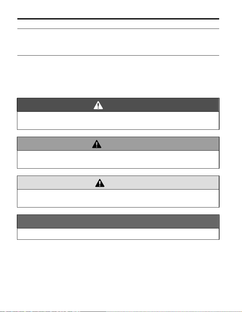
A – Connector (CN5) H – LED (SERVICE)
B – Installation hole I – Service Switch
C–LED (ERR)
D – LED (RUN)
E–LED (TX)
F–LED (RX)<1> M – Terminal block CN1
G – Neuron ID
<1> Refer to Option LED Display on page 12 for details on the LEDs.
<2> The ground wire provided in the option shipping package must be connected during installation .
<1> J – Digital operator connector (CN3)
<1> K – Model number
<1> L – Gr ound terminal and installation hole <2>
Figure 1 LONWORKS Option Components
Underside
10 YASKAWA ELECTRIC TOBP C730600 56A 1000-Series Option SI-W3 Installation Guide
Page 11

4 Option Components
◆ Terminal Block CN1
The communication terminal is a pluggable terminal block that serves as the connection
point of the LONWORKS network communication cable to the option.
Table 2 Terminal Descriptions
Terminal Terminal No. Name Description
1
2
3
1 A Signal Line A
2SLDShield
3 B Signal Line B
◆ Connector CN3 for Digital Operator
DANGER! Electric Shock Hazard. Do not touch drive main terminals and control terminals. Failure to
comply will result in death or serious injury.
Connecting the CN3 and the digital operator (model: JVOP-182) lets the user set the DDC
function parameters.
◆ Service Switch
This is a neuron ID output switch. Pressing this switch outputs the neuron ID to the netwo rk.
■ Initializing Bind Data
Cycling power to the drive while holding down the service switch will clear the bind data,
and reset the configuration properties back to the factory sett ings.
Note: Do not turn off the power to the drive while initializing the bind data. The RUN, RX, TX, and
ERR LEDs are lit (ON) during initialization of the bind data.
YASKAWA ELECTRIC TOBP C730600 56A 1000-Series Option SI-W3 Installation Guide 11
Page 12

4 Option Components
◆ Option LED Display
The option has five LED s .
The operational states of the LEDs are described in Table 3.
Table 3 Option LED States
LED
Name
RUN Green
RX Green
TX Green
ERR Red
SERVICE Green
Display
Color Status
Flashing Network not configured LONWORKS network has not been configured.
OFF
ON/
Flashing
OFF
ON/
Flashing
OFF Not sending data No data is being send
Flashing Comm error CALL or BUSS error has occurred
OFF Normal operation Device is operating normally.
Flashing Network not configured LONWORKS network has not been configured
OFF Normal operation Device is operating normally.
Operating Status Explanation (major faults)
ON Normal operation Device is operating normally.
Power OFF No power is being supplied to the drive.
Hardware fault
Receiving Receiving node data
Node data not yet
received
Sending Sending data
ON Hardware fault
Service switch active Service switch is being held down
ON
Hardware fault
An unrecoverable fault has occurred.
If the unit does not recover after cycling power, then
the option card may need to be replaced.
No input signal
An unrecoverable fault has occurred.
If the unit does not recover after cycling power, then
the option card may need to be replaced.
An unrecoverable fault has occurred.
If the unit does not recover after cycling power, then
the option card may need to be replaced.
Note: The RUN, RX, TX, and ERR LEDs are lit (ON) during initialization of the bind data.
◆ Neuron ID
The neuron ID is written on the side of the service switch. Refer to Figure 1 on page 10 for
details.
The bar code for the neuron ID is included on the device and the packaging.
12 YASKAWA ELECTRIC TOBP C730600 56A 1000-Series Option SI-W3 Installation Guide
Page 13

5 Installation Procedure
DANGER
W ARNING
5 Installation Procedure
◆ Section Safety
Electrical Shock Hazard
Do not connect or disconnect wiring while the power is on.
Failure to comply will result in death or serious injury.
Disconnect all power to the drive and wait at least the amount of time specified on the
drive front cover safety label. After all indicators are off, measure the DC bus voltage to
confirm safe level, and check for unsafe voltages before servicing. The internal capacitor
remains charged after the power supply is turned off.
Electrical Shock Hazard
Do not remove the front covers of the drive while the power is on.
Failure to comply could result in death or serious injury.
The diagrams in this section may include options and drives without covers or safety
shields to show details. Be sure to reinstal l covers or shields before operating any devices.
Use the option according to the instructions described in this manual.
Do not allow unqualified personnel to use equipment.
Failure to comply could result in death or serious injury.
Maintenance, inspection, and replacement of parts must be performed only by authorized
personnel familiar with installation, adjustment, and maintenance of this product.
Do not touch the option card while the power to the drive is on.
Do not touch the drive’s main terminals and control circuit terminals when using the
service switch and digital operator connector on the option unit. Failure to comply could
result in death or serious injury.
YASKAWA ELECTRIC TOBP C730600 56A 1000-Series Option SI-W3 Installation Guide 13
Page 14

5 Installation Procedure
NOTICE
W ARNING
Do not use damaged wires, stress the wiring, or damage the wire insulation.
Failure to comply could result in death or serious injury.
Fire Hazard
Tighten all terminal screws to the specified tightening torque.
Loose electrical connections could result in death or serious injury by fire due to
overheating of electrical connections.
Damage to Equipment
Observe proper electrostatic discharge (ESD) procedures when handling the option,
drive, and circuit boards.
Failure to comply may result in ESD damage to circuitry.
Never shut the power off while the drive is running or outputting voltage.
Failure to comply may cause the application to operate incorrectly or damage the drive.
Do not operate damaged equipment.
Failure to comply may cause further damage to the equipment.
Do not connect or operate any equipment with visible damage or missing parts.
Do not use unshielded cable for control wiring.
Failure to comply may cause electrical interference resulting in poor system performance.
Use shielded twisted-pair wires and ground the shield to the ground terminal of the drive.
Properly connect all pins and connectors.
Failure to comply may prevent proper operation and possibly damage equipment.
Check wiring to ensure that all connections are correct after installing the option
and connecting any other devices.
Failure to comply may result in damage to the option.
14 YASKAWA ELECTRIC TOBP C730600 56A 1000-Series Option SI-W3 Installation Guide
Page 15

5 Installation Procedure
◆ Prior to Installing the Option
Prior to installing the option, wire the drive, make the necessary connections to the drive
terminals, and verify that the drive functions normally. Refer to the Quick Start Guide
packaged with the drive for information on wiring and connecting the drive.
Figure 2 shows an exploded view of the drive with the option and related components for
reference.
Figure 2
N
M
L
K
J
I
H
G
A – Insertion point for CN5 H – Included screws
B – Option card I – Ground wire
C – Front cover J – Option terminal block
D – Digital operator K – Drive grounding terminal (FE)
E – LED label L – Connector CN5-A
F – Terminal cover M – Connector CN5-B
G – Removable tabs for wire routing N – Connector CN5-C
Figure 2 Drive Components with Option
A
B
C
F
D
E
ERR RUN
RX TX
YASKAWA ELECTRIC TOBP C730600 56A 1000-Series Option SI-W3 Installation Guide 15
Page 16

5 Installation Procedure
C
D
F
◆ Installing the Option
Refer to the instructions below to install the option.
1. Shut off power to the drive, wait the appropriate amount of time for voltage to
dissipate, then remove the digital operator (D) and front covers (C, F). Refer to the
Quick Start Guide packaged with the drive for directions on removing the front
covers. Cover removal varies depending on drive size.
DANGER! Electrical Shock Hazard. Disconnect all power to the drive and wait at least the amount of time
specified on the drive front cover safety label. After all indicators are off , measure the DC bus voltage to
confirm safe level, and check for unsafe voltages before servicing to prevent electric shock. The internal
capacitor remains charged even after the power supply is turned off.
NOTICE: Damage to Equipment. Observe proper electrostatic discharge procedures (ESD) when handling
the option, drive, and circuit boards. Failure to comply may result in ESD damage to circuitry.
Figure 3
Figure 3 Remove the Front Covers and Digital Operator
16 YASKAWA ELECTRIC TOBP C730600 56A 1000-Series Option SI-W3 Installation Guide
Page 17
5 Installation Procedure
2. With the front covers and digital operator removed, apply the LED label (E) in the
Figure 4
appropriate position on the drive top front cover (C).
C
ERR RUN
RX TX
E
Figure 4 Apply the LED Label
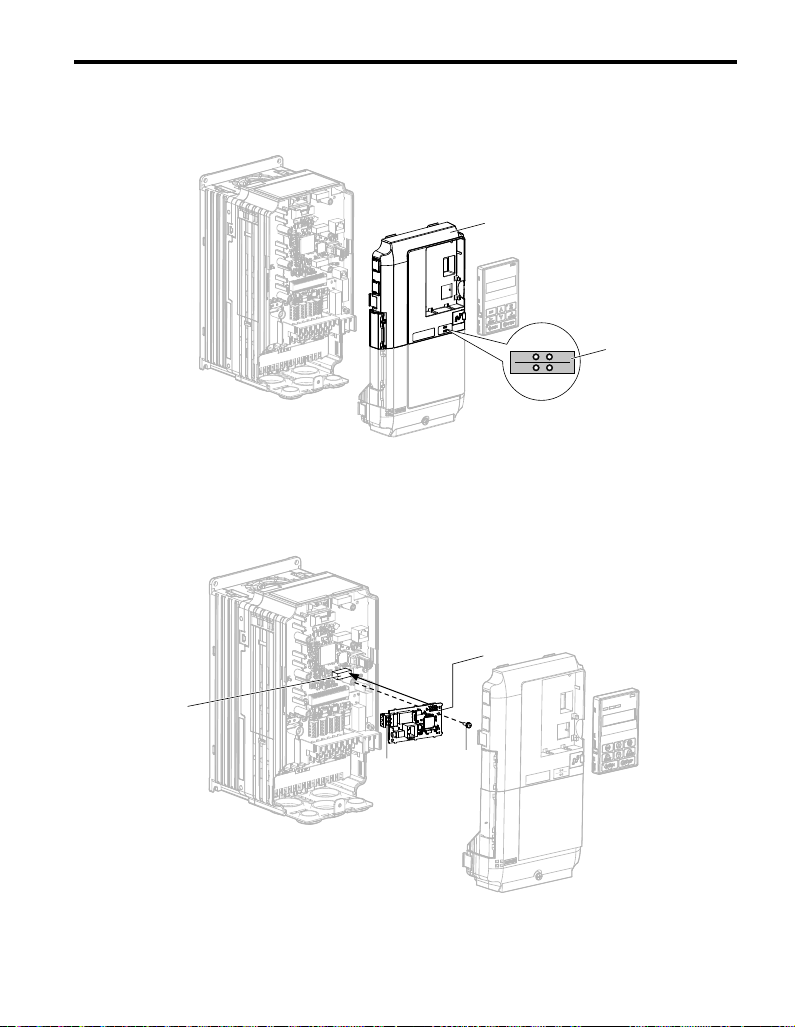
3. Make sure the screws on the left and right sides of the option terminal block (J) are
xm) or 4.4 to 5.43 (inch-lbs), then
B
H
NS MS
Figure 5
tightened with a tightening torque of 0.5 to 0.6 (N
insert the option card (B) into the CN5-A connector (L) located on the drive and
fasten it using one of the included screws (H).
L
J
Figure 5 Insert the Option Card
YASKAWA ELECTRIC TOBP C730600 56A 1000-Series Option SI-W3 Installation Guide 17
Page 18
5 Installation Procedure
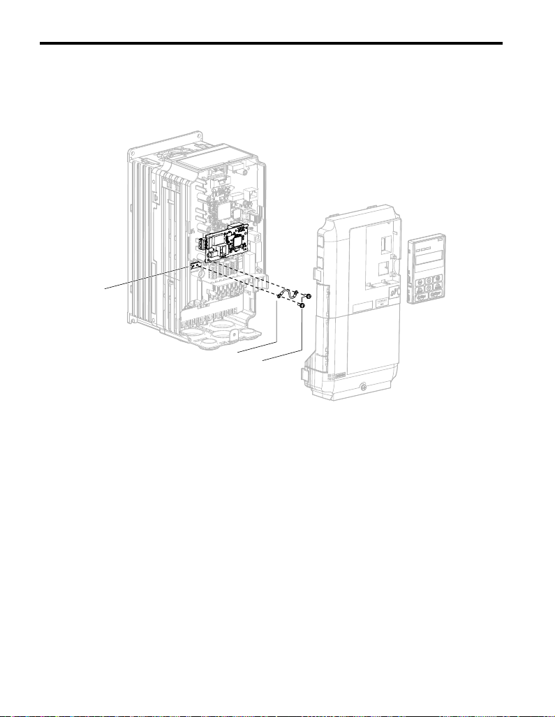
H
I
K
4. Connect the ground wire (I) to the ground terminal (K) using one of the remaining
provided screws (H). Connect the other end of the ground wire (I) to the remaining
ground terminal and installation hole on the option using the last remaining provided
Figure 6
screw (H).
Figure 6 Connect the Ground Wire
Note: There are two screw holes on the drive for use as ground terminals. When connecting more than
two options, two ground wires will need to share the same drive ground terminal.
5. Select the proper type and length of communication cables.
Refer to Wiring Specifications on page 22 for details on selecting cables.
18 YASKAWA ELECTRIC TOBP C730600 56A 1000-Series Option SI-W3 Installation Guide
Page 19

5 Installation Procedure
A SLD B
Preparing wire ends:
Screwdriver blade size
about 5.5 mm (7/32”)
When not using
crimped insulated
sleeves
Pull back the shielding and lightly
twist the end with fingers, keeping
the ends from fraying.
LONWORKS drop line
(do not solder ends)
Blade depth of
0.4 mm or less
Blade width of
2.5 mm or less
Tightening torque:
0.22 to 0.25 N m
or 4.4 to 5.3 in-lbs
Terminal block CN1
Loosen the screws and
insert the wire into the
opening on the terminal block.
6. Prepare and connect the communication cables to the terminal block as shown in
Figure 7 and Figure 8. Take particular precaution to ensure that each wire is
properly connected and wire insulation is not accidentally pinched into electrical
terminals.
WARNING! Fire Hazard. Tighten all terminal screws according to the specified tightening torque. Loose
electrical connections could result in death or serious injury by fire du e to overheating e lectrical connections.
Tightening screws beyond the specified tightening torque may result in erroneo us opera tion, d amage to the
terminal block, or cause a fire.
NOTICE: Heat shrink tubing or electrical tape may be required to ensure that cable shielding does not come
into contact with other wiring. Insufficient insulation may cause a sh ort circuit that can damage the opt ion or
the drive.
Figure 7
Insulation
Shield
Shield
Figure 7 Preparing Ends of Shielded Cable
Note: Separate communication cables from main circuit wiring and other electrical lines.
Figure 8
Shield sheath
(Insulate with electrical tape
or shrink tubing)
YASKAWA ELECTRIC TOBP C730600 56A 1000-Series Option SI-W3 Installation Guide 19
Figure 8 Preparing and Connecting Communication Cable Wiring
Page 20

5 Installation Procedure
<1>
CN5-A
SI-W3
FE
M
U
V
W
R
S
T
A
B
SLD
Drive
Zero phase
reactor
LONWORKS
Network
E
MCCB
Noise filter
Connection Diagram
Figure 9
Figure 9 Option Connection Diagram
<1> Make sure the lead installed to the FE terminal on the option card is connected to the ground terminal on the drive.
20 YASKAWA ELECTRIC TOBP C730600 56A 1000-Series Option SI-W3 Installation Guide
Page 21
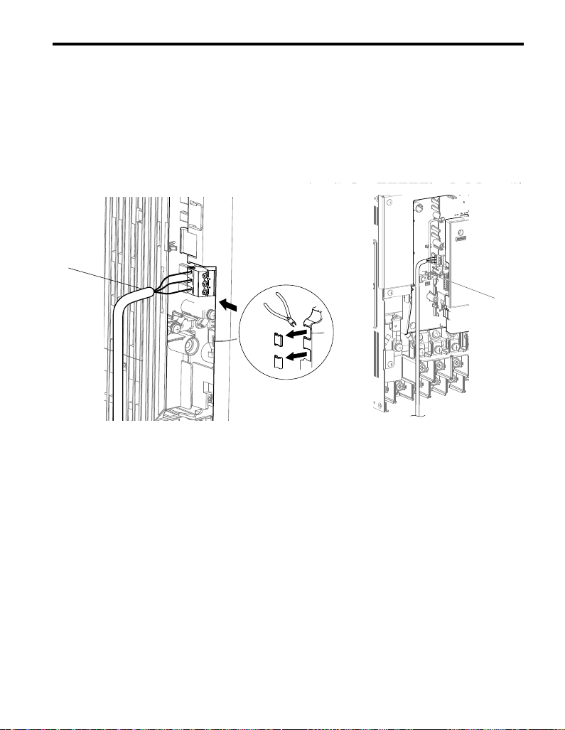
7. Route the option wiring.
B
A
Depending on the drive model, some drives may require routing wire through the
side of the front cover to the outside. In these cases, cut out the perforated openings
in the left side of the drive front cover as shown in Figure 10-A, and leave no sharp
edges to damage wiring.
Route the wiring inside the enclosure as show in Figure 10-B for drives that do not
require routing through the front cover. Refer to the Peripheral Devices & Options
Figure 10
section of the drive Technical Manual for more information.
5 Installation Procedure
A – Route wires through the openings
provided on the left side of the
front cover.
<1> The drive will not meet NEMA Type 1 requirements if wiring is exposed outside the enclosure.
<1>
Figure 10 Wire Routing Examples
B – Use the open space provided
inside the drive to route option
wiring.
YASKAWA ELECTRIC TOBP C730600 56A 1000-Series Option SI-W3 Installation Guide 21
Page 22

5 Installation Procedure
8. After wiring the terminal block, recheck the option wire routing performed in step 7.
9. Replace and secure the front covers of the drive (C, F) and replace the digital
Figure11
operator (D).
C
D
F
Figure 11 Replace the Front Covers and Digital Operator
Note: Take proper precautions when wiring the option so that the front covers will easily fit back onto
the drive. Make sure no cables are pinched between the front covers and the drive when
replacing the covers.
10. Set drive parameters in Table 4 for proper option performance.
◆ Wiring Specifications
Use only the LONWORKS network cables.
Refer to the Echelon web site for more information on network cabling (www.echelon.com).
The performance cannot be guaranteed when using the cables other than LONWORKS
network cables.
Separate the LONWORKS cables from the wiring to the main circuit and other lines.
22 YASKAWA ELECTRIC TOBP C730600 56A 1000-Series Option SI-W3 Installation Guide
Page 23

5 Installation Procedure
◆ Termination
A free topology segment must be terminated. The segment can be terminated anywhere.
Figure 12
Twisted pair terminator
Ra
Ca
100 µF
50 V (min)
Figure 12 RC Network (Ra = 52.3 Ω ±1%, 1/8 W)
Cb
100 µF
50 V (min)
Shielded twisted pair
◆ XIF Files, Resource Files
XIF files and the resource files for this option card are not included. For more information,
either contact Yaskawa's sales department directly or your nearest Yask awa repre se ntative.
YASKAWA ELECTRIC TOBP C730600 56A 1000-Series Option SI-W3 Installation Guide 23
Page 24

6 Related Parameters
6 Related Parameters
The following parameters are used to set up the drive for operation with the option.
Confirm proper setting of the parameters in Table 4 before starting network
communications.
Table 4 Related Parameters
No.
(Addr.
Hex)
b1-01
(180)
b1-02
(181)
F6-01
(3A2)
F6-02
(3A3)
F6-03
(3A4)
F6-06
(3A7)
<2>
F6-07
(3A8)
Name Description Values
Selects the frequency reference input source
Frequency Reference
Selection 1
Run Command
Selection 1
Communications Error
Operation Selection
External Fault from
Comm. Option
Detection Selection
External Fault from
Comm. Option
Operation Selection
Torque Reference/
Torque Limit Selection
from Comm. Option
Multi-Step Speed
Enable/Disable
Selection when
NefRef/ComRef is
Selected
0: Digital Operator - Digital preset speed d1-01 to d1-17
1: Terminals - Analog input terminal A1 or A2
2: MEMOBUS/Modbus communications
3: Option
4: Pulse Input (Terminal RP)
Selects the run command input source
0: Digital Operator - RUN and STOP keys
1: Digital input terminals S
2: MEMOBUS/Modbus communications
3: Option
Determines drive response after a bUS error during
communications with the option
0: Ramp to Stop
1: Coast to Stop
2: Fast-Stop
3: Alarm Only
Sets the condition for external fault detection (EF0)
0: Always detected
1: Detected only during operation
Determines drive response for external fault input (EF0)
detection during LONWORKS communication
0: Ramp to Stop
1: Coast to Stop
2: Fast-Stop
3: Alarm Only
0: Torque reference / torque limit via network
communications are disabled.
1: Torque reference / torque limit via network
communications are enabled.
0: Multi-step speed reference disabled (F7 functionality)
1: Multi-step speed reference allowed (V7 functionality)
<1>
<1>
<3>
Default: 1
Range: 0 to 4
(Set to 3 for
LONWORKS
only)
Default: 1
Range: 0 to 3
(Set to 3 for
LONWORKS
only)
Default: 1
Range: 0 to 3
Default: 0
Range: 0, 1
Default: 1
Range: 0 to 3
Default: 0
Range: 0, 1
Default: 0
Range: 0, 1
24 YASKAWA ELECTRIC TOBP C730600 56A 1000-Series Option SI-W3 Installation Guide
Page 25

6 Related Parameters
No.
(Addr.
Hex)
F6-08
(36A)
<1> Setting F6-01 or F6-03 to 3 will allow the drive to continue to operate after detecting a fault. When allowing the
drive to continue operation after fault detection, be sure to take proper safety measures such as installing an
emergency stop switch.
<2> Enabled in CLV, AOLV/PM, and CLV/PM control modes (A1-02 = 3, 6, or 7). When enabled, d5-01 determines
whether the value is read as the torque limit value (d5-01 = 0) or read as the torque reference value (d5-01 = 1).
This value is read as the torque limit in CLV/PM.
<3> Setting specifies that the torque reference or the torque limit is to be provided with Torque Reference/Torque
Limit Selection from Comm. Option (F6-06 = 1). The motor might not rotate if a torque reference or a torque limit
is not received from the network.
Name Description Values
Reset Communication
Parameters
Determines which F6- and F7- parameters are reset to
default values when initializing the drive using A1-03.
0: Do not reset parameters
1: Reset parameters
Default: 0
Range: 0, 1
YASKAWA ELECTRIC TOBP C730600 56A 1000-Series Option SI-W3 Installation Guide 25
Page 26

7 Network Variables
Drive
nviRequest
nvoStatus
NODE object: 0
Node
Networks Variable
VSD
Networks Variable
VSD object: 6010
Config_Property
nvoDrvSpeed
nvoRunStatus
nvoInvOutFreq
nvoDrvCurrent
nvoInvAlarm
nvoReadParamVal
nvoParamErr
nvoSpdStptFb
nvoSpdCmd
nvoDrvStatus
nvoFltstatus1
nvoFltstatus2
nvoFltstatus3
nvoEmergStatus
nvoDrvVolt
nvoDCBUS
nvoDrvPwr
nvoDrvEnergy
nvoDrvRunHours
nvoInvFault
Logic object:20000
analog object:20001
Select object:20002
Compere object:20003
Stepout object:20004
Dlytimer object:20005
Deviation object:20006
PID object:20007
Constout object:20008
Convtype object:20009
Savedata object:20010
nviDrvSpeedStpt
nviDrvSpeedRef
nviInvSetFreq
nviRunCommand
nviOpCommands
nviDrvSpeedScale
nviEmergOverride
nviDrvEnergyClr
nviFltRstCommand
nviReadParamNum
nviWriteParamNum
nviWriteParamVal
nciMaxSpeed nciRcvHrtBt nciInvSetFreq
nciMinSpeed nciMinOutTm nciDrvSpeedRef
nciSndHrtBt nciLocation nciDrvEngylimit
nciNmlSpeed nciPwupOutTm nciEngyMinDelta
nciNmlFreq nciFreqMinDelta1 nciOpMode
nciRampUpTm nciFreqMinDelta2 nciDrvRunMode
nciRampDownTm nciDrvSpeedScale
7 Network Variables
◆ Drive and Network Variables
Figure 13 outlines the relationship between drive and network variables.
Figure 13
26 YASKAWA ELECTRIC TOBP C730600 56A 1000-Series Option SI-W3 Installation Guide
Figure 13 Drive and Network Variables
Page 27

◆ Node Objects
■ Object Requests
Iput: FSNVT_obj_request nviRequest
Requests the status for each object in a node.
Member Name Description
Object ID number
0 Entire node
1VSD
2 logic [0]
3 logic [1]
4 logic [2]
5 logic [3]
6 logic [4]
7 logic [5]
8 logic [6]
9 logic [7]
10 Analog [0]
object_id
11 Analog [1]
12 Analog [2]
13 Analog [3]
14 Analog [4]
15 Analog [5]
16 Analog [6]
17 Analog [7]
18 Analog [8]
19 Analog [9]
20 Select [0]
21 Select [1]
22 Select [2]
23 Select [3]
7 Network Variables
YASKAWA ELECTRIC TOBP C730600 56A 1000-Series Option SI-W3 Installation Guide 27
Page 28

7 Network Variables
Member Name Description
24 Select [4]
25 Select [5]
26 Select [6]
27 Select [7]
28 Compare [0]
29 Compare [1]
30 Compare [2]
31 Compare [3]
32 Compare [4]
33 Compare [5]
34 Compare [6]
35 Compare [7]
36 Stepout [0]
37 Dlytimer [0]
38 Dlytimer [1]
object_id
39 Deviation [0]
40 Pidmodule [0]
41 Pidmodule [1]
42 Pidmodule [2]
43 Pidmodule [3]
44 Constout [0]
45 Constout [1]
46 Constout [2]
47 Constout [3]
48 Constout [4]
49 Constout [5]
50 Convtype [0]
51 Convtype [1]
52 Convtype [2]
53 Convtype [3]
54 Savedata [0]
55 Savedata [1]
56 Savedata [2]
28 YASKAWA ELECTRIC TOBP C730600 56A 1000-Series Option SI-W3 Installation Guide
Page 29

Member Name Description
object_id
object_request
57 Savedata [3]
Other invalid_id
0 RQ_NORMAL Enables the object.
1 RQ_DISABLED Disable the object
2 RQ_UPDATE_STATUS Not supported. (Normal response)
3 RQ_SELF_TEST Not supported. (Normal response)
4 RQ_UPDATE_ALARM Not supported. (Normal response)
5 RQ_REPORT_MASK
6 RQ_OVERRIDE
7 RQ_ENABLE Enables the object.
8 RQ_RMV_OVERRIDE
9 RQ_CLEAR_STATUS
10 RQ_CLEAR_ALARM
11 RQ_ALARM_NOTIFY_ENABLED
12 RQ_ALARM_NOTIFY_DISABLED
13 RQ_MANUAL_CTRL
14 RQ_REMOTE_CTRL
15 RQ_PROGRAM
0xff RQ_NUL
7 Network Variables
Not supported. (Returns message:
invalid_request.)
Not supported. (Returns message:
invalid_request.)
Not supported. (Returns message:
invalid_request.)
Not supported. (Returns message:
invalid_request.)
Not supported. (Returns message:
invalid_request.)
Not supported. (Returns message:
invalid_request.)
Not supported. (Returns message:
invalid_request.)
Not supported. (Returns message:
invalid_request.)
Not supported. (Returns message:
invalid_request.)
Not supported. (Returns message:
invalid_request.)
Not supported. (Returns message:
invalid_request.)
YASKAWA ELECTRIC TOBP C730600 56A 1000-Series Option SI-W3 Installation Guide 29
Page 30

7 Network Variables
■ Object Status
Output: FSNVT_obj_status nvoStatus
Displays the status of objects in a node.
Member Name Description
object_id Object ID (refer to the object request)
bit 31 invalid_id Turns ON if the object_id specified by nviRequest is invalid.
bit 30 invalid_request Turns ON if the object_request specified by nviRequest is invalid.
bit 29 disabled
bit 28 out_of_limits Not supported. (Always 0.)
bit 27 open_circuit Not supported. (Always 0.)
bit 26 out_of_service Not supported. (Always 0.)
bit 25 mechanical_fault Not supported. (Always 0.)
bit 24 feedback_failure Not supported. (Always 0.)
bit 23 over_range Not supported. (Always 0.)
bit 22 under_range Not supported. (Always 0.)
bit 21 electrical_fault Not supported. (Always 0.)
bit 20 unable_to_measure Not supported. (Always 0.)
bit 19 comm_failure Not supported. (Always 0.)
bit 18 fail_self_test Not supported. (Always 0.)
bit 17 self_test_in_progress Not supported. (Always 0.)
bit 16 locked_out Not supported. (Always 0.)
bit 15 manual_control Not supported. (Always 0.)
bit 14 in_alarm Not supported. (Always 0.)
bit 13 in_override Not supported. (Always 0.)
bit 12 report_mask Not supported. (Always 0.)
bit 11 programming_mode Not supported. (Always 0.)
bit 10 programming_fail Not supported. (Always 0.)
bit 9 alarm_notify_disabled Not supported. (Always 0.)
bit 8 to 0 reserved Always 0.
Indicates whether or not a given object is enabled for operation.
Turns ON when an object is disabled.
30 YASKAWA ELECTRIC TOBP C730600 56A 1000-Series Option SI-W3 Installation Guide
Page 31

◆ VSD Network Variables
■ VSD Network Input Variables
Name Variable Type Description
nviDrvSpeedStpt SNVT_switch Drive Speed Setpoint
nviInvSetFreq SNVT_freq_hz Drive Frequency Reference (Hz)
nviDrvSpeedRef SNVT_lev_percent Drive Speed SetFreq (%)
nviRunCommand SNVT_switch Drive Run Reference
nviOpCommands SNVT_state Drive Operation Commands
nviDrvSpeedScale SNVT_lev_percent Drive Speed Setpoint Scaling
nviEmergOverride SNVT_hvac_emerg Drive Emergency
nviFltRstCommand SNVT_switch Drive Speed Setpoint Scaling
nviDrvEnergyClr SNVT_switch Drive Speed Setpoint Scaling
nviReadParamNum SNVT_count Drive Parameter Read
nviWriteParamNum SNVT_count Drive Parameter Write
nviWriteParamVal SNVT_count_inc Drive Parameter Write Data
■ VSD Network Output Variables
Name Variable Type Description
nvoDrvSpeed SNVT_lev_percent Drive Speed Feedback (%)
nvoRunStatus SNVT_switch Drive Run Status
nvoInvOutFreq SNVT_freq_hz Drive Output Frequency
nvoDrvCurrent SNVT_amp Drive Output Current
nvoDrvVolt SNVT_volt Drive Output Voltage
nvoDCBUS SNVT_volt Drive DC Voltage
nvoDrvPwr SNVT_power_kilo Drive Output Power
nvoDrvEnergy SNVT_elec_kwh_l Cumulative Drive Energy
nvoDrvRunHours SNVT_time_hour Drive Total Running Hours
nvoInvFault SNVT_switch Drive Fault Status
nvoInvAlarm SNVT_switch Drive Alarm Status
nvoReadParamVal SNVT_count_inc Drive Parameter Read Data
nvoParamErr SNVT_count Drive Parameter Error
nvoSpdStptFb SNVT_lev_percent Drive Speed Setpoint Feedback1
nvoSpdCmd SNVT_lev_percent Drive Speed Setpoint Feedback2
nvoDrvStatus SNVT_state Drive Status
nvoFltstatus1 SNVT_state Drive Fault Status1
7 Network Variables
YASKAWA ELECTRIC TOBP C730600 56A 1000-Series Option SI-W3 Installation Guide 31
Page 32

7 Network Variables
Name Variable Type Description
nvoFltstatus2 SNVT_state Drive Fault Status2
nvoFltstatus3 SNVT_state Drive Fault Status3
nvoEmergStatus SNVT_hvac_emerg Drive Emerg Status
32 YASKAWA ELECTRIC TOBP C730600 56A 1000-Series Option SI-W3 Installation Guide
Page 33

8 Drive Configuration Properties
8 Drive Configuration Properties
◆ Drive Related Network Configuration Properties
Table 5 Drive Configuration Properties
Name Variable Type Description
nciMaxSpeed SNVT_lev_percent Maximum Motor Speed
nciMinSpeed SNVT_lev_percent Minimum Motor Speed
nciSndHrtBt SNVT_time_sec Send Heartbeat Time
nciNmlSpeed SNVT_rpm
nciNmlFreq SNVT_freq_hz Nominal Motor Frequency (Motor Rated Frequency)
nciRampUpTm SNVT_time_sec Drive Ramp Up Time (Drive Acceleration Time)
nciRampDownTm SNVT_time_sec
nciRcvHrtBt SNVT_time_sec Receive Heartbeat Time
nciMinOutTm SNVT_time_sec Minimum Send Time
nciLocation SNVT_str_asc Location Label
nciPwupOutTm SNVT_time_sec P ower delay Timer
nciFreqMinDelta1 SNVT_lev_percent
nciFreqMinDelta2 SNVT_ freq_hz
nciDrvSpeedScale SNVT_lev_percent nviDrvSpeedScale Default
nciInvSetFreq SNVT_ freq_hz nviInvSetFreq Default
nciDrvSpeedRef SNVT_lev_percent nviDrvSpeedRef Default
nciDrvEngylimit SNVT_elec_kwh_l
nciEngyMinDelta SNVT_elec_kwh_l
nciOpMode SNVT_count Reference Selection Mode
nciDrvRunMode SNVT_switch Run Command Status Mode
Nominal Motor Speed in RPM
(Motor Rated Rotation Frequency)
Minimum Ramp Down Time
(Minimum Deceleration Time)
Output Frequency Monitor Minimum Change Range
Setting 1 (nciFreqMinDelta1)
Output Frequency Monitor Minimum Change Range
Setting 2 (nciFreqMinDelta2)
Cumulative Power Monitor Upper Limit:
nciDrvEngylimit
Cumulative Power Monitor Minimum Change Range
Setting
YASKAWA ELECTRIC TOBP C730600 56A 1000-Series Option SI-W3 Installation Guide 33
Page 34

9 Troubleshooting
9 Troubleshooting
◆ Drive-Side Error Codes
Table 6 lists the various option-related fault codes. Refer to the drive Technical Manual for
further information about fault codes.
■ Faults
Both bUS (Option Communication Error) and EF0 (External Fault Input from the option)
can appear as either an alarm or as a fault. When a fault occurs, the digital operator ALM
LED remains lit. When an alarm occurs, the digital operator ALM LED flashes.
Check the following items first when an error code occurs on the drive:
• Communication cable connections
• Make sure the option is properly installed to the drive
• Did a momentary power loss interrupt communications?
Table 6 Fault Displays, Causes, and Possible Solutions
Digital Operator Display Fault Name
Option Communication Error
bUS
Cause Possible Solution
Network has stopped communicating
Communication cable is not connected
properly
A data error occurred due to noise
Option is damaged
Connection timeout
The connection was lost after establishing initial communication.
Only detected when the run command frequency reference is assigned to
the option
(bl-01 = 3 or bl-02 = 3).
Check for faulty wiring.
Correct any wiring problems.
• Counteract noise in the control circuit wiring, main circuit lines, and
ground wiring.
• If a magnetic contactor is the noise source, install a surge absorber to the
contactor coil.
• Use only the LONWORKS network cables.
Ground the shield on the controller side and on the option side.
If there are no wiring problems and the fault continues to occur, replace
the option.
The option Receive Heart Beat timer timed out.
Make sure that Receive Heart Beat time is set properly.
Check the option connection and communication signal.
34 YASKAWA ELECTRIC TOBP C730600 56A 1000-Series Option SI-W3 Installation Guide
Page 35

9 Troubleshooting
Digital Operator Display Fault Name
EF0
Cause Possible Solution
An external fault is being sent from the
network
Problem with the network program
Digital Operator Display Fault Name
oFA00
Cause Possible Solution
Non-compatible option connected to
drive port CN5-A
Digital Operator Display Fault Name
oFA01
Cause Possible Solution
Problem with the connector between the
drive and option
Digital Operator Display Fault Name
to
oFA30 to oFA43
Cause Possible Solution
Option hardware fault Replace the option. Contact Yaskawa for assistance.
Digital Operator Display Fault Name
oFb00
Cause Possible Solution
Non-compatible option connected to
drive port CN5-B
External Fault Input from the option
The alarm function for an external device has been triggered.
• Remove the cause of the external fault
• Reset the external fault input from the network
Check the program used by the network and make the appropriate
corrections.
Non-Compatible Option connected to drive port CN5-A
Option is not properly connected.
Use only compatible options. Connect the SI-W3 to CN5-A. For other
option connections refer to the Installation Manual for those options.
Option Fault (CN5-A)
Option is not properly connected.
Turn the power off and check the connectors between the drive and option.
Option Fault (CN5-A)
Communication ID error.
Non-Compatible Option connected to drive port CN5-B
Non-compatible option is connected.
Use only compatible options. Connect the SI-W3 to CN5-A. For other
option connections refer to the Installation Manual for those options.
YASKAWA ELECTRIC TOBP C730600 56A 1000-Series Option SI-W3 Installation Guide 35
Page 36

9 Troubleshooting
Digital Operator Display Fault Name
oFb02
Cause Possible Solution
Options AI-A3 or D1-A3 connected to
the CN5-B port while an option was
connected to CN5-A
Digital Operator Display Fault Name
oFc00
Cause Possible Solution
Non-compatible option connected to
port CN5-C
Digital Operator Display Fault Name
oFc02
Cause Possible Solution
Options AI-A3 or D1-A3 connected to
the CN5-C port while an option was
connected to CN5-A
■ Minor Faults and Alarms
Digital Operator Display Minor Fault Name
CALL
Cause Possible Solution
Communication wiring or terminal
resistor connection is faulty. There is a
short circuit, or an option component is
not connected properly
Network programming error
Damaged communication circuitry
Option Fault (CN5-B)
Two of the same option are connected simultaneously.
Only one of these options, AI-A3, DI-A3 or SI- option can be
connected to the drive at the same time. The SI-W3 must be connected to
CN5-A.
Non-Compatible Option connected to drive port CN5-C
Non-compatible option is connected.
Use only compatible options. Connect the SI-W3 to CN5-A. For other
option connections refer to the Installation Manual for those options.
Option Fault (CN5-C)
Two of the same options are connected simultaneously.
Only one of these options, AI-A3, DI-A3 or SI- option can be
connected to the drive at the same time. The SI-W3 must be connected to
CN5-A.
Serial Communication Transmission Error
Communication has not yet been established.
Check for wiring errors and correct the wiring.
Remove any ground shorts and reconnect loose wires.
Check communications at start-up and correct
programming errors.
Cycle power to the drive and replace the drive if the fault
continues to occur.
Minor Fault
(H2- = 10)
Yes
36 YASKAWA ELECTRIC TOBP C730600 56A 1000-Series Option SI-W3 Installation Guide
Page 37

10 Specifications
10 Specifications
Table 7 Option Specifications
Items Specifications
Model SI-W3
Note Type Host Application Node
Communication Speed 78 kbps
Communication IC Neuron chip FT3120
Communication Driver FT-X1 (free topology)
Protocol LonTalk protocol node
Network Variables
Network Variable Alias Maximum: 50
Maximum Number of
Connections
Total Wiring Length Max 500 m
Ambient Temperature -10°C to +50°C (14°F to 122°F)
Humidity 95% RH or lower with no condensation
Storage Temperature -20°C to +60°C (-4°F to 140°F) allowed for short-term transport of the product
Area of Use Indoor (free of corrosive gas, airborne particles, etc.)
Altitude 1000 m (3280 ft.) or lower
Total: 236
Standard Network Variable Types (SNVT): Variable Speed Motor Drive function profile
Ver1.1
64 (in one segment)
YASKAWA ELECTRIC TOBP C730600 56A 1000-Series Option SI-W3 Installation Guide 37
Page 38

10 Specifications
QSG_only
◆ Revision History
Revision dates and manual numbers appear on the bottom of the back cover.
MANUAL NO.ޓTOBP C730600 56A
Published in Japan November 2011 11-11
Date of original publication
Date of publication
Date of
Publication
November 2011 −−First edition
Revision
Number
Section Revised Content
38 YASKAWA ELECTRIC TOBP C730600 56A 1000-Series Option SI-W3 Installation Guide
Page 39

This Page Intentionally Blank
Page 40

YASKAWA AC Drive 1000-Series Option
LONWORKS
Installation Manual
DRIVE CENTER (INVERTER PLANT)
2-13-1, Nishimiyaichi, Yukuhashi, Fukuoka, 824-8511, Japan
Phone: 81-930-25-3844 Fax: 81-930-25-4369
http://www.yaskawa.co.jp
YASKAWA ELECTRIC CORPORATION
New Pier Takeshiba South Tower, 1-16-1, Kaigan, Minatoku, Tokyo, 105-6891, Japan
Phone: 81-3-5402-4502 Fax: 81-3-5402-4580
http://www.yaskawa.co.jp
YASKAWA AMERICA, INC.
2121 Norman Drive South, Waukegan, IL 60085, U.S.A.
Phone: (800) YASKAWA (927-5292) or 1-847-887-7000 Fax: 1-847-887-7310
http://www.yaskawa.com
YASKAWA ELÉTRICO DO BRASIL LTDA.
Avenda Fagundes Filho, 620 Bairro Saude, São Paulo, SP04304-000, Brasil
Phone: 55-11-3585-1100
http://www.yaskawa.com.br
YASKAWA EUROPE GmbH
Hauptstrasse 185, 65760 Eschborn, Germany
Phone: 49-6196-569-300 Fax: 49-6196-569-398
http://www.yaskawa.eu.com
YASKAWA ELECTRIC UK LTD.
1 Hunt Hill Orchardton Woods, Cumbernauld, G68 9LF, United Kingdom
Phone: 44-1236-735000
http://www.yaskawa.co.uk
YASKAWA ELECTRIC KOREA CORPORATION
7F, Doore Bldg. 24, Yeoido-dong, Yeoungdungpo-gu, Seoul, 150-877, Korea
Phone: 82-2-784-7844
http://www.yaskawa.co.kr
YASKAWA ELECTRIC (SINGAPORE) PTE. LTD.
151 Lorong Chuan, #04-01, New Tech Park, 556741, Singapore
Phone: 65-6282-3003
http://www.yaskawa.com.sg
YASKAWA ELECTRIC (SHANGHAI) CO., LTD.
No. 18 Xizang Zhong Road, 17F, Harbour Ring Plaza, Shanghai, 200001, China
Phone: 86-21-5385-2200
http://www.yaskawa.com.cn
YASKAWA ELECTRIC (SHANGHAI) CO., LTD. BEIJING OFFICE
Room 1011, Tower W3 Oriental Plaza, No. 1 East Chang An Ave.,
Dong Cheng District, Beijing, 100738, China
Phone: 86-10-8518-4086
YASKAWA ELECTRIC TAIWAN CORPORATION
9F, 16, Nanking E. Rd., Sec. 3, Taipei, 104, Taiwan
Phone: 886-2-2502-5003
Fax: 55-11-5581-8795
Fax: 44-1236-458182
Fax: 82-2-784-8495
Fax: 65-6289-3003
Fax: 86-21-5385-3299
Fax: 86-10-8518-4082
Fax: 886-2-2505-1280
YASKAWA ELECTRIC CORPORATION
In the event that the end user of this product is to be the military and said product is to be employed in any weapons systems or the manufacture
thereof, the export will fall under the relevant regulations as stipulated in the Foreign Exchange and Foreign Trade Regulations. Therefore, be sure
to follow all procedures and submit all relevant documentation according to any and all rules, regulations and laws that may apply.
Specifications are subject to change without notice for ongoing product modifications and improvements.
© 2011 YASKAWA ELECTRIC CORPORATION. All rights reserved.
MANUAL NO. TOBP C730600 56A
Published in Japan November 2011 11-11
10-10-6
Page 41

This Page Intentionally Blank
Page 42

Copyright © 2011 株式会社 安川電機
本書の内容の一部または全部を,当社の文書による許可なしに,転載または複製するこ
とは,固くお断り致します。
2 ㈱安川電機 TOBP C730600 56A 1000 シリーズオプション SI-W3 取扱説明書
Page 43

目次
1 ご使用になる前に . . . . . . . . . . . . . . . . . . . . . . . . . . . . . . . . . .4
2 製品の概要 . . . . . . . . . . . . . . . . . . . . . . . . . . . . . . . . . . . . . . . .8
3 製品が届いたら . . . . . . . . . . . . . . . . . . . . . . . . . . . . . . . . . . . .9
4 各部の名称 . . . . . . . . . . . . . . . . . . . . . . . . . . . . . . . . . . . . . . .10
5 取付けと配線 . . . . . . . . . . . . . . . . . . . . . . . . . . . . . . . . . . . . .13
6 関連するパラメータ. . . . . . . . . . . . . . . . . . . . . . . . . . . . . . . .24
7 ネットワーク変数 . . . . . . . . . . . . . . . . . . . . . . . . . . . . . . . . .26
8 ドライブコンフィグレーションプロパティ. . . . . . . . . . . . . . 32
9 異常診断とその対策. . . . . . . . . . . . . . . . . . . . . . . . . . . . . . . .33
10 仕様と保証について. . . . . . . . . . . . . . . . . . . . . . . . . . . . . . .36
㈱安川電機 TOBP C730600 56A 1000 シリーズオプション SI-W3 取扱説明書 3
Page 44

1 ご使用になる前に
1 ご使用になる前に
◆ 取扱説明書について
本オプションカードに関連する取扱説明書には以下のものがあります。目的に応じてご
利用ください。
オプションカード
安川インバータ
1000 シリーズ オプション
LONWORKS 通信
取扱説明書
資料番号:TOBP C730600 56
(本書)
安川インバータ
1000 シリーズ オプション
LONWORKS 通信
テクニカルマニュアル
資料番号:SIJP C730600 56
インバータ本体
安川インバータ 1000 シリーズ
クイックスタートガイド
安川インバータ 1000 シリーズ
テクニカルマニュアル
最初にお読みください。
本製品をお使いいただくうえで基本とな
る,配線,設定,機能,異常診断について
説明しています。ご購入時,オプション
カードに同梱されています。
本製品についてさらに詳しい使い方が知り
たいときにお読みください。取扱説明書に
は記載されていない詳細な内容を確認でき
ます。製品には同梱されておりませんの
で,当社の製品・技術情報サイト
(http://www.e-mechatronics.com/) からご覧
ください。
本オプションカードを取付けるインバータ
の取扱説明書を参照してください。
本オプションカードをお使いいただくうえ
で基本となる,据え付け,配線,操作手
順,機能,異常診断,保守点検を詳細に説
明しています。
パラメータの基本設定や,調整方法につい
ても説明しています。
クイックスタートガイドは,インバータに
同梱されています。テクニカルマニュアル
は,インバータには同梱されておりません
ので,当社の製品・技術情報サイト
(http://www.e-mechatronics.com/) からご覧
ください。
◆ 本書中の用語・略称について
(注) 守っていただきたい重要な事柄です。また,インバータのアラーム表示が発生するな
ど,装置の損傷には至らないレベルの軽度の注意事項や,補足事項を示します。
オプションカード 安川インバータ 1000 シリーズオプション LONWORKS 通信
◆ 登録商標について
•LONWORKS及び LonTalk は米国 Echelon 社の登録商標です。
• その他,本文中に記載してある会社名,製品名は,各社の商標または登録商標です。
4 ㈱安川電機 TOBP C730600 56A 1000 シリーズオプション SI-W3 取扱説明書
Page 45

1 ご使用になる前に
危険
警告
注意
重要
◆ 安全に関するシンボルマーク
オプションカードの配線・設定,操作をする前に,本取扱説明書をよくお読みくださ
い。オプションカードは,本取扱説明書の記載内容と現地の規格に従って設置してくだ
さい。
以下のシンボルマークは,本取扱説明書内での安全に関する重要な記載を示すために使
用されます。これらの注意事項をお守りいただけない場合は,死亡または重傷につなが
る可能性や,本製品や関連機器及びシステムの破損につながるおそれがあります。
取扱いを誤った場合に,死亡または重傷につながる危険が生じる可能性があり,その危険
の切迫度が高いことが想定されます。
取扱いを誤った場合に,死亡または重傷につながる危険が生じる可能性があります。
取扱いを誤った場合に,軽傷を受ける危険が生じる可能性があります。
取扱いを誤った場合に,物的損害が発生するおそれがあります。
㈱安川電機 TOBP C730600 56A 1000シリーズオプション SI-W3 取扱説明書 5
Page 46

1 ご使用になる前に
危険
■ 安全上のご注意
一般注意事項
• 取扱説明書に掲載している図解は,細部を説明するために,カバーまたは安全のための
遮へい物を取り外した状態で描かれている場合があります。この製品を運転するとき
は,必ず規定どおりのカバーや遮へい物を元通りに戻し,取扱説明書に従って運転して
ください。
• 取扱説明書に掲載している図は,代表事例であり,お届けした製品と異なる場合があり
ます。
• 取扱説明書は,製品の改良や仕様変更,及び取扱説明書自身の使いやすさの向上のため
に適宜変更することがあります。
• 取扱説明書を注文される場合は,当社代理店または取扱説明書の裏表紙に記載している
最寄りの当社営業所に,表紙の資料番号を連絡してください。
本取扱説明書に記載された,安全にかかわるすべての情報にご留
意ください。
警告事項をお守りいただけない場合は,死亡または重傷につながるおそれもありますの
で,ご留意ください。
貴社または貴社の顧客において,本取扱説明書の記載内容を守らないことにより生じた,
傷害や機器の破損に対して,当社はいっさいの責任を負いかねます。
6 ㈱安川電機 TOBP C730600 56A 1000 シリーズオプション SI-W3 取扱説明書
Page 47

1 ご使用になる前に
重要
インバータやオプションカードの内部の回路を変更しないでくだ
さい。
インバータ,またはオプションカードが破損するおそれがあります。貴社及び貴社顧客に
おいて製品の改造がなされた場合は当社の保証外とさせていただきます。
輸送・設置時の木質梱包財(木枠,合板,パレットなど含む)の
消毒・除虫処理についてのご注意
梱包用木質材料の消毒・除虫が必要な場合は,必ずくん蒸以外の方法を採用してくださ
い。
例:熱処理(材心温度 56°C 以上で 30 分間以上)
くん蒸処理をした木質材料にて電気製品(単体あるいは機械などに搭載したもの)を梱包
した場合,そこから発生するガスや蒸気により電子部品が致命的なダメージを受けること
があります。特にハロゲン系消毒剤(フッ素・塩素・臭素・ヨウ素など)はコンデンサ内
部の腐食の原因となります。
また,梱包後に全体を処理する方法ではなく,梱包前の材料の段階で処理してください。
㈱安川電機 TOBP C730600 56A 1000シリーズオプション SI-W3 取扱説明書 7
Page 48

2 製品の概要
2 製品の概要
◆ 本製品について
LONWORKS 通信オプションカード(形式:SI-W3)は,LonTalk に準拠しています。
インバータを LONWORKS ネットワークに接続し,LonTalk プロトコルを用いて,
データ通信を行うためのインタフェースです。
インバータにオプションカードを装着すると,LonTalk プロトコルに準拠したデバイス
から以下の操作ができます。
• インバータの運転/停止
• インバータの運転状況のモニタ
• インバータのパラメータの設定変更/参照
◆ 対応するインバータ
本オプションカードは,以下のインバータに対応しています。
表 1 対応するインバータ
インバータ
A1000
<1> インバータのネームプレートにある PRG 欄に表示されています。
ソフトウェアバージョン <1>
1017 以降
8 ㈱安川電機 TOBP C730600 56A 1000 シリーズオプション SI-W3 取扱説明書
Page 49

3 製品が届いたら
取扱説明書
3 製品が届いたら
製品がお手元に届きましたら,以下の項目を確認してください。
• オプションカードに傷や汚れが付いていないか,外観を点検してください。
製品搬送時の損傷は当社の保証範囲外とさせていただきます。製品に損傷があった
場合は,直ちに運送業者にご連絡ください。
• ご注文どおりの製品かどうか,基板に印刷している形式「SI-W3」を確認してくださ
い。印刷場所については図 1 を参照してください。
• 製品に不具合がありましたら,直ちにご購入いただいた代理店または当社の営業所
へご連絡ください。
◆ 梱包内容の確認
表 2 梱包内容
梱
包
品
数
量
オプションカード
1131 11
リード線
(接地用)
ねじ (M3) LED ラベル バーコードラベル 取扱説明書
*123456789ABC*
ERR RUN
RX TX
*123456789ABC*
*123456789ABC*
◆ 必要な工具
オプションカードをインバータに取付けるときには,以下の工具 が必要です。
• ドライバ ⊕ (M3)
• ドライバ (M2,先端部厚さ:0.4 mm,先端幅:2.5 mm)
(注) 通信ケーブル側のコネクタをお客様が作成される場合,別途工具が必要になります。
㈱安川電機 TOBP C730600 56A 1000シリーズオプション SI-W3 取扱説明書 9
Page 50

4 各部の名称
D
B
C
A
E
F
L K J I H G
M
裏面
4 各部の名称
◆ オプションカード
ê}1
A–インバータ接続用コネクタ (CN5)
B–取付穴 I–サービススイッチ
C – LED (ERR)
D – LED (RUN)
E– LED (TX)
F– LED (RX) <1>
G– ニューロン ID 表示
<1> LED の表示内容については,「LED 表示」(12 ページ)を参照してください。
<2> オプションカード取付時に,必ず同梱のリード線(接地用)を接続してください。
10 ㈱安川電機 TOBP C730600 56A 1000 シリーズオプション SI-W3 取扱説明書
<1>
<1>
<1>
図 1 オプションカード
H – LED (SERVICE)
J–オペレータ接続用コネクタ (CN3)
K–基板形式
L–接地端子(取付穴)<2>
M–端子台 CN1
Page 51

4 各部の名称
1
2
3
◆ 端子台 CN1
端子台 CN1 を使用して,オプションカードを LONWORKS ネットワークに接続しま
す。端子台は,基板から取り外すことができます。
表 3 端子台の詳細
図 端子番号 名称 詳細
1A
シグナルライン
2SLD
3B
通信シールド
シグナルライン
◆ オペレータ接続用コネクタ CN3
危険 ! インバータの主回路端子,制御回路端子に触れないでください。取扱いを誤った場合は,感電のお
それがあります。
オペレータ接続用コネクタ (CN3) にディジタルオペレータ(形式:JVOP-182)を接続
して,DDC ファンクションパラメータを設定することができます。
◆ サービススイッチ
ニューロン ID 出力スイッチです。サービススイッチを押すとニューロン ID がネット
ワークへ出力されます。
■ バインド情報の初期化
サービススイッチを押しながら,インバータの電源を投入するとバインド情報がクリア
され,コンフィグプロパティの設定が出荷時設定になります。
(注) バインド情報初期化中はインバータの電源を遮断しないでください。バインド情報の
初期化中は RUN,RX,TX,ERR の LED が点灯します。
㈱安川電機 TOBP C730600 56A 1000シリーズオプション SI-W3 取扱説明書 11
Page 52

4 各部の名称
◆ LED 表示
オプションカードには 5 種類の LED があります。
表 4 の動作状態で LED が点灯/点滅します。
表 4 LED 表示
LED の名称
RUN
RX
TX
ERR
SERVICE
(注) バインド情報の初期化中は RUN,RX,TX,ERR の LEDが点灯します。
表示
色 状態
点灯 正常 正常に動作している。
点滅
緑
消灯
点灯/点滅 受信中 自局宛データ受信中
緑
緑
赤
緑
消灯
点灯/点滅 送信中 データ送信中
消灯 送信なし データ送信していない。
点灯
点滅 通信異常
消灯 正常 正常に動作している。
点灯
点滅
消灯 正常 正常に動作している。
動作状態 詳細(主な異常)
ネットワーク
未構成状態
電源 OFF
ハードウェア
異常
自局宛データ
受信なし
ハードウェア
異常
サービスス
イッチ押下時
ハードウェア
異常
ネットワーク
未構成状態
LONWORKS ネットワークに構成されていない。
電源が供給されていない。
回復不可能な異常が発生している。
電源遮断し再投入しても回復しない場合,オプ
ションカードの交換が必要となる場合がありま
す。
受信信号なし
回復不可能な異常が発生している。
電源遮断し再投入しても回復しない場合,オプ
ションカードの交換が必要となる場合がありま
す。
CALL 発生中,BUS 発生中
サービススイッチが押されている。
回復不可能な異常が発生している。
電源を再投入しても回復しない場合,オプショ
ンカードの交換が必要となる場合があります。
LONWORKS ネットワークに構成されていない。
◆ ニューロン ID
ニューロン ID は,サービススイッチの側に記載されています。詳細は,図 1 を参照し
てください。
ニューロン ID のバーコードラベルが製品と同梱されています。
12 ㈱安川電機 TOBP C730600 56A 1000 シリーズオプション SI-W3 取扱説明書
Page 53

5 取付けと配線
危険
警告
5 取付けと配線
◆ 安全上のご注意
感電防止のために
オプションカードを接続するときは,事前にインバータの電源をお切りください。
取扱いを誤った場合は,感電のおそれがあります。
インバータに記載された時間内はフロントカバー,ターミナルカバーを取り外さないでく
ださい。作業前にすべての表示灯が消灯し,主回路直流電圧が安全なレベルになったこと
を確認してください。電源を切っても,インバータの内部コンデンサに電圧が残存してい
ます。
感電防止のために
インバータのフロントカバーを外したまま,運転しないでください。
取扱いを誤った場合は,感電のおそれがあります。
本取扱説明書に掲載している図解は,細部を説明するために,カバーまたは安全のための
遮へい物を取り外した状態で描かれている場合があります。この製品を運転するときは,
必ず規定どおりのカバーや遮へい物を元通りに戻し,取扱説明書に従って運転してくださ
い。
電気工事の専門家以外は,保守・点検・部品交換をしないでください。
感電のおそれがあります。
配線・設定,操作は,オプションカードの設置,調整,修理に詳しい人が行ってくださ
い。
インバータの通電中は,オプションカードに触れないでください。
オプションカードのサービススイッチ,オペレータポートを使用する際は,インバータ主
回路端子,制御回路端子に触れないでください。
取扱いを誤った場合は,感電のおそれがあります。
ケーブルは傷つけたり,無理なストレスをかけたり,重たいものを載せたり,挟み込んだ
りしないでください。
感電のおそれがあります。
火災防止のために
端子ねじは指定された締め付けトルクで締め付けてください。
主回路電線の配線接続部に緩みがあると,電線接続部のオーバーヒートにより火災のおそ
れがあります。
㈱安川電機 TOBP C730600 56A 1000シリーズオプション SI-W3 取扱説明書 13
Page 54

5 取付けと配線
重要
機器破損防止のために
オプションカードを扱うときは,静電気 (ESD) 対策の決められた手順に従ってください。
取扱いを誤ると,静電気によって,基板上の回路が破損するおそれがあります。
インバータの電圧出力中は,電源を外さないでください。
取扱いを誤ると,インバータが破損するおそれがあります。
破損した機器を運転しないでください。
さらに機器の破損が進行するおそれがあります。
明らかな破損や紛失した部品がある機器を接続したり,操作しないでください。
端子ねじは指定された締め付けトルクで締め付けてください。
端子台が破損するおそれがあります。
配線時には,指定品でないケーブルを使用しないでください。
動作不良の原因となります。
当社の推奨するケーブルを使用してください。
コネクタはしっかりと挿入してください。
機器の誤動作・破損の原因となります。
インバータとその他の機器の配線が完了したら,すべての配線が正しいかどうか確認して
ください。
配線を誤ると,オプションカードが破損するおそれがあります。
14 ㈱安川電機 TOBP C730600 56A 1000 シリーズオプション SI-W3 取扱説明書
Page 55

5 取付けと配線
ERR RUN
RX TX
F
H
K
L
M
N
I
B
C
D
E
A
G
J
◆ 取付けの前に
オプションカードを取付ける前に,必ずインバータの端子台の配線を行ってください。
オプションカード接続前にインバータが正常に動作するか確認してください。インバー
タの接続・配線に際しては,インバータの取扱説明書を参照してください。
インバータと各部品の展開図を図 2 に示します。
ê}2
A–接続コネクタ (CN5) を差し込む。 H–ねじ
B–オプションカード I–リード線
C–フロントカバー J–端子台
D–オペレータ K–インバータ側接地端子 (FE)
E–LEDラベル L–接続コネクタ CN5-A
F–ターミナルカバー M–接続コネクタ CN5-B
G–ケーブル配線スペースカバー
(切り取り可能)
図 2 各部の名称
N–接続コネクタ CN5-C
㈱安川電機 TOBP C730600 56A 1000シリーズオプション SI-W3 取扱説明書 15
Page 56

5 取付けと配線
C
D
F
◆ オプションカードの取付け
以下の手順に従ってオプションカードを取付けてください。
1. インバータの主回路電源を遮断後, インバータに記載された時間以上待ってからオ
ペレータ (D),フロントカバー (C),ターミナルカバー (F) を取り外します。フロ
ントカバー,ターミナルカバー,オペレータの取り外し・取付けについては,オ
プションカードを取付けるインバータの取扱説明書を参照してください。
危険 ! 感電防止のために。インバータに記載された時間内はフロントカバー,ターミナルカバーを取り外
さないでください。作業前にすべての表示灯が消灯し,主回路直流電圧が安全なレベルになったこ
とを確認してください。電源を切っても,インバータの内部コンデンサに電圧が残存しています。
重要:機器破損防止のために。オプションカードを扱うときは,静電気 (ESD) 対策の決められた手順に
従ってください。取扱いを誤ると,静電気によって,基板上の回路が破損するおそれがあります。
ê}3
図 3 オペレータ,フロントカバー,ターミナルカバーの取り外し
16 ㈱安川電機 TOBP C730600 56A 1000 シリーズオプション SI-W3 取扱説明書
Page 57

5 取付けと配線
2. フロントカバー (C) とオペレータを取り外した状態で,LED ラベル (E) をフロント
ê}4
カバー下部の図に示す位置に貼り付けてください。
C
ERR RUN
RX TX
E
図 4 LED ラベルの貼り付け
3. オプションカード (B) をインバータの CN5-Aコネクタ (L) に接続し,同梱のねじ (H)
ê}5
で固定してください。
L
B
H
図 5 オプションカードの取付け
NS MS
㈱安川電機 TOBP C730600 56A 1000シリーズオプション SI-W3 取扱説明書 17
Page 58

5 取付けと配線
H
I
K
4. リード線 (I) を同梱のねじ (H) でオプションカードの接地端子(取付穴)に接続し,
ê}6
もう一方をインバータの接地端子 (K) に接続してください。
図 6 リード線の接続
(注) インバータ側の接地端子には 2 つしかねじ穴がありません。オプションカードを 3 枚
取付ける場合は,リード線の端子を重ねて接続してください。
5. LONWORKS 通信専用ケーブルを選定します。ケーブル長の詳細については,「通
信ケーブルの仕様」(22 ページ)を参照してください。
18 ㈱安川電機 TOBP C730600 56A 1000 シリーズオプション SI-W3 取扱説明書
Page 59

5 取付けと配線
6. 図 7のとおりに LONWORKS 専用ケーブルを末端処理し,図 8 のとおりにオプショ
ンカードにケーブルを接続します。端子台 CN1 を基板に接続するときは,端子台
CN1 が確実に固定されたことを確認してください。
また,すべてのケーブルが確実に固定され,ケーブルの被覆が端子台の挿入部に
噛み込んでいないことを確認してください。はみ出している心線はすべて切断し
てください。
警告 ! 端子ねじは指定された締め付けトルクで締め付けてください。配線接続部に緩みがあると,電線接
続部のオーバヒートにより火災のおそれがあります。また,指定した以上の締め付けトルクでの締
め付けは,機器の誤作動 • 破損,または火災の原因になります。
重要:シールド線は他の信号線や機器に接触しないように,熱収縮チューブやテープなどで絶縁してくだ
さい。 絶縁を怠ると,回路の短絡によりオプションカードまたはインバータの破損の原因になりま
す。
ê}7
外被
シールド外覆
ê}8
ケーブルの先端処理 ドライバの大きさ
ケーブルの被覆をむいたら心線がば
らばらにならないよう,指で軽く心
線をより直してください。
約5.5 mm
棒端子を
(
使用しないとき
熱収縮チューブやテープなどで
絶縁してください。
図 7 シールド線の端末処理
(
ねじを緩めて,挿入部が開口
したらケーブルを挿入してく
ださい。
LONWORKS 通信ケーブル
(ハンダ処理をしないこと)
シールド外覆
先端部厚さ
0.4 mm以下
2.5 mm以下
(締め付けトルク:
ޓ0.22〜0.25 ( N m))
ASLDB
端子台CN1
図 8 通信ケーブルの配線
㈱安川電機 TOBP C730600 56A 1000シリーズオプション SI-W3 取扱説明書 19
Page 60

5 取付けと配線
<1>
CN5-A
SI-W3
FE
M
U
V
W
R
S
T
A
B
SLD
インバータ
零相
リアクトル
LONWORKS
ネットワークへ
E
MCCB
入力用
ノイズ
フィルタ
配線図
<1> オプションカードの FE 端子は付属のリード線を使用し,必ずインバータの接地端子と接続してくだ
さい。
図 9 オプションカードの接続例
20 ㈱安川電機 TOBP C730600 56A 1000 シリーズオプション SI-W3 取扱説明書
Page 61

5 取付けと配線
B
A
7. ケーブルを配線します。
配線経路はインバータにより異なります。インバータ内部に十分な配線スペース
がない場合は,インバータのフロントカバー左側のケーブル配線スペースカバー
(G) をニッパなどで切り取り,図 10 (A) のようにケーブルをインバータの外に出
して配線してください。切り口でケーブルが傷つくことがないように切断面を紙
やすりなどで処理してください。
インバータ内部に配線スペースがある場合は,図 10 (B) のようにインバータ内に
ケーブルを配線してください。詳細については,インバータのテクニカルマニュ
アルを参照してください。
(注) 通信ケーブルは,主回路配線や他の動力線,電力線と分離して配線してください。
ê}9
A–フロントカバー左側面のケーブル配線用
スペースから外に出して配線
<1> ケーブルを外に出して配線する場合は,閉鎖壁掛形として使用することはできません。
<1>
図 10 ケーブルの配線方法
B–インバータ内部の配線スペース
を利用して配線
8. ケーブルを接続したら,オプションカードの接続を再確認してください。
㈱安川電機 TOBP C730600 56A 1000シリーズオプション SI-W3 取扱説明書 21
Page 62

5 取付けと配線
9. フロントカバー (C),ターミナルカバー (F) 及びオペレータ (D) をインバータに取付
ê}10
けます。
C
D
F
図 11 フロントカバー,ターミナルカバー及びオペレータの取付け
(注) カバーを閉じることで,ケーブルに過大な力がかからないように配慮して配線してく
ださい。また,カバーでケーブルを挟み込まないように注意してください。
10. 表 5 のパラメータを設定します。
◆ 通信ケーブルの仕様
LONWORKS システムでは,LONWORKS専用ケーブルを使用してください。
LONWORKS 専用ケーブル以外では,LONWORKSシステムの性能を保証できません。
ケーブルの仕様,お問い合わせ先については,Echelon社のホームページ
(www.echelon.com)を参照してください。
通信ケーブルは,主回路配線や他の動力線,電力線と分離して配線してください。
22 ㈱安川電機 TOBP C730600 56A 1000 シリーズオプション SI-W3 取扱説明書
Page 63

5 取付けと配線
Ca
100 µF
50 V (min)
Ra
Cb
100 µF
50 V (min)
ツイストペア
終端回路
シールド付き
ツイストペア
(STP)
◆ 終端処理
フリートポロジーのセグメントでは終端を 1 つ置く必要があります。セグメントの任
意の場所に置くことがききます。
ê}11
図 12 RC ネットワーク(Ra = 52.3 Ω ±1%,1/8 W)
◆ XIF ファイル,リソースファイル
XIF ファイルや本オプションカード専用のリソースファイルは,付属しておりません。
当社代理店または営業担当にお問い合わせください。また,当社の製品・技術情報サイ
ト (http://www.e-mechatronics.com/) からもダウンロードできます。
㈱安川電機 TOBP C730600 56A 1000シリーズオプション SI-W3 取扱説明書 23
Page 64

6 関連するパラメータ
6 関連するパラメータ
オプションカードを使用する際に関連のあるパラメータを以下に示します。通信を開始
する前に,すべてのパラメータの設定が正しいか確認してください。
表 5 関連するパラメータ
No.
(MEMO
BUS
レジスタ)
b1-01
(180H)
b1-02
(181H)
F6-01
(3A2H)
F6-02
(3A3H)
F6-03
(3A4H)
F6-06
(3A7H)
<2>
F6-07
(3A8H)
名称 設定範囲 設定範囲
周波数指令の入力方法を選択します。
0: オペレータ
周波数指令選択 1
運転指令選択 1
bUS(オプション通信
異常)検出時の動作選
択
EF0(通信オプション
カードからの外部異常
入力)の検出条件
EF0(通信オプション
カードからの外部異常
入力)検出時の動作選
択
通信オプションからの
トルク指令/トルクリ
ミット選択
NetRef/ComRef 選択
時の多段速指令有効/
無効切り替え
1: 制御回路端子(アナログ入力)
2: MEMOBUS 通信
3: オプションカード
4: パルス列入力
運転指令の入力方法を選択します。
0: オペレータ
1: 制御回路端子(シーケンス入力)
2: MEMOBUS 通信
3: オプションカード
オプションカード通信エラー (bUS) が検出された
ときの停止方法を選択します。
0: 減速停止(C1-02 の減速時間で減速停止)
1: フリーラン停止
2: 非常停止(C1-09 の非常停止時間で減速停止)
3: 運転継続
通信オプションカードからの外部異常入力 (EF0)
が検出される条件を選択します。
0: 常時検出
1: 運転中検出
通信オプションカードからの外部異常入力 (EF0)
が検出されたときの停止方法を選択します。
0: 減速停止
1: フリーラン停止
2: 非常停止
3: 運転継続
0: 伝送からのトルク指令/トルクリミットは無効
1: 伝送からのトルク指令/トルクリミットは有
効
0: 多段速指令無効(F7 互換モード)
1: 多段速指令有効(V7 互換モード)
<1>
<1>
<3>
出荷時設定:1
範囲:0 〜 4
出荷時設定:1
範囲:0 〜 3
出荷時設定:1
範囲:0 〜 3
出荷時設定:1
範囲:0,1
出荷時設定:1
範囲:0 〜 3
出荷時設定:0
範囲:0,1
出荷時設定:0
範囲:0,1
24 ㈱安川電機 TOBP C730600 56A 1000 シリーズオプション SI-W3 取扱説明書
Page 65

6 関連するパラメータ
No.
(MEMO
BUS
レジスタ)
F6-08
(36AH)
<1> 3(運転継続)を選択すると,異常発生時にインバータ単体で運転を継続します。このため,安全を
確保する別の手段(非常停止スイッチなど)を準備してください。
<2> A1-02(制御モードの選択)で3:PG 付きベクトル制御,6:PM 用 PG なしアドバンスドベクト
ル制御または7:PM 用 PG 付きベクトル制御選択時有効になります。
この場合,d5-01(トルク制御選択)の設定によりトルク指令/トルクリミットが変わります。
d5-01=0(速度制御モード) :トルクリミット値
d5-01=1(トルク制御モード):トルク指令値
7:PM 用 PG付きベクトル制御の場合は,トルクリミット値となります。
<3> F6-06(通信オプションからのトルク指令/トルクリミット選択) に1:伝送オプションからのトル
ク指令/トルクリミットは有効を選択した場合,ネットワークからのトルク指令/トルクリミット
を設定しないとモータが回らないときがあります。
名称 設定範囲 設定範囲
A1-03(イニシャライズ)を実行したときの,
F6-/F7- の初期化動作の選択をします。
通信パラメータリセッ
ト
0: F6-/F7- は A1-03により初期化されない
1: F6-/F7- は A1-03により初期化される
(注)本パラメータ F6-08 はインバータの初期化
に影響されません。
出荷時設定:0
範囲:0,1
㈱安川電機 TOBP C730600 56A 1000シリーズオプション SI-W3 取扱説明書 25
Page 66

7 ネットワーク変数
nviRequest
nvoStatus
NODE object: 0
Node
Networks Variable
VSD
Networks Variable
VSD object: 6010
Config_Property
nvoDrvSpeed
nvoRunStatus
nvoInvOutFreq
nvoDrvCurrent
nvoDrvVolt
nvoDCBUS
nvoDrvPwr
nvoDrvEnergy
nvoDrvRunHours
nvoInvAlarm
nvoReadParamVal
nvoParamErr
nvoSpdStptFb
nvoSpdCmd
nvoDrvStatus
nvoFltstatus1
nvoFltstatus2
nvoFltstatus3
nvoEmergStatus
nvoInvFault
Logic object:20000
analog object:20001
Select object:20002
Compere object:20003
Stepout object:20004
Dlytimer object:20005
Deviation object:20006
PID object:20007
Constout object:20008
Convtype object:20009
Savedata object:20010
nviDrvSpeedStpt
nviDrvSpeedRef
nviInvSetFreq
nviRunCommand
nviOpCommands
nviDrvSpeedScale
nviEmergOverride
nviDrvEnergyClr
nviFltRstCommand
nviReadParamNum
nviWriteParamNum
nviWriteParamVal
nciMaxSpeed nciRcvHrtBt nciInvSetFreq
nciMinSpeed nciMinOutTm nciDrvSpeedRef
nciSndHrtBt nciLocation nciDrvEngylimit
nciNmlSpeed nciPwupOutTm nciEngyMinDelta
nciNmlFreq nciFreqMinDelta1 nciOpMode
nciRampUpTm nciFreqMinDelta2 nciDrvRunMode
nciRampDownTm nciDrvSpeedScale
LONWORKS 対応インバータ
7 ネットワーク変数
◆ LONWORKS 対応インバータとネットワーク変数
図 13 に LONWORKS に対応するインバータとネットワークの変数の関係図を示しま
す。
ê}12
26 ㈱安川電機 TOBP C730600 56A 1000 シリーズオプション SI-W3 取扱説明書
図 13 LONWORKS 対応インバータとネットワーク変数
Page 67

◆ ノードオブジェクト
■ オブジェクトリクエスト
入力:SNVT_obj_request nviRequest
ノード内の各オブジェクトの状態を要求します。
メンバ名 内容
対象となるオブジェクトの ID 番号
0
ノード全体
1 VSD
2 logic [0]
3 logic [1]
4 logic [2]
5 logic [3]
6 logic [4]
7 logic [5]
8 logic [6]
9 logic [7]
10 Analog [0]
11 Analog [1]
12 Analog [2]
object_id
13 Analog [3]
14 Analog [4]
15 Analog [5]
16 Analog [6]
17 Analog [7]
18 Analog [8]
19 Analog [9]
20 Select [0]
21 Select [1]
22 Select [2]
23 Select [3]
24 Select [4]
25 Select [5]
26 Select [6]
27 Select [7]
28 Compare [0]
7 ネットワーク変数
㈱安川電機 TOBP C730600 56A 1000シリーズオプション SI-W3 取扱説明書 27
Page 68

7 ネットワーク変数
メンバ名 内容
29 Compare [1]
30 Compare [2]
31 Compare [3]
32 Compare [4]
33 Compare [5]
34 Compare [6]
35 Compare [7]
36 Stepout [0]
37 Dlytimer [0 ]
38 Dlytimer [1 ]
39 Deviation [0]
40 Pidmodule [0]
41 Pidmodule [1]
42 Pidmodule [2]
object_id
object_request
43 Pidmodule [3]
44 Constout [0]
45 Constout [1]
46 Constout [2]
47 Constout [3]
48 Constout [4]
49 Constout [5]
50 Convtype [0]
51 Convtype [1]
52 Convtype [2]
53 Convtype [3]
54 Savedata [0]
55 Savedata [1]
56 Savedata [2]
57 Savedata [3]
上記以外
invalid_id
0 RQ_NORMAL
1 RQ_DISABLED
2 RQ_UPDATE_STATUS
3 RQ_SELF_TEST
オブジェクトをイネーブルにします。
オブジェクトをディスエーブルにしま
す。
未対応(正常応答を返します。)
未対応(正常応答を返します。)
28 ㈱安川電機 TOBP C730600 56A 1000 シリーズオプション SI-W3 取扱説明書
Page 69

メンバ名 内容
4 RQ_UPDATE_ALARM
5RQ_REPORT_MASK
6 RQ_OVERRIDE
7 RQ_ENABLE
8 RQ_RMV_OVERRIDE
9 RQ_CLEAR_STATUS
object_request
10 RQ_CLEAR_ALARM
11 RQ_ALARM_NOTIFY_ENABLED
12 RQ_ALARM_NOTIFY_DISABLED
13 RQ_MANUAL_CTRL
14 RQ_REMOTE_CTRL
15 RQ_PROGRAM
0xff RQ_NUL
■ オブジェクトステータス
出力:SNVT_obj_status nvoStatus
ノード内の各オブジェクトの状態を示します。
メンバ名 内容
object_id
bit 31 invalid_id
bit 30 invalid_request
bit 29 disabled
bit 28 out_of_limits
bit 27 open_circuit
bit 26 out_of_service
bit 25 mechanical_fault
bit 24 feedback_failure
bit 23 over_range
bit 22 under_range
bit 21 electrical_fault
bit 20 unable_to_measure
bit 19 comm_failure
対象となるオブジェクト ID(オブジェクトリクエスト参照)
nviRequest による object_id の指定が不正な場合に 1 となり
ます。
nviRequest による object_request の指定が不正な場合に 1 と
なります。
各オブジェクトが動作イネーブルか否かを示します。ディス
エーブル状態時 1 となります。
未対応(常に 0 )
未対応(常に 0 )
未対応(常に 0 )
未対応(常に 0 )
未対応(常に 0 )
未対応(常に 0 )
未対応(常に 0 )
未対応(常に 0 )
未対応(常に 0 )
未対応(常に 0 )
7 ネットワーク変数
未対応(正常応答を返します。)
未対応(invalid_request を返します。)
未対応(invalid_request を返します。)
オブジェクトをイネーブルにします。
未対応(invalid_request を返します。)
未対応(invalid_request を返します。)
未対応(invalid_request を返します。)
未対応(invalid_request を返します。)
未対応(invalid_request を返します。)
未対応(invalid_request を返します。)
未対応(invalid_request を返します。)
未対応(invalid_request を返します。)
未対応(invalid_request を返します。)
㈱安川電機 TOBP C730600 56A 1000シリーズオプション SI-W3 取扱説明書 29
Page 70

7 ネットワーク変数
メンバ名 内容
bit 18 fail_self_test
bit 17 self_test_in_progress
bit 16 locked_out
bit 15 manual_control
bit 14 in_alarm
bit 13 in_override
bit 12 report_mask
bit 11 programming_mode
bit 10 programming_fail
bit 9 alarm_notify_disabled
bit 8 〜 0
reserved
◆ VSD ネットワーク変数
■ VSD 入力ネットワーク変数
変数名 変数の型 内容
nviDrvSpeedStpt SNVT_switch
nviInvSetFreq SNVT_freq_hz
nviDrvSpeedRef SNVT_lev_percent
nviRunCommand SNVT_switch
nviOpCommands SNVT_state
nviDrvSpeedScale SNVT_lev_percent
nviEmergOverride SNVT_hvac_emerg
nviFltRstCommand SNVT_switch
nviDrvEnergyClr SNVT_switch
nviReadParamNum SNVT_count
nviWriteParamNum SNVT_count
nviWriteParamVal SNVT_count_inc
未対応(常に 0 )
未対応(常に 0 )
未対応(常に 0 )
未対応(常に 0 )
未対応(常に 0 )
未対応(常に 0 )
未対応(常に 0 )
未対応(常に 0 )
未対応(常に 0 )
未対応(常に 0 )
常に 0
インバータ速度運転指令 (Drive Speed Setpoint)
インバータ周波数指令
(Drive Frequency Reference(Hz))
インバータ速度指令 (Drive Speed SetFreq (%))
インバータ運転指令 (Drive Run Reference)
インバータ制御指令 (Drive Operation Commands)
インバータ速度比率設定
(Drive Speed Setpoint Scaling)
インバータ非常停止 (Drive Emergency)
インバータ異常リセット
(Drive Speed Setpoint Scaling)
積算電力値クリア (Drive Speed Setpoint Scaling)
インバータパラメータ読み出し要求
(Drive Parameter Read)
インバータパラメータ書き込み要求
(Drive Parameter Write)
インバータパラメータ書込データ
(Drive Parameter Write Data)
30 ㈱安川電機 TOBP C730600 56A 1000 シリーズオプション SI-W3 取扱説明書
Page 71

■ VSD 出力ネットワーク変数
変数名 変数の型 内容
nvoDrvSpeed SNVT_lev_percent
nvoRunStatus SNVT_switch
nvoInvOutFreq SNVT_freq_hz
nvoDrvCurrent SNVT_amp
nvoDrvVolt SNVT_volt
nvoDCBUS SNVT_volt
nvoDrvPwr SNVT_power_kilo
nvoDrvEnergy SNVT_elec_kwh_l
nvoDrvRunHours SNVT_time_hour
nvoInvFault SNVT_switch
nvoInvAlarm SNVT_switch
nvoReadParamVal SNVT_count_inc
nvoParamErr SNVT_count
nvoSpdStptFb SNVT_lev_percent
nvoSpdCmd SNVT_lev_percent
nvoDrvStatus SNVT_state
nvoFltstatus1 SNVT_state
nvoFltstatus2 SNVT_state
nvoFltstatus3 SNVT_state
nvoEmergStatus SNVT_hvac_emerg
7 ネットワーク変数
インバータ速度モニタ
(Drive Speed Feedback (%))
インバータ運転モニタ (Drive Run Status)
インバータ出力周波数モニタ
(Drive Output Frequency)
出力電流モニタ (Drive Output Current)
出力電圧モニタ (Drive Output Voltage)
主回路直流電圧モニタ (Drive DC Voltage)
出力電力モニタ (Drive Output Power)
積算電力モニタ (Cumulative Drive Energy)
累積稼動時間モニタ (Drive Total Running Hours)
インバータ異常発生モニタ (Drive Fault Status)
インバータ警告発生モニタ (Drive Alarm Status)
インバータパラメータ読出データ
(Drive Parameter Read Data)
インバータパラメータアクセスエラー
(Drive Parameter Error)
インバータ速度指令モニタ 1
(Drive Speed Setpoint Feedback1)
インバータ速度指令モニタ 2
(Drive Speed Setpoint Feedback2)
インバータ状態モニタ (Drive Status)
インバータ異常状態モニタ 1 (Drive Fault Status1)
インバータ異常状態モニタ 2 (Drive Fault Status2)
インバータ異常状態モニタ 3 (Drive Fault Status3)
インバータ非常停止状態 (Drive Emerg Status)
㈱安川電機 TOBP C730600 56A 1000シリーズオプション SI-W3 取扱説明書 31
Page 72

8 ドライブコンフィグレーションプロパティ
8 ドライブコンフィグレーションプロパティ
◆ ドライブ関連ネットワークコンフィグレーションプロパティ
表 6 ドライブコンフィグレーションプロパティ
変数名 変数の型 内容
nciMaxSpeed SNVT_lev_percent
nciMinSpeed SNVT_lev_percent
nciSndHrtBt SNVT_time_sec
nciNmlSpeed SNVT_rpm
nciNmlFreq SNVT_freq_hz
nciRampUpTm SNVT_time_sec
nciRampDownTm SNVT_time_sec
nciRcvHrtBt SNVT_time_sec
nciMinOutTm SNVT_time_sec
nciLocation SNVT_str_asc
nciPwupOutTm SNVT_time_sec
nciFreqMinDelta1 SNVT_lev_percent
nciFreqMinDelta2 SNVT_ freq_hz
nciDrvSpeedScale SNVT_lev_percent
nciInvSetFreq SNVT_ freq_hz
nciDrvSpeedRef SNVT_lev_percent
nciDrvEngylimit SNVT_elec_kwh_l
nciEngyMinDelta SNVT_elec_kwh_l
nciOpMode SNVT_count
nciDrvRunMode SNVT_switch
上限周波数 (Maximum Motor Speed)
下限周波数 (Minimum Motor Speed)
センドハートビート (Send Heartbeat Time)
モータ定格回転数 (Nominal Motor Speed in RPM)
モータ定格周波数 (Nominal Motor Frequency)
加速時間 (Drive Ramp Up Time)
減速時間 (Minimum Ramp Down Time)
レシーブハートビート (Receive Heartbeat Time)
ミニマムセンドタイム (Minimum Send Time)
ローカルラベル (Location Label)
パワーディレータイマ (Power delay Timer)
出力周波数モニタ最小変化幅設定 1
(nciFreqMinDelta1)
出力周波数モニタ最小変化幅設定 2
(nciFreqMinDelta2)
nviDrvSpeedScale の出荷時設定
nviInvSetFreq の出荷時設定
nviDrvSpeedRef の出荷時設定
積算電力モニタ上限値
積算電力モニタ最小変化幅設定
指令権選択モード
運転指令状態モード
32 ㈱安川電機 TOBP C730600 56A 1000 シリーズオプション SI-W3 取扱説明書
Page 73
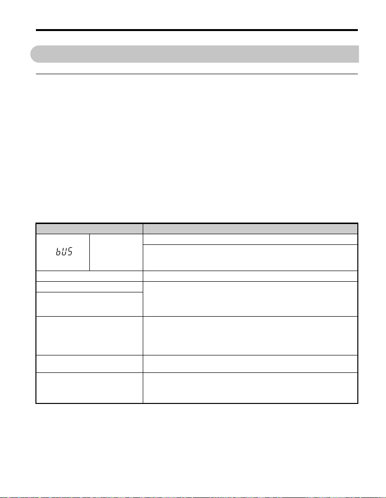
9 異常診断とその対策
9 異常診断とその対策
◆ インバータ側で表示される異常コード
オプションカードに関連するエラーを表 7 に掲載しています。以下に掲載されていない
場合は,オプションカードを取付けたインバータの取扱説明書を参照してください。
■ 異常
bUS(オプションカード通信異常)と EF0(通信オプションからの外部異常入力)は,
異常と軽故障の 2 種類の表示があります。異常の発生時は,LED オペレータに表示さ
れる文字は「点滅」ではなく「点灯」します。(ALM ランプも点灯します。)点滅表示
される場合は,「軽故障・警告」です。
インバータにアラームが表示される場合,最初に以下の点について確認してください。
•LONWORKS通信ケーブルは確実にオプションカードに接続されているか。
• オプションカードはインバータに確実に接続されているか。
• 瞬時停電などにより,データ通信が途絶えることがないか。
表 7 異常表示と対策
オペレータ表示 異常名
オプションカード通信異常
bUS
原因 対策
上位装置から通信指令が来ない
通信ケーブルの配線が正しくな
い,または短絡や断線が発生して
いる
ノイズの影響で通信データに異常
が発生している
オプションカードが破損している
通信タイムオーバ
通信エラーを検出した
(運転指令または周波数指令を,「オプションカードから設定(b1-03
= 3 または b1-02 = 3)」と選択しているとき)
配線ミスがないかを確認する。
⇒配線を正しく行う。
⇒地絡または断線している個所を取り除く。
⇒制御回路の配線,主回路の配線,接地配線を確認し,十分なノイ
ズ対策を行う。
⇒電磁接触器がノイズ発生源であれば,電磁接触器のコイルにサー
ジアブソーバを接続する。
⇒通信ケーブルを LONWORKS 専用品に変更する。
⇒配線に異常がなく,常時異常が発生する場合は,オプションカー
ドを交換する。
レシーブハートビート設定時間内に定められたデータが受信できな
かった。
⇒レシーブハートビート設定時間を確認する。
⇒通信機器,通信信号をチェックする。
㈱安川電機 TOBP C730600 56A 1000シリーズオプション SI-W3 取扱説明書 33
Page 74

9 異常診断とその対策
オペレータ表示 異常名
EF0
原因 対策
上位装置から通信データで外部異
常が入力(送信)された
上位プログラムの異常 ⇒上位プログラムの動作チェックを行い,適切に修正する。
ネットワークからの設定が正しくない⇒ネットワークのプログラムを確認したうえで設定を修正してくだ
オペレータ表示 異常名
oFA00
原因 対策
CN5-A に対応していないオプ
ションカードを接続した
オペレータ表示 異常名
oFA01
原因 対策
インバータとオプションカード間
のコネクタ接続が正しくない
オペレータ表示 異常名
〜
oFA30〜 oFA43
通信オプションカードからの外部異常入力
外部機器のアラーム機能が動作している
⇒外部異常の原因を取り除く。
⇒上位装置の外部異常入力を解除する。
さい。
オプションカード異常 (CN5-A)
未対応オプションカード接続
⇒オプションを正しく接続する。
本オプションカードを CN5-A に接続してください。
その他のオプションカードについては,各オプションカードの取扱
説明書を参照してください。
オプションカード異常 (CN5-A)
オプションカード接続不良
⇒電源を OFF にして,オプションカードをインバータのコネクタに
正しく接続する。
オプションカード異常(CN5-A)
オプションカードのハードウェア不良
原因 対策
オプションカードのハードウェア異常⇒オプションカードを交換する。(詳細は当社にお問い合わせくださ
オペレータ表示 異常名
oFb00
原因 対策
CN5-B に対応していないオプ
ションカードを接続した
34 ㈱安川電機 TOBP C730600 56A 1000 シリーズオプション SI-W3 取扱説明書
い。)
オプションカード異常 (CN5-B)
未対応オプションカード
⇒オプションを正しく接続する。
本オプションカードを CN5-A に接続してください。
その他のオプションカードについては,各オプションカードの取扱
説明書を参照してください。
Page 75

9 異常診断とその対策
オペレータ表示 異常名
oFb02
原因 対策
CN5-A に本オプションカードを
接続し,CN5-B に通信オプショ
ン (SI-)
A3 を接続した
CN5-C に対応していないオプ
ションカードを接続した
CN5-A に本オプションカードを
接続し,CN5-C に通信オプショ
ン (SI-)
A3 を接続した
,AI-A3,または DI-
オペレータ表示 異常名
oFc00
原因 対策
オペレータ表示 異常名
oFc02
原因 対策
,AI-A3,または DI-
■ 軽故障・警告
オペレータ表示 軽故障名
CALL
原因 対策
通信ケーブルや終端抵抗の配線が
正しくない,または短絡や断線が
発生している
ネットワークの設定異常 ⇒通信開始時の動作を確認し,原因個所を修正する。
通信回路が破損している
オプションカード異常 (CN5-B)
同種オプション接続
⇒ SI-・AI-A3・DI-A3 はいずれか 1 枚しか取付けられません。本
オプションカードを CN5-A に接続してください。
オプションカード異常 (CN5-C)
未対応オプションカード
⇒オプションを正しく接続する。
本オプションカードを CN5-A に接続してください。
その他のオプションカードについては,各オプションカードの取扱
説明書を参照してください。
オプションカード異常 (CN5-C)
同種オプション接続
⇒ SI-・AI-A3・DI-A3 はいずれか 1 枚しか取付けられません。本
オプションカードを CN5-A に接続してください。
通信待機中
ネットワークから制御データを正常受信できない。
配線ミスがないかを確認する。
⇒配線を正しく行う。
⇒地絡または断線している個所を取り除く。
電源を再投入する。
⇒再度「CALL」を検出する場合は,オプションカー
ドを交換する。
軽故障出力
(H2-=10)
有り
㈱安川電機 TOBP C730600 56A 1000シリーズオプション SI-W3 取扱説明書 35
Page 76

10 仕様と保証について
10 仕様と保証について
◆ 仕様
表 8 オプションカードの仕様
形式
ノードタイプ ホストアプリケーションノード
通信速度
通信用 IC
通信ドライバ
通信プロトコル
ネットワーク変数
エイリアスネットワーク変数
最大接続台数
総配線長
周囲温度
周囲湿度
保存温度
設置場所 室内(腐食性ガス,じんあいなどのない所)
標高
SI-W3
78 kbps
ニューロンチップ FT3120
FT-X1(フリートポロジー)
LonTalk プロトコル準拠
総数 236 個
標準 (SNVT):Variable Speed Motor Drive function profile Ver1.1 準拠
最大 50 個
64 台(同一セグメント内)
最大 500 m
–10°C 〜 +50°C
95% RH 以下(ただし結露しないこと)
–20°C 〜 +60°C(輸送中の短期間温度)
1000 m 以下
36 ㈱安川電機 TOBP C730600 56A 1000 シリーズオプション SI-W3 取扱説明書
Page 77

10 仕様と保証について
◆ 保証について
■ 無償保証期間と保証範囲
無償保証期間
貴社または貴社顧客殿に引き渡し後 1 年未満,または当社工場出荷後 18 か月以内のう
ちいずれか早く到達した期間。
保証範囲
故障診断
一次故障診断は,原則として貴社にて実施をお願い致します。
ただし,貴社要請により当社または当社サービス網がこの業務を有償にて代行すること
ができます。
この場合,貴社との協議の結果,故障原因が当社側にある場合は無償とします。
故障修理
故障発生に対して,製品の故障を修復させるための修理,代品交換,現地出張は無償と
します。ただし,次の場合は有償となります。
• 貴社及び貴社顧客など貴社側における不適切な保管や取扱い,不注意過失及び貴社
側の設計内容などの事由による故障の場合。
• 貴社側にて当社の了解なく当社製品に改造など手を加えたことに起因する故障の場
合。
• 当社製品の仕様範囲外で使用したことに起因する故障の場合。
• 天災や火災など不可抗力による故障の場合。
• 無償保証期間を過ぎた場合。
• 消耗品及び寿命品の補充交換の場合。
• 梱包・くん蒸処理に起因する製品不良の場合。
• その他,当社の責に帰さない事由による故障の場合。
上記サービスは国内における対応とし,国外における故障診断などはご容赦願います。
ただし,海外でのアフターサービスをご希望の場合には有償での海外サービス契約をご
利用ください。
■ 保証責務の除外
無償保証期間内外を問わず,当社製品の故障に起因する貴社あるいは貴社顧客など,貴
社側での機会損失ならびに当社製品以外への損傷,その他業務に対する補償は当社の保
証外とさせていただきます。
■ 本製品の適用について
• 本製品は,人命にかかわるような状況の下で使用される機器あるいはシステムに用
いられることを目的として設計,製造されたものではありません。
㈱安川電機 TOBP C730600 56A 1000シリーズオプション SI-W3 取扱説明書 37
Page 78

10 仕様と保証について
• 本製品を,乗用移動体用,医療用,航空宇宙用,原子力用,電力用,海底中継用の
機器あるいはシステムなど,特殊用途への適用をご検討の際には,当社の営業窓口
までご照会ください。
• 本製品は厳重な品質管理の下に製造しておりますが,本製品の故障により重大な事
故または損失の発生が予測される設備への適用に際しては,安全装置を設置してく
ださい。
38 ㈱安川電機 TOBP C730600 56A 1000 シリーズオプション SI-W3 取扱説明書
Page 79

10 仕様と保証について
QSG_only
◆ 改版履歴
資料の改版についての情報は,本資料の裏表紙の右下に資料番号と共に記載していま
す。
資料番号 TOBP C730600 56A
2011 年11 月 作成 11-11
C
発行年/月
2011年 11 月
発行年月
初版発行年月
改版
番号
−−
項番号 変更点
初版発行
㈱安川電機 TOBP C730600 56A 1000シリーズオプション SI-W3 取扱説明書 39
Page 80

安川インバータ 1000シリーズオプション
LONWORKS
通信
取扱説明書
技術的なお問い合わせ相談窓口(YASKAWAコールセンタ)
●インバータ
TEL
0120-114-616 0120-114-537
[月〜金(祝祭日及び当社休業日は除く)/9:00〜12:00, 13:00〜17:00]※FAXは24時間受け付けております。
製造・販売
株式会社
安川電機 URL: http://www.yaskawa.co.jp/
販 売
東京支社 TEL (03)5402-4503 FAX (03)5402-4508 東京都港区海岸1丁目16番1号ニューピア竹芝サウスタワー8階〒105-6891
名古屋支店
TEL (052)581-2251 FAX (052)581-2274 名古屋市中村区名駅3丁目25番9号堀内ビル9階〒450-0002
大阪支店 TEL (06)6346-4512 FAX (06)6346-4556 大阪市北区堂島2丁目4番27号新藤田ビル4階〒530-0003
九州支店 TEL (092)714-5906 FAX (092)761-5136 福岡市中央区天神4丁目1番1号第7明星ビル7階〒810-0001
●
各地区の営業所,出張所は
http://www.e-mechatronics.com/
周辺機器・ケーブル・部品
の「セールスネットワーク」でご確認ください。
FAX
安川コントロール株式会社 URL: http://www.yaskawa-control.co.jp/
東部営業部
TEL (03)3263-5611 FAX (03)3263-5625 東京都千代田区飯田橋1-3-2 曙杉館ビル6階 〒102-0072
西部営業部
TEL (06)6337-8102 FAX (06)6337-4513 大阪府吹田市豊津町12-24 中村ビル2階 〒564-0051
九州営業部
TEL (0930)24-8630 FAX (0930)24-8637 行橋市西宮市2-13-1 (株)安川電機行橋事業所内〒824-8511
●
技術相談テレホンサービス TEL 0120-854388
[月〜金(祝祭日及び当社休業日は除く)/9:00〜12:00, 13: 00〜17:00]
アフターサービス
安川エンジニアリング株式会社 URL: http://www.yaskawa-eng.co.jp/top.html
関東支店 TEL (04)2931-1819 (夜間(04)2931-1818) FAX (04)2931-1811
埼玉県入間市大字新光142-3 〒358-0055
名古屋支店
TEL (052)331-5318 (夜間(052)331-5380) FAX (052)331-5374
名古屋市中区千代田4-1-6 第৻国枝ビル 〒460-0012
関西支店 TEL (06)6378-6526 (夜間(06)6378-6533) FAX (06)6378-6531
大阪府摂津市千里丘7-10-37 〒566-0001
九州支店 TEL (093)663-5105 (夜間(093)663-5108) FAX (093)288-4432
北九州市八幡東区前田北洞岡2-3 新日鐵八幡製鐵所敷地内〒805-0058
本製品の最終使用者が軍事関係であったり,用途が兵器などの製造用である場合には,「外国為替
及び外国貿易法」の定める輸出規制の対象となることがありますので,輸出される際には十分な
審査及び必要な輸出手続きをお取りください。
株式会社
安川電機
製品改良のため,定格,仕様,寸法などの一部を予告なしに変更することがあります。
この資料の内容についてのお問い合わせは,当社代理店もしくは,上記の営業部門にお尋ねくだ
さい。
資料番号
© 2011年11
10-10-3
無断転載・複製を禁止
TOBP C730600 56A
作成
月
11-11
 Loading...