

Page 1

AC Servomotors and Driver
SGMM Servomotor
SGDF Servopack
YASKAWA
YA S K A WA
MANUAL NO. SIE-S800-27C
Page 2
Safety Information
The following conventions are used to indicate precautions in this manual. Failure to heed precautions pro-
vided in this manual may result in serious or possibly even fatal injury or damage to the products or to re-
lated equipment and systems.
WARNING
Indicates precautions that, if not heeded, could result in loss of life or serious injury.
CAUTION
Indicates precautions that, if not heeded, could result in relatively serious or minor injury, damage to the
product, or faulty operations.
In some instances, items described in
CAUTION
may also result in a serious accident.
— iii —
Page 3

Visual Aids
The following aids are used to indicate certain types of information for easier reference.
.
Indicates references for additional information.
TERMS
Speed/Torque
Positions
Indicates definitions of difficult terms that have not been previously explained in
this manual.
Indicates information that is applicable only to Servopacks for speed/torque control (Model SGDF-jjCS).
If neither this icon nor the following icon appears, the description is applicable to
both types of Servopack.
Indicates information that is applicable only to Servopacks for position control
(Model SGDF-jjCP).
If neither this icon nor the previous icon appears, the description is applicable to
both types of Servopack.
Indicates information explaining the operating procedure using Hand-held Digital
Operator (Model JUSP-OP02A-3).
—iv—
Page 4

CONTENTS
Safety Precautions xi...................................................
CHAPTER 1 BASIC OPERATION 1-1..................................
1.1 Precautions 1-2.............................................................
1.2 Installation 1-4.............................................................
1.2.1 Checking on Delivery 1-4..............................................
1.2.2 Installing the Servomotor 1-6...........................................
1.2.3 Installing the Servopack 1-9............................................
1.2.4 Power Loss 1-11......................................................
1.3 Connection and Wiring 1-12....................................................
1.3.1 Connecting to Peripheral Devices 1-12....................................
1.3.2 Main Circuit Wiring and Power ON Sequence 1-14..........................
1.3.3 Examples of Connecting Host Controllers 1-16..............................
1.4 Conducting a Test Run 1-23....................................................
1.4.1 Test Run in Two Steps 1-23.............................................
1.4.2 Step 1: Test Run for Servomotor without Load 1-24..........................
1.4.3 Step 2: Test Run with the Servomotor Connected to the Machine 1-28............
1.4.4 Supplementary Information on Test Run 1-29...............................
1.4.5 Minimum Parameters and Input Signals 1-30...............................
CHAPTER 2 APPLICATIONS 2-1......................................
2.1 Setting Parameters According to Machine Characteristics 2-4.........................
2.1.1 Changing Motor Rotation Direction 2-4...................................
2.1.2 Torque Limit 2-5.....................................................
2.2 Setting Parameters According to Host Controller 2-9...............................
2.2.1 Speed References 2-9.................................................
2.2.2 Position References 2-13...............................................
2.2.3 Encoder Output 2-17..................................................
2.2.4 Contact I/O 2-21......................................................
2.2.5 Electronic Gear 2-24...................................................
2.2.6 Contact Input Speed Control 2-28........................................
2.2.7 Torque Control 2-32...................................................
2.2.8 Reference Pulse Inhibit Function (INHIBIT) 2-36............................
2.2.9 Reference Pulse Input Filter Selection Function 2-37.........................
2.3 Setting Up the Σ-Series Servopack 2-38...........................................
2.3.1 Parameters 2-38......................................................
2.3.2 Jog Speed 2-39.......................................................
2.4 Setting Stop Mode 2-40.......................................................
2.4.1 Offset Adjustment 2-40................................................
2.4.2 Zero-clamp 2-41......................................................
2.4.3 Holding Brake 2-43...................................................
2.5 Running the Motor Smoothly 2-46...............................................
2.5.1 Soft Start Function 2-46................................................
2.5.2 Smoothing 2-47......................................................
—v—
Page 5

CONTENTS
2.5.3 Gain Adjustment 2-47.................................................
2.5.4 Offset Adjustment 2-48................................................
2.5.5 Torque Reference Filter Time Constant 2-48................................
2.6 Minimizing Positioning Time 2-49...............................................
2.6.1 Autotuning 2-49......................................................
2.6.2 Servo Gain 2-49......................................................
2.6.3 Feed-forward Control 2-51..............................................
2.6.4 Proportional Control 2-51...............................................
2.6.5 Setting Speed Bias 2-52................................................
2.6.6 Mode Switch 2-53....................................................
2.6.7 Speed Loop Compensation 2-58..........................................
2.7 Designing a Protective Sequence 2-60............................................
2.7.1 Servo Alarm Output 2-60...............................................
2.7.2 Servo ON Input Signal 2-62.............................................
2.7.3 Positioning Complete Output 2-63........................................
2.7.4 Speed Coincidence Output 2-64..........................................
2.7.5 Running Output Signal 2-65.............................................
2.8 Special Wiring 2-67..........................................................
2.8.1 Wiring Precautions 2-67................................................
2.8.2 Wiring for Noise Control 2-69...........................................
2.8.3 Using More Than One Servo Drive 2-73...................................
2.8.4 Connector Terminal Layouts 2-74........................................
CHAPTER 3 USING THE DIGITAL OPERATOR 3-1.....................
3.1 Basic Operations 3-2.........................................................
3.1.1 Connecting the Digital Operator 3-2.....................................
3.1.2 Resetting Servo Alarms 3-3............................................
3.1.3 Basic Functins and Mode Selection 3-4...................................
3.1.4 Operation in Status Display Mode 3-5....................................
3.1.5 Operation in Parameter Setting Mode 3-7.................................
3.1.6 Operation in Monitor Mode 3-9.........................................
3.2 Applications 3-13............................................................
3.2.1 Operation in Alarm Traceback Mode 3-13..................................
3.2.2 Operation Using the Digital Operator 3-15.................................
3.2.3 Autotuning 3-16......................................................
3.2.4 Reference Offset Automatic Adjustment 3-21...............................
3.2.5 Reference Offset Manual Adjustment 3-22.................................
3.2.6 Clearing Alarm Traceback Data 3-25......................................
3.2.7 Checking Motor Type 3-26..............................................
3.2.8 Checking Software Version 3-26.........................................
CHAPTER 4 SERVO SELECTION AND DATA SHEETS 4-1...............
4.1 Selecting a Servo Drive 4-3...................................................
4.1.1 Selecting a Servomotor 4-3............................................
—vi—
Page 6

CONTENTS
4.1.2 Selecting a Servopack 4-9.............................................
4.2 Servomotor Ratings and Characteristics 4-11.......................................
4.2.1 Ratings and Specifications 4-11..........................................
4.2.2 Mechanical Characteristics 4-16..........................................
4.3 Servopack Ratings and Characteristics 4-18........................................
4.3.1 Ratings and Specifications 4-18..........................................
4.3.2 Overload Characteristics 4-25...........................................
4.3.3 Starting Time and Stopping Time 4-26.....................................
4.3.4 Overhanging Loads 4-26...............................................
4.3.5 In-rush Current and Power Loss 4-27......................................
4.4 Servo Drive Dimensional Drawings 4-28..........................................
4.4.1 Servomotor Dimensional Drawings 4-28...................................
4.4.2 Servomotor Dimensional Drawings: European Safety Standards 4-37............
4.4.3 Servopack Dimensional Drawings 4-45....................................
4.4.4 Digital Operator Dimensional Drawings 4-46...............................
4.5 Selecting Peripheral Devices 4-47...............................................
4.5.1 Selecting Peripheral Devices 4-47........................................
4.6 Specifications and Dimensional Drawings of Peripheral Devices 4-50...................
4.6.1 Cable Specifications and Peripheral Devices 4-50............................
4.6.2 Motor Cables 4-51....................................................
4.6.3 Encoder Cables 4-54...................................................
4.6.4 Connector Kits 4-56...................................................
4.6.5 Cable with CN1 Connector at One End Only 4-61...........................
4.6.6 Circuit Breaker 4-61...................................................
4.6.7 Noise Filter 4-62......................................................
4.6.8 Magnetic Contactor 4-62...............................................
4.6.9 Surge Suppressor 4-64.................................................
4.6.10 Variable Resistor for Speed Setting 4-64...................................
4.6.11 Encoder Signal Converter Unit 4-65......................................
4.6.12 Cables for Connecting PC and Servopack 4-67..............................
CHAPTER 5 INSPECTION AND MAINTENANCE 5-1....................
5.1 Servo Drive Inspection and Maintenance 5-2......................................
5.1.1 Servomotors 5-2.....................................................
5.1.2 Servopack 5-3.......................................................
5.2 Error Diagnosis and Troubleshooting 5-4.........................................
5.2.1 Troubleshooting Problems with Alarm Display 5-4..........................
5.2.2 Troubleshooting Problems With No Alarm Display 5-13......................
5.2.3 Servopack Connection Diagrams 5-15.....................................
CHAPTER 6 EMC DIRECTIVE MEASURES 6-1.........................
6.1 Servo Drive Inspection and Maintenance 6-2......................................
6.1.1 What are EN Standards? 6-2............................................
6.1.2 What is the CE Marking? 6-2...........................................
— vii —
Page 7

CONTENTS
6.1.3 EMC Directive 6-2...................................................
6.1.4 TÜV Certification Body Authorized by EU 6-3.............................
6.2 Measures to Satisfy the EMC Directive 6-4.......................................
6.2.1 Applicable Servomotors 6-4............................................
6.2.2 Applicable Noise Filter 6-4............................................
6.2.3 Applicable Power Supply 6-4...........................................
6.2.4 Motor Cables 6-4....................................................
6.2.5 Encoder Cables 6-5...................................................
6.2.6 Control I/O 6-7......................................................
6.2.7 Digital Operator and Monitoring by Personal Computer 6-7...................
6.2.8 Cable Core 6-7......................................................
6.2.9 Wiring Examples 6-8.................................................
APPENDICES
A Servo Adjustment A-1........................................................
A.1 Σ-Series AC Servopack Gain Adjustment A-2......................................
A.1.1 Σ-Series AC Servopacks and Gain Adjustment Methods A-2..................
A.1.2 Basic Rules for Gain Adjustment A-3.....................................
A.2 Adjusting a Speed-control Servopack A-4..........................................
A.2.1 Adjusting Using Autotuning A-4........................................
A.2.2 Manual Adjustment A-5...............................................
A.3 Adjusting a Position-control Servopack A-8........................................
A.3.1 Adjusting Using Autotuning A-8........................................
A.3.2 Manual Adjustment A-9...............................................
A.4 Gain Setting References A-13....................................................
A.4.1 Guidelines for Gain Settings According to Load Inertia Ratio A-13..............
B List of I/O Signals B-1........................................................
C List of Parameters C-1........................................................
D List of Alarm Displays D-1....................................................
INDEX Index 1...........................................................
— viii —
Page 8

Overview
About this Manual
This manual provides the following information for users of Σ-Series Servomotors and Servo Drives.
• An overview of Servo Systems for first-time users.
• Checking the product on delivery and basic applications of the Servo.
• Servo applications.
• Selecting an appropriate Servo for your needs and placing an order.
• Inspection and maintenance.
Using this Manual
Manual Structure
All chapters in this manual are classified into one or more of three areas according to their contents: A, B,
and C. Refer to the applicable chapters for the information required.
A: Chapters explaining how to select a Servo: For users who wish to gain a basic understanding of
Σ-Series products or who need to select an appropriate Servo.
B:
Chapters explaining how to design a Servo System: For users who intend to design, install, and operate a Σ-Series Servo Control System.
C: Chapters explaining maintenance: For users who are going to maintain and troubleshoot Σ-Series
products.
Chapter
CHAPTER 1 Basic Operation 1-1 B........................................ .........
CHAPTER 2 Applications 2-1 B........................................... .........
CHAPTER 3 Using the Digital Operator
CHAPTER 4 Servo Selection and Data Sheets 4-1 A, B........................ .........
CHAPTER 5 Inspection and Maintenance 5-1 C............................ .........
CHAPTER 6 EMC Directive Measures
APPENDICES
Title Page Area
Describes steps to take when product is received, plus basic
wiring and application methods.
Describes the effective usage of Σ-Series features according
to application.
.............................. .........
Describes operating procedures for Σ-Series Servos, turning
features ON and OFF, setting control constants, etc.
Describes selection methods for Σ-Series Servos and peripherals and provides Servo specifications.
Describes user maintenance and troubleshooting.
................................ .........
Provides the measures to conform to EN standards.
A
Servo Adjustment A-1
B List of I/O Signals B-1 A, B, C....................................... ........
C List of Parameters C-1 B, C....................................... ........
D List of Alarm Displays D-1 B, C.................................... ........
....................................... ........
3-1
6-1
B
B
B, C
INDEX
.............................................................. ....
Index 1
—ix—
A, B, C
Page 9

BASIC USES OF Σ-SERIES PRODUCTS
Basic Terms
Meaning of Basic Terms
Unless otherwise specified, the following definitions are used in this manual.
Servomotor: Σ-Series SGMM Servomotor.
Servopack: Σ-Series SGDF Servopack.
Servo Drive: A set including an SGMM/SGDF Servomotor and an SGDF Servopack
Servo System: A complete Servo control system consisting of Servo Drive, host controller, and
peripheral devices.
Description of Technical Terms
Technical terminology that appears as bold in text is explained briefly at the bottom of the page.
—x—
Page 10
Safety Precautions
The following precautions are for checking products upon delivery, installation, wiring, operation,
maintenance and inspections.
Checking Products upon Delivery
J
D Always use the Servomotor and Servopack in one of the specified combinations.
Not doing so may cause fire or malfunction.
Installation
J
D Never use the products in an environment subject to water, corrosive gases, inflammable gases,
or combustibles
Doing so may result in electric shock or fire.
!
CAUTION
!
CAUTION
Wiring
J
!
WARNING
D Ground the equipment ground terminal according to electrical codes (ground resistance: 100 Ω or
less).
Improper grounding may result in electric shock or fire.
!
CAUTION
D Do not connect a three-phase power supply to the U, V, or W output terminals.
Doing so may result in injury or fire.
D Securely fasten the power supply terminal screws and motor output terminal screws.
Not doing so may result in fire.
—xi—
Page 11

BASIC USES OF Σ-SERIES PRODUCTS
Operation
J
D Never touch any rotating motor parts while the motor is running.
Doing so may result in injury.
D Conduct trial operation on the Servomotor alone with the motor shaft disconnected from machine
to avoid any unexpected accidents.
Not doing so may result in injury.
D Before starting operation with a machine connected, change the settings to match the user’s
constants of the machine.
Starting operation without matching the proper settings may cause the machine to run out of control or malfunction.
!
WARNING
!
CAUTION
D Before starting operation with a machine connected, make sure that an emergency stop can be
applied at any time.
Not doing so may result in injury.
D Do not touch the heat sinks during operation.
Doing so may result in burns due to high temperatures.
Maintenance and Inspection
J
!
WARNING
D Never touch the inside of the Servopacks.
Doing so may result in electric shock.
D Do not touch terminals for five minutes after the power is turned OFF.
Residual voltage may cause electric shock.
!
CAUTION
D Do not disassemble the Servomotor.
Doing so may result in electric shock or injury.
D Do not attempt to change wiring while the power is ON.
Doing so may result in electric shock or injury.
— xii —
Page 12

General Precautions
J
Note the following to ensure safe application.
S The drawings presented in this manual are sometimes shown without covers or protective
guards. Always replace the cover or protective guard as specified first, and then operate the
products in accordance with the manual.
S The drawings presented in this manual are typical examples and may not match the product you
received.
S This manual is subject to change due to product improvement, specification modification, and
manual improvement. When this manual is revised, the manual code is updated and the new
manual is published as a next edition. The edition number appears on the front and back covers.
S If the manual must be ordered due to loss or damage, inform your nearest Yaskawa representa-
tive or one of the offices listed on the back of this manual.
S Yaskawa will not take responsibility for the results of unauthorized modifications of this prod-
uct. Yaskawa shall not be liable for any damages or troubles resulting from unauthorized modification.
— xiii —
Page 13

BASIC USES OF Σ-SERIES PRODUCTS
Yaskawa, 1999
All rights reserved. No part of this publication may be reproduced, stored in a retrieval system, or transmitted, in any form,
or by any means, mechanical, electronic, photocopying, recording, or otherwise, without the prior written permission of
Yaskawa. No patent liability is assumed with respect to the use of the information contained herein. Moreover, because
Yaskawa is constantly striving to improve its high-quality products, the information contained in this manual is subject to
change without notice. Every precaution has been taken in the preparation of this manual. Nevertheless, Yaskawa assumes no responsibility for errors or omissions. Neither is any liability assumed for damages resulting from the use of the
information contained in this publication.
— xiv —
Page 14

BASIC OPERATION
This chapter describes the initial procedures when Σ-Series products are delivered. It also explains the basic methods of connecting and operating Σ-Se-
ries products. Both first-time and experienced servo users
chapter.
1.1 Precautions 1-2...............................
1.2 Installation 1-4...............................
1.2.1 Checking on Delivery 1-4................................
1.2.2 Installing the Servomotor 1-6.............................
1.2.3 Installing the Servopack 1-9..............................
1.2.4 Power Loss 1-11........................................
1
must read
1
this
1.3 Connection and Wiring 1-12.....................
1.3.1 Connecting to Peripheral Devices 1-12......................
1.3.2 Main Circuit Wiring and Power ON Sequence 1-14............
1.3.3 Examples of Connecting Host Controllers 1-16................
1.4 Conducting a Test Run 1-23.....................
1.4.1 Test Run in Two Steps 1-23...............................
1.4.2 Step 1: Test Run for Servomotor without Load 1-24............
1.4.3 Step 2: Test Run with the Servomotor Connected to
the Machine 1-28........................................
1.4.4 Supplementary Information on Test Run 1-29.................
1.4.5 Minimum Parameters and Input Signals 1-30..................
— 1-1 —
Page 15
BASIC OPERATION
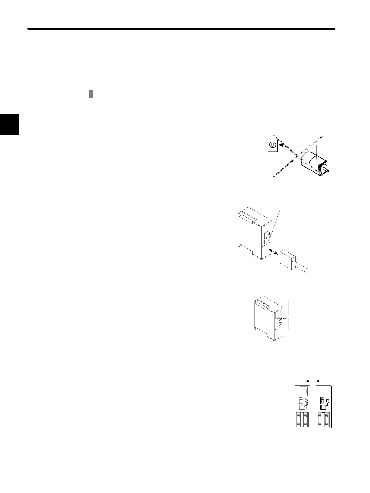
1.1 Precautions
This section provides precautions that must be observed when using Σ-Series products.
1
Do not connect the Servomotor directly to a commercial power supply.
Do not plug the Servomotor directly into the commercial power supply. Direct connection to the
Do not connect
directly.
commercial power supply will damage the Servomotor. The Servomotor cannot operate without a
Servopack.
200 V or
100 V power
supply
Damage will result!
Do not connect or disconnect the connector when power is ON.
Always turn the power OFF before connecting or
Not lit
disconnecting a connector, except for the connector for the Digital Operator.
Always turn OFF
the power before
connecting or
disconnecting a
connector.
Do not perform inspection or maintenance work for at least 5 minutes after the
power is turned OFF.
Even after the power is turned OFF, residual voltage still remains in the capacitor inside the Servopack. If inspection is to be performed after the
power is turned OFF, always wait at least 5 min-
Careful!
Residual
voltage remains
in capacitor
utes to avoid the risk of an electrical shock.
Wait at least 5
minutes
Install the Servopack at least 10 mm from other devices.
The Servopack generates heat. Configure the
system layout so that the Servopack is located
where it can radiate heat freely. The Servopack
must be installed in an environment free from condensation, vibration, and shock.
— 1-2 —
Ambient
temperature:
0to50°C
Provide sufficient
clearance.
10 mm
Page 16

Perform noise reduction and grounding properly.
1.1Precautions
If the signal line is noisy, vibration or malfunction
will result.
Install the system according to the following pre-
Casing
Servopack
Signal
line
cautions.
D Separate high-voltage cables from low-voltage cables.
D Use cables as short as possible.
D Be sure to ground (ground resistance 100 Ω or
less) for the Servomotor and Servopack.
D Never use a noise filter for the power supply
between the Servomotor and Servopack.
Do not perform continuous operation under overhanging load.
Continuous operation cannot be performed by rotating the motor from the load and applying regenerative braking. Regenerative braking by the Servopack can be applied only for a short period,
such as when the motor is stopped.
Do not apply regenerative
braking continuously.
Do not operate the Servomotor by turning the power ON and OFF.
Servomotor
Be sure to ground
(less than 100 Ω).
Servomotor
1
Frequently turning the power ON and OFF causes
the internal circuit elements to deteriorate. Always
start or stop the Servomotor by using reference
pulses.
Servopack
Power
supply
Do not start and stop by
turning power ON and OFF
— 1-3 —
Page 17

1
BASIC OPERATION
1.2.1 Checking on Delivery
1.2 Installation
This section describes how to check Σ-Series products on delivery and how to install
them.
1.2.1 Checking on Delivery
When Σ-Series products are delivered, check the following items.
Check Items
Check if the delivered products are
the ones you ordered.
Check if the motor shaft rotates
smoothly.
Check for damage. Check the overall appearance, and check for damage
Check screws for looseness. Check for looseness by using a screwdriver.
If any of the above items are faulty or incorrect, contact the dealer from which you purchased the products or your Yaskawa representative.
Check the types marked on the nameplates of
Servomotor and Servopack (see the following table).
If the motor shaft is smoothly turned by hand, it is
normal. If the motor has brakes, however, it cannot be
turned manually.
or scratches resulting from transportation.
Remarks
— 1-4 —
Page 18
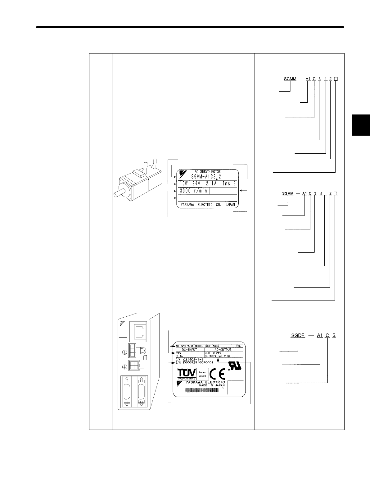
Servomotors
Appearance Nameplate Type
Standard Servomotors
Σ-Series
SGMM Servomotor
Rated output
A1: 10 W B3: 3 W
A2: 20 W B5: 5 W
A3: 30 W B9: 10 W
Supply voltage
B: 100 VAC
C: 24 VDC
S: EC safety standards, 24 VDC
(10 W, 20 W)
Encoder specifications
3: 2048 P/R incremental encoder
F: 1024 P/R incremental encoder
Design revision order
Shaft specifications
2: Straight without key
3: Straight with flat seat
Option
C: With brake (24 VDC)
Servomotors with Reduction Gears
Σ-Series
SGMM Servomotor
Rated output
A1: 10 W
A2: 20 W
A3: 30 W
Supply voltage
B: 100 VAC
C: 24 VDC
S: EC safety standards, 24 VDC
(10 W, 20 W)
Encoder specifications
3: 2048 P/R incremental encoder
With reduction gears
Gear ratio
A: 1.5 1: 1/5
B: 1/16 2: 1/16
C: 1/25 3: 1/25
(10/20 W) (30 W)
Shaft specifications
2: Straight without key
6: Straight with key and tap
Option
C: With brake (24 VDC)
Σ-Series
SGMM Servomotor
Rated output
Servomotor model
G89526−1−1−10
Serial number
Rated speed
Manufacturing
date
Rated output
current
98/8
1.2Installation
1
A
Servopacks
SGDFA1CS
DC24V
SERVOPACK
CN3
RDY
ALM
CN4
CN2/PG
CN1/IO
Σ-Series SGDF
Servopack
C
N
5
Applicable power supply
Servopack model
Serial number
Applicable
motor capacity
Σ-Series
SGDF Servopack
Rated output
A1: 10 W B3: 3 W
A2: 20 W B5: 5 W
A3: 30 W B9: 10 W
Supply voltage
C: 24 VDC
Type
S: For speed/torque control
P: For position control
— 1-5 —
Page 19
1
BASIC OPERATION
1.2.2 Installing the Servomotor
1.2.2 Installing the Servomotor
Servomotors can be installed either horizontally or vertically. If, however, the Servomotor is
installed incorrectly or in an inappropriate location, the service life will be shortened or unexpected problems will occur. To prevent this, always follow the installation instructions described below and install properly.
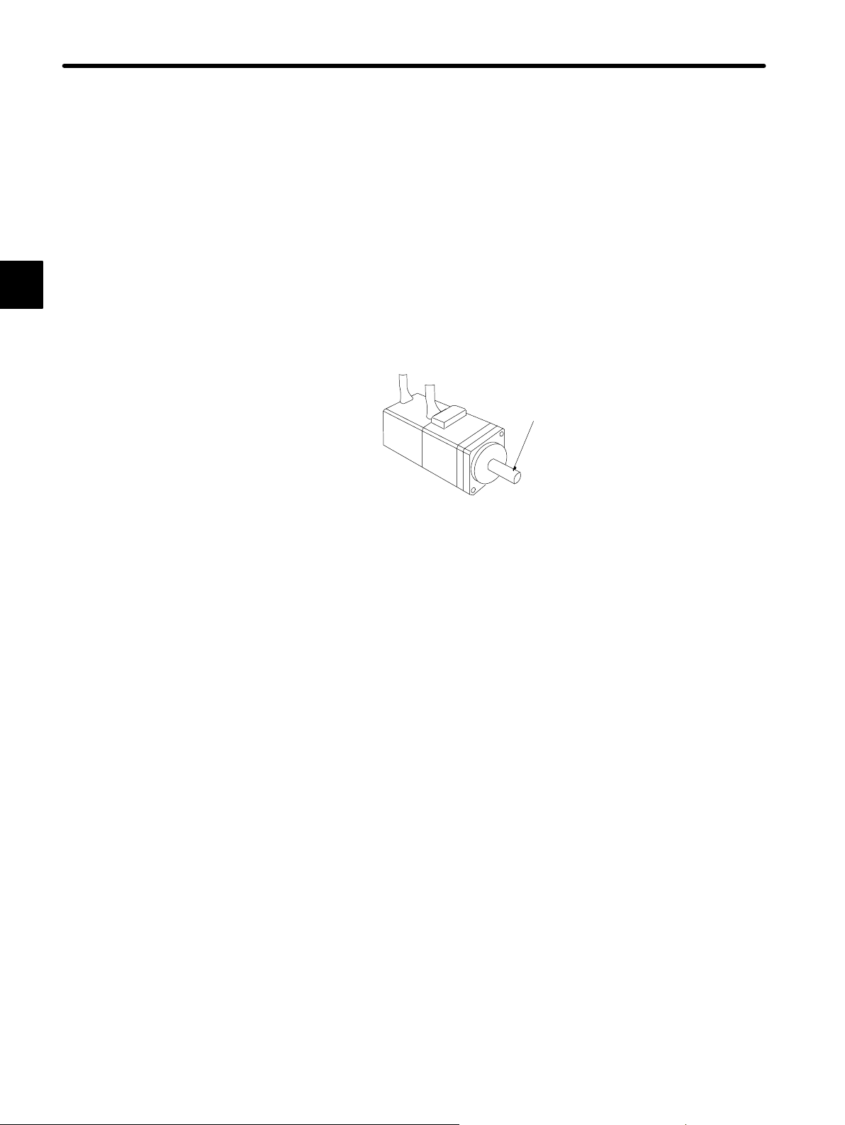
Before Installation
The edge of the motor shaft has an anticorrosive coating. Carefully and thoroughly clean
off the anti-corrosive coating using a cloth moistened with thinner before installing the
motor. Make sure that the thinner is completely wiped off.
Anticorrosive coating
Do not get thinner on any other parts of the Servomotor when cleaning the shaft.
Note
Storage Temperature
When the Servomotor is to be stored with the power cable disconnected, store it within
the following temperature range.
Between −20 and 60°C
Installation Site
The Servomotors are designed for indoor use.
Install the Servomotor in an environment which meets the following conditions:
Free from corrosive and explosive gases
•
Well-ventilated and free from dust and moisture
•
Ambient temperature of 0°Cto40°C
•
Relative humidity of 20% to 80% (with no condensation)
•
Inspection and cleaning can be performed easily
•
If the Servomotor is used in a location subject to water or oil mist, install a shield cover
over the Servomotor to prevent water or oil mist from entering the Servomotor.
— 1-6 —
Page 20
1.2Installation
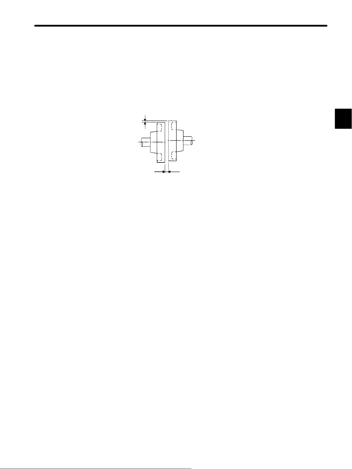
Alignment
Align the shaft of the Servomotor with that of the equipment to be controlled, then connect
the shafts with couplings. Install the Servomotor so that alignment accuracy falls within
the range shown in the following diagram.
Measure this distance at four different positions in the circumference. The
difference between the maximum and minimum measurements must be
0.03 mm or less. (Turn together with couplings)
Measure this distance at four different positions in the
circumference. The difference between the maximum and minimum
measurements must be 0.03 mm or less. (Turn together with
couplings)
1
Note
If the shafts are not aligned properly, vibration will occur, resulting in damage to the bearings.
— 1-7 —
Page 21
BASIC OPERATION
()
()
()
()
Fs
()()
()
()
1.2.2 Installing the Servomotorcont.
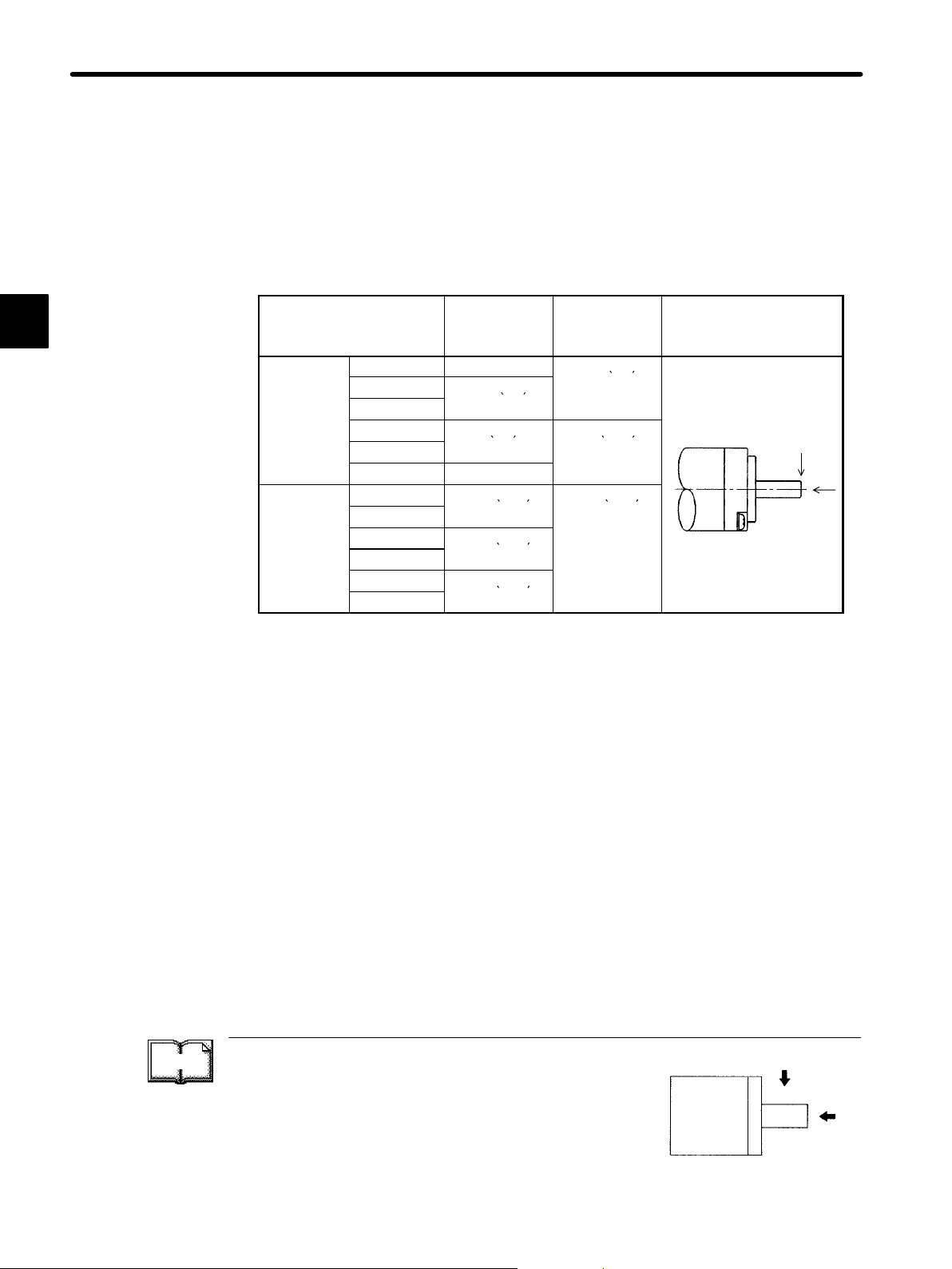
Allowable Load on Shaft End
1
Mechanical shock to the shaft end must be less than 490 m/s
2
and must be applied no
more than twice.
Design the mechanical system so that thrust load and radial load applied to the Servomotor shaft end during operation falls within the range shown in the following table.
Servomotor Model
SGMM-
Standard
With Gears
A1C31jj
A2C31jj
A3C31jj
B3CF1j
B5CF1j
B9CF1j
A1C3JAjj
A2C3JAjj
A1C3JBjj
A2C3JBjj
A1C3JCjj
A2C3JCjj
Allowable
Radial Load
Fr [N(lb)]
34.1 (7.7)
44.1 (9.9)
8 (1.8) 4.0 (0.90)
10 (2.2)
51.9 (11.7) 47.0 (10.5)
76.4 (17.2)
89.2 (20.1)
Allowable
Thrust Load
Fs [N(lb)]
14.7 (3.3)
Reference Drawing
Fr
Fs
TERMS
Note a) The box (j) at the end of the model number is for the shaft specifications.
b) The allowable load is applied to the shaft end.
Thrust load and radial load
Fr
Thrust load (Fs): Shaft-end load applied parallel to the
centerline of a shaft
Motor
Fs
Radial load (Fr): Shaft-end load applied perpendicular to
the centerline of a shaft
— 1-8 —
Shaft end
Page 22
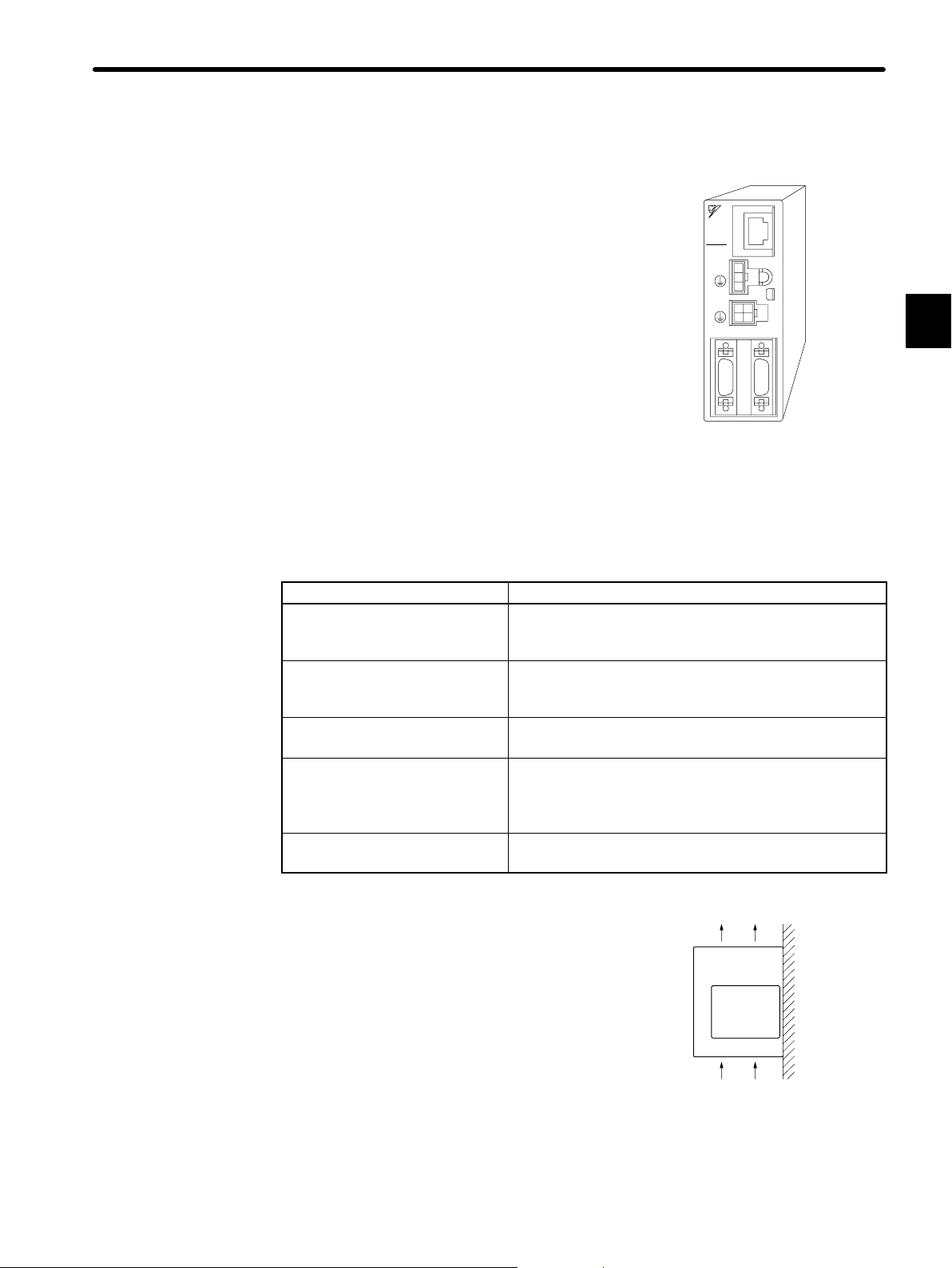
1.2.3 Installing the Servopack
The SGDF Servopack is a book-shaped compact servo controller.
Incorrect installation will cause malfunctions. Always
observe the following precautions when installing the
Servopack.
Storage:
When the Servopack is to be stored with the power cable disconnected, store it within the following
temperature range:
Between −20 °C and 85 °C
C
SERVOPACK
RDY
ALM
CN1/IO
N
5
SGDFA1CS
DC24V
CN3
CN4
CN2/PG
SGDF Servopack
1.2Installation
1
Installation Site
Situation Notes on Installation
Design the control panel size, Servopack layout, and
Installed in a control panel
cooling method so that the ambient temperature of the
Servopack does not exceed 50°C.
Suppress radiation heat from the heating unit and a rise
Installed near a heating unit
in temperature caused by convection so that the ambient
temperature of the Servopack does not exceed 50°C.
Installed near a source of
vibration
Install a vibration isolator underneath the Servopack to
prevent it from receiving vibration.
Corrosive gases do not immediately affect the Servopack
Installed in a place subject to
corrosive gases
but will eventually cause contactor-related devices to
malfunction. Take appropriate action to prevent corrosive
gases.
Others
Do not install in a hot and humid place or where
excessive dust or iron powder is present in the air.
Orientation:
Install the Servopack perpendicular to the wall as
shown in the figure.
The Servopack must be orientated as shown in
the figure because it is designed to be cooled by
natural convection.
• Firmly secure the Servopack to the mounting
surface through the mounting holes.
— 1-9 —
Ventilation
Page 23
BASIC OPERATION
1.2.3 Installing the Servopackcont.
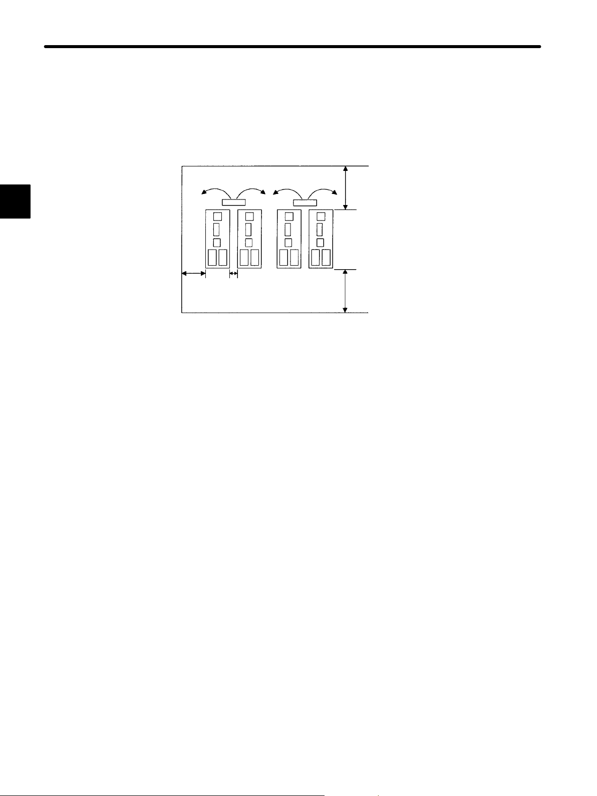
Installation Method
When installing multiple Servopacks side by side in a control panel, observe the following
installation method.
1
30 mm
or more
Fan 50 mm or more
10 mm
or more
Fan
50 mm or more
Servopack Orientation
Install Servopack perpendicular to the wall so that the front panel faces outward. The
front panel is the side to which the Digital Operator is connected.
Cooling
Provide sufficient space around each Servopack to allow cooling by natural convection
or fans as shown in the above diagram.
Adjacent Installation
When installing Servopacks side by side, provide at least 10 mm space between them
and at least 50 mm space above and below them as shown in the figure above. Install
cooling fans above the Servopacks to prevent the temperature around each Servopack
from increasing excessively and also to maintain the temperature inside the control panel
evenly.
Control Panel Environment Conditions
• Ambient temperature for Servopack: 0 °Cto50°C
• Humidity: 90% RH or less
• Vibration: 9.8 m/s
2
• Condensation and freezing: None
• Ambient temperature to ensure long-term reliability: 40 °C or less
— 1-10 —
Page 24

1.2.4 Power Loss
The amount of power lost by Servopacks at the rated output is shown in the following table.
1.2Installation
Servopack Type Capacity (W) Inrush Current
(Aop)
SGDF-A1C 10 3.8 2.1 7
SGDF-A2C 20 3.8 2.0 7
SGDF-A3C 30 3.8 2.9 7
SGDF-B3C 3 3.8 1.3 7
SGDF-B5C 5 3.8 1.3 7
SGDF-B9C 10 3.8 1.5 7
Output Current
(A rms)
Power Loss (W)
1
— 1-11 —
Page 25

1
BASIC OPERATION
1.3.1 Connecting to Peripheral Devices
1.3 Connection and Wiring
This section describes how to connect Σ-Series products to peripheral devices and
explains a typical example of wiring the main circuit. It also describes an example of
connecting to main host controllers.
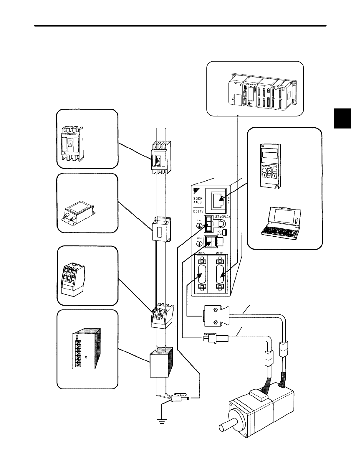
1.3.1 Connecting to Peripheral Devices
This section shows a standard example of connecting Σ-Series products to peripheral devices and briefly explains which peripheral devices can be connected and in which locations
to connect them.
— 1-12 —
Page 26
1.3Connection and Wiring
Molded-case circuit
breaker (MCCB)
Used to protect
power supply line.
Shuts the circuit
OFF when
overcurrent is
detected.
Noise filter
Used to eliminate external
noise from power supply line.
Molded-case
circuit breaker
Noise
filter
Power supply:
Single-phase
200 or 100 VAC
Host
Controller
MP910, MP920,
MP930, and MP−SG1 with a Motion Module
Connect the SGDP SERVOPACK to a
Yaskawa host controller.
Digital Operator
Personal computer
Connecting cable: JZSP-CFS01 to 03
Allows the user to
set parameters or
operation references
and display
operation status or
alarm status.
Personal computers
can also be used.
JUSP-OP02A-3
1
Magnetic contactor
Turns the Servo
ON or OFF.
Use a surge
suppressor for
the magnetic
contactor.
Model:
HI-Series
AC/DC power supply
Supplies Servopack
with 24 VDC.
Magnetic
contactor
AC/DC
power
supply
Power supply
ground line
Encoder cable
Motor cable
— 1-13 —
Page 27
BASIC OPERATION
1.3.2 Main Circuit Wiring and Power ON Sequence
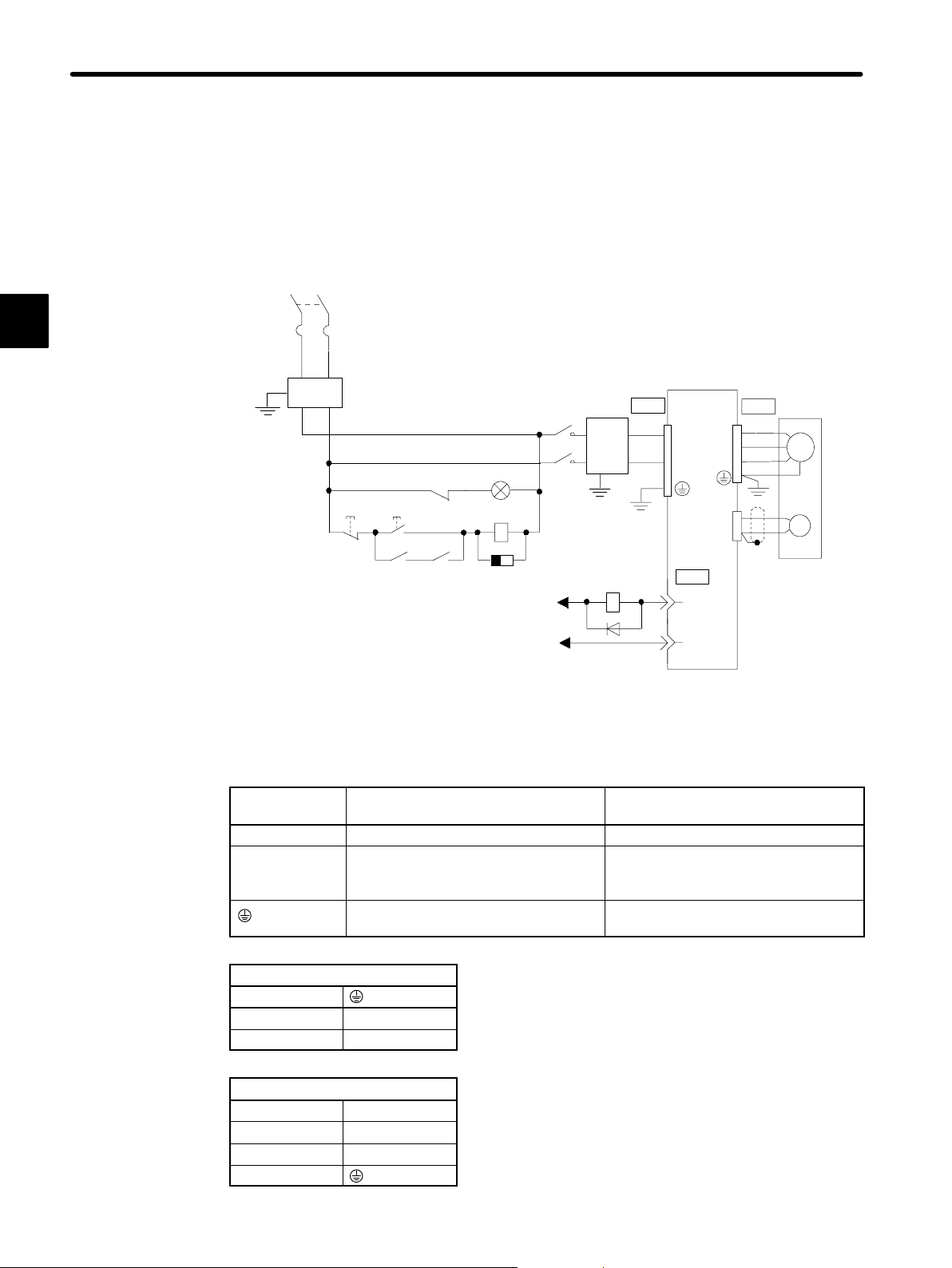
1.3.2 Main Circuit Wiring and Power ON Sequence
This section shows a typical example of wiring the main circuit for Σ-Series Servo, and describes the main circuit terminal functions and power ON sequence.
Typical Wiring Example
Single-phase 100 VAC
(50/60 Hz)
1
QF
FIL
ONOFF
MC Ry
QF: Circuit breaker
FIL: Noise filter
MC: Contactor
Ry: Relay
PL: Patrol light
SUP: Surge suppressor
D: Flywheel diode
Ry
MC
SUP
+24 V
024V
MC
Power
supply
Ry
Servopack
CN3 CN4
24 VDC
GND
CN1
7
ALM
3
SG-COM
Servomotor
M
PG
Overview and Functions of Main Circuit Terminals
The following tables show the name and description of each main circuit terminal function.
Terminal
Name Description
Symbol
CN3 Main input terminal
24 VDC ±10%
CN4 Motor connection terminal Connect U to the red motor terminal,
V to the white motor terminal, and W
to the blue motor terminal.
Ground terminal Connect to a ground and to the motor
(green).
CN3
1
2 GND
3 24 VDC
CN4
1 Phase U
2 Phase V
3 Phase W
4
— 1-14 —
Page 28
1.3Connection and Wiring
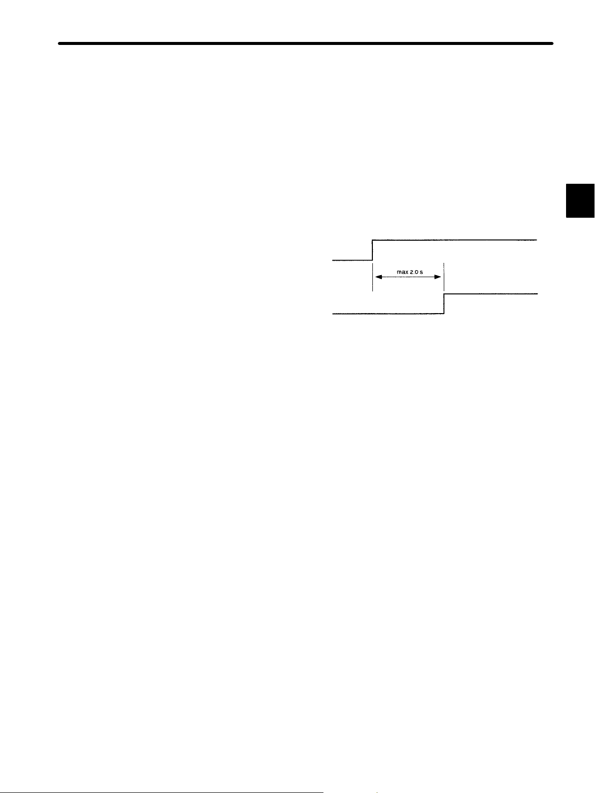
Designing the Power ON Sequence
Observe the following precautions when designing the power ON sequence.
• Design a power ON sequence so that the power is turned OFF when a servo alarm signal is
output. (See the previous circuit diagram.)
• Hold down the power ON push-button for at least two seconds. The Servopack outputs a
servo alarm signal for approximately two seconds or less when the power is turned ON. This
operation is required to initialize the Servopack.
Power supply
Servo alarm (ALM) output signal
1
Wiring Precautions
• After turning the power OFF, do not touch the power terminals for 5 minutes. Residual voltage may remain in the Servopack.
• Avoidfrequently turning the power ON and OFF.The Servopack has a capacitor in the power supply, so a high charging current flows when the power is turned ON. Therefore, frequently turning the power ON and OFF causes the main power devices (such as capacitors
and fuses) to deteriorate, resulting in unexpected problems.
— 1-15 —
Page 29
1
BASIC OPERATION
1.3.3 Examples of Connecting Host Controllers
1.3.3 Examples of Connecting Host Controllers
This section provides typical examples of connecting Servopacks to main host controllers.
Connection to other host controllers is also possible. Connect to the host controller according
to the connection examples shown below by referring to technical documentation for the host
controller.
Note This section describes signals related to the Servopack only. For other signals, refer to the
relevant technical documentation.
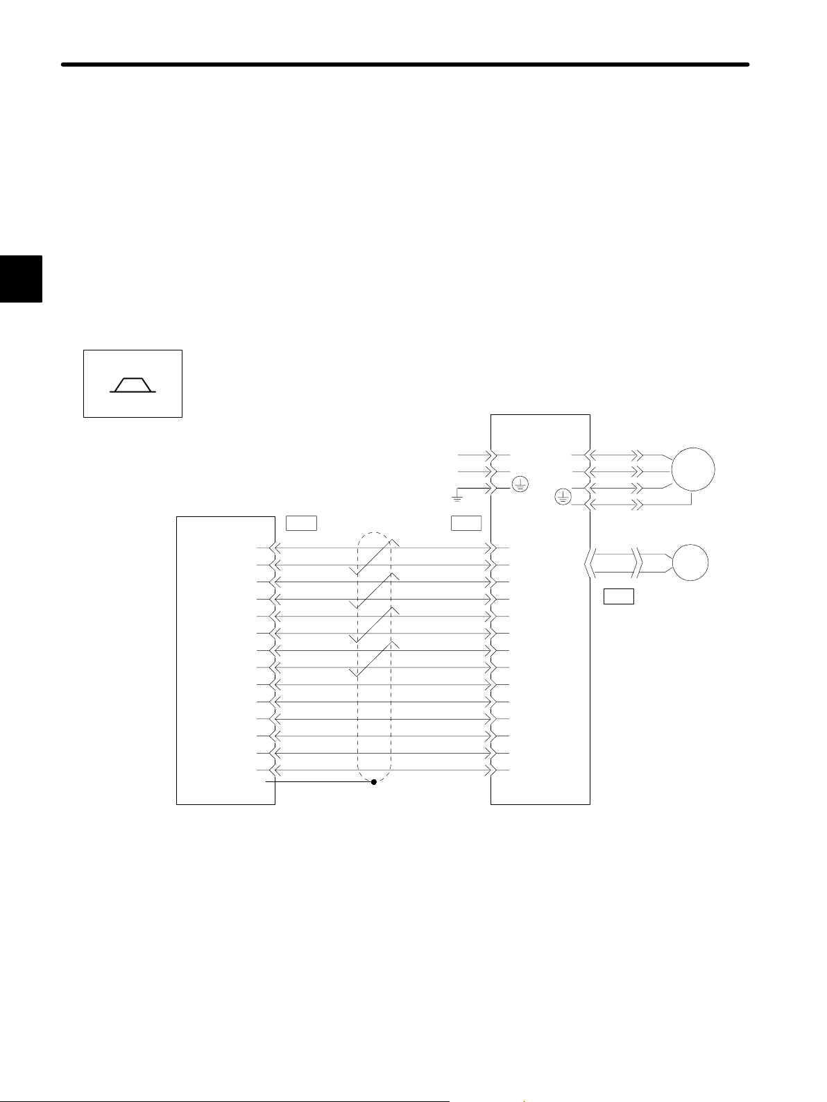
Example of Connecting to PROGIC-8
Servopack for Speed/Torque Control
Speed/Torque
Yaskawa
PROGIC-8
/PA
/PA
PB
/PB
PC
/PC
D/A
GND
+24OUT
SVON
PCON
(Reserved)
SVALM
OUT
O
24
(connector frame)
FG
1
2
3
4
5
6
7
8
19
11
12
16
15
17
Servopack
24VDC
GND
*1
CN1SV1
PAO
14
/PAO
15
PBO
16
/PBO
17
PCO
18
/PCO
19
12
V-REF (T-REF)
SG
13
+24VIN
9
*2
/S-ON
/P-CON
/ALMRST
7
ALM
3
SG-COM
U
V
W
CN2
*2
*2
M
PG
*1 These pin numbers are also applicable to SV2 to SV4.
*2 Set input signals IN1 and IN2 in the parameters.
— 1-16 —
Page 30
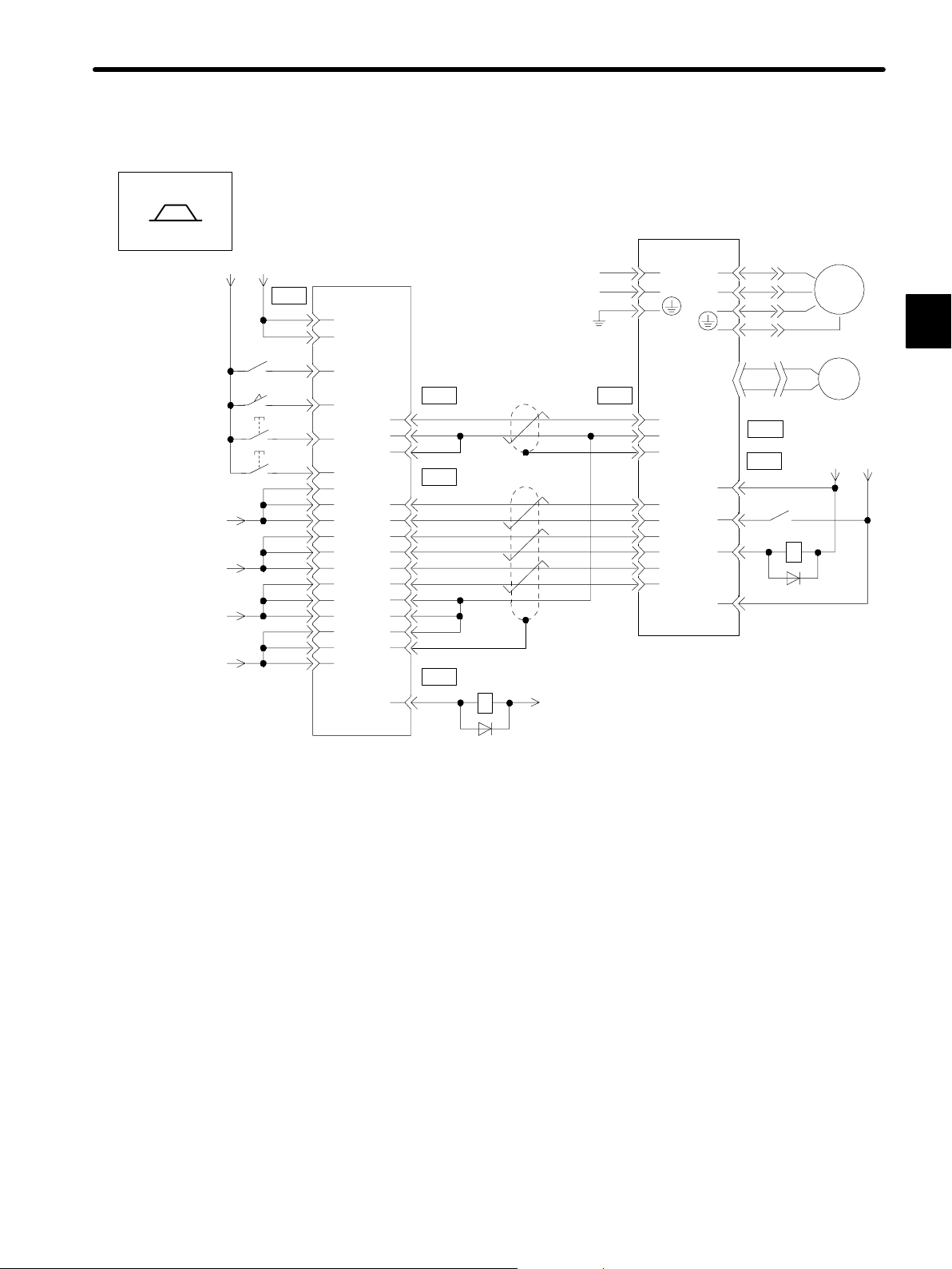
Example of Connecting to GL-series B2833 Positioning Module
Servopack for Speed/Torque Control
1.3Connection and Wiring
Speed/Torque
+12V
−12V
+5V
0V
ServomotorServopack
+24 V
V
0
24
CN2
1Ry
Yaskawa
JAMSC-B2833
1
33
SERVO NORMAL
20
DECEL LS
25
START
3
STOP
2
45
46
47
30
31
32
48
49
50
10
11
12
D/A OUTPUT
0V
0V
PA
/PA
PB
/PB
PC
/PC
0V
0V
0V
FG
ALARM
23
16
17
18
19
14
15
20
36
CN2
6
7
CN1
1
2
3
CN2
2Ry
+12V
DC24V
GND
CN1
12
V-REF (T-REF)
SG
13
20
FG
14
PAO
/PAO
15
PBO
16
17
/PBO
PCO
18
/PCO
19
*1 The ALM signal is output for approximately
two seconds when the power is turned ON.
Consider this when designing the power ON
sequence.
Use the ALM signal to operate the alarm
detection relay (relay 1Ry) and turn OFF the
power supply to the Servopack.
+24VIN
/S-ON
ALM
SG-COM
U
V
W
M
1
PG
CN2
CN1
9
1
7
3
+24 V 0
1Ry
*1
V
24
— 1-17 —
Page 31

BASIC OPERATION
1.3.3 Examples of Connecting Host Controllerscont.
Example of Connecting to GL-series B2813 Positioning Module
Servopack for Position Control
1
Positions
0
+12 V
+5 V
0V
ServomotorServopack
U
V
W
+24 VIN
/S-ON
ALM
SG-COM
CN2
CN1
9
1
7
3
M
PG
+24 V
*1
V
0
24
14
15
16
17
18
19
13
20
14
16
18
DC24V
GND
PULSE
/PULSE
SIGN
/SIGN
CLR
/CLR
SG
FG
PAO
PBO
PCO
V
+24 V
24
Yaskawa
JAMSC-B2833
1Ry
CN2
1
33
20
25
3
2
45
46
47
SERVO
NORMAL
DECEL LS
START
STOP
/PULSE
CN1 CN1
PULSE
24
23
SIGN
22
21
/SIGN
+12 V
CLR
0V
28
38
1kΩ
6
CN1
/PA
17
19
/PB
15
/PC
48
1
49
50
10
11
12
0V
0V
0V
FG
ALARM
36
2
3
20
CN2
2Ry
+12 V
*1 The ALM signal is output for approximately
two seconds when the power is turned ON.
Consider this when desigining the power ON
sequence.
Use the ALM signal to operate the alarm
detection relay (Relay 1Ry) and turn OFF the
power supply to the Servopack.
— 1-18 —
Page 32

1.3Connection and Wiring
Example of Connecting to OMRON C500-NC222 Position Control Unit
Servopack for Speed/Torque Control
Speed/Torque
(Made by OMRON)
C500-NC222
+24V
CCWLX
STPX
ORGX
EMGX
CWLX
DC GND
DC GND
+24V
OUT-1X
X-OUT
X-AG
I/O power supply
+
−
+24V
X-AXIS (Y-AXIS)
EXT IN
8
9
2 (12)
3 (13)
4 (14)
5 (15)
6 (16)
1
11
M/D
11
12
3 (19)
9 (25)
8 (24)
+24 V
V
0
24
(ON when positioning is stopped)
(ON when proximity is detected)
1Ry
*1
CN1
12
13
Servopack
DC24V
GND
ALM
7
SG-COM
3
+24VIN
9
/S-ON
1
V-REF (T-REF)
SG
Servomotor
U
V
W
CN2
M
PG
1
X-A
7 (23)
X-/A
X-/B
X-/C
*1 The ALM signal is output for approximately two seconds when the power is turned ON. Consider this when
designing the power ON sequence.
Use the ALM signal to operate the alarm detection relay (Relay 1Ry) and turn OFF the power supply to the
Servopack.
*2 : Twisted-pair cable
X-B
X-C
6 (22)
5 (21)
4 (20)
16 (14)
15 (13)
*2
14
15
17
16
18
19
20
PAO
/PAO
/PBO
PBO
PCO
/PCO
Note Only signals for the OMRON C500-NC221 Position Control Unit and the Yaskawa Servopack are
shown here.
— 1-19 —
Page 33

BASIC OPERATION
1.3.3 Examples of Connecting Host Controllerscont.
Example of Connecting to OMRON C500-NC112 Position Control Unit
Servopack for Position Control
1
Positions
I/O power supply
C500-NC112
(Made by OMRON)
+12V
CW LIMIT
CCW LIMIT
EMERGENCY
STOP
EXTERNAL
INTERRUPT
ORIGIN
ORIGIN
PROXIMITY
LOCAL
READY
+5V
+5V
PULSE OUTPUT
CW+CCW
DIRECTION
OUTPUT
CW
+24V
1A
1B
2A
2B
3A
3B
4A
4B
5A
5B
8A
8B
9A
9B
10A
10B
7A
7B
+
−
1Ry
+5V
+5V
+24V
0
24
1Ry
V
CN1
*1
10
13
14
15
16
17
18
19
7
3
Servopack
DC24V
GND
PCO
SG
ALM
SG-COM
PULS
/PULS
SIGN
/SIGN
CLR
/CLR
+24VIN
/S-ON
Servomotor
U
V
W
CN2
CN1
9
1
M
PG
External
power supply
+24V
*1 The ALM signal is output for approximately two seconds when the power is turned ON. Consider this when
designing the power ON sequence.
Use the ALM signal to operate the alarm detection relay (Relay 1Ry) and turn OFF the power supply to the
Servopack.
Note Only signals for the OMRON C500-NC112 Position Control Unit and the Yaskawa Servopack are
shown here.
— 1-20 —
Page 34

Example of Connecting to MITSUBISHI AD72 Positioning Unit
Servopack for Speed/Torque Control
1.3Connection and Wiring
Speed/Torque
AD72 (Made by
MITSUBISHI)
STOP
DOG
SV-ON
READY
SPEED
REFERENCE
PULSE A
PULSE B
PULSE C
0V
0V
0V
I/O power supply
+
−
+24V
*2
CONT
1
2
3
SERVO
1
2
3
4
5
6
ENCO
4
5
7
8
10
11
3
6
9
+24V
024V
(ON when positioning is stopped)
(ON when proximity is
detected)
1Ry
1Ry
*3
ServomotorServopack
DC24V
GND
CN1
+24VIN
9
/SV-ON
1
*1
ALM
7
SG-COM
3
V-REF (T-REF)
12
SG
13
PBO
16
/PBO
17
PAO
14
/PAO
15
18
PCO
/PCO
19
20
U
V
W
M
PG
1
*1 The ALM signal is output for approximately two seconds when the power is turned ON. Consider this when designing
the power ON sequence.
Use the ALM signal to operate the alarm detection relay (Relay 1Ry) and turn OFF the power supply to the Servopack.
*2 These pin numbers are the same for both X and Y axes.
*3 : Twisted-pair cable
Note Only signals for the MITSUBISHI AD72 Positioning Unit and the Yaskawa Servopack are shown here.
— 1-21 —
Page 35

BASIC OPERATION
1.3.3 Examples of Connecting Host Controllerscont.
Example of Connecting to MITSUBISHI AD75 Positioning Unit
Servopack for Position Control
1
Positions
I/O power supply
AD75 (Made by
MITSUBISHI)
READY
STOP
DOG
PGO
PULSE
SIGN
CLEAR
+
−
+24V
*2
X-AXIS (Y-AXIS)
1
7
14
11
24
25
3
21
4
22
5
23
+24V
024V
(ON when positioning is stopped)
(ON when proximity is
detected)
*1
1Ry
2.2kΩ
CN1
10
13
7
3
14
15
16
17
18
19
Servopack
DC24V
GND
PCO
SG
ALM
SG-COM
PULS
/PULS
SIGN
/SIGN
CLR
/CLR
+24VIN
/S-ON
Servomotor
U
V
W
CN2
CN1
9
1
M
PG
+24V
0
24
V
*1 The ALM signal is output for approximately two seconds when the power is turned ON. Consider this when
designing the power ON sequence.
Use the ALM signal to operate the alarm detection relay (Relay 1Ry) and turn OFF the power supply to the Servopack.
Note Only signals for the MITSUBISHI AD75 Positioning Unit and the Yaskawa Servopack are shown here.
— 1-22 —
Page 36

1.4 Conducting a Test Run
This section describes how to conduct a test run in two steps. The test run is divided into
two steps. Complete a test run in step 1 first, then proceed to step 2.
1.4Conducting a Test Run
1.4.1 Test Run in Two Steps
Conduct the test run when wiring is complete. By following the two steps (step 1 and 2) described below, the test run can be performed safely and correctly.
Note To prevent accidents, the test run in step 1 is conducted for a Servomotor under no load (i.e.,
Servomotor with all couplings and belts disconnected). Do not run the Servomotor while it is
connected to a machine.
Step 1: Conducting a test run for the motor without load Check that the motor is wired correctly....
Conduct a test run with the motor shaft disconnected
from the machine.
Purpose:
Outline:
• To check power supply circuit wiring
• To check motor wiring
• To check I/O signal (CN1) wiring
• Turn the power ON.
• Operate the motor with a digital op-
erator.
• Check I/O signals (CN1).
• Conduct a test run using I/O signals.
Check wiring.
Operate the motor with a Digital
Operator.
Do not connect to
a machine.
1
Step 2: Conducting a test run with the Servomotor and
machine connected Adjust the Servopack according to.................................
Servopack
Speed adjustment by
autotuning
Servomotor
Connect to the machine.
machine characteristics.
Connect the Servomotor to the machine and conduct
a test run.
Purpose:
Outline:
• To perform autotuning to adjust the motor according to machine characteristics
• To match the speed and direction of
rotation with the machine specifications
• To check the final control mode
• Perform autotuning.
• Adjust parameter settings.
• Record parameter settings.
When using a Servomotor with a brake, refer to 1.4.4 Supplementary Information on Test
Run before starting a test run.
— 1-23 —
Page 37

BASIC OPERATION
1.4.2 Step 1: Test Run for Servomotor without Load
1.4.2 Step 1: Test Run for Servomotor without Load
Check that the Servomotor is wired correctly. If the motor fails to rotate properly during a Servo Drive test run, the cause is usually incorrect wiring. Conduct a test run for the motor without
a load according to the procedure described below.
Secure the Servomotor.
1
Secure the Servomotor to the mounting surface to prevent it from moving during operation.
Always disconnect couplings and belts for step 1 of the test run.
Check the wiring.
Disconnect connector CN1, then check the Servomotor wiring in the power supply circuit. I/O
signals (CN1) are not used.
Turn ON the power.
Turn ON the Servopack power. If the Servopack is
turned ON normally, the 7-segment display on the Digital Operator will change as shown in the diagram.
Power will not be supplied to the Servomotor because
the servo is OFF.
Normal display
bb
Example of alarm display
c2
If an alarm display appears on the 7-segment display
as shown in the diagram above, the power supply circuit, Servomotor wiring, or encoder wiring is incorrect.
Turn OFF the power and correct the problem. Refer to
Appendix D List of Alarm Displays for details.
Operate using the Digital Operator.
Operate the Servomotor with the Digital Operator.
Check that the Servomotor runs normally.
Refer to 3.2.2 Operation Using the Digital Operator.
Connect signal lines.
Connect connector CN1 as follows:
(1) Turn OFF the power.
(2) Connect connector CN1.
(3) Turn ON the power again.
— 1-24 —
Operation by Digital Operator
If an alarm occurs, the power supply
circuit, motor wiring, or encoder
wiring is incorrect.
Page 38

1.4Conducting a Test Run
Check input signals.
Using the Digital Operator, check the input signal wir-
Example of
Un-05
Internal status bit display
(Un-05, Un-06)
/CL
ing in monitor mode. For the checking method, refer to
3.1.6 Operation in Monitor Mode.
Turn each connected signal line ON and OFF to check
/S-ON /P-CON
that the monitor bit display changes accordingly as
shown below.
Input Signal ON/OFF Monitor Bit Display
High level or open OFF Not lit
0 V level ON Lit
If the signal lines below are not wired correctly, the Servomotor fails to rotate. Always wire
them correctly. (If signal lines are not to be used, short them as necessary.) The signal lines
can be shorted externally by setting the memory switch.
Signal
Symbol
/S-ON CN1-1 Servo is turned ON when this input signal is at 0 V. However,
Connector
Pin No.
Description
leave the servo in OFF status.
1
Turn ON servo (motor).
Turn ON the servo as follows:
Check that no reference has been input.
/S-ON
0V
Servopack
CN1-1
Turn the servo ON.
• Speed/torque control: V-REF and T-REF are at 0 V.
• Position control: PULS and SIGN are fixed.
Set /S-ON to 0 V. If normal, the motor is turned
ON and the Digital Operator displays the data as
Display when Servo Is
Turned ON
shown in the figure. If an alarm display appears,
take appropriate action as described in Appendix
D List of Alarm Displays.
Operate by reference input.
The operating procedure differs according to the Servopack control mode used.
Servomotor
— 1-25 —
Page 39

BASIC OPERATION
1.4.2 Step 1: Test Run for Servomotor without Loadcont.
Servopack for Speed/Torque Control
1
Speed/Torque
This section describes the standard speed control
setting.
(1) Gradually increase the speed reference input
(V-REF, CN1-12) voltage. The Servomotor will
rotate.
Servomotor rotates at a speed
proportional to the reference voltage.
Servopack
CN1-12
CN1-13
Servomotor
When a host controller such as a Programmable Controller performs position control,
it may be difficult to directly input the speed reference voltage. In this case, constant
voltage reference should be input once to ensure correct operation.
(2) Check the following items in monitor mode. Refer to 3.1.6 Operation in Monitor Mode
for details.
Un-00
Actual motor speed
Un-01 Reference speed
• Has a reference speed been input?
• Is the motor speed as set?
• Does the reference speed match the actual Servomotor speed?
• Does the Servomotor stop when no reference is input?
(3) If the motor rotates at an extremely slow speed when 0 V is specified as the reference
voltage, correct the reference offset value as described in 3.2.4 Reference Offset Au-
tomatic Adjustment.
(4) To change the Servomotor speed or the direction of rotation, reset the parameters
shown below.
Cn-03
Speed reference gain
Refer to 2.2.1 Speed References.
Cn-02 bit 0 Reverse rotation mode
Refer to 2.1.1 Switching Motor Rotation Direction.
— 1-26 —
Page 40

Cn-02
Positions
1.4Conducting a Test Run
Servopack for Position Control
(1) Set parameter Cn-02 so that the reference pulse form matches the host controller out-
put form. Refer to 2.2.2 Position References for details on how to select reference
pulse forms.)
Selecting reference pulse form
Bit 3
Bit 4
Bit 5
Bit D
(2) Input slow speed pulses from the host control-
ler and execute low-speed operation.
(3) Check the following items in monitor mode:
Un-00
Actual motor speed
Un-07 Reference pulse speed display
Un-08 Position error
• Has a reference pulse been input?
• Is the motor speed as set?
Host
controller
Reference
pulse
/PULS
/SIGN
Servopack
CN1-14
CN1-15
CN1-16
CN1-17
1
Servomotor
• Does the reference speed match the actual Servomotor speed?
• Does the Servomotor stop when no reference is input?
(4) To change motor speed or the direction of rotation, reset the parameters shown be-
low.
Cn-24,Cn-25
Electronic gear ratio
Refer to 2.2.5 Electronic Gear.
Cn-02 bit 0 Reverse rotation mode
Refer to 2.1.1 Switching Motor Rotation Direction.
If an alarm occurs or the Servomotor fails to rotate during the above operation, connector
CN1 wiring is incorrect or the parameter settings do not match the host controller specifications. Check the wiring, review the parameter settings, and then repeat step 1.
— 1-27 —
Page 41

1
BASIC OPERATION
1.4.3 Step 2: Test Run with the Servomotor Connected to the Machine
1.4.3 Step 2: Test Run with the Servomotor Connected to the
Machine
Note Before proceeding to step 2, repeat step 1 (conducting a test run for the Servomotor without
load) until you are fully satisfied that the test has been completed successfully. Operation
faults that arise after the motor is connected to the machine not only damage the machine but
may also cause an accident resulting in injury or death. Test all items including parameter
settings and wiring as conclusively as possible before completing step 1.
After step 1 is complete, proceed to step 2, in which a test run is conducted with the Servomotor connected to the machine. The purpose of step 2 is to adjust the Servopack according to
the machine characteristics.
Conduct a test run according to the procedure described below.
(1) Check that power is OFF.
Turn OFF the Servopack power.
(2) Connect the Servomotor to the machine.
Refer to 1.2.2 Installing the Servomotor.
(3) Perform autotuning.
Tune the Servopack according to the machine
characteristics. Refer to 3.2.3 Autotuning.
(4) Operate by reference input.
As in step 1 (conducting a test run for Servomotor without load), perform Operate by refer-
ence input on page 1-25. Perform tuning with
the host controller.
(5) Set parameters and record the settings.
Set parameters as necessary. Record all the
parameter settings for maintenance purposes.
The test run is now completed.
Normally, the machine may generate much friction because of an insufficient running-in
period. After a test run is completed, perform adequate running-in.
— 1-28 —
Page 42

1.4.4 Supplementary Information on Test Run
In the following cases, always refer to the information described below before starting a test
run:
• When using a Servomotor with a brake
• When performing position control from the host controller
1.4Conducting a Test Run
Using a Servomotor with Brake
A Servomotor with a brake is used for vertical axes or axes subject to external force. The
brake prevents the motor shaft from rotating if it is subjected to an external force or the
force of gravity acting on the load when the Servomotor power is OFF.
Servopack uses the brake interlock output (/BK) signal to control holding brake operation
for a Servomotor with brake.
• Vertical axis
Servomotor
Holding brake
Prevents the
motor from
rotating due to
gravity
• Axis to which external force is applied
External force
Servomotor
Note Toprevent faulty operation caused by gravity (or external force), first check that the Servomo-
tor and holding brake operate normally with the Servomotor disconnected from the machine.
If all operations are normal, connect the Servomotor to the machine and conduct a test run.
1
For wiring of a Servomotor with a brake, refer to 2.4.3 Holding Brake.
Performing Position Control from the Host Controller
If the position control of the host controller is incomplete, check Servomotor operation
and then conduct a test run according to the following table. Always disconnect the Servomotor from the machine before conducting the test run or the Servomotor may run out
of control.
Servopack
Speed
reference
Host
controller
Position control
Speed control
M
Test run for
Servomotor
without load
— 1-29 —
Page 43

BASIC OPERATION
1.4.5 Minimum Parameters and Input Signals
1
Reference
from Host
Controller
Jogging
(constantspeed reference input from
host controller)
Simple positioning
Check
Items
Motor
speed
Number of
Servomotor
revolutions
Check Method Review Items
Check the Servomotor speed as follows:
D Use the speed monitor (Un-00) of
the Digital Operator.
D Run the Servomotor at low
speed. For example, input a
speed reference of 60 min
check that the Servomotor makes
one revolution per second.
D Input a reference equivalent to
one Servomotor revolution and
visually check that the
Servomotor shaft makes one
revolution.
1.4.5 Minimum Parameters and Input Signals
Minimum Parameters Required for Test Run
−1
Check whether the
speed reference gain
value (parameter
Cn-03) is correct.
and
Check whether the dividing ratio count (parameter Cn-0A) is correct.
For details on how to set each parameter, refer to 3.1.5 Operation in Parameter Setting Mode.
Servopack for Speed/Torque Control
Cn-03
Speed reference adjustment gain
Refer to 2.2.1 Speed References.
Cn-0A Encoder pulse dividing ratio
Refer to 2.2.3 Encoder Output.
Servopack for Position Control
Cn-02 bits 3,4,5
Reference pulse form selection
Refer to 2.2.2 Position References.
Cn-02 bit D Logic of reference pulse
Refer to 2.2.2 Position References.
Cn-02 bit F Reference pulse output form
Refer to 2.2.9 Reference Pulse Input Selection Func-
tion.
Cn-0A Encoder pulse dividing ratio
Refer to 2.2.3 Encoder Output.
Cn-24 Electronic gear ratio (numerator)
Refer to 2.2.5 Electronic Gear.
Cn-25 Electronic gear ratio (denominator)
Refer to 2.2.5 Electronic Gear.
After changing the Cn-02 setting, always turn OFF the power, then turn ON again.
Turning ON the power again validates the new settings.
— 1-30 —
Page 44

1.4Conducting a Test Run
Changing Servomotor Rotation Direction
If the specified direction of rotation differs from the actual direction of rotation, the wiring may be incorrect. In this case, recheck the wiring and correct it accordingly. If the
direction of rotation is to be reversed, recheck the wiring and set the following parameter:
Cn-02 (bit 0)
Reverse rotation mode
Refer to 2.1.1 Switching Motor Rotation Direction.
Minimum Input Signals Required for Test Run
The following table lists the minimum input signals required to conduct a test run.
Signal Name
/S-ON (servo ON) CN1-1
Pin
Number
Function
Switching between motor ON and OFF status. (The
memory switch can be used to eliminate the need for
external short-circuit wiring.)
1
— 1-31 —
Page 45

APPLICATIONS
This chapter is prepared for readers who have mastered the basic operating
procedures and wish to learn more about the applications. It explains how to
set parameters for each purpose and how to use each function. Read the applicable sections according to your requirements.
2.1 Setting Parameters According to Machine
Characteristics 2-4............................
2.1.1 Changing Motor Rotation Direction 2-4.....................
2.1.2 Torque Limit 2-5.......................................
2.2 Setting Parameters According to
Host Controller 2-9...........................
2.2.1 Speed References 2-9...................................
2.2.2 Position References 2-13..................................
2.2.3 Encoder Output 2-17.....................................
2.2.4 Contact I/O 2-21........................................
2.2.5 Electronic Gear 2-24.....................................
2.2.6 Contact Input Speed Control 2-28..........................
2.2.7 Torque Control 2-32.....................................
2.2.8 Reference Pulse Inhibit Function (INHIBIT) 2-36..............
2.2.9 Reference Pulse Input Filter Selection Function 2-37...........
2
2
2.3 Setting Up the Σ-Series Servopack 2-38............
2.3.1 Parameters 2-38.........................................
2.3.2 Jog Speed 2-39.........................................
2.4 Setting Stop Mode 2-40.........................
2.4.1 Offset Adjustment 2-40...................................
2.4.2 Zero-clamp 2-41........................................
2.4.3 Holding Brake 2-43......................................
— 2-1 —
Page 46

2
2.5 Running the Motor Smoothly 2-46................
2.5.1 Soft Start Function 2-46..................................
2.5.2 Smoothing 2-47.........................................
2.5.3 Gain Adjustment 2-47....................................
2.5.4 Offset Adjustment 2-48...................................
2.5.5 Torque Reference Filter Time Constant 2-48..................
2.6 Minimizing Positioning Time 2-49................
2.6.1 Autotuning 2-49........................................
2.6.2 Servo Gain 2-49........................................
2.6.3 Feed-forward Control 2-51................................
2.6.4 Proportional Control 2-51.................................
2.6.5 Setting Speed Bias 2-52..................................
2.6.6 Mode Switch 2-53.......................................
2.6.7 Speed Loop Compensation 2-58............................
2.7 Designing a Protective Sequence 2-60.............
2.7.1 Servo Alarm Output 2-60.................................
2.7.2 Servo ON Input Signal 2-62...............................
2.7.3 Positioning Complete Output 2-63..........................
2.7.4 Speed Coincidence Output 2-64............................
2.7.5 Running Output Signal 2-65...............................
2.8 Special Wiring 2-67............................
2.8.1 Wiring Precautions 2-67..................................
2.8.2 Wiring for Noise Control 2-69.............................
2.8.3 Using More Than One Servo Drive 2-73.....................
2.8.4 Connector Terminal Layouts 2-74..........................
— 2-2 —
Page 47

Before Reading this Chapter
This chapter describes how to use each CN1 connector I/O signal for the Servopack and how
to set the corresponding parameter.
Refer to the following chapters for further information on areas covered in this chapter.
• For a list of I/O signals, refer to Appendix B List of I/O Signals.
• For terminal arrangement for I/O signals, refer to 2.8.4 Connector Terminal Layout.
• For a list of parameters, refer to Appendix C List of Parameters.
• For information on setting parameters, refer to 3.1.5 Operation in Parameter Setting Mode.
Parameters are divided into the following two types.
Constants Usage
Memory switches
(Cn-01 and Cn-02)
Constant settings (Cn-03 and later) Set a numerical value such as a torque limit value or speed
Set each bit to ON or OFF to select a function.
loop gain.
2
— 2-3 —
Page 48

2
APPLICATIONS
2.1.1 Changing Motor Rotation Direction
2.1 Setting Parameters According to Machine Characteristics
This section describes how to set parameters according to the dimensions and
performance of the machine to be used.
2.1.1 Changing Motor Rotation Direction
The Servopack provides a reverse rotation mode in which the direction of Servomotor rotation can be reversed without altering the Servomotor wiring. With the standard setting,
forward rotation is defined as counterclockwise (ccw) rotation viewed from the drive end.
If reverse rotation mode is used, only the direction of motor rotation will be reversed. The
direction (+/−) of axial motion is reversed, but other items remain unchanged.
Reference Standard Setting Reverse Rotation Mode
Encoder output
Forward Run Reference
Reverse Run Reference
from Servopack
(Phase A)
PAO
PBO
(Phase B)
Encoder output
from Servopack
(Phase A)
PAO
PBO
(Phase B)
Setting Reverse Rotation Mode
Set bit 0 of memory switch Cn-02 to select reverse rotation mode.
Cn-02 Bit 0
Rotation Direction
Selection
Factory
Setting: 0
For Speed/Torque Control
and Position Control
Encoder output
from Servopack
(Phase A)
PAO
PBO
(Phase B)
Encoder output
from Servopack
(Phase A)
PAO
PBO
(Phase B)
Set the direction of rotation.
Setting Meaning
Forward rotation is defined as counterclockwise
0
rotation when viewed from the drive end.
Forward rotation is defined as clockwise rotation
1
when viewed from the drive end.
— 2-4 —
(Standard setting)
(Reverse rotation mode)
Page 49

2.1.2 Torque Limit
The Servopack can provide the following torque control.
• Level 1: To restrict the maximum output torque to protect the machine or workpiece (internal
torque limit)
• Level 2: To restrict torque after the motor moves the machine to a specified position (external torque limit)
• Level 3: To always control output torque, not speed
2.1Setting Parameters According to Machine Characteristics
This section describes how to use levels 1 and 2 of the torque restriction function.
How to Set Level 1: Internal Torque Limit
The maximum torque is restricted to the values set in the following parameters.
Cn-08
Cn-09
TLMTF
Forward Rotation
Torque Limit
TLMTR
Reverse Rotation
Torque Limit
Unit:%Setting
Range: 0 to
Maximum
Torque
Unit:%Setting
Range: 0 to
Maximum
Torque
Factory
Setting:
Maximum
Torque
Factory
Setting:
Maximum
Torque
For Speed/Torque
Control and Position
Control
For Speed/Torque
Control and Position
Control
Sets the maximum torque values for
forward rotation and reverse rotation,
respectively.
Sets these parameters when torque
must be restricted according to machine conditions.
This torque restriction function always
monitors torque, and outputs the signal
shown on the right when the limit value
Output Signal for Torque Restriction Function
D /CLT
D Status indication mode bit data
D Monitor mode (Un-05) bit 4
Parameter Setting: Cn-2C = 4
is reached.
Specifies a torque limit value in terms of
a percentage of the rated torque.
2
Example of Use: Machine Protection
Torque limit
Motor speed
Torque
— 2-5 —
Too small a torque limit value will result in torque shortage at acceleration or deceleration.
Page 50

2
APPLICATIONS
2.1.2 Torque Limitcont.
Using /CLT Signal
This section describes how to use contact output signal OUT2 as a torque limit output
signal.
I/O power supply
Photocoupler output
Maximum operating voltage
per output: 30 VDC
Maximum output current per
output: 50 mA DC
Servopack
CN1-8
CN1-3
/CLT
SG-COM
+24V
Torque Limit Output For Speed/Torque
Output → /CLT CN1-8
Control and
Position Control
This signal indicates whether motor output torque (current) is being restricted.
ON status: The circuit between CN1-8 and
CN1-3 is closed.
CN1-8 is at low level.
Motor output torque is being restricted.
(Internal torque reference is greater than the
preset value.) Output torque is restricted to
the torque limit value.
OFF status: The circuit between CN1-8 and
CN1-3 is open.
CN1-8 is at high level.
Motor output torque is not being restricted.
(Internal torque reference is equal to or below
the preset value.)
Preset Value: Cn-08 (TLMTF)
Cn-09 (TLMTR)
Cn-18 (CLMI) : At /CL input
Note This function is changed to another function depending on the setting of the pa-
rameter Cn-2C.
How to Set Level 2: External Torque Limit
First, use a contact input signal to make the torque
(current) limit value set in the parameter valid. Torque
limit cannot be set separately for forward and reverse
rotation.
To use this function, always set bit 2 of memory switch
Cn-02 to 0 (standard setting). The contact input speed
/CL
CN1-*1
Servopack
Without
torque limit
Speed
With
torque limit
Speed
control function cannot be used.
Torque
Torque
/CL
ON: CN1-*1 is at
low level.
OFF: CN1-*1 is at
high level.
Torque is restricted. Limit value:
Cn-18
Torque is not restricted. Normal operation status.
— 2-6 —
Page 51

The torque restriction function
outputs the signal shown on
the right.
Examples of Use:
D Forced stopping
D Holding workpiece by robot
2.1Setting Parameters According to Machine Characteristics
Output Signal for Torque Restriction Function
•
/CLT
• Status indication mode bit data
• Monitor mode Un-05 bit 4
Parameter Setting: Cn-2C = 4
Cn-18
CLMI
Forward/Reverse
External Torque Limit
Unit:%Setting
Range: 0 to
Maximum
Factory
Setting:
100
For Speed/Torque
Control and Position
Control
Torque
Sets a torque limit value when torque is to be restricted by external contact input.
This function is valid when bit 2 of memory switch Cn-02 is set to 0.
Using /CL Signal
This section describes how to use input signal /CL as torque limit input signals.
I/O power supply
+24V
+24VIN
Host controller
/CL
→ Input /CL CN1-*1
Servopack
CN1-9
CN1-*1
4.7kΩ
5mA
Photocoupler
Forward/reverse External
Torque Limit Input
For Speed/Torque
Control and
Position Control
2
These signals are for forward and reverse external torque (current) limit input.
This function is useful in forced stopping.
The signal shown on the right is output while
torque is being restricted.
— 2-7 —
Output Signal for Torque
Restriction Function
• /CLT
• Status indication mode bit data
• Monitor mode Un-05 bit 4
• Parameter Setting:
Cn-2C = 4
Page 52

APPLICATIONS
/CL
2.1.2 Torque Limitcont.
2
ON: CN1-*1 is at
low level.
OFF: CN1-*1 is at
high level.
Torque is restricted. Limit value:
Cn-18
Torque is not restricted. Normal operation status.
Note This function is changed to another function depending on the setting of parame-
ter Cn-2C.
To use input signal /CL as torque limit input signals, set the following parameters.
Cn-2A
Cn-2B
Input signal selection 1 (IN1)
CN1-1 input signal
Input signal selection 2 (IN2)
CN1-2 input signal
Factory
Setting: 0
Factory
Setting: 2
For Speed/Torque Control
and Position Control
For Speed/Torque Control
and Position Control
The function of the input signal changes according to the setting, as shown in the following diagram.
Servopack
/S-ON
/CL
IN1, IN2
Setting Meaning
0 /S-ON (Servo ON)
1 /P-CON (proportional control reference)
2 /ALMRST (alarm reset)
3 /CL (torque limit)
/P-CON
/P-CON
/ALMRST
/CL
— 2-8 —
Page 53

2.2Setting Parameters According to Host Controller
2.2 Setting Parameters According to Host Controller
This section describes how to connect a Σ-Series Servo to a host controller and how to
set parameters.
2.2.1 Speed References
Speed/Torque
Input a speed reference by using the following input signal “speed reference input.” Since this
signal can be used in different ways, set the optimum reference input for the system to be
created.
Servopack
Speed reference input
(analog voltage input)
Torque reference input
(analog voltage input)
V-REF (T-REF)
SG
: Twisted-pair cable.
→ Input V-REF CN1-12
→ Input SG CN1-13
Use these signals when speed control is selected (bits
A and B of memory switch Cn-01).
CN1-12
CN1-13
Speed reference
(Torque reference)
Speed Reference Input For Speed/Torque
Control
Signal Ground for Speed
Reference Input
Reference
speed
For Speed/Torque
Control
(min−1)
2
For ordinary speed control, always wire the V-REF
and SG terminals.
Motor speed is controlled in proportion to the input
Standard
setting
−1500
−3000
−4500
Input voltage (V)
Set the slope in
Cn-03 (VREFGN).
voltage between V-REF and SG.
Setting Example
Cn-03 = 500: This setting means that 6 V is equivalent to rated speed (3000 min
Examples:
+6 V input → 3000 min
+1 V input → 500 min
−3 V input → 1500 min
−1
in forward direction
−1
in forward direction
−1
in reverse direction
— 2-9 —
−1
)
Page 54

APPLICATIONS
2.2.1 Speed Referencescont.
Parameter Cn-03 can be used to change the voltage input range.
2
V-REF
SG
Servopack
CN1-12
CN1-13
Example of Input Circuit
The adjacent diagram shows an example of an input
circuit.
For noise control, always use twisted-pair cable.
+12V
470 Ω, 1/2 W or more
2kΩ
: Twisted-pair cable.
Recommended Variable Resistor for Speed Setting:
Type 25HP-10B manufactured by Sakae Tsushin Kogyo Co., Ltd.
V-REF
SG
PAO
/PAO
PBO
/PBO
Servopack
CN1-12
CN1-13
CN1-14
CN1-15
CN1-16
CN1-17
When position control is performed by a host controller such as a Programmable Controller, connect VREF and SG to speed reference output terminals on
the host controller. In this case, adjust Cn-03 according to output voltage specifications.
Host controller
Speed
reference
output
terminals
Feedback
pulse input
terminals
: Twisted-pair cable.
Use the memory switch and input signal /P-CON to specify one of the four modes shown below.
Speed/Torque
Cn-01 Bit A
Control Mode Selection Factory
For Speed/Torque Control
Setting: 0
Cn-01 Bit B
Control Mode Selection Factory
For Speed/Torque Control
Setting: 0
The Servopack for speed/torque control provides three different control modes.
— 2-10 —
Page 55

Cn-01
Control
Mode
0
1
Setting
Bit B Bit A
2.2Setting Parameters According to Host Controller
Control Mode
Speed Control
This is normal speed control.
D Speed reference is input from V-REF.
D /P-CON signal is used to switch between P
control and PI control.
Speed
reference
P/PI
changeover
Servopack
(CN1-12)
/P-CON
(CN1-*1)
0 0
CN1-*1 is
PI control
open
CN1-*1 is at0VP control
D Torque reference input T-REF cannot be
used.
Zero-clamp Speed Control
This speed control allows the zero-clamp
function to be set when the motor stops.
D Speed reference is input from V-REF.
D /P-CON signal is used to turn the
zero-clamp function ON or OFF.
CN1-*1 is
open
Turns zero-clamp
function OFF
Servopack
Speed
reference
(CN1-12)
Zero-clamp
Zero-clamp is performed when
the following two conditions are
met:
Condition 1: /P-CON is turned
ON.
Condition 2: Motor speed drops
below the preset value.
Preset value: Cn-0F (ZCLVL)
/P-CON
(CN1-*1)
2
CN1-*1 is at0VTurns zero-clamp
function ON
D Torque reference input T-REF cannot be
used.
1 0 Torque control
For details on torque control, refer to 2.2.7 Torque Control.
— 2-11 —
Page 56

2
APPLICATIONS
2.2.1 Speed Referencescont.
Using /P-CON Signal:
Proportional Control, etc. For Speed/Torque
→ Input /P-CON CN1-*1
Control and
Position Control
The function of input signal /P-CON changes with the memory switch setting.
Servopack
Switching between P control and PI control
/P-CON
Switching between zero-clamp enabled mode and
zero-clamp disabled mode
Memory
switch
Memory Switch
Cn-02
Bit 2
Cn-01
Bit B
0 0 0
0 0 1
0 1 0 Not used (for speed/torque control only)
0 1 1 Not used (do not set)
1 --- ---
Changing rotation direction
Cn-01
Bit A
Switching between proportional (P) control and
proportional/integral (PI) control
Switching between zero-clamp enabled/disabled mode
(for speed/torque control only)
Changing the direction of rotation during contact input speed
control
Meaning of /P-CON Signal
Speed/Torque
TERMS
Adjust the speed reference gain using the following parameter.
Cn-03
VREFGN Speed
Reference Gain
Unit:
(min
−1
)/V
Setting
Range: 0
to 2162
Factory
Setting:
500
For Speed/Torque
Control
This parameter is for speed/torque control only.
Sets the voltage range for speed reference input
V-REF. Sets this parameter according to the out-
Reference
speed (min−1)
Set this slope.
put form of the host controller or external circuit.
Reference
voltage (V)
The factory setting is as follows:
Rated speed (3000 min
−1
)/6 V = 500
Zero-clamp function
This function is used for a system in which the host controller does not form a position loop.
In this case, the stopping position may shift even if a speed reference is set to 0. If the zeroclamp function is turned ON, a position loop is internally formed so that the stopping position
is firmly “clamped.”
— 2-12 —
Page 57

2.2.2 Position References
Input a position reference by using the following input signal “reference pulse input.” Since
there are several specifications for input signal, select reference input for the system to be
created.
Positions
Pulse Input Reference
2.2Setting Parameters According to Host Controller
Inputs a move reference by pulse input.
Position reference can correspond to the
following three types of output form:
• Line driver output
• +12V Open collector output
• +5V Open collector output
Connection Example 1: Line Driver Output
Line Driver Used:
SN75174 manufactured by
Texas Instruments Inc., or
MC3487 or equivalent.
Reference
pulse input
Reference
sign input
Error counter
clear input
Host controller
Line driver
PULS
/PULS
SIGN
/SIGN
CLR
/CLR
: Twisted-pair cable.
PULS
/PULS
SIGN
/SIGN
CLR
/CLR
CN1-14
CN1-15
CN1-16
CN1-17
CN1-18
CN1-19
CN1-14
CN1-15
CN1-16
CN1-17
CN1-18
CN1-19
Servopack
2
Servopack
Photocoupler
150Ω
Connection Example 2: Open Collector Output
Sets the value of limiting resistor R1 so that input cur-
Host controller
Vcc
rent i falls within the following range:
Input Current i: 7 to 15 mA
Examples:
Tr1
R1
• When Vcc is 12 V,
R1 = 1 kΩ
• When Vcc is 5 V,
R1
R1 = 180 Ω
— 2-13 —
: Twisted-pair cable.
R1
i
/PULS
/SIGN
: Twisted-pair cable.
PULS
SIGN
CLR
/CLR
CN1-14
CN1-15
CN1-16
CN1-17
CN1-18
CN1-19
Servopack
Photocoupler
150Ω
Page 58

APPLICATIONS
Pul
MotorF
d
R
MotorR
p
0
pulse
og c
90
2.2.2 Position Referencescont.
Note The signal logic for open collector output is as follows.
When Tr1 is ON Equivalent to high level input
When Tr1 is OFF Equivalent to low level input
Selecting Reference Pulse Form
Use the following memory switches to select the reference pulse form to be used:
2
Positions
→ Input PULS CN1-14
→ Input/PULS CN1-15
→ Input SIGN CN1-16
→ Input/SIGN CN1-17
Reference Pulse Input For Position Control
Reference Pulse Input For Position Control
Reference Sign Input For Position Control
Reference Sign Input For Position Control
The motor rotates at an angle proportional to the input pulse.
Cn-02 Bit 3
Cn-02 Bit 4
Cn-02 Bit 5
Reference Pulse Form
Selection
Reference Pulse Form
Selection
Reference Pulse Form
Selection
Factory
Setting: 0
Factory
Setting: 0
Factory
Setting: 0
Sets the form of a reference pulse that is externally
output to the Servopack.
Sets the pulse form according to the host controller
specifications.
Set also the input pulse logic in bit D of Cn-02.
Bit D
Cn-02
Bit5Bit4Bit
3
Input
Multipli-
er
se
Refer-
ence
Pulse
Form
orwar
Reference
Sign +
pulse
0 0 0
train
For Position Control
For Position Control
For Position Control
Host
controller
Position
reference
pulse
un
Reference
Servopack
CN1-14
CN1-16
everseRun
Two-
0
(Posi-
tive
logic
setting)
0 1 0
0 1 1
1 0 0
¢1
¢2
¢4
phase
ulse
train
with
90°
phase
difference
CW
pulse +
0 0 1
CCW
pulse
— 2-14 —
Page 59

2.2Setting Parameters According to Host Controller
p
1
pulse
og c
90
Refer-
Refer-
ence
ence
Pulse
Pulse
Form
Form
Bit D
Cn-02
Bit
5
Bit
4
Bit
3
Input
Input
Pulse
Pulse
Multipli-
Multipli-
er
er
Sign +
pulse
0 0 0
train
Two-
1
(Nega-
tive
logic
setting)
0 1 0
0 1 1
1 0 0
¢1
¢2
¢4
phase
ulse
train
with
90°
phase
difference
CW
pulse +
0 0 1
CCW
pulse
Input Pulse Multiply Function:
When the reference form is two-phase pulse train
with 90° phase difference, the input pulse multiply
function can be used.
Motor Forward Run
Motor Forward Run
Reference
Reference
Number of
motor move
pulses
Motor Reverse Run
Motor Reverse Run
Reference
Reference
Input reference pulse
2
x4
x2
x1
The electronic gear function can also be used to
convert input pulses.
Example of I/O Signal Generation Timing
Servo ON
Base block
Sign +
pulse train
PG pulse
SIGN
PULS
/COIN
Release
t1 ≤ 30 ms
t2 ≤ 6ms
(When parameter
Cn-12 is set to 0)
t3 ≥ 40 ms
t4, t5, t6 ≤ 2ms
t7 ≥ 20 μs
Note (1) The interval from the time the Servo ON signal is turned ON until a reference pulse is
input must be at least 40 ms. Otherwise, the reference pulse may not be input.
— 2-15 —
Page 60

2
APPLICATIONS
2.2.2 Position Referencescont.
(2) The error counter clear (CLR) signal must be ON for at least 20 μs. Otherwise, it be-
comes invalid.
Allowable Voltage Level and Timing for Reference Pulse Input
Reference Pulse Form Electrical Specifications Remarks
Sign + pulse train input
(SIGN + PULS signal)
Maximum reference
frequency: 450 kpps
¨ reference © reference
The signs for each
reference pulse are as
follows:
¨: High level
©: Low level
90° different two-phase
pulse train
(phase A + phase B)
Maximum reference
Phase A
Phase B
Parameter Cn-02 (bits 3,
4 and 5) is used to
switch the input pulse
multiplier mode.
frequency
x 1 multiplier:
450 kpps
x 2 multiplier:
Phase B is 90°
forward from phase B
Phase B is 90°
behind phase B
400 kpps
x 4 multiplier:
200 kpps
CCW pulse + CW pulse
Maximum reference
frequency: 450 kpps
SIGN
PULS
¨ reference © reference
CCW pulse
CW pulse
Clearing the Error Counter
Use the following procedure to clear the contents of the error counter.
Positions
→ Input CLR CN1-18
→ Input/CLR CN1-19
Error Counter Clear Input For Position
Error Counter Clear Input For Position
Setting the CLR signal to high level will set the following conditions:
• Sets the error counter inside the Servopack to 0.
• Disables position loop control.
— 2-16 —
Control
Control
Servopack
Clear
Position loop
error counter
Page 61

2.2Setting Parameters According to Host Controller
Use this signal to clear the error counter from the host controller.
Bit A of memory switch Cn-02 can be set so that the error counter is cleared only once when
the leading edge of an input pulse rises.
Cn-02 Bit A
Selects the pulse form of error counter clear signal CLR.
Setting Meaning
Clears the error counter when the CLR
signal is set at high level. Error pulses
0
do not accumulate while the signal
remains at high level.
Clears the error counter only once when
the rising edge of the CLR signal rises.
1
2.2.3 Encoder Output
Encoder output signals divided inside the Servopack can be output externally. These signals
can be used to form a position control loop in the host controller.
Error Counter Clear Signal
Selection
Factory
Setting: 0
For Position Control
2
Cleared state
Cleared only once at this point
TERMS
This output is
explained here.
Host
controller
Servomotor
encoder
Phase A
Phase B
Phase C
Servopack
CN2 CN1
Frequency
dividing
circuit
Divided (or dividing)
“Dividing” means converting an input pulse train from the encoder mounted on the motor
according to the preset pulse density and outputting the converted pulse. The unit is pulses
per revolution.
— 2-17 —
Page 62

APPLICATIONS
2.2.3 Encoder Outputcont.
Speed/Torque Control
The output circuit is for line driver output. Connect each signal line according to the following
circuit diagram.
2
Servopack
OV
CN1-14
CN1-15
CN1-16
CN1-17
CN1-18
CN1-19
CN1-13
CN1-20
PAO
/PAO
PBO
/PBO
PCO
/PCO
Phase A
Phase B
Phase C
: Twisted-pair cable
I/O signals are described below.
Host controller
Line receiver
R
R
R
2
1
6
7
10
9
8COV16
3
5
11
Choke
coil
+5V
Smoothing
capacitor
+
−
Phase
A
Phase
B
Phase
C
+5V
0V
Line receiver used: SN75175 manufactured by Texas
Instruments Inc. or MC3486 (or
equivalent)
R (termination resistor): 220 to 470 Ω
C (decoupling capacitor): 0.1 µF
Output → PAO CN1-14
Output →/PAO CN1-15
Output → PBO CN1-16
Output →/PBO CN1-17
Output → PCO CN1-18
Output → /PCO CN1-19
Encoder Output
Phase A
Encoder Output
Phase A
Encoder Output
Phase B
Encoder Output
Phase B
Encoder Output
Phase C
Encoder Output
Phase C
For Speed/Torque Control
For Speed/Torque Control
For Speed/Torque Control
For Speed/Torque Control
For Speed/Torque Control
For Speed/Torque Control
— 2-18 —
Page 63

2.2Setting Parameters According to Host Controller
Position Control
The output circuit is for open-collector outputs. Connect each signal line according to the following circuit diagram.
Servopack Host controller
VCC
CN1-11
Phase A
CN1-12
Phase B
CN1-10
Phase C
CN1-13
0V
CN1-20
I/O signals are described below.
Output → PAO CN1-11
Output → PBO CN1-12
Output → PCO CN1-10
PAO
PBO
PCO
SG
Encoder Output
Phase A
Encoder Output
Phase B
Encoder Output
Phase C
2
0V
For Position Control
For Position Control
For Position Control
Divided encoder signals are output.
Always connect these signal terminals when a position loop is formed in the host controller to
perform position control.
Set a dividing ratio in the following parameter.
Dividing ratio setting
Cn-0A PGRAT
The dividing ratio setting is not relevant to the gear ratio setting (Cn-24, 25) for the electronic
gear function of the Servopack for position control.
— 2-19 —
Page 64

APPLICATIONS
2.2.3 Encoder Outputcont.
Output Phase Form
Forward rotation Reverse rotation
Phase A
Phase B
Phase A
Phase B
2
Phase C
Output → SG CN1-13
Output → FG CN1-20
Signal Ground for
Encoder Output
Frame Ground For Speed/Torque Control
SG: Connect to 0 V on the host controller.
FG: Connect to the cable shield wire.
Setting the Pulse Dividing Ratio
Set the pulse dividing ratio in the following parameter.
PGRAT
Dividing Ratio Setting
Cn-0A
Unit:
P/R
Setting
Range: 16
to No. of
Encoder
Pulses
* : 1024 for SGDF-BjCj
Phase C
For Speed/Torque Control
and Position Control
and Position Control
Factory
Setting*:
2048
For Speed/Torque
Control and Position
Control
Sets the number of output pulses for PG output sig-
nals (PAO,
PAO, PBO and/PBO).
/
Pulses from motor encoder (PG) are divided by the
Servomotor
encoder
Servopack
Frequency
dividing
Output terminals:
PAO
PAO
/
PBO
PBO
/
Phase A
Phase B
preset number of pulses before being output.
The number of output pulses per revolution is set in this parameter.Set this value according to
the reference unit of the machine or controller to be used.
The setting range varies according to the encoder used.
Setting example:
Servopack Type Encoder Number of Encoder Pulses Per Revolution Setting Range
SGDF-AjCj
SGDF-BjCj
Incremental
encoder
2048 pulses per revolution 16 to 2048
1024 pulses per revolution 16 to 1024
Preset value: 16
1 revolution
— 2-20 —
Page 65

2.2.4 Contact I/O
S
k
Contact I/O are sequence I/O signals used to control Servopack operation. Connect these
signal terminals as necessary.
Connecting Contact Input Signals
Connect contact input signal terminal connections as follows:
I/O power
supply
Host controller
+24V
+24VIN
IN1
CN1-9
CN1-1
ervopac
Photocoupler
4.7 KΩ
5mA
2.2Setting Parameters According to Host Controller
2
IN2
0V
CN1-2
Note Provide an external I/O power supply separately.
There are no power terminals to which the Servopack outputs signals externally.
External Power Supply: 24 1 VDC
50 mA or more
Yaskawa recommends that this external power supply be the same type as for the output circuit.
Input
→ Input IN1 CN1-1
→ Input IN2 CN1-2
Signal
Selection 1
Input
Signal
Selection 2
The function of input signal IN1 differs according to the setting of parameter Cn-2A.
The function of input signal IN2 differs according to the setting of parameter Cn-2B.
Factory Setting: 0 For Speed/Torque
Control and
Position Control
Factory Setting: 2 For Speed/Torque
Control and
Position Control
Servopack
/S-ON
/CL
IN1,IN2
/P-CON
/ALMRST
/CL
— 2-21 —
Page 66

APPLICATIONS
2.2.4 Contact I/Ocont.
Setting Meaning
0 /S-ON (Servo ON)
1 /P-CON (proportional control reference)
2 /ALMRST (alarm reset)
3 /CL (torque limit)
External I/O Power Supply For Speed/Torque
→ Input +24VIN CN1-9
Control and
Position Control
2
This external power supply input terminal is common to the following contact input signals:
I/O power
supply
Contact Input Signals: /S-ON
/P-CON
Connect an external I/O power supply.
/ALMRST
/CL
Contact Output Signal Terminal Connections
Connect contact output signal terminal connections as follows:
These output signals are used
to indicate Servopack operation
status.
Photocoupler output
Per output
Maximum: operational
voltage: 30 VDC
Maximum output current:
50 mA DC
Servopack
Photocoupler
CN1-7
MAX 50mA
CN1-3
CN1-8
MAX 50mA
ALM
SG-COM
OUT2
Note Provide an external I/O power supply separately.
There are no power terminals to which the Servopack outputs signals externally.
Yaskawa recommends that this external power supply be the same type as for the
input circuit.
Servopack
CN1-19
I/O power
supply
+24V
Output → OUT2 CN1-7
— 2-22 —
Output
Signal
Selection 2
Factory Setting: 3 For Speed/Torque
Control and
Position Control
Page 67

2.2Setting Parameters According to Host Controller
The function of output signal OUT2 differs according to the setting of parameter Cn-2C.
Servopack
Setting Meaning
0 ALM (alarm output)
1 /TGON (rotation detection)
2 /BK (brake interlock output)
3 /V-CMP (speed coincidence output for speed/torque
control)
/COIN (positioning completed signal for positioning
control)
4 /CLT (torque limit detection output)
2
Output → SG-COM CN1-3
Output Signal Ground
Common
For Speed/Torque
Control and
Position Control
This signal ground is used for the following output signals. Connect to 0 V on the external
power supply.
Contact Output Signals: ALM
/TGON
/BK
/V-CMP (for speed/torque control only)
/COIN (for position control only)
/CLT
— 2-23 —
Page 68

APPLICATIONS
2.2.5 Electronic Gear
2.2.5 Electronic Gear
Positions
The electronic gear function enables the motor travel distance per input reference pulse to be
set to any value. It allows the host controller to perform control without having to consider the
machine gear ratio and the number of encoder pulses.
2
When Electronic Gear Function
is Not Used
Workpiece
Number of
encoder
pulses: 2048
To move a workpiece 10 mm,
One revolution is equivalent to 6 mm, so
10 6 = 1.6666 (revolutions)
2048 x 4 (pulses) is equivalent to one revolution, so
1.6666 x 2048 x 4 = 13653 (pulses)
A total of 13653 pulses must be input as a reference.
the host controller needs to make this calculation.
Ball screw
pitch: 6 mm
When Electronic Gear Function is Used
Workpiece
Number of
encoder
pulses: 2048
Machine conditions and reference unit
must be defined for the electronic gear
function beforehand.
To move a workpiece 10 mm:
Reference unit is 1 μm, so
10 mm 1 μm = 10,000 pulses
Reference
unit: 1 μm
Ball screw
pitch: 6 mm
Setting the Electronic Gear
Calculate the electronic gear ratio (B/A) according to the procedure below and set the value in
Cn-24 and Cn-25.
1) Check the machine specifications.
Items related to electronic gear:
− Gear ratio
− Ball screw pitch
− Pulley diameter
2) Check the number of encoder pulses for the Servomotor.
Motor Model Encoder Type Number of Encoder
Pulses Per Revolution
SGMM-AjC31j
SGMM-BjCF1j
Incremental encoder
Same as parameter Cn-11 settings.
— 2-24 —
Ball screw pitch
Gear ratio
2048
1024
Page 69

3) Determine the reference unit to be used.
2.2Setting Parameters According to Host Controller
Reference unit is the minimum unit of position
data used for moving the load.
To move a table in 0.001 mm units
Reference unit: 0.001 mm
(Minimum unit of reference from host controller)
Examples:
0.01 mm, 0.001 mm, 0.1°, 0.01 inch
Reference input of one pulse moves the load by
one reference unit.
Determine the reference unit according to
machine specifications and positioning
accuracy.
Example: When reference unit is 1 μm
If a reference of 50,000 pulses is input, the load moves 50 mm (50,000 x 1 μm).
4) Determine the load travel distance per revolution of load shaft in reference units.
Load travel distance per revolution of load shaft (in reference units)
Load travel distance per revolution of load shaft (in unit of distance)
=
Reference unit
Example: When ball screw pitch is 5 mm and reference unit is 0.001 mm
5/0.001 = 5000 (reference units)
Ball Screw Disc Table Belt & Pulley
2
Load shaft
Load shaft
360°
1 revolution
=
P: Pitch
P
Reference unit
1 revolution
5) Determine the electronic gear ratio
=
Reference unit
B
.
A
If the load shaft makes “n” revolutions when the motor shaft makes “m” revolutions, the
n
gear ratio of motor shaft and load shaft is
B
Electronic gear ratio
Travel distance per revolution of load shaft (in reference units)
=
A
Number of encoder pulses x 4
.
m
Note Check that the electronic gear ratio meets the following condition:
B
0.01≦Electronic gear ratio
100
≦
A
Load shaft
1 revolution
×
D: Pulley diameter
π D
=
Reference unit
m
n
If the electronic gear ratio is outside this range, the Servopack will not work properly. In
this case, modify the load configuration or reference unit.
— 2-25 —
Page 70

APPLICATIONS
2.2.5 Electronic Gearcont.
6) Set the electronic gear ratio in the parameters below.
B
Reduce the electronic gear ratio
integer smaller than 65535, then set A and B in the following parameters.
to their lowest terms so that both A and B are an
A
2
B
A
Cn-24
Cn-25
These parameters are for position control only.
Set the electronic gear ratio according to machine
specifications.
Electronic gear ratio
B = [(Number of encoder pulses) x 4] x [Motor shaft rotating speed]
A = [Reference unit (load travel distance per revolution of load shaft)] x [Load shaft ro-
tating speed]
Cn-24 RATB Electronic gear ratio (numerator)
Cn-25 RATA Electronic gear ratio (denominator)
RATB
Electronic Gear Ratio
Numerator
RATA
Electronic Gear Ratio
Denominator
B
=
A
Cn-24
Cn-25
Unit:
None
Unit:
None
Setting
Range: 1
to 65535
Setting
Range: 1
to 65535
Factory
Setting: 4
Factory
Setting: 1
Input
reference
pulse
For Position Control
For Position Control
Servopack
Electronic
gear
Servomotor
The parameter settings must meet the following condition:
0.01
The electronic gear settings are now complete.
B
≦
100
≦
A
— 2-26 —
Page 71

2.2Setting Parameters According to Host Controller
Electronic Gear Setting Examples
Examples of setting an electronic gear ratio for different load mechanisms are shown here.
Ball Screw
Reference unit: 0.001 mm
Load shaft
Travel distance per
revolution of load shaft
Electronic gear ratio
=
B
A
6mm
0.001mm
2048 × 4 × 1
=
6000 × 1
= 6000
=
Cn-24
Cn-25
Incremental
encoder:
2048 pulses per revolution
Ball screw
pitch: 6 mm
Disc Table
Reference unit:
0.1°
Load shaft
Incremental encoder:
2048 pulses per revolution
Belt & Pulley
Reference unit: 0.0254 mm
Load shaft
Gear ratio:
2.4 : 1
Encoder:
1024 pulses per revolution
Pulley diameter:
100 mm
Gear ratio:
3:1
Travel distance per
revolution of load shaft
Electronic gear ratio
Preset
values
Travel distance per
revolution of load shaft
Electronic gear ratio
=
9830.4
12362
=
49152
61810
Preset
values
B
A
3.14 x 100mm
=
B
=
A
Preset
values
Cn-24
Cn-25
360°
=
=
Cn-24
Cn-25
0.0254mm
1024 × 4 × 2.4
12362 × 1
= 3600
0.1°
2048 × 4 × 3
3600 × 1
24576
3600
Cn-24
Cn-25
8192
6000
=
= 12362
Cn-24
=
Cn-25
49152
61810
2
Cn-24
Cn-25
— 2-27 —
Page 72

APPLICATIONS
2.2.6 Contact Input Speed Control
Control Block Diagram
A control block diagram for a Servopack used for position control is shown here.
Servopack for position control
2
Cn-1D
Feedforward gain
Cn-24
B
A
Cn-25
Cn-0A
Frequency
dividing
Reference
pulse
PG signal
output
Cn-02
X1
X2
X4
Differentiation
Cn-26
Smoothing
2.2.6 Contact Input Speed Control
The contact input speed control function provides easy-to-use speed control. It allows the
user to initially set three different motor speeds in parameters, select one of the speeds externally by contact input and run the motor.
+
Error
counter
−
Cn-24 Cn-27
First
B
order
A
lag filter
Cn-25
Cn-1A
Kp
X4
+
++
Cn-1C
Bias
Speed
loop
/COIN
signal
Current
loop
Servomotor
M
PG
Encoder
This function can be used for speed/torque control only.
Servopack
Contact
input
IN1
IN2
CN1-1
CN1-2
Speed selection
Cn-1FSPEED 1
No external speed setting
device or pulse generator is
required.
Cn-20SPEED 2
Cn-21SPEED 3
Parameter
— 2-28 —
M
Servomotor
The motor is operated at the
speed set in the parameter.
Page 73

2.2Setting Parameters According to Host Controller
Does
not
use
the
contact
put
speed
co t o
ucto
U
t
i
d
control
function
IN1
and
IN2
will
become
1
contact
input
speed
control
g
y
g
Using Contact Input Speed Control
To use the contact input speed control function, perform the following settings.
1) Set the following memory switch to 1.
Cn-02 Bit 2
Contact Input Speed Control
Selection
Factory
Setting: 0
For Speed/Torque Control
(1: Enable, 0: Disable)
The contact input speed control function will be enabled.
If the contact input speed control function is used,
the contents of the input signals shown below will
Contact
input
change.
Setting Meaning Input Signal
Does not use the contact
0
input speed control function.
sesthe contac
IN1 and IN2 will become
1
contact input speed control
signals automatically
regardless of CN-2B and
Cn-2C settings.
nputspee
.
IN1 (CN1-1) Set in Cn-2A
IN2 (CN1-2) Set in Cn-2B
IN1 IN2 Speed Setting
0 0 Stop (or analog speed reference)
0 1 Cn-1F, SPEED1
1 1 Cn-20, SPEED2
1 0 Cn-21, SPEED3
Servopack
Run the
motor at
internally
set
speed
SPEED 1
SPEED 2
SPEED 3
M
Servomotor
2
0: OFF, 1: ON
2) Set three motor speeds in the following parameters.
Cn-1F
Cn-20
Cn-21
SPEED1
1st Speed (Contact
Input Speed Control)
SPEED2
2nd Speed (Contact
Input Speed Control)
SPEED3
3rd Speed (Contact
Input Speed Control)
Unit:
min
Unit:
min
Unit:
min
Setting
−1
Range: 0 to
Maximum
Speed
Setting
−1
Range: 0 to
Maximum
Speed
Setting
−1
Range: 0 to
Maximum
Speed
Use these parameters to set motor speeds when
the contact input speed control function is used
(set bit 2 of memory switch Cn-02).
Speed selection input signals IN1 and IN2 enable
the motor to run at the preset speeds.
— 2-29 —
Factory
Setting:
For Speed/Torque
Control
100
Factory
Setting:
For Speed/Torque
Control
200
Factory
Setting:
For Speed/Torque
Control
300
Contact input speed control
(Memory switch Cn-02 bit 2 = 1)
Servopack
Run the
motor at
internally
Contact
input
set
speed
SPEED 1
SPEED 2
SPEED 3
M
Servomotor
Page 74

APPLICATIONS
2.2.6 Contact Input Speed Controlcont.
3) Set the rotation direction of the motor.
2
Cn-02 Bit 3
Cn-02 Bit 4
Cn-02 Bit 5
SPEED1
Rotation Direction
SPEED2
Rotation Direction
SPEED3
Rotation Direction
Factory Setting: 0 For Speed/Torque
Control
Factory Setting: 0 For Speed/Torque
Control
Factory Setting: 0 For Speed/Torque
Control
Set the Servomotor rotation direction settings according to the following table.
Cn-02 Bit 3, Bit 4,
and Bit 5
0 Sets forward rotation
1 Sets reverse rotation
Meaning
4) Set the soft start time.
Cn-07
Cn-23
SFSACC
Soft Start Time
(Acceleration)
SFSDEC
Soft Start Time
(Deceleration)
Unit:msSetting
Range: 0
to 10000
Unit:msSetting
Range: 0
to 10000
Factory
Setting: 0
Factory
Setting: 0
For Speed/Torque
Control
For Speed/Torque
Control
Speed
In the Servopack, a speed reference is multiplied
by the preset acceleration or deceleration value to
provide speed control.
reference
Servopack
contact input
speed
reference
Soft start
Maximum
speed*
Reference
speed
When a progressive speed reference is input or
contact input speed control is used, smooth
speed control can be performed. (For normal
speed control, set “0” in each parameter.)
Cn-07: Set this time interval.
Cn-23: Set this time interval.
5000 min
−1
Maximum
speed*
Reference
speed
Set the following value in each parameter.
• Cn-07: Time interval from the time the motor starts until it reaches the maximum speed*
• Cn-23: Time interval from the time the motor is running at the maximum speed* until it
stops
* : The maximum speed
SGMM-Aj: 5000 min
SGMM-Bj: 6000 min
−1
−1
— 2-30 —
Page 75

2.2Setting Parameters According to Host Controller
IN1
IN2
p
Stop
Contact Input Speed Control Operation
Contact input speed control performs the following operation.
The following input signals are used to start and stop the motor.
→ Input IN1 CN1-1
→ Input IN2 CN1-2
Contact Signal Parameter
Cn-02 Cn-01
Bit 2 Bit A Bit B
0 0
1
0 1 SPEED1 (Cn-1F)
1 1
1 0 SPEED3 (Cn-21)
Preset values (0 or 1) and input signal status in the portions indicated by horizontal
bars (−) are optional.
Speed Selection 1 For Speed/Torque
Control
Speed Selection 2 For Speed/Torque
Control
Selected Speed
0 0
1 0
0 1
1 1
−−−− −−−−
Stopped by internal
speed reference 0
Stop
Stopped by zero-clamp
Analog speed reference (VREF) input
With zero-clamp function
SPEED2 (Cn-20)
2
Set the rotation directions for Cn-1F, Cn-20, and Cn-21 in bits 3, 4, and 5 of Cn-02
respectively.
Note For the speed/torque control type, control by external reference (voltage refer-
ence) is possible when the contact input speed control function is used by setting
bits A and B of parameter Cn-01.
— 2-31 —
Page 76

APPLICATIONS
2.2.7 Torque Control
Contact Input Speed Control Operation Example
The diagram below illustrates an example of operation in contact input speed control mode.
Using the soft start function reduces physical shock at speed changeover.
2
Motor speed
+SPEED3
+SPEED2
+SPEED1
−SPEED1
−SPEED2
−SPEED3
Stopped
1st speed
Cn-02 bit 3 = 0
2nd speed
bit 4 = 0
bit 5 = 0
3rd speed
Set acceleration and
deceleration values in Cn-07
and Cn-23 (soft start time).
3rd speed
2nd speed
1st speed
Stopped
Stopped
2.2.7 Torque Control
The Servopack can provide the following torque control:
Speed/Torque
• Level 1: To restrict the maximum output torque to protect the machine or workpiece (internal
torque limit)
• Level 2: To restrict torque after the motor moves the machine to a specified position (external torque limit)
• Level 3: To always control output torque, not speed
This section describes how to use level 3 of the torque control function.
— 2-32 —
Page 77

2.2Setting Parameters According to Host Controller
Control
Mode
Selecting Torque Control
Use the following memory switch to select level 3 (torque control).
Cn-01 Bit A
Cn-01 Bit B
Control Mode Selection Factory
Setting: 0
Control Mode Selection Factory
Setting: 0
For Speed/Torque Control
For Speed/Torque Control
A motor torque reference value is externally input into the Servopack to control torque.
Examples of Use: Tension control
Pressure control
Cn-01
Setting
Bit B Bit A
1 0
Torque Control
This is a dedicated torque control mode.
D A torque reference is input from T-REF.
D /P-CON is not used.
D Speed reference input V-REF cannot be
used.
Control Mode
Torque
reference
Servopack
2
D Parameter Cn-14 can be used for
maximum speed control.
Example of Use:
Tension control
Tension
Servomotor
1 1 Not used (do not set)
0 0 Speed control (standard setting)
0 1 Zero-clamp speed control
Input Signals
The following input signals perform torque control.
Speed reference input
(Analog voltage input)
Torque reference input
(Analog voltage input)
: Twisted-pair cable.
V-REF/T-REF
SG
Servopack
CN1-12
CN1-13
Servopack
Speed/ torque
reference
— 2-33 —
Page 78

APPLICATIONS
2.2.7 Torque Controlcont.
2
→ Input T-REF CN1-12
→ Input SG CN1-13
Torque Reference Input For Speed/Torque
Signal Ground for Torque
Reference Input
These signals are used when torque control is selected (bits A and B of memory switch Cn-01).
Motor torque is controlled so that it is proportional
to the input voltage between T-REF and SG.
Standard
setting
Reference
torque
(%)
Standard Setting
Cn-13 = 30: This setting means that 3 V is
equivalent to rated torque.
Examples: +3 V input → Rated torque in forward direction
+9 V input → 300% of rated torque in forward direction
−0.3 V input → 10% of rated torque in reverse direction
Parameter Cn-13 can be used to change the voltage input range.
Example of Input Circuit:
See the figure on the right.
+12 V
• For noise control, always use twisted-
470 Ω
1/2 W or more
2kΩ
pair cable.
Control
For Speed/Torque
Control
Input voltage
(V)
Set the
slope in
Cn-13
(TCRFGN).
Servopack
T-REF
CN1-12
SG
CN1-13
• Example of Variable Resistor for Speed Setting:
Type 25HP-10B manufactured by Sakae Tsushin Kogyo Co., Ltd.
→ Input V-REF CN1-12
→ Input SG CN1-13
Speed Reference Input For Speed/Torque
Control
Signal Ground for Speed
Reference Input
For Speed/Torque
Control
These signals are used when speed control is selected (bits A and B of memory switch Cn-01).
Reference
speed (min−1)
For normal speed control, always connect these
signal terminals.
Motor speed is controlled so that it is proportional
to the input voltage between V-REF and SG.
Standard
setting
Input voltage
(V)
Set the slope
in Cn-03
(VREFGN).
Standard Setting
Cn-03 = 500: This setting means that 6 V is equivalent to rated speed (3000 min
Examples: +6 V input → 3000 min
+1 V input → 500 min
−3 V input → 1500 min
−1
in forward direction
−1
in forward direction
−1
in reverse direction
−1
).
— 2-34 —
Page 79

2.2Setting Parameters According to Host Controller
Parameter Cn-03 can be used to change the voltage input range. (This is also applicable
to speed restriction.)
V-REF
SG
Servopack
CN1-12
CN1-13
Example of Input Circuit:
See the figure on the right.
• For noise control, always use twistedpair cable.
+12 V
470 Ω
1/2 W or more
2kΩ
• Example of Variable Resistor for Speed Setting:
Model 25HP-10B manufactured by Sakae Tsushin Kogyo Co., Ltd.
Parameters
Set the following parameters for torque control according to the Servo system used.
TCRFGN
Cn-13
Torque Reference
Gain
Sets the voltage range of torque reference input
T-REF according to the output form of the host
controller or external circuit.
Unit:
0.1 V/Rated
Torque
Setting
Range:
10 to 100
Factory
Setting:
30
Reference torque
Rated torque
For Speed/Torque
Control
Reference
voltage (V)
Set this reference voltage.
The factory setting is 30, so the rated torque is 3 V (30 x 0.1).
2
TCRLMT
Cn-14
Speed Limit for Torque
Control
Sets a motor speed limit value in this constant
when torque control is selected.
Unit:
min
Setting
−1
Range: 0 to
Maximum
Speed
Factory
Setting:
Maximum
Speed
Control Range for Torque Control
Motor speed
TCRLMT
This parameter is used to prevent machine overspeed during torque control.
For torque control, set bits A and B of memory switch Cn-01.
VREFGN
Cn-03
Speed Reference
Gain
Sets the voltage range of speed reference input
V-REF according to the output form of the host
Unit:
(min
−1
)/V
Setting
Range: 0
to 2162
Factory
Setting:
500
Reference
speed
(min
controller or external circuit.
The factory setting is 500 [rated speed
(3000 min
−1
)/6 V = 500].
For Speed/Torque
Control Only
Torque
control
range
For Speed/Torque
Control
−1
)
Torque
Set this
slope.
Reference
voltage (V)
— 2-35 —
Page 80

APPLICATIONS
1
2.2.8 Reference Pulse Inhibit Function (INHIBIT)
2.2.8 Reference Pulse Inhibit Function (INHIBIT)
The reference pulse inhibit function inhibits a Servopack for position control from counting
input reference pulses.
2
Positions
While this function is being used, the motor remains in Servo locked (clamped) status. The
/P-CON signal is used to enable or prohibit this function.
When this function is used, therefore, the /P-CON signal cannot be used to switch between
proportion (P) control and proportional/integral (PI) control for speed loop. (PI control is always used.)
Servopack
Cn-01 bit F
Reference
pulse
/P-CON
/P-CON
Note
0
OFF
1
ON
Use Cn-01 bit F to enable/disable the INHIBIT function.
Schematic Block Diagram for INHIBIT Function
+
−
Error
counter
Feedback pulse
Positions
Using Reference Pulse Inhibit Function (INHIBIT)
To use the INHIBIT function, set the memory switch Cn-01 bit F to 1:
Cn-01 Bit F
Reference Pulse Inhibit
Function (INHIBIT)
(1: Enable, 0: Disable)
Factory
Setting: 0
For Position Control
The INHIBIT function will be enabled.
Setting Meaning
0
Does not use the INHIBIT function.
Reference pulses are always counted.
Uses the INHIBIT function.
/P-CON signal is used to enable or prohibit the INHIBIT function.
/P-CON Meaning
OFF
ON
Counts reference pulses.
Prohibits the Servopack from counting reference
pulses.
The motor remains in Servo locked (clamped) status.
— 2-36 —
Page 81

2.2Setting Parameters According to Host Controller
Relationship between INHIBIT Signal and Reference Pulse
/INHIBIT signal
(/P-CON)
Reference pulse
Input reference pulses
are not counted
during this period.
2.2.9 Reference Pulse Input Filter Selection Function
The reference pulse input filter selection function selects a reference pulse input filter inside
the Servopack according to the output form of reference pulses from the host controller.
Positions
How to Use Reference Pulse Input Filter
2
Set the following memory switch according to the output form of reference pulses from the
host controller:
Cn-02 Bit F
Reference Pulse Input Filter
Selection Function
Factory
Setting: 0
For Position Control
Sets the memory switch according to the output form (line driver or open collector) of reference pulses from the host controller.
Setting Meaning
Output form of reference pulses from host controller: Line driver output (maximum
0
frequency of reference pulse: 450 kpps)
Output form of reference pulses from host controller: Open collector output
1
(maximum frequency of reference pulse: 200 kpps)
For open collector output, the wire length must be as short as possible (3 m max.).
Note If a reference greater than 200 kpps is output, the reference pulses may be miscounted due to
noise even when the reference pulse is an open-collector output. Miscounting will result in
positioning errors. Make sure that wiring is correct and always set memory switch Cn-02 bit F
to 0.
— 2-37 —
Page 82

APPLICATIONS
Each
bit
number
has
a
Each
bit
number
has
a
P
2.3.1 Parameters
2.3 Setting Up the Σ-Series Servopack
This section describes how to set parameters to operate the Servopack.
2.3.1 Parameters
2
Σ-Series Servopacks provide many functions, and have parameters called “parameters” to
allow the user to specify each function and perform fine adjustment.
The Digital Operator is used to set parameters.
Parameters are divided into the following two types.
Memory switch
Cn-01, Cn-02
Parameter setting
Cn-03 and later
Each bit of this switch is turned ON or OFF to specify a
function.
A numerical value such as a torque limit value or speed
loop gain is set in this constant.
• For Speed/Torque Control:
Parameter Name and Code Remarks
Cn-01 Memory switch
Cn-02 Memory switch
Cn-03 VREFGN Speed reference gain
Cn-.. ... ...
Cn-.. ... ...
Cn-2C OUTS2 Output signal selection 2
Each bit number has a
switch (ON/OFF).
Parameter setting
• For Position Control:
Parameter Name and Code Remarks
Cn-01 Memory switch
Cn-02 Memory switch
Cn-04 LOOPHZ Speed loop gain
Cn-.. ... ...
Cn-.. ... ...
Cn-2C OUTS2 Output signal selection 2
Each bit number has a
switch (ON/OFF).
arameter setting
For a list of parameters, refer to Appendix C List of Parameters.
— 2-38 —
Page 83

Some parameters for speed/torque control and position control have different meanings.
Refer to the list of parameters for each type.
For details of how to set parameters, refer to 3.1.5 Operation in Parameter Setting Mode.
2.3.2 Jog Speed
Use the following parameter to set or modify a motor speed when operating the Σ-Series Servo from a Digital Operator.
2.3Setting Up theΣ -Series Servopack
JOGSPD
Jog Speed
Cn-10
Unit:
min
−1
Setting
Range: 0
to
Maximum
Speed
Factory
Setting:
500
For Speed/Torque
Control and Position
Control
This constant is used to set a motor speed when the motor is operated using a Digital
Operator.
2
— 2-39 —
Page 84

APPLICATIONS
2.4.1 Offset Adjustment
2.4 Setting Stop Mode
This section describes how to stop the motor properly.
2.4.1 Offset Adjustment
2
Why does the motor not stop?
When 0 V is specified as reference voltage for Servopack for speed/torque control, the motor
may rotate at a very slow speed and fail to stop. This happens when reference voltage from
the host controller or external circuit has a slight reference offset (in mV units). If this offset is
adjusted to 0 V, the motor will stop.
When reference voltage from the host
controller or external circuit has an offset
Reference
voltage
Offset
Reference
speed or
reference torque
Offset adjustment
Reference
voltage
Offset is corrected
by the Servopack.
Reference speed
or reference torque
Reference Offset Adjustment
The following two methods can be used to adjust the reference offset to 0 V.
Automatic adjustment of reference
offset
Manual adjustment of reference
offset
Reference offset is automatically adjusted to 0 V.
Reference offset can be intentionally set to a
specified value.
Note
If a position control loop is formed in the host controller, do not use automatic adjustment.
Always use manual adjustment.
For detailed adjustment procedures, refer to the following sections of Chapter 3 Using the
Digital Operator.
Adjustment Method Section
Automatic adjustment of reference
offset
Manual adjustment of reference
offset
3.2.4 Reference Offset Automatic Adjustment Mode.
3.2.5 Reference Offset Manual Adjustment Mode.
— 2-40 —
Page 85

2.4.2 Zero-clamp
What is the Zero-clamp Function?
The zero-clamp function is used for a system in which the host controller does not form a position loop by speed reference input.
2.4Setting Stop Mode
Speed/Torque
In other words, this function is used to stop the motor and enter a servo locked status when
the input voltage of speed reference V-REF is not 0 V. When the zero-clamp function is turned
ON, an internal position loop is temporarily formed, causing the motor to be clamped within
one pulse. Even if the motor is forcibly rotated by external force, it returns to the zero-clamp
position.
Host controller
Speed reference less than
Cn-0A setting is ignored
Speed reference
CN3
/P-CON
CN4
CN2 CN1
C
N
5
Stops
instantaneously
Set the following memory switch so that input signal /P-CON can be used to enable or disable
the zero-clamp function.
Cn-01Bit A
Cn-01Bit B
Control Mode Selection Factory
Setting:0
Control Mode Selection Factory
Setting:0
For Speed/Torque Control
For Speed/Torque Control
2
→ Input /P-CON CN1-*1
— 2-41 —
Proportional Control, etc. For Speed/Torque
Control and
Position Control
Page 86

Control
Mode
g
/P CON
signal
is
closed
2
APPLICATIONS
2.4.2 Zero-clampcont.
Cn-01
Setting
Bit B Bit A
0 1
Control Mode
Zero-clamp Speed Control
This speed control allows the
zero-clamp function to be set when
the motor stops.
D A speed reference is input from
V-REF.
D /P-CON is used to turn the
zero-clamp function ON or OFF.
/P-CON is open
(OFF)
Turns
zero-clamp
function OFF
/P-CON is
closed (ON)
Turns
zero-clamp
function ON
D Torque reference input T-REF
cannot be used.
Servopack
Speed reference
Zero-clamp
(CN1-12)
/P-CON
(CN1-1*)
Zero-clamp is performed when the
following two conditions are met:
/P-CON si
nal is closed.
.
Motor speed is below the value set
in Cn-0F (ZCLVL).
Settings
Set the motor speed level at which zero-clamp is to be performed in the following parameter.
Cn-0F
ZCLVL Zero-clamp
Level
Unit:
min
Setting Range:
−1
0 to Maximum
Speed
Factory
Setting:
10
For Speed/Torque
Control
If zero-clamp speed control is selected, set the motor speed level at which zero-clamp is to be
performed.
Conditions for Zero-clamp
Zero-clamp is performed when all the following conditions are met:
• Zero-clamp speed control is selected.(Bits A and B of memory switch Cn-01 are set to 1
and 0, respectively.)
• /P-CON is turned ON (0 V).
• Motor speed drops below the preset value.
Preset value for
zero-clamp
/P-CON input
Zero-clamp being
performed
Speed
— 2-42 —
V-REF speed reference
Open (OFF)
Time
Closed (ON)
Page 87

2.4.3 Holding Brake
2.4Setting Stop Mode
Holding brake is useful when a Servo Drive is used to
Servomotor
control a vertical axis. A Servomotor with brake prevents the movable part from dropping due to gravitation when the system power is turned OFF.
Holding brake
Prevents movable
part from shifting
due to gravitation
when power is
turned OFF
Note The Servomotor with brake has a built-in brake that is a de-energization operation type, which
is used for holding purposes only. The brake cannot be used to stop the motor. Use the holding brake only to retain a stopped motor. Brake torque is more than 100% of the rated motor
torque.
Connection Examples
Use Servopack contact output-signal /BK and brake power supply to form a brake ON/OFF
circuit.
The following diagram shows a standard connection example.
2
Power supply
BK-RY: Brake control relay
Output → /BK CN1-8
+24V
BK-RY
BK-RY
/BK
SG-COM
Servomotor with brake
24VDC
0V (24V)
CN1-8
MAX
50mA
CN1-3
Servopack
U
V
W
CN2
Brake Interlock Output For Speed/Torque
Control and
Position Control
M
PG
BK
This output signal controls the brake when a motor with brake is used. This signal terminal
need not be connected when a motor without brake is used.
— 2-43 —
Page 88

APPLICATIONS
2.4.3 Holding Brakecont.
ON Status:
Circuit between CN1-8 and CN1-3 is closed.
CN1-8 is at low level.
OFF Status:
Circuit between CN1-8 and CN1-3 is open.
CN1-8 is at high level.
Related Parameters
Cn-12 Time delay from brake signal until servo OFF
Cn-15 Speed level for brake signal output during operation
Cn-16 Output timing of brake signal during motor operation
Releases the brake.
Applies the brake.
2
Output → SG-COM CN1-3
Output Signal Ground
Common
For Speed/Torque
Control and
Position Control
This is a signal ground for the output signals shown below. Connect this signal terminal to
0 V on the external power supply.
Contact Output Signals: /BK
/V-CMP (for speed/torque control only)
/COIN (for position control only)
/TGON
Brake ON Timing
If the machine moves slightly due to gravity when the brake is applied, set the following parameter to adjust brake ON timing:
Cn-12
BRKTIM
Time delay from the
time a brake signal is
output until servo OFF
status occurs
Unit:
10 ms
Setting
Range:
0to50
Factory
Setting:
0
For
Speed/Torque
Control and
Position Control
This parameter is used to set output timing of
brake control signal /BK and servo OFF operation (motor output stop) when a Servomotor
with brake is used.
/S-ON input
/BK output
Servo ON/OFF
operation
Motor ON/OFF
status
Servo ON
Release brake
Motor is ON
Servo OFF
Apply brake.
Motor is OFF.
BRKTIM
With the standard setting, the servo is turned OFF when /BK signal (brake operation) is output. The machine may move slightly due to gravitation. This movement depends on machine
configuration and brake characteristics. If this happens, use this parameter to delay servo
OFF timing to prevent the machine from moving.
Set in this constant the brake ON timing used when the motor is in stopped status.
— 2-44 —
Page 89

2.4Setting Stop Mode
For brake ON timing during motor operation, use Cn-15 and Cn-16.
Setting the Holding Brake
Set the following parameters to adjust brake ON timing so that holding brake is applied when
the motor stops.
Cn-15
BRKSPD
Speed Level at which
Brake Signal Is Output
during Motor
Unit:
min
−1
Operation
Cn-16
BRKWAI
Output Timing of Brake
Signal during Motor
Operation
Unit:
10 ms
Cn-15 and Cn-16 are used to set brake timing when
the servo is turned OFF by input signal /S-ON or alarm
occurrence during motor rotation.
Brakes for Servomotors are designed as holding
brakes. Therefore, brake ON timing when the motor
stops must be appropriate. Adjust the parameter settings while observing machine operation.
Setting
Range:
0to
Maximum
Speed
Setting
Range: 10
to 100
Factory
Setting:
100
Factory
Setting:
50
For
Speed/Torque
Control and
Position
Control
For
Speed/Torque
Control and
Position
Control
Brake Timing when Motor is in Stopped Status
Power OFF
by /S-ON
input or alarm
occurrence
Motor speed
−1
(min
)
BRKSPD
(Cn-15)
/BK output
When this time elapses, BK signal is output,
regardless of motor speed.
Servo ON
Release
brake
Servo OFF
Stop by coasting
to a stop
BRKWAI
(Cn-16)
2
Apply brake
Conditions for /BK Signal Output During Motor Operation
The circuit between CN1-8 and CN1-3 is opened in either of the following situations.
1 Motor speed drops below the value set in Cn-15 (BRKSPD) after servo OFF occurs.
2 The time set in Cn-16 (BRKWAI) has elapsed since servo OFF occurred.
— 2-45 —
Page 90

2
APPLICATIONS
2.5.1 Soft Start Function
2.5 Running the Motor Smoothly
This section explains how to run the Servomotor smoothly.
2.5.1 Soft Start Function
The soft start function adjusts progressive speed reference input inside the Servopack so that
acceleration and deceleration can be as constant as possible. To use this function, set the
following parameters.
Speed/Torque
SFSACC
Cn-07
Cn-23
Soft Start Time (Acceleration)
SFSDEC
Soft Start Time (Deceleration)
In the Servopack, a speed reference is multiplied by
the acceleration or deceleration value set in Cn-07 or
Cn-23 to provide speed control.
Smooth speed control can be achieved when progressive speed references are input or when contact input
speed control is used.
Set these parameters as follows:
Unit:msSetting
Range:
0to
10000
Unit:msSetting
Range:
0to
10000
Factory
Setting:
0
Factory
Setting:
0
Speed
reference
Servopack
internal speed
reference
Cn-07: Set this time interval.
5000 min
Cn-23: Set this time interval.
For Speed/Torque
Control
For Speed/Torque
Control
Soft start
−1
Cn-07: Time interval from the time the motor starts until the maximum speed
(5000 min
−1
) is reached.
Maximum
speed
Reference
speed
Maximum
speed
Reference
speed
Cn-23: Time interval from the time the motor is running at the maximum speed
(5000 min
−1
) until it stops.
— 2-46 —
Page 91

2.5.2 Smoothing
The smoothing function adjusts constant-frequency reference input inside the Servopack so
that acceleration and deceleration can be as constant as possible. To use this function, set
the following parameter.
Positions
2.5Running the Motor Smoothly
Cn-26
ACCTME Position Reference
Acceleration/Deceleration
Time Constant
Unit:
0.1 ms
Setting
Range:
0 to 640
(Smoothing)
This function performs acceleration/deceleration processing for input reference pulses (primary lag characteristics).
This function prevents the motor from running at progressive speeds in the following cases:
Reference
pulse
Reference
pulse
frequency
Servopack
Accelerati
on/decele
ration
• When the host controller which outputs references
cannot perform acceleration/deceleration processing
Reference
pulse
frequency
• When reference pulse frequency is too low
• When reference electronic gear ratio is too high (more than 10 times)
This function does not change the travel distance (number of pulses).
Factory
Setting:
0
Apply acceleration/deceleration
processing
Cn-26 (ACCTME)
For
Position
Control
Servomotor
2
2.5.3 Gain Adjustment
If speed loop gain or position loop gain exceeds the allowable limit for the servo system including the machine to be controlled, the system will vibrate or become too susceptible.
Under such conditions, smooth operation cannot be expected. Reduce each loop gain value
to an appropriate value.
For details on servo gain adjustment, refer to 2.6.2 Servo Gain.
— 2-47 —
Page 92

APPLICATIONS
2.5.5 Torque Reference Filter Time Constant
2.5.4 Offset Adjustment
If reference voltage from the host controller or external circuit has an offset in the vicinity of 0
V, smooth operation cannot be expected. Adjust the reference offset to 0 V.
2
Speed/Torque
Note If a position control loop is formed in the host controller, do not use automatic adjustment.
When Reference Voltage from Host Controller or External Circuit has an Offset
Reference
voltage
Reference
speed or
reference
torque
Offset
Offset adjustment
Reference
voltage
Reference
speed or
reference
torque
Offset is corrected by
the Servopack.
Reference Offset Adjustment
The following two methods are available to adjust the reference offset to 0 V.
Automatic adjustment of reference
offset
Manual adjustment of reference offset
Reference offset is automatically adjusted.
Reference offset can be intentionally set to a
specified value.
Always use manual adjustment.
For detailed adjustment procedures, refer to the following sections:
Adjustment Method Section
Automatic adjustment of reference
offset
Manual adjustment of reference offset
3.2.4 Reference Offset Automatic Adjustment Mode.
3.2.5 Speed Reference Offset Manual Adjustment
Mode.
2.5.5 Torque Reference Filter Time Constant
If the machine causes vibration, possibly resulting from the Servo Drive, adjust the following
filter time constant. Vibration may stop.
TRQFIL Torque Reference
Cn-17
Filter Time Constant
Cn-17 is a torque reference filter time constant for the Servopack. The smaller the value, the
higher the torque control response. There is, however, a certain limit depending on machine
conditions.
With the standard setting, the machine may cause vibration resulting from the Servo Drive. In
this case, increase the constant setting. Vibration may stop. Vibration can be caused by problems such as incorrect gain adjustment and machine malfunction.
Unit:
100 µs
Setting
Range:
0 to 250
Factory
Setting:
4
For Speed/Torque
Control and
Position Control
— 2-48 —
Page 93

2.6 Minimizing Positioning Time
This section describes how to minimize positioning time.
2.6.1 Autotuning
If speed loop gain and position loop gain for the servo system are not set properly, positioning
may become slow. Techniques and experience are required to set these servo gain values
according to machine configuration and machine rigidity.
Σ-Series Servopacks have an autotuning function that automatically measures machine
characteristics and sets the necessary servo gain values. With this function, even first-time
servo users can easily perform tuning for servo gain. Servo gain values are set in parameters.
2.6Minimizing Positioning Time
2
The following parameters can be automatically set by the autotuning function.
For details of how to perform autotuning, refer to 3.2.3 Autotuning
2.6.2 Servo Gain
Check and reset the servo gain when:
• Automatically set servo gain values need to be checked after autotuning.
• Each servo gain value checked after autotuning is to be directly set for another Servopack.
• Response performance needs to be further enhanced after autotuning, or servo gain val-
ues need to be reset for a system with lower response performance.
Parameter Meaning
Cn-04 Speed loop gain
Cn-05 Speed loop integration time constant
Cn-1A Position loop gain
Setting Speed Loop
Set the following parameters related to speed loop as necessary.
Cn-04
Cn-05
LOOPHZ
Speed Loop Gain (Kv)
PITIME
Speed Loop Integration
Time Constant (Ti)
Unit:
Hz
Unit:
ms
Setting
Range: 1
to 2000
Setting
Range: 2
to 10000
Factory
Setting:
80
Factory
Setting:
20
— 2-49 —
For Speed/Torque
Control and Position
Control
For Speed/Torque
Control and Position
Control
Page 94

APPLICATIONS
2.6.2 Servo Gaincont.
2
Cn-04 and Cn-05 are a speed loop gain and an in-
Speed
reference
Speed loop gain
tegration time constant for the Servopack, respectively.
Speed feedback
The higher the speed loop gain value or the smaller the speed loop integration time constant
value, the higher the speed control response. There is, however, a certain limit depending on
machine characteristics.
These parameters are automatically set by the autotuning function.
The unit of speed loop integration time constant Cn-05 (Ti) can be changed to 0.01 ms.
Setting Position Loop
Set the following parameters related to position loop as necessary.
Cn-1A
POSGN
Position Loop Gain (Kp)
Unit:
1/s
Setting
Range: 1
to 200
Factory
Setting:
40
For Speed/Torque
Control and Position
Control
Positions
This parameter is a position loop gain for the Servopack.
Position
reference
Increasing the position loop gain value provides position control with higher response and less error. However, there is a certain limit depending on machine
characteristics.
This parameter is automatically set by the autotuning function.
Cn-1E
OVERLV
Overflow
Unit: 256
References
Setting
Range: 1
to 65536
Factory
Setting:
1024
Set in this parameter the error pulse level at which a
position error pulse overflow alarm (alarm A.31) is detected.
Error pulse
If the machine permits only a small position loop gain
value to be set in Cn-1A, an overflow alarm may arise
during high-speed operation. In this case, increase
the value set in this parameter to suppress alarm
detection.
Position loop gain
Position feedback
For Position Control
(Alarm A.31)
Normal control
(Alarm A.31)
Cn-1E
OVERLV
— 2-50 —
Page 95

2.6.3 Feed-forward Control
Feed-forward control shortens positioning time. To use feed-forward control, set the following parameter.
Positions
FFGN
Cn-1D
Feed-forward Gain
Unit:%Setting
Range: 0
to 100
Factory
Setting: 0
2.6Minimizing Positioning Time
For Position Control
This parameter is set to apply feed-forward frequency
compensation to position control inside the Servopack.
Use this parameter to shorten positioning time.
Too high a value may cause the machine to vibrate.
For ordinary machines, set 80% or less in this
constant.
2.6.4 Proportional Control
If both bits A and B of memory switch Cn-01 are set to 0 as shown below,input signal /P-CON
serves as a PI/P control changeover switch.
Speed/Torque
• PI Control: Proportional/Integral control
• P Control: Proportional control
Cn-01 Bit A
Cn-01 Bit B
Control Mode Selection Factory
Setting: 0
Control Mode Selection Factory
Setting: 0
Differ-
Reference
pulse
entiation
Feedback pulse
For Speed/Torque Control
For Speed/Torque Control
2
TERMS
Feed-forward control
Control for making necessary corrections beforehand to prevent the control system from
receiving the effects of disturbance.
Using feed-forward control increases effective servo gain, enhancing response performance.
— 2-51 —
Page 96

APPLICATIONS
Control
Mode
(CN1 12)
(CN1- 1)
2.6.5 Setting Speed Bias
Cn-01
Setting
Bit B Bit A
0 0
Control Mode
Speed Control
This is normal speed control.
D Speed reference is input from V-REF.
D Signal /P-CON is used to switch between
P control and PI control.
/P-CON is open
PI control
(OFF)
/P-CON is closed
P control
(ON)
Speed
reference
P/PI
changeover
Servopack
(CN1-12)
/P-CON
(CN1-*1)
2
D Torque reference input T-REF cannot be
used.
Using Proportional Control
Proportional control can be used in the following two ways.
• When operation is performed by sending speed references from the host controller to the
Servopack, the host controller can selectively use P control mode for particular conditions
only. This method can prevent the occurrence of overshoot and also shorten settling time.
For particular conditions, refer to 2.6.6 Mode Switch.
• If PI control mode is used when the speed reference has a reference offset, the motor may
rotate at a very slow speed and fail to stop even if 0 is specified as a speed reference. In this
case, use P control mode to stop the motor.
2.6.5 Setting Speed Bias
Positions
The settling time for positioning can be reduced by assigning bias to the speed reference output part in the Servopack. To assign bias, use the following constant.
BIASLV
Cn-1C
Bias
This parameter is set to assign an offset to a speed ref-
Unit:
min
−1
Setting
Range: 0
to 450
Factory
Setting: 0
Contact speed
reference
For Position Control
erence in the Servopack.
Error pulse
Use this constant to shorten settling time.
Set this parameter according to machine conditions.
— 2-52 —
Page 97

2.6.6 Mode Switch
Use the mode switch for the following purposes:
• To prevent overshoot during acceleration or deceleration (for speed control).
• To prevent undershoot during positioning in order to reduce settling time (for position con-
trol).
Speed
Overshoot
Time
Undershoot
Reference
Actual motor
operation
Settling time
2.6Minimizing Positioning Time
2
In other words, the mode switch is a function that automatically switches the speed control
mode inside the Servopack from PI control to P control while certain conditions are being
established.
Note (1) The mode switch is used to fully utilize performance of a Servo Drive to achieve very
high-speed positioning. The speed response waveform must be observed to adjust
the mode switch.
(2) For normal use, the speed loop gain and position loop gain set by autotuning provide
sufficient speed/position control.
Even if overshoot or undershoot occurs, they can be suppressed by setting the acceleration/deceleration time constant for the host controller, the soft start time constants
(Cn-07, Cn-23), or smoothing time constant (Cn-26) for the Servopack.
Mode Switch Selection
Servopacks can use four types of mode switches (1 to 4). To select a mode switch, use the
following memory switch. The mode switch setting methods for speed/torque control and
position control are slightly different.
TERMS
From PI control to P control
PI control means proportional/integral control and P control means proportional control. In
short, switching “from PI control to P control” reduces effective servo gain, making the servo
system more stable.
— 2-53 —
Page 98

APPLICATIONS
2.6.6 Mode Switchcont.
2
For Speed/
Torque
Control
Memory
Switch
Cn-01
Bit D Bit C
1 1 - - 1
0 0 0 0 0
0 1 0 1 0
For Position
Control
Memory
Switch Cn-01
BitDBitCBit
Mode Switch Setting Parameter Unit
B
Does not use mode
switch.
Uses torque reference as
a detection point.
Cn-0C
(Standard setting)
Uses speed reference as
a detection point.
Cn-0D
Percentage of
rated torque: %
Motor speed:
−1
min
Acceleration
reference inside the Servopack:
10 (min
−1
)/s
1 0 1 0 0
1 1 0
Uses acceleration reference as a detection point.
Uses error pulse as a
detection point.
Cn-0E
Cn-0F Reference unit
When Torque Reference Is Used as a Detection Point of Mode Switch (Standard
Setting)
If a torque reference exceeds the torque value set
in parameter Cn-0C, the speed loop switches to P
Speed
Reference
speed
Motor
speed
control.
The Servopack is factory set to this standard
mode (Cn-0C = 200).
• Example of Use:
Torque
PI control
P control
Internal torque
reference
PI control
P control
If a mode switch is not used and PI control is always performed, torque may enter a
saturation state during acceleration or deceleration, causing the motor speed to have
overshoot or undershoot.
Using the mode switch suppresses torque saturation and prevents the motor speed
from having overshoot and undershoot.
Without mode switch
Motor
speed
Overshoot
Undershoot
Time
With mode switch
Motor
speed
Time
PI control
— 2-54 —
Page 99

2.6Minimizing Positioning Time
Using Speed Reference as a Detection Point of Mode Switch
If a speed reference exceeds the value set in parameter Cn-0D, the speed loop switches to P control.
• Example of Use:
Speed reference
Speed
PI control P control PI control
The mode switch is used to reduce settling time.
Generally, speed loop gain must be increased to reduce settling time. Using the mode
switch suppresses the occurrence of overshoot and undershoot when speed loop
gain is increased.
Without mode switch
Speed reference
Motor
speed
Motor speed
Settling time is long
Increase speed loop gain
With mode switch
Motor
speed
Without mode switch
Overshoot
Motor
speed
Undershoot
Suppress the occurrence
of overshoot and
undershoot.
Time
Motor
speed
2
Settling time
Using Acceleration as a Detection Point of Mode Switch (Standard Setting)
If motor acceleration exceeds the value set in parameter Cn-0E, the speed loop switches to P control.
• Example of Use:
Speed
Acceleration
Reference
speed
Motor
acceleration
Motor speed
If a mode switch is not used and PI control is
always performed, torque may enter a saturation state during acceleration or deceleration,
PI control
P control P control
PI control PI control
causing the motor speed to have overshoot or
undershoot.
Using the mode switch suppresses torque saturation and prevents the motor speed from
having overshoot and undershoot.
Without mode switch
Motor
speed
Overshoot
Undershoot
With mode switch
Motor
speed
Time
Time
— 2-55 —
Page 100

APPLICATIONS
2.6.6 Mode Switchcont.
Using Error Pulse as a Detection Point of Mode Switch
2
Positions
Error pulse can be used for position control only.
If an error pulse exceeds the value set in parame-
Speed
Error
pulse
Speed reference
ter Cn-0F, the speed loop switches to P control.
PI control P control PI control
• Example of Use:
The mode switch is used to reduce settling time.
Generally, speed loop gain must be increased to reduce settling time. Using the mode
switch suppresses the occurrence of overshoot and undershoot when speed loop
gain is increased.
Without mode switch
Speed reference
Motor
speed
Motor speed
Settling time is long
Increase speed loop gain
With mode switch
Motor speed
Without mode switch
Motor
speed
Overshoot
Undershoot
Time
Suppress the occurrence
of overshoot and
undershoot.
Motor
speed
Positions
Settling time
Parameters
The parameters required to set each mode switch are summarized as follows.
Cn-01Bit B
Mode Switch ON/OFF Factory
Setting: 0
This parameter is used to enable or disable the mode
switch function.
Setting Meaning
0 Uses the mode switch function
1 Does not use the mode switch function
The Servopack allows use of four different types of
Mode switch is used to reduce settling
time and suppress undershoot when the
motor stops. It switches PI control to P
control when certain conditions are met.
For Position Control
Speed
Reference
Time
mode switch. To select a mode switch, set bits C and D
of memory switch Cn-01.
Cn-01 Bit C
Cn-01 Bit D
Mode Switch Selection Factory
Setting: 0
Mode Switch Selection Factory
Setting: 0
For Speed/Torque Control
and Position Control
For Speed/Torque Control
and Position Control
Actual
motor
operation
Settling time
— 2-56 —
 Loading...