

SigmaLogic
TM
Hardware Manual


Table of Contents
1 Introduction
1.1 SigmaLogic™ Features - - - - - - - - - - - - - - - - - - - - - - 3
1.2 SigmaLogic™ Appearance- - - - - - - - - - - - - - - - - - - - 4
1.3 Model Number Reference - - - - - - - - - - - - - - - - - - - - 5
2 Specifications
2.1 General Specifications- - - - - - - - - - - - - - - - - - - - - - - 7
2.2 SigmaLogic™ Hardware Specifications - - - - - - - - - - - 8
3 Mechanical Installation
3.1 Mounting Information- - - - - - - - - - - - - - - - - - - - - - - - 9
3.2 Installation Standards - - - - - - - - - - - - - - - - - - - - - - 10
3.3 Dimensions- - - - - - - - - - - - - - - - - - - - - - - - - - - - - - 11
Table of Contents
4 Inputs/Outputs
4.1 CN13 Connection Diagram - - - - - - - - - - - - - - - - - - 13
4.2 CN13 Connection Description - - - - - - - - - - - - - - - - 14
4.3 External Encoder Interface - - - - - - - - - - - - - - - - - - 15
4.4 Digital I/O - - - - - - - - - - - - - - - - - - - - - - - - - - - - - - 16
4.5 CN1 I/O - - - - - - - - - - - - - - - - - - - - - - - - - - - - - - - - 18
5 DIP Switches
5.1 Switch Settings - - - - - - - - - - - - - - - - - - - - - - - - - - - 19
6 LED Outputs - - - - - - - - - - - - - - - - - - - - - - - - - - - - - - - 21
7 Battery
7.1 Battery Installation- - - - - - - - - - - - - - - - - - - - - - - - - 23
1

Table of Contents
8 Ethernet
8.1 Connectivity Information- - - - - - - - - - - - - - - - - - - - - 25
8.2 Ethernet Connector Details- - - - - - - - - - - - - - - - - - - 25
8.3 Ethernet Cable - - - - - - - - - - - - - - - - - - - - - - - - - - - 26
8.4 Ethernet Connection Examples- - - - - - - - - - - - - - - - 26
9 Cable Diagrams
9.1 CBK-U-MP2B-xx (Terminal Block-Controller) - - - - - - 29
9.2 CFC-U-MP2B-xx (Flying Lead-Controller) - - - - - - - - 30
9.3 SBK-U-VBA-xx (Terminal Block-Servo Amp) - - - - - - 31
9.4 JZSP-CSI02-x-E (Flying Lead-Servo Amp) - - - - - - - 32
10 Firmware Upgrade Procedure - - - - - - - - - - - - - - - - - 33
11 EMC Installation Conditions - - - - - - - - - - - - - - - - - - 35
2

1 Introduction
1.1 SigmaLogic™ Features
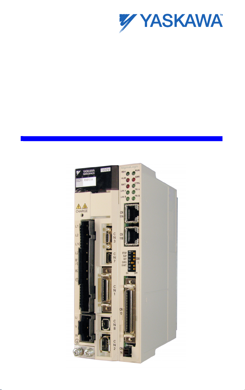
SigmaLogic™ is a single-axis machine controller option card that is
attached to a servo amplifier. The servo amplifier and controller are
factory assembled, providing a compact, all-in-one servo/controller
package with the following features:
Easy configuration with Yaskawa’s free LogicWorks™ software.
Add-on Instructions (AOI) are provided for use with Rockwell RSLogic
5000 software.
Ethernet (100Mbps) Auto crossover switching
• EtherNet/IP
• Allows high-speed communications with PLC
Combined Amplifier/Controller I/O features
• 15 digital inputs
• 11 digital outputs
• 1 external encoder (quadrature, pulse + direction, up/down)
1.1
SigmaLogic™ Features
3
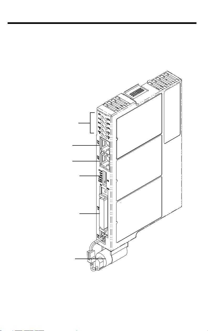
1.2
LED (10 points)
Ethernet Port A
Ethernet Port B
DIP Switch (6 points)
CN13 Port
Digital I/O
External Encoder (incremental)
3.6V Lithium Battery
(preserves retained variables,
absolute encoder offset,
and real-time clock data)
SigmaLogic™ Appearance
1.2 SigmaLogic™ Appearance
The following figure shows the external appearance of the
SigmaLogic™ controller (Note: The servo amplifier is not shown).
4
1.3 Model Number Reference
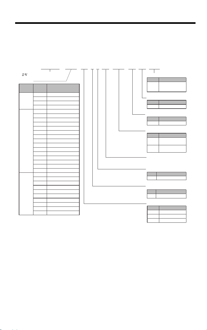
R70 A E 1 A 000 00 0 B00
Series SGDV SERVOPACK
SGDV
Current
Interface Options
Design Revision Order
Revision A
Voltage
Code Specifications
E
Option Command Type
Code Specifications
F 100 VAC
A 200 VAC
D 400 VAC
Options (hardware)
Code Specifications
002
Base-mounted
varnish (standard)
008
Single-phase
200V Input
Options (software)
Code Specifications
00 standard
Options (parameter)
Code Specifications
0 standard
Option Module
Code Specifications
B00 SigmaLogic™
Voltage
Code
Applicable Servomotor
Max. Capacity kW
100V
R70 0.05
R90 0.1
2R1 0.2
2R8 0.4
200V
R70* 0.05
R90* 0.1
1R6* 0.2
2R8* 0.4
3R8 0.5
5R5* 0.75
7R6 1.0
120
♣1.5
180 2.0
200 3.0
330 5.0
470 6.0
550 7.5
590 11
780 15
400V
1R9 0.5
3R5 1.0
5R4 1.5
8R4 2.0
120 3.0
170 5.0
210 6.0
260 7.5
280 11
370 15
Motor Type
Code Specifications
1 Rotary Servomotors
* These amplifiers can be powered with single or three-phase.
♣ SGDV-120A¡¡A008000¡¡¡, a special version of the 1.5kW
amplifier can be used for single-phase operation.
1.3.1 Model Number Designation
1.3
Model Number Reference
1.3.1 Model Number Designation
5

1.3
Model Number Reference
1.3.2 Accessory Model Numbers
1.3.2 Accessory Model Numbers
System Components
Type Model Part Number Note
Battery JZSP-BA01 Replacement
Battery Holder Kit SGDV-OZC02A Replacement (does not include battery)
CN13 Terminal Block
Conversion Kit
CN13 (Flying Leads) CFC-U-MP2Bxx
CN1 Terminal Block
Conversion Kit
Accessories/Cables
CN1 Cable (Flying
Leads)
CBK-U-MP2Bxx
SBK-U-MP2Bxx
JZSP-CSI02-x-E
xx denotes cable length (m)
A5 = 0.5
01 = 1
03 = 3
x denotes cable length (m)
A = 1 B = 2 C = 3
Ethernet Cable N/A
Communication
LogicWorks N/A
Software
Use commonly available shielded Ethernet
cable
Freeware download at
www.yaskawa.com/SigmaLogic
6

2 Specifications
2.1 General Specifications
Item Specifications
Environmental
Conditions
Mechanical
Operating
Conditions
Ambient Operating
Temperature
Ambient Storage
Temperature
Ambient Operating
Humidity
Ambient Storage
Humidity
Protection Class/
Pollution Degree
Operating Altitude 1,000 m above sea level or lower
Vibration
Resistance
Shock Resistance
Others
0 to 55°C
-20°C to +85°C
90% RH or less (with no condensation)
90% RH or less (with no condensation)
Protection class: IP10, Pollution degree: 2
An environment that satisfies the following conditions.
• Free of corrosive or explosive gases
• Free of exposure to water, oil or chemicals
• Free of dust, salts or iron dust
2
4.9 m/s
2
19.6 m/s
Free of static electricity, strong electromagnetic fields,
magnetic fields or exposure to radioactivity
2.1 General Specifications
7

2.2
SigmaLogic™ Hardware Specifications
2.2 SigmaLogic™ Hardware Specifications
Item Specification
CPU 200 MHz, 32 bit, ARM 9
SDRAM 32 MB
Memory
Operator interface
Controller
Side
(CN13)
User
I/O
ServoSide
(CN1)
Network capability EtherNet/IP
Diagnostic and configuration interface Web interface
Motion control performance
Servo-Side Safety Functions
SRAM 512 kB with battery backup
Flash 4 MB flash. Code and parameter storage.
LED
User Configuration
Network 2x 100baseTX Ethernet
Digital input 8 programmable inputs
Digital output 8 programmable outputs
Input Allocated*
Fixed Servo Alarm (ALM)
Output
Allocated*
Input
Output
10 LEDs (red and green - operating mode,
communication and error status)
6x DIP switch (operating mode and communication
configuration)
Number of Inputs: 7
Functions: The signal allocation and positive/negative
logic can be modified. Forward run prohibited (P-OT),
reverse run prohibited (N-OT), forward torque limit (/PCL), reverse torque limit (/N-CL), general-purpose
input signal (/SI0 to /SI6)
Number of Outputs: 3
Functions: The signal allocation and positive/negative
logic can be modified. Positioning completion (/COIN),
speed coincidence detection(/V-CMP), servomotor
rotation detection (/TGON), servo ready (/S-RDY),
torque limit detection (/CLT), speed limit detection
(VLT), brake (/BK), warning (/WARN), near (/NEAR)
1 controlled axis and one external position input at a
trajectory update rate of 1 kHz
/HWBB1, /HWBB2: Baseblock signal for power
module
EDM1: Status monitor (fixed output) of built-in safety
circuit
* Allocated I/O can also be used as programmable I/O if the output functions are disabled.
8
3 Mechanical Installation
3.1 Mounting Information
The SigmaLogic™ controller is pre-assembled to the Sigma-5 servo
amplifier by factory personnel. For more dimensional information for
mounting the entire unit to a subpanel, please refer to the Sigma-5
Product Catalog (document YEA-KAEPS80000042).
3.1 Mounting Information
9
3.2 Installation Standards
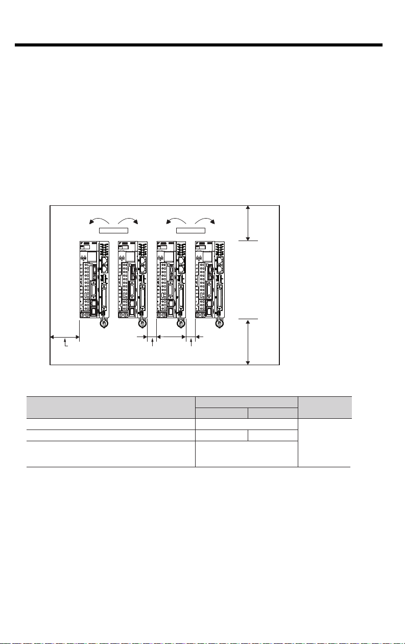
The servo amplifier must be installed in a fully enclosed metal control panel. Observe the standards
for mounting servo amplifiers in control panels, including those for the mounting servo amplifiers side
by side in one control panel as shown in the following illustration.
• Servo Amplifier Mounting Orientation
Mount the servo amplifier vertically to the wall, with the fr
ont panel (the side with the panel operator
display)
facing out.
• Cooling
Refer to the following diagram and leave sufficient space for cooling by fans and natural convection.
• Mounting Servo Amplifiers Side by Side in a Control Panel
Leave sufficient space on each side and at the top and the bottom of each servo amplifier. The
width on each side varies in accordance with the models of the servo amplifiers used.
Also install cooling fans above the servo amplifiers to disperse local pockets of warmer air around
the servo amplifiers.
• Inside the Control Panel
The conditions inside the control panel should be the same as the environmental conditions of
the servo amplifier. Refer to the environmental conditions in 2.1 General Specifications
.
• During Operation
Do not touch the connectors or IO cables during operation if the panel door is open.
.
30 mm or more
40 mm or more
40 mm or more
Fan Fan
Width varies with
servo amplifier model
Servo Amplifier Model SGDV-
Side
Top and bottom
Left Right
R70F, R90F, 2R1F, R70A, R90A, 1R6A, 2R8A 1 mm or more
40 mm or more
2R8F, 3R8A, 5R5A, 7R6A 1 mm or more 10 mm or more
120A, 180A, 200A, 330A, 470A, 550A, 590A, 780A,
1R9D, 3R5D, 5R4D, 8R4D, 120D, 170D, 210D, 260D,
280D, 370D
10 mm or more
3.2 Installation Standards
10
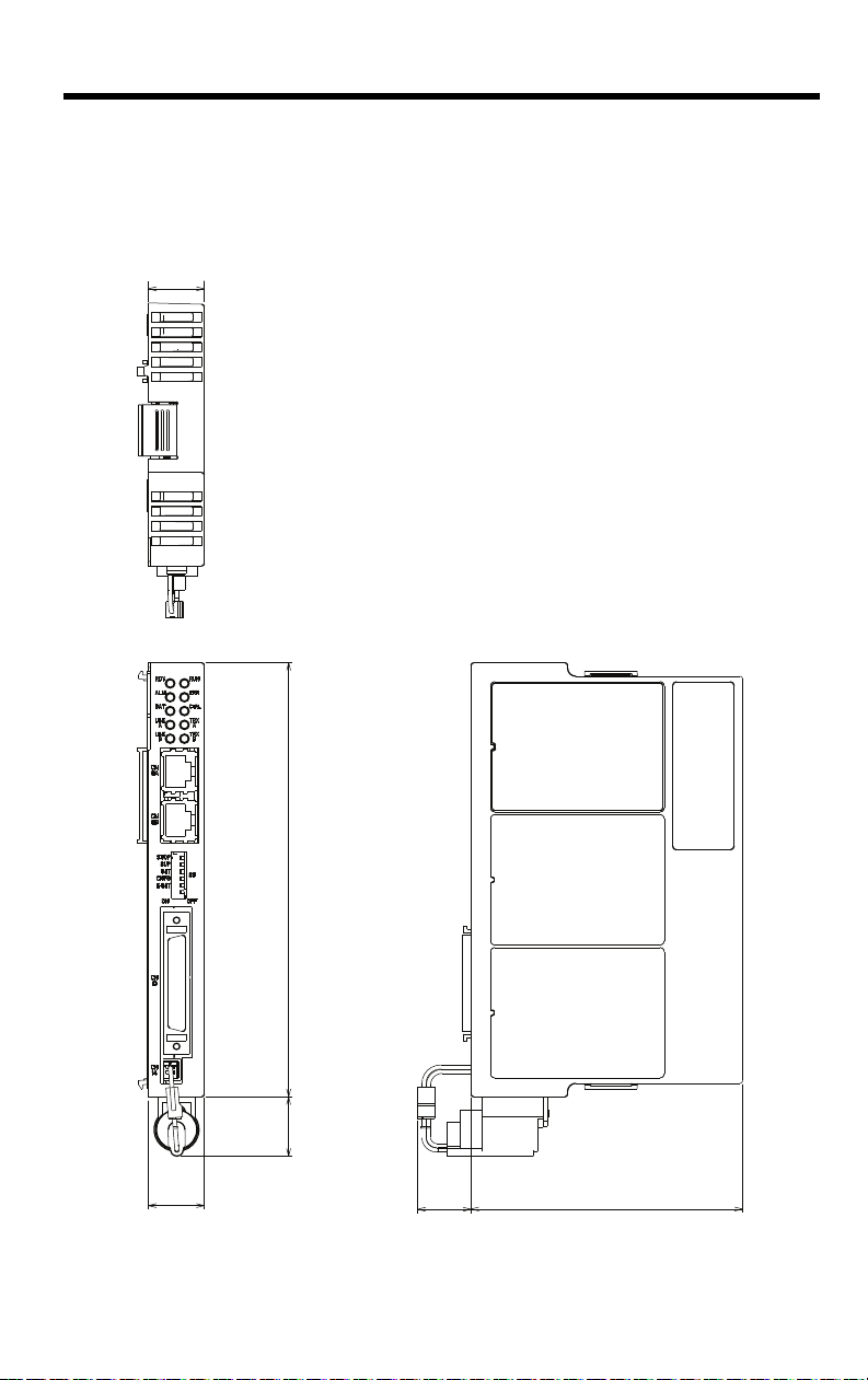
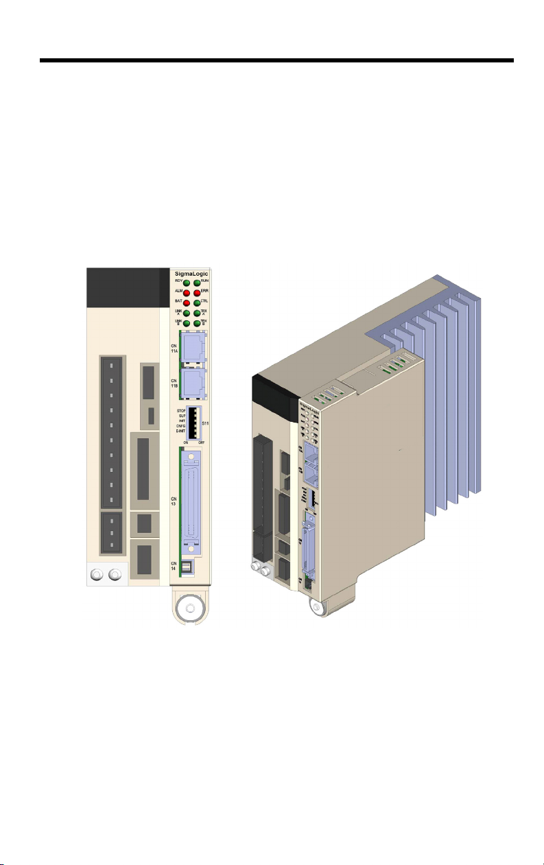
3.3 Dimensions
20
160
(22)
97
(20)
Dimensions in mm.
20
SigmaLogic
3.3.1 SigmaLogic™ Controller
3.3 Dimensions
3.3.1 SigmaLogic™ Controller
11

3.3 Dimensions
3.3.1 SigmaLogic™ Controller
This page left intentionally blank
12
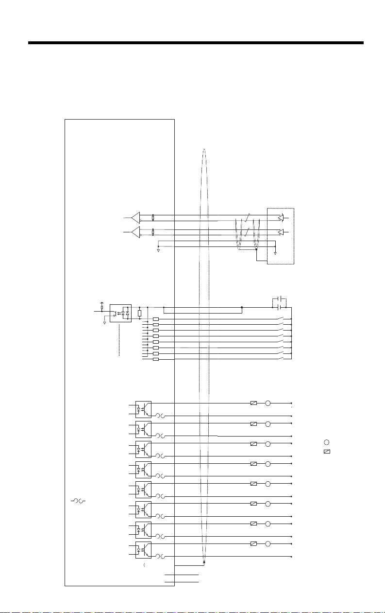
4 Inputs/Outputs
L
Load
NOTE: For a more detailed circuit drawing, see section 4.4.2.
External Fuse
(installed by
customer)
Pulse
Generator
FG
External Input
Signal
4
5
29
30
6
31
13
38
14
15
16
17
39
40
41
42
PA+
PA-
PB+
PBGND
GND
DICOM
DICOM
DI_00
DI_01
DI_02
DI_03
DI_04
DI_05
DI_06
DI_07
+5V
Encoder
Interface
Digital
Input
Digital
Output
Polyswitch Device:
A self-resetting
fuse if excessive
current is drawn
from the output
FG Connector Shell)
CN13
21
11
DO_00+
DO_00-
46
36
DO_01+
DO_01-
22
12
DO_02+
DO_02-
47
37
DO_03+
DO_03-
23
18
DO_04+
DO_04-
48
43
DO_05+
DO_05-
24
19
DO_06+
DO_06-
49
44
* DO_07+
* DO_07-
7 + Battery
32 - Battery
L
+24VDC
0V
L
+24VDC
0V
L
+24VDC
0V
L
+24VDC
0V
L
+24VDC
0V
L
+24VDC
0V
L
+24VDC
0V
L
+24VDC
0V
4.1 CN13 Connection Diagram
4.1 CN13 Connection Diagram
13

4.2
CN 13 Pin Code Description
1
2
3 n/c no connection
4 PA+ Encoder A phase +
5 PA- Encoder A phase 6 GND Encoder ground
7 BAT + SRAM Positive Battery input
8 n/c no connection
9
10
11 DO_00- Digital Output 0 12 DO_02- Digital Output 2 13 DICOM Digital Input Common
14 DI_00 Digital Input 0
15 DI_02 Digital Input 2
16 DI_04 Digital Input 4
17 DI_06 Digital Input 6
18 DO_04- Digital Output 4 19 DO_06- Digital Output 6 20 n/c no connection
21 DO_00+ Digital Output 0 +
22 DO_02+ Digital Output 2 +
23 DO_04+ Digital Output 4 +
24 DO_06+ Digital Output 6 +
25 n/c no connection
26
27
28 n/c no connection
29 PB+ Encoder B phase +
30 PB- Encoder B phase 31 GND Encoder ground
32 BAT - SRAM Negative Battery input
33 n/c no connection
34
35
36 DO_01- Digital Output 1 37 DO_03- Digital Output 3 38 DICOM Digital Input Common
39 DI_01 Digital Input 1
40 DI_03 Digital Input 3
41 DI_05 Digital Input 5
42 DI_07 Digital Input 7
43 DO_05- Digital Output 5 44 DO_07- Digital Output 7 45 n/c no connection
46 DO_01+ Digital Output 1 +
47 DO_03+ Digital Output 3 +
48 DO_05+ Digital Output 5 +
49 DO_07+ Digital Output 7 +
50 n/c no connection
CN13 Connection Description
4.2 CN13 Connection Description
Numerical
n/c no connection
n/c no connection
n/c no connection
n/c no connection
14
n/c no connection
n/c no connection
n/c no connection
n/c no connection

4.3 External Encoder Interface
4.3 External Encoder Interface
Item Specification
Number of
channels
Input circuit
Counter modes
Two RS-422 compatible inputs are provided for encoder phases A and
B.
One channel (Phase A, Phase B)
Phase A & B: 5V differential input (RS-422 compatible), non-insulated.
Maximum frequency 4MHz.
Quadrature, pulse and direction, up/down
CN13 Connector
R
R
4
PA+
5
PA-
29
PB+
30
PB-
6
GND
31
GND
Phase A
Phase B
Pulse generator
+5V
0V
+5V
0V
Encoder Input Circuit
15

4.4 Digital I/O
4.4.1 Inputs
4.4 Digital I/O
4.4.1 Inputs
• 8 general purpose
• Optically isolated
• 24 V @ 5 mA
• Entire bank is configurable as either current sinking or sourcing via
connection of common
16
Digital Input Circuit
To configure all controller inputs as sinking, wire +24VDC to pins 13
and 38. To configure all controller inputs as sourcing, wire 0VDC to
pins 13 and 38. Refer to diagram in Section 5.1.

4.4.2 Outputs
0V
Relay
5 to 24 VDC
SERVOPACK
• 8 general purpose
• Optically isolated
• 24 V @ 50 mA
• Current source or sink (connection to both emitter and collector are
provided)
Connection Examples of Output Circuits
• Relay Circuit Example
• Line Receiver Circuit Example
4.4 Digital I/O
4.4.2 Outputs
SERVOPACK
5 to 12 VDC
17

4.5 CN1 I/O
4.4.2 Outputs
4.5 CN1 I/O
CN1 includes seven digital inputs and three digital outputs that can
be monitored and controlled by the SigmaLogic™.
Control power supply
for sequence signal
Forward run prohibited
(Prohibited when OFF)
Reverse run prohibited
(Prohibited when OFF)
Command option
module input 3
Command option
module input 4
Command option
module input 5
Command option
module input 6
General-purpose input 0
Backup battery
(2.8 to 4.5 V)
Photocoupler output
Max. operating voltage: 30 VDC
Sigma-5 SGDV Servo Amp
CN1
3.3kΩ
6
*
3
*
4
*
4
*
4
*
4
+24V
/SI1
7
/SI2
8
/SI3
9
/SI4
10
/SI5
11
12
/SI6
/SI0
13
BAT+
*
2
14
BAT-
15
*
1
Max. operating current: 50 mA DC
ALM+
3
Servo alarm output
(OFF for an alarm)
ALM-
4
SO1+ / BK+
1
2
23
24
25
26
17
18
19
20
21
22
16
SO1- / BK-
/SO2+
/SO2-
/SO3+
/SO3-
/PAO
/PBO
/PCO
General-purpose outputs
PAO
PBO
PCO
SG
Brake output
(Brake released when ON)
Encoder output
pulses phase A
Encoder output
pulses phase B
Encoder output
pulses phase C
Signal ground
Applicable line
receiver
SN75ALS175
manufactured by
Texas Instruments
or an MC3486
equivalent
18

5 DIP Switches
5.1 Switch Settings
STOP
SUP
INT
CNFG
EINIT
DHCP
S11
NO
5.1 Switch Settings
Switch Name Setting Operating Mode
User program execution
ON
STOP
1
2
SUP
INIT
3
4
CNFG
5
E-INIT
6
DHCP
inhibited
OFF Normal operation
Firmware programming
ON
mode
OFF Normal operation
SRAM/clock initialization
ON
and configuration bypass
mode
OFF Normal operation
ON Normal operation
Do not set (reserved for
OFF
future use)
Force Ethernet address
setting for Port A to
ON
192.168.1.1 and Port B
to 192.168.2.1
OFF Normal Operation
DHCP-configured IP
ON
settings
Manually-configured IP
OFF
settings
Setting for
Normal
Operation
OFF
OFF
OFF
ON
OFF
OFF
Details
Inhibits user program execution
Enables SigmaLogic firmware programming.
(See Section 11)
Set to ON to bypass the stored configuration
(e.g. in case of a configuration problem that
prevents controller startup) or to initialize the
SRAM contents and clock settings after
backup power has been lost (See Section
7.1).
Always set to ON
Enables use of the default Ethernet
addresses
Enables use of DHCP for IP setting
configuration
19

5.1 Switch Settings
20
This page left intentionally blank

6 LED Outputs
RDY
ALM
BAT
RUN
ERR
CTRL
LINK
A
LINK
B
TRX
A
TRX
B
The following table shows the indicators that show the operating
status of the controller and error information.
Indicator Color Status
RDY
RUN
ALM
ERR
CTRL
BAT
TRX A
LINK A
TRX B
LINK B
Green
Green
Red
Red
Green
Red
Green
Green
Green
Green
6 LED Outputs
Lit during normal operation.
Lit during execution of user program.
Lit when alarm occurs.
Lit when malfunction occurs.
Lit when option card is communicating to the
servo amplifier.
Lit during battery alarm.
Lit during Ethernet CN11A activity.
Lit during Ethernet CN11A link up.
Lit during Ethernet CN11B activity.
Lit during Ethernet CN11B link up.
21

6 LED Outputs
This page left intentionally blank
22

7 Battery
Option Case
(snaps off unit)
Screw
Battery
Metal plate for
connection
Battery Holder
1
2
3
+
-
7.1 Battery Installation
A 3.6V lithium battery must be used to retain SRAM data in the
controller when the power is off. SRAM will last for one hour without
the battery connected. The battery power can be applied through the
battery connector (CN14), or through the I/O connector (CN13 pins
7[+] & 32[-]). The battery is necessary for preserving retained
variables, absolute encoder offset, and real-time clock data.
7.1 Battery Installation
To initialize the non-volatile memory and clock settings after a battery
is attached for the first time (or any time backup power has been lost),
use the following procedure.
1. Power off the SigmaLogic™.
2. Set the “INIT” switch (S11) to ON.
3. Power on the SigmaLogic™ and wait for the “RDY” LED to
illuminate.
4. Power off the SigmaLogic™.
5. Set the “INIT” switch (S11) to OFF.
23

7.1 Battery Installation
Battery Holder Installation Instructions:
1. Remove the plastic case from the
controller by pressing the tabs at the
top and bottom.
2. Insert the tab of the metal plate
into the last vent slot on the bottom
front of the case as shown.
3. Line up the hole in battery holder
with the hole in the metal plate and
secure the battery holder with the
screw provided.
4. Attach the extension cable to the
battery and place the battery into the
battery holder with the cable facing
forward.
5. Attach the plastic case to the
controller.
24
6. Plug the battery extension cable
into the battery connector (CN14).

8 Ethernet
Ethernet
8.1 Connectivity Information
The SigmaLogic™ controller supports 100MB speeds exclusively.
Two separate networks are possible using both CN11A and CN11B.
A default gateway can be specified only for the network attached to
CN11A.
8.2 Ethernet Connector Details
Ethernet Connector Specification and Pin Array
The following table provides the Ethernet connector specifications.
8.1 Connectivity Information
Connector
Name
Ethernet
Number
of Pins
8 RJ-45 CAT5 Socket RJ-45 CAT5 Plug Pulse Engineering
Module Side Cable Side Manufacturer
Connector Model
The following table provides Ethernet connector pin array / indicator
light details.
Pin Number Signal Name Description
1TXD+
2TXD-
3RXD+
4–
5–
6RXD-
7–
8–
Transmitted data + side
Transmitted data – side
Received data + side
–
–
Received data – side
–
–
25

8.3 Ethernet Cable
8.3 Ethernet Cable
For the Ethernet cable, use a twisted pair cable with RJ-45
connector. Yaskawa strongly recommends the use of shielded
ethernet cables. Ethernet ports are capable of auto-crossover, so
crossover cables are not necessary.
8.4 Ethernet Connection Examples
Connection Example 1 (When using a repeater HUB)
Sigma-5 with SigmaLogic
SigmaLogic
Station*
Station*
26
100Base-TX
Up to 100m
Up to 100m
Specification
Cable Length between Node-HUB 100 m or less
Cable Length between HUBs 100 m or less
Number of HUBs between Nodes Unlimited
100Base-TX
Ethernet Switch
Item
Up to 100m
Up to 100m
Up to 100m
Station*Station*
Up to 100m
100Base-TX
Ethernet Switch
* Note: SigmaLogic can only be plugged into
a 100Base-TX Ethernet port.
When Connecting to a
Ethernet Switch

Connection Example 2
Model Manufacturer
E04SR301334
Seiwa Electric Mfg. Co., Ltd
8.4 Ethernet Connection Examples
Sigma-5 with SigmaLogic
SigmaLogic
100 Base-TX (up to 100m)
Note: SigmaLogic can only be plugged
into a 100Base-TX Ethernet port.
Caution
High frequency wave noise from other devices in the installation environment
may cause errors in communications. When designing a system, use protective
measures to avoid the influence of high frequency wave noise as follows:
1. Wiring
Wire Ethernet cables so that they are well-separated from other cable
systems such as the main circuit or power lines.
2. Communication system (Ethernet)
• Communicate data to a remote device.
• Yaskawa strongly recommends shielded Ethernet cables.
3. Attach a ferrite core.
This will help reduce the occurrence of electrical interference.
Recommended ferrite core:
27

8.4 Ethernet Connection Examples
100Base-TX
Ethernet Switch
LogicWorks
Sigma-5 with SigmaLogic
Core
Core
100Base-TX
Servo motor
Station*
* Note: SigmaLogic can only be plugged
into a 100Base-TX Ethernet port
SigmaLogic
Connection Example 3
28

9 Cable Diagrams
CBK-U-MP2B-XX Function Chart for SigmaLogic
I = Input, O = Output, P = Power
Pin
No.
Signal
Name
I/O Function
Pin
No.
Signal
Name
I/O Function
126
227
3 - - - 28 reserved -
4 PA+ I Phase A pulse (+) 29 PB+ I Phase B pulse (+)
5 PA- I Phase A pulse (-) 30 PB- I Phase B pulse (-)
6 GND P Encoder input ground 31 GND P Encoder input ground
7 BAT+ P Controller SRAM Battery (+) 32 BAT- P Controller SRAM Battery (-)
8 - - - 33
- - -
- - -
934
10 35
11 DO_00- O Digital output 0 (-) 36 DO_01- O Digital output 1 (-)
12 DO_02- O Digital output 2 (-) 37 DO_03- O Digital output 3 (-)
13 DICOM I Digital input common 38 DICOM I Digital input common
14 DI_00 I Digital input 0 39 DI_01 I
Digital input 1
(shared with pulse latch input)
15 DI_02 I Digital input 2 40 DI_03 I Digital input 3
16 DI_04 I Digital input 4 41 DI_05 I Digital input 5
17 DI_06 I Digital input 6 42 DI_07 I Digital input 7
18 DO_04- O Digital output 4 (-) 43 DO_05- O Digital output 5 (-)
19 DO_06- O Digital output 6 (-) 44 DO_07- O Digital output 7 (-)
20 - - - 45 - - -
21 DO_00+ O Digital output 0 (+) 46 DO_01+ O Digital output 1 (+)
22 DO_02+ O Digital output 2 (+) 47 DO_03+ O Digital output 3 (+)
23 DO_04+ O Digital output 4 (+) 48 DO_05+ O Digital output 5 (+)
24 DO_06+ O Digital output 6 (+) 49 DO_07+ O
Digital output 7 (+) (shared with
position agreement 'COIN' signal)
25 - - - 50 - - -
- - -
- - - - - -
- - -
- - -
- - -
- - -
- - -
9.1 CBK-U-MP2B-xx
Terminal Block - CN13 I/O
9.1 CBK-U-MP2B-xx
29

9.2 CFC-U-MP2B-xx
Model X =Cable Length
CFC-U-MP2B-A5 500 mm
CFC-U-MP2B-01 1000 mm
CFC-U-MP2B-03 3000 mm
Dimensions in mm
Pin
No.
Color
(Solid/Band)
Signal
Name
I/O Function
Pin
No.
Color
(Solid/Band)
Signal
Name
I/O Function
126
Analog output
227
3 RED/GRN - - -
- - -
28 GRN/RED - - -
4 BLK/BLU PA+ I Phase A pulse (+) 29 BLK/BRN PB+ I Phase B pulse (+)
5 BLU/BLK PA- I Phase A pulse (-) 30 BRN/BLK PB- I Phase B pulse (-)
6RED/BLUGND P
Encoder input
ground
31 BLU/RED GND P
Encoder input
ground
7 RED/WHT BAT + P
Controller SRAM
Battery (+)
32 W HT/RED BAT- P
Controller SRAM
Battery (-)
8 BLK/GRN - - - 33 GRN/BLK - - -
934
10 35
11 RED/YEL DO_00- O Digital output 0 (-) 36 W HT/ORG DO_01- O Digital output 1 (-)
12 RED/BRN DO_02- O Digital output 2 (-) 37 BLU/YEL DO_03- O Digital output 3 (-)
13 RED/ORG DICOM I Digital input common 38 ORG/RED DICOM I
Digital input
common
14 GRN/WHT DI_00 I Digital input 0 39 WHT/GRN DI_01 I
Digital input 1
(shared with pulse
latch input)
15 GRN/BLU DI_02 I Digital input 2 40 BLU/GRN DI_03 I Digital input 3
16 GRN/YEL DI_04 I Digital input 4 41 YEL/GRN DI_05 I Digital input 5
17 GRN/BRN DI_06 I D igital input 6 42 BRN/GRN DI_07 I Digital input 7
18 GRN/ORG DO_04- O Digital output 4 (-) 43 BLU/BRN DO_05- O Digital output 5 (-)
19 W HT/BLU DO_06- O Digital output 6 (-) 44 BLU/ORG DO_07- O Digital output 7 (-)
20 W HT/YEL - - - 45 YEL/WHT - - -
21 YEL/RED DO_00+ O Digital output 0 (+) 46 ORG/W HT DO_01+ O Digital output 1 (+)
22 BRN/RED DO_02+ O Digital output 2 (+) 47 YEL/BLU DO_03+ O Digital output 3 (+)
23 ORG/GRN DO_04+ O Digital output 4 (+) 48 BRN/BLU DO_05+ O Digital output 5 (+)
24 BLU/W HT DO_06+ O Digital output 6 (+) 49 ORG/BLU DO_07+ O
Digital output 7 (+)
(shared with position
agreement 'COIN'
signal)
25 W HT/BRN - - - 50 BRN/WHT - - -
SigmaLogic
----
----
----
----
----
----
----
----
9.2 CFC-U-MP2B-xx
Flying Lead - CN13 I/O
30

9.3 SBK-U-VBA-xx
Signal Function
1
/BK+ (/SO1+) Brake interlock output (+) (General purpose output 1 (+))
2
/BK- (/SO1-) Brake interlock output (-) (General purpose output 1 (-))
3 ALM+ Servo alarm output (+)
4 ALM- Servo alarm output (-)
56+24VIN
Control power supply for sequence signal input
7
P-OT (/SI1) Forward run prohibited input (General purpose input 1)
8
N-OT (/SI2) Reverse run prohibited input (General purpose input 2)
9
/DEC (/SI3) Zero-point return deceleration switch input (General purpose input 3)
10
/EXT1 (/SI4) External latch signal 1 input (General purpose input 4)
11
/EXT2 (/SI5) External latch signal 2 input (General purpose input 5)
12
/EXT3 (/SI6) External latch signal 3 input (General purpose input 6)
13 /SI0 General purpose input 0
14 BAT (+) Battery (+) input
15 BAT (-) Battery (-) input
16 SG Signal ground
17 PAO Phase-A pulse output (+)
18 /PAO Phase-A pulse output (-)
19 PBO Phase-B pulse output (+)
20 /PBO Phase-B pulse output (-)
21 PCO Phase-C pulse output (+)
22 /PCO Phase-C pulse output (-)
23 /SO2+ General purpose output 2 (+)
24 /SO2- General purpose output 2 (-)
25 /SO3+ General purpose output 3 (+)
26 /SO3- General purpose output 3 (-)
SGDV Mechatrolink-II type / SGDV Option type
Pin No.
SBK-U-VBA-xx Function Chart for SGDV Servo Amplifier
Note: General purpose input and output signals are shown with their default signals assigned - signal
assignment may have been changed by parameter
Terminal Block - CN1 I/O.
9.3 SBK-U-VBA-xx
31

9.4 JZSP-CSI02-x-E
/BK
+
/BK
−
ALM
+
ALM
−
–
+
24VIN
P-OT
N-OT
/DEC
/EXT1
/EXT2
/EXT3
/SI0
BAT
+
BAT
−
SG
PAO
/PAO
PBO
/PBO
PCO
/PCO
/SO2
+
/SO2
−
/SO3
+
/SO3
−
1
2
3
4
5
6
7
8
9
10
11
12
13
14
15
16
17
18
19
20
21
22
23
24
25
26
Blue
Blue
Pink
Pink
Green
Green
Orange
Orange
Gray
Gray
Blue
Blue
Pink
Pink
Green
Green
Orange
Orange
Gray
Gray
Blue
Blue
Pink
Pink
Green
Green
Red
Black
Red
Black
Red
Black
Red
Black
Red
Black
Red
Black
Red
Black
Red
Black
Red
Black
Red
Black
Red
Black
Red
Black
Red
Black
1
1
1
1
1
1
1
1
1
1
2
2
2
2
2
2
2
2
2
2
3
3
3
3
3
3
Pin No.
Wire
Color
Signal
Marking
Color
SERVOPACK End
Dots
Lead
Marker
1
2
3
4
5
6
7
8
9
10
11
12
13
14
15
16
17
18
19
20
21
22
23
24
25
26
Represents
twisted-pair
wires.
Host
Controller End
Model Cable Length
JZSP-CSI02-1-E 1000 mm
JZSP-CSI02-2-E 2000 mm
JZSP-CSI02-3-E 3000 mm
SERVOPACK End
Connector
10126-6000
EL (by Sumitomo 3M Ltd.
)
Shell
10326-52A0-008
Cable (Ivory
)
SSRFPVV-SB AWG#
28
× 13P
UL
20276
VW-1SC
L
37
.
2
14 100
+
10
-
0
3
Dia. Wire Markers
(
6
.
3
Dia.
)
Dimensions in mm
9.4 JZSP-CSI02-x-E
Flying Lead - CN1 I/O.
32

10 Firmware Upgrade
10 Firmware Upgrade
It is possible to upgrade SigmaLogic firmware in the field.
Please visit the SigmaLogic product page on www.yaskawa.com for the
latest firmware and software release information.
33

10 Firmware Upgrade
34
This page left intentionally blank

11 EMC Installation Conditions
11 EMC Installation Conditions
This section describes the recommended installation conditions that
satisfy EMC guidelines for each model of the SGDV SERVOPACK. The
conditions required for the standard type (base-mounted) of the
SERVOPACK are described. Refer to this section for other
SERVOPACK models such as the rack-mounted types as well.
This section describes the EMC installation conditions satisfied in test
conditions prepared by Yaskawa. The actual EMC level may differ
depending on the actual system’s configuration, wiring, and other
conditions. However, because this product is built-in, check that the
following conditions are still met after being installed in the user’s
product.
The applicable standards are EN55011/A2 group 1 class A, EN61800-3,
and EN61000-6-2.
Ethernet Communication Cables: Use a category 5 or higher cable with
double, aluminum tape and braided shielding according to the standard
EN50288-2-2.
35

11 EMC Installation Conditions
U, V, W
L1, L2
L1C, L2C
CN2
CN1
PE
PE
1
3
4
5
CN8
2
PC
Controller
6
CN11 A/B
SigmaLogic
Power supply:
Single-phase 100 VAC
Encoder
Servomotor
Brake
Noise
filter
Brake Power
Supply
Surge
absorber
Two turn
Two turn Two turn
Core
Core Core
Core
Core Core
Core
General
I/O
Safety unit
Clamp
ClampClamp
Clamp
Clamp
Shield box
One turn
One turn
One turn
General I/O
1
CN13
SigmaLogic
Core
Clamp
One turn
SERVOPACK
Single-phase 100 V
SGDV-FE1A ( = R70, R90, 2R1, 2R8) + SGDV-OCC02A
36
Symbol Cable Name Specification
I/O signal cable Shield cable
Safety signal cable Shield cable
Motor main circuit cable Shield cable
Encoder cable Shield cable
Main circuit cable Shield cable
Ethernet communication cable Shield cable

11 EMC Installation Conditions
U, V, W
L1, L2, L3
L1C, L2C
CN2
CN1
PE
PE
2
1
3
4
5
CN8
Power supply:
Three-phase 200 VAC
Shield box
SERVOPACK
Encoder
Servomotor
Brake
Clamp
ClampClamp
Clamp
Noise
filter
Brake Power
Supply
Surge
absorber
Two turn Two turn
Core
CoreCore
Core
Core Core
Clamp
General
I/O
Safety unit
One turn
One turn
PC
Controller
6
CN11 A/B
SigmaLogic
Core
One turn
General I/O
1
CN13
SigmaLogic
Core
Clamp
One turn
Three-phase 200 V
SGDV-AE1A ( = R70, R90, 1R6, 2R8, 3R8, 5R5, 7R6) +
SGDV-OCC02A
Symbol Cable Name Specification
I/O signal cable Shield cable
Safety signal cable Shield cable
Motor main circuit cable Shield cable
Encoder cable Shield cable
37
Main circuit cable Shield cable
Ethernet communication cable Shield cable

11 EMC Installation Conditions
U, V, W
L1, L2, L3
L1C, L2C
CN2
CN1
PE
PE
2
1
3
4
5
CN8
Power supply:
Three-phase 200 VAC
Clamp
Noise
filter
Surge
absorber
Brake Power
Supply
SERVOPACK
Shield box
One turn
Two turn
CoreCore
Clamp
Clamp
Clamp
Two turn
Safety unit
General
I/O
Core Core
Clamp
Encoder
Servomotor
Brake
PC
Controller
6
CN11 A/B
SigmaLogic
Core
One turn
General I/O
1
CN13
SigmaLogic
Core
Clamp
One turn
Three-phase 200 V
SGDV-AE1A ( = 120) + SGDV-OCC02A
38
Symbol Cable Name Specification
I/O signal cable Shield cable
Safety signal cable Shield cable
Motor main circuit cable Shield cable
Encoder cable Shield cable
Main circuit cable Shield cable
Ethernet communication cable Shield cable

11 EMC Installation Conditions
Three-phase 200 V
SGDV-AE1A ( = 180, 200, 330) + SGDV-OCC02A
Brake Power
Supply
SERVOPACK
Power supply:
Three-phase 200 VAC
General I/O
PC
Controller
5
PE
1
6
Clamp
Surge
absorber
One turn
Clamp
One turn
Noise
filter
Core
Core
Two turn
L1, L2, L3
L1C, L2C
CN13
SigmaLogic
CN11 A/B
SigmaLogic
General
I/O
CN1
Core Core
1
U, V, W
CN2
CN8
Clamp
2
Safety unit
Shield box
One turn
Core
Two turn
Clamp
Clamp
Clamp
3
4
Brake
Servomotor
Encoder
PE
Symbol Cable Name Specification
I/O signal cable Shield cable
Safety signal cable Shield cable
Motor main circuit cable Shield cable
Encoder cable Shield cable
Main circuit cable Shield cable
Ethernet communication cable Shield cable
39

11 EMC Installation Conditions
U, V, W
L1, L2, L3
L1C, L2C
B1, B2
CN2
CN1
PE
PE
1
3
4
5
CN8
2
6
7
Power supply:
Three-phase 200 VAC
Shield box
SERVOPACK
Noise
filter
Brake Power
Supply
Surge
absorber
General
I/O
Safety unit
Encoder
Servomotor
Brake
Cooling fan
Clamp
Clamp Clamp
Clamp
Clamp
Clamp Clamp
Regenerative
resistor unit
PC
Controller
8
CN11 A/B
SigmaLogic
Core
One turn
General I/O
1
CN13
SigmaLogic
Core
Clamp
One turn
Three-phase 200 V
SGDV-AE1A ( = 470, 550, 590, 780) + SGDV-OCC02A
40
Symbol Cable Name Specification
I/O signal cable Shield cable
Safety signal cable Shield cable
Motor main circuit cable Shield cable
Encoder cable Shield cable
Main circuit cable Shield cable
Regenerative resistor unit cable Non-shield cable
Cooling fan cable Shield cable
Ethernet communication cable Shield cable

11 EMC Installation Conditions
U, V, W
L1, L2, L3
24 V, 0 V
CN2
CN1
PE
PE
1
2
3
6
5
CN8
4
SERVOPACK
Brake Power
Supply
General I/O
Safety unit
Encoder
Servomotor
Brake
Shield box
Clamp
Clamp
Core
Core
Clamp
Core
Core
Clamp
Noise
filter*
3
Core Core
Surge
absorber
Surge
absorber
Core
Noise
filter*
2
Control
power
supply
24 VDC*
1
Clamp
Clamp Clamp
One turn
One turn
Two turnTwo turn
One turn
Power supply:
Single-phase
200 VAC
Power supply:
Three-phase
400 VAC
PC
Controller
7
CN11 A/B
SigmaLogic
Core
One turn
General I/O
1
CN13
SigmaLogic
Core
Clamp
One turn
Three-phase 400 V
SGDV-DE1A ( = 1R9, 3R5, 5R4, 8R4, 120, 170)
+ SGDV-OCC02A
Symbol Cable Name Specification
I/O signal cable Shield cable
Safety signal cable Shield cable
Motor main circuit cable Shield cable
Encoder cable Shield cable
Control power cable Shield cable
Main circuit cable Shield cable
Ethernet communication cable Shield cable
* 1. Products that have received CE marking are recommended for the 24 VDC power supply.
* 2. Install the following noise filter on the power line between the single-phase 200 V power
supply and the 24 VDC power supply.
Model number: FN2070-6/07 (SCHAFFNER).
* 3. For more information on this filter, refer to Sigma-5 Product Catalog
(YEA-KAEPS80000042).
41

11 EMC Installation Conditions
U, V, W
L1, L2, L3
24 V, 0 V
CN2
CN1
PE
PE
1
2
3
6
5
CN8
B1, B2
7
4
Power supply:
Single-phase
200 VAC
Power supply:
Three-phase
400 VAC
Clamp
Surge
absorber
Surge
absorber
Clamp
Noise
filter*
2
Noise
filter*
3
Brake Power
Supply
Shield box
Control
power
supply
24 VDC*
1
SERVOPACK
Encoder
Servomotor
Brake
Clamp
Clamp
Clamp
General I/O Safety unit
Clamp Clamp
Regenerative
resistor unit
PC
Controller
8
CN11 A/B
SigmaLogic
Core
One turn
General I/O
1
CN13
SigmaLogic
Core
Clamp
One turn
Three-phase 400 V
SGDV-DE1A ( = 210, 260, 280, 370) + SGDV-OCC02A
42
Symbol Cable Name Specification
I/O signal cable Shield cable
Safety signal cable Shield cable
Motor main circuit cable Shield cable
Encoder cable Shield cable
Control power cable Shield cable
Main circuit cable Shield cable
Regenerative resistor unit cable Non-shield cable
Ethernet communication cable Shield cable
* 1. Products that have received CE marking are recommended for the 24 VDC power supply.
* 2. Install the following noise filter on the power line between the single-phase 200 V power
supply and the 24 VDC power supply.
Model number: FN2070-6/07 (SCHAFFNER).
* 3. For more information on this filter, refer to Sigma-5 Product Catalog
(YEA-KAEPS80000042).

11 EMC Installation Conditions
Host controller side
Ground plate
Cable
Cable
clamp
Shield (cable sheath stripped)
Fix and ground the cable shield
using a piece of conductive metal.
Remove paint on mounting surface.
Attachment Methods of Ferrite Cores
One turn Two tur n
Cable
Ferrite core
Cable
Ferrite core
Recommended Ferrite Core
Cable Name Ferrite Core Model Manufacturer
Motor main circuit cable ESD-SR-250 NEC TOKIN Corp.
Recommended Noise Filter and Surge Absorber
For more information on recommended noise filters and surge absorbers, refer
to Sigma-5 Product Catalog. (YEA-KAEPS800000 42)
Fixing the Cable
Fix and ground the cable shield using a piece of conductive metal.
Example of Cable Clamp
Shield Box
A shield box, which is a closed metallic enclosure, is effective as reinforced
shielding against electromagnetic interference (EMI) from SERVOPACKs. The
structure of the box should allow the main body, door, and cooling unit to be
attached to the ground. The box opening should be as small as possible.
Note: Do not connect the digital operator and the analog monitor cable to the
SERVOPACK during operations. Connect them only when the machinery is
stopped during maintenance.
43

11 EMC Installation Conditions
44


IRUMA BUSINESS CENTER (SOLUTION CENTER)
480, Kamifujisawa, Iruma, Saitama, 358-8555, Japan
Phone: 81-4-2962-5696 Fax: 81-4-2962-6138
YASKAWA ELECTRIC CORPORATION
New Pier Takeshiba South Tower, 1-16-1, Kaigan, Minatoku, Tokyo, 105-6891, Japan
Phone: 81-3-5402-4511 Fax: 81-3-5402-4580
http://www.yaskawa.co.jp
YASKAWA AMERICA, INC.
2121 Norman Drive South, Waukegan, IL 60085, U.S.A.
Phone: (800) YASKAWA (800-927-5292) or 1-847-887-7000 Fax: 1-847-887-7370
http://www.yaskawa.com
YASKAWA ELÉTRICO DO BRASIL COMÉRCIO LTDA.
Avenda Fagundes Filho, 620 Bairro Saude, São Paulo, SP04304-000, Brasil
Phone: 55-11-3585-1100
http://www.yaskawa.com.br
YASKAWA ELECTRIC EUROPE GmbH
Hauptstraβe 185, 65760 Eschborn, Germany
Phone: 49-6196-569-300 Fax: 49-6196-569-398
YASKAWA ELECTRIC UK LTD.
1 Hunt Hill Orchardton Woods, Cumbernauld, G68 9LF, United Kingdom
Phone: 44-1236-735000
YASKAWA ELECTRIC KOREA CORPORATION
7F, Doore Bldg. 24, Yeoido-dong, Youngdungpo-Ku, Seoul, 150-877, Korea
Phone: 82-2-784-7844
YASKAWA ELECTRIC (SINGAPORE) PTE. LTD.
151 Lorong Chuan, #04-01, New Tech Park, 556741, Singapore
Phone: 65-6282-3003
YASKAWA ELECTRIC (SHANGHAI) CO., LTD.
No. 18 Xizang Zhong Road, Room 1702-1707, Harbour Ring Plaza, Shanghai, 200001, China
Phone: 86-21-5385-2200
YASKAWA ELECTRIC (SHANGHAI) CO., LTD. BEIJING OFFICE
Room 1011A, Tower W3 Oriental Plaza, No. 1 East Chang An Ave.,
Dong Cheng District, Beijing, 100738, China
Phone: 86-10-8518-4086
YASKAWA ELECTRIC TAIWAN CORPORATION
9F, 16, Nanking E. Rd., Sec. 3, Taipei, Taiwan
Phone: 886-2-2502-5003
Fax: 55-11-5581-8795
Fax: 44-1236-458182
Fax: 82-2-784-8495
Fax: 65-6289-3003
Fax: 86-21-5385-3299
Fax: 86-10-8518-4082
Fax: 886-2-2505-1280
MANUAL NO.
Published in U.S.A
YAI-SIA-SL-7A
September, 2014
 Loading...