

Page 1

Sigma II Servo System Product Catalog Supplement
Sigma II Servo System
Product Catalog Supplement
Page 2

Table of Contents
Product Overview............................................................................................2 ~ 7
100/200V Single-phase Sigma II Servo System
SGMAH Sigma II Servo System...................................................................9 ~ 25
SGMPH Sigma II Servo System.................................................................27 ~ 43
SGMPH Sigma II Gearmotor System.........................................................45 ~ 54
SGDH Sigma II Servo Amplifier................................................................95 ~ 123
200V Three-phase Sigma II Servo System
SGMGH Sigma II Servo System ................................................................55 ~ 66
SGMGH Sigma II Gearmotor System.........................................................67 ~ 81
SGMSH Sigma II Servo System.................................................................83 ~ 93
SGDH Sigma II Servo Amplifier................................................................95 ~ 123
400V Three-phase Sigma II Servo System
SGMGH Sigma II Servo System ............................................................125 ~ 136
SGMSH/UH Sigma II Servo System.......................................................137 ~ 149
SGMBH Sigma II Servo System.............................................................151 ~ 162
SGDH Sigma II Servo Amplifier..............................................................163 ~ 199
1
Page 3
Product Overview
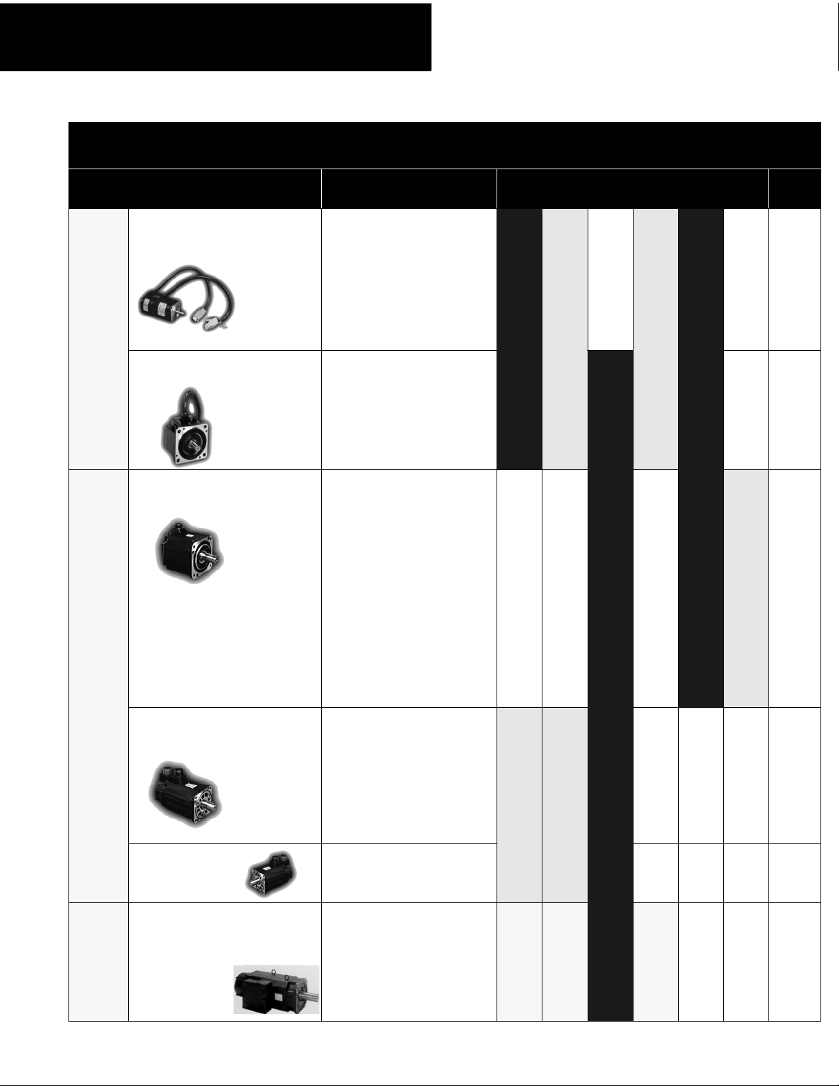
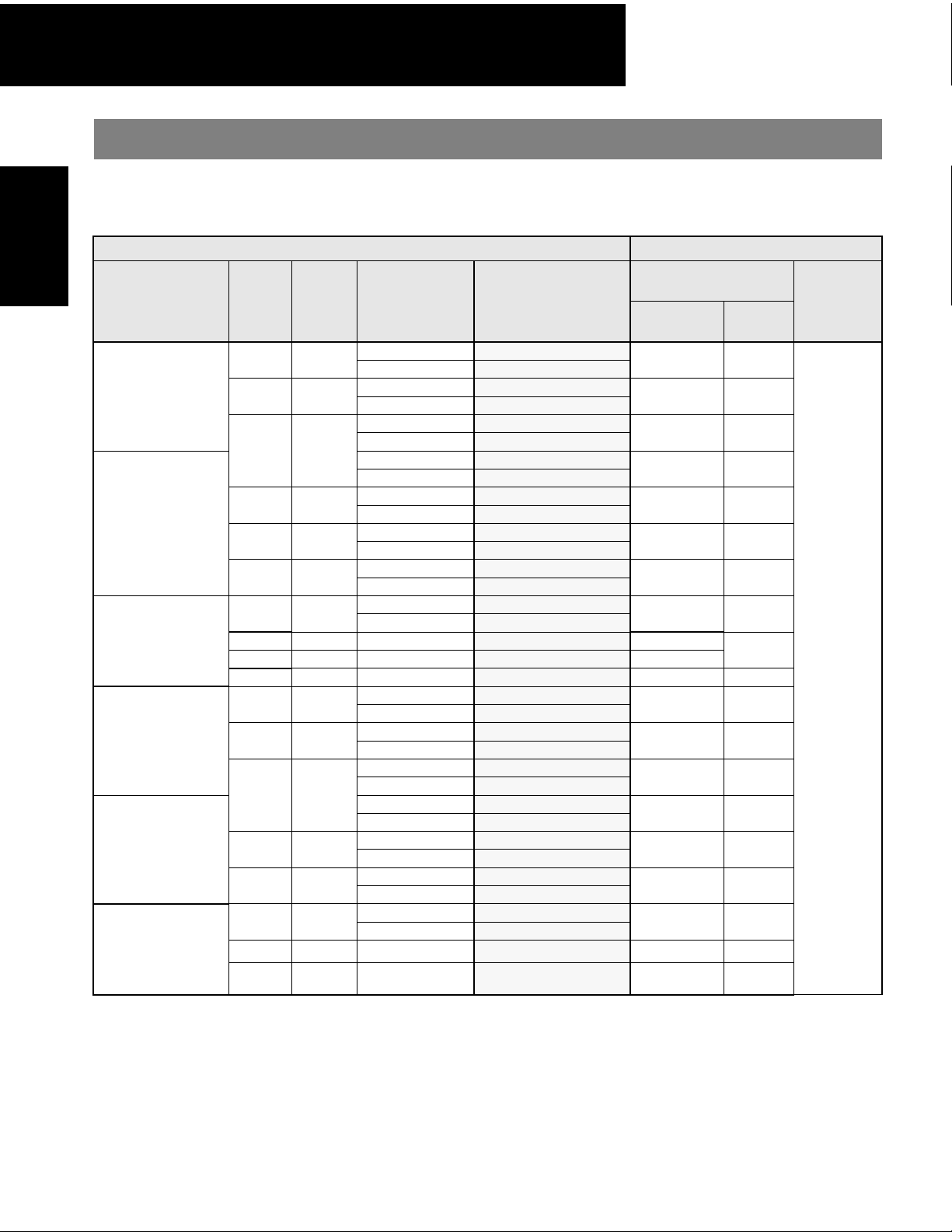
Yaskawa has a full lineup of servomotors and amplifiers. Choose the best drives for your needs and specifications.
Servomotor
Series Description Applications
Small
capacity
SGMAH
(3000rpm/5000rpm max)
SGMPH
(3000rpm/5000rpm max)
SGMGH
(1500rpm/3000rpm max)
High Speed Series
Large torque required at low
inertia.
Flat Series
Short L-length. Good for
installation in compact
spaces.
General Purpose
High speed rotation required
without load.
Robots
Chip Mounters
PCB Drilling Machines
Material Handling Equipment
Medium
Large
2
SGMSH
capacity
(3000rpm/5000rpm max)
SGMUH
(6000rpm max)
SGMBH
(2000rpm max)
capacity
High Speed Series
High torque required at low
inertia.
High Speed Series
High torque at 6000rpm.
Large kW
Chip Mounters
PCB Drilling Machines
Converting
Thermoforming
Machine Tool Feeds
Packaging Machines
Injection molding
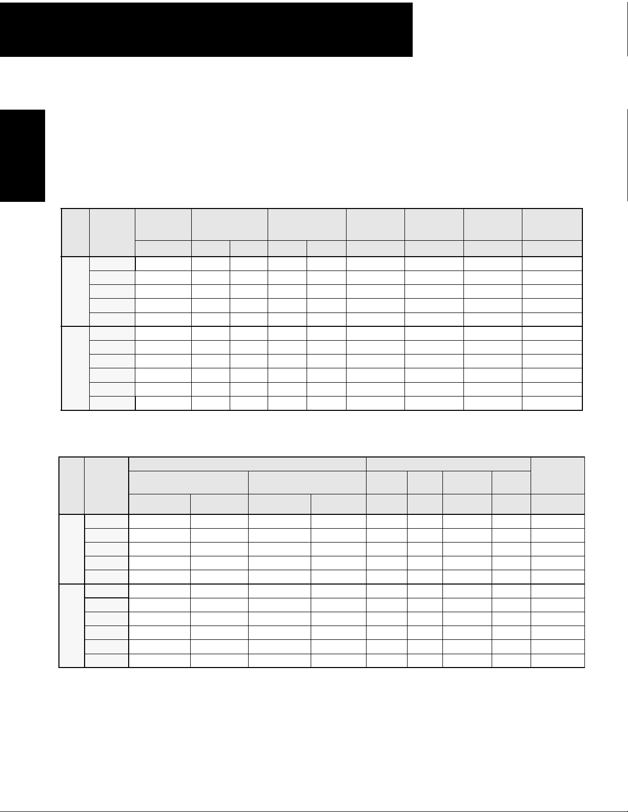
Page 4
Product Overview
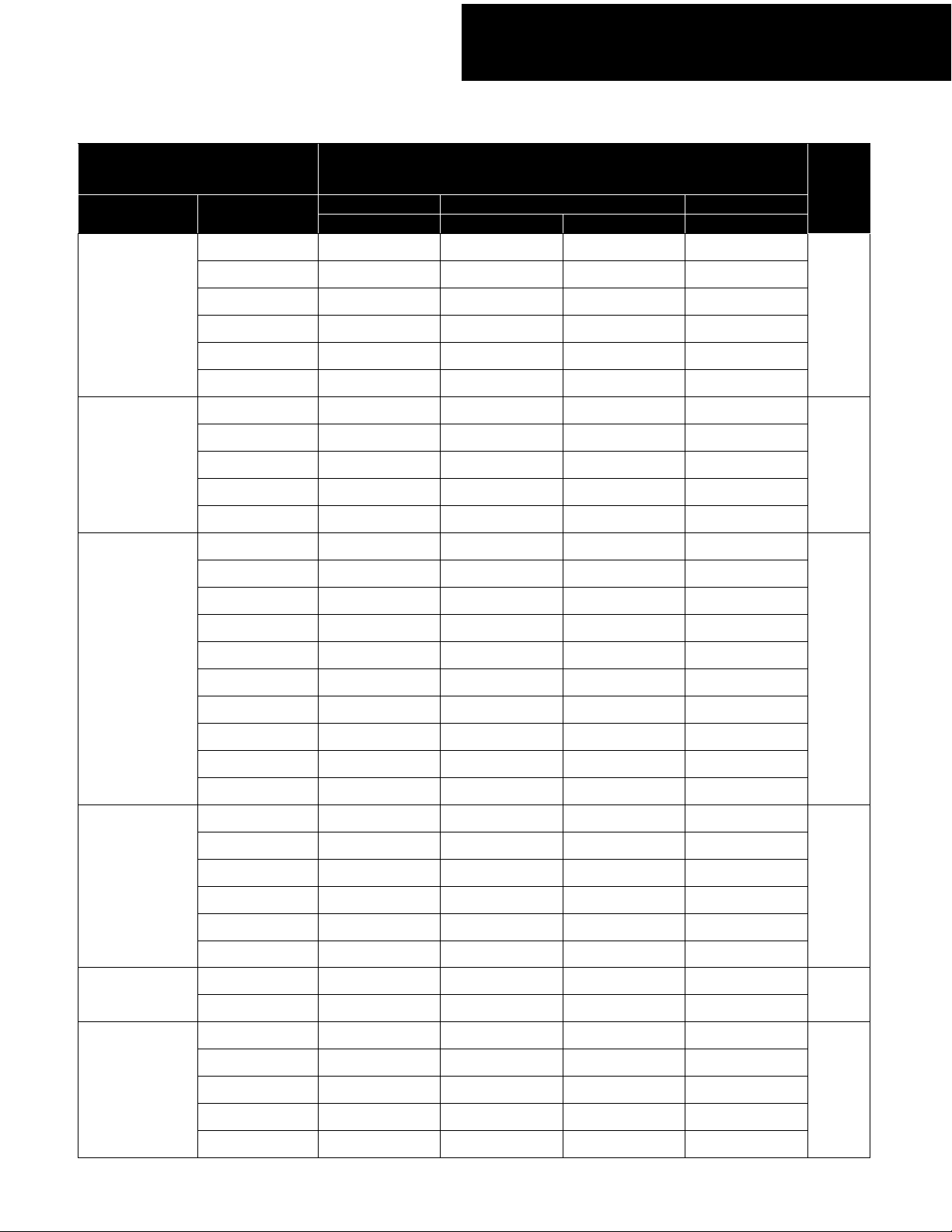
Servomotor
Peak Torque Capacity
30W A3BE A3AE — —
50W A5BE A5AE — —
up to
1,010oz • in
up to
2,027oz • in
100W 01BE 01AE — —
200W 02BE 02AE — —
400W — 04AE — —
750W — 08AE-S — —
100W 01BE 01AE — —
200W 02BE 02AE — —
400W — 04AE — —
750W — 08AE-S 08AE —
1500W — 15AE-S 15AE —
0.45kW — — 05AE 05DE
0.85kW — — 10AE 10DE
1.3kW — — 15AE 15DE
Servo Amplifier
Type SGDH-***
110V 230V 480V
Single-phase Single-phase Three-phase Three-phase
Page
11, 97
29, 97
up to
1,988in • lb
up to
422in • lb
up to
190in • lb
up to
6120in • lb
1.8kW — — 20AE 20DE
2.9kW — — 30AE 30DE
4.4kW — — 50AE 50DE
5.5kW — — 60AE 60DE
7.5kW — — 75AE 75DE
11kW — — 1AAE 1ADE
15kW — — 1EAE 1EDE
1.0kW — — 10AE 10DE
1.5kW — — 15AE 15DE
2.0kW — — 20AE 20DE
3.0kW — — 30AE 30DE
4.0kW — — 50AE 50DE
5.0kW — — 50AE 50DE
1.0 kW — — — 10DE
3.0kW — — — 30DE
22kW — — — 2BDE
30kW———3ZDE
37kW———3GDE
45kw———4EDE
57, 97,
127,
153
85, 97,
139,
153
139,
153
153,
165
55kW — — — 5EDE
3
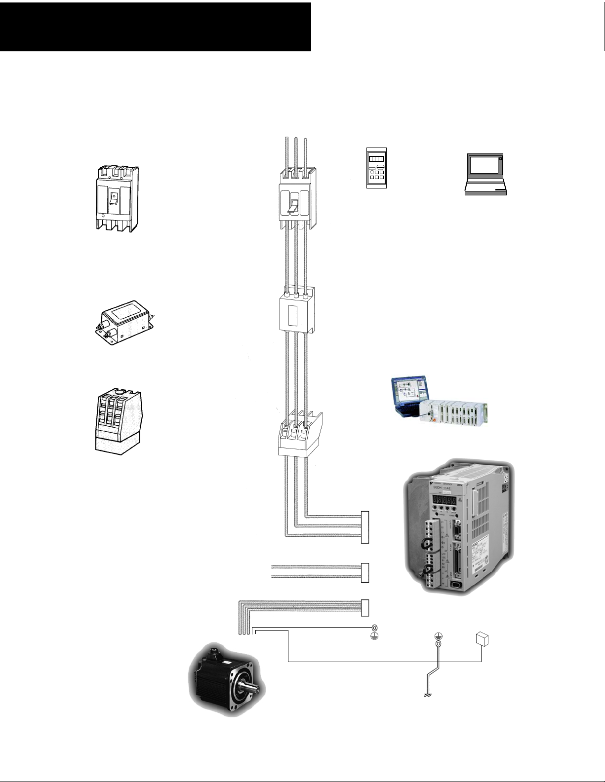
Page 5
Product Overview
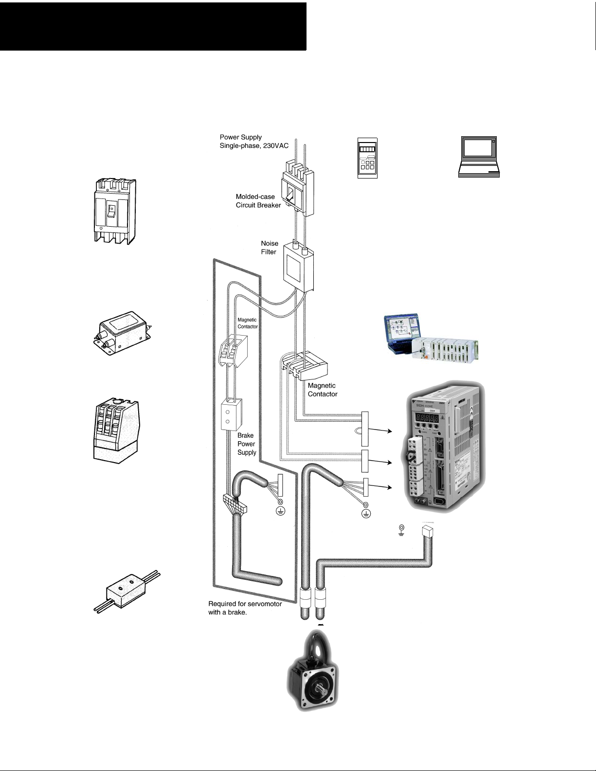
Single-phase
30W to 1500W (230VAC)
Molded-case Circuit
Breaker (MCCB)
Protects the power
line by shutting
the circuit OFF
when overcurrent
is detected.
888 88
SERVOPACK
ALARM
YASKAWA
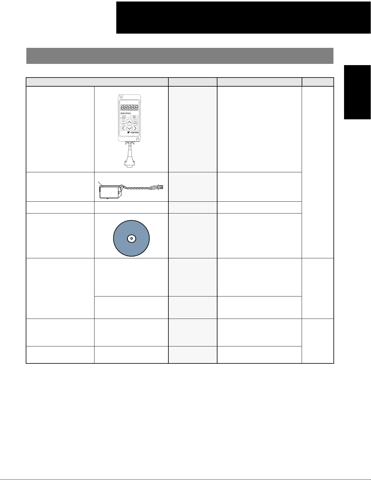
Digital Operator
(Type JUSP-OP02A-1)
.
Personal
Computer
Cable for
connecting to
servo amplifier
required.
Noise Filter (optional)
Used to eliminate external noise
from the power line.
Magnetic Contactor
Turns the servo
ON and OFF.
Install a surge
suppressor on
the magnetic
contactor.
Holding Brake
Power Supply
(customer supplied)
Used only for SGM* servomotor
with a holding brake.
Host Controller
Connect the SGDH servo amplifier to a
Yaskawa host controller or one made by
other vendors. (Analog input, pulse train input
available)
SGDH
Servo Amplifier
Type SGDH-A3AE
to -15AE-S
SGMPH Servomotor
4
Page 6
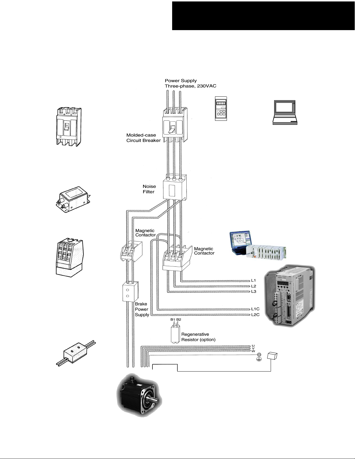
Three-phase
0.5kW to 15kW (230VAC)
Molded-case Circuit
Breaker (MCCB)
Protects the power
line by shutting
the circuit OFF
when overcurrent
is detected.
Noise Filter (optional)
Used to eliminate external noise
from the power line.
Product Overview
888 88
SERVOPACK
ALARM
YASKAWA
Digital Operator
(Type JUSP-OP02A-1)
.
Personal
Computer
Cable for
connecting to
amplifier
required.
Magnetic Contactor
Turns the servo
ON and OFF.
Install a surge
suppressor on
the magnetic
contactor.
Holding Brake
Power Supply
(customer supplied)
Used for SGM* servomotor
with a brake
Host Controller
Connect the SGDH servo amplifier to a
Yaskawa host controller or one made by
other vendors. (Analog input, pulse train input
available)
SGDH Servo Amplifier
Type SGDH-05AE to -1EAE
SGMSH Servomotor
5
Page 7
Product Overview
Three-phase
0.5kW to 55kW (480VAC)
Molded-case Circuit
Breaker (MCCB)
Protects the power
line by shutting
the circuit OFF
when overcurrent
is detected.
Noise Filter (optional)
Used to eliminate external noise
from the power line.
Power Supply
Three-phase, 480VAC
Molded-case
Circuit Breaker
Noise
Filter
888 88
SERVOPACK
ALARM
YASKAWA
Digital Operator
(Type JUSP-OP02A-1)
.
Personal
Computer
Cable for
connecting to
amplifier
required.
Magnetic Contactor
Turns the servo
ON and OFF.
Install a surge
suppressor on
the magnetic
contactor.
Control Power Supply
24V
0V
Host Controller
Connect the SGDH servo amplifier to a
Yaskawa host controller or one made by
other vendors. (Analog input, pulse train input
available)
Magnetic
Contactor
SGDH Servo Amplifier
Type SGDH-05DE to -5EDE
MP920
SGMGH Servomotor
6
Page 8
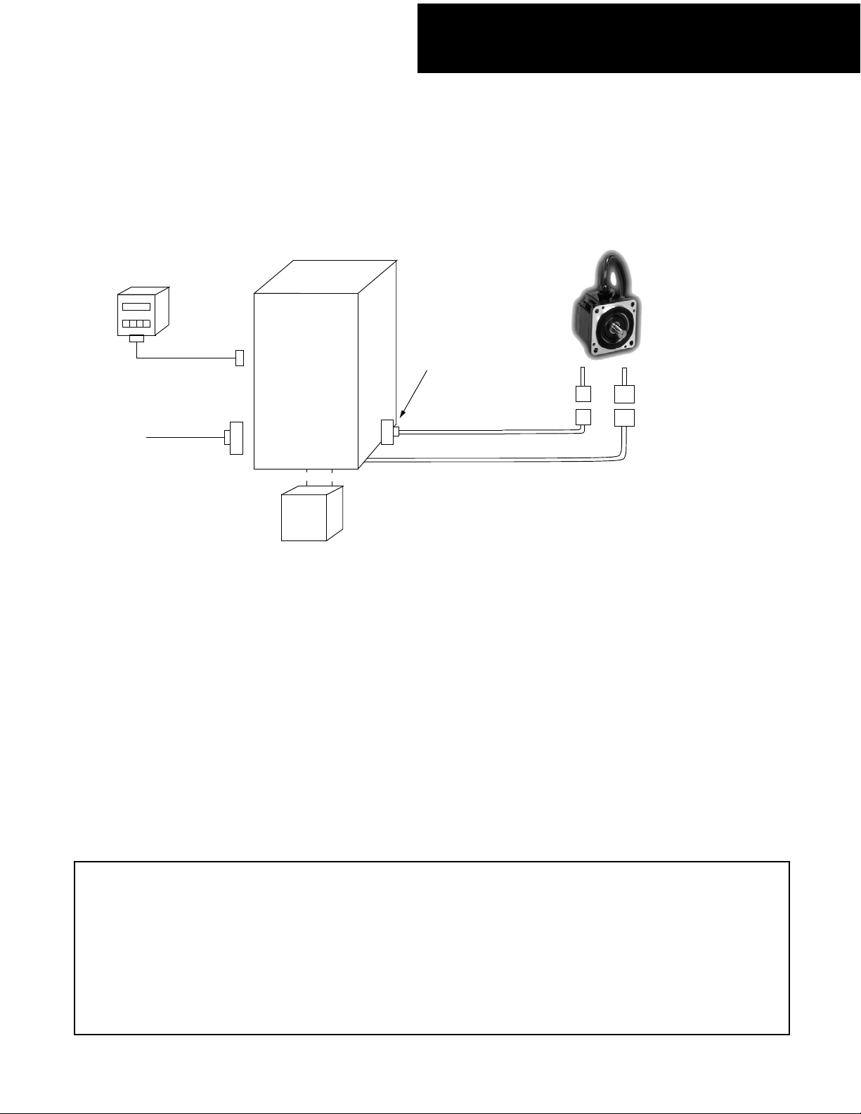
Product Overview
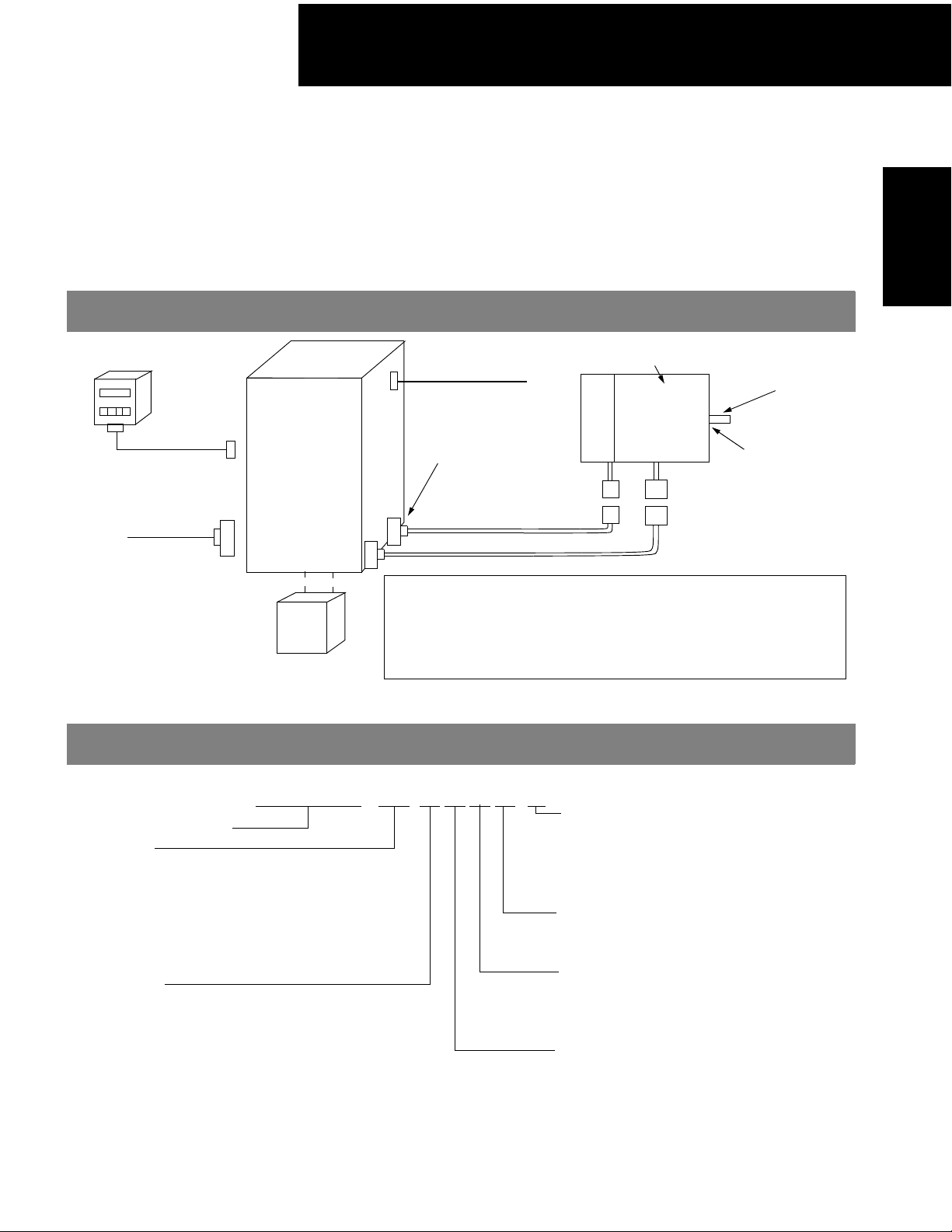
Selecting Your Sigma Servo System
For your convenience, each motor series in this selection guide includes a diagram to help
you select and identify the components necessary for your system. Each item is letter-coded
and cross-referenced in the option tables on the following pages.
Digital Operator (E)
3CN
Peripheral
Signal
Cable (E)
1CN
I/O Signal
Connector
(D)
SGDH Servo
Amplifier
(B)
Regenerative Unit (E)
Connector
Encoder Signal (D)
Encoder side
Connector (D)
2CN
Encoder Cable (C)
Motor Cable (C)
Motor side
Connector (D)
1. First, select the Sigma servomotor suited for your application using the Yaskawa Servomotor Sizing
Software or the Sigma Servomotor Data Sheets. Using the tab indicators in this guide, locate the section
describing the type of servomotor you selected.
2. Then select a compatible amplifier using the Sigma II Servo Amplifier Selection Table in the appropriate
servomotor section of this guide.
3. Yaskawa offers pre-wired power and encoder cables with correctly matched, high quality connectors
attached to permit correct interconnection. Refer to the Pre-wired Cable Selection Table to select the
correct cable assembly from the list of standard cable lengths.
4. Solder-type connectors without cables are also available. Refer to the appropriate Servomotor Connector
Selection Table to select the connector kit to be used with the selected servomotor or encoder (with or
without brake).
5. Refer to the Peripheral Device Selection Table to select peripheral equipment to be used with the servo
amplifier (i.e., digital operator, regenerative unit, software, etc.).
6. Specify technical product manual YEA-SIA-S800-32.2 on your Sigma II Servo System purchase order.
One manual is available at no charge with each purchase order. The manual can also be downloaded at
no charge from Yaskawa’s Web site at www.yaskawa.com.
Each table includes a column labeled “Item Class,” which classifies the availability of the specified option. Following are
descriptions of the codes used:
Stock: Normally 3 to 5 days lead time for most order quantities. 3 to 5 weeks maximum if temporary outages occur.
For critical lead times or requirements for larger quantity shipments, check with your Yaskawa inside sales
representative.
Limited Typically, small quantities are available from stock. These items will likely change to stock items as the
Stock: order demand increases. For critical lead times or requirements for larger quantity shipments, check with your
Yaskawa inside sales representative.
Non-Stock: Normal delivery: 12 to 16 weeks.
7
Page 9

Product Overview
NOTES:
8
Page 10
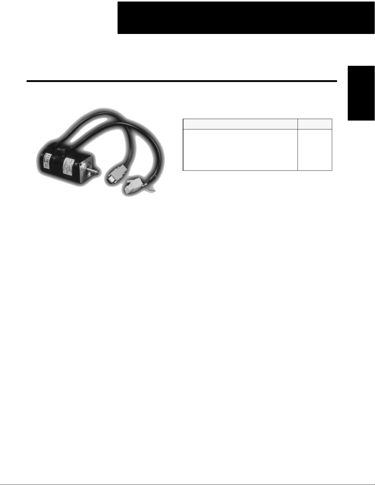
100/200V Single-phase Sigma II Servo Systems
Super High Power Rate Series
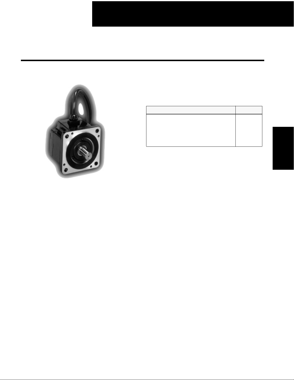
SGMAH Servomotors - With Incremental / Absolute Encoder
Rated Output: 30W, 50W, 100W,
200W, 400W, 750W
For Additional Information Page(s)
SGMAH Ratings & Specifications
SGMAH Speed/Torque Curves
SGMAH Dimensions
SGMAH Selection/Ordering Information
SGDH Ratings & Specifications
SGDH Dimensions
12
13
14 - 22
23 - 27
99 - 100
101 - 112
SGMAH
Servomotors
Design Features
1. Compact
z Small sized motor
Five frame sizes (including NEMA 23 and 34 flanges): up to 1,010oz
Smaller installation space for more compact machine designs.
2. High Speed
z High power rating
High power is achieved by minimizing the inertia of the motor
This increases the acceleration/deceleration rate and reduces positioning time
z Maximum rotation speed of 5000rpm
Increases maximum rotation speed and shortens positioning time
z Rated speed of 3,000rpm
3. Encoders (reduced wiring serial encoder)
z 13-bit (2048 ppr x 4) incremental encoder (standard)
z 16-bit (16384) absolute encoder (option)
4. Enclosure
z Totally enclosed, self-cooled IP55 (not including shaft)
z Optional shaft seals are available.
5. Application Emphasis
z Compact, high torque to inertia ratio
z Chip mounters
z PCB drilling machines
z Robots
z Conveyors
z Packaging
6. Low Noise
z Adopting the IGBT power element eliminates irritating “metallic” sounds
7. Certified International Standards
z UL, cUL recognized (File #: E165827), CE compliance
• in peak torque
9
Page 11
100/200V Single-phase Sigma II Servo Systems
Servomotor Ratings and Specifications
Servomotors
SGMAH
Time Rating: Continuous
Insulation: Class B
μ
Vibration: 15
Withstand Voltage: 1500V
Insulation Resistance: 10MΩ
Specifications are the same for either absolute or incremental encoders.
m or less
ac
minimum at
500V
DC
Enclosure: Totally-enclosed, self-cooled
Ambient Temperature: 0 to 40ºC
Ambient Humidity: 20 to 80%
(non-condensing)
Rated Rotation Speed: 3000rpm
Maximum Rotation Speed: 5000rpm
Excitation: Permanent magnet
Drive Method: Direct drive
Mounting: Flange-mounted
Applicable Encoder: 13-bit incremental
or 16-bit absolute
encoder
MOTOR
SGMAH-
System
Voltage
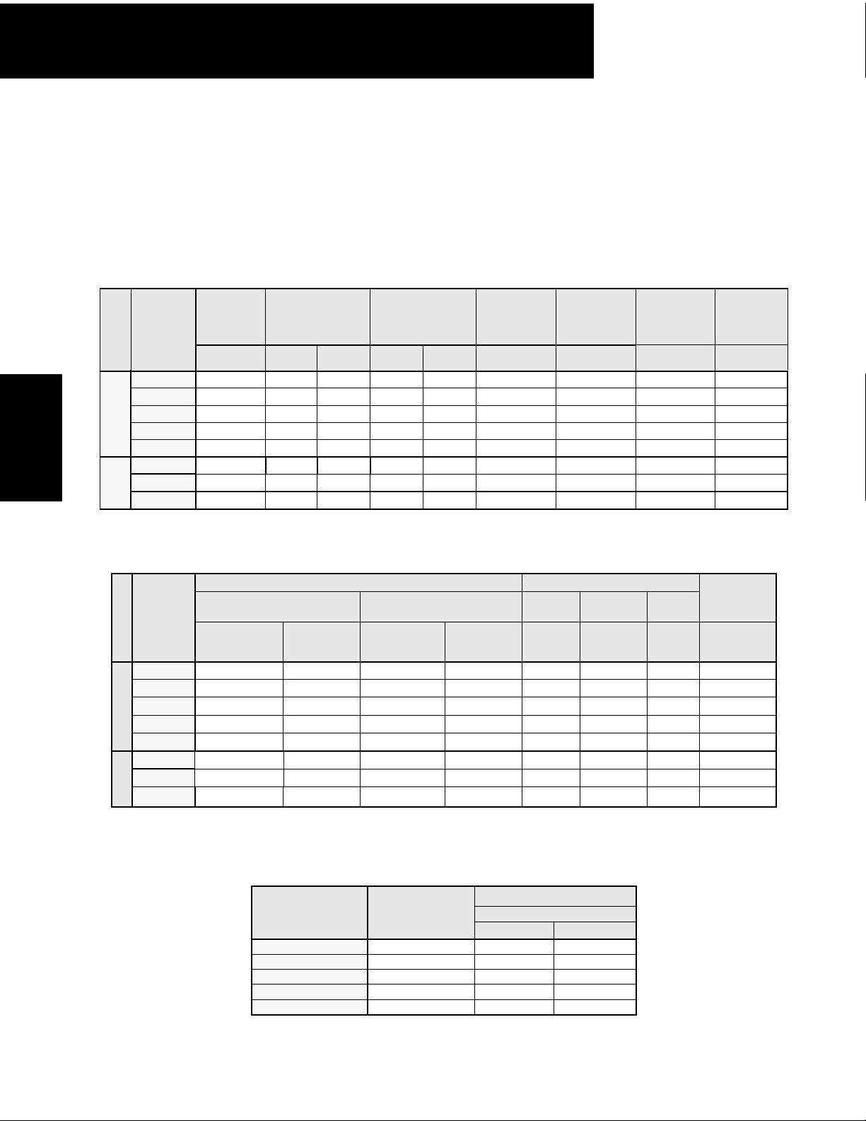
A3B 30 (0.04) 13.5 0.095 40.5 0.29 0.66 2.0 57500 3.49
A5B 50 (0.07) 22.6 0.159 67.7 0.48 0.95 2.9 72300 11.5
ac
01B 100 (0.13) 45.1 0.318 135 0.96 2.4 7.2 87400 27.8
100V
02B 200 (0.27) 90.1 0.637 270 1.91 3.0 9.0 60100 38.2
04A** 400 (0.53) 181 1.27 542 3.82 2.8 8.5 73600 93.7
A3A 30 (0.04) 13.5 0.095 40.5 0.29 0.44 1.3 57500 5.49
A5A 50 (0.07) 22.6 0.159 67.7 0.48 0.64 2.0 72300 11.5
ac
01A 100 (0.13) 45.1 0.318 135 0.96 0.91 2.8 87400 27.8
02A 200 (0.27) 90.1 0.637 270 1.91 2.1 6.5 60100 38.2
200V
04A 400 (0.53) 181 1.27 542 3.82 2.8 8.5 73600 93.7
08A 750 (1.01) 338 2.39 1010 7.1 4.4 13.4 35600 85.1
Rated
Output
W (hp) oz • in N • m oz • in N • m
Rated
Torque*
Instantaneous
Peak
Torque*
* Values when the servomotor is combined with an SGDH servo amplifier
Continuous
Rated Cur-
rent
A
rms
.
Maximum
Peak
Current
A
rms
Rated
Angular
Acceleration
2
rad/s
** When combined with an SGDH-04FE servo amplifier.
Moment of Inertia Holding Brake (at 20°C)
MOTORS
SGMAH-
System
Voltage
A3B 0.235 0.0166 0.355 0.251 6 .20 96 0.25 0.63
A5B 0.312 0.0220 0.432 0.0305 6 .20 96 0.25 0.78
ac
01B 0.515 0.0364 0.635 0.0449 6 .35 96 0.25 1.20
100V
02B 1.50 0.106 2.321 0.164 6.5 1.5 89 0.27 3.69
04A 2.45 0.173 3.271 0.231 6.5 1.5 89 0.27 3.82
A3A 0.235 0.0166 0.355 0.0251 6 .20 96 0.25 0.63
A5A 0.312 0.0220 0.432 0.0305 6 .20 96 0.25 0.78
ac
01A 0.515 0.0364 0.635 0.0449 6 .35 96 0.25 1.20
02A 1.50 0.106 2.321 0.164 6.5 1.5 89 0.27 3.69
200V
04A 2.45 0.173 3.271 0.231 6.5 1.5 89 0.27 3.82
08A 9.52 0.671 11.5 0.811 6 2.5 96 0.25 13.4
Motor without Brake Motor with Brake
oz • in • s2 × 10-3kg • m2 × 10-4oz • in • s2 × 10-3kg • m
2
× 10
-4
Capacity Torque
W N • m Ω A
Coil
Resistance
Current
Rated
Rated Power
Rate*
kW/s
Allowable
Load
Inertia*
2
kg • m
× 10
-4
* · Values apply to motors without brake.
(allowable load inertia) shows the range requiring no exterior regenerative unit. When these values are exceeded, appli-
· J
L
cation may be restricted or a regenerative unit may be required.
10
Page 12
100/200V Single-phase Sigma II Servo Systems
䍕㩷
䍕
䍕㩷
䍕㩷
䍕㩷
䍕
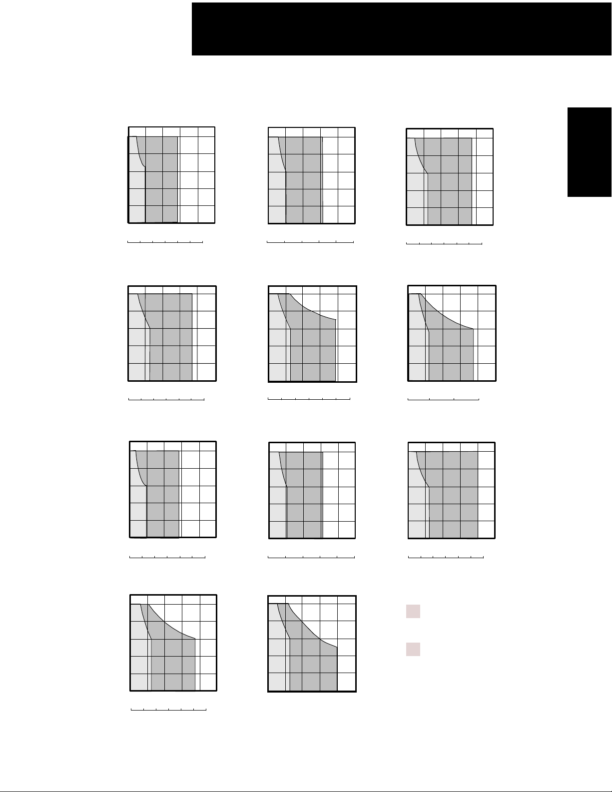
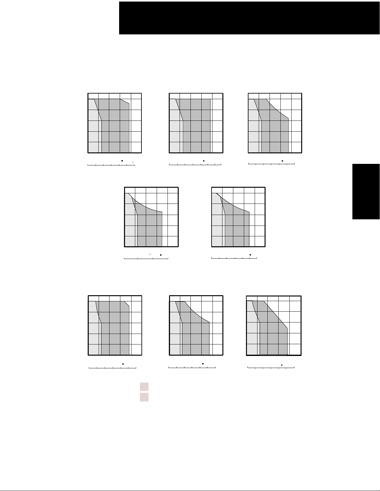
Speed / Torque Curves
200V
200V
SGMAH-A3A SGMAH-A5A SGMAH-01A
㪪㪧㪜㪜㪛㩷㩿㫉㫇㫄㪀
㪪㪧㪜㪜㪛㩷㩿㫉㫇㫄㪀
100V
100V
㪌㪇㪇㪇
㪋㪇㪇㪇
㪊㪇㪇㪇
㪘
㪉㪇㪇㪇
㪈㪇㪇㪇
㪙
㪇
㪇㩷㩷㩷㩷㩷㪇㪅㪈㩷㩷㩷㩷㪇㪅㪉㩷㩷㩷㪇㪅㪊㩷㩷㩷㪇㪅㪋
㪫㪦㪩㪨㪬㪜㩷㩿㪥㩷䍕㩷㫄㪀
㪇㩷㩷㩷㩷㩷㩷㩷㩷㩷㩷㩷㩷㩷㪉㪇㩷㩷㩷㩷㩷㩷㩷㩷㩷㩷㩷㩷㪋㪇㩷㩷㩷㩷㩷㩷㩷㩷㩷㩷㩷㪍㪇
㪫㪦㪩㪨㪬㪜㩷㩿㫆㫑㩷䍕㩷㫀㫅㪀
SGMAH-02A SGMAH08A
㪌㪇㪇㪇
㪋㪇㪇㪇
㪊㪇㪇㪇
㩷㩷㩷㩷㩷㩷㪙
㪘
㪉㪇㪇㪇
㪈㪇㪇㪇
㪇
㪇㩷㩷㩷㩷㪇㪅㪌㩷㩷㩷㩷㩷㪈㩷㩷㩷㩷㩷㪈㪅㪌㩷㩷㩷㩷㩷㪉
㪫㪦㪩㪨㪬㪜㩷㩿㪥㩷䍕䍕㩷㫄㪀
㪇㩷㩷㩷㩷㩷㩷㩷㩷㩷㩷㩷㩷㪈㪇㪇㩷㩷㩷㩷㩷㩷㩷㩷㩷㩷㪉㪇㪇㩷㩷㩷㩷㩷㩷㩷㩷㩷㪊㪇㪇
㪫㪦㪩㪨㪬㪜㩷㩿㫆㫑㩷䍕
㫀㫅㪀
㪌㪇㪇㪇
㪋㪇㪇㪇
㪊㪇㪇㪇
㪉㪇㪇㪇
㪪㪧㪜㪜㪛㩷㩿㫉㫇㫄㪀
㪈㪇㪇㪇
㪇
㪙㪘
㪇㩷㩷㩷㪇㪅㪈㪌㩷㩷㩷㪇㪅㪊㩷㩷㩷㪇㪅㪋㪌㩷㩷㪇㪅㪍
㪫㪦㪩㪨㪬㪜㩷㩿㪥㩷䍕㩷㫄㪀
㪇㩷㩷㩷㩷㩷㩷㩷㩷㪉㪇㩷㩷㩷㩷㩷㩷㩷㪋㪇㩷㩷㩷㩷㩷㩷㩷㪍㪇㩷㩷㩷㩷㩷㩷㪏㪇
㪈㪇㪇
㪫㪦㪩㪨㪬㪜㩷㩿㫆㫑㩷䍕㩷㫀㫅㪀
SGMAH-04A
5000
4000
3000
A
2000
㪪㪧㪜㪜㪛㩷㩿㫉㫇㫄㪀
1000
0
0
1
㪫㪦㪩㪨㪬㪜㩷㩿㪥㩷䍕䍕㩷㫄㪀
㩷㩷㪇㩷㩷㩷㩷㩷㩷㩷㩷㩷㩷㩷㪉㪇㪇㩷㩷㩷㩷㩷㩷㩷㩷㩷㪋㪇㪇㩷㩷㩷㩷㩷㩷㩷㩷㪍㪇㪇
㪫㪦㪩㪨㪬㪜㩷㩿㫆㫑㩷䍕
B
234
㫀㫅㪀
㪌㪇㪇㪇
㪋㪇㪇㪇
㪊㪇㪇㪇
㪉㪇㪇㪇
㪪㪧㪜㪜㪛㩷㩿㫉㫇㫄㪀
㪈㪇㪇㪇
㪇
㪇㩷㩷㪇㪅㪉㪌㩷㩷㩷㩷㪇㪅㪌㩷㩷㩷㪇㪅㪎㪌㩷㩷㩷㩷㪈
㪇㩷㩷㩷㩷㩷㩷㩷㩷㩷㩷㩷㩷㩷㪌㪇㩷㩷㩷㩷㩷㩷㩷㩷㩷㩷㪈㪇㪇㩷㩷㩷㩷㩷㩷㩷㩷㩷㪈㪌㪇
㪌㪇㪇㪇
㪋㪇㪇㪇
㪊㪇㪇㪇
㪉㪇㪇㪇
㪪㪧㪜㪜㪛㩷㩿㫉㫇㫄㪀
㪈㪇㪇㪇
㪇
㪇㩷㩷㩷㩷㩷㩷㪉㩷㩷㩷㩷㩷㩷㪋㩷㩷㩷㩷㩷㩷㩷㪍
㪏
㪇㩷㩷㩷㩷㩷㩷㩷㩷㩷㪋㪇㪇㩷㩷㩷㩷㩷㩷㩷㩷㪏㪇㪇㩷㩷㩷㩷㩷㩷㩷㩷㩷㪈㪉㪇㪇
SGMAH-A3B SGMAH-A5B SGMAH-01B
㩷㩷㩷㩷㪙㪘
㪫㪦㪩㪨㪬㪜㩷㩿㪥㩷䍕
㪫㪦㪩㪨㪬㪜㩷㩿㫆㫑㩷䍕䍕㩷㫀㫅㪀
㩷㫄㪀
㩷㩷㩷㩷㪙㪘
㪫㪦㪩㪨㪬㪜㩷㩿㪥㩷䍕䍕㩷㫄㪀
㪫㪦㪩㪨㪬㪜㩷㩿㫆㫑㩷䍕
SGMAH
Servomotors
㫀㫅㪀
㪌㪇㪇㪇
㪋㪇㪇㪇
㪊㪇㪇㪇
㪘
㪉㪇㪇㪇
㪪㪧㪜㪜㪛㩷㩿㫉㫇㫄㪀
㪈㪇㪇㪇
㪇
㪙
㪇㩷㩷㩷㩷㪇㪅㪈㩷㩷㩷㩷㪇㪅㪉㩷㩷㩷㩷㪇㪅㪊㩷㩷㩷㪇㪅㪋
㪫㪦㪩㪨㪬㪜㩷㩿㪥㩷䍕㩷㫄㪀
㪇㩷㩷㩷㩷㩷㩷㩷㩷㩷㩷㩷㩷㩷㪉㪇㩷㩷㩷㩷㩷㩷㩷㩷㩷㩷㩷㩷㪋㪇㩷㩷㩷㩷㩷㩷㩷㩷㩷㩷㩷㪍㪇
㪫㪦㪩㪨㪬㪜㩷㩿㫆㫑㩷䍕㩷㫀㫅㪀
SGMAH-02B
㪌㪇㪇㪇
㪋㪇㪇㪇
㪊㪇㪇㪇
㪉㪇㪇㪇
㪪㪧㪜㪜㪛㩷㩿㫉㫇㫄㪀
㪈㪇㪇㪇
㪇
㩷㩷㩷㩷㪙㪘
㪇㩷㩷㩷㩷㩷㪇㪅㪌㩷㩷㩷㩷㩷㪈㩷㩷㩷㩷㩷㪈㪅㪌㩷㩷㩷㩷㩷㪉
㪫㪦㪩㪨㪬㪜㩷㩿㪥㩷䍕䍕㩷㫄㪀
㪇㩷㩷㩷㩷㩷㩷㩷㩷㩷㩷㩷㩷㪈㪇㪇㩷㩷㩷㩷㩷㩷㩷㩷㩷㩷㪉㪇㪇㩷㩷㩷㩷㩷㩷㩷㩷㩷㪊㪇㪇
㪫㪦㪩㪨㪬㪜㩷㩿㫆㫑㩷䍕
㪌㪇㪇㪇
㪋㪇㪇㪇
㪊㪇㪇㪇
㪉㪇㪇㪇
㪪㪧㪜㪜㪛㩷㩿㫉㫇㫄㪀
㪈㪇㪇㪇
㪇
5000
4000
3000
2000
1000
0
㫀㫅㪀
㪙㪘
㪇㩷㩷㩷㪇㪅㪈㪌㩷㩷㩷㪇㪅㪊㩷㩷㩷㪇㪅㪋㪌㩷㩷㪇㪅㪍
㪫㪦㪩㪨㪬㪜㩷㩿㪥㩷䍕㩷㫄㪀
㪇㩷㩷㩷㩷㩷㩷㩷㩷㪉㪇㩷㩷㩷㩷㩷㩷㩷㪋㪇㩷㩷㩷㩷㩷㩷㩷㪍㪇㩷㩷㩷㩷㩷㩷㪏㪇
㪈㪇㪇
㪫㪦㪩㪨㪬㪜㩷㩿㫆㫑㩷䍕㩷㫀㫅㪀
SGMAH-04A
A
B
A : CONTINUOUS DUTY ZONE
*
B : INTERMITTENT DUTY ZONE
0
234
1
* When combined with SGDH-04 FE amp.
㪌㪇㪇㪇
㪋㪇㪇㪇
㪊㪇㪇㪇
㪉㪇㪇㪇
㪪㪧㪜㪜㪛㩷㩿㫉㫇㫄㪀
㪈㪇㪇㪇
㪇
㩷㩷㩷㩷㪙㪘
㪇㩷㩷㪇㪅㪉㪌㩷㩷㩷㩷㪇㪅㪌㩷㩷㩷㪇㪅㪎㪌㩷㩷㩷㩷㪈
㪫㪦㪩㪨㪬㪜㩷㩿㪥㩷䍕
㪇㩷㩷㩷㩷㩷㩷㩷㩷㩷㩷㩷㩷㩷㪌㪇㩷㩷㩷㩷㩷㩷㩷㩷㩷㩷㪈㪇㪇㩷㩷㩷㩷㩷㩷㩷㩷㩷㪈㪌㪇
㪫㪦㪩㪨㪬㪜㩷㩿㫆㫑㩷䍕䍕㩷㫀㫅㪀
A : CONTINUOUS
DUTY ZONE
B : INTERMITTENT
DUTY ZONE
㩷㫄㪀
11
Page 13
100/200V Single-phase Sigma II Servo Systems
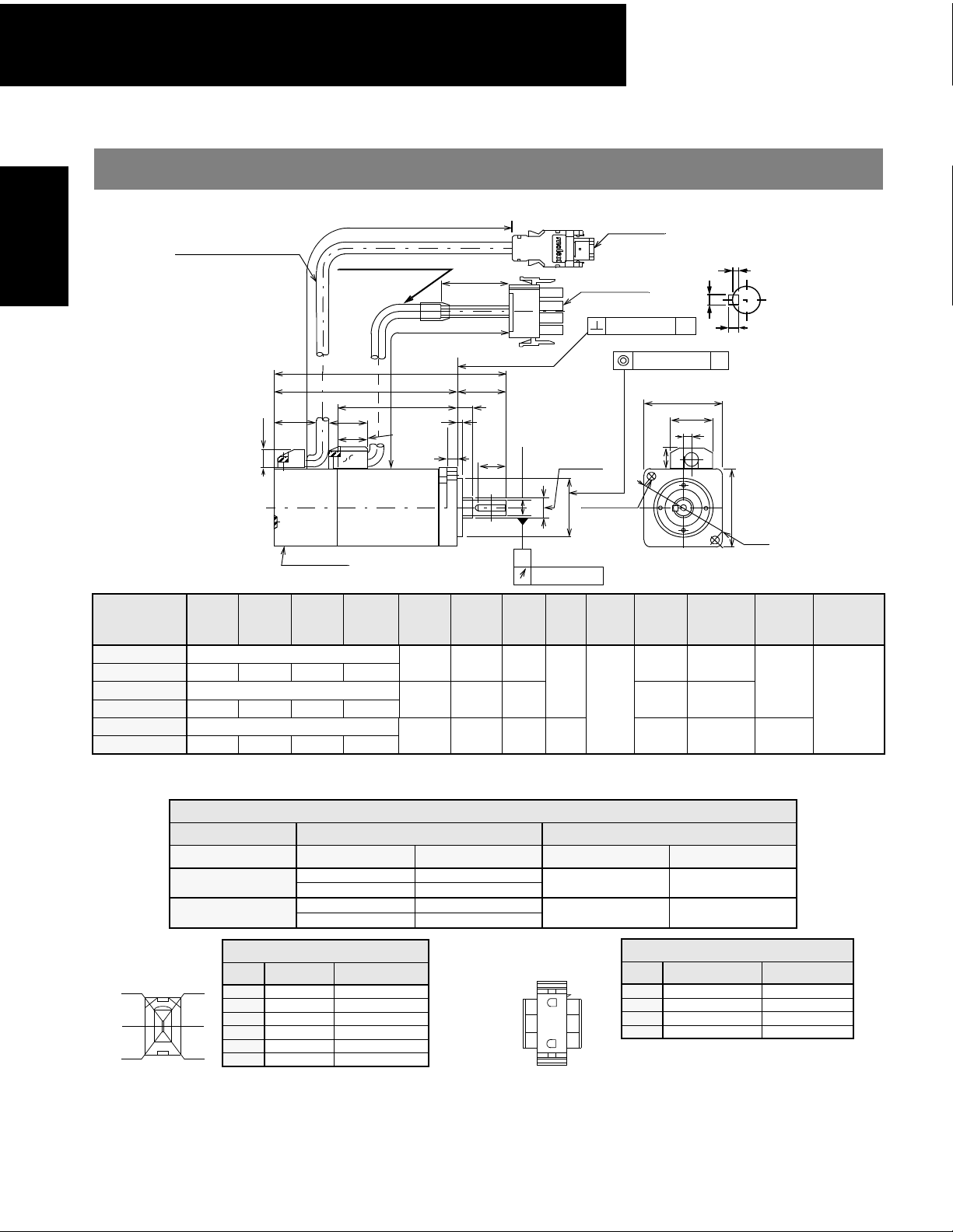
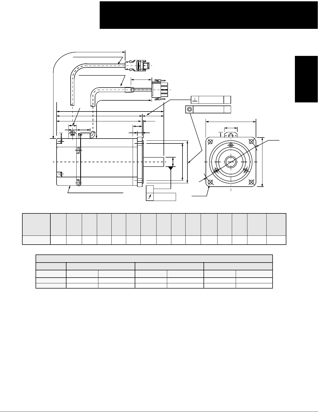
Dimensions in inches (mm)
Servomotors
SGMAH
(1) 13-Bit Incremental or 16-Bit Absolute Encoder, without Brake
• 30W (0.04hp), 50W (0.07hp), 100W (0.13hp)
ENCODER CABLE, Φ0.24 (Φ6)
UL20276
0.87 (22)
0.37 (9.5)
Serial encoder
Type
†
SGMAH-
A3F2
A3F4
A5F2
A5F4
01F2
01F4
†
Some motor dimensions vary for motors with the optional shaft seal: See p.19 for details.
Connector Specifications
Encoder Plug
5
3
1
QK U W T L LL LM ΦS* ΦLB**
Without Keyway
0.55 (14) 0.047 (1.2) 0.079 (2) 0.079 (2)
Without Keyway
0.55 (14) 0.047 (1.2) 0.079 (2) 0.079 (2)
Without Keyway
0.55 (14) 0.07 (1.8) 0.12 (3) 0.12 (3)
Dimension *ΦS **ΦLB
Unit Diameter Tolerance Diameter Tolerance
in
mm
Encoder Connection
Pin Output Wire Color
6
4
2
1PG 5V Red
2 PG 0V Black
3 Battery + Orange
4Battery − White/Orange
5 Data + Light Blue
6 Data - White/Light Blue
Note: Pins Number 3 and 4 are connectors
used for 16-bit absolute encoder option only.
Plug: 55100-0600 (Molex)
Mating connector:
Socket: 54280-0600
11.81 (300) ±1.18 (30)
Φ
MOTOR CABLE,
UL1818 or UL3535
0.79 (20)
0.28 (Φ7)
1.38 (35)
11.81 (300) ±1.18 (30)
L
0.98 (25)
LL
LM
3.72
4.02
4.7
0.30 (7.5)
(69.5)
(94.5)
0.098 (2.5)
0.60 (15.2)
0.20 (5)
(94.5)
(102)
(119.5)
2.74
3.03
(77)
3.72
Specified Tolerances
0.2362 +0.0000-0.0003
0.3150 +0.0000-0.0004
6.000 +0.000 -0.008
8.000 +0.000 -0.009
QK
Y
Y
S*
Φ
A
0.0008 (0.002)
1.44
(36.5)
1.73
(44)
2.42
(61.5)
Motor Plug
Encoder plug
55100-0600
Motor Plug
350779-1
0.0016 (0.04) A
Φ
0.0016 (Φ0.04)
Φ
0.315 (F8)
2-Φ0.17 (4.3)
LB**
Φ
0.43 (11)
Output
W (hp)
30
0.24
(6)
0.31
(8)
1.18
(30)
(0.04)
50
(0.07)
100
(0.13)
1.181 +0.0000 -0.0008
30.000 +0.000 -0.021
Pin Output Wire Color
1
d
e
4
1 Phase U Red
2 Phase V White
3 Phase W Blue
4 FG (Frame Ground) Green/Yellow
Plug 350779-1 (AMP)
Pin: 350561-3 or 350690-3 (Nos. 1 to 3)
Ground pin: 770210-1 (No 4)
Mating connector:
Cap: 350780-1
Socket: 350570-3 or 350689-3
W
Cross-section Y-Y
1.57 (40)
0.85 (21.5)
0.16 (4)
Approximate
Mass
lb (kg)
0.66
(0.3)
0.88
(0.4)
1.10
(0.5)
Motor Connection
U
T
A
1.57 (40)
Φ
1.81 (Φ46)
Allowable
Radial Load
lb (N)
15
(68)
17
(78)
Allowable
Thrust Load
lb (N)
12
(54)
12
Page 14
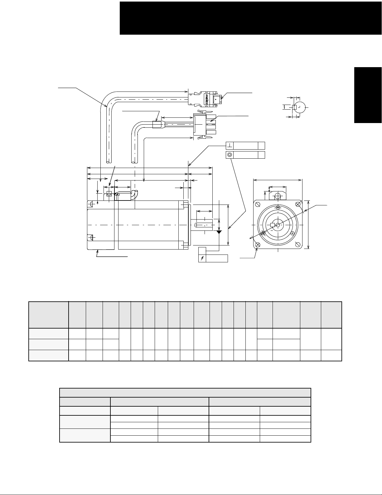
100/200V Single-phase Sigma II Servo Systems
• 200W (0.27hp), 400W (0.53hp), 750W (1.01hp)
Encoder cable, Φ0.24 (Φ6)
UL20276
1.04 (26.5)
1.04 (26.5)
0.37(9.5)
0.37(9.5)
11.85 (300) ±1.18 (30)
Motor cable
UL1818, UL3534 or UL3535
0.51 (13)
0.51 (13)
0.79 (20)
0.79 (20)
Serial encoder
Serial encoder
1.38 (35)
11.85 (300) ±1.18 (30)
L
L
LL
LL
LM
LM
Encoder plug
55100-0600
Motor plug
350779-1
0.0016 (0.04)
0.0016 (0.04)
LR
LR
0.12 (3)
LG
LG
0.12 (3)
A
QK
QK
Y
Y
Y
Y
0.0008 (0.02)
*
*
ΦS
ΦS
ΦLB**
ΦLB**
4-ΦLZ
A
A
0.43 (11)
U
W
T
Cross-section Y-Y
LC
(21.5)
0.85
SGMAH
Servomotors
ΦLA
LC
Type
SGMAH-
02F4
04AF4
08AF4
†
L LL LM LR LG LC ΦLA ΦLZ ΦS* ΦLB** QK U W T
4.98
3.8
(96.5)
4.9
5.71
(145)
2.46
(62.5)
3.56
(90.5)
4.37
(111)
1.18
(30)
1.57
(40)
0.24
(6)
0.31
(8)
2.36
(60)
3.15
(80)
2.76
(70)
3.54
(90)
0.22
(5.5)
0.28
(7)
0.55
(14)
0.63
(16)
1.97
(50)
2.76
(70)
0.79
(20)
1.18
(30)
0.12
(3)
0.12
(3)
(126.5)
6.08
(154.5)
7.28
(185)
(124.5)
*Please see the following table for dimension tolerances.
†
Some motor dimensions vary for motors with the optional shaft seal: See p.20 for details.
Specified Tolerances
Dimension *ΦS **ΦLB
Unit Diameter Tolerance Diameter Tolerance
in
mm
0.5512 +0.0000-0.0004 1.9685 +0.0000 -0.0010
0.6299 +0.0000-0.0004 2.7559 +0.0000 -0.0012
14.000 +0.000 -0.011 50.000 +0.000 -0.025
16.000 +0.000 -0.011 70.000 +0.000 -0.030
0.2
0.2
7.5
Allowable
55 (245) 17 (74)
88 (392) 33 (147)
Approximate
Output
W (hp)
200
(0.27)
0.2
(5)
(5)
400
(0.53)
0.2
(5)
750
(5)
(1.01)
Mass
lb (kg)
2.43 (1.1)
3.75 (1.7)
(3.4)
Radial
Load
lb (N)
Allowable
Thrust
Load
lb (N)
13
Page 15

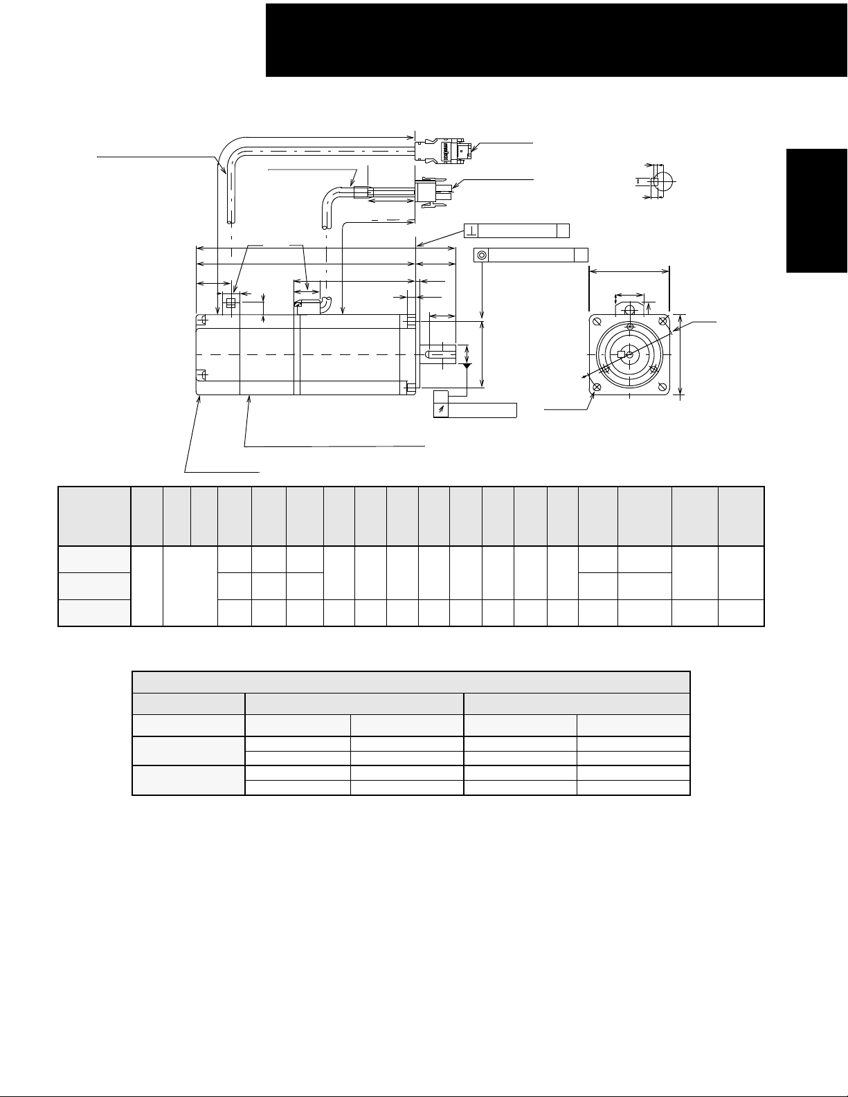
100/200V Single-phase Sigma II Servo Systems
C
ifi
(2) 13-Bit Incremental or 16-Bit Absolute Encoder, with Brake
Servomotors
SGMAH
• 30W (0.04hp), 50W (0.07hp), 100W (0.13hp)
Encoder cable, Φ0.24 (Φ6)
UL20276
0.87 (22)
0.37(9.5)
Serial encoder
Type
SGMAH-
U W T L LL LM ΦS* ΦLB** QK
†
A3F2C
A3F4C
A5F2C
0.047
(1.2)
0.079
(2)
A5F4C
01F2C
01F4C
†
Some motor dimensions vary for motors with the optional shaft seal: See p.19 for details.
0.07
(1.8)
0.12
(3)
0.12
Dimension *ΦS **ΦLB
Unit Diameter To le r an c e Diameter Tolerance
in
mm
onnector Spec
Motor Plug
cations:
3
h
5
d
1
f
11.85 (300) ±1.18 (30)
Motor cable Φ0.28 (Φ7)
UL1828 or UL3535
11.85 (300) ±1.18 (30)
0.79 (20)
0.60 (15.2)
Holding brake (de-energized operation)
DC Power supply = 24V
Brake holding torque = Motor rated torque
(3)
4.96
(126)
5.26
(133.5)
6.3
(160)
3.98
(101)
4.27
(108.5)
5.31
(135)
L
LL
LM
0.20 (5)
1.44
(36.5)
1.73
(44.0)
2.42
(61.5)
1.38 (35)
0.98 (25)
0.098 (2.5)
0.30 (25)
QK
Y
Y
0.24
(6)
0.31
(8)
Specified Tolerances
0.2362 +0.0000-0.0003
0.3150 +0.0000-0.0004
6.000 +0.000 -0.008
8.000 +0.000 -0.009
Motor Connection
1Phase U Red
2 Phase V White
3 Phase W Blue
4 FG (Frame Ground) Green/Yellow
5 Brake Terminal Red
6 Brake Terminal Black
Plug: 350715-1 (AMP)
Pin: 350561-3 or 350690-3 (except No. 4)
Ground pin: : 770210-1 (No. 4)
Mating connector:
Cap: 350781-1
Socket: 350570-3 or 350689-3
S*
Φ
A
1.18
(30)
Encoder Plug
Φ
0.315
(Φ8)
LB**
Φ
2−Φ0.17
(Φ
0.0008 (0.02)
0.55
(14)
0.55
(14)
5
3
1
Encoder plug
55100-0600
Motor plug
350779-1
0.0016 (0.04)
Φ
0.0016 (Φ0.04)
4.3)
Output
W
(hp)
A
1.57 (40)
0.85 (21.5)
0.16 (4)
0.43 (11)
Approximate
30
(0.04)
50
(0.07)
100
(0.13)
1.181 +0.0000 -0.0008
30.000 +0.000 -0.021
U
W
T
Cross-section Y - Y
A
1.57 (40)
Φ
1.81
Mass
lb (kg)
Allowable
Radial Load
1.32
(0.6)
1.54
(0.7)
1.76
(0.8)
lb (N)
(78)
Encoder Connection
6
1 PG 5V Red
2 PG 0V Black
4
3 Battery + Orange
4Battery − White/Orange
2
5 Data + Light Blue
6 Data - White/Light Blue
Note: Pins number 3 and 4 are connectors used for
16-bit absolute encoder option only.
Plug: 55100-0600 (Molex)
Mating connector:
Socket: 54280-0600
(Φ
15
(68)
18
46)
Allowable
Thrust Load
lb (N)
12
(54)
14
Page 16
100/200V Single-phase Sigma II Servo Systems
• 200W (0.27hp), 400W (0.53hp), 750W (1.01hp)
11.85 (300) ±1.18 (30)
Encoder cable, Φ0.24 (Φ6)
UL20276
1.04 (26.5)
Motor cable Φ0.28 (Φ7)
UL1828 or UL3535
11.85 (300) ±1.18 (30)
0.51 (13)
0.79 (20)
0.37 (9.5)
1.38 (35)
L
LL
LM
LR
0.12 (3)
LG
QK
Y
Encoder plug
55100-0600
Motor Plug
350715-1
0.0016 (0.04)
Φ
0.0016 (Φ0.04)
U
W
T
Cross-Section Y-Y
A
A
LC
0.85 (21.5)
0.43 (11)
ΦLA
SGMAH
Servomotors
Y
A
Holding brake (de-energized operation)
DC Power supply = 24V
Brake holding torque = Motor rated torque
0.0008 (0.02)
Serial encoder
Typ e
SGMAH-
02F4C
04AF4C
08AF4C
†
Some motor dimensions vary for motors with the optional shaft seal: See p.20 for details.
U W T L LL LM LR LG LC ΦLA ΦLZ ΦS* ΦLB** QK
†
6.54
5.35
(136)
6.46
(164)
7.46
2.46
(62.5)
3.56
(90.5)
4.37
(111)
1.18
(30)
1.57
(40)
0.24
(6)
0.31
(8)
2.36
(60)
3.15
(80)
2.76
(70)
3.54
(90)
0.22
(5.5)
0.28
0.12
(3)
0.2 (5)
(166)
7.64
(194)
9.04
(229.5)
(189.5)
Specified Tolerances
Dimension *ΦS **ΦLB
Unit Diameter Tolerance Diameter To l er a n ce
in
mm
0.5512 +0.0000-0.0004 1.9685 +0 -0.0010
0.6299 +0.0000-0.0004 2.7558 +0 -0.0012
14.000 +0.000 -0.011 50.000 +0 -0.025
16.000 +0.000 -0.011 70.00 +0 -0.03
(7)
S*
Φ
LB**
Φ
0.55
(14)
0.64
(16)
1.97
(50)
2.76
(70)
4-ΦLZ
0.79
(20)
1.18
(30)
Output
W (hp)
200
(0.27)
400
(0.53)
750
(1.01)
Approximate
Mass
lb (kg)
3.53
(1.6)
4.85
(2.2)
9.48
(4.3)
LC
Allowable
lb (N)
Radial
Load
Allowable
Thrust
55
(245)17(74)
88
(392)33(147)
Load
lb (N)
15
Page 17

100/200V Single-phase Sigma II Servo Systems
• 200W (0.27hp), 400W (0.54hp) with NEMA 23* Flange/Pilot
Servomotors
SGMAH
Encoder cable, Φ0.24 (Φ6)
UL20276
Motor cable
UL1818, UL3534 or
UL3535
0.51 (13)
1.32 (33.5)
0.37(9.5)
Serial encoder
11.85 (300) ±1.18 (30)
11.85 (300) ±1.18 (30)
0.79 (20)
LL
LM
Encoder plug
55100-0600
1.38 (35)
Motor plug
350779-1
0.0016 (0.04)
Φ0.0016 (0.04)
A
A
L
LR
LC
0.85 (21.5)
0.43 (11)
ΦLA
LC
LG
0.06
(1.6)
A
*
ΦS
0.0008 (0.02)
ΦLB**
4-ΦLZ
Type
SGMAH-
02AN21
04AN21
1.5
Output
W (hp)
200
(0.27)
400
(0.53)
L LL LM LR LG LC ΦLA ΦLZ ΦS* ΦLB**
4.67
(118.5)
5.77
(146.5)
Dimension *ΦS **ΦLB
Unit Diameter Tolerance Diameter Tolerance
mm 12.7 +0 -0.011 38.1 +0.000 -0.025
3.9
5.0
2.56
(65)
3.66
(93)
0.79
(20)
0.24
(6)
2.36
2.63
(60)
(66.7)
Specified Tolerances
0.18
(4.5)
0.50
(12.7)
(38.1)
(98.5)
(126.5)
in 0.5000 +0 -0.00043 1.5000 +0.0000 -0.00098
Approximate
Mass
lb (kg)
2.43 (1.1)
3.75 (1.7)
*For servo application torques: shaft diameter is 0.5in (12.7mm) rather than 0.25 (6.35mm), as is in typical NEMA 23.
Allowable
Radial
Load
lb (N)
55 (245) 17 (74)
Allowable
Thrust
Load
lb (N)
16
Page 18
100/200V Single-phase Sigma II Servo Systems
• 750W (1.01hp) with NEMA 34* Flange/Pilot
11.85 (300) ±1.18 (30)
1.04
(26.5)
0.37 (9.5)
Encoder cable, Φ
UL20276
Motor cable Φ0.27 (Φ7)
UL3443
0.51 (13)
0.28 (7)
0.91(23)
Φ
0.24 (Φ6)
6
1.38 (35)
11.85 (300) ±1.18 (30)
L
LL
LM
0.63 (16)
LR
0.08 (2)
LG
Encoder plug
55100-0600
Motor plug
350779-1
S*
Φ
LD***
Φ
LB**
Φ
Φ
0.0016 (Φ0.04)
0.43 (11)
A0.0016 (0.04)
A
LC
0.85 (21.5)
LC
SGMAH
Servomotors
Φ
LA
3.87
(98.4)
A
0.0008 (0.02)
0.28
(7)
0.63
(16)
2.87
(73)
Φ
LZ
4-
Approx
Output
W (hp)
2.60 (66)
750
(1.01)
Mass
lb (kg)
7.5
(3.4)
Type
SGMAH-
08AN21
13-bit serial incremental encoder
L LL LM LR LG LC ΦLA ΦLZ ΦS* ΦLB** ΦLD***
7.20
(183)
5.75
(146)
4.43
(112.5)
1.46
(37)
0.31
(8)
3.35
(85)
Specified Tolerances
Dimension *ΦS **ΦLB **Φ*LD
Unit Diameter Tolerance Diameter Tolerance Diameter Tolerance
in
mm
0.625 +0.0000-0.00043 2.874 +0.0000 -0.0012 2.598 +0.00012 -0
15.875 +0.000 -0.011 73.000 +0.000 -0.030 66.000 +0.003 -0
*For servo application torques: shaft diameter is 0.625in (15.875mm) rather than 0.375 (9.525mm), as is in typical NEMA 34.
Allowable
Radial
Load
lb (N)
88 (392) 33 (147)
Allowable
Thrust
Load
lb (N)
17
Page 19
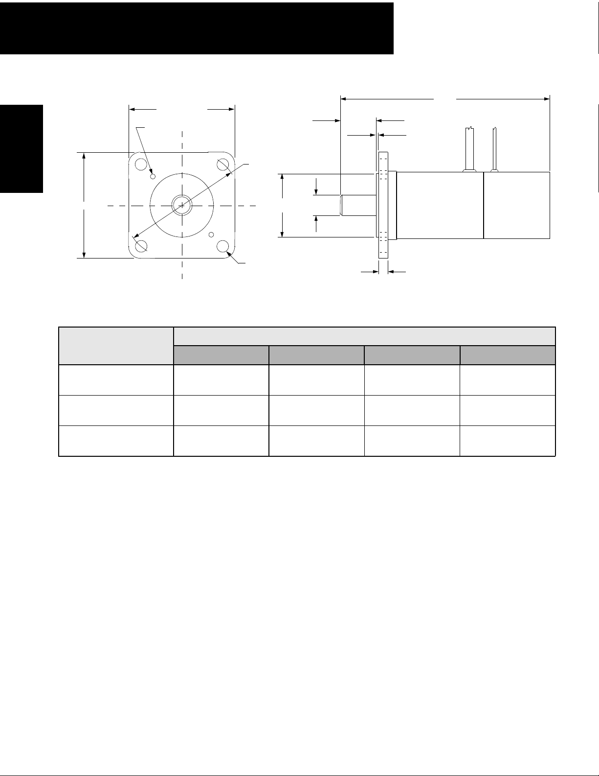
100/200V Single-phase Sigma II Servo Systems
Servomotors
SGMAH
2.27 (57.7)
8-32 UNC - 2 places
0.73 (18.6)
∅ LA
L
0.06 (1.5)
2.27 (57.7)
∅ LB ∅ S
∅ 0.206 (5.2)
4 places
Motor type *Dimensions - Inch (mm)
L ∅ S ∅ LB ∅LA
SGMAH-A3
w/NEMA 23 Adaptor
SGMAH-A5
w/NEMA 23 Adaptor
SGMAH-01
w/NEMA 23 Adaptor
3.72 (94.5) 0.2362
(6.0 +.000 / -.006)
4.02 (102) 0.2362
(6.0 +.000 / -.006)
4.70 (119.5) 0.3150
(8.0 +.000 / -.009)
+.000 / -.0003
+.000 / -.0003
+.000 / -.0004
*Dimensions include a field installed SGM-N23 adapter flange on the listed motor.
0.19 (4.8)
1.500
+.002 / -.002
(38.1 +.05 / -.05)
1.500
+.002 / -.002
(38.1 +.05 / -.05)
1.500
+.002 / -.002
(38.1 +.05 / -.05)
2.625 (66.7)
2.625 (66.7)
2.625 (66.7)
18
Page 20
100/200V Single-phase Sigma II Servo Systems
•
Dimension Modifications for Motors with Optional Shaft Seal
• 30W (0.04hp), 50W (0.07hp), 100W (0.13hp)
LR
LE
LD
QK
S
Shaft seal
Φ
ΦLP
ΦLB
Type SGMAH- QK ΦLB* ΦS* LE LR LD ΦLP
A3
A5
01 0.315 (8)
0.55 (14) 1.18 (30)
0.236 (6)
0.10 (2.5) 0.98 (25) 0.30 (7.5) 1.14 (28)
SGMAH
Servomotors
*Tolerances for diameters LB and S are the same as those for motors without shaft seals.
19
Page 21
100/200V Single-phase Sigma II Servo Systems
• 200W (0.27hp), 400W (0.53hp), 750W (1.01hp)
LR
Servomotors
SGMAH
LE
LD
QK
S
Φ
ΦLP
ΦLB
Shaft seal
Type SGMAH- QK ΦLB* ΦS* LE LR LD ΦLP
02
04
08 0.98 (25) 2.76 (70) 0.63 (16) 1.57 (40) 0.43 (11) 2.60 (66)
*Tolerances for diameters LB and S are the same as those for motors without shaft seals.
0.55 (14) 1.97 (50) 0.55 (14)
0.12 (3)
1.18 (30) 0.39 (10) 1.89 (48)
Torque Reduction Factor for SGMAH motors equipped with a shaft seal:
Servo Motor Model A3 A5 01 02 04 08
Torque Reduction
Factor
For example: The SGMAH-A3 continuous and peak torque rating should be reduced to 70%
of the listed catalog specification.
70% 80% 90% 90% 95% 95%
20
To specify a motor with a shaft seal, refer to the motor part number explanation on the
following page.
Page 22
100/200V Single-phase Sigma II Servo Systems
Selecting Your SGMAH Sigma II Servo System
First, select the Sigma II servomotor suited for your application using SigmaSize: the Yaskawa
servomotor sizing software, available at no charge. (Request SigmaSize software via e-mail, at:
literature@yaskawa.com).
Use the diagram below to locate and identify the components of your system. Each item is lettercoded and cross-referenced in the option tables on the following pages.
System Configuration
SGMAH
Servomotors
Digital Operator (E)
3CN
Peripheral
Signal
Cable (E)
1CN
I/O Signal
Connector
(D)
Regenerative Unit (E)
SGDH Servo
Amplifier
(B)
Model Number Designation
SGMAH - 01 A A F 4 1
Sigma II Servomotor Type
Rated Output
A3: 30W (0.04hp)
A5: 50W (0.07hp)
01: 100W (0.13hp)
02: 200W (0.25hp)
04: 400W (0.5hp)
08: 750W (1hp)
Power Supply
A: 200V
B: 100V
5CN
For Monitor (D)
Connector
Encoder (D)
Encoder side
Connector (D)
2CN
Encoder Cable (C)
Motor Cable (C)
Optional Holding Brake
Shaft Keyway
SGMAH
Servomotor
(A)
Shaft Seal
Motor side
Connector (D)
Specify a technical manual, if it is needed, on your
servo system purchase order:
Sigma II Series Servo System User’s Manual: YEA-SIA-S800-32.2
(Manual is provided at no charge with a purchase order,
but it must be requested).
Accessories
1: Standard
C: Standard with 24V
S: Standard with Shaft Seal*
E: Standard with Brake & Shaft Seal*
Shaft Specifications
4: Straight Shaft with Keyway*
2: Straight Shaft without Keyway
Revision Level
F: Standard
N: NEMA flange (200W, 400W & 800W
only without holding brake)
Encoder Specifications
A: 13-bit (2048 x 4) Incremental Encoder
1: 16-bit (16384 x 4) Absolute Encoder
Brake*
DC
* Keyways, shaft seals, and holding brakes not available on motors with NEMA flanges (revision level = N).
21
Page 23
100/200V Single-phase Sigma II Servo Systems
Servomotor & Amplifier Selection
Servomotors
SGMAH
Use the table below to select the recommended SGMAH Sigma II servomotor and amplifier.
(Refer to the motor model # designation on the previous page specifying the available modification to motor
construction/features.)
Motors Used with 13-bit Incremental Encoders (5000rpm Maximum) Amplifier
Amplifier MODEL NUMBER
(B)*
Single-Phase
SGDH
A3AE –
A5AE –
01AE
01AE –
02AE –
04AE –
08AE-S 08AE
01AE –
A3BE –
A5BE –
01BE –
01BE –
02BE –
04FE –
01BE –
3-Phase
SGDH-
–
–
Description
200V,
Single-Phase
Straight Shaft
without Keyway
200V,
Single-Phase,
Straight Shaft with
Keyway
200V,
Single-Phase,
Straight Shaft
without Keyway
NEMA flange
100V,
Single-Phase,
Straight Shaft
without Keyway
100V,
Single-Phase,
Straight Shaft
with Keyway
100V,
Single-Phase,
Straight Shaft
without Keyway
NEMA flange
Notes: 24V
brakes for SGMAH Sigma II servomotors are standard. Contact a local source for 24VDC power supplies.
DC
Motor power and encoder cables are factory pre-wired with approximately 13” lead length with amplifier mating connectors.
Use the tables on the following pages to specify mating connectors or pre-wired cables available in various lengths.
For technical information, request Yaskawa manual number YEA-SIA-S800-32.2.
* For more detailed SGDH amplifier specifications and dimensions, refer to pages 95 to 110.
** NEMA 23 adapter flange (see "Peripheral Device Selection")
*** NEMA 23 flange and pilot (see "Dimensions in inches (mm)")
**** NEMA 34 flange and pilot (see "Dimensions in inches (mm)")
Peak
Torque
(oz • in)
40.5 13.5
67.7 22.6
135 45.1
270 90.1
542 181
1010 338
135 45.1
270 90.1 1.50
542 181 2.45
1010 338 9.52
40.5 13.5
67.7 22.6
135 45.1
270 90.1
542 181
135 45.1
270 90.1 1.50
542 181 2.45 SGMAH-04AAN21*** 04FE –
Rated
Torque
(oz • in)
Motor Inertia
(oz • in • s
0.235
0.355
0.312
0.432
0.515
0.635
0.515
0.635
1.50
2.321
2.45
3.271
9.52
11.5
0.515
0.635
0.235
0.355
0.312
0.432
0.515
0.635
0.515
0.635
1.50
2.321
2.45
3.271
0.515
0.635
2
×10-3)
Motor
MODEL NUMBER (A)
SGMAH-A3AAF21
SGMAH-A3AAF2C
SGMAH-A5AAF21
SGMAH-A5AAF2C
SGMAH-01AAF21
SGMAH-01AAF2C
SGMAH-01AAF41
SGMAH-01AAF4C
SGMAH-02AAF41
SGMAH-02AAF4C
SGMAH-04AAF41
SGMAH-04AAF4C
SGMAH-08AAF41
SGMAH-08AAF4C
SGMAH-01AAF21**
SGMAH-01AAF2C**
SGMAH-02AAN21*** 02AE
SGMAH-04AAN21*** 04AE
SGMAH-08AAN21**** 08AE-S 08AE
SGMAH-A3BAF21
SGMAH-A3BAF2C
SGMAH-A5BAF21
SGMAH-A5BAF2C
SGMAH-01BAF21
SGMAH-01BAF2C
SGMAH-01BAF41
SGMAH-01BAF4C
SGMAH-02BAF41
SGMAH-02BAF4C
SGMAH-04AAF41
SGMAH-04AAF4C
SGMAH-01BAF21**
SGMAH-01BAF2C**
SGMAH-02BAN21*** 02BE
Motor &
Amplifier
Item Class
Stock
22
Page 24
100/200V Single-phase Sigma II Servo Systems
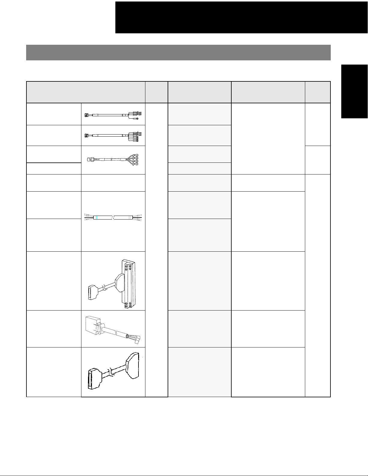
Pre-wired Cable Selection
Use the table below to select pre-wired cables for your SGMAH Sigma II servomotor.
Cable Description (C)
Power Cable
without Brake
Power Cable with
Brake
Shielded Power
Cable without
Brake***
Shielded Power
Cable with Brake***
Encoder Cable
(incremental and
absolute)
Encoder Cable
(for applications
up to 20m)
Only for Solder
Connections
Encoder Cable
(for applications
from >20 to <50m
maximum)
Only for Solder
Connections
—
Motor
Size
(kW)
All
Part Number* Comments
JZSP-CMM00-(A)
JZSP-CMM10-(A)
BAHCE-(A)
BAHBCE-(A)
JZSP-CMP00-(A) —
FR-RMCT-SB
UL20276-SB
These cables are available
in five lengths. Use two digits in the part number’s last
place:
03: 3m
05: 5m
10: 10m (standard)
15: 15m
20: 20m
These cables are available
in any length.
For example, to order one
FR-RMCT-SB cable, 16m
long, specify:
quantity: 16
part no.: FR-RMCT-SB
Item
Class
SGMAH
Servomotors
Stock**
Limited
Stock
Input/Output 1CN
Cable & Transition
Terminal Block
Input/Output 1CN
Cable with Pigtail
Leads
Input/Output 1CN
Cable Cable with
Female
D-Sub output Connector****
JUSP-TA50P
JZSP-CKI01-(A)
JZSP-CKI0D-
35mm DIN rail mountable;
the cable length is 0.5
meters.
Use the following key to
specify required cable length
(last digit of part number):
1: 1m (standard)
2: 2m
3: 3m
Use the following key to
specify required cable length
(last two digits of the part
number):
D50: 0.5m
01: 1m (standard)
02: 2m
03: 3m
* “(A)” at the end of the cable part number is the revision level. Revision level may be changed prior to this catalog reprinting.
** Standard cable lengths are Stock items; non-standard cable lengths are Limited Stock items.
*** Use these power cables where it is important to meet CE (EMC) requirements.
**** 50 Pin Female D-Sub output connector mates to customer supplied third party terminal block. (e.g., Wago #289-449,
Weidmuller #919658, Phoenix #2283647, Amphenol/Sine #20-51039, and many others).
Stock
23
Page 25
100/200V Single-phase Sigma II Servo Systems
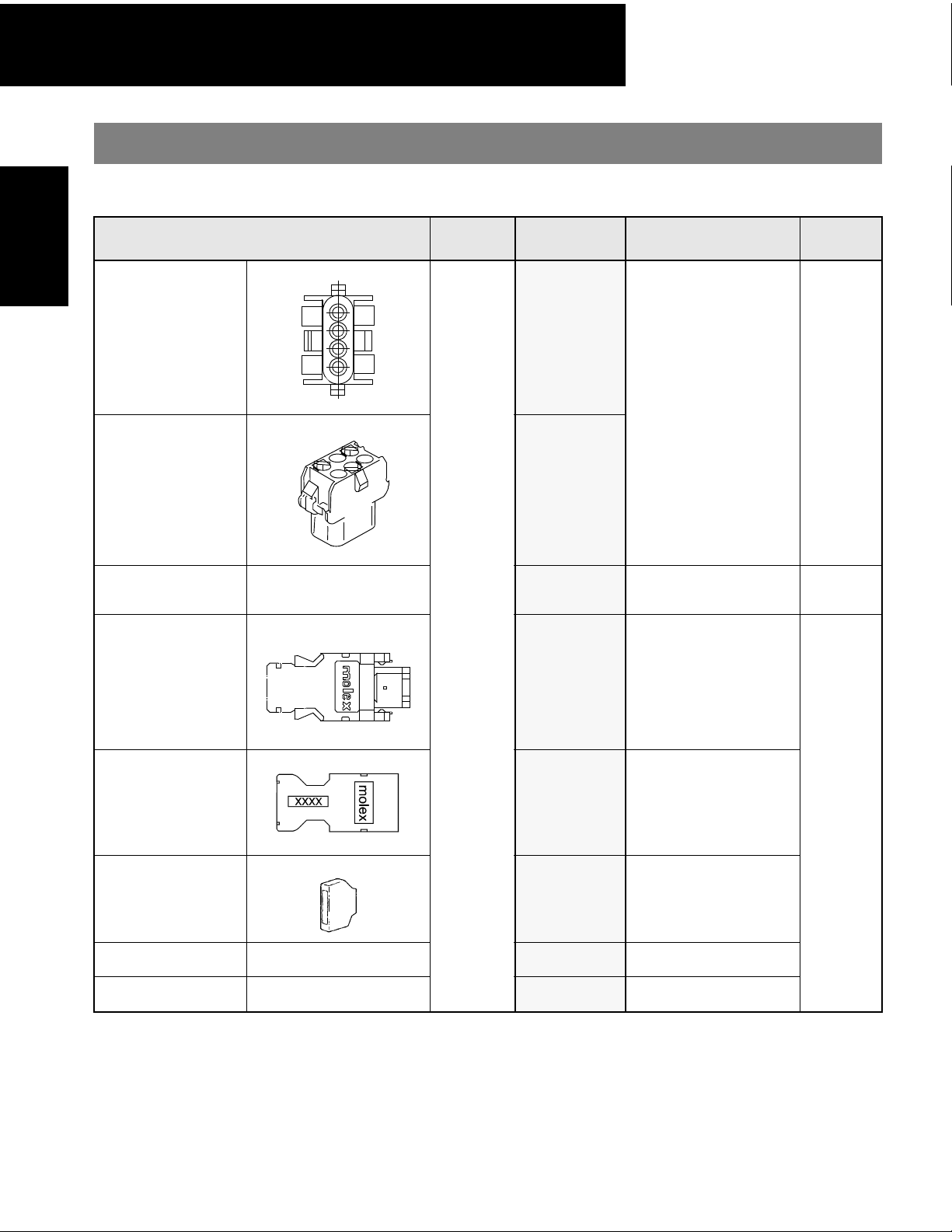
Connector Selection
Servomotors
SGMAH
Use the table below to select mating connectors or kits for your SGMAH Sigma II servomotor.
Connector Description (D)
Motor Power
Mating Connector
(without Brake)
Motor Power
Mating Connector
(with Brake)
Amp Crimp Tool —
Motor Size
(kW)
Part Number Comments
JZSP-CMM9-1
These connector kits
include pin and socket.
Requires use of Amp
Crimp Tool (90548-1).
(See below).
JZSP-CMM9-2
90548-1
Crimp tool for Motor
Power Connector
(JZSP-CMM9-)
Item
Class
Stock
Limited
Stock
2CN Amplifier
Mating Connector
Motor Encoder
Mating Connector
1CN Mating
Connector
3CN Peripheral
Mating Connector
5CN Analog Monitor
Connector
—
—
All
JZSP-CMP9-1 —
JZSP-CMP9-2 —
JZSP-CKI9
YSC-1 —
DE9404559 —
for SGDH I/O
50-pin
Stock
24
Page 26
100/200V Single-phase Sigma II Servo Systems
Peripheral Device Selection
Use the table below to select peripheral devices for your SGMAH Sigma II servomotor.
Component Description (E) Part Number Comments Item Class
SGMAH
Servomotors
Hand-held Digital
Operator Panel
Absolute Encoder Battery
Software Interface Cable —
SigmaWin+ Software
For 200V: SGDH-A3AE
DC Reactor
(for suppressing harmonics
in the power supply)
Individual External Regenerative Unit
NEMA Flange Adapter —
For 100V: SGDH-A3BE
50 Ω, 70W for A3, A5, 01, 02,
04, AND 08 AMPS
SGDH-A5AE
SGDH-01AE
SGDH-02AE
SGDH-04AE
SGDH-08AE
SGDH-08AE-S
SGDH-A5BE
SGDH-01BE
SGDH-02BE
JUSP-OP02A-1
and
JZSP-CMS00-1
JZSP-BA01 3.6V, 1000mAh (lithium battery)
YS-12
JZSP-WP0001
—
—
X5071
X5070
X5069
X5061
X5079
—
—
X5063
X5062
RH120-50ohmJ
SGM-N23
Portable unit with 1m adapter cable
for Sigma II
Pre-wired 2.0m cable with
9-pin connector
Minimum Recommended System
Requirements Pentuim 200 MHz,
64MB RAM, 200MB hard drive,
CDROM Drive, RS-232 or RS-422
port, Screen rsolution 800x600 w/
256 colors, and Windows
95,98,NT4.0,2000,ME. (Windows
XP planned)
—
—
This is a general purpose
regenerative unit.*
Caution: Proper set-up is necessary to avoid equipment damage.
For 30, 50, and 100W SGMAH
motors only. Complies to NEMA 23
mounting standard.
* Refer to the SGDH servo amplifier section of this catalog for additional specifications, and the Sigma II Series Servo System
User’s Manual (YEA-SIA-S800-32.2) for proper resistor sizing guidelines.
Stock
Limited
Stock
Stock
25
Page 27

100/200V Single-phase Sigma II Servo Systems
NOTES:
Servomotors
SGMAH
26
Page 28
100/200V Single-phase Sigma II Servo Systems
Flat Series
SGMPH Servomotors - With Incremental / Absolute Encoder
Rated Output: 100W, 200W, 400W,
750W, 1500W
For Additional Information Page(s)
SGMPH Ratings & Specifications
SGMPH Speed/Torque Curves
SGMPH Dimensions
SGMPH Selection/Ordering Information
SGDH Ratings & Specifications
SGDH Dimensions
30
31
32 - 40
41 - 45
99 - 100
101 - 112
SGMPH
Servomotors
Design Features
1. Compact
z The length is about 1/2 of conventional motors
z Enhanced withstand load since motor output shaft bearing size is upgraded
z Up to 5000rpm maximum speed
2. Enhanced Environmental Resistance
z Water resistance (not including the shaft), IP67 standard
z Optional shaft seals available
z Reinforced lead-out cable access
3. Encoders (reduced wiring serial encoder)
z 13-bit (2,048ppr x 4) incremental encoder (standard)
z 16-bit (16,384ppr x 4) absolute encoder (option)
4. Application Emphasis
z Chip mounters
z PCB drilling machines
z Robots
z Conveyor
z Packaging
5. Certified International Standards
z UL, cUL recognized, (File #: E165827), CE compliance
27
Page 29
100/200V Single-phase Sigma II Servo Systems
Servomotor Ratings and Specifications
Time Rating: Continuous
Insulation: Class B
Vibration: 15
Withstand Voltage: 1500V
Insulation Resistance: 500V
Servomotors
SGMPH
μ
m or less
ac
DC
10MΩ or more
M O T O R S :
SGMPH-
Applied
Voltage
01A 100 (0.13) 45.1 0.318 135 0.96 0.89 2.8 64800 20.4
02A 200 (0.27) 90.1 0.637 270 1.91 2.0 6.0 33000 21.0
ac
04A 400 (0.54) 180 1.27 542 3.82 2.6 8.0 38500 49.0
200V
08A 750 (1.01) 338 2.39 1010 7.1 4.1 13.9 11400 27.0
15A 1500 (2.01) 676 4.77 2027 14.3 7.5 23.0 11900 56.7
01B 100 (0.13) 45.1 0.318 135 0.96 2.2 7.1 64800 20.4
ac
02B 200 (0.27) 90.1 0.637 270 1.91 2.7 8.4 33000 21.0
100V
04A** 400 (0.54) 180 1.27 542 3.82 2.6 8.0 38500 49.0
Rated
Output
W (hp) oz • in N • m oz • in N • m
Enclosure: Totally-enclosed, self-cooled
Ambient Temperature: 0 to 40ºC
Ambient Humidity: 20 to 80%
(non-condensing)
Rated Rotation Speed: 3000rpm
Maximum Rotation Speed:5000rpm
Rated
Torque
Instantaneous Peak
Torque
Continuous
Rated
Current
A
rms
Excitation: Permanent magnet
Drive Method: Direct drive
Mounting: Flange-mounted
Applicable Encoder:
13-bit Incremental and
16-bit Absolute encoder
Maximum
*
Peak
Current
A
rms
*
Rated
Angular
Acceleration
2
rad/s
Rated
Power Rate
kW/s
* Values are calculated when the servomotor is combined with an SGDH servo amplifier.
** When combined with an SGDH-04FE
Moment of Inertia Holding Brake (at 20°C)
Coil
Resistance
× 10
Capacity
-4
W Ω A
MOTORS
SGMPH-
System Voltage
01A 0.695 0.0491 1.106 0.0781 6 96 0.25 1.20
02A 2.73 0.193 4.274 0.302 5 115 0.21 3.69
ac
04A 4.69 0.331 6.234 0.44 7.6 76 0.32 3.82
200V
08A 29.7 2.10 42.09 2.975 7.5 77 0.31 13.4
15A 56.9 4.02 69.29 4.895 10 58 0.42 24.1
01B 0.695 0.0491 1.106 0.0781 6 96 0.25 1.20
ac
02B 2.73 0.193 4.274 0.302 5 115 0.21 3.69
100V
04A 4.69 0.331 6.234 0.44 7.6 76 0.32 3.82
Motor without Brake Motor with Brake
2
oz • in • s
-3
× 10
KG • m2 × 10-4oz • in • s2 × 10-3KG • m
2
Rated
Current
* Allowable load inertia (JL) shows the range requiring no exterior regenerative unit. When these values are exceeded, applica-
tion may be restricted or a regenerative unit may be required. Values are calculated when the servomotor is combined with an
SGDH servo amplifier.
MOTORS
SGMPH-
01 100 69.5 5.0
02 200 139 10
04A 400 279 20
08A 750 514 37
15A 1500 1015 73
Servomotor
Capacity
W
Holding Brake
Holding Torque
oz-in
KG · cm
Allowable
Load
Inertia *
KG • m
2
× 10
-4
28
Page 30
100/200V Single-phase Sigma II Servo Systems
㩷
㪆
㪆
Speed / Torque Curves
200V
SGMPH-01A SGMPH-02A SGMPH-04A
㪌㪇㪇㪇
㪋㪇㪇㪇
㪊㪇㪇㪇
㩷㩷㩷㩷㩷㩷㪙
㪘
㪉㪇㪇㪇
㪪㪧㪜㪜㪛㩷㩿㫉㫇㫄㪀
㪈㪇㪇㪇
㪇
㪇㩷㩷㩷㪇㪅㪉㪌㩷㩷㩷㪇㪅㪌㩷㩷㩷㪇㪅㪎㪌㩷㩷㪈㪅㪇
㪫㪦㪩㪨㪬㪜㩷㩿㪥㩷㩷㫄㪀
㪇㩷㩷㩷㩷㩷㩷㩷㩷㩷㩷㩷㩷㩷㪌㪇㩷㩷㩷㩷㩷㩷㩷㩷㩷㩷㪈㪇㪇㩷㩷㩷㩷㩷㩷㩷㩷㩷㪈㪌㪇
㪫㪦㪩㪨㪬㪜㩷㩿㫆㫑㪆㫀㫅㪀
SGMPH-08A SGMPH15A
㪌㪇㪇㪇
㪋㪇㪇㪇
㪊㪇㪇㪇
㪉㪇㪇㪇
㪪㪧㪜㪜㪛㩷㩿㫉㫇㫄㪀
㪈㪇㪇㪇
㩷㩷㩷㩷㩷㪙㪘
㪇
㪇㩷㩷㩷㩷㪇㪅㪌㩷㩷㩷㩷㩷㪈㩷㩷㩷㩷㩷㪈㪅㪌㩷㩷㩷㩷㩷㪉
㪇㩷㩷㩷㩷㩷㩷㩷㩷㩷㩷㩷㩷㩷㪈㪇㪇㩷㩷㩷㩷㩷㩷㩷㩷㩷㪉㪇㪇㩷㩷㩷㩷㩷㩷㪊㪇㪇
㪫㪦㪩㪨㪬㪜㩷㩿㫆㫑㪆㫀㫅㪀
㪫㪦㪩㪨㪬㪜㩷㩿㪥㩷 㩷㫄㪀
㪌㪇㪇㪇
㪋㪇㪇㪇
㪊㪇㪇㪇
㩷㩷㩷㩷㩷㩷㪙
㪘
㪉㪇㪇㪇
㪪㪧㪜㪜㪛㩷㩿㫉㫇㫄㪀
㪈㪇㪇㪇
㪇
㪇㩷㩷㩷㩷㩷㪈㩷㩷㩷㩷㩷㩷㪉㩷㩷㩷㩷㩷㩷㪊㩷㩷㩷㩷㩷㩷㩷㪋
㪫㪦㪩㪨㪬㪜㩷㩿㪥㩷㩷㫄㪀
㩷㩷㪇㩷㩷㩷㩷㩷㩷㩷㩷㩷㩷㩷㪉㪇㪇㩷㩷㩷㩷㩷㩷㩷㩷㩷㩷㪋㪇㪇㩷㩷㩷㩷㩷㩷㪍㪇㪇
㪫㪦㪩㪨㪬㪜㩷㩿㫆㫑㪆㫀㫅㪀
100V
㪪㪧㪜㪜㪛㩷㩿㫉㫇㫄㪀
㪌㪇㪇㪇
㪋㪇㪇㪇
㪊㪇㪇㪇
㪉㪇㪇㪇
㪪㪧㪜㪜㪛㩷㩿㫉㫇㫄㪀
㪈㪇㪇㪇
SGMPH-01B SGMPH-02B
㪌㪇㪇㪇
㪋㪇㪇㪇
㪊㪇㪇㪇
㪉㪇㪇㪇
㪈㪇㪇㪇
㩷㩷㩷㩷㩷㩷㪙㪘
㪇
㪇㩷㩷㩷㪇㪅㪉㪌㩷㩷㩷㪇㪅㪌㩷㩷㪇㪅㪎㪌㩷㩷㩷㪈㪅㪇
㪫㪦㪩㪨㪬㪜㩷㩿㪥㩷㩷㫄㪀
㪇㩷㩷㩷㩷㩷㩷㩷㩷㩷㩷㩷㩷㩷㪌㪇㩷㩷㩷㩷㩷㩷㩷㩷㩷㩷㪈㪇㪇㩷㩷㩷㩷㩷㩷㩷㩷㩷㪈㪌㪇
㪫㪦㪩㪨㪬㪜㩷㩿㫆㫑㪆㫀㫅㪀
㩷㩷㩷㩷㩷㩷㩷㪙
㪘
㪇
㪇㩷㩷㩷㩷㩷㪉㩷㩷㩷㩷㩷㩷㪋㩷㩷㩷㩷㩷㩷㪍㩷㩷㩷㩷㩷㩷㪏
㪫㪦㪩㪨㪬㪜㩷㩿㪥㩷㩷㫄㪀
㪇㩷㩷㩷㩷㩷㩷㩷㩷㩷㩷㪋㪇㪇㩷㩷㩷㩷㩷㩷㩷㩷㩷㪏㪇㪇㩷㩷㩷㩷㩷㩷㩷㪈㪉㪇㪇
㪫㪦㪩㪨㪬㪜㩷㩿㫆㫑㪆
㫀㫅㪀
㪌㪇㪇㪇
㪋㪇㪇㪇
㪊㪇㪇㪇
㪉㪇㪇㪇
㪪㪧㪜㪜㪛㩷㩿㫉㫇㫄㪀
㪈㪇㪇㪇
㪌㪇㪇㪇
㪋㪇㪇㪇
㪊㪇㪇㪇
㪉㪇㪇㪇
㪪㪧㪜㪜㪛㩷㩿㫉㫇㫄㪀
㪈㪇㪇㪇
㪇
㪇㩷㩷㩷㩷㩷㪋㩷㩷㩷㩷㩷㩷㪏㩷㩷㩷㩷㩷㪈㪉㩷㩷㩷㩷㩷㪈㪍
㩷㪇㩷㩷㩷㩷㩷㩷㩷㩷㩷㩷㩷㩷㪏㪇㪇㩷㩷㩷㩷㩷㩷㩷㩷㪈㪍㪇㪇㩷㩷㩷㩷㩷㪉㪋㪇㪇
㩷㩷㩷㩷㩷㩷㪙㪘
㪇
㪇㩷㩷㩷㩷㪇㪅㪌㩷㩷㩷㩷㩷㪈㩷㩷㩷㩷㩷㪈㪅㪌㩷㩷㩷㩷㩷㪉
㪫㪦㪩㪨㪬㪜㩷㩿㪥㩷㩷㫄㪀
㪇㩷㩷㩷㩷㩷㩷㩷㩷㩷㩷㩷㩷㪈㪇㪇㩷㩷㩷㩷㩷㩷㩷㩷㩷㩷㪉㪇㪇㩷㩷㩷㩷㩷㩷㩷㩷㩷㪊㪇㪇
㪫㪦㪩㪨㪬㪜㩷㩿㫆㫑㪆
㫀㫅㪀
㩷㩷㩷㩷㩷㩷㩷㪙㪘
㪫㪦㪩㪨㪬㪜㩷㩿㪥㩷㩷
㪫㪦㪩㪨㪬㪜㩷㩿㫆㫑㪆㫀㫅㪀
㫄㪀
SGMPH-04A*
5000
4000
3000
3000
A
2000
1000
0
0
㩷㩷㪇㩷㩷㩷㩷㩷㩷㩷㩷㩷㩷㩷㪉㪇㪇㩷㩷㩷㩷㩷㩷㩷㩷㩷㩷㪋㪇㪇㩷㩷㩷㩷㩷㩷㪍㪇㪇
B
234
1
㪫㪦㪩㪨㪬㪜㩷㩿㪥㩷㩷㫄㪀
㪫㪦㪩㪨㪬㪜㩷㩿㫆㫑㪆㫀㫅㪀
SGMPH
Servomotors
A : CONTINUOUS DUTY ZONE
B : INTERMITTENT DUTY ZONE
*When combined with SGDH-04FE amplifier.
29
Page 31

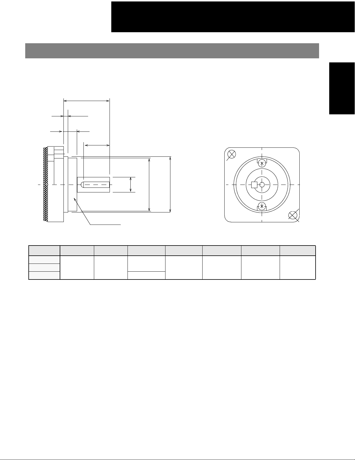
100/200V Single-phase Sigma II Servo Systems
Dimensions in inches (mm)
(1) 13-Bit Incremental or 16-Bit Absolute Encoder, w/o Brake
Note: 1. The keyway complies with JIS B1301-1976 (precision). A straight key is supplied.
2. Conforms to the IP67 enclosure, excluding the shaft (optional shaft seal available).
3. The quoted allowable radial load is the value at a position 5mm (0.2in) from the shaft end.
• 100W (0.13hp)
Encoder cable
UL20276
Φ
0.24 (6)
11.81 (300) ±1.18 (30)
Encoder plug
SRUC 17GMRCN087
U
Servomotors
SGMPH
Type SGMPH- L LL LM LR LG LC ΦLA ΦLZ ΦS* ΦLB**
01E41D
01E41D
Note: The quoted allowable radial load is the value at a position 0.79in ( 20mm.) from the mounting surface.
†
Motor Plug
Motor cable
SRUC 06JMSCN236
Hexagonal nut
11.81 (300) ±1.18 (30)
L
LR
LL
LM
0.42 (10.5)
0.12 (3)
0.0016 (0.04)
Φ
0.0016 (Φ0.04)
Opposite Side width: 0.55 (14)
A
LG
Φ
QK
0.35 (9.0)
0.55
0.51
(14)
(13)
Serial encoder
Y
ΦLB**
Y
ΦS*
A
0.0008 (0.002)
4 - Φ
(absolute or incremental)
3.43
(87)
2.44
(62)
1.67
(42.5)
0.98
(25)
0.24
(6)
2.36
(60)
2.76
(70)
0.21
(5.3)
0.315
(8)
QK U W T
1.97
0.55
(50)
(14)
0.071
(1.8)
Key
0.12
(3)
0.12
(3)
Output
W (hp)
100
(0.13)
Some motor dimensions vary for motors with the optional shaft seal: See p.38 for details.
Specified Tolerances
Dimension
Unit Diameter Tolerance Diameter Tolerance
in 0.3150 +0.0000-0.0004 1.9685 +0.0000 -0.0010
mm 8.000 +0.000 -0.009 50.000 +0.000 -0.025
Encoder Plug Motor Plug
1
11
2
10
12
13
16
3
4
SRUC 17GMRCN087
(Interconnectron)
9
17
15
14
8
5
7
6
Incremental Terminal Specifications
Pin No. Description Color
1* Battery - —
2* Battery * (3.6V) —
3 Data + Blue
4Data− Blue/White
5 - 7, 10 - 17 Free —
8 +5V (Power Supply) Red
9 0V (Power Supply) Black
Connector Case FG (Frame Ground) Shield wire
*Note: Incremental Terminal pins number 1 and 2 are connectors
used for 16-bit absolute encoder option only.
Mating Connector: SPNA17HFRON16900E3
*ΦS **ΦLB
1
2
3
SRUC 06JMSCN236
(Interconnectron)
(Interconnectron)
6
4
W
T
Cross-section Y-Y
A
LC
0.83 (21)
LA
LZ
Torque
(N•m)
(0.318)
in•lb
2.81
Time
Rating
Continu-
ous
Rated
Speed
(rpm)
3000
Motor Wiring Specifications
Pin
Number
5
1 Phase U Red
2Phase VWhite
3 Phase W Blue
6 FG (Frame Ground) Green/Yellow
Mating Connector: SPNA06KFSDN169
Description Color
0.71 (18)
LC
Approx
Mass
lb (kg)
1.54
(0.7)
(Interconnectron)
Allowable
Radial
Load
lb (N)
17.5
(78)
Allowable
Thrust
Load
lb (N)
11.0
(49)
30
Page 32

100/200V Single-phase Sigma II Servo Systems
• 200W (0.27hp), 400W (0.53hp)
Encoder cable
Φ
UL20276
0.24 (6)
11.81 (300) ±1.18 (30)
Motor cable
Encoder plug
SRUC 17GMRCN087
Motor Plug
SRUC 06JMSCN236
U
W
T
Cross-section Y-Y
11.81 (300) ±1.18 (30)
L
0.28 (7)
LL
LM
0.33 (8.5)
LG
LR
0.12 (3)
0.0016 (0.04)
Φ
0.0016 (Φ0.04)
A
A
0.35
(9.0)
0.51
(13)
0.55
(14)
Serial encoder
QK
Y
Y
S*
Φ
A
0.0008 (0.02)
LB**
Φ
(absolute or incremental)
Key
Type SGM PH- L LL LM LR LG LC ΦLA ΦLZ ΦS* ΦLB**
3.82
2.64
02E41D
04E41D
Note: The quoted allowable radial load is the value at a position 0.98in (25mm) from the mounting surface.
†
Some motor dimensions vary for motors with the optional shaft seal: See p.38 for details.
(97)
4.61
(117)
(67)
3.46
(87)
1.89
(48.1)
2.68
(68.1)
1.18
(30)
0.31
(8)
3.15
(80)
3.54
(90)
0.28
(7)
0.551
(14)
QK U W T
2.76
0.63
(70)
(16)
0.12
(3)
0.20
(5)
Volt ageVOutput
0.20
(5)
200
Specified Tolerances
Dimension
*ΦS **ΦLB
Unit Diameter Tolerance Diameter Tolerance
in 0.5512 +0.0000-0.0004 2.7559 +0.0000 -0.0012
mm 14.000 +0.000 -0.011 70.000 +0.000 -0.030
Hexagonal nut
Opposite side width: 0.55 (14)
LC
0.83 (21)
4 - ΦLZ
Tor q ue
Time
W (hp)
200
(0.27)
400
(0.53)
in•lb
(N•m)
5.64
(0.637)
11.2
(1.27)
Rating
Continu-
ous
Speed
Rated
(rpm)
3000
0.71 (18)
Approx
Mass
lb (kg)
3.09
(1.4)
4.63
(2.1)
maximum
Allowable
Radial
Load
lb (N)
55.1
(245)
LC
Φ
LA
Allowable
Thrust
Load
lb (N)
15.4
(68)
SGMPH
Servomotors
Interconnection Connector Specifications: See p.30.
31
Page 33

100/200V Single-phase Sigma II Servo Systems
• 750W (1.01hp)
Encoder cable
UL20276 F0.24 (6)
Servomotors
SGMPH
0.35
(9.0)
0.28
(7)
0.51
(13)
11.81 (300) ±1.18 (30)
MOTOR CABLE
11.81 (300) ±1.18 (30)
L
LL
LM
0.41 (10.5)
LG
0.75
(19)
LR
0.14
(3.5)
QK
Y
Y
Encoder plug
SRUC 17GMRCN087
Motor Plug
SRUC 06JMSCN236
Φ
0.0016 (Φ0.04)
LB**
Φ
S*
Φ
0.0016 (0.04) A
A
4 - ΦLZ
U
W
T
Cross-section Y - Y
Hexagonal nut
Opposite side width: 0.67 (17)
LC
1.50 (38)
1.1 (28)
maximum
LC
Φ
LA
A
Serial encoder
0.0008 (0.002)
(absolute or incremental)
Key
Type SG MPH-
08E41D
Note: The quoted allowable radial load is the value at a position 1.38in (35mm) from the motor mounting surface.
†
Some motor dimensions vary for motors with the optional shaft seal: See p.38 for details.
L LL LM LR LG LCΦLAΦLZΦS*ΦLB**
4.98
3.41
2.63
1.57
0.39
4.72
5.71
0.39
(126.5)
(86.5)
(66.7)
(40)
(10)
(120)
(145)
(10)
0.63
(16)
QK U W T
4.33
0.87
(110)
(22)
0.12
(3)
0.20
(5)
Specified Tolerances
Dimension
*ΦS **ΦLB
Unit Diameter To le r an c e Diameter Tolerance
in 0.6299 +0.0000-0.0004 4.3307 +0.0000 -0.0014
mm 16.000 +0.000 -0.011 110.000 +0.000 -0.035
Interconnection Connector Specifications: See p.30.
.
0.20
(5)
VoltageVOutput
W (hp)
750
200
(1.01)
To rq u e
in•lb
(N•m)
21.1
(2.39)
Time
Rating
Contin-
uous
Rated
Speed
(rpm)
3000
Approx
Mass lb
(kg)
9.26
(4.2)
Allowable
Radial
Load
lb (N)
88.1
(392)
Allowable
Thrust
Load
lb (N)
33.0
(147)
32
Page 34

• 1500W (2.0hp)
Encoder cable
UL20276
Φ
0.24 (6)
100/200V Single-phase Sigma II Servo Systems
U
11.81 (300) ±1.18 (30)
Encoder plug
SRUC 17GMRCN087
W
Motor cable
Motor Plug
SRUC 06JMSCN020
11.81 (300) ±1.18 (30)
S*
Φ
A
0.0008 (0.002)
Φ
0.0016 (0.04) A
0.0016 (Φ0.04) A
LB**
Φ
0.28
(7)
0.35
(9.0)
0.41 (10.5)
0.51
0.75
(13)
(19)
Serial encoder
L
LL
LM
LR
LG
0.14 (3.5)
QK
Y
Y
(absolute or incremental)
Key
Type SGMPH- L LL LM LR LG LC ΦLA
6.08
4.51
3.73
1.57
0.39
4.72
15E41D
(154.5)
(114.5)
(94.7)
(40)
(10)
(120)
5.71
(145)
ΦLZ
0.39
(10)
ΦS* ΦLB**
0.75
4.33
(19)
(110)
QK U W T
0.87
0.14
(3.5)
0.24
(6)
(22)
Note: The quoted allowable radial load is the value at a position 1.38in (35mm) from the motor mounting surface.
†
Some motor dimensions vary for motors with the optional shaft seal: See p.38 for details.
Specified Tolerances
Dimension
*ΦS **ΦLB
Unit Diameter Tolerance Diameter Tolerance
in 0.7480 +0.0000-0.0005 4.3307 +0.0000 -0.0014
mm 19.000 +0.000 -0.013 110.000 +0.000 -0.035
Interconnection Connector Specifications
Encoder Plug Motor Plug
1
11
2
12
13
16
3
17
15
14
4
5
6
SRUC 17GMRCN087
(Interconnectron)
Incremental Terminal Specifications
10
8
7
Pin Number Description Color
9
1* Battery - —
2* Battery * (3.6V) —
3 Data + Blue
4Data− Blue/White
5 - 7, 10 - 17 Free —
8 +5V (Power Supply) Red
9 0V (Power Supply) Black
Connector Case FG (Frame Ground) Shield wire
*Note: Incremental Terminal pins number 1 and 2 are connectors
used for 16-bit absolute encoder option only.
Mating Connector: SPNA17HFRON16900E3
(Interconnectron)
4 - ΦLZ
Φ
LA
VoltageVOutput
W (hp)
0.24
(6)
2
SRUC 06JMSCN020
(Interconnectron)
1500
200
(2.0)
1
6
5
4
3
T
Cross-section Y - Y
Hexagonal nut
Opposite side width: 0.67 (17)
LC
1.50 (38)
1.1 (28)
maximum
Torque
in•lb
(N•m)
42.1
(4.77)
Time
Rating
Continu-
ous
Rated
Speed
(rpm)
3000
Approx
Mass
lb (kg)
14.55
(6.6)
Allowable
Motor Wiring Specifications
Pin No. Description Color
1 Phase U Red
2 Phase V White
3Phase W Blue
6 FG (Frame Ground) Green/Yellow
Mating Connector: SPNA06KFSDN169
(Interconnectron)
LC
Radial
Load
lb (N)
110
(490)
Allowable
Thrust
Load
lb (N)
33.0
(147)
SGMPH
Servomotors
33
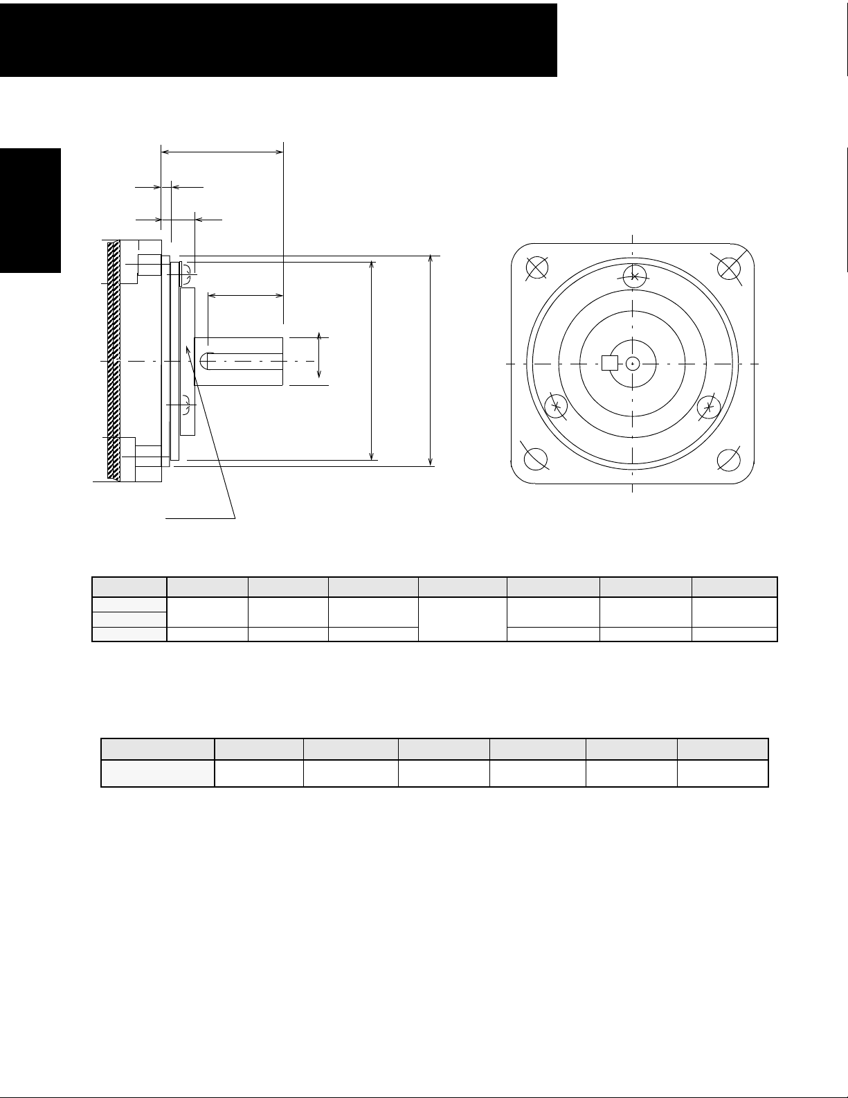
Page 35

100/200V Single-phase Sigma II Servo Systems
(2) 13-Bit Incremental or 16-Bit Absolute Encoder, with Brake
Note: 1. The keyway complies with JIS B1301-1976 (precision). A straight key is supplied.
2. The electromagnetic brake is only to hold the load in position and cannot be used to stop the motor.
3. Conforms to the IP67 enclosure, excluding the shaft (optional shaft seal available).
• 100W (0.13hp)
11.81 (300) ±1.18 (30)
Encoder cable
UL20276 Φ0.24 (6)
MOTOR cable
Encoder plug
SRUC 17GMRCN087
Motor Plug
SRUC 06JMSCN236
U
W
T
Cross-section Y - Y
Servomotors
SGMPH
Type SGMPH- L LL LM LR LG LC ΦLA ΦLZ ΦS* ΦLB**
01E4CD
Note: The quoted allowable radial load is the value at a position 0.79in (20mm) from the motor mounting surface.
†
Some motor dimensions vary for motors with the optional shaft seal: See p.38 for details.
Interconnection Connector Specifications
SRUC 17GMRCN087
0.35
(9.0)
Serial encoder
(Absolute or Incremental)
4.57
3.58
(116)
(91)
Encoder Plug
1
11
2
10
12
13
16
3
4
9
17
15
14
8
5
7
6
(Interconnectron)
Hexagonal nut
Opposite side width: 0.67 (17)
LC
0.83 (21)
A
4 -
Φ
Φ
LA
LZ
.
0.71 (18)
maximum
0.28 (7)
11.81 (300) ±1.18 (30)
L
LL
LM
LR
0.41 (10.5)
0.12 (3)
LG
0.0016 (0.04) A
Φ
0.0016 (Φ0.04)
QK
0.51
(13)
1.67
(42.5)
0.98
(25)
0.90
(23)
Magnetic brake: Non-excitation operation
DC power supply: 24V
0.24
2.36
2.76
0.22
(6)
(60)
(70)
(5.5)
0.315
(8)
Y
Y
QK U W T
1.968
0.55
(50)
(14)
S*
Φ
0.071
(1.8)
Key
LB**
Φ
0.12
(3)
A
0.0008 (0.002)
Voltage
0.12
(3)
(V)
200
Output
W (hp)
100
(0.13)
Torque
in•lb
(N•m)
2.81
(0.318)
Time
Rating
Contin-
uous
Specified Tolerances
Dimension
*ΦS **ΦLB
Unit Diameter Tolerance Diameter Tolerance
in 0.3150 +0.0000-0.0004 1.9685 +0.0000 -0.0010
mm 8.000 +0.000 -0.009 50.000 +0.000 -0.025
Incremental Terminal Specifications
Pin Number Description Color
1* Battery - 2* Battery * (3.6V)
3 Data + Blue
4Data− Blue/White
5 - 7, 10 - 17 Free -
8 +5V (Power Supply) Red
9 0V (Power Supply) Black
Connector Case FG (Frame Ground) Shield wire
*Note: Incremental Terminal pins number 1 and 2 are connectors
used for 16-bit absolute encoder option only.
Mating Connector: SPNA17HFRON16900E3 (Interconnectron)
Motor Plug
1
6
2
4
3
SRUC 06JMSCN236
(Interconnectron)
Motor Wiring Specifications
Pin Number Description Color
1 Phase U Red
5
2 Phase V White
3Phase WBlue
4 Holding Brake Black
5 Holding Brake Black
6 FG (Frame Ground) Green/Yellow
Mating Connector: SPNA06KFSDN169
LC
Rated
Approx
Speed
Mass
(rpm)
lb (kg)
1.5
3000
(0.7)
(Interconnectron)
Allowable
Radial
Load
lb (N)
17.5
(78)
Allowable
Thrust
Load
lb (N)
11.0
(49)
34
Page 36

100/200V Single-phase Sigma II Servo Systems
• 200W (0.27hp), 400W (0.53hp)
Encoder cable
UL20276 Φ0.24 (6)
0.35
0.51
(9.0)
(13)
Motor cable
0.28 (7)
0.33 (8.5)
11.81 (300) ±1.18 (30)
11.81 (300) ±1.18 (30)
L
LL
LM
0.90
(23)
LG
LR
0.12 (3)
QK
Y
Y
Encoder plug
SRUC 17GMRCN087
Motor Plug
SRUC 06JMSCN236
Φ
0.0016 (Φ0.04)
ΦLB**
ΦS*
HEXAGONAL NUT
Opposite side width: 0.67 (17)
0.0016 (0.04) A
A
Φ
LZ
U
W
T
Cross-section Y-Y
LC
0.83 (21)
0.71 (18)
maximum
SGMPH
Servomotors
LC
ΦLA
Serial encoder
(Absolute or Incremental)
Magnetic brake: Non-excitation operation
DC power supply: 24V
Key
Type SGMPH- L LL LM LR LG LC ΦLA ΦLZ ΦS* ΦLB**
5.06
3.88
02E4CD
04E4CD
(128.5)
5.85
(148.5)
(98.5)
4.67
(118.5)
1.89
(48.1)
2.68
(68.1)
1.18
(30)
0.31
(8)
3.15
(80)
3.54
(90)
0.28
(7)
0.551
(14)
Note: The quoted allowable radial load is the value at a position 0.98in (25mm) from the motor mounting surface.
†
Some motor dimensions vary for motors with the optional shaft seal: See p.38 for details.
Dimension
*ΦS **ΦLB
Unit Diameter Tolerance Diameter Tolerance
in 0.5512 +0.0000-0.0004 2.7559 +0.0000 -0.0012
mm 14.000 +0.000 -0.011 70.000 +0.000 -0.030
Interconnection Connector Specifications: See p.33.
QK U W T
2.756
0.63
0.12
(70)
(16)
0.20
(3)
Specified Tolerances
0.20
(5)
A
0.0008 (0.002)
Volt ageVOutput
(5)
200
400
W (hp)
200
(0.27)
400
(0.53)
Tor q ue
in•lb
( N•m)
5.64
(0.637)
11.2
(1.27)
Time
Rating
Contin-
uous
Rated
Speed
(rpm)
3000
Approx
Mass
lb (kg)
4.2
(1.9)
5.7
(2.6)
Allowable
Radial
Load lb
(N)
55.1
(245)
Allowable
Thrust
Load
lb (N)
15.29
(68)
35
Page 37

100/200V Single-phase Sigma II Servo Systems
• 750W (1.01hp)
Servomotors
SGMPH
Serial encoder
(Absolute or Incremental)
0.35
(9.0)
Encoder cable
UL20276 Φ0.24 (6)
0.28 (7)
0.51
(13)
11.81 (300) ±1.18 (30)
Motor cable
11.81 (300) ±1.18 (30)
L
LL
LM
LR
0.0016 (0.04) A
0.41 (10.5)
LG
0.14 (3.5)
Φ
QK
1.0
(25.5)
Magnetic brake: Non-excitation operation
DC power supply: 24V
Y
S*
Φ
Y
Encoder plug
SRUC 17GMRCN087
Motor Plug
SRUC 06JMSCN236
0.0016 (Φ0.04)
LB**
Φ
A
W
Cross-section Y - Y
Hexagonal nut
Opposite side width: 0.55 (14)
A
4 - ΦLZ
0.0008 (0.002)
U
T
LC
1.5 (38)
.
1.1 (28)
maximum
LC
Φ
Φ
LA
Type SGMPH- L LL LM LR LG LC ΦLA ΦLZ ΦS* ΦLB**
6.42
4.84
2.63
1.57
0.39
4.72
5.71
0.39
0.63
08E4CD
(163)
(123)
(66.7)
(40)
(10)
(120)
(145)
(10)
(16)
4.33
(110)
Key
QK U W T
0.87
0.12
(22)
0.20
(3)
(5)
0.20
(5)
Vol tageVOutput
W (hp)
750
200
(1.01)
Note: The quoted allowable radial load is the value at a position 1.38in (35mm) from the motor mounting surface.
†Some motor dimensions vary for motors with the optional shaft seal: See p.38 for details.
Specified Tolerances
Dimension
Unit Diameter Tolerance Diameter Tolerance
in 0.6299 +0.0000-0.0004 4.3307 +0.0000 -0.0014
mm 16.000 +0.000 -0.011 110.000 +0.000 -0.035
Interconnection Connector Specifications: See p.33.
*ΦS **ΦLB
.
Tor q u e
in•lb
(N•m)
21.15
(2.39)
Time
Rating
Contin-
uous
Rated
Speed
(rpm)
3000
Approx
Mass
lb (kg)
12.6
(5.7)
Allowable
Radial
Load lb
(N)
88.1
(392)
Allowable
Thrust
Load
lb (N)
33.0
(147)
36
Page 38

• 1500W (2.0hp)
Encoder cable
UL20276 Φ0.24 (6)
11.81 (300) ±1.18 (30)
Motor cable
100/200V Single-phase Sigma II Servo Systems
Encoder plug
SRUC 17GMRCN087
Motor Plug
SRUC 06JMSCN020
U
W
T
Cross-section Y - Y
11.81 (300) ±1.18 (30)
L
0.28
(7)
1.30 (33)
LL
LM
0.41 (10.5)
LG
LR
0.14 (3.5)
0.39
(10)
0.75
(19)
QK
Y
Y
4.33
(110)
0.35
0.51
(9.0)
(13)
Serial encoder
(Absolute or Incremental)
Type SGMPH- L LL LM LR LG LC ΦLA ΦLZ ΦS* ΦLB**
7.40
15E4CD
(188)
5.83
(148)
3.73
(94.7)
1.00
(25.5)
Magnetic brake: Non-excitation operation
DC power supply: 24V
1.57
0.39
4.72
(40)
(10)
(120)
5.71
(145)
Note: The quoted allowable radial load is the value at a position 1.38in (35mm) from the motor mounting surface.
†Some motor dimensions vary for motors with the optional shaft seal: See p.38 for details.
0.0016 (0.04) A
Φ
0.0016 (Φ0.04)
ΦS*
ΦLB**
Key
QK U W T
0.87
0.14
(22)
(3.5)
0.24
(6)
A
0.0008 (0.002)
VoltageVOutput
0.24
200
(6)
Specified Tolerances
Dimension
*ΦS **ΦLB
Unit Diameter Tolerance Diameter Tolerance
in 0.7480 +0.0000-0.0005 2.7559 +0.0000 -0.0014
mm 19.000 +0.000 -0.013 70.000 +0.000 -0.035
Interconnection Connector Specifications
Encoder Plug Motor Plug
1
11
2
12
13
16
3
17
15
14
4
5
7
6
SRUC 17GMRCN087
(Interconnectron)
Incremental Terminal Specifications
Pin Number Description Color
10
9
8
1* Battery - —
2* Battery * (3.6V) —
3 Data + Blue
4 Data − Blue/White
5 - 7, 10 - 17 Free —
8 +5V (Power Supply) Red
9 0V (Power Supply) Black
Connector Case FG (Frame Ground) Shield wire
*Note: Incremental Terminal pins number 1 and 2 are
connectors used for 16-bit absolute encoder option
only.
Mating Connector: SPNA17HFRON16900E3
(Interconnectron)
1
2
3
SRUC 06JMSCN020
(Interconnectron)
A
6
4
W (hp)
1500
(2.02)
5
Hexagonal nut
Opposite side width: 0.55 (14)
LC
1.50 (38)
1.1 (28)
Maximum
To rq u e
in•lb
( N•m)
42.1
(4.77)
Time
Rating
Contin-
uous
Rated
Speed
(rpm)
3000
Approx
Mass
lb (kg)
17.9
(8.1)
Allowable
Radial
Load
lb (N)
110
(490)
Motor Wiring Specifications
Pin
Description Color
No.
1 Phase U Red
2 Phase V White
3Phase W Blue
4 Holding Brake Black
5 Holding Brake Black
6 FG (Frame Ground) Green/Yellow
Mating Connector: SPNA06KFSDN169
(Interconnectron
LC
Allowable
Thrust
Load
lb (N)
33.0
(147)
SGMPH
Servomotors
37
Page 39

100/200V Single-phase Sigma II Servo Systems
Dimension Modifications for Motors with Optional Shaft Seal
LR
LE
LD
QK
LB
Servomotors
SGMPH
ΦS
LP
Φ
Shaft Seal
Type SGMPH- QK
01 0.55 (14) 1.97 (50) 0.31 (8)
02
04
08
15 0.75 (19)
*Refer to the following table for tolerances for diameters LB and S.
0.64 (16) 2.76 (70) 0.55 (14) 1.18 (30) 0.39 (10) 1.93 (49)
0.87 (22) 4.33 (110)
Dimension
Unit Diameter To le r an c e Diameter To l er a nc e
in
mm
ΦLB* ΦS*
0.63 (16)
Specified Tolerances
*ΦS **ΦLB
0.3150 +0.0000-0.0004 1.9685 +0.0000 -0.0010
0.5512 +0.0000-0.0004 2.7559 +0.0000 -0.0014
0.6299 +0.0000-0.0004 4.3307 +0.0000 -0.0014
0.7480 +0.0000-0.0005
8.000 +0.000 -0.009 50.000 +0.000 -0.025
14.000 +0.000 -0.011 70.000 +0.000 -0.035
16.000 +0.000 -0.011 110.000 +0.000 -0.035
19.000 +0.000 -0.013
Torque Reduction Factor for SGMPH motors equipped with a shaft seal:
LE LR LD
0.98 (25) 0.28 (7) 1.54 (39)
0.12 (3)
0.14 (3.5) 1.57 (40) 0.41 (10.5) 3.03 (77)
ΦLP
Servo Motor Model 01 02 04 08 15
Torque Reduction
Factor
90% 90% 95% 95% 95%
For Example: The SGMPH-01 continuous and peak torque rating should be reduced to
90% of the listed catalog specification.
To specify a motor with a shaft seal, refer to the motor part number explanation on the
following page.
38
Page 40

100/200V Single-phase Sigma II Servo Systems
Selecting Your SGMPH Sigma II Servo System
First, select the Sigma II servomotor suited for your application using SigmaSize: the Yaskawa
servomotor sizing software, available at no charge. (Request SigmaSize software via e-mail, at:
literature@yaskawa.com).
Use the diagram below to locate and identify the components of your system. Each item is lettercoded and cross-referenced in the option tables on the following pages.
System Configuration
Digital Operator (E)
3CN
Peripheral
Signal
Cable (E)
1CN
I/O Signal
Connector
(D)
SGDH Servo
Amplifier
(B)
Regenerative Unit (E)
Model Number Designation
5CN
For Monitor (D)
Connector
Encoder (D)
Encoder side
Connector (D)
2CN
Encoder Cable (C)
Motor Cable (C)
Optional Holding Brake
Shaft Keyway
SGMPH
Servomotor
(A)
Shaft Seal
Motor side
Connector (D)
Specify a technical manual, if it is needed, on your
servo system purchase order:
Sigma II Series Servo System User’s Manual: YEA-SIA-S800-32.2
(Manual is provided at no charge with a purchase order,
but it must be requested).
SGMPH
Servomotors
Sigma Servomotor Type
Rated Output
01: 100W (0.13hp)
02: 200W (0.25hp)
04: 400W (0.5hp)
08: 750W (1hp)
15: 1.5kW (2hp)
Power Supply
A: 200V UL Recognized
B: 100V UL Recognized
SGMPH - 01 A A E 4 1D
Accessories
1D: Standard
CD: Standard with 24V
SD: Standard with Shaft Seal
ED: Standard with Brake & Shaft Seal
Shaft Specifications
4: Straight Shaft with Keyway
Revision Level
Encoder Specifications
A: 13-Bit (2048 x 4) Incremental Encoder
1: 16-Bit (16,384 x 4) Absolute Encoder
Holding Brake
DC
39
Page 41

100/200V Single-phase Sigma II Servo Systems
Servomotor & Amplifier Selection
Use the table below to select the appropriate SGMPH Sigma II servomotor and amplifier.
(Refer to the motor model # designation on the previous page specifying the available modification to motor
construction/features.)
Servomotors
SGMPH
Description
200V
13-Bit Incremental
Encoder
Straight Shaft with
Keyway
5000rpm
Pre-wired with
Heavy Duty
Connectors
Peak
To rq u e
(oz • in)
135 45.1
270 90.1
542 181
1010 338
2027 676
Torque
(oz • in)
Rated
Motor Inertia
(oz • in • s
2
x10-3)
0.917
1.46
2.96 SGMPH-02AAE41D
4.35
4.92
6.31 SGMPH-04AAE4CD
29.9
35.7
57.1 SGMPH-15AAE41D
67.8
Motor MODEL # (A)
SGMPH-01AAE41D
SGMPH-01AAE4CD
SGMPH-02AAE4CD
SGMPH-04AAE41D
SGMPH-08AAE41D
SGMPH-08AAE4CD
SGMPH-15AAE4CD
Amplifier MODEL # (B)*
1-Phase
SGDH-
01AE —
02AE —
04AE —
08AE-S 08AE
15AE-S 15AE
3-Phase
SGDH-
Motor &
Amplifier
Item Class
Stock
100V, 1-Phase
13-Bit Incremental
Straight Shaft with
Pre-wired with
Notes: 24V
40
SGMPH-01BAE41D
01BE —
SGMPH-01BAE4CD
SGMPH-02BAE41D
02BE —
SGMPH-02BAE4CD
SGMPH-04AAE41D
04FE —
SGMPH-04AAE4CD
Encoder
Keyway
5000rpm
Heavy Duty
Connectors
DC
0.917
135 45.1
1.46
2.96
270 90.1
4.35
4.92
542 181
6.31
brakes for SGMPH Sigma II servomotors are standard. Contact a local source for 24VDC power supplies. Motor power
and encoder cables are factory pre-wired with approximately 13” lead length with heavy duty mating connectors.
Use the tables on the following page to specify mating connectors and/or various cable lengths.
For technical information, request Yaskawa manual number YEA-SIA-S800-32.2.
* For more detailed SGDH amplifier specifications and dimensions, refer to pages 99 to 112.
Page 42

100/200V Single-phase Sigma II Servo Systems
Pre-wired Cable Selection
Use the table below to select pre-wired cables for your SGMPH Sigma II servomotor.
Cable Description (C)
Power Cable with Interconnectron Connectors
(without Brake)
Power Cable with Interconnectron Connectors
(with Brake)
(IP67)
Encoder Cable with Interconnectron Connector
(incremental or absolute)
(IP67)
Encoder Cable
(for applications
up to 20m)
Only for Solder
Connections
Encoder Cable
(for applications
from >20 to <50m)
Only for Solder
Connections
Motor Size
(kW)
0.1, 0.2,
0.4, 0.8
1.5
0.1, 0.2,
0.4, 0.8
1.5
All
Part Number* Comments
B4ICE-(A)
B5ICE-(A)
B4IBCE-(A)
B5IBCE-(A)
A1ICE-(A)
FR-RMCT-SB
UL20276-SB
These UL and CE compliant cables are available in
five lengths. Use two digits
in the part number’s last
place:
03: 3m
05: 5m
10: 10m (standard)
15: 15m
20: 20m
These cables are available in any length.
For example, to order one
FR-RMCT-SB cable, 16m
long,
specify:
quantity:16
part no.: FR-RMCT-SB
Item
Class
SGMPH
Servomotors
Stock**
Input/Output 1CN Cable &
Transition
Terminal Block
Input/Output 1CN Cable with
Pigtail Leads
Input/Output 1CN Cable
Cable with Female
D-Sub output Connector***
JUSP-TA50P
JZSP-CKI01-(A)
JZSP-CKI0D-
35mm DIN rail mountable;
the cable length is 0.5
meters.
Use the following key to
specify required cable
length (last digit of part
number):
1: 1m (standard)
2: 2m
3: 3m
Use the following key to
specify required cable
length (last two digits of the
part number):
D50: 0.5m
01: 1m (standard)
02: 2m
03: 3m
* The “(A)” at the end of the cable part number is the revision level. Revision level may be changed prior to catalog reprinting.
** Standard cable lengths are Stock items; non-standard cable lengths are Limited Stock items.
*** 50 Pin Female D-Sub output connector mates to customer supplied third party terminal block. (e.g., Wago #289-449,
Weidmuller #919658, Phoenix #2283647, Amphenol/Sine #20-51039, and many others)
41
Page 43

100/200V Single-phase Sigma II Servo Systems
Connector Selection
Use the table below to select mating connectors or kits for your SGMPH Sigma II servomotor.
Interconnectron
Connector for Motor
Power Cable (with or
without Brake)
(IP67)
Servomotors
SGMPH
2CN Amplifier
Mating Connector
Interconnectron
Connector for Encoder
Cable
(incremental or
absolute encoder)
(IP67)
1CN Mating
Connector
Connector Description (D)
Motor Size
(kW)
0.1, 0.2,
0.4, 0.8,
1.5
Part Number Comments
FIN07S-B2 Solder Cup
JZSP-CMP9-1 —
FIN17C-A2
JZSP-CKI9 –
Gauge: 24 - 18AWG
Requires Crimp Tool
B150 and positioner.
Item
Class
Stock
Interconnectron
Crimp Tool
Positioner —
All
—
B150 —
B055/A —
Limited
Stock
42
Page 44

100/200V Single-phase Sigma II Servo Systems
Peripheral Device Selection
Use the table below to select peripheral devices for your SGMPH Sigma II servomotor.
Component Description (E) Part Number Comments Item Class
Hand-held Digital
Operator Panel
Absolute Encoder Battery
Software Interface Cable —
SigmaWin+ Software
For: SGDH-01AE
Individual External Regenerative Unit
For: SGDH-15AE
For 200V: SGDH-01AE
DC Reactor
(for suppressing harmonics
in the power supply)
For 100V: SGDH-01BE
SGDH-02AE
SGDH-04AE
SGDH-08AE
SGDF-08AE-S
amps
SGDH-15AE-S
SGDH-02AE
SGDH-04AE
SGDH-08AE
SGDF-08AE-S
SGDH-15AE
SGDH-15AE-S
SGDH-02BE
JUSP-OP02A-1
and
JZSP-CMS00-1
JZSP-BA01 3.6V, 1000mAh (lithium battery)
YS-12
JZSP-WP0001
RH12050ohmJ
RH500N25_ohmΚ
X5071
X5070
X5069
X5061
X5079
X5060
X5078
X5063
X5062
Portable unit with 1m adapter cable for
Sigma II
Pre-wired 2.0m cable with
9-pin connector
Minimum Recommended System
Requirements Pentuim 200 MHz,
64MB RAM, 200MB hard drive,
CDROM Drive, RS-232 or RS-422
port, Screen rsolution 800x600 w/ 256
colors, and Windows
95,98,NT4.0,2000,ME. (Windows XP
planned)
These are general purpose regenerative units.*
Caution: Proper set-up is necessary
to avoid equipment damage.
—
* For an alternate solution, specify the individual resistor part number RH500N25_OHMK in necessary series or parallel connection.
Refer to the SGDH servo amplifier section of this catalog for additional specifications, and the Sigma II Series Servo System User’s
Manual (YEA-SIA-S800-32.2) for proper resistor sizing guidelines.
Stock
Limited
Stock
SGMPH
Servomotors
43
Page 45

100/200V Single-phase Sigma II Servo Systems
NOTES:
Servomotors
SGMPH
44
Page 46

100/200V Single-phase Sigma II Servo Systems
SGMPH Gearmotors - With Incremental / Absolute Encoder
Rated Output : 100W, 200W, 400W,
750W, 1500W
For Additional Information
SGMPH Gearmotor Ratings & Specifications
SGMPH Gearmotor Dimensions
SGMPH Gearmotor Selection/Ordering Information
SGDH Ratings & Specifications
SGDH Dimensions
Design Features
1. Compact Construction
z Easy to install - pre-engineered and pre-assembled
z Ideal for cyclic and reversing applications
z Fits in limited mounting space
z Planetary gear geometry allowing high output torques in a compact package
2. Torque
z 40.9 to 3540in • lb peak torque
z Cost-effective solution for low speed and high torque applications
z Gear ratios - 5:1 to 100:1 in some sizes
z High torsional stiffness and low backlash
z Lubrication is self-replenishing to ensure long life
3. Encoders
z 13-Bit (2,048ppr x 4) incremental encoder (standard)
z 16-Bit (16,384ppr x 4) absolute encoder (option)
4. Enclosure
z Motor is totally enclosed, self-cooled IP67 (not including shaft)
5. Application Emphasis
z PCB drilling machines
z Robots
z Conveyors
z Packaging machines
6. Certified International Standards
z UL, cUL recognized (File #: E165827), CE compliance
Page(s)
48 - 49
50 - 51
52 - 55
99 - 100
101 - 112
SGMPH
Gearmotors
45
Page 47

100/200V Single-phase Sigma II Servo Systems
Gearmotor Ratings and Specifications
Gearmotors
SGMPH
GEARMOTOR
Part Number
SG05SA-PE01
SG10SA-PE01
SG25SA-PE01
SG50SA-PE01
SG1ASA-PE01
SG05SA-PE02
SG10SA-PE02
SG25SA-PE02
SG50SA-PE02
SG1ASAPE02
SG05SA-PE04
SG10SA-PE04
SG25SA-PE04
SG50SA-PE04
SG1ASA-PE04
SG05SA-PE08
SG10SA-PE08
SG25SA-PE08
SG50SA-PE08
SG05SA-PE15
SG10SA-PE15
SG25SA-PE15
SG50SA-PE15
* Values for 100V Gearmotor
Note: 1. These performance ratings apply when duty cycles are 60% or less, and when the gearmotor runs for 1,000
cycles per hour or less. Contact your Yaskawa representative when duty cycles exceed 60%, and when the gearmotor runs for more than 1,000 cycles per hour.
2. Rated Speed is at 20°C ambient temperature. Reduce Rated Speed by 20% at 40°C ambient temperature.
3. For right-angle gearmotors, please consult the factory for availability.
Rated
Torque
• lb)
(in
13.67 40.93 600 1000 900 8.59 34.34
27.34 81.84 300 500 450 17.17 68.68
66.95 200.39 120 200 180 42.04 168.16
133.89 283.00 60 100 90 84.08 336.32
267.78 637.00 30 50 45 168.16 672.65
27.34 81.84 600 1000 1000/600 17.17 81.8/36.2*
54.68 163.69 300 500 500/300 34.34 163.7/72.4*
133.89 283.00 120 200 200/120 84.08 283/177*
267.78 708.00 60 100 100/60 168.16 708/354.7*
535.56 1593.00 26 48 50/30 336.32 1593/704.4*
54.81 164.42 600 1000 640 34.34 77.27
109.61 283.00 300 500 320 68.68 154.53
268.38 708.00 120 200 128 168.16 378.36
536.75 1610.25 52 96 64 336.32 756.73
1073.50 2832.00 20 36 32 672.65 1513.45
102.34 306.04 600 1000 640 51.51 51.51
204.67 612.07 300 500 320 103.02 103.02
501.13 1498.63 104 192 128 252.24 252.24
1002.25 2997.25 40 72 64 504.48 504.48
205.16 614.50 520 960 640 103.02 103.02
410.31 1228.99 260 480 320 206.04 206.04
1004.63 3009.13 80 144 128 504.48 504.48
2009.25 3540.00 40 72 64 1008.97 1008.97
Peak
Torque
• lb)
(in
Rated
Speed
(rpm)
Maximum
Speed
(rpm)
Speed
N1
(rpm)
Torque
T1
• lb)
(in
Torque
T2
• lb)
(in
Amplifier Model
Number
Analog Input
SGDH-
01
02
04
08
15
46
Peak Torque
Rated Torque
Torque
T2
T1
B
A
Rated Speed
N1
Maximum Speed
A = Continuous Duty
B = Intermittent Duty
Speed
Page 48

100/200V Single-phase Sigma II Servo Systems
Gearmotor Mechanical Ratings
GEARMOTOR
Part Number
SG05SA-PE01
SG10SA-PE01
SG25SA-PE01
SG50SA-PE01
SG1ASA-PE01
SG05SA-PE02
SG10SA-PE02
SG25SA-PE02
SG50SA-PE02
SG1ASA-PE02
SG05SA-PE04
SG10SA-PE04
SG25SA-PE04
SG50SA-PE04
SG1ASA-PE04
SG05SA-PE08
SG10SA-PE08
SG25SA-PE08
SG50SA-PE08
Gearhead
Backlash
(arc min)
<10
<10
<10
<10
Gearhead
Maximum Radial
Load (lb
)
f
146 158 0.000052 3.24
326 349 0.00025 6.39
540 428 0.0016 12.79
326 349 0.00025
540 428 0.0016 14.34
1035 900 0.0049 27.79
326 349 0.00025 8.82
540 428 0.0016 15.88
1035 900 0.0049 29.33
1687 1350 0.0047 50.83
540 428 0.0016 19.18
1035 900 0.0049 34.84
1687 1350 0.0047 56.34
Gearhead
Maximum Axial
Load (lb
)
f
Gearhead
Inertia
• lb • s
(in
2
)
Gearmotor
Weight
(lb)
7.28
7.94
SG05SA-PE15
SG10SA-PE15
SG25SA-PE15
SG50SA-PE15
<10
TORSIONAL ANGLE
REDUCER’S BACKLASH
1035 900 0.0048 34.40
1687 1350 0.0047 60.75
CONVENTIONAL GEARMOTOR
YASKAWA
Sigma II
GEARMOTOR
TORQUE
2% OF RATED TORQUE
SGMPH
Gearmotors
47
Page 49

100/200V Single-phase Sigma II Servo Systems
Dimensions in inches (mm)
Gearmotors
SGMPH
Motor leads extend 11.81in (300mm) from motor
LL
LL3
LR
Q
QK
T
(4) Holes 90° apar
MT
threaded
MD
deep
KD
t
U
LC
W
T
LE
øGD
0.472
(12)
0.630
(16)
0.866
(22)
0.630
(16)
0.866
(22)
1.260
(32)
0.630
(16)
0.866
(22)
1.260
(32)
1.575
(40)
0.866
(22)
1.260
(32)
1.575
(40)
1.260
(32)
1.575
(40)
øLB
2.362
(60)
2.756
(70)
3.543
(90)
3.150
(80)
3.543
(90)
4.724
(120)
3.150
(80)
3.543
(90)
4.724
(120)
1.732
(44)M4x 0.7
2.441
(62)M5x 0.8
3.150
(80)M6x 1.0
2.441
(62)M5x 0.8
3.150
(80)M6x 1.0
4.252
(108)
1.25
2.441
(62)M5x 0.8
3.150
(80)M6x 1.0
4.252
(108)
1.25
5.512
M10
(140)
x 1.5
3.150
(80)M6x 1.0
4.252
(108)
1.25
5.512
M10
(140)
x 1.5
4.252
(108)
1.25
5.512
M10
(140)
x 1.5
M8
M8
M8
M8
0.315
0.709
(18)
1.102
(28)
1.417
(36)
1.102
(28)
1.417
(36)
2.284
(58)
1.102
(28)
1.417
(36)
2.284
(58)
3.228
(82)
1.417
(36)
2.284
(58)
3.228
(82)
2.284
(58)
3.228
(82)
0.551
(14)
0.984
(25)
1.260
(32)
0.984
(25)
1.260
(32)
1.969
(50)
0.984
(25)
1.260
(32)
1.969
(50)
2.756
(70)
1.260
(32)
1.969
(50)
2.756
(70)
1.969
(50)
2.756
(70)
0.079
0.158
0.079
0.158
0.236
0.079
0.158
0.236
0.158
0.236
(8)
0.394
(10)
0.472
(12)
0.394
(10)
0.472
(12)
0.630
x
(16)
0.394
(10)
0.472
(12)
0.630
x
(16)
0.787
(20)
0.472
(12)
0.630
x
(16)
0.787
(20)
0.630
x
(16)
0.787
(20)
øS
GEARMOTOR LL3 LL LE LR LB GD S LC LA MT MD Q QK KD W T U
SG05SA-PE01A
SG10SA-PE01A
SG25SA-PE01A
SG50SA-PE01A
SG1ASA-PE01A
SG05SA-PE02A
SG10SA-PE02A
SG25SA-PE02A
SG50SA-PE02A
SG1ASA-PE02A
SG05SA-PE04A
SG10SA-PE04A
SG25SA-PE04A
SG50SA-PE04A
SG1ASA-PE04A
SG05SA-PE08A
SG10SA-PE08A
SG25SA-PE08A
SG50SA-PE08A
SG05SA-PE15A
SG10SA-PE15A
SG25SA-PE15A
SG50SA-PE15A
1.988
(50)
3.465
(88)
4.193
(106.5)
2.677
(68)
3.465
(88)
4.193
(106.5)
5.295
(134.5)
2.677
(68)
4.193
(106.5)
5.295
(134.5)
6.024
(153)
3.150
(80)
5.295
(134.5)
6.024
(153)
4.016
(102)
6.024
(153)
5.177
(131.5)
6.858
(174.2)
7.500
(190.5)
6.181
(157)
6.969
(177)
7.697
(195.5)
9.036
(229.5)
6.969
(177)
8.484
(215.5)
9.823
(249.5)
10.551
(268.0)
7.815
(198.5)
9.803
(249)
10.532(
267.5)
9.626
(244.5)
11.634
(295.5)
0.158
(4)
0.197
(5)
0.236
(6)
0.197
(5)
0.236
(6)
0.315
(8)
0.197
(5)
0.236
(6)
0.315
(8)
0.236
(6)
0.315
(8)
0.965
(24.5)
1.417
(36)
1.811
(46)
1.417
(36)
1.811
(46)
2.756
(70)
1.417
(36)
1.811
(46)
2.756
(70)
3.819
(97)
1.811
(46)
2.756
(70)
3.819
(97)
2.756
(70)
3.819
(97)
1.378
(35)
2.047
(52)
2.677
(68)
2.047
(52)
2.677
(68)
3.543
(90)
2.047
(52)
2.677
(68)
3.543
(90)
4.724
(120)
2.677
(68)
3.543
(90)
4.724
(120)
3.543
(90)
4.724
(120)
1.969
(50)
2.756
(70)
3.543
(90)
2.756
(70)
3.543
(90)
4.724
(120)
2.756
(70)
3.543
(90)
4.724
(120)
6.102
(155)
3.543
(90)
4.724
(120)
6.102
(155)
4.724
(120)
6.012
(155)
øLA
0.158
0.158
(4)
0.197
0.197
(5)
0.236
0.236
(6)
(2)
0.197
0.197
(5)
0.236
0.236
(6)
0.394
(10)
0.197
(5)
0.236
(6)
0.394
(10)
0.472
(12)
0.236
(6)
0.394
(10)
0.472
(12)
0.394
(10)
0.472
(12)
0.315
0.197
0.236
0.315
0.236
0.315
(4)
(2)
(4)
(6)
(2)
(4)
(6)
(4)
(6)
0.098
(4)
(2.5)
0.118
(5)
(3)
0.138
(6)
(3.5)
0.118
(5)
(3)
0.138
(6)
(3.5)
0.197
(8)
(5)
0.118
(5)
(3)
0.138
(6)
(3.5)
0.197
(8)
(5)
0.138
(6)
(3.5)
0.197
(8)
(5)
48
Page 50

100/200V Single-phase Sigma II Servo Systems
Tolerances for standard (SG) gearmotors
Dimension ΦS ΦLB W
Unit Diameter Tolerance Diameter To le ra nc e Width Tol e ra n ce
0.472, 0.630 +0.00047 +0.00004 1.378 +0.00000 -0.00063 0.158, 0.197, 0.236 +0.00000 -0.00118
in
mm
0.866 +0.00059 +0.00008 2.047, 2.677 +0.00000 -0.00075 0.39370 +0.00000 -0.00142
1.25984, 1.57480 +0.00071 +0.00008 3.5433, 4.724 +0.00000 -0.00087 0.47244 +0.00000 -0.00169
12, 26 +0.012 +0.001 35 +0.000 -0.016 4, 5, 6 +0.000 -0.030
22 +0.015 +0.002 52, 68 +0.000 -0.019 10 +0.000 -0.036
32, 40 +0.018 +0.002 90, 120 +0.000 -0.022 12 +0.000 -0.043
49
SGMPH
Gearmotors
Page 51

100/200V Single-phase Sigma II Servo Systems
Selecting Your SGMPH Gearmotor System
First, select the Sigma II servomotor suited for your application using SigmaSize: the Yaskawa
servomotor sizing software, available at no charge. (Request SigmaSize software via e-mail, at:
literature@yaskawa.com).
Use the diagram below to locate and identify the components of your system. Each item is lettercoded and cross-referenced in the option tables on the following pages.
System Configuration
Gearmotors
SGMPH
Digital Operator (E)
3CN
Peripheral
Signal
Cable (E)
1CN
I/O Signal
Connector
(D)
Regenerative Unit (E)
SGDH Servo
Amplifier
(B)
Model Number Designation
SG 05 S A-PE 02 A A C
Sigma II Gearmotor Series
G: Standard (<10 arc min)
Reduction Ratio
05: 5:1
10: 10:1
25: 25:1
50: 50:1
1A: 100:1
Construction
S: Standard
Revision Level
Motor Series
PE: SGMPH
5CN
For Monitor (D)
Connector for
Encoder Signal (D)
Encoder side
Connector (D)
2CN
Encoder Cable (C)
Motor Cable (C)
SGMPH
Gearmotor
(A)
Motor side
Connector (D)
Shaft w/Keyway
Specify a technical manual, if it is needed, on your
servo system purchase order:
Sigma II Series Servo System User’s Manual: YEA-SIA-S800-32.2
(Manual is provided at no charge with a purchase order,
but it must be requested).
Accessories
C: 24V
Blank:Standard YEA stock motor
Encoder Specifications
A: 13-Bit Incremental Encoder
1: 16-Bit Absolute Encoder
Power Supply
A: 200V
B: 100V
Motor Output
01: 100W (0.13hp)
02: 200W (0.25hp)
04: 400W (0.5hp)
08: 750W (1hp)
15: 1.5kW (2hp)
DC
options
Brake
50
Page 52

100/200V Single-phase Sigma II Servo Systems
Gearmotor & Amplifier Selection
Use the table below to select the appropriate SGMPH Sigma II gearmotor and amplifier.
(Refer to the motor model # designation on the previous page specifying the available modification to motor construction/features.)
Gearmotor (A) Gearhead only
Rated
MODEL #
SG05SA-PE01AA 13.67 40.93 600 1000
SG10SA-PE01AA 27.34 81.84 300 500 10:1
SG25SA-PE01AA 66.95 200.39 120 200
SG50SA-PE01AA 133.89 283.00 60 100 50:1
SG1ASA-PE01AA 267.78 637.00 30 50 0.0016 100:1
SG05SA-PE02AA 27.34 81.84 600 1000
SG10SA-PE02AA 54.68 163.69 300 500 10:1
SG25SA-PE02AA 133.89 283.00 120 200 25:1
SG50SA-PE02AA 267.78 708.00 60 100 0.0016 50:1
SG1ASA-PE02AA 535.56 1593.00 26 48 0.0049 100:1
SG05SA-PE04AA 54.81 164.42 600 1000
SG10SA-PE04AA 109.61 283.00 300 500 10:1
SG25SA-PE04AA 268.38 708.00 120 200
SG50SA-PE04AA 536.75 1610.25 52 96 50:1
SG1ASA-PE04AA 1073.50 2832.00 20 36 0.0047 100:1
SG05SA-PE08AA 102.34 306.04 600 1000
SG10SA-PE08AA 204.67 612.07 300 500 10:1
SG25SA-PE08AA 501.13 1498.63 104 192 0.0049 25:1
SG50SA-PE08AA 1002.25 2997.25 40 72 0.0047 50:1
SG05SA-PE15AA 205.16 614.50 520 960
SG10SA-PE15AA 410.31 1228.99 260 480 10:1
SG25SA-PE15AA 1004.63 3009.13 80 144 0.0047 25:1
SG50SA-PE15AA 2009.25 3540.00 40 72 0.0047 50:1
SG05SA-PE01BA 13.67 40.93 600 1000
SG10SA-PE01BA 27.34 81.84 300 500 10:1
SG25SA-PE01BA 66.95 200.39 120 200
SG50SA-PE01BA 133.89 283.00 60 100 50:1
SG1ASA-PE01BA 267.78 637.00 30 50 0.0016 100:1
SG05SA-PE02BA 27.34 81.84 600 1000
SG10SA-PE02BA 54.68 163.69 300 500 10:1
SG25SA-PE02BA 133.89 283.00 120 200 25:1
SG50SA-PE02BA 267.78 708.00 60 100 0.0016 50:1
SG1ASA-PE02BA 535.56 1593.00 26 48 0.0049 100:1
Torque
(in • lb)
Peak
Torque
(in • lb)
Rated
Speed
(rpm)
Maximum
Speed
(rpm)
Inertia
(in • lb • s
0.000052
0.00025
0.00025
0.00025
0.0016
0.0016
0.0048
0.000052
0.00025
0.00025
Gear
2
Ratio
)
5:1
25:1
5:1
5:1
25:1
5:1
5:1
5:1
25:1
5:1
Amplifier
MODEL #
(B)*
SGDH-
01A
02A
04A
08A
15A
01B
02B
Gear
Motor
Item
Class
Normal
leadtime
3 - 4
weeks for
assembly
Amplifier
Item
Class
Stock
SGMPH
Gearmotors
Notes:24VDC Brakes for SGMPH Sigma II gearmotors are standard. Contact a local source for 24VDC power supplies.
Use the tables on the following page to specify mating connectors or pre-wired cables in different lengths.
For technical information, request Yaskawa technical bulletin number YEA-TSA-S800-16.16 and Yaskawa manual number
TSE-S800-15.
51
Page 53

100/200V Single-phase Sigma II Servo Systems
* For more detailed 100/200V SGDH amplifier specifications and dimensions, refer to pages 99 - 112.
.
Pre-wired Cable Selection
Use the table below to select pre-wired cables for your SGMPH Sigma II gearmotor.
Gearmotors
SGMPH
Cable Description (C)
Power Cable with Interconnectron Connectors
(without Brake)
Power Cable with Interconnectron Connectors
(with Brake)
Encoder Cable with Interconnectron Connector
(incremental or
absolute)
Encoder Cable
(for applications
up to 20m)
Only for Solder
Connections
Encoder Cable
(for applications
from >20 to <50m)
Only for Solder
Connections
Input/Output 1CN Cable &
Transition
Terminal Block
Motor Size
(kW)
0.1, 0.2,
0.4, 0.8
1.5
0.1, 0.2,
0.4, 0.8
1.5
All
Part Number* Comments
B4ICE-(A)
B5ICE-(A)
B4IBCE-(A)
B5IBCE-(A)
A1ICE-(A)
FR-RMCT-SB
UL20276-SB
JUSP-TA50P
These UL and CE compliant cables are available in
five lengths.Use the following key to specify
needed cable length (last
two digits of the part number):
03: 3m
05: 5m
10: 10m (standard)
15: 15m
20: 20m
These cables are available
in any length.
For example, to order one
FR-RMCT-SB cable, 16m
long, specify:
quantity: 16
part no.: FR-RMCT-SB
35mm DIN rail mountable;
the cable length is 0.5
meters.
Item
Class
Stock**
Use the following key to
specify required cable
Input/Output 1CN Cable with
Pigtail Leads
Input/Output 1CN Cable
Cable with Female
D-Sub output Connector***
JZSP-CKI01-(A)
JZSP-CKI0D-
length (last digit of part
number):
1: 1m (standard)
2: 2m
3: 3m
Use the following key to
specify required cable
length (last two digits of
the part
number):
D50: 0.5m
01: 1m (standard)
02: 2m
03: 3m
* The “(A)” at the end of the cable part number indicates the revision level. Revision level may be subject to change prior to this
catalog reprinting.
** Standard cable lengths are Stock items; non-standard cable lengths are Limited Stock items.
*** 50 Pin Female D-Sub output connector mates to customer supplied third party terminal block. (e.g., Wago #289-449,
Weidmuller #919658, Phoenix #2283647, Amphenol/Sine #20-51039, and many others)
52
Page 54

100/200V Single-phase Sigma II Servo Systems
Connector Selection
Use the table below to select mating connectors or kits for your SGMPH Sigma II gearmotor.
Connector Description (D)
Interconnectron
Connector for Motor
Power Cable (with or
without Brake)
2CN Amplifier
Mating Connector
Interconnectron
Connector for Encoder
Cable
(incremental or
absolute encoder)
1CN Mating
Connector
Motor Size
(kW)
0.1, 0.2,
0.4, 0.8,
1.5
All
Part Number Comments
FIN07S-B2
JZSP-CMP9-1 —
FIN17C-A2
JZSP-CKI9 —
IP67 Mated
Solder Cup
IP67 Mated
Gauge: 24 - 18 AWG
Requires Crimp Tool
B150 and positioner.
Item
Class
Stock
Interconnectron
Crimp Tool
Positioner —
—
B150 —
B055/A —
Limited
Stock
SGMPH
Gearmotors
53
Page 55

100/200V Single-phase Sigma II Servo Systems
Peripheral Device Selection
Use the table below to select peripheral devices for your SGMPH Sigma II gearmotor.
Gearmotors
SGMPH
Component Description (E) Part Number Comments
Hand-held Digital
Operator Panel
Software Interface Cable —
SigmaWin+ Software
Individual External Regenerative Unit
DC Reactor
(for suppressing harmonics
in the power supply)
For: SGDH-01AE
amps
For: SGDH-15AE
For 200V: SGDH-01AE
For 100V: SGDH-01BE
SGDH-02AE
SGDH-04AE
SGDH-08AE
SGDF-08AE-S
SGDH-15AE-S
SGDH-02AE
SGDH-04AE
SGDH-08AE
SGDF-08AE-S
SGDH-15AE
SGDH-15AE-S
SGDH-02BE
JUSP-OP02A-1
and
JZSP-CMS00-1
JZSP-BA01
YS-12
JZSP-WP0001
RH12050ohmJ
RH500N25_ohmΚ
X5071
X5070
X5069
X5061
X5079
X5060
X5078
X5063
X5062
Portable unit with 1m adapter
cable for Sigma II
3.6V, 1000mAh
(lithium battery)
Pre-wired 2.0m cable with 9pin connector
Minimum Recommended System Requirements Pentuim
200 MHz, 64MB RAM, 200MB
hard drive, CDROM Drive, RS232 or RS-422 port, Screen
rsolution 800x600 w/ 256 colors, and Windows
95,98,NT4.0,2000,ME. (Windows XP planned)
These are general purpose
regenerative units.*
Caution: Proper set-up is
necessary to avoid equipment
damage.
—
—
Item
Class
StockAbsolute Encoder Battery
Limited
Stock
* For an alternate solution, specify the individual resistor part number RH500N25_OHMK in necessary series or parallel connec-
tion. Refer to the SGDH servo amplifier section of this catalog (pages 97 to 126) for additional specifications, and the Sigma II
Series Servo System User’s Manual (YEA-SIA-S800-32.2) for proper resistor sizing guidelines.
54
Page 56

200V Three-phase Sigma II Servo Systems
General Purpose
SGMGH Servomotors - With Incremental / Absolute Encoder
Rated Output: 0.45kW, 0.85kW,
1.3kW, 1.8kW, 2.9kW,
4.4kW, 5.5kW, 7.5kW,
11kW, 15kW.
For Additional Information Page(s)
SGMGH
Servomotors
SGMGH Ratings & Specifications
SGMGH Speed/Torque Curves
SGMGH Dimensions
SGMGH Selection/Ordering Information
SGDH Ratings & Specifications
SGDH Dimensions
Design Features
1. Compact
z Small sized motor
Compatible with previous generation G series motors
Ten types of rated outputs ranging from 0.79 to 1988in
Optional built-in holding brake available
2. Higher Speed and acceleration
z Up to 3000rpm maximum
z High torque to inertia ratio
3. Encoders
z 17-bit (32,768 ppr x 4) incremental encoder (standard)
z 17-bit absolute encoder (optional)
4. Enhanced Environmental Resistance
z Totally enclosed, self-cooled IP67 (excluding shaft)
z Shaft seal (optional)
5. Application Emphasis
z Machine tools and woodworking machines
z Packagingmachines
z Gantry Robots
z Press Automation
z Thermoforming
6. Certified International Standards
z UL, cUL recognized (File #: E165827) CE compliance
58
59
60 - 62
63 - 68
99 - 100
101 - 112
• lb of peak torque
55
Page 57

200V Three-phase Sigma II Servo Systems
Servomotor Ratings and Specifications
Time Rating: Continuous
Servomotors
SGMGH
Insulation: Class F
Vibration: 15
Withstand Voltage: 1500V
Insulation Resistance: 10MΩ
* Values when the servomotor is combined with an SGDH servo amplifier.
at
μ
500V
m or less
ac
minimum
DC
Enclosure: Totally-enclosed, self-cooled
IP67 (except for shaft opening)
Ambient Temperature: 0 to 40ºC
Ambient Humidity: 20 to 80%
(non-condensing)
Rated Speed*: 1500rpm
Maximum Rotational Speed*:
0.45 to 7.5kW: 3000rpm
11 and 15kW: 2000rpm
Excitation: Permanent magnet
Drive Method: Direct drive
Mounting: Flange-mounted
M O T O R S :
SGMGH-
05AA 0.45 (0.6) 2.84 25 (29) 8.92 79 (91) 3.8 11
09AA 0.85 (1.1) 5.39 48 (55) 13.8 122 (141) 7.1 17
13AA 1.3 (1.7) 8.34 74 (85) 23.3 207 (238) 10.7 28
20AA 1.8 (2.4) 11.5 102 (117) 28.7 254 (293) 16.7 42
30AA 2.9 (3.9) 18.6 165 (190) 45.1 400 (460) 23.8 56
44AA 4.4 (5.9) 28.4 252 (290) 71.1 629 (725) 32.8 84
55AA 5.5 (7.4) 35.0 310 (357) 87.6 775 (894) 42.1 110
75AA 7.5 (10) 48.0 425 (490) 119 1053 (1210) 54.7 130
1AAA 11 (15) 70.0 620 (714) 175 1550(1790) 58.6 140
1EAA 15 (20) 95.4 845 (974) 224 1988(2290) 78.0 170
Rated
Output*
kW (hp) N • m
Rated
Torque*
lbf • in (KG • cm)
Instantaneous Peak
Torque*
N • m
lbf • in (KG • cm) A
* Values when the servomotor is combined with an SGDH servo amplifier.
MOTORS
SGMGH-
05AA
09AA
13AA
20AA
30AA
44AA
55AA
75AA
1AAA
1EAA
Torque
Constant
lbf • in
A
rms
N • m
( )
A
rms
7.3
(0.82)
7.3
(0.83)
7.4
(0.84)
6.5
(0.73)
7.3
(0.82)
8.0
(0.91)
7.8
(0.88)
8.2
(0.93)
11
(1.25
11.7
(1.32)
Holding Brake (at 20°C)
Moment of Inertia
2
lb • in • s
× 10
6.41 7.24
12.3 13.9
18.2 20.5 103 33.8 4060 2.8 6.3
28.1 31.7
40.7 46.0 230 75.3 4050 1.9 12.5
59.8 67.5 338 120 4210 1.3 15.7
78.8 89.0
111 125 625 184 3850 1.1 18.4
249 281 32.0 84.3 18.0 1.33 16.7 1405 174 2490 1.2 22.6
279 315 35.0 115 16.4 1.46 33.2 1575 289 3030 0.98 27.2
KG • m
-3
× 10
Capacity Torque
2
W N • m W A
-4
4.41
9.85
18.5 43.1 31.1 0.77 7.75
23.5 72.6 24.5 0.98 7.75
12.7
Coil.
Resistance
58.5 0.41 1.85
Rated
Current
Additional
Inertia
lb • in • s
× 10
Allowable
Load
Inertia
2
KG • m
-3
× 10
36.2 11.2 3930 5.0 5.1
69.5 20.9 3880 3.1 5.3
159 41.5 3620 2.2 12.8
445 137 3930 1.3 16.4
Rated
Power
Rate*
Acceleration*
2
kW/s
-4
Rated
Current*
rms
Rated
Angular
rad/s
2
Instantaneous
Maximum
Current*
A
rms
Inertia
Time
Constant
ms ms
Inductive
Time
Constant
* Values when the servomotor is combined with an SGDH servo amplifier at an armature winding temperature of 20°C.
** These characteristics can be obtained when the following heat sinks (steel plates) are used for cooling purposes:
Type 05AA to 13AA: 15.75 × 15.75 × 0.79 (in) (400 × 400 × 20 (mm))
Type 20AA to 75AA: 21.65 × 21.65 × 1.18 (in) (550 × 550 × 30 (mm))
Type 1AAA to 1EAA: 25.59 × 25.59 × 1.38 (in) (650 × 650 × 35 (mm))
56
Page 58

200V Three-phase Sigma II Servo Systems
Speed / Torque Curves
200V
SGMGH-05A A
3000
SGMGH-09A A
3000
SGMGH-13A A
3000
2000
BA
1000
SPEED (rpm)
0
24 6 810
0
TORQUE (N · m)
020406080
TORQUE (lb · in)
SGMGH-20A A
3000
2000
B
A
1000
SPEED (rpm)
0
10 20 30 40
0
TORQUE (N · m)
0 100 200 300
TORQUE (lb
SGMGH-55A A
3000
2000
A
1000
SPEED (rpm)
0
0
0 50 100 150
B
5101520
TORQUE (N · m)
TORQUE (lb
·
in)
SGMGH-30A A
3000
2000
A
B
1000
SPEED (rpm)
0
10 20 30 40 50
0
TORQUE (N · m)
·
in)
0 100 200 300 400
TORQUE (lb · in)
SGMGH-75A A
3000
2000
BA
1000
SPEED (rpm)
0
10 20 30
0
TORQUE (N · m)
050
100
TORQUE (lb
SGMGH-44A A
3000
2000
BA
1000
SPEED (rpm)
0
20 40 60 80
0
TORQUE (N · m)
0 200 400 600 800
TORQUE (lb
SGMGH-1AA A
3000
150
250
200
·
in)
·
in)
SGMGH
Servomotors
2000
B
A
1000
SPEED (rpm)
0
20 40 60 80 100
0
TORQUE (N · m)
0 200 400 600 800
TORQUE (lb · in)
SGMGH-1EA A
3000
2000
1000
SPEED (rpm)
BA
0
50 100 150 200 250
0
TORQUE (N · m)
0 500 1000 1500 2000
TORQUE (lb · in)
2000
BA
1000
SPEED (rpm)
0
50 100
0
TORQUE (N · m)
0 500 1000 1500
TORQUE (lb · in)
A : CONTINUOUS DUTY ZONE
B : INTERMITTENT DUTY ZONE
150
2000
1000
SPEED (rpm)
A
0
50 100 150 200
0
0 500 1000 1500
B
TORQUE (N · m)
TORQUE (lb
·
in)
57
Page 59

200V Three-phase Sigma II Servo Systems
Dimensions in inches (mm)
(1) 17-Bit Incremental/Absolute Encoder
Servomotors
SGMGH
Typ
e
SGMGH-
05AA61
09AA61
13AA61
20AA61
30AA61
44AA61
55AA61
75AA61
1AAA61
1EAA61
Note: 1. SGMGH-05AA to 44AA do not contain eyebolts.
Encoder Plug
MS3102A20-29P
58
L
1.81
(46)
1.85
(47)
1.85
(47)
2.72
(69)
LL
LM
KB1
KB2
2.56
4.61
(65)
(117)
3.46
5.51
(88)
(140)
4.41
6.46
(112)
(164)
3.5
5.71
(89)
(145)
4.53
6.73
(115)
(171)
5.87
8.07
(149)
(205)
6.85
9.41
(174)
(239)
9.76
12.32
(248)
(313)
9.88
12.48
(251)
(317)
13.50
17.13
(343)
(435)
Connector Wiring on the Encoders
+5V
dc
LT
3.94(100)
KL1
3.46 (88)
L LL LM LR LT KB1 KB2 IE KL1
7.72
5.43
(196)
8.62
(219)
9.57
(243)
9.65
(245)
10.67
(271)
12.01
(305)
14.69
(373)
17.6
(447)
17.87
(454)
22.56
(573)
M
L
A
K
S
J
H
3.62
(138)
(92)
6.34
4.53
(161)
7.28
(185)
6.54
(166)
7.56
(192)
8.9
(226)
10.24
(260)
13.15
(334)
13.31
(338)
17.99
(457)
2. Dimensions are the same when using either incremental or absolute encoders (with or without optional shaft seal).
3. Tolerances on the dimensions of flange type LB and of shaft extensions S are based on JIS (Japanese Industrial Standard) B0401 “Limits and Fits for Engineering.”
B
N
P
R
F
G
2.28
(115)
(58)
5.47
(139)
4.69
(119)
5.71
3.11
(145)
(79)
7.05
(179)
8.39
(213)
4.45
(113)
11.3
(287)
11.46
(291)
4.57
(116)
15.28
(388)
Dimension *ΦS **ΦLB
Unit Diameter Tolerance Diameter Tol e ra n ce
in
mm
A—K—
B—L—
C Data + M—
C
D Data - N—
D
E
E—P—
F—R—
G0V S Battery - (Note*)
H
J FG (Frame Ground) *Note: Used with an absolute encoder only.
Non-Environmental Mating Connector:
MS3108B20-29S (L Type)
MS3106B20-29S (Straight Type)
LR
A
LG
LE
A
4.29
5.71
(109)
(145)
—
5.51
(140)
7.87
(200)
4.92
5.91
(125)
(150)
5.59
6.61
(142)
0.7480, 0.8661 +0.0000-0.0005 4.3307 +0.0000 -0.0014
19.000, 22.000 +0.000 -0.013 110.000 +0.000 -0.035
9.25
(168)
(235)
1.3780 +0.0004-0.0000
1.6535 +0.0000 -0.0006
2.1700 +0.0012+0.0004 7.8700 +0.0000 -0.0018
35.000 +0.010 -0.000
42.000 +0.000 -0.016
55.000 +0.030 +0.011 200.000 +0.0000 -0.046
T Battery + (Note*)
0.0016
A
S*
FLA FLB** LC LE LG FLH FLZ FS* Q QK W T U
4.33
(110)
(114.
7.87
(200)
0.0016
LC
LB**
0.0008
Flange Dimensions Shaft End Dimension
5.12
0.24
(6)
0.13
(3.2)
0.16
(4)
0.47
(12)
0.71
(18)
0.79
(20)
(130)
4.5
7.09
(180)
3)
8.66
(220)
Specified Tolerances
L
LZ
4 -
MTG Holes
6.5
(165)
9.06
(230)
10.6
3
(270)
LC
H
0.35
(9)
0.53
(13.5
)
Motor Plug
D
C
LR
0.20
(5)
0.24
(6)
0.39
(10)
0.47
(12)
0.63
(16)
LE
0.20
(5)
0.24
(6)
0.31
(8)
0.39
(10)
Q
QK
A
L
Φ
IE
0.75
(19)
1.57
0.98
(40)
0.87
(22)
1.38
(35)
1.65
(42)
2.17
(55)
(25)
2.99
2.36
(76)
(60)
4.33
3.54
(110)
(90)
4.5000 +0.0000 -0.0010
114.300 +0.000 -0.025
Connector Wiring on the Motor Side
A
B
AU Phase
B V Phase
C W Phase
D Ground Terminal
0.12
(3)
0.14
(3.5)
0.20
(5)
0.24
(6)
W
T
S
Approximate
Mass
(kg)
lb
f
12.1
(5.5)
16.8
(7.6)
21.2
(9.6)
30.9
(14)
39.7
(18)
50.7
(23)
66.1
(30)
88.2
(40)
127
(57.5)
189.6
(86)
U
Allowable
Allowable
Radial
Load
(N)
lb
f
110
(490)22(98)
154
(686)77(343)
265
(1176)
331
(1470)
397
(1764)
1125
(4998)
Thrust
Load
(N)
lb
f
110
(490)
132
(588)
485
(2156)
Page 60

200V Three-phase Sigma II Servo Systems
(2) 17-Bit Incremental/Absolute Encoder. with Brake
• 0.5 to 4.4kW (0.7 to 5.9hp)
100 (3.94)
KL2
LT
LL
LM
LR
0.0016
LE
LG
S*
A
0.0016
A
LC
LB**
LC
LA
Φ
L
H
LR
LE
Q
QK
W
T
S
U
SGMGH
Servomotors
KL1
KB1
KB2
Type
SGMGH-
05AA6C
09AA6C
13AA6C
20AA6C
30AA6C
44AA6C
L LL LM LR LT KB1 KB2 KL1 KL2
9.21
6.93
(234)
10.1
(257)
11.0
(281)
11.6
(296)
12.6
(322)
14.0
(356)
Note: 1. Dimensions are the same when using either incremental or absolute encoders (with or without optional shaft seal).
5.08
(176)
(129)
7.83
5.98
2
(199)
8.78
6
(223)
8.54
5
(217)
9.57
8
(243)
10.9
2
1
(277)
2. Tolerances on the dimensions of flange type LB and of shaft extensions S are based on JIS (Japanese Industrial Standard) B0401 “Limits and Fits for Engineering.”
(152)
6.93
(176)
6.69
(170)
7.72
(196)
9.06
(230)
2.28
(58)
3.11
(79)
1.85
(47)
2.2
(56)
3.11
(79)
4.06
(103)
3.11
(79)
4.13
(105)
5.47
(139)
6.1
(155)
7.01
(178)
7.95
(202)
7.72
(196)
8.74
(222)
10.0
8
(256)
4.72
(120
5.75
(146
A
ΦLA ΦLB** LC LE LG ΦLH ΦLZ ΦS* Q QK W T U
5.71
(145)
)
3.46
(88)
7.87
(200)
)
0.0008
Flange Dimensions Shaft End Dimension
4.33
5.12
(110)
(130)
4.5
7.09
(114.
(180)
3)
0.24
(6)
0.13
(3.2)
4 -
MTG Holes
0.47
(12)
0.71
(18)
LZ
6.5
(165
9.06
(230
)
)
Specified Tolerances
Dimension *ΦS **ΦLB
Unit Diameter Tolerance Diameter Tolerance
+0.0000-
0.0005
+0.0004-
0.0000
mm
in
0.7480, 0.8661
1.3780
19.000, 22.000 +0.000 -0.013 110.000 +0.000 -0.035
35.000 +0.010 -0.000 114.300 +0.000 -0.025
0.75
(19)
0.35
(9)
0.53
(13.5
1.57
(40)
0.87
(22)
1.38
2.99
(35)
(76)
)
4.3307 +0.0000 -0.0014
4.5000 +0.0000 -0.0010
0.98
(25)
2.36
(60)
0.20
(5)
0.24
(6)
0.39
(10)
0.20
(5)
0.24
(6)
0.31
(8)
0.12
(3)
0.14
(3.5)
0.20
(5)
Approximate
Mass
(kg)
lb
f
16.5
(7.5)
21.2
(9.6)
26.5
(12)
41.9
(19)
51.8
(23.5)
62.8
(28.5)
Allowable
Allowable
Radial
Load
(N)
lb
f
110
(490)22(98)
154
686)77(343)
265
(1176)
331
(1470)
Thrust
Load
(N)
lb
f
110
(490)
Motor Plug
F
A
E
G
D
C
Connector Wiring on the Motor Side
B
A U Phase E Brake Terminal
BV PhaseF Brake Terminal
C W Phase G—
D FG (Frame Ground)
59
Page 61

200V Three-phase Sigma II Servo Systems
• 5.5 to 15kW (7.4 to 20hp)
Servomotors
SGMGH
Type
SGMGH-
55AA6C
75AA6C
1AAA6C
1EAA6C
Note: 1. Dimensions are the same when using either incremental or absolute encoders (with or without optional shaft seal).
L
LG
9.09
(231)
12.01
(305)
12.40
(315)
16.34
(415)
4.92
(125
5.59
(142)
LR
0.0016
LE
S*
LB**
A
0.0016
ΦLAΦ
5.91
(150)
6.61
(168)
3.46
(88)
4.84
(123)
5.59
(142)
7.87
(200)
9.25
(235)
A
0.0016
A
LC
LZ
4 -
MTG Holes
Flange Dimensions Shaft End Dimension
LB** LC LE LGΦLHΦLZΦS* Q QK W T U
4.5
7.09
(114.3)
(180)
7.87
8.66
(200)
(220)
0.13
(3.2)
0.16
(4)
LC
A
9.06
((230)
10.63
(270)
L
0.53
(13.5)
L
H
0.71
(18)
0.79
(20)
LL
LT
100 (3.94)
KL2
KL3
KL1
L LL LM LR LT KB1 KB2 KB3 IE KL1 KL2 KL3
16.69
12.24
(424)
19.61
(498)
19.65
(499)
25.00
(635)
10.39
(311)
264
4.45
13.31
(338)
13.39
(340)
18.62
(473)
(113)
4.57
(116)
15.16
(385)
15.08
(383)
20.43
(519)
2. Tolerances on the dimensions of flange type LB and of shaft extensions S are based on JIS (Japanese Industrial Standard) B0401 “Limits and Fits for Engineering.”
1.85
(47)
1.69
(43)
1.81
(46)
LM
KB2
6.85
(174)
9.76
(248)
10.16
(258)
13.50
(343)
KB3
11.42
(290)
14.33
(364)
14.25
(362)
19.57
(497)
KB1
1.65
(42)
2.17
(55)
W
3.54
(90)
0.47
(12)
0.63
(16)
U
LR
LE
QK
Q
Approximate
0.31
0.20
(8)
(5)
0.39
0.24
(10)
(6)
T
IE
4.33
(110)
S
Mass
lb
77.2
(35)
100.3
(45.5)
145
(65.5)
189.6
(86)
(kg)
f
Allowable
Radial
Load
(N)
lb
f
397
(1764)
1125
(4998)
Allowable
Thrust
Load
(N)
lb
f
132
(588)
485
(2156
Plug for Holding Brake
C
MS3102A1056-3P
60
Specified Tolerances
Dimension *FS **FLB
Unit Diameter Tolerance Diameter Tolerance
in
mm
1.6535 +0.0000-0.0006 4.5000 +0.0000 -0.0010
2.1700 +0.0012+0.0004 7.8700 +0.0000 -0.0018
42.000 +0.000 -0.016 114.300 +0.000 -0.025
55.000 +0.030 +0.011 200.000 +0.0000 -0.046
Connector Wiring on the Brake, Motor Side
A
B
ABrake Terminal
BBrake Terminal
C—
Non-Environmental Mating Connector:
MS3108A1056-3S (L Type)
MS3106A1056-3S (Straight Type)
Cable Clamp: MS3057-4A
Motor Plug
A
D
B
C
Connector Wiring on the Power, Motor Side
AU Phase
BV Phase
CW Phase
D Ground Terminal
Page 62

200V Three-phase Sigma II Servo Systems
Selecting Your SGMGH Sigma II Servo System
First, select the Sigma II servomotor suited for your application using SigmaSize: the Yaskawa
servomotor sizing software, available at no charge. (Request SigmaSize software via e-mail, at:
literature@yaskawa.com).
Use the diagram below to locate and identify the components of your system. Each item is lettercoded and cross-referenced in the option tables on the following pages.
System Configuration
SGMGH
Servomotors
Digital Operator (E)
3CN
Peripheral
Signal
Connector (D)
1CN
I/O Signal
Connector
(D)
Regenerative Unit (E)
SGDH
Amplifier
(B)
Model Number Designation
SGMGH - 09 A C A 6 C
Optional Holding Brake
5CN
For Monitor (D)
Connector for
Encoder Signal (D)
Encoder side
2CN
Connector (D)
Encoder Cable (C)
Motor Cable (C)
SGMGH
Servomotor
(A)
Motor side
Connector (D)
Shaft Keyway
Shaft
Seal
Specify a technical manual, if it is needed, on your
servo system purchase order:
Sigma II Series Servo System User’s Manual: YEA-SIA-S800-32.2
(Manual is provided at no charge with a purchase order, but it must
be requested).
Sigma Servomotor Type
Rated Output
05: 500W (0.7hp)
09: 850W (1.14hp)
13: 1.3kW (1.7hp)
20: 2.0kW (2.7hp)
30: 3.0kW (4.0hp)
44: 4.4kW (6.0hp)
55: 5.5kW (7.5hp)
75: 7.5kW (10hp)
1A: 11.0kW (15hp)
1E: 15kW (20hp)
Power Supply
A: 200V
Accessories
1: Standard
C: 24V
S: Shaft Seal
E: Brake and Shaft Seal
Shaft Specifications
6: Straight Shaft with Keyway
Rated Speed
A: 1500rpm
Encoder Specifications
C: 17-Bit Incremental Encoder
2: 17-Bit Absolute Encoder
DC
Brake
61
Page 63

200V Three-phase Sigma II Servo Systems
Servomotor & Amplifier Selection
Servomotors
Use the table below to select the appropriate SGMGH Sigma II servomotor and amplifier.
SGMGH
(Refer to the motor model # designation on the previous page specifying the available modification to motor
construction/features.)
Incremental Encoder
Straight Shaft with
3000rpm maximum**
Description
200V
Three-Phase
17-bit
Keyway
MS Connectors
Peak Torque
(in • lb)
79 25
122 48
207 74
254 102
404 165
630 252
776 310
1050 425
1550 620
1988 845
Rated
Torque
(in • lb)
Motor Inertia
(in • lb • s
6.41
8.26
12.30
14.15
18.2
20.1
28.1
35.9
40.7
48.5
59.8
67.6
78.8
86.6
111
119
249
267
279
309
2
x 10-3)
Amplifier
Motor
MODEL # (A)
MODEL # (B)*
Analog/Digital Input
SGDH-
SGMGH-05ACA61
SGMGH-05ACA6C
SGMGH-09ACA61
SGMGH-09ACA6C
SGMGH-13ACA61
SGMGH-13ACA6C
SGMGH-20ACA61
SGMGH-20ACA6C
SGMGH-30ACA61
SGMGH-30ACA6C
SGMGH-44ACA61
SGMGH-44ACA6C
SGMGH-55ACA61
SGMGH-55ACA6C
SGMGH-75ACA61
SGMGH-75ACA6C
SGMGH-1AACA61
SGMGH-1AACA6C Non-stock
SGMGH-1EACA61
SGMGH-1EACA6C Non-stock
05AE
10AE
15AE
20AE
30AE
50AE
60AE
Requires
Regenerative Unit (E)
75AE
Requires
Regenerative Unit (E)
1AAE
Requires
Regenerative Unit (E)
1EAE
Requires
Regenerative Unit (E)
Motor &
Amplifier
Item Class
Stock
Limited Stock
Limited Stock
Note: 24V
62
brakes for SGMGH Sigma II servomotors are standard. Contact a local source for 24VDC power supplies.
DC
For technical information, request request Yaskawa manual number YEA-SIA-S800-32.2.
* For more detailed SGDH amplifier specifications and dimensions, refer to pages 99 to 112.
**2000rpm maximum for 11 and 15kW systems only.
Page 64

200V Three-phase Sigma II Servo Systems
Pre-wired Cable Selection
Use the table below to select pre-wired cables for your SGMGH Sigma II servomotor.
Cable Description (C)
Power Cable with
Connectors
(IP67)
Encoder Cable
(incremental or
absolute)
(IP67)
Encoder Cable
(for applications
up to 20m) for
solder connections
Encoder Cable
(for applications
from >20 to
<50m) for solder
connections
Motor
Size
(kW)
0.5,
0.9,
1.3
2.0,
3.0
4.4
5.5,
7.5**
11,
15**
Part Number*
without Brake with Brake
B1E-(A) B1BE-(A)
B2E-(A) B2BE-(A)
B3E-(A) B3BE-(A)
B5E-(A)
B6E-(A)
JZSP-CMP02-(B)
FR-RMCT-SB
UL20276-SB
B5E-(A)
B7BCE-(A)
B6E-(A)
B7BCE-(A)
Comments
Use the following key to
specify needed cable
length (last two digits of the
part number):
03: 3m
05: 5m
10: 10m (standard)
15: 15m
20: 20m
These cables are available in five lengths. Use
two digits in the part number’s last place:
03: 3m
05: 5m
10: 10m (standard)
15: 15m
20: 20m
These cables are available in any length.
For example, to order one
FR-RMCT-SB cable, 16m
long, specify:
quantity: 16
part no.: FR-RMCT-SB
Item
Class
SGMGH
Servomotors
Stock***
Input/Output
1CN Cable &
Transition
Terminal Block
Input/Output
1CN Cable with
Pigtail Leads
Input/Output
1CN Cable
Cable with
Female
D-Sub output
Connector****
All
JUSP-TA50P
JZSP-CKI01-(A)
JZSP-CKI0D-
35 mm DIN rail mountable; the cable length is
0.5m.
Use the following key to
specify needed cable
length (last digit of part
number):
1: 1m (standard)
2: 2m
3: 3m
Use the following key to
specify required cable
length (last two digits of
the part number):
D50: 0.5m
01: 1m (standard)
02: 2m
03: 3m
* “(A)” at the end of the cable number is the revision level. The revision level may be changed prior to this catalog’s reprinting.
** When ordering these cables for motors with brakes, order the standard power cable and the additional cable for the brake.
*** Standard cable lengths are Stock items; non-standard cable lengths are Limited Stock items.
**** 50 Pin Female D-Sub output connector mates to customer supplied third party terminal block. (e.g., Wago #289-449, Weidmuller
#919658, Phoenix #2283647, Amphenol/Sine #20-51039, and many others).
63
Page 65

200V Three-phase Sigma II Servo Systems
Connector Selection
Servomotors
Use the table below to select mating connectors for each SGMGH Sigma II servomotor.
SGMGH
MS Connector for
Motor Power Cable*
MS Connector for
Encoder Cable
(incremental or
absolute encoder)
1CN Mating
Connector
Connector Description (D)
Motor Size
(kW)
0.5, 0.9,
1.3
2.0, 3.0,
4.4
5.5, 7.5.
1A, 1E
Part Number
without Brake with Brake
MS3106B18-10S MS3106B20-15S Straight-type connector
MS3108B18-10S MS3108B20-15S L-type connector
MS3057-10A MS3057-12A Cable clamp
MS3106B22-22S MS3106B24-10S Straight-type connector
MS3108B22-22S MS3108B24-10S L-type connector
MS3057-12A MS3057-16A Cable clamp
MS3106B32-17S
MS3108B32-17S
MS3057-20A
MS3106B20-29S Straight-type connector
MS3108B20-29S L-type connector
MS3057-12A Cable clamp
MS3106B32-17S
MS3106A10SL-3S
MS3108B32-17S
MS3108A10SL-3S
MS3057-20A
MS3057-4A
JZSP-CKI9
and
and
Straight-type connector
L-type connector
Cable clamp
Comments
—
Item
Class
Stock
All
2CN Encoder
Mating Connector
3CN Peripheral
Mating Connector
5CN Connector and
1m Cable with Pigtails
—
—
JZSP-CMP9-1 —
YSC-1 —
Can use 5CN for analog
DE9404559
speed and torque monitor
service checks.
* Choose either a straight or L-type connector and the associated cable clamp for a complete assembly. For example, L-type
connector MS3108B18-10S is compatible with cable clamp MS3057-10A. MS connectors listed in the table are non-environmental.
64
Page 66

200V Three-phase Sigma II Servo Systems
Peripheral Device Selection
Use the table below to select peripheral devices for each SGMGH Sigma II servomotor.
Component (E) Part Number Description Item Class
SGMGH
Servomotors
Hand-held Digital
Operator Panel
Software Interface Cable
Absolute Encoder Battery
SigmaWin+ Software
Regenerative Unit for
6.0kW amplifier (880W)
Regenerative Unit for 7.5,
11, and 15kW amplifiers
(1760W)
JUSP-OP02A-1
and
JZSP-CMS00-1
— YS–12
JZSP–BA01
JZSP–BA01–1
JZSP–WP0001
JUSP-RA04
JUSP-RA05
Portable unit with 1m adapter
cable for Sigma II
Pre-wired 2.0m cable with 9-pin
connector
3.6V, 1000mAh (Lithium Battery)
For SGDH–60 and above (same
as JZSP–BA01 with longer lead)
Minimum Recommended System
Requirements Pentuim 200 MHz,
64MB RAM, 200MB hard drive,
CDROM Drive, RS-232 or RS-422
port, Screen rsolution 800x600 w/
256 colors, and Windows
95,98,NT4.0,2000,ME. (Windows
XP planned)
These are general purpose
regenerative units.*
Order the Motion document:
PI#99004 for setup instructions for
this unit.
Caution: Proper set-up is
necessary to avoid equipment
damage.
Stock
DC Reactor
(for suppressing harmonics
in the power supply)
For 200V: SGDH-05AE
SGDH-08AE
SGDH-10AE
SGDH-15AE
SGDH-20AE
SGDH-30AE
SGDH-50AE
X5061
X5060
X5059
X5068
— Limited Stock
* For an alternate solution, specify the individual resistor part number RH500N25_OHMK in necessary series or parallel connec-
tion. Refer to the SGDH servo amplifier section of this catalog for additional specifications, and the Sigma II Series Servo Sys-
tem User’s Manual (YEA-SIA-S800-32.2) for proper resistor sizing guidelines.
65
Page 67

200V Three-phase Sigma II Servo Systems
CE Pre-wired Cable Selection
Servomotors
Use the table below to select shielded pre-wired power cables for your SGMGH Sigma II servomotor.
SGMGH
Power Cable
with Connectors
* “(A)” at the end of the cable number is the revision level, which may be changed prior to this catalog’s reprinting.
CE Connector Selection
Use the table below to select mating connectors for your SGMGH Sigma II servomotor.
Cable Description (C)
IP67
Connector Description (D)
Motor
Size
(kW)
Motor
Size (kW)
0.5, 0.9, 1.3
2.0, 3.0
4.4
5.5, 7.5
11, 15
without Brake with Brake
without Brake with Brake
B1CE-(A) B1BCE-(A)
B2CE-(A)
B3CE-(A)
B5CE-(A)
B6CE-(A)
Part Number*
Part Number
B3BCE-(A)
B5CE-(A)
B7BCE-(A)
B6CE-(A)
B7BCE-(A)
Comments Item Class
Use the following key to
specify needed cable
length (last two digits of
the part number):
03: 3m
05: 5m
10: 10m (standard)
15: 15m
20: 20m
Comments**
Limited
Stock
Item
Class
Connector for
Motor Power
Cable*
Connector for
Holding Brake
Connector for
Encoder Cable
(incremental or
absolute encoder)
0.5, 0.9,
1.3
2.0, 3.0,
4.4
5.5, 7.5,
11, 15
All
CE05-8A18-10SD-B-BAS
CE3057-10A-1(D265)
CE05-8A22-22SD-B-BAS
CE3057-12A-1(D265)
CE05-8A32-17SD-B-BAS
or
CE05-6A32-17SD-B-BSS
CE05-8A10SL-3SC-B-BAS
CE3057-4A-1 (D265)
CE02-6A20-29NSW and CE20BA-S
CE3057-12A-3(D265)
CE05-8A20-15SD-B-BAS
CE3057-12A-1(D265)
CE05-8A24-10SD-B-BAS
CE3057-16A-1(D265)
and
CE3057-20A-1
and
and
L-type connector
Cable clamp
L-type connector
Cable clamp
L-type connector
or
Straight-type connector
and
Cable clamp
(diameters 0.866 to
0.937in)
L-type connector for
holding brake
and
Cable clamp
(diameters 0.142 to
0.220in)
L-type connector
(plug and back shell)
and
Cable clamp
(diameters 0.265 to
0.394in)
Limited
Stock
* Choose the connector and the associated cable clamp for a complete assembly. Connectors listed in this table are environmentally sealed.
** Connectors are manufactured by DDK and listed here with the largest standard cable clamp available.
66
Page 68

200V Three-phase Sigma II Servo Systems
SGMGH Gearmotors (1500rpm) - With Incremental/Absolute
Encoder
Rated Output: 0.45kW, 0.85kW,
1.3kW,1.8kW, 2.9kW,
4.4kW, 5.5kW, 7.5kW
For Additional Information Page(s)
SGMGH Gearmotor Ratings & Specifications
SGMGH Gearmotor Dimensions
SGMGH Gearmotor Selection/Ordering Information
Design Features
1. Compact
z Fits in limited mounting space
z High torque to inertia ratio
2. Torque
z 383 to 30,090in • lb peak torque
z Uses time-proven, Sigma motor technology
3. Encoders
z 17-Bit (32,768 ppr x 4) incremental encoder (standard)
z 17-Bit absolute encoder (option)
4. Enhanced Environmental Resistance
z Totally enclosed, self-cooled IP67 (not including shaft)
5. Application Emphasis
z Machine tools, woodworking machines, and thermoforming machines
z Roll feeders
z Press automation
z Gantry robots
z PCB drilling machines
z Packaging machines
6. Certified International Standards
z cUL recognized (File #: E165827), CE compliance
70 -73
74 -76
77 -83
SGMGH
Gearmotors
67
Page 69

200V Three-phase Sigma II Servo Systems
SH Precision Type
Gearmotors No
Longer Available
Gearmotor Ratings and Specifications
GEARMOTOR
Part Number
SG05SA-GA05AC 122 383 300 600 440 61 206
SG10SA-GA05AC 244 637 150 300 220 122 412
SG25SA-GA05AC 597 1770 60 120 88 298 1009
SG50SA-GA05AC 1194 3540 30 60 44 597 2018
SG05SA-GA09AC 231 592 300 600 560 116 498
SG10SA-GA09AC 463 1,185 150 300 280 232 996
SG25SA-GA09AC 1133 2901 60 120 112 568 2438
SG50SA-GA09AC 2266 3540 30 60 60 1135 3540
SG05SA-GA13AC 358 1000 300 600 550 179 721
SG10SA-GA13AC 716 1593 150 300 275 358 1442
Gearmotors
SGMGH
SG25SA-GA13AC 1753 3540 60 120 110 877 3531
SG05SA-GA20AC 494 1232 300 600 560 244 1052
SG10SA-GA20AC 987 2464 150 300 280 494 2103
SG05SA-GA30AC 798 1936 300 600 500 399 1361
SG05SA-GA44AC 1219 3052 300 600 470 610 1829
SG05SA-GA55AC 1502 3540 300 600 450 751 2314
SG05SA-GA75AC 2060 3540 300 600 500 1030 2374
SH04SA-GA05AC 98 306 375 750 550 49 165
SH05SA-GA05AC 122 383 300 600 440 61 206
SH07SA-GA05AC 171 536 214 429 314 85 288
SH10SA-GA05AC 244 708 150 300 220 122 412
SH16SA-GA05AC 378 885 94 188 138 189 639
SH20SA-GA05AC 473 1484 75 150 110 236 799
SH28SA-GA05AC 662 2,078 54 107 79 331 1118
SH40SA-GA05AC 945 2,213 38 75 55 473 1597
SH50SA-GA05AC 1,181 2,213 30 60 44 591 1997
SH70SA-GA05AC 1,654 4,425 21 43 31 827 2795
SH04SA-GA09AC 185 474 375 750 700 93 389
SH05SA-GA09AC 231 592 300 600 560 116 498
SH07SA-GA09AC 324 829 214 429 400 162 697
SH10SA-GA09AC 463 1185 150 300 280 232 996
SH16SA-GA09AC 717 1837 94 188 175 363 1561
SH20SA-GA09AC 897 2213 75 150 140 454 1951
SH28SA-GA09AC 1,256 2213 54 107 107 636 2213
SH40SA-GA09AC 1794 4425 38 75 70 908 3901
SH50SA-GA09AC 2242 4425 30 60 60 1135 4425
SH04SA-GA13AC 286 800 375 750 688 143 577
SH05SA-GA13AC 358 1000 300 600 550 179 721
SH07SA-GA13AC 501 1400 214 429 393 251 1010
SH10SA-GA13AC 716 1770 150 300 275 358 1442
SH16SA-GA13AC 1110 2213 94 188 188 555 2213
SH20SA-GA13AC 1388 3877 75 150 138 694 2795
SH28SA-GA13AC 1943 4425 54 107 98 971 3914
SH40SA-GA13AC 2775 7753 38 75 69 1388 5591
SH04SA-GA20AC 395 986 375 750 700 197 841
SH05SA-GA20AC 494 1232 300 600 560 247 1052
SH07SA-GA20AC 691 1725 214 429 400 346 1472
SH10SA-GA20AC 987 2464 150 300 280 494 2103
SH16SA-GA20AC 1531 3820 94 188 175 756 3261
Rated
To rq u e
• lb)
(in
Peak
To rq u e
• lb)
(in
Standard SGMGH Gearmotors
Precision SGMGH Gearmotors
Rated
Speed
(rpm)
Maximum
Speed
(rpm)
Speed
N1
(rpm)
To rq u e
T1
• lb)
(in
Torque
T2
• lb)
(in
68
Page 70

200V Three-phase Sigma II Servo Systems
SH Precision Type
Gearmotors No
Longer Available
GEARMOTOR
Part Number
SH20SA-GA20AC 1913 4425 75 150 140 957 4077
SH28SA-GA20AC 2679 4425 54 107 107 1339 4425
SH40SA-GA20AC 3827 9550 38 75 70 1913 8153
SH50SA-GA20AC 4783 9735 30 60 60 2392 9735
SH04SA-GA30AC 639 1549 375 750 625 319 1089
SH05SA-GA30AC 798 1936 300 600 500 399 1361
SH07SA-GA30AC 1118 2710 214 429 357 559 1905
SH10SA-GA30AC 1597 3540 150 300 250 798 2721
SH16SA-GA30AC 2476 4425 94 188 156 1238 4220
SH20SA-GA30AC 3095 7504 75 150 125 1547 5275
SH28SA-GA30AC 4333 9735 54 107 89 2166 7384
SH40SA-GA30AC 6189 9735 38 75 75 3095 9735
SH04SA-GA44AC 975 2441 375 750 588 488 1463
SH05SA-GA44AC 1219 3052 300 600 470 610 1829
SH07SA-GA44AC 1707 4273 214 429 336 853 2560
SH10SA-GA44AC 2438 6104 150 300 235 1219 3657
SH16SA-GA44AC 3780 9464 94 188 147 1890 5671
SH20SA-GA44AC 4725 9735 75 150 118 2363 7088
SH04SA-GA55AC 1202 3008 375 750 563 601 1851
SH05SA-GA55AC 1502 3760 300 600 450 751 2314
SH07SA-GA55AC 2103 5264 214 429 321 1052 3239
SH10SA-GA55AC 3005 7520 150 300 225 1502 4627
SH04SA-GA75AC 1648 4086 375 750 625 824 1899
SH05SA-GA75AC 2060 5108 300 600 500 1030 2374
SH07SA-GA75AC 2884 7151 214 429 357 1442 3323
SH10SA-GA75AC 4121 7789 150 300 250 2060 4748
Rated
Torque
(in
To rq u e
• lb)
Peak
Torque
• lb)
(in
Rated
Speed
(rpm)
Maximum
Speed
(rpm)
Speed
N1
(rpm)
Torque
T1
• lb)
(in
To rq u e
T2
• lb)
(in
SGMGH
Gearmotors
Peak Torque
T2
B
Rated Torque
A
T1
Rated Speed
N1
Maximum Speed
A = Continuous Duty
B = Intermittent Duty
Speed
69
Page 71

200V Three-phase Sigma II Servo Systems
SH Precision Type
Gearmotors No
Longer Available
Gearmotor Mechanical Ratings
GEARMOTOR
Part Number
SG05SA-GA05AC
SG10SA-GA05AC
SG25SA-GA05AC 1035 900 0.0049 36.80
SG50SA-GA05AC 1687 1350 0.0047 58.30
SG05SA-GA09AC 540 428 0.0016 25.84
SG10SA-GA09AC 1035 900 0.0048 36.65
SG25SA-GA09AC
SG50SA-GA09AC
SG05SA-GA13AC
SG10SA-GA13AC
SG25SA-GA13AC 1687 1350 0.0047 67.40
Gearmotors
SG05SA-GA20AC
SG10SA-GA20AC
SGMGH
SG05SA-GA30AC 1687 1350 0.022 78.29
SG05SA-GA44AC 1687 1350 0.022 89.29
SG05SA-GA55AC 1687 1350 0.022 104.69
SG05SA-GA75AC 1687 1350 0.022 126.71
SH04SA-GA05AC
SH05SA-GA05AC 0.000487 18.30
SH07SA-GA05AC 0.000434 18.30
SH10SA-GA05AC 0.000407 18.30
SH16SA-GA05AC 0.000522 18.90
SH20SA-GA05AC 1350 1215 0.00159 27.80
SH28SA-GA05AC
SH40SA-GA05AC
SH50SA-GA05AC
SH70SA-GA05AC 2025 2115 0.00239 44.10
SH04SA-GA09AC
SH05SA-GA09AC 0.000487
SH07SA-GA09AC 0.000434
SH10SA-GA09AC
SH16SA-GA09AC
SH20SA-GA09AC
SH28SA-GA09AC
SH40SA-GA09AC
SH50SA-GA09AC
SH04SA-GA13AC
SH05SA-GA13AC 0.00212
SH07SA-GA13AC 0.00186
SH10SA-GA13AC 0.00177
SH16SA-GA13AC
SH20SA-GA13AC
SH28SA-GA13AC
SH40SA-GA13AC 3150 3038 0.003098 85.10
SH04SA-GA20AC
SH05SA-GA20AC 0.006461
SH07SA-GA20AC 0.005753
SH10SA-GA20AC 0.00531
SH16SA-GA20AC
SH20SA-GA20AC
SH28SA-GA20AC
SH40SA-GA20AC
SH50SA-GA20AC
Gearhead
Backlash
(arc min)
<10
<6
<4
<6
<4
<6
Gearhead
Maximum.Radial Load
Standard SGMGH Gearmotors
Precision SGMGH Gearmotors
Gearhead
Maximum Axial Load
)
(lb
f
540 428 0.0016 21.14
1687 1350 0.0047 63.00
1035 900 0.0048 41.05
1687 1350 0.022 69.49
855 720
1350 1215
855 720
1350 1215
2025 2115 0.00239 48.80
1350 1215
2025 2115 0.004514 53.20
2025 2115
3150 3038 0.00531 94.80
(lb
)
f
Gearhead
Inertia
(lb
0.000558 18.30
0.000558
0.007257
0.006726 62.90
2
• n • s
)
0.00159 27.80
0.00106 27.80
0.00115
0.00159
0.00239
0.00221
Approx.
Gearmotor
Weight
(lb)
23.00
30.50
34.90
56.30
70
Page 72

200V Three-phase Sigma II Servo Systems
SH Precision Type
Gearmotors No
Longer Available
GEARMOTOR
Part Number
SH04SA-GA30AC
SH05SA-GA30AC 0.00646
SH07SA-GA30AC 0.00575
SH10SA-GA30AC 0.00531
SH16SA-GA30AC
SH20SA-GA30AC
SH28SA-GA30AC 0.0069
SH40SA-GA30AC 0.00531
SH04SA-GA44AC
SH05SA-GA44AC 0.023
SH07SA-GA44AC 0.0187
SH10SA-GA44AC 0.0164
SH16SA-GA44AC
SH20SA-GA44AC 0.00708
SH04SA-GA55AC
SH05SA-GA55AC 0.02699
SH07SA-GA55AC 0.02266
SH10SA-GA55AC 0.02036
SH04SA-GA75AC
SH05SA-GA75AC 0.02699
SH07SA-GA75AC 0.02266
SH10SA-GA75AC 0.02036
Gearhead
Backlash
(arc min)
<4
<6
<4
<6
<4 3150 3038
<4 3150 3038
Gearhead
Maximum.Radial Load
)
(lb
f
Precision SGMGH Gearmotors
2025 2115
3150 3038
3150 3038
Gearhead
Maximum Axial Load
)
(lb
f
Gearhead
Inertia
(lb
• in • s
0.00726
0.006726 71.70
0.00708
0.0281
0.00726
0.03204
0.03204
Approx.
Gearmotor
2
)
Weight
(lb)
65.10
103.60
110.20
114.60
125.60
SGMGH
Gearmotors
147.62
CONVENTIONAL GEARMOTOR
TORSIONAL ANGLE
REDUCER’S BACKLASH
2% OF RATED TORQUE
YAS KAWA
SIGMA II
GEARMOTOR
TORQUE
F
R
F
A
FR: Radial Force
: Axial Force
F
A
71
Page 73

200V Three-phase Sigma II Servo Systems
Dimensions in inches (mm)
U
Gearmotors
SGMGH
• Standard SGMGH Gearmotors
GEARMOTOR LL1 LL3 LL LE LR ΦLB ΦGD ΦS P LC LC1 ΦLA ΦMT* MD* Q QK KD W T U
SG05SA-GA05AC
SG10SA-GA05AC
SG25SA-GA05AC
SG50SA-GA05AC
SG05SA-GA09AC
SG10SA-GA09AC
SG25SA-GA09AC
SG50SA-GA09AC
SG05SA-GA13AC
SG10SA-GA13AC
SG25SA-GA13AC
SG05SA-GA20AC
SG10SA-GA20AC
SG05SA-GA30AC
SG05SA-GA44AC
SG05SA-GA55AC
SG05SA-GA75AC
LL
W
LL1
LL1 LL3
T
LR
Q
P
MD
QK
KD
4 - ΦMT
LE
ΦS
3.15
10.83
0.20
1.81
2.68
3.54
(90)
4.72
(120)
6.10
(155)
3.54
(90)
4.72
(120)
6.10
(155)
4.72
(120)
6.10
(155)
0.87
(22)
1.26
(32)
1.58
(40)
0.87
(22)
1.26
(32)
1.58
(40)
1.26
(32)
1.58
(40)
N/A
5.12
(130)
N/A
7.48
(190)
5.43
(138)
6.34
(161)
7.28
(185)
6.54
(166)
7.56
(192)
8.90
(226)
10.24
(260)
13.15
(334)
(80)
5.30
(134.5)
6.02
(153)
3.15
(80)
4.02
(102)
6.02
(153)
4.02
(102)
6.02
(153)
4.82
(122.5)
(275)
12.62
(320.5)
13.35
(339)
11.73
(298)
12.24
(311)
14.25
(362)
13.19
(335)
15.20
(386)
13.92
(353.5)
14.94
(379.5)
16.28
(413.5)
19.00
(482.5)
21.91
(556.5)
(5)
0.24
(6)
0.32
(8)
0.20
(5)
0.24
(6)
0.32
(8)
0.24
(6)
0.32
(8)
(46)
2.76
(70)
3.82
(97)
1.81
(46)
2.76
(70)
3.82
(97)
2.76
(70)
3.82
(97)
(68)
3.54
(90)
4.72
(120)
2.68
(68)
3.54
(90)
4.72
(120)
3.54
(90)
4.72
(120)
Note:* For Standard (SG) Gearmotors only: 4 x ΦMT threaded holes to a depth of dimension MD, set 90° apart.
3.15
(80)
4.25
(108)
5.51
(140)
3.15
(80)
4.25
(108)
5.51
(140)
4.25
(108)
5.51
(140)
ΦLB
M6 x
M8 x
1.25
M10 x
M6 x
M8 x
1.25
M10 x
M8 x
1.25
M10 x
1.0
1.5
1.0
1.5
1.5
ΦGD
0.47
(12)
0.63
(16)
0.79
(20)
0.47
(12)
0.63
(16)
0.79
(20)
0.63
(16)
0.79
(20)
1.42
(36)
2.28
(58)
3.23
(82)
1.42
(36)
2.28
(58)
3.23
(82)
2.28
(58)
3.23
(82)
ΦLA
1.26
(32)
1.97
(50)
2.76
(70)
1.26
(32)
1.97
(50)
2.76
(70)
1.97
(50)
2.76
(70)
0.08
(2)
0.16
(4)
0.24
(6)
0.08
(2)
0.16
(4)
0.24
(6)
0.16
(4)
0.24
(6)
LC
0.24
(6)
0.39
(10)
0.47
(12)
0.24
(6)
0.39
(10)
0.47
(12)
0.39
(10)
0.47
(12)
0.24
(6)
0.32
(8)
0.24
(6)
0.32
(8)
LC1
0.14
(3.5)
0.20
(5)
0.14
(3.5)
0.20
(5)
Specified Tolerances for Standard (SG) Gearmotor Models:
Dimension ΦS ΦLB W
Unit Diameter Tolerance Diameter Tolerance Width To le r an ce
0.472, 0.630 +0.00047 +0.00004 1.378 +0.00000 -0.00063 0.158, 0.197, 0.236 +0.00000 -0.00118
in
mm
0.866 +0.00059 +0.00008 2.047, 2.677 +0.00000 -0.00075 0.39370 +0.00000 -0.00142
1.260, 1.575 +0.00071 +0.00008 3.54331, 4.72441 +0.00000 -0.00087 0.47244 +0.00000 -0.00169
12, 16 +0.012 +0.001 35 +0.000 -0.016 4, 5, 6 +0.000 -0.030
22 +0.015 +0.002 52, 68 +0.000 -0.019 10 +0.000 -0.036
32, 40 +0.018 +0.002 90, 120 +0.000 -0.022 12 +0.000 -0.043
72
Page 74

200V Three-phase Sigma II Servo Systems
SH Precision Type
Gearmotors No
Longer Available
• Precision SGMGH Gearmotors
GEARMOTOR LL1 LL3 LL LE LRΦLBΦGDΦS P LC LC1*ΦLAΦMT** MD** Q QK KD W T U
SH04SA-GA05AC
SH05SA-GA05AC
SH07SA-GA05AC
SH10SA-GA05AC
SH16SA-GA05AC
SH20SA-GA05AC
SH28SA-GA05AC
SH40SA-GA05AC
SH50SA-GA05AC
SH70SA-GA05AC
SH04SA-GA09AC
SH05SA-GA09AC
SH07SA-GA09AC
SH10SA-GA09AC
SH16SA-GA09AC
SH20SA-GA09AC
SH28SA-GA09AC
SH40SA-GA09AC
SH50SA-GA09AC
SH04SA-GA13AC
SH05SA-GA13AC
SH07SA-GA13AC
SH10SA-GA13AC
SH16SA-GA13AC
SH20SA-GA13AC
SH28SA-GA13AC
SH40SA-GA13AC
SH04SA-GA20AC
SH05SA-GA20AC
SH07SA-GA20AC
SH10SA-GA20AC
SH16SA-GA20AC
SH20SA-GA20AC
SH28SA-GA20AC
SH40SA-GA20AC
SH50SA-GA20AC
SH04SA-GA30AC
SH05SA-GA30AC
SH07SA-GA30AC
SH10SA-GA30AC
SH16SA-GA30AC
SH20SA-GA30AC
SH28SA-GA30AC
SH40SA-GA30AC
5.43
(138)
6.34
(161)
7.283
(185)
6.535
(166)
7.56
(192)
3.78
(96)
4.82
(122.5)
5.77
(146.5)
7.13
(181)
3.78
(96)
4.49
(114)
5.77
(146.5)
7.13
(181)
4.49
(114)
5.77
(146.5)
7.13
(181)
7.87
(200)
5.55
(141)
7.13
(181)
7.87
(200)
5.55
(141)
7.13
(181)
7.87
(200)
10.87
(276)
11.91
(302.5)
12.89
(327.5)
14.35
(364.5)
11.77
(299)
12.52
(318)
13.80
(350.5)
15.26
(387.5)
13.47
(342)
14.74
(374.5)
16.20
(411.5)
16.95
(430.5)
14.08
(357.5)
15.65
(397.5)
16.40
(416.5)
15.10
(383.5)
16.67
(423.5)
17.42
(442.5)
0.08
(2)
0.12
(3)
0.08
(2)
0.12
(3)
0.08
(2)
0.12
(3)
1.50
(38)
2.36
(60)
3.35
(85)
1.50
(38)
2.36
(60)
3.35
(85)
2.36
(60)
3.35
(85)
1.50
(38)
2.17
(55)
2.76
(70)
1.50
(38)
2.17
(55)
2.76
(70)
2.17
(55)
2.76
(70)
3.54
(90)
2.76
(70)
3.54
(90)
2.76
(70)
3.54
(90)
2.76
(70)
3.54
(90)
5.12
(130)
2.76
(70)
3.54
(90)
5.12
(130)
3.54
(90)
5.12
(130)
6.30
(160)
5.12
(130)
6.30
(160)
5.12
(130)
6.30
(160)
0.87
(22)
1.26
(32)
1.58
(40)
0.87
(22)
1.26
(32)
1.58
(40)
1.26
(32)
1.58
(40)
2.17
(55)
1.58
(40)
2.17
(55)
1.58
(40)
2.17
(55)
0.79
(20)
1.18
(30)
0.79
(20)
1.18
(30)
5.12
(130)
5.51
(140)
5.12
(130)
5.12
(130)
5.51
(140)
5.12
(130)
5.51
(140)
7.48
(190)
2.99
(76)
3.98
(101)
5.55
(141)
2.99
(76)
3.98
(101)
5.55
(141)
3.98
(101)
5.55
(141)
7.17
(182)
5.55
(141)
7.17
(182)
5.55
(141)
7.17
(182)
3.35
(85)
4.72
(120)
6.50
(165)
3.35
(85)
4.72
(120)
6.50
(165)
4.72
(120)
6.50
(165)
8.47
(215)
6.50
(165)
8.47
(215)
0.26
(6.6)
0.35
(9)
0.43
(11)
0.26
(6.6)
0.35
(9)
0.43
(11)
0.35
(9)
0.43
(11)
0.51
(13)
0.43
(11)
0.51
(13)
0.43
(11)
0.51
(13)
0.28
(7)
0.39
(10)
0.47
(12)
0.28
(7)
0.39
(10)
0.47
(12)
0.39
(10)
0.47
(12)
0.59
(15)
0.47
(12)
0.59
(15)
0.47
(12)
0.59
(15)
1.42
(36)
2.28
(58)
3.23
(82)
1.42
(36)
2.28
(58)
3.23
(82)
2.28
(58)
3.23
(82)
1.26
(32)
1.97
(50)
2.76
(70)
1.26
(32)
1.97
(50)
2.76
(70)
1.97
(50)
2.76
(70)
0.08
(2)
0.16
(4)
0.20
(5)
0.08
(2)
0.16
(4)
0.20
(5)
0.16
(4)
0.20
(5)
0.24
(6)
0.20
(5)
0.24
(6)
0.20
(5)
0.24
(6)
0.24
(6)
0.39
(10)
0.47
(12)
0.24
(6)
0.39
(10)
0.47
(12)
0.39
(10)
0.47
(12)
0.63
(16)
0.47
(12)
0.63
(16)
0.24
(6)
0.32
(8)
0.24
(6)
0.32
(8)
0.39
(10)
0.32
(8)
0.39
(10)
0.32
(8)
0.39
(10)
0.14
(3.5)
0.20
(5)
0.14
(3.5)
0.20
(5)
0.24
(6)
0.20
(5)
0.24
(6)
0.20
(5)
0.24
(6)
SGMGH
Gearmotors
73
Page 75

200V Three-phase Sigma II Servo Systems
SH Precision Type
Gearmotors No
Longer Available
• Precision SGMGH Gearmotors (Continued)
GEARMOTOR LL1 LL3 LL LE LRΦLBΦGDΦS P LC LC1*ΦLAΦMT** MD** Q QK KD W T U
SH04SA-GA44AC
Gearmotors
SGMGH
Specified Tolerances for Precision (SH) Gearmotor Models:
Dimension ΦS ΦGD W
Unit Diameter Tolerance Diameter Tolerance Width Tolerance
mm
SH05SA-GA44AC
SH07SA-GA44AC
SH10SA-GA44AC
SH16SA-GA44AC
SH20SA-GA44AC
SH04SA-GA55AC
SH05SA-GA55AC
SH07SA-GA55AC
SH10SA-GA55AC
SH04SA-GA75AC
SH05SA-GA75AC
SH07SA-GA75AC
SH10SA-GA75AC
Note: * LC1 may be greater than LC, despite the depiction on the gearmotor drawing.
** For Precision (SH) Gearmotors only: 4 x ΦMT “thru holes” at a depth of dimension MD, set 90° apart.
0.86614 +0.00059 +0.00008 2.75591 -0.00039 -0.00114 0.1685, 0.23622 +0.00000 -0.00118
1.25984, 1.57480 +0.00071 +0.00008 3.54331 -0.00047 -0.00134 0.39370 +0.00000 -0.00142
in
2.16535, 2.95276 +0.00083 +0.00008 5.11811, 6.29921, 7.08661 -0.00055 -0.00154 0.47244, 0.62992 +0.00000 -0.00169
3.34646 +0.00098, +0.00012 7.87402 -0.00059 -0.00173 0.787400, 0.86614 +0.00000 -0.00205
22 +0.015 +0.002 70 -0.010 -0.029 5, 6 +0.000 -0.030
32, 40 +0.018 +0.002 90 -0.012 -0.034 10 +0.000 -0.036
55, 75 +0.021 +0.002 130, 160, 180 -0.014 -0.039 12, 16 +0.000 -0.043
85 +0.025 +0.003 200 -0.015 -0.044 20, 22 +0.000 -0.052
8.90
(226)
10.24
(260)
13.15
(334)
6.87
(174.5)
7.87
(200)
6.87
(174.5)
6.87
(174.5)
17.24
(438)
18.76
(476.5)
19.96
(507)
22.87
(581)
0.12
(3)
3.35
(85)
3.35
(85)
3.35
(85)
3.54
(90)
3.54
(90)
3.54
(90)
6.30
(160)
6.30
(160)
6.30
(160)
2.17
(55)
2.17
(55)
2.17
(55)
1.18
(30)
1.18
(30)
1.18
(30)
7.48
(190)
7.17
(182)
7.17
(182)
7.17
(182)
8.47
(215)
8.47
(215)
8.47
(215)
0.51
(13)
0.51
(13)
0.51
(13)
0.59
(15)
0.59
(15)
0.59
(15)
3.23
(82)
3.23
(82)
3.23
(82)
2.76
(70)
2.76
(70)
2.76
(70)
0.24
(6)
0.24
(6)
0.24
(6)
0.63
(16)
0.63
(16)
0.63
(16)
0.39
(10)
0.39
(10)
0.39
(10)
0.24
(6)
0.24
(6)
0.24
(6)
74
Page 76

200V Three-phase Sigma II Servo Systems
Selecting Your SGMGH Gearmotor System
First, select the Sigma II servomotor suited for your application using SigmaSize: the Yaskawa
servomotor sizing software, available at no charge. (Request SigmaSize software via e-mail, at:
literature@yaskawa.com).
Use the diagram below to locate and identify the components of your system. Each item is lettercoded and cross-referenced in the option tables on the following pages.
System Configuration
Digital Operator (E)
3CN
Peripheral
Signal
Connector (D)
1CN
I/O Signal
Connector
(D)
Regenerative Unit (E)
SGDH
Amplifier
(B)
Model Number Designation
SG 05 S A - GA 05 A 2 C
Sigma II Gearmotor Series
SG: Standard (<10 arc minute)
Reduction Ratio
04: 4:1 25: 25:1
05: 5:1 28: 28:1
07: 7:1 40: 40:1
10: 10:1 50: 50:1
16: 16:1 70: 70:1
20: 20:1
Construction
S: Standard
Orientation
A: For SG: Standard
For SH: Mounted horizontally
B: SH Only - Mounted vertically (Shaft facing UP)
C: SH Only - Mounted vertically (Shaft facing DOWN)
(Used to specify SH gearbox lubrication during manufacturing)
Motor Series
G: SGMGH
5CN
For Monitor (D)
Connector for
Encoder Signal (D)
Encoder side
2CN
Connector (D)
Encoder Cable (C)
Motor Cable (C)
SGMGH
Gearmotor
(A)
Motor side
Connector (D)
Shaft Keyway
Shaft
Seal
Specify a technical manual, if it is needed, on your
servo system purchase order:
Sigma II Series Servo System User’s Manual: YEA-SIA-S800-32.2
(Manual is provided at no charge with a purchase order,
but it must be requested).
Accessories
C: 24V
Blank:Standard YEA motor (stock)
Encoder Specifications
C: 17-Bit Incremental Encoder
2: 17-Bit Absolute Encoder
Power Supply
A: 200V
Motor Output
05: 0.45kW (0.6hp)
09: 0.85kW (1.14hp)
13: 1.3kW (1.7hp)
20: 1.8kW (2.4hp)
30: 2.9kW (3.9hp)
44: 4.4kW (6.0hp)
55: 5.5kW (7.3hp)
75: 7.5kW (10.0hp)
Design Revision
A: SGMGH (1500rpm)
Brake
dc
SGMGH
Gearmotors
75
Page 77

200V Three-phase Sigma II Servo Systems
SH Precision Type
Gearmotors No
Longer Available
Gearmotor & Amplifier Selection
Use this table below to select the appropriate SGMGH Sigma II gearmotor and amplifier. See notes
on page 77.
Rated
Description
Gearmotors
SGMGH
200V, 3-phase
17-bit
Incremental
Encoder
Straight Shaft
with Keyway
MS connectors
To rq u e
(in • lb)
122 383 300 600 5:1
244 637 150 300 10:1
597 1770 60 120 25:1
1194 3540 30 60 50:1
231 592 300 600 5:1
463 1185 150 300 10:1
1133 2901 60 120 25:1
2266 3540 30 60 50:1
358 1000 300 600 5:1
1753 3540 60 120 25:1
494 1232 300 600 5:1
987 2464 150 300 10:1
798 1936 300 600 5:1
1219 3052 300 600 5:1
1502 3540 300 600 5:1
2060 3540 300 600 5:1 SG05SA-GA75AC 75AE
98 306 375 750 4:1
122 383 300 600 5:1
171 536 214 429 7:1
244 708 150 300 10:1
378 885 94 188 16:1
473 1484 75 150 20:1
662 2078. 54 107 28:1
945 2213 38 75 40:1
1181 2213 30 60 50:1
1654 4425 21 43 70:1
185 474 375 750 4:1
231 592 300 600 5:1
324 829 214 429 7:1
463 1185 150 300 10:1
717 1837 94 188 16:1
897 2213 75 150 20:1
1256 2213 54 107 28:1
1794 4425 38 75 40:1
2242 4425 30 60 50:1
286 800 375 750 4:1
358 1000 300 600 5:1
501 1400 214 429 7:1
716 1770 150 300 10:1
1110 2213 94 188 16:1
1388 3877 75 150 20:1
1943 4425 54 107 28:1
2775 7753 38 75 40:1
395 986 375 750 4:1
494 1232 300 600 5:1
691 1725 214 429 7:1
987 2464 150 300 10:1
1531 3820 94 188 16:1
1913 4425 75 150 20:1
Peak
Torque
(in • lb)
Rated
Speed
(rpm)
Maximum
Speed
(rpm)
Standard SGMGH Gearmotors
Precision SGMGH Gearmotors
Gear
Ratio
Gearmotor
Model Number* (A)
SG05SA-GA05AC
SG10SA-GA05AC
SG25SA-GA05AC
SG50SA-GA05AC
SG05SA-GA09AC
SG10SA-GA09AC
SG25SA-GA09AC
SG50SA-GA09AC
SG05SA-GA13AC
SG10SA-GA13AC
SG25SA-GA13AC
SG05SA-GA20AC
SG10SA-GA20AC
SG05SA-GA30AC 30AE
SG05SA-GA44AC 50AE
SG05SA-GA55AC 60AE
SH04S-GA05AC
SH05S-GA05AC
SH07S-GA05AC
SH10S-GA05AC
SH16S-GA05AC
SH20S-GA05AC
SH28S-GA05AC
SH40S-GA05AC
SH50S-GA05AC
SH70S-GA05AC
SH04S-GA09AC
SH05S-GA09AC
SH07S-GA09AC
SH10S-GA09AC
SH16S-GA09AC
SH20S-GA09AC
SH28S-GA09AC
SH40S-GA09AC
SH50S-GA09AC
SH04S-GA13AC
SH05S-GA13AC
SH07S-GA13AC
SH10S-GA13AC
SH16S-GA13AC
SH20S-GA13AC
SH28S-GA13AC
SH40S-GA13AC
SH04S-GA20AC
SH05S-GA20AC
SH07S-GA20AC
SH10S-GA20AC
SH16S-GA20AC
SH20S-GA20AC
Amplifier
MODEL #
SGDH- (B)**
05AE
10AE
15AE716 1593 150 300 10:1
20AE
05AE
10AE
15AE
20AE
Motor and
Amplifier
Item Class
Gear-
motor:
3-4 weeks
Amplifier:
Stock
Gear-
motor:
6-8 weeks
Amplifier:
Stock
76
Page 78

200V Three-phase Sigma II Servo Systems
SH Precision Type
Gearmotors No
Longer Available
Rated
Description
200V, 3-phase
17-bit
Incremental
Encoder
Straight Shaft
with Keyway
MS connectors
Notes: 1. These performance ratings apply when duty cycles are 60% or less, and when the gearmotor runs for 1,000 cycles per hour or less. Con-
2. Rated Speed is at 20°C ambient temperature. Reduce Rated Speed by 20% at 40°C ambient temperature.
3. For right-angle gearmotors, please consult the factory for availability.
4. 24V
5. For technical information, request Yaskawa manual number YEA-SIA-S800-32.2.
* To complete the model number in type SH gearmotors, please specify the shaft orientation as shown in the Model Number Designation on
** For more detailed SGDH amplifier specifications and dimensions, refer to pages 99-112.
*** Amplifier models SGDH-60AE and SGDH-75AE require a regenerative unit (see "Component (E)" on page 80).
Torque
(in • lb)
2679 4425 54 107 28:1
3827 9550 38 75 40:1
4783 9735 30 60 50:1
395 986 375 750 4:1
494 1232 300 600 5:1
691 1725 214 429 7:1
987 2464 150 300 10:1
1531 3820 94 188 16:1
1913 4425 75 150 20:1
2679 4425 54 107 28:1
3827 9550 38 75 40:1
4783 9735 30 60 50:1
639 1549 375 750 4:1
798 1936 300 600 5:1
1118 2710 214 429 7:1
1597 3540 150 300 10:1
2476 4425 94 188 16:1
3095 7504 75 150 20:1
4333 9735 54 107 28:1
6189 9735 38 75 40:1
975 2441 375 750 4:1
1219 3052 300 600 5:1
1707 4273 214 429 7:1
2438 6104 150 300 10:1
3780 9464 94 188 16:1
4725 9735 75 150 20:1
1202 3008 375 750 4:1
1502 3760 300 600 5:1
2103 5264 214 429 7:1
3005 7520 150 300 10:1
1648 4086 375 750 4:1
2060 5108 300 600 5:1
2884 7151 214 429 7:1
4121 7789 150 300 10:1
tact your Yaskawa representative when duty cycles exceed 60%, and when the gearmotor runs for more than 1,000 cycles per hour.
brakes for SGMGH Sigma II gearmotors are standard. Contact a local source for 24VDC power supplies.
DC
page 75.
Peak
To rq u e
(in • lb)
Rated
Speed
(rpm)
Maximum
Speed
(rpm)
Gear
Ratio
Gearmotor
Model Number (A)*
SH28S-GA20AC
SH40S-GA20AC
SH50S-GA20AC
SH04S-GA20AC
SH05S-GA20AC
SH07S-GA20AC
SH10S-GA20AC
SH16S-GA20AC
SH20S-GA20AC
SH28S-GA20AC
SH40S-GA20AC
SH50S-GA20AC
SH04S-GA30AC
SH05S-GA30AC
SH07S-GA30AC
SH10S-GA30AC
SH16S-GA30AC
SH20S-GA30AC
SH28S-GA30AC
SH40S-GA30AC
SH04S-GA44AC
SH05S-GA44AC
SH07S-GA44AC
SH10S-GA44AC
SH16S-GA44AC
SH20S-GA44AC
SH04S-GA55AC
SH05S-GA55AC
SH07S-GA55AC
SH10S-GA55AC
SH04S-GA75AC
SH05S-GA75AC
SH07S-GA75AC
SH10S-GA75AC
Amplifier
MODEL #
SGDH- (B)**
20AE
30AE
50AE
60AE***
75AE***
Motor and
Amplifier
Item Class
Motor:
Non Stock
Amplifier:
Stock
SGMGH
Gearmotors
77
Page 79

200V Three-phase Sigma II Servo Systems
Use the table below to select pre-wired cables for your SGMGH Sigma II gearmotor.
Pre-wired Cable Selection
Power Cable with
Connectors
(IP67)
Gearmotors
SGMGH
Encoder Cable
(incremental or
absolute)
Encoder Cable
(for applications
up to 20m)
Only for Solder
Connections
Encoder Cable
(for applications
from >20 to <50m)
Only for Solder
Connections
Cable Description (C)
Motor
Size
(kW)
0.5,
0.9, 1.3
2.0, 3.0
4.4
5.5, 7.5
Part Number*
without
Brake
B1E-
(A)
B2E-
(A)
B3E-
(A)
B5E-
(A)
JZSP-CMP02-(B)
FR-RMCT-SB
UL20276-SB
with Brake
B1BE-
(A)
B2BE-
(A)
B3BE-
(A)
B5E-(A)
B7BCE-
(A)**
Comments
Use the following key to
specify needed cable length
(last two digits of the part
number):
03: 3m
05: 5m
10: 10m (standard)
15: 15m
20: 20m
Cables are available in five
lengths. Use two digits in
the part number’s last place:
03: 3m
05: 5m
10: 10m (standard)
15: 15m
20: 20m
These cables are available
in any length.
For example: to order one
FR-RMCT-SB cable, 16m
long, specify:
quantity: 16
part no.: FR-RMCT-SB.
Item
Class
Stock***
Input/Output
1CN Cable &
Transition
Terminal Block
Input/Output
1CN Cable with
Pigtail Leads
Input/Output 1CN
Cable Cable with
Female
D-Sub output Connector****
All
JUSP-TA50P
JZSP-CKI01-(A)
JZSP-CKI0D-
35 mm DIN rail mountable;
the cable length is 0.5m.
Use the following key to
specify needed cable length
(last digit of part number):
1: 1m (standard)
2: 2m
3: 3m
Use the following key to
specify cable length (last
two digits of the part
number):
D50: 0.5m
01: 1m (standard)
02: 2m
03: 3m
* ”(A)” at the end of the cable number indicates the revision level. The revision level may be changed prior to this catalog’s reprinting.
** When ordering these cables for motors with brakes, order the standard B5E power cable and the additional cable for the brake.
*** Standard cable lengths are Stock items; non-standard cable lengths are Limited Stock items.
**** 50 Pin Female D-Sub output connector mates to customer supplied third party terminal block. (e.g., Wago #289-449,
Weidmuller #919658, Phoenix #2283647, Amphenol/Sine #20-51039, and many others).
78
Page 80

200V Three-phase Sigma II Servo Systems
Connector Selection
Use the table below to select mating connectors for your SGMGH Sigma II gearmotor.
Connector Description (D)
MS Connector for
Motor Power Cable *
MS Connector for
Encoder Cable
(incremental or absolute encoder)
Motor
Size (kW)
0.5, 0.9,
1.3
2.0, 3.0,
4.4
5.5, 7.5
without Brake with Brake
MS3106B18-10S MS3106B20-15S Straight-type connector
MS3108B18-10S MS3108B20-15S L-type connector
MS3057-10A MS3057-12A Cable clamp
MS3106B22-22S MS3106B24-10S Straight-type connector
MS3108B22-22S MS3108B24-10S L-type connector
MS3057-12A MS3057-16A Cable clamp
MS3106B32-17S
MS3108B32-17S
MS3057-20A
Part Number
MS3106B32-17S
MS3106A10SL-3S
MS3108B32-17S
MS3108A10SL-3S
MS3057-20A
MS3057-4A
MS3106B20-29S Straight-type connector
MS3108B20-29S L-type connector
MS3057-12A Cable clamp
and
and
Straight-type connector
L-type connector
Cable clamp
Comments
Item
Class
SGMGH
Gearmotors
1CN Mating
Connector
2CN Encoder
Mating Connector
3CN Peripheral
Mating Connector
5CN Connector and
1m Cable with
Pigtails
—
—
All
JZSP-CKI9
JZSP-CMP9-1 —
YSC-1 —
Can use 5CN for analog
DE9404559
speed and torque monitor
service checks.
—
* Choose either a straight or L-type connector and the associated cable clamp for a complete assembly. For example, L-type
connector MS3108B18-10S is compatible with cable clamp MS3057-10A.
Stock
79
Page 81

200V Three-phase Sigma II Servo Systems
Peripheral Device Selection
Use the table below to select peripheral devices for your SGMGH Sigma II gearmotor.
Component (E) Part Number Description Item Class
Hand-held Digital
Operator Panel
Gearmotors
SGMGH
Software Interface Cable —
Absolute Encoder Battery
SigmaWin+ Software
Regenerative Unit for
6.0kW amplifier (880W)
Regenerative Unit for 7.5, 11,
and 15kW amplifiers (1760W)
JUSP–OP02A–1
and
JZSP–CMS00–1
YS–12
JZSP–BA01 3.6V, 1000mAh (Lithium Battery)
JZSP–BA01–1
JZSP–WP0001
JUSP–RA04
JUSP–RA05
Portable unit with 1m adapter cable
for Sigma II
Pre-wired 2.0m cable with
9-pin connector
For SGDH–60 and above (same as
JZSP–BA01 with longer lead)
Minimum Recommended System
Requirements Pentuim 200 MHz,
64MB RAM, 200MB hard drive,
CDROM Drive, RS-232 or RS–422
port, Screen rsolution 800x600 w/
256 colors, and Windows
95,98,NT4.0,2000,ME. (Windows
XP planned)
These are general purpose
regenerative units.*
Order the Motion document:
PI#99004 for setup instructions for
this unit.
Caution: Proper set-up is
necessary to avoid equipment damage.
Stock
For 200V: SGDH-05AE
DC Reactor
(for suppressing harmonics in
the power supply)‘
SGDH-08AE
SGDH-10AE
SGDH-15AE
SGDH-20AE
SGDH-30AE
SGDH-50AE
X5061
X5060
X5059
X5068
—
* For an alternate solution, specify the individual resistor part number RH500N25_OHMK in necessary series or parallel connec-
tion. Refer to the SGDH servo amplifier section of this catalog for additional specifications, and the Sigma II Series Servo Sys-
tem User’s Manual (YEA-SIA-S800-32.2) for proper resistor sizing guidelines.
80
Limited
Stock
Page 82

200V Three-phase Sigma II Servo Systems
CE Pre-wired Cable Selection
Use the table below to select shielded pre-wired power cables for your SGMGH Sigma II gearmotor.
Part Number*
B3BCE-(A)
B5CE-(A)
B7BCE-(A)
Comments
Use the following key to
specify needed cable
length (last two digits of
the part number):
03: 3m
05: 5m
10: 10m (standard)
15: 15m
20: 20m
Cable Description (C)
Power Cable
with
Connectors
(IP67)
Motor
Size
(kW)
0.5, 0.9,
1.3
2.0, 3.0
4.4
5.5, 7.5
without Brake with Brake
B1CE-(A) B1BCE-(A)
B2CE-(A)
B3CE-(A)
B5CE-(A)
* The “(A)” at the end of the cable number indicates the revision level. The revision level may be subject to change prior to this
catalog’s reprinting.
CE Connector Selection
Use the table below to select mating connectors for your SGMGH Sigma II gearmotor.
Connector Description (D)
Connector for
Motor Power
Cable*
Motor
Size
(kW)
0.5,
0.9, 1.3
2.0,
3.0, 4.4
without Brake with Brake
CE05-8A18-10SD-B-
BAS
CE3057-10A-1(D265)
CE05-8A22-22SD-B-
BAS
CE3057-12A-1(D265)
Part Number
CE05-8A20-15SD-B-BAS
CE3057-12A-1(D265)
CE05-8A24-10SD-B-BAS
CE3057-16A-1(D265)
CE05-8A32-17SD-B-BAS
Comments**
L-type connector
Cable clamp
L-type connector
Cable clamp
L-type connector
Item
Class
Limited
Stock
SGMGH
Gearmotors
Item
Class
Connector for
Holding Brake
Connector for
Encoder Cable
(incremental or
absolute
encoder)
5.5, 7.5
All
or
CE05-6A32-17SD-B-BSS
and
CE3057-20A-1
CE05-8A10SL-3SC-B-BAS
and
CE3057-4A-1 (D265)
CE02-6A20-29NSW and CE20BA-S
and
CE3057-12A-3(D265)
or
Straight-type connector
and
Cable clamp
(diameters 0.866 to 0.937in)
L-type connector for holding
brake
and
Cable clamp
(diameters 0.142 to 0.220in)
L-type connector
(plug and back shell)
and
Cable clamp
(diameters 0.265 to 0.394in)
* Choose the connector and the associated cable clamp for a complete assembly. The connectors listed in the table are suitable for
IP67 environments.
** Connectors are manufactured by DDK and listed here with the largest standard cable clamp available.
Limited
Stock
81
Page 83

200V Three-phase Sigma II Servo Systems
NOTES:
Gearmotors
SGMGH
82
Page 84

200V Three-phase Sigma II Servo Systems
Super High Power Rate Series
SGMSH Servomotors - With Incremental / Absolute Encoder
Rated Output: 1.0kW, 1.5kW, 2.0kW,
3.0kW, 4.0kW, 5.0kW
For Additional Information Page(s)
SGMSH Ratings & Specifications
SGMSH Speed/Torque Curves
SGMSH Dimensions
SGMSH Selection/Ordering Information
SGDH Ratings & Specifications
SGDH Dimensions
Design Features
1. Compact
z Small sized motor
Six frame sizes: up to 422in
2. High Speed
z Rated Speed: 3000rpm
z Maximum Speed: 5000rpm
3. Encoders
z 17-bit (32,768 ppr x 4) incremental encoder (standard)
z 17-bit absolute encoder (option)
4. Enclosure
z Totally enclosed, self-cooled IP67 (excluding shaft)
z IP67 with shaft seal (option)
5. Application Emphasis
z High torque to inertia ratio
z Chip mounters
z PCB drilling machines
z Robots
z Conveyors
z Packaging
6. Certified International Standards
z UL, cUL recognized (File #: E165827), CE compliance
• lb peak torque
86
87
88 - 89
90 - 95
99 - 100
101 - 112
SGMSH
Servomotors
83
Page 85

200V Three-phase Sigma II Servo Systems
Servomotor Ratings and Specifications
Time Rating: Continuous
Insulation: Class F
Vibration: 15μm or less
Withstand Voltage: 1500V
ac
Insulation Resistance: 10MΩ minimum
500V
at
DC
Rated
Output*
kW
(hp)
Amplifier System
200V
MO TO RS :
SGMSH-
Voltage
10AA 1.0 (1.3) 3.18 32.4 (28.2) 9.54 97.2 (84.4) 5.7 17
15AA 1.5 (2.0) 4.9 50 (43.4) 14.7 150 (130) 9.7 28
20AA 2.0 (2.7) 6.36 65 (56.4) 19.1 195 (169) 12.7 42
ac
30AA 3.0 (4.0) 9.8 100 (87) 29.4 300 (260) 18.8 56
40AA 4.0 (5.4) 12.6 129 (112) 37.8 387 (336) 25.4 77
50AA 5.0 (6.7) 15.8 161 (140) 47.6 486 (422) 28.6 84
Enclosure: Totally-enclosed, self-cooled
IP67 (except for shaft opening)
Ambient Temperature: 0 to 40ºC
Ambient Humidity: 20 to 80%
(non-condensing)
Rated Speed: 3000rpm
N • m
Rated
Torque*
KG • cm
(lb • in)
Instantaneous Peak
Torque*
N • m
Maximum Rotational Speed:
Excitation: Permanent magnet
Drive Method: Direct drive
Mounting: Flange-mounted
Painting Color: Muncell notation N1.5
Rated
Current*
KG • cm
(lb • in)
A
rms
5000rpm
Instantaneous
MaximumCurrent*
A
rms
MOTORS
SGMGH-
Servomotors
SGMSH
10AA 5.6 (0.64) 1.54 1.74
15AA 5.0 (0.56) 2.19 2.47 12.4 97.2 19840 0.71 7.7
20AA 4.8 (0.55) 2.82 3.19 16.0 127 19970 0.58 8.3
30AA 5.1 (0.57) 6.20 7.00
40AA 4.9 (0.53) 8.50 9.60 48.0 166 13160 0.60 14.1
50AA 5.4 (0.60) 10.9 12.3 61.5 202 12780 0.57 14.7
* These items and torque-speed characteristics quoted in combination with an SGDH servo amplifier at an
Note: These characteristics can be obtained when the following heat sinks (steel plates) are used for cooling
Torque
Constant
lbf • in
A
rms
N • m
( )
A
rms
Moment of Inertia
lbf • in • s2.
-3
× 10
KG • m2 ×
-4
10
Holding Brake (at 20°C)
Capacity Torque
W N • m Ω A
7.0 7.84 82.0 0.29 0.289
9.85 20.0 58.5 0.41 1.89
Coil
Resistance
Rated
Current
Additional
Inertia
lbf • in • s2.
× 10
Allowable
Load
Inertia
KG • m
-3
× 10
8.7 57.9 18250 0.87 7.1
35.0 137 14000 0.74 13.0
armature winding temperature of 20°C.
purposes:
Type 10AA to 20AA: (11.81 × 11.81 × 0.47 (in)) (300 × 300 × 12 (mm))
Type 30AA to 50AA: (15.75 × 15.75 × 0.79 (in)) (400 × 400 × 20 (mm))
Rated
Power
Rate*
2
kW/s
-4
Rated
Angular
Acceleration*
2
rad/s
Inertia
Time
Constant
ms ms
Inductive
Time
Constant
84
Page 86

200V Three-phase Sigma II Servo Systems
Speed / Torque Curves
200V
SGMSH-10A A
5000
4000
3000
2000
SPEED (rpm)
1000
0
24 6 810
0
TORQUE (N · m)
0204060 80
TORQUE (lb · in)
SGMSH-20A A
5000
4000
3000
2000
SPEED (rpm)
1000
0
510 2015
0
TORQUE (N · m)
0 50 100 150
SGMSH-15A A
5000
4000
3000
B
BA
2000
SPEED (rpm)
1000
A
0
51015
0
TORQUE (N · m)
0 50 100 150
TORQUE (lb
·
in)
SGMSH-30A A
5000
4000
3000
B
BA
2000
SPEED (rpm)
1000
A
0
10 20 30
0
TORQUE (N · m)
0 100 200
TORQUE (lb
·
in)
5000
4000
3000
BA
2000
SPEED (rpm)
1000
0
10 20 4030
0
TORQUE (N · m)
0 100 200 300 400
TORQUE (lb
SGMSH-50A A SGMSH-40A A
5000
4000
3000
2000
SPEED (rpm)
1000
0
0
·
in)
A : CONTINUOUS DUTY ZONE
B : INTERMITTENT DUTY ZONE
0 100 200 300 400
BA
10 20 30 40 50
TORQUE (N · m)
TORQUE (lb · in)
SGMSH
Servomotors
500
85
Page 87

200V Three-phase Sigma II Servo Systems
Dimensions in inches (mm)
(1) 17-bit Incremental or Absolute Encoder
L
LR
0.0016
LE
S
LB
A
0.0008
0.0016
LC
4 -
MTG Holes
A
A
LZ
3.94 (100)
LL
LT
KL2
KL1
LM
LG
KB1
KB2
LC
LR
LE
A
L
H
L
Q
QK
S
0.31 (8)
0.28 (7)
0.16 (4)
10AA61
15AA61
20AA61
Servomotors
SGMSH
30AA61
40AA61
50AA61
Encoder Plug
L
K
J
MS3102A20-29P
Type
SGMSH-
T
H
L LL LM LR LT KB1 KB2 KL1 KL2
ΦLA ΦLB LC LE LG ΦLH ΦLZ ΦS Q QK
7.64
5.87
4.06
(149)
(103)
6.89
5.08
(175)
7.8
(198)
7.83
(199)
9.29
(236)
10.87
(276)
1.77
(129 )
(45)
5.98
(152)
6.02
(153 )
7.48
2.48
(190)
(63)
9.06
(230)
Dimension *ΦS **ΦLB
Unit Diameter Tol e ra n ce Diameter Tolerance
in 0.9449, 1.1024 +0.0000-0.0005 3.7402, 4.3307 +0.0000 -0.0014
mm 24.000, 28.000 +0.000 -0.013 95.000, 110.000 +0.000 -0.035
(194)
8.66
(220)
9.57
(243)
10.31
(262)
11.77
(299)
13.35
(339)
Note: 1. Dimensions are the same when using either incremental or absolute encoders (with or without optional shaft seal).
2. Tolerances on the dimensions of flange type LB and shaft extensions S are based on JIS (Japanese Industrial Standard) B0401 “Limits and Fits for Engineering.”
A
B
A
M
B
N
P
R
S
F
G
C
C
D
D
E
E
F
G
H
FG (Frame Ground)
J
Non-Environmental Mating Connector:
MS3108B20-29S (L Type)
MS3106B20-29S (Straight Type)
Cable Clamp: MS3057-12A
2.99
5.04
(76)
(128)
4.02
6.06
3.78
3.43
(102)
(154)
6.97
(177)
7.01
(178)
8.46
(215)
10.04
(255)
R
S
T
(96)
4.49
(114)
4.92
(125)
1.81
(46)
4.8
(122)
6.26
(159)
7.83
(199)
Connector Wiring on the Incremental Encoders
— K—
— L—
Data + M—
Data − N—
— P—
—
0V
+5V
dc
4.53
(87)
(115)
3.43
5.71
(87)
(145)
Battery − (Note*)
Battery + (Note*)
*Note: Used with an absolute encoder only.
Flange Dimensions
3.74
3.94
(95)
(100)
4.33
5.12
(110)
(130)
Specified Tolerances
—
0.12
0.39
(3)
(10)
0.24
0.47
(6)
(12)
MS3102A22-22P
5.12
(130)
6.5
(165)
Motor Plug
D
C
0.28
0.35
A
B
(7)
(9)
0.94
(24)
1.1
(28)
Shaft End
Dimension
1.57
(40)
2.17
(55)
1.26
(32)
1.96
(50)
Approximate
Mass
(kg)
lb
f
10.1 (4.6)
12.8 (5.8)
15.4 (7.0)
24.3 (11)
30.9 (14)
37.5 (17)
Connector Wiring on the Motor Side
A
B
C
D
Allowable
Radial
Load
(N)
lb
f
154
(686)44 (196)
220
(980)
265
(1176)
U Phase
V Phase
W Phase
Ground Terminal
Allowable
Thrust
Load
(N)
lb
f
88
(392)
86
Page 88

200V Three-phase Sigma II Servo Systems
(2) 17-bit Incremental or Absolute Encoder, with Brake
L
3.94 (100)
KL1
KL2
LL
LT
LM
LG
KB1
KB2
LR
LE
S
A
LB
0.0008
0.0016
LC
4 -
0.0016
LZ
MTG Holes
A
A
LC
A
L
H
L
LR
LE
0.31 (8)
0.28 (7)
Q
QK
S
0.16 (4)
3.74
(95)
4.33
(110)
Flange Dimensions
3.94
0.12
(100)
(3)
5.12
0.24
(130)
(6)
0.39
(10)
0.47
(12)
Type
SGMSH-
10AA6C
15AA6C
20AA6C
30AA6C
40AA6C
50AA6C
L LL LM LR LT KB1 KB2 KL1 KL2
ΦLA ΦLB LC LE LG ΦLH ΦLZ ΦS Q QK
9.37
7.6
5.79
(238)
(193)
10.39
8.62
(264)
(219)
11.3
9.53
(287)
(242)
11.81
9.33
(300)
(237)
10.79
(274)
14.84
(377)
12.36
Note: 1. Dimensions are the same when using either incremental or absolute encoders (with or without optional shaft seal).
(314)
2. Tolerances on the dimensions of flange type LB and of shaft extensions S are based on JIS (Japanese Industrial Standard) B0401 “Limits and Fits for Engineering.”
(147)
6.81
(173)
7.72
(196)
7.52
(191)
8.98
(228)
10.55
(268)
1.77
(45)
1.77
(45)
1.77
(45)
2.48
(63)
1.81
(46)
2.64
(67)
3.66
(93)
4.57
(116)
4.45
(113)
5.91
(150)
7.48
(190)
6.77
(172)
7.8
(198)
8.7
(221)
8.5
(216)
9.96
(253)
11.54
(293)
3.94
(100)
4.69
(119)
3.43
(87)
4.53
(115)
5.71
(145)
Specified Tolerances
Dimension *ΦS **ΦLB
Unit Diameter Tolerance Diameter Tolerance
in 0.9449, 1.1024 +0.0000-0.0005 3.7402, 4.3307 +0.0000 -0.0014
mm 24.000, 28.000 +0.000 -0.013 95.000, 110.000 +0.000 -0.035
Motor Plug
F
A
E
G
D
C
MS3102A20-15P
B
Connector Wiring on the Motor Side
A U Phase E Brake Terminal
B V Phase F Brake Terminal
C W Phase G—
D FG (Frame Ground)
5.12
(130)
6.5
(165)
0.28
(7)
0.35
(9)
0.94
(24)
1.1
(28)
Shaft End
Dimension
1.57
(40)
2.17
(55)
1.26
(32)
1.96
(50)
Approximate
Mass
(kg)
lb
f
13.2
(6.0)
16.5
(7.5)
18.7
(8.5)
30.9
(14)
37.5
(17)
44.1
(20)
Allowable
Allowable
Radial
Load
(N)
lb
f
154
(686)44 (196)
220
(980)
265
(1176)
Thrust
Load
(N)
lb
f
88
(392)
SGMSH
Servomotors
87
Page 89

200V Three-phase Sigma II Servo Systems
Selecting Your SGMSH Sigma II Servo System
First, select the Sigma II servomotor suited for your application using SigmaSize: the Yaskawa
servomotor sizing software, available at no charge. (Request SigmaSize software via e-mail, at:
literature@yaskawa.com).
Use the diagram below to locate and identify the components of your system. Each item is
letter-coded and cross-referenced in the option tables on the following pages.
System Configuration
Digital Operator (E)
Servomotors
SGMSH
Model Number Designation
3CN
Peripheral
Signal
Connector (D)
1CN
I/O Signal
Connector
(D)
Regenerative Unit (E)
5CN
For Monitor (D)
SGDH
Amplifier
(B)
Connector for
Encoder Signal (D)
Encoder side
2CN
Connector (D)
Encoder Cable (C)
Motor Cable (C)
Specify a technical manual, if it is needed, on your
servo system purchase order:
Sigma II Series Servo System User’s Manual: YEA-SIA-S800-32.2
(Manual is provided at no charge with a purchase order,
but it must be requested).
SGMSH - 10 A C A 6 1
Optional Holding Brake
Shaft Keyway
SGMSH
Servomotor
(A)
Shaft Seal
Motor side
Connector (D)
Sigma Servomotor Type
Rated Output
10: 1.0kW (1.3hp)
15: 1.5kW (2.0hp)
20: 2.0kW (2.7hp)
30: 3.0kW (4.0hp)
40: 4.0kW (5.4hp)
50: 5.0kW (6.7hp)
Power Supply
A: 200V
88
Accessories
1: Standard
C: 24V
S: Shaft Seal
E: Shaft Seal and Brake
Shaft Specifications
6: Straight Shaft with Keyway
Rated Speed
A: 3000rpm
Encoder Specifications
C: 17-bit Incremental
2: 17-bit Absolute Encoder
DC
Encoder
Brake
Page 90

200V Three-phase Sigma II Servo Systems
Servomotor & Amplifier Selection
Use the table below to select the appropriate SGMSH Sigma II servomotor and amplifier.
(Refer to the motor model # designation on the previous page specifying the available modification to motor
construction/features.)
Amplifier
MODEL # (B)*
Analog/Digital Input
SGDH-
10AE
15AE
20AE
30AE
50AE
Description
200V,
Three-Phase
17-bit
Incremental Encoder
Straight Shaft with
Keyway
5000rpm maximum
MS Connectors
Peak Torque
(in • lb)
84.4 28.2
130 43
169 56.4
260 87
336 112
422 140
Rated Torque
(in • lb)
Motor Inertia
(in • lb • s
1.54
1.76
2.19
2.41
2.82
3.04
10.4
10.9
12.8
2
6.2
8.1
8.5
X 10-3)
Motor
MODEL # (A)
SGMSH-10ACA61
SGMSH-10ACA6C
SGMSH-15ACA61
SGMSH-15ACA6C
SGMSH-20ACA61
SGMSH-20ACA6C
SGMSH-30ACA61
SGMSH-30ACA6C
SGMSH-40ACA61
SGMSH-40ACA6C
SGMSH-50ACA61
SGMSH-50ACA6C
Motor &
Amplifier
Item Class
Stock
Note: 24V
brakes for SGMSH Sigma II servomotors are standard. Contact a local source for 24VDC power supplies.
DC
For technical information, request Yaskawa manual number YEA-SIA-S800-32.2.
* For more detailed SGDH amplifier specifications and dimensions, refer to pages 99 - 112.
SGMSH
Servomotors
89
Page 91

200V Three-phase Sigma II Servo Systems
Pre-wired Cable Selection
Use the table below to select pre-wired cables for your SGMSH Sigma II servomotor.
Cable Description (C)
Power Cable with Ltype Connectors
(IP67)
Encoder Cable
(incremental or
absolute)
(IP67)
Encoder Cable
(for applications
up to 20m)
Only for Solder
Connections
Encoder Cable
(for applications
from >20 to <50m)
Only for Solder
Connections
Motor
Size
(kW)
1.0,
1.5,
2.0
3.0
4.0,
5.0
All
Part Number*
without
Brake
with Brake
B1E-(A) B1BE-(A)
B2E-(A) B2BE-(A)
B3E-(A) B3BE-(A)
JZSP-CMP02-(B)
FR-RMCT-SB
UL20276-SB
Comments
Use the following key to specify
needed cable length (last two digits of
the part number):
03: 3m
05: 5m
10: 10m (standard)
15: 15m
20: 20m
These cables are available in five
lengths. Use two digits in the part
number’s last place:
03: 3m
05: 5m
10: 10m (standard)
15: 15m
20: 20m
These cables are available in any
length.
For example, to order one FR-RMCTSB cable, 16m long, specify:
quantity: 16
part no.: FR-RMCT-SB
Item
Class
Stock**
Servomotors
SGMSH
Input/Output 1CN
Cable & Transition
Terminal Block
Input/Output 1CN
Cable with Pigtail
Leads
Input/Output
1CN Cable
Cable with
Female
D-Sub output
Connector***
* “(A)” at the end of the cable number is the revision level. The revision level may be changed prior to this catalog’s reprinting.
** Standard cable lengths are Stock items; non-standard cable lengths are Limited Stock items.
*** 50 Pin Female D-Sub output connector mates to customer supplied third party terminal block. (e.g., Wago #289-449, Weidmuller
JUSP-TA50P
JZSP-CKI01-(A)**
JZSP-CKI0D-
#919658, Phoenix #2283647, Amphenol/Sine #20-51039, and many others).
35mm DIN rail mountable; the cable
length is 0.5m.
Use the following key to specify
required cable length (last digit of part
number):
1: 1m (standard)
2: 2m
3: 3m
Use the following key to specify cable length (last two digits
of the part number):
D50: 0.5m
01: 1m (standard)
02: 2m
03: 3m
90
Page 92

200V Three-phase Sigma II Servo Systems
Connector Selection
Use the table below to select mating connectors for your SGMSH Sigma II servomotor.
Connector Description (D)
MS Connector for Motor
Power Cable *
MS Connector for Encoder
Cable
(incremental or absolute
encoder)
Motor
Size
(kW)
1.0,
1.5, 2.0
3.0,
4.0, 5.0
without Brake with Brake
MS3106B18-10S MS3106B20-15S Straight-type connector
MS3108B18-10S MS3108B20-15S L-type connector
MS3057-10A MS3057-12A Cable clamp
MS3106B22-22S MS3106B24-10S Straight-type connector
MS3108B22-22S MS3108B24-10S L-type connector
MS3057-12A MS3057-16A Cable clamp
Part Number
Comments
MS3106B20-29S Straight-type connector
MS3108B20-29S L-type connector
MS3057-12A Cable clamp
Item
Class
Stock
1CN Mating
Connector
2CN Encoder Mating Connector
3CN Peripheral
Mating Connector
5CN Connector and 1m
Cable with Pigtails
—
—
All
JZSP-CKI9 —
JZSP-CMP9-1 —
YSC-1 —
DE9404559 —
* Choose either a straight or L-type connector and the associated cable clamp for a complete assembly.
SGMSH
Servomotors
91
Page 93

200V Three-phase Sigma II Servo Systems
Peripheral Device Selection
Use the table below to select peripheral devices for your SGMSH Sigma II servomotor.
Component (E) Part Number Description Item Class
Hand-held Digital
Operator Panel
Absolute Encoder Battery
SigmaWin+ Software
Servomotors
SGMSH
Software Interface Cable —
JUSP-OP02A-1
and
JZSP-CMS00-1
JZSP-BA01 3.6V, 1000mAh (lithium battery)
JZSP-WP0001
YS-12
Portable unit with adapter cable
for Sigma II
Minimum Recommended System
Requirements Pentuim 200 MHz,
64MB RAM, 200MB hard drive,
CDROM Drive, RS-232 or RS-422
port, Screen rsolution 800x600 w/
256 colors, and Windows
95,98,NT4.0,2000,ME. (Windows
XP planned)
Pre-wired 2.0m cable with
9-pin connector
These are general purpose
regenerative units.*
Stock
External Regenerative Unit
(Optional)
DC Reactor
(for suppressing harmonics in
the power supply)
SGDH-10AE
SGDH-15AE
SGDH-20AE
SGDH-30AE
SGDH-50AE
JUSP-RA04
X5061
X5060
X5059
X5068
Order the Motion document:
PI#99004 for setup instructions for
this unit.
Caution: Proper set-up is necessary to avoid equipment damage
—
* For an alternate solution, specify the individual resistor part number RH500N25_OHMK in necessary series or
parallel connection. Refer to the SGDH servo amplifier section of this catalog for additional specifications, and the
Sigma II Series Servo System User’s Manual (YEA-SIA-S800-32.2) for proper resistor sizing guidelines.
92
Limited
Stock
Page 94

200V Three-phase Sigma II Servo Systems
CE Pre-wired Cable Selection
Use the table below to select shielded pre-wired cables for your SGMSH Sigma II
servomotor. These are suitable for IP67 environments.
Use the standard encoder cable MS3057-12A listed on page 93.
Part Number*
B1BCE-(A)
B3BCE-(A)
Comments
Use the following key to
specify required cable
length (last digit of part
number):
03. 3m
05: 5m
10: 10m (standard)
15: 15m
20: 20m
Cable Description (C)
Power Cable with
Connectors
(IP67)
Motor
Size
(kW)
1.0,
1.5, 2.0
3.0
4.0
5.0
without Brake with Brake
B1CE-(A)
B2CE-(A)
B3CE-(A)
* The “(A)” at the end of the cable number indicates the revision level. The revision level may be subject to change prior to this
catalog’s reprinting.
CE/IP67 Connector Selection
Use the table below to select mating connectors for your SGMSH Sigma II servomotor.
Part Number*
CE05-8A20-15SD-B-BAS
CE3057-12A-1(D265)
CE05-8A24-10SD-B-BAS
CE3057-16A-1(D265)
CE02-6A20-29NSW
and
CE20BA-S
CE3057-12A-3(D265)
Comments
L-type
connector
Cable clamp
L-type
connector
Cable clamp
L-type connector
(plug and back
shell)
Cable clamp
(for diameters
0.265 to 0.394in)
Connector Description (D)
Connector for
Motor Power
Cable**
Connector for
Encoder Cable
(incremental or
absolute
encoder)
Motor
Size (kW)
1.0, 1.5,
2.0
3.0, 4.0,
5.0
All
without Brake with Brake
CE05-8A18-10SD-B-BAS
CE3057-10A-1(D265)
CE05-8A22-22SD-B-BAS
CE3057-12A-1(D265)
Item
Class
Limited
Stock
Item
Class
SGMSH
Servomotors
Limited
Stock
* Connectors are manufactured by DDK and listed here with the largest standard cable clamp available.
** Choose the connector and the associated cable clamp for a complete assembly. The connectors listed
in the table are suitable for IP67 environments.
93
Page 95

200V Three-phase Sigma II Servo Systems
NOTES:
Servomotors
SGMSH
94
Page 96

100/200V Sigma II Servo Systems
SGDH Servo Amplifier - For Speed, Torque, & Position Control
With Incremental or Absolute Encoder
For Additional Information Page(s)
99 - 100
101 - 112
113 - 114
115
116
117
118
119
121-125
11 -28
29 -46
47 -56
57 -68
65 -84
85 -96
Single-phase
Three-phase
SGDH Ratings & Specifications
SGDH Dimensions
SGDH Internal Connections
Connection Diagram, Single Phase
Connection Diagram, Three Phase
Connector Terminal Block Unit
Terminal Block Pin Numbers
Amplifier/Encoder Connections
Cable Specs and Peripherals
SGMAH Sigma II Servo System
SGMPH Sigma II Servo System
SGMPH Gearmotor
SGMGH Sigma II Servo System
SGMGH Gearmotor
SGMSH Sigma II Servo System
Design Features
1. Improved Performance
z Higher bandwidth response (400Hz speed loop frequency response)
z Positioning settling time shortened to 1/2 to 1/3
z Smooth control at low rpm made possible by Sigma II servomotors’
high resolution feedback
2. Easy Operation
z All-in-one model (speed, torque, and position control)
z PC monitoring function available including graphical tuning and file storage
z Adaptive-tuning function
Online auto-tuning
z Multi-axis communication provided as standard
One PC can communicate with up to 14 SGDH units by parameter setting
z Built-in parameter setting device
z On-board storage of alarm history
z Automatic determination of motor settings at connection
3. Additional functionality with ready-to-install application modules
z Configurable single axis controls including serial networking capability
z Fieldbus connectivity (Devicenet¥, Profibus¥, etc.)
z Full closed loop (optional position feedback)
z Yaskawa MP940 single axis motion controller
4. Certified International Standards
z UL, cUL listed (File #: E147823), CE compliance
SGDH
Servo Amplifiers
95
Page 97

100/200V Sigma II Servo System
Model Number Designation
Servo Amplifiers
Sigma II Series
SGDH Servo Amplifier
Rated Output
Power Supply
A: 200V
B: 100V
F: 100V (for SGMH-04A
motors only)
SGDH
Amplifier
Model
-
A3 0.03 (0.04)
A5 0.05 (0.07)
01 0.10 (0.13)
02 0.20 (0.27)
04 0.40 (0.54)
08 0.75 (1.0)
15 1.5 (2.0)
05 0.5 (6.7)
08 0.75 (1.0)
10 1.0 (1.3)
15 1.5 (2.0)
20 2.0 (2.7)
30 3.0 (4.0)
50 5.0 (6.2)
60 6.0 (8.0)
75 7.5 (10)
1A 11 (15)
1E 15 (20)
Capacity
kW (HP)
A
-
E
AC Supply
Options
S: Single Phase*
Model
E: Speed, Torque, and
Position Control
* Only required for single-phase
sizes 08 and 15.
Phases
1
3
SGDH
96
Page 98

100/200V Sigma II Servo Systems
SGDH Amplifier Ratings and Specifications
Supply
Input Power
Control Mode Three-phase, full-wave rectification IGBT PWM (sinusoidal commutation)
Ambient/Storage Temperature
Basic Specifications
Speed/Torque Control Mode
Ambient/Storage Humidity 90% or less (no-condensing)
Vibration/Shock Resistance
Location
Speed Control Range
Load Regulation 0% to 100%: 0.01% max. (at rated speed)
***
Voltage Regulation Rated voltage ±10% : 0% (at rated speed)
Speed
Temperature Regulation 25 ± 25°C : 0.1% maximum (at rated speed)
Regulation
Performance
Frequency Characteristics
Accel/Decel Time Setting 0 to 10s (Can be set individually for acceleration and deceleration).
Reference Voltage
Input Impedance Approximately 14kΩ
Speed
Reference
Circuit Time Constant —
Reference Voltage
Input Impedance Approximately 14kΩ
Torque
Reference
Circuit Time Constant Approximately 47μs
Input Signal
Rotation Direction Selection Uses P control signal
Main Circuit
Control Circuit
Feedback Serial incremental encoder, absolute encoder
Structure Base mounted (duct ventilation available as option) and flat mount type
*
*
****
****
Three-phase (or single-phase) 200 to 230Vac +10% to -15%, 50/60 Hz,
or single-phase 100 to 115V
Single-phase 200 to 230Vac (or 100 to 115Vac) +10% to -15%, 50/60 Hz
**
0 to 55°C / -20 to 85°C
2
4.9m/s
1 : 5000 (The lowest speed of the speed control range is the speed at which the servomotor will not
stop with a rated torque load.)
400Hz (at J
±6VDC (variable setting range: ±2 to ±10VDC) at rated speed (forward rotation with positive
reference); input voltage: ±12V (maximum)
±3VDC (Variable setting range: ±1 to ±10V) at rated torque (forward rotation with positive
reference), input voltage: ±12V
/19.6m/s
= JM)
L
2
+10% to -15%, 50/60 Hz
ac
(maximum)
DC
Speed Selection
Reference
Contact Speed
Notes: * The power voltage must not exceed 230V +10% (253V). If it is likely that it will exceed this limit, use a step-down
transformer. For types SGDH-08AE-S and SGDH-15AE-S, voltage is 200 to 230V + 10% -5%.
** Use the servo amplifier within the ambient temperature range. When enclosed, the temperatures inside the cabinet
must not exceed the specified range.
*** Speed regulation is defined as follows:
Speed regulation
**** Forward is clockwise viewed from the non-load side of the servomotor, (counterclockwise viewed from the load and
shaft end).
no-load motor speed - full-load motor speed()
-------------------------------------------------------------------------------------------------------------------------x100%=
Forward/reverse rotation current limit signals are used (1st to 3rd speed selection). When both
signals are OFF, the motor stops or enters another control mode.
rated motor speed
SGDH
Servo Amplifiers
97
Page 99

100/200V Sigma II Servo System
Ratings and Specifications (cont’d)
Bias Setting 0 to 450rpm (setting resolution: 1rpm)
Feed-forward Compensation 0 to 100% (setting resolution: 1%)
Position Complete Width Setting 0 to 250 reference units (setting resolution: 1 reference unit)
Performance
Sign + pulse train, 90° phase difference 2-phase pulse (phase A + phase B), or CCW +
CW pulse train
+12V (With built-in 1kW resistor)
Phases A, B and C: Line driver output
Phase S: Line driver output (Only when absolute encoder is used)
Servo ON, P control (or forward/reverse rotation in contact input speed control mode),
forward rotation prohibited (P-OT), reverse rotation prohibited (N-OT), alarm reset, forward
rotation current limit, and reverse rotation current limit (or contact input speed control)
Positioning Control Mode
Input Signal
Position
Sequence Input
I/O Signals
Type
Pulse Buffer Line driver (+5V level), open collector (+5V or +12V level)
Reference
Signal
Pulse Frequency Maximum 500/200kpps (line driver/open collector)
Control SIgnal CLEAR (input pulse form identical to reference pulse)
Built-in Open Collector Power Supply
Output Form
Output
Frequency Dividing Ratio Any
— Servo alarm, 3-bit alarm codes
*
Built-in Functions
Servo Amplifiers
Note: * The built-in open collector power supply is not electrically isolated from the control circuit in the servo amplifier.
SGDH
Configurable: (Any 3 of these
signals)
Sequence
Output
Dynamic Brake (DB) Activated at main power OFF, servo alarm, servo OFF or overtravel
Regenerative Processing Incorporated. For 60 to 1A types, external regenerative resistor must be mounted.
Overtravel (OT) Prevention Motor decelerates or coasts to a stop, or is stopped by a dynamic brake.
Protection
LED Display POWER, CHARGE, five 7-segment LEDs (built-in digital operator functions)
Analog Monitor (5CN)
Interface
1 : N Communication N can be up to 14 when RS-422A port is used.
Axis Address Setting Set via user parameters
Functions
Communication
Others
Positioning complete (speed coincidence), servomotor rotating, servo ready, current limit,
brake release, warning, and near position signals
Overcurrent, overload, regenerative error, main circuit voltage error, heat sink overheat,
power open phase, overflow, overspeed, encoder error, encoder disconnected, overrun,
CPU error, parameter error.
Built-in analog monitor connector to observe speed, torque, and other reference signals
Speed:1V/1000rpm
Torque1V/rated torque
Pulses remaining:0.05V/reference units or 0.05V/100 reference units
Digital operator (mount type or hand-held)
RS422A port such as person computer (RS-232C port can be used if some conditions are
met).
Status display, user constant setting, monitor display, alarm traceback display, jogging,
autotuning, speed/torque reference signals, other graphing functions, etc.
Reverse rotation connection, home position search, automatic servomotor ID, DC reactor
connection terminal for high power supply frequency control.
98
Page 100

100/200V Sigma II Servo Systems
Dimensions in inches (mm)
SGDH Servo Amplifier (Standard)
• SGDH-A3AE to -02AE (200V Single-phase, 30 to 200W) and
• SGDH-A3BE to -01BE (100V Single-phase, 30 to 100W)
0.32 (8)
SERVOPACK
SGDH
6.30 (160)
YASKAWA
8 8 8 88
MODE/SET
CHARGE
L1
L2
⊕
⊕
L1C
L2C
B1
B2
U
V
0.24 (6)
W
POWER
C
N
3
1
2
C
N
1
C
N
2
CN3
CN1
CN2
4.17 (106)
(39)
1.54
DATA/
Te r mi n a l
block
(3 types)
Ground terminal
2 x M4 screws
0.24
(6)
0.39
(10)
2.17 (55)
2.95 (75)
Mounting Hole Diagram
0.28 (7) 3.60 (91.5)
0.22
(5.5)
(Mounting pitch)
5.89 (149.5) ±0.020 (0.5)
0.20
(5)
0.20 (5)
2 x M4 screw holes
0.67 (17)
1.97 (50)
Approximate mass: 1.76lb (0.8kg)
Connectors on the amplifier (supplied):
Connector Symbol Servo Amplifier Receptacle Manufacturer
CN1 10250-52A2JL 3M Company
CN2 53460-0611 Molex Co.
CN3 10214-52A2JL 3M Company
User needs to obtain the following:
Connector Symbol Mating Connector Manufacturer
1CN
10150-3000VE connector
10350-52A0-008 case
2CN 55100-0600 Molex Co.
3CN
JEZ-9S connector
J-C9-2C case
3M Company
JST Company
5.12 (130)
SGDH
Servo Amplifiers
99
 Loading...