

Page 1

Yaskawa Electric Co.
Motion Control Division
Solution & Support center
Marketing section
Procedure for Replacing ∑I with ∑V
Applicable Model
Motor:∑ ( SGM , SGMP , SGMG )
Servo Amplifier:∑ ( SGDA-S , SGDA-P ,
SGD-N , SGD-H , SGDB-AD )
Table of Contents
1.Notes on application………………………………………..…………………………………………………..2
1-1. Check List at updating……………………………………………………………..…………………….. …4
1-2. Concept of replacement…………………………………………………...……………………………..…6
1-3. Replacement list…………………………………………………………………………………………..…7
2.Motor
2-1. Type comparison table ………………………………………………...………………………..…………11
2-2. Characteristics
(1) Standard product without reduction gears….………..…………………………………….…………. 15
2-3. Installation sizes
(1) Without reduction gearas (standard)…………………….…….………………………………….……17
(2) With general-purpose reduction gears……………………………………….…………………………19
(3) With precise reduction gears……………………………………………………….……………………24
2-4. Notes on machine installation……………………………………………………………………..………….28
3.Servo Amplifier
3-1. Type comparison table………………………………………………………………..……………………29
3-2. Terminal table …………………………………………………………………………...…………….……29
(1) Main circuit terminal…………………………………………………..………………………………..…29
(2) Control circuit terminal……………………………………………………..…………………………..…30
3-3. Installation size …………………………………………………………….…………………………….…35
3-4. Notes on control board installation …………………………………………..……………………………38
4.Cable and peripherals………………………………………………………………………………...………39
5.Parameter converter…………………………………………………………………………..………………43
Revision history……………………………………………………………………………….………….…………44
1/47
Page 2

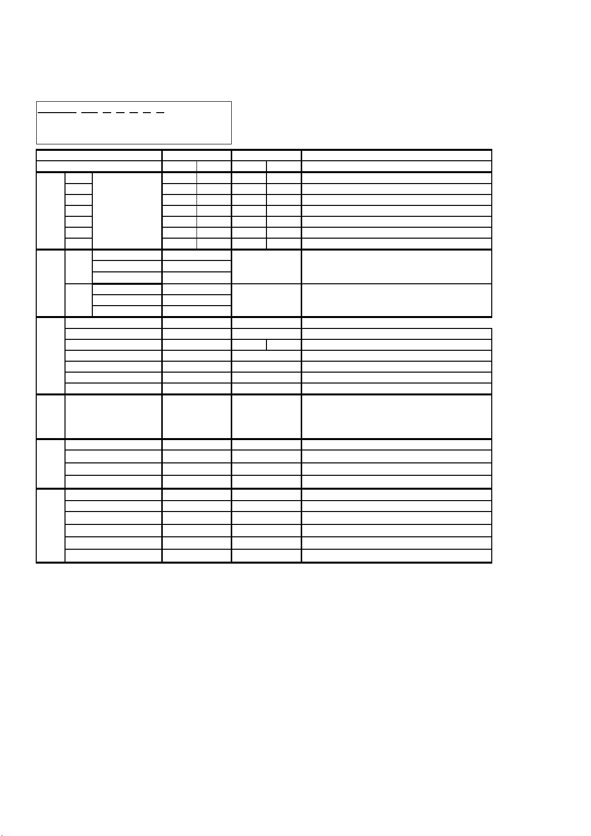
1.Notes on Application
Check Item
Using SGD/SGDA/SGDB
Type Servo Amplifier
Notes
Usage condition in ∑ Usage of ∑-V
Using S-phase output of absolute
encoder
Using auto tuning function The same auto-tuning function as Σ is
Using speed bias function The speed bias function is not provided
S-phase output is not available in
SGDV. There are no alternatives.
not provided in SGDV. The tuneless
function is the alternative function.
Please use the advanced auto-tuning
function or moment of inertia
identification function of SigmaWin+
when you need to know the moment of
inertia ratio.
in SGDV. The positioning time can be
shortened by using "Positioning setting
(model following control)" of the
advanced auto tuning function.
The main circuit power supply input
terminal and control power supply
input terminal are common in the
SGD/SGDA series
Using SGD(A)-S (speed・torque
control type)
Using SGD(A)-P (position
control type)
The main circuit power supply input
terminal and control power supply input
terminal are separated. Please
confirm the method of power activation.
There is no distinction between the
speed torque control type and
positional control type in SGDV. It is
possible to use either control type.
There is no distinction between the
speed torque control type and
positional control type in SGDV. It is
possible to use either control type.
2/47
Page 3

Using SGD-N or SGDB-AN
Please use MECHATROLINK-II
(MECHATROLINK communication
support type)
Using SGD-H (RS-422
communication support type) or
SGDB-AM (for multi-function
position control)
communication reference servo
amplifier (SGDV-1 type).
SGDV-1 type servo amplifier
corresponds to MECHATROLINK-II
communication (4Mbps).
Changing software of the host controller
may become necessary when using the
SGDV-1 type to replace
SGD-N type, SGDB-AN type,
because the corresponding
MECHATROLINK command is
different.
There is no option module with the
interface that can replace these. Please
consider the replacement with
MECHATROLINK-II communication
reference servo amplifier
(SGDV-1 type).
Using SGDB--P (duct
ventilation type)
The following functions and performances were improved by replacing ∑ with ∑- V.
・Added the small capacity medium inertia series (SGMJV type) to the motor lineup.
・Increased the peak speed of the motor from 4500rpm to 6000 rpm. (SGMJV type and SGMAV type)
・Improved the speed frequency response characteristic for performance.
SGDA / SGDB 250Hz ⇒ SGDV 1.6kHz (Load inertia=Rotor inertia of motor)
・Supports pulse train command input frequency of 4Mpps.
SIGN+PULSE and CW/CCW are 4Mpps. The A/B-phase 2-phase pulse train becomes 4Mpps at 1x2,
2Mpps at 2x2, and 1Mpps at 4x2.
However, it is 200kpps when connecting with open collector output.
・RoHS compliant as standard product.
・Safety standard (Safety Stop-0) embedded in standard products.
Please inquire to the factory. Although
there is a model that corresponds to the
duct ventilation type but the capacity is
limited and the installation size is
different.
・PC connection changed from RS-232C communication to USB.
3/47
Page 4

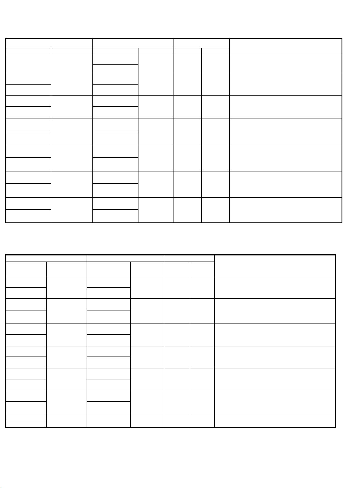
1-1.Check List when replacing ∑ with ∑-Ⅴ
Category Item Where to check Checked
Motor
Main Body
Voltage <Correspondence of AC100V specification>
<Confirmation of main body installation dimension/position>
・Please confirm installation dimensions of the motor in-use and
machine in-use.
Inside low diameter
Mounting hole pitch
Mounting hole diameter
Axis diameter
Axis shape (straight, key, center tap, and taper)
< Confirmation of special specification >
・Please confirm whether the motor you are using now is a special
type.
Please confirm the specification with the delivery specifications if
you are using a special type.
・Selected the both servo motor and servo amplifier which were for
100V when using the AC100V power supply in ∑-I. However, only
AC200V motor is available in the ∑-V. Select the proper servo
Servo
Amplifier
Hardware
amplifier when using AC100V power supply.
Cable <Confirmation of wiring direction>
・Please confirm how to wire, and also confirm that the machine has no
interference.
< Confirmation of main body mounting position >
・Please confirm the size (W・H・D) and the mounting hole position of
the servo amplifier in-use.
< Confirmation of special specification >
・Please confirm whether the servo amplifier in-use does not have your
own NP, and product shape, and also confirm that any special
processes etc. are not done by referring the delivery specification.
Main
Circuit
< Confirmation of wiring >
・Changed to the connector connection from the terminal block for
models of 1.5kW or less.
The main circuit connector, terminal block position, terminal marking
and order are different between the servo amplifier in-use and the
replacement servo amplifier.
Main Body
Please consider the substitution of extension of wiring when there is
not enough room in wiring.
4/47
Page 5

<Regenerative process>
・Regenerative processing unit (JUSP-RG08/JUSP-RG08C) is used
when regeneration processing is necessary in SGD/SGDA. In the
SGDV, the regeneration processing is possible by connecting the
regenerative resistor between the terminal B1 and B2.
<AC100V specification>
・Corresponds with the voltage specification "F" (Input 100V, Output
200V) servo amplifier. The servo motors are AC200V.
<Single phase AC200V specification>
・Three-phase circuit AC200V is standard in the ∑-V series servo
amplifier.
Change the parameter "Function selection switch B" when using
single-phase power supply. (Pn00B.2=1)
Connect to terminal L1 and L2 when using the single-phase power
supply.
Please note that the torque-speed characteristic is different from the
three-phase circuit power supply specifications.
Also please note that the size of the1.5kW single-phase AC200V
servo amplifier (SGDV-120AA008000) is the same as the 3kW
three-phase AC200V amplifier (SGDV-200AA).
<DC power supply input>
・Change the parameter "Function selection switch 1" when using
Servo
amplifier
software
DC power supply input. (Pn001.2=1)
Note) Connect the main circuit DC power supply only after changing
the parameter.
Control
circuit
Software <Confirmation of special software existence>
Constant <Confirmation of user constant>
Peripherals <Confirmation of the digital operator>
<Confirmation of wiring>
・The control circuit power supply input terminal is separated in the
SGDV type when it is replaced from the SGD type and SGDA type.
・ Confirm whether the software of the servo amplifier in-use is
standard software from the version number. Contact Yaskawa with
the version number if you are not sure the software is standard or
not.
・Confirm the user constant of the servo amplifier in-use.
SigmaWin + has a function to convert from the user constant of ∑
into the parameter of ∑- V.
・The digital operators for ∑ and ∑-V are different. Please purchase a
new digital operator if needed.
5/47
Page 6

<Confirmation of PC connection cable>
・The PC connection cables for ∑ and ∑-V are different.
Please purchase a new cable when using SigmaWin+.
Others In the Σ series, the stopping method is DB stop or free-run stop when
an alarm is detected. On the other hand, factory setting for G2 is 0
speed stop in Σ-V series. It is possible to change to the DB stop or
free-run stop when the parameter Pn00B.1=0 is set to1. The user
constant conversion function of SigmaWin + is not able to convert this.
6/47
Page 7
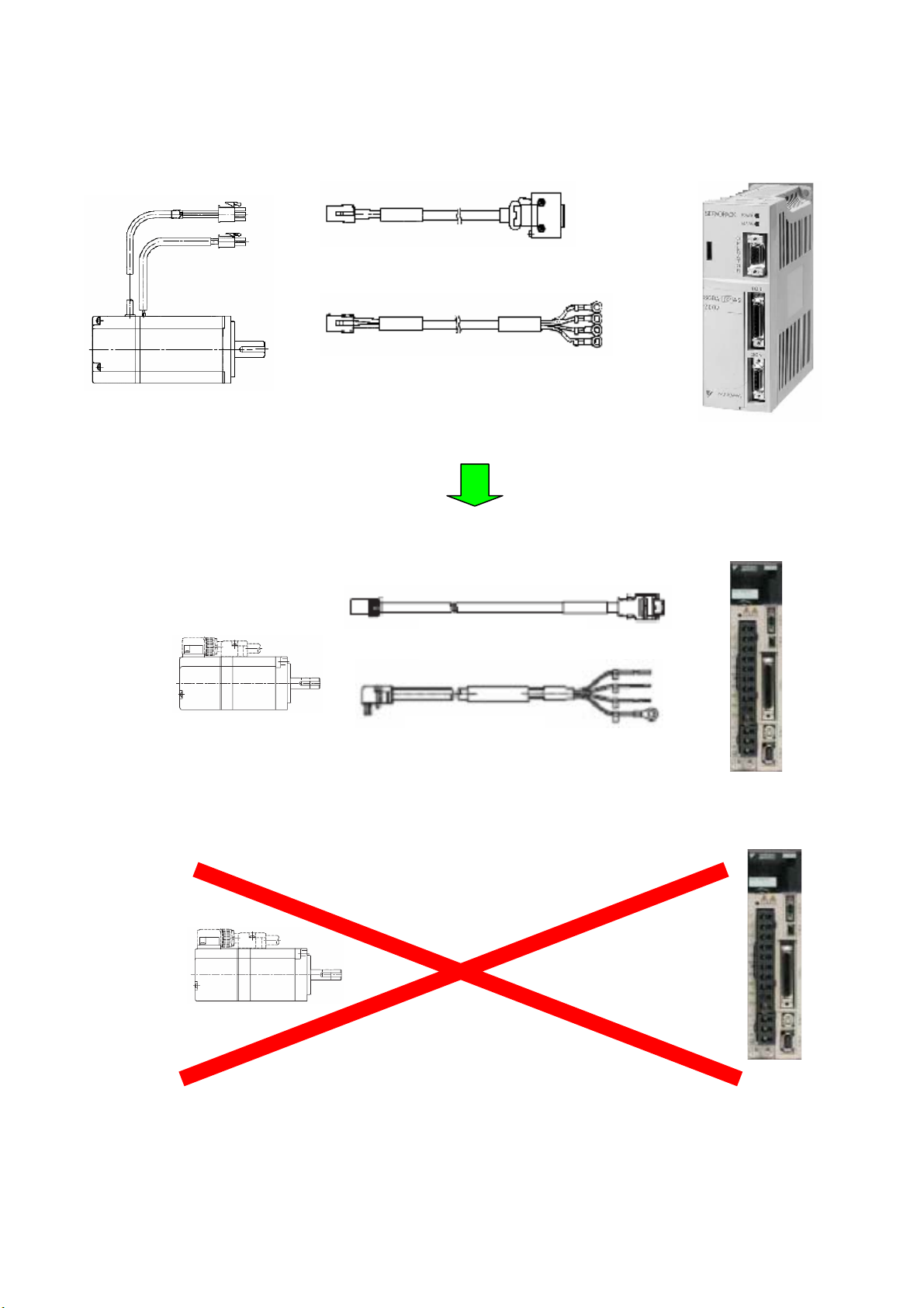
1-2.Concept of Replacement
When replacing ∑ series servo motor/servo amplifier with ∑-V series, the following methods are available.
Encoder Cable
Motor Cable
●Case 1
Replacing all the motors, servo amplifier, and cables with ∑-V series.
●Case 2
Only the motor or amplifier cannot be replaced by itself and the existing cable of ∑ series cannot be used as
is.
Encoder Cable
Motor Cable
7/47
Page 8
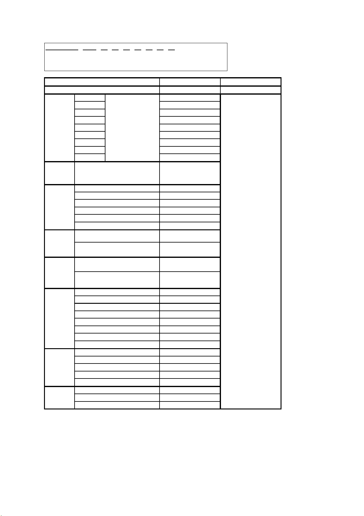
1-3. Replacement List
V
Replacing SGM with SGMJ
Type in-use of ∑ series Replacing type ∑-V series Replacing Method
Servo Amplifier Servo Motor Servo Amplifier Servo Motor Case 1 Case 2
SGDA-A3AS
SGDA-A3AP
SGD-A3AN SGDV-R70A11A
SGDA-A3BS
SGDA-A3BP
SGD-A3BN SGDV- R70F11A
SGDA-A5AS
SGDA-A5AP
SGD-A5AN SGDV-R70A11A
SGDA-A5BS
SGDA-A5BP
SGD-A5BN SGDV- R70F11A
SGDA-01AS
SGDA-01AP
SGD-01AN SGDV-R90A11A
SGDA-01BS
SGDA-01BP
SGD-01BN SGDV- R90F11A
SGDA-02AS
SGDA-02AP
SGD-02AN
SGDB-02AM
SGDA-02BS
SGDA-02BP
SGD-02BN SGDV-2R1F11A
SGDA-03BS
SGDA-03BP
SGD-03BN SGDV-2R8F11A
SGDA-04AS
SGDA-04AP
SGD-04AN
SGDB-05AM
SGDA-08AS
SGDA-08AP
SGD-08AN
SGDB-10AM
SGM-A3A
SGM-A3B
SGM-A5A
SGM-A5B
SGM-01A
SGM-01B
SGM-02A
SGM-02B
SGM-03B
SGM-04A
SGM-08A
SGDV-R70A01A
SGDV-R70F01A
SGDV-R70A01A
SGDV-R70F01A
SGDV-R90A01A
SGDV-R90F01A
SGDV-1R6A01A
SGDV-1R6A11A
SGDV-2R1F01A
SGDV-2R8F01A
SGDV-2R8A01A
SGDV-2R8A11A
SGDV-5R5A01A
SGDV-5R5A11A
SGMJV-A5A Applicable
SGMJV-A5A Applicable
SGMJV-01A Applicable
SGMJV-02A Applicable
SGMJV-04A Applicable
SGMJV-04A Applicable N/A -
SG0MJV-08 Applicable
N/A
N/A
N/A -
N/A
N/A
N/A
Note
30W version is not
available. Use 50W .
Axis diameter changes
to φ8 from φ6
Axis diameter changes
to φ8 from φ6
-
300W version is not
available. Use 400W .
Axis diameter changes
to φ19 from φ16
8/47
Page 9
Replacing SGM with SGMAV
Type in-use of ∑ series Replacing type ∑-V series Replacing Method
Servo Amplifier Servo Motor Servo Amplifier Servo Motor Case 1 Case 2
SGDA-A3AS
SGDA-A3AP
SGD-A3AN SGDV-R70A11A
SGDA-A3BS
SGDA-A3BP
SGD-A3BN SGDV- R70F11A
SGDA-A5AS
SGDA-A5AP
SGD-A5AN SGDV-R70A11A
SGDA-A5BS
SGDA-A5BP
SGD-A5BN SGDV- R70F11A
SGM-A3A
SGM-A3B
SGM-A5A
SGM-A5B
SGDV-R70A01A
SGDV-R70F01A
SGDV-R70A01A
SGDV-R70F01A
SGMAV-A5A Applicable
SGMAV-A5A Applicable
N/A
N/A
Note
30W version is not
available. Use 50W .
Axis diameter changes
to φ8 from φ6
Axis diameter changes
to φ8 from φ6
SGDA-01AS
SGDA-01AP
SGD-01AN SGDV-R90A11A
SGDA-01BS
SGDA-01BP
SGD-01BN SGDV- R90F11A
SGDA-02AS
SGDA-02AP
SGD-02AN
SGDB-02AM
SGDA-02BS
SGDA-02BP
SGD-02BN SGDV-2R1F11A
SGDA-03BS
SGDA-03BP
SGD-03BN SGDV-2R8F11A
SGDA-04AS
SGDA-04AP
SGD-04AN
SGDB-05AM
SGDA-08AS
SGDA-08AP
SGD-08AN
SGDB-10AM
SGM-01A
SGM-01B
SGM-02A
SGM-02B
SGM-03B
SGM-04A
SGM-08A
SGDV-R90A01A
SGDV-R90F01A
SGDV-1R6A01A
SGDV-1R6A11A
SGDV-2R1F01A
SGDV-2R8F01A
SGDV-2R8A01A
SGDV-2R8A11A
SGDV-5R5A01A
SGDV-5R5A11A
SGMAV-01A Applicable
SGMAV-02A Applicable
SGMAV-04A Applicable
SGMAV-04A Applicable N/A -
SGMAV-08A Applicable
N/A -
N/A
N/A
N/A
300W version is not
available. Use 400W .
Axis diameter changes
to φ19 from φ16
-
9/47
Page 10
p
Replacing SGMP with SGMJV or SGMPS
Type in-use of ∑ series Replacing type ∑-V series Replacing Method
Servo
lifier
Am
SGDA-01AS
SGDA-01AP
SGD-01AN SGDV-R90A11A
SGDA-01BS
SGDA-01BP
SGD-01BN SGDV- R90F11A
SGDA-02AS
SGDA-02AP
SGD-02AN
SGDB-02AM
SGDA-02BS
SGDA-02BP
SGD-02BN SGDV-2R1F11A
SGDA-03BS
SGDA-03BP
SGD-03BN SGDV-2R8F11A
SGDA-04AS
SGDA-04AP
SGDB-05ADP
SGD-04AN
SGDB-05AN
SGDB-05AM
SGDA-08AS
SGDA-08AP
SGDB10ADP
SGD-08AN
SGDB-10AN
SGDB-10AM
SGDB-15ADP SGDV-120A01A
SGDB-15AN
SGDB-15AM
Servo
Motor
SGMP-01A
SGMP-01B
SGMP-02A
SGMP-02B
SGMP-03B
SGMP-04A
SGMP-08A
SGMP-15A SGMPS-15A Available N/A
Servo Amplifier Servo Motor Case 1 Case 2
SGDV-R90A01A
SGMJV-01A
SGDV-R90F01A
SGDV-1R6A01A
SGDV-1R6A11A
SGDV-2R1F01A
SGDV-2R8F01A
SGDV-2R8A01A
SGDV-2R8A11A
SGDV-5R5A01A
SGDV-5R5A11A
SGDV-120A11A
or
SGMPS-01A
SGMJV-02A
or
SGMPS-02A
SGMJV-04A
or
SGMPS-04A
SGMJV-04A
or
SGMPS-04A
SGMJV-08A
or
SGMPS-08A
Available
Available
Available
Available N/A
Available
N/A
N/A
N/A
N/A
Note
Flange angle changes to 40° from 60
replacing with SGMJV.
SGMJV encoder is either the incremental
encoder 20bit, incremental encoder 13bit or
absolute encoder 20bit.
Flange angle is 60° (no change)
replacing with SGMPS.
SGMPS encoder is either the incremental
encoder 17bit or absolute encoder 17bit.
Flange angle changes to 60° from 80°
replacing with SGMJV.
SGMJV encoder is either the incremental
encoder 20bit, incremental encoder 13bit or
absolute encoder 20bit.
Flange angle is 80° (no change)
replacing with SGMPS.
SGMPS encoder is either the incremental
encoder 17bit or absolute encoder 17bit.
300W version is not available. Use 400W.
Flange angle changes to 60° from 80° when
replacing with SGMJV.
SGMJV encoder is either the incremental
encoder 20bit, incremental encoder 13bit or
absolute encoder 20bit.
Flange angle is 80° (no change)
replacing with SGMPS.
SGMPS encoder is either the incremental
encoder 17bit or absolute encoder 17bit.
Flange angle changes to 60° from 80°
replacing with SGMJV.
SGMJV encoder is either the incremental
encoder 20bit, incremental encoder 13bit or
absolute encoder 20bit.
Flange angle is 80° (no change)
replacing with SGMPS.
SGMPS encoder is either the incremental
encoder 17bit or absolute encoder 17bit.
Flange angle changes to 80° from 120° and
shaft diameter changes to ∅19 from ∅16
when replacing with SGMJV.
SGMJV encoder is either the incremental
encoder 20bit, incremental encoder 13bit or
absolute encoder 20bit.
Flange angle is 80° (no change) and shaft
diameter is ∅16 (no change) when replacing
with SGMPS.
SGMPS encoder is either the incremental
encoder 17bit or absolute encoder 17bit.
° when
when
when
when
when
when
when
10/47
Page 11
Replacing SGMG (1500min-1) with SGMGV
Fl
180⇒130(mm)
p
SGDV
SGDV
SGDV
(
Type in-use of ∑ series Replacing type ∑-V series Replacing Method
Servo Amplifier Servo Motor Servo Amplifier Servo Motor Case 1 Case 2
- - SGMGV-03A N/A N/A
SGDB-05ADG SGDV-3R8A01A
SGMG-05AA
SGDB-05AN SGDV-3R8A11A
SGDB-10ADG SGDV-7R6A01A
SGMG-09AA
SGDB-10AN SGDV-7R6A11A
SGDB-15ADG SGDV-120A01A
SGMG-13AA
SGDB-15AN SGDV-120A11A
SGDB-20ADG SGDV-180A01A
SGMG-20AA
SGDB-20AN SGDV-180A11A
SGDB-30ADG SGDV-330A01A
SGMG-30AA
SGDB-30AN SGDV-330A11A
SGDB-44ADG SGDV-330A01A
SGMG-44AA
SGDB-44AN SGDV-330A11A
SGDV-3R8A01A
SGDV-3R8A11A
SGMGV-05A Available N/A
SGMGV-09A Available N/A
SGMGV-13A Available N/A
SGMGV-20A Available N/A
SGMGV-30A Available N/A -
SGMGV-44A Available N/A
Note
Flange angle: 90mm
Shaft diameter: ∅14mm
Flange angle: 130 ⇒ 90(mm)
Shaft diameter: ∅19⇒ ∅16(mm)
Rotar inertia moment: 7.24⇒ 3.33(x10-
-
Rotar inertia moment: 20.5⇒ 19.9(x10-
4kg・m2)
ange angle:
Shaft diameter: ∅35⇒ ∅24(mm)
Rotar inertia moment: 31.7⇒ 26.0(x10-
・
-
Replacing SGMG (1000min-1) with SGMGV
Capacity of the servo motor SGMGV and servo amplifier go up
Type in-use of ∑ series Replacing type ∑-V series Replacing
Servo
lifier
Am
SGDB-03ADM
SGDB-05AN
SGDB-07ADM
SGDB-10AN
SGDB-10ADM SGDV-120A01A
SGDB-10AN SGDV-120A11A
SGDB-15ADM SGDV-180A01A
SGDB-15AN SGDV-180A11A
SGDB-20ADM SGDV-330A01A
SGDB-20AN SGDV-330A11A
SGDB-30ADM SGDV-330A01A
SGDB-30AN SGDV-330A11A
SGDB-44ADM
SGDB-44AN
Servo Motor
SGMG-03AΒ
SGMG-06AΒ
SGMG-09AΒ
SGMG-12AΒ
SGMG-20AΒ
SGMG-30A
SGMG-44AΒ
Β
Servo
Amplifier
-
-
-
SGDV7R6A11A
---
Servo
Motor
SGMGV-
05A
SGMGV-
09A
SGMGV-
13A
SGMGV-
20A
SGMGV-
30A
SGMGV-
44A
Case 1 Case 2
Available N/A
Available N/A
Available N/A
Available N/A
Available N/A
Available N/A
Note
Flange angle: 130 ⇒ 90(mm)
Shaft diameter: ∅19⇒ ∅16(mm)
Rotar inertia moment: 7.24⇒ 3.33(x10-
Rated torque: 5.68⇒ 5.39(N・m)
Peak torque: 14.1⇒ 13.8(N・m)
Rotar inertial moment: 20.5⇒ 19.9(x10-
4kg・m2)
Rated torque: 8.62⇒ 8.34(N・m)
Flange angle: 180⇒ 130(mm)
Shaft diameter: ∅35⇒ ∅24(mm)
Rotar inertia moment: 31.7⇒ 26.0
Rated torque: 19.1⇒ 18.6(N
-
-
x10-
・m)
11/47
Page 12
2. Motor
g
p
2-1. Type Comparison Table
・Comparison Table of SGM, SGMP and SGMAV, SGMJV (w/o reduction gears)
SGMJV- □□ □ □ □ □ □
Type Name ① ② ③ ④ ⑤ ⑥
Series Name
Servo Motor Type
30 A3 - - - 50W setting (30W setting is not available)
50 A5 - A5 A5 100 01010101 -
Capacity
①
Voltabe
Spec.
②
Detector
③
Design
Order
④
Shaft-
end
Spec.
⑤
Option
⑥
※ 100V in
W
200 02020202 300 03 03 - - 400W settin
400 04040404 750 08080808 -
Standard
100V
UL certified
CE certified
Standard
200V
UL certified
CE certified
2048p/r incremental encoder
8192p/r incremental encoder
13bit serial incremental encode
20bit serial incremental encode
12bit absolute encoder
15bit absolute encoder
20bit serial absolute encoder
Standard
w/ straight key
w/ straight key tap
w/o straight key w/tap
90V brake 24V brake (90V brake setting is not available)
24V brake Oil seal S
90V brake, Oil seal
24V brake, Oil seal
ut type only for 300W of SGM and SGMP
∑
SGM- SGMP- SGMAV- SGMJV-
B
L
W
A
U
V
3
2
-
W
S
-
1
2w/o straight key
4
6
8
-No option
B
C
D
E
∑-Ⅴ
-
A
-
-
-A D
-
3
A
2
6
8
1
C
S
-
E
Corresponds by combining the Servo amplifier 100V power
supply spec. "F" and motor for 200V
0bit serial incremental encoder (13bit is selectable for SGMJV
20bit serial incremental encoder
SGMJV Standard: Fully-closed, Self-cooling IP65 (excluding
SGMAV Standard: Fully-closed, Self-cooling IP55 (excluding
Set to "1" for no option instead of leaving as a blank
24V brake (90V brake setting is not available)
Supplement
(300W setting is not available)
-
20bit serial absolute encoder
20bit serial absolute encoder
-
shaft penetrated part)
shaft penetrated part)
-
Handle with straight key tap
-
-
-
-
12/47
Page 13

Comparison Table of SGMG and SGMGV
(
)
(
)
g
d
d
・
SGMGV- □□ □ □ □ □ □
Type Name ① ② ③ ④ ⑤ ⑥
w/o reduction gears
Capacity
①
Voltabe
Spec.
②
Detector
③
Design
Order
④
Shaft-
end
Spec.
Option
⑥
Series Name
Servo Motor Type SGMG- SGMGV-
0.3
0.45
0.6
0.85/0.9
1.2
1.3
1.8/2.0
2.9/3.0
4.4
4096p/r incremental encoder 6 8192p/r incremental encoder 2 13bit serial incremental enco
20bit serial incremental enco
12bit absolute encoder W 15bit absolute encoder S 20bit serial absolute encoder - 3
1500min-1 A A
1000min-1 B -
w/o straight key A 2
w/ straight key tap B 6
1/10 taper w/ key C,D -
No option - 1
DC90V brake B B
DC24V brake C C
DC90V brake, Oil seal F D
DC24V brake, Oil seal G E
Oil seal S S
kW
200
V
∑ ∑-Ⅴ
03 03
05 05
06 09
12 13 13
20 20
30 30
44 44
AA
-
-
09
-
D
Supplement
Rating 1000min-1model is not provided in
SGMGV. If you are using SGMG rating
1000min-1 model (SGMG-
the rating 1500min-1 model though the rated torque
and externals are different.
20bit serial incremental encoder
20bit serial incremental encoder
-
20bit serial absolute encoder
20bit serial absolute encoder
Standard: Fully-closed, Self-cooling IP67
excluding shaft penetrated part
Rating 1000min-1model is not provided please
use the ratin
-
No taper is available. Use straight key.
Set to "1" for no option instead of leaving as a
Use 24V Brake version
Use 24V Brake version
-
-
1500min-1 model.
B) please use
13/47
Page 14

・Comparison Table of SGM, SGMP and SGMAV, SGMJV (w/ reduction gears)
0
)
0
0
0
0
)
0
V
p
p
p
g
p
p
0
e
)
868
7
s
e
①④⑦⑧⑥③⑤
②
SGMJV- □□ □ □ □ □ □ □ □
Type Name
Cap ac i ty
①
Vol ta ge
Spec.
②
Det ec tor
③
Design
Or der
④
Ser ies Name ∑
Servo Motor Typ
3
5
10
20
30
40
750 08 08 08 08 -
100V
200V
2048p/r incremental encoder 3
8192p/r incremental encoder 2 13bit serial incremental encoder 20bit serial incremental encoder 12bit absolute encoder W -
20bit serial absolute encoder -
Standar d
W
Standard
UL certi fied
CE certi fi ed
Standard
UL certi fied
CE certi fi ed
SGM- SGMP- SGMAV- SGMJV-
A3 - - - 50W setting (30W setting is not avai lable
A5 - A5 A5 01 01 01 01 02 02 02 02 03 03 - - 400W setting (300W setting is not available
04 04 04 04 -
B
L
W
A
U
V
∑-Ⅴ
-
A
-
-A D
-15bit absolute encoder S
3
A1
Combining the Servo amplifier 100V power supply spec. "F"
0bit serial incremental encoder (13bis is sel ectable for SGMJ
20bit serial incremental encoder
20bit serial absolute encoder
20bit serial absolute encoder
SGMJV Standard: Fully-closed, Self-cooling IP55 (excluding
SGMAV Standard: Fully-closed, Self-cooling IP55 (excluding
Supplement
and motor for 200V
shaft penetrated part)
shaft
enetrated part)
-
-
-
Reduction
Gea r s
Spec.
⑤
Reduction
Rat io
⑥
Shaft-
end Spec.
⑦
Opt i on
⑧
Precision reduction gears
General -purpose reducti on gear
1/5
1/9
3/31
1/11
1/21
1/33
Flange mounting 0
w/o st ra ight key
w/ straight key
w/ straight key tap
w/ straight tap
No Opt ion
V br a k
9
24V brake -
J
1
2 ※
2 ※ 2 ※
3
4
0
2
4
B
C
HH
-
1
2 ※
B ※
C
2
6
1
-
C
●∑ series
SGM :Precision 1/5、1/9(50、100W)、1/11(except 50、100W)、1/21、1/33
General-Purpose 1/5、3/31、1/21、1/33
SGMP:Precision 1/5、1/11、1/21、1/33
General-Purpose 1/5、3/31、1/21、1/33
-
Use the precision reduction gears (general-purpose reduction
gears are not available)
-
onding to 50W
Cor r es
ond by 1/9 (only 50W) or 1/11
Cor res
Not corresponding to 50W
-
-
-
-
Handle with strai
Set to "1" for no o
24V brake (90V brake setting is not available
tion instead of leaving as a blank
ht key ta
-
-
14/47
Page 15
Comparison Table of SGMG and SGMGV
(
)
a
e
①⑥⑤④②⑧⑦
③
・
SGMGV- □□ □ □ □ □ □ □ □
Type Name
w/ reduction gears
Capacity
①
Voltabe
Spec.
②
Detector
③
Design
Order
④
Reduction
Gears
Spec.
⑤
Reduction
Ratio
⑥
Shaft-end
Spec.
⑦
Option
⑧
Series Name
Servo Motor Type SGMG- SGMGV-
0.3
0.45
0.6
0.85/0.9
1.2
1.3
1.8/2.0
2.9/3.0
4.4
4096p/r incremental encoder
8192p/r incremental encoder 2
20bit serial incremental encod
12bit absolute encoder W
15bit absolute encoder
20bit serial absolute encoder -
1500min-1 A
1000min-1 B
Precision reduction gears L
General-purpose reduction ge
Flange mounting (w/o shaft) w/o straight key w/ straight key K
w/ straight key tap
w/ straight tap No option DC90V brake
DC24V brake C
kW
V
200
1/5 1
1/6 A
1/9 2
1/11 B
1/20
1/21 C
1/29 7
1/45 8
∑∑-Ⅴ
03
05
06
09
12
13
20
30
44
A
6
-
S
Quotes in each case
S,T
5
R
B
15/47
Page 16

2-2. Characteristic
(Comparison between SGM, SGMP and SGMJV, SGMAV)
Motor Characteristic
∑ ∑-Ⅴ
Servo Motor Servo Motor
サーボモータ サーボモータ ∑ ∑-Ⅴ ∑ ∑-Ⅴ ∑ ∑-Ⅴ
SGM-A3A SGMJV-A5A 0.021 0.0414 0.095 0.159 0.29 0.557
SGM-A5A SGMJV-A5A 0.026 0.0414 0.159 0.159 0.48 0.557
SGM-01A SGMJV-01A 0.040 0.0665 0.318 0.318 0.96 1.11
SGM-02A SGMJV-02A 0.123 0.259 0.637 0.637 1.91 2.23
SGM-04A SGMJV-04A 0.191 0.442 1.27 1.27 3.82 4.46
SGM-08A SGMJV-08A 0.671 1.57 2.39 2.39 7.1 8.36
SGM-A3A SGMAV-A5A 0.021 0.0242 0.095 0.159 0.29 0.477
SGM-A5A SGMAV-A5A 0.026 0.0242 0.159 0.159 0.48 0.477
SGM-01A SGMAV-01A 0.040 0.038 0.318 0.318 0.96 0.955
SGM-02A SGMAV-02A 0.123 0.116 0.637 0.637 1.91 1.91
SGM-04A SGMAV-04A 0.191 0.19 1.27 1.27 3.82 3.82
SGM-08A SGMAV-08A 0.671 0.769 2.39 2.39 7.1 7.16
SGMP-01A SGMJV-01A 0.065 0.0665 0.318 0.318 0.96 1.11
SGMP-02A SGMJV-02A 0.209 0.259 0.637 0.637 1.91 2.23
SGMP-04A SGMJV-04A 0.347 0.442 1.27 1.27 3.82 4.46
SGMP-08A SGMJV-08A 2.11 1.57 2.39 2.39 7.1 8.36
Rotar Inertia Moment (x10-4kg・m2) Peak Torque (N・m) Rated Torque (N・m)
ロータ慣性 モーメント(x10
-4
kg・m2)
モータ特性
定格トルク(N・m) 瞬時最大トルク(N・m)
100%
80%
60%
40%
20%
Load Ratio of SGM [Rated Ratio]
SGMAV
SGMJV
0%
0 5 10 15 20 25 30
Load Inertia Moment Ratio [SGMAV ratio]
100%
80%
60%
Please refer to the graph on the left
to replace the SGM type with the types
of SGMJV or SGMAV.
Replace with the SGMAV type when
the ratio of load inertia moment and
rotor inertia moment is five times or
less, or the load ratio is 60% or more.
Replace with the SGMJV type as for
the rest of that.
【 Reference 】
The graph on the left shows the load
ratio when replacing the SGM type
which is used by 70% with the types of
40%
SGM-02
Effective Torque [Rated Ratio %]
20%
0%
0倍 5倍 10倍 15倍 20倍 25倍 30倍
Load Inertia Moment [Jm Ratio]
SGMAV-02
SGMJV-02
SGMJV and SGMAV.
The load ratio increases though the
control is steady because the rotor
inertia moment of SGMJV type is large.
16/47
Page 17

(Comparison between SGMG and SGMGV)
∑
(Rating 1500min-1)
(定格1500min-1)
Servo Motor
サーボモータ サーボモータ ∑ ∑-Ⅴ ∑ ∑-Ⅴ ∑ ∑-Ⅴ
SGMG-05A□A SGMGV-05A 7.24 3.33 2.84 2.86 8.92 8.92
SGMG-09A□A SGMGV-09A 13.9 13.9 5.39 5.39 13.8 13.8
SGMG-13A□A SGMGV-13A 20.5 19.9 8.34 8.34 23.3 23.3
SGMG-20A□A SGMGV-20A 31.7 26.0 11.5 11.5 28.7 28.7
SGMG-30A□A SGMGV-30A 46.0 46.0 18.6 18.6 45.1 45.1
SGMG-44A□A SGMGV-44A 67.5 67.5 28.4 28.4 71.1 71.1
The capacity of the servo motor SGMGV and servo amplifier SGDV goes up because of the
SGMG(定格1000min-1)からSGMGVへの置換えでは、定格トルクの違いにより、
rated torque differences when replacing
サーボモータSGMGVとサーボパックSGDVの容量がアップしますのでご注意ください。
∑
(定格1000min-1)
(Rating 1000min-1)
Servo Motor Servo Motor
サーボモータ サーボモータ ∑ ∑-Ⅴ ∑ ∑-Ⅴ ∑ ∑-Ⅴ
SGMG-03A□B
SGMG-06A□B
SGMG-09A□B
SGMG-12A□B
SGMG-20A□B
SGMG-30A□B
SGMG-44A□B SGMGV-44A 89.0 67.5 41.9 28.4 107.0 71.1
∑-Ⅴ
Servo Motor
Rotor Inertia Moment (x10-4kg・m2)
ロータ慣性モーメント(x10
SGMG (Rating 1000min-1) with SGMGV.
∑-Ⅴ
SGMGV-03A 2.48 1.96 5.88
SGMGV-05A 3.33 2.86 8.92
SGMGV-05A 3.33 2.86 8.92
SGMGV-09A 13.9 5.39 13.8
SGMGV-09A 13.9 5.39 13.8
SGMGV-13A 19.9 8.34 23.3
SGMGV-13A 19.9 8.34 23.3
SGMGV-20A 26.0 11.5 28.7
SGMGV-20A 26.0 11.5 28.7
SGMGV-30A 46.0 18.6 45.1
SGMGV-30A 46.0 18.6 45.1
SGMGV-44A 67.5 28.4 71.1
ロータ慣性モーメント(x10
7.24 2.84
13.9
20.5 8.62
31.7 11.5
46.0
67.5 28.4
Motor Characteristic
-4
kg・m2)
Motor Characteristic
-4
kg・m2)
モータ特性
Rated Torque (N・m)
定格トルク(N・m) 瞬時最大トルク(N・m)
モータ特性
定格トルク(N・m) 瞬時最大トルク(N・m)
5.68
19.1
Peak Torque (N・m)
Peak Torque (N・m) Rotor Inertia Moment (x10-4kg・m2) Rated Torque (N・m)
7.17
14.1
19.3
28.0
44.0
63.7
17/47
Page 18

2-3. Mounting Dimensions
L
e
e
e
e
(1) Without Reduction Gears (Standard)
Hatching-displayed the part where size is different between the ∑ motor and ∑-V motor.
LL LC
S
Reductio
n Gears
No
Redution
Gears
Motor
Capacity
Brake
[W] LC LL S LC LL S LC L
N/A 69.5
30
Available 101
N/A 77 70.5 69
50
Available 108.5 115.5 114
100 8
200
400
750 80 16
N/A 94.5 82.5 82.5
Available 135 127.5 127.5
N/A 96.5 80 80
Available 136 120 120
N/A 124.5 98.5 98.5
Available 164 138.5 138.5
N/A 145 115 115
Available 189.5 160 160
∑ series
SGM
40 6
40
6
40
60 14
60 14
∑-Ⅴ series
SGMAV SGMJV
40 8
40 8
60 14
60 14
80 19
S
40 8
40 8
60 14
60 14
80 19
Reduction
Gears
No
Reduction
Gears
Motor
Capacity
[W] LC LL S LC LL S
100 60 8 40 8
200 80 14
400 80 14
Brake
N/A 57 82.5
Availabl
N/A 62 80
Availabl
N/A 82 98.5
Availabl
N/A 81.5 115
Availabl
∑series
SGMP
86 127.5
93.5 120
113.5 138.5
115 160
∑-Ⅴ series
SGMJV
60 14
60 14
80 19750 120 16
18/47
Page 19

Reduction
Gears
No
Reduction
Gears
Motor
Capacity
[kW] LC LL S LC LL S
0.45 130 19
0.85
1.3 130 22
1.8 180 24
2.9 180 35
4.4 180 35 180 35
Brake
N/A 13 8 139
Available 176 172
N/A 16 1 137
Available 199 173
N/A 18 5 153
Available 223 189
N/A 16 6 171
Available 217 207
N/A 19 2 160
Available 243 208
N/A 22 6 184
Available 277 232
130 19
180 35
∑ Series
SGMG(1500r/min)
130 16
130 19
130 22
180 35
Σ-Ⅴ Series
SGMGV
Reduction
Gears
No
Reduction
Gears
Motor
Capacity
[kW] LC LL S LC LL S
0.3 130 19
0.6 130 19 130 16
0.9 130 22 130
1.2 180 35 180 22
2.0 180 35 180
3.0 180 35 180
4.4 180 42 180
Brake
N/A 13 8 126
Available 176 159
N/A 16 1 139
Available 199 172
N/A 18 5 137
Available 223 173
N/A 16 6 153
Available 217 189
N/A 19 2 171
Available 243 207
N/A 22 6 160
Available 277 208
N/A 26 0 184
Available 311 232
∑ Series
SGMG(1000r/min)
130 14
Σ-Ⅴ Series
SGMGV
19
24
35
35
19/47
Page 20

●Shaft Key Size
W
W
e
e
e
e
e
e
e
e
e
e
Shaded area displayed the part where size is different between the ∑ motor and ∑-V motor.
Reduction
Gears
No
Reduction
Gears
QK
U
W
T
Motor
Capacity
Oil Seal
[W]QKUWTQKU
30
50
100
200
N/A
Availabl
N/A
Availabl
N/A
Availabl
N/A 20
Availabl
14 1.2 2 2
14 1.2 2
14 1.8 3 3
14
N/A 20
Availabl
750
N/A 30
Availabl
14
25
∑ Series
SGM
2
35
5
355
355
SGMAV SGMJV
14 1.8 3 3
14 1.8 3 3 14 1.8 3 3
14355
14
355400 14 3 5 5
22 3.5 6 6 622
∑-Ⅴ Series
TQKU
14 1.8 3
14 3 5 5
3.5 6
T
3
Reduction
Gears
No
Reduction
Gears
(2) With General-Purpose Reduction Gears
The customers need to prepare the general-purpose reduction gears by themselves or it might be necessary for
them to consider replacing with a precise decelerator because there is no general-purpose reduction gears in the
in the ∑-V .
Motor
N/A
Availabl
N/A
Availabl
N/A
Availabl
N/A
Availabl
Brake
14 1.8 3 3 14 1.8 3 3
16 3 5
16 3 5
22355
Capacity
[W] QK U W T QK U W T
100
200
400
750
∑ Series
SGMP
5
5
LL LC
14 35
14 3
22 3.5 6
∑-Ⅴ Series
SGMJV
55
5
6
S
20/47
Page 21

L
Reduction
Gears
General-
Purpose
30
50
Reduction
Gear
Brake
Ratio
1/5 60
1/10.3 60 14
1/21 60
1/33 60 14
1/5 60
1/10.3 70 16
1/21 70 16
1/33 70 16
1/5 70 16
1/10.3 70 16
1/21 90 20
1/33 90 20
1/5 90 20
1/10.3 90 20
1/21 105 25
1/33 105 25
1/5 90 20
1/10.3 105 25
1/21 120 32
1/33 120 32
1/5 105 25
1/10.3 120 32
1/21 145
1/33 145 40
N/A 101.5
Available 133.5
N/A 101.5
Available 133.5
N/A 116.5
Available 148.5
N/A 116.5
Available 148.5
N/A 109 110 108.5
Available 141 155 153.5
N/A 114 110 108.5
Available 146 155 153.5
N/A 131 119 117.5
Available 163 164 162.5
N/A 131 134.5 133
Available 163 179.5 178
N/A 131.5 122 122
Available 173 167 167
N/A 131.5 146.5 146.5
Available 173 191.5 191.5
N/A 153 146.5 146.5
Available 194 191.5 191.5
N/A 153 149 149
Available 194 194 194
N/A 138 144 144
Available 178.5 184 184
N/A 138 144 144
Available 178.5 184 184
N/A 165.5 151 151
Available 206 191 191
N/A 165.5 151 151
Available 206 191 191
N/A 166 162.5 162.5
Available 206.5 202.5 202.5
N/A 172.5 169.5 169.5
Available 213 209.5 209.5
N/A 200.5 169.5 169.5
Available 241 209.5 209.5
N/A 200.5 202.5 202.5
Available 241 242.5 242.5
N/A 193 193 193
Available 238.5 238 238
N/A 196 193 193
Available 241.5 238 238
N/A 223 219 219
Available 268.5 264 264
N/A 223 219 219
Available 268.5 264 264
Motor
Capacity
[W]LCL
100
200
400
750
∑ Series
SGM
SLCLLSLCLLS
14
14
14
120 40 120 40
40
120 40 120 40
120 40 120 40
∑-Ⅴ Series (precision reduction gears)
SGMAV SGMJV
40 10 40 10
40 10 40 10
40 10 40 10
60 16 60 16
40 10 40 10
60 16 60 16
60 16 60 16
90 25 90 25
60 16 60 16
60 16 60 16
90 25 90 25
90 25 90 25
60 16 60 16
90
25 90 25
90 25 90 25
90 25 90 25
90 25 90 25
21/47
Page 22

Reduction
Gears
General-
Purpose
Motor
Capacity
[W] LC LL S LC LL S LC LL S
100
200
400
750
Reduction
Gear Ratio
1/5 70 16
1/10.3 70 16
1/21 90 20
1/33 90 20
1/5 90 20
1/10.3 90 20
1/21 105
1/33 105 25
1/5 90 20
1/10.3 105 25
1/21 120 32
1/33 120 32
1/5 105 25
1/10.3 120 32
1/21 145 40
1/33 145 40
Brake
N/A 11 2 122 122
Available 141 167 167
N/A 11 2 146.5 146.5
Available 141 191.5 191.5
N/A 116.5 146.5 146.5
Available 145.5 191.5 191.5
N/A 116.5 149 149
Available 145.5 194 194
N/A 121.5 144 144
Available 153 184 184
N/A 121.5 144 144
Available 153 184 184
N/A 13 2 151 151
Available 163.5 191 191
N/A 13 2 151 151
Available 163.5 191 191
N/A 141.5 162.5 162.5
Available 173 202.5 202.5
N/A 15 2 169.5 169.5
Available 183.5 209.5 209.5
N/A 15 9 169.5 169.5
Available 190.5 209.5 209.5
N/A 15 9 202.5 202.5
Available 190.5 242.5 242.5
N/A 151.5 193 193
Available 188 238 238
N/A 158.5 193 193
Available 195.5 238 238
N/A 169.5 219 219
Available 206 264 264
N/A 169.5 219 219
Available 206 264 264
∑ Series
SGMP
25
∑-Ⅴ Series (precision reduction gears)
SGMAV SGMJV
40 10 40 10
60 16 60 16
60 16 60 16
90 25 90 25
60 16 60 16
60 16 60 16
90 25 90 25
90 25 90 25
60 16 60 16
90 25 90 25
90 25 90 25
120 40 120 40
90 25 90 25
90 25 90 25
120 40 120 40
120 40 120 40
22/47
Page 23

Reduction
Gears
General-
Purpose
Motor
Capacity
[kW] LC LL S LC LL S
0.45
0.85
1.3
1.8
2.9
4.4
Reduction
Gear Ratio
1/6 160
1/11 160 φ28h6
1/21 160
1/29 160 φ38h6
1/6 160
1/11 160 φ28h6
1/21 210 φ38h6
1/29 210 φ38h6
1/6 160 φ28h6
1/11 210 φ38h6
1/21 210 φ38h6
1/29 260 φ58h6
1/6
1/11
1/21
1/29
1/6 210 φ38h6
1/11 210 φ38h6
1/21 260 φ58h6
1/29 340 φ68h6
1/6 260 φ58h6
1/11
1/21 340 φ68h6
1/29 400 φ78h6
Brake
N/A 138
Available 190
N/A 138
Available 190
N/A 138
Available 190
N/A 138
Available 190
N/A 161
Available 213
N/A 161
Available 213
N/A 161
Available 213
N/A 161
Available 213
N/A 185
Available 237
N/A 185
Available 237
N/A 185
Available 237
N/A 185
Available 237
N/A 166
Available 231
N/A 166
Available 231
N/A 166
Available 231
N/A 166
Available 231
N/A 192
Available 257
N/A 192
Available 257
N/A 192
Available 257
N/A 192
Available 257
N/A 226
Available 291
N/A 226
Available 291
N/A 226
Available 291
N/A 226
Available 291
210 φ38h6
210
260
260 φ58h6
260 φ58h6
∑ Series
SGMG(1500r/min)
φ28h6
φ28h6
φ28h6
φ38h6
φ58h6
∑-Ⅴ Series (precision reduction
gears)
SGMGV
Quotes in Each Case
23/47
Page 24

Reduction
Gears
General-
Purpose
Motor
Capacity
[kW] LC LL S LC LL S
0.3
0.6
0.9
1.2
2.0
3.0
4.4
Reduction
Gear Ratio
1/6 160
1/11 160
1/21 160
1/29 160
1/6
1/11
1/21 210 φ38h6
1/29 210 φ38h6
1/6 160 φ28h6
1/11 160 φ28h6
1/21 210 φ38h6
1/29 210 φ38h6
1/6 210 φ38h6
1/11 210 φ38h6
1/21 260
1/29 260 φ58h6
1/6 210 φ38h6
1/11 210 φ38h6
1/29 340 φ60h6
1/6
1/11
1/21
1/29
1/6 260
1/11 260
1/21 400
Brake
N/A 138
Available 190
N/A 138
Available 190
N/A 138
Available 190
N/A 138
Available 190
N/A 161
Available 213
N/A 161
Available 213
N/A 161
Available 213
N/A 161
Available 213
N/A 185
Available 237
N/A 185
Available 237
N/A 185
Available 237
N/A 185
Available 237
N/A 166
Available 231
N/A 166
Available 231
N/A 166
Available 231
N/A 166
Available 231
N/A 192
Available 257
N/A 192
Available 257
N/A 192
Available 257
N/A 192
Available 257
N/A 226
Available 291
N/A 226
Available 291
N/A 226
Available 291
N/A 226
Available 291
N/A 260
Available 325
N/A 260
Available 325
N/A 260
Available 325
N/A 260
Available 325
160
160 φ28h6
260 φ58h61/21
260
260
340
400
4001/29
∑ Series
SGMG(1000r/min)
φ28h6
φ28h6
φ28h6
φ28h6
φ28h6
φ58h6
φ50h6
φ50h6
φ60h6
φ70h6
φ50h6
φ50h6
φ70h6
φ70h6
∑-Ⅴ Series (precision reduction
gears)
SGMGV
Quotes in each time
24/47
Page 25

(3)With Precision Reduction Gears
LL LC
S
25/47
Page 26

[
Reduction
Gears
Precision
Reduction
Gears
Motor
Capacity
100
200
400
750
Reduction
Gear Ratio
W] LC LL S LC LL S LC LL S
1/5
1/9
30
1/21
1/33
1/5
1/9
50
1/21
1/33
1/5
1/11
1/21
1/33
1/5
1/11
1/21
1/33
1/5
1/11
1/21
1/33
1/5
1/11
1/21
1/33
Brake
N/A 97.5
Available 129.5
N/A 97.5
Available 129.5
N/A 112.5
Available 144.5
N/A 112.5
Available 144.5
N/A 105 110 108.5
Available 137 155 153.5
N/A 106 110 108.5
Available 138 155 153.5
N/A 123 119 117.5
Available 155 164 162.5
N/A 123 134.5 133
Available 155 179.5 178
N/A 123.5 122 122
Available 164.5 167 167
N/A 140.5 146.5 146.5
Available 181.5 191.5 191.5
N/A 149.5 146.5 146.5
Available 190.5 191.5 191.5
N/A 149.5 149 149
Available 190.5 194 194
N/A 134.5 144 144
Available 175 184 184
N/A 151.5 144 144
Available 192 184 184
N/A 159.5 151 151
Available 200 191 191
N/A 159.5 151 151
Available 200 191 191
N/A 162.5 162.5 162.5
Available 203 202.5 202.5
N/A 187.5 169.5 169.5
Available 228 209.5 209.5
N/A 195.5 169.5 169.5
Available 236 209.5 209.5
N/A 195.5 202.5 202.5
Available 236 242.5 242.5
N/A 187 193 193
Available 232.5 238 238
N/A 216 193 193
Available 261.5 238 238
N/A 223 219 219
Available 268.5 264 264
N/A 223 219 219
Available 268.5 264 264
∑ Series
SGM
60 14
60 14
60
60 14
60
70
70 16
70
90 20
90 20
90 20
105 25 90 25
105 25 90 25
90 20
105 25 90 25
120 32
120 32 120 40
105 25
120 32
145 40
145 40
14
14 40 10
16
16
SGMAV SGMJV
40 10
60 16 16
60 16 60
90 25 90 25
60 16 60 16
60 1690 20
60 16
90 25
90
90 25
120 40
120 40 120
∑-Ⅴ Sereis
40 10
40 1040 10
40 10
60 1660 16
1070 16
25
40 1040
6070 16
60 16
90 25
90 25
60 16
90 25
90 25
120 40
90 25
90
120 40
16
25
40
26/47
Page 27

e
e
e
e
e
e
e
e
e
e
e
e
e
e
e
e
Reduction
Gears
Precision
Reduction
Gears
Motor
Capacity
[W] LC LL S LC LL S LC LL S
100
200
400
750
Reduction
Gear Ratio
1/5 70 16
1/11 70 16
1/21 90 20
1/33 90 20 90 25 90 25
1/5 90 20
1/11 90 20
1/21 105 25
1/33 105 25 90 25 90 25
1/5 90 20 60 16 60 16
1/11 105 25 90 25 90 25
1/21 120 32 90 25 90 25
1/33 120 32 120 40 120 40
1/5 105 25 90 25 90 25
1/11 120 32 90 25 90 25
1/21 145 40 120 40 120 40
1/33 145 40 120 40 120 40
Brake
N/A 104 122 122
Availabl
N/A 104 146.5 146.5
Availabl
N/A 113 146.5 146.5
Availabl
N/A 113 149 149
Availabl
N/A 118 144 144
Availabl
N/A 118 144 144
Availabl
N/A 126 151 151
Availabl
N/A 126 151 151
Availabl
N/A 138 162.5 162.5
Availabl
N/A 146 169.5 169.5
Availabl
N/A 154 169.5 169.5
Availabl
N/A 154 202.5 202.5
Availabl
N/A 145.5 193 193
Availabl
N/A 153.5 193 193
Availabl
N/A 169.5 219 219
Availabl
N/A 169.5 219 219
Availabl
∑ Series
SGMP
133 167 167
133 191.5 191.5
142 191.5 191.5
SGMAV SGMJV
40 10 40 10
60 16 60 16
60 16 60 16
∑-Ⅴ Series
142 194 194
149.5 184 184
149.5 184 184
157.5 191 191
60 16 60 16
60 16 60 16
90 25 90 25
157.5 191 191
169.5 202.5 202.5
177.5 209.5 209.5
185.5 209.5 209.5
185.5 242.5 242.5
182 238 238
187 238 238
203 264 264
203 264 264
27/47
Page 28

Reduction
Gears
Precision
Reduction
Gears
Motor
Capacity
[W] LC LL S LC LL S
0.45
0.85
1.3
1.8
2.9
4.4
Reduction
Gear Ratio
1/5 140
1/9
1/20 245
1/29 245 φ50h6
1/45
1/5 140
1/9
1/20 245 φ50h6
1/29 245 φ50h6
1/45
1/5 245 φ50h6
1/9
1/20 245 φ50h6
1/29
1/45
1/5
1/9
1/20
1/29
1/5 310 φ60h6
1/9 310 φ60h6
1/20
1/5 310
1/9 310 φ60h6
Brake
N/A 138
Available 190
N/A 138
Available 190
140 φ35h6
N/A 138
Available 190
N/A 138
Available 190
N/A 138
Available 190
245 φ50h6
N/A 161
Available 213
N/A 161
Available 213
140 φ35h6
N/A 161
Available 213
N/A 161
Available 213
N/A 161
Available 213
310
N/A 185
Available 237
N/A 185
Available 237
245 φ50h6
N/A 185
Available 237
N/A 185
Available 237
N/A 185
Available 237
N/A 166
Available 231
N/A 166
Available 231
N/A 166
Available 231
N/A 166
Available 231
310 φ60h6
310
245 φ50h6
245
310
310
N/A 192
Available 257
N/A 192
Available 257
N/A 192
Available 257
310 φ60h6
N/A 226
Available 291
N/A 226
Available 291
∑ Series
SGMG(1500r/min)
φ35h6
φ50h6
φ35h6
φ60h6
φ60h6
φ50h6
φ60h6
φ60h6
φ60h6
∑-Ⅴ Series
SGMGV
Quotes each time
28/47
Page 29

Reduction
Gears
Precision
Reduction
Gears
Motor
Capacity
[W] LC LL S LC LL S
0.45
1.3
1.8
2.9
4.4
Reduction
Gear Ratio
1/5 140
1/9 140
1/20
1/29 245
1/45
1/5 140 φ35h6
1/9 140 φ35h6
1/20 245 φ50h60.85
1/29 245 φ50h6
1/45 310 φ60h6
1/5 245 φ50h6
1/9 245 φ50h6
1/20 245 φ50h6
1/29 310 φ60h6
1/45 310 φ60h6
1/5 245 φ50h6
1/9 245 φ50h6
1/20 310 φ60h6
1/29 310 φ60h6
1/5 310 φ60h6
1/9 310 φ60h6
1/20 310
1/5 310 φ60h6
1/9 310 φ60h6
Brake
N/A 138
Available 190
N/A 138
Available 190
N/A 138
Available 190
245
N/A 138
Available 190
N/A 138
Available 190
245 φ50h6
N/A 161
Available 213
N/A 161
Available 213
N/A 161
Available 213
N/A 161
Available 213
N/A 161
Available 213
N/A 185
Available 237
N/A 185
Available 237
N/A 185
Available 237
N/A 185
Available 237
N/A 185
Available 237
N/A 166
Available 231
N/A 166
Available 231
N/A 166
Available 231
N/A 166
Available 231
N/A 192
Available 257
N/A 192
Available 257
N/A 192
Available 257
N/A 226
Available 291
N/A 226
Available 291
∑ Sereies
SGMG(1000r/min)
φ35h6
φ35h6
φ50h6
φ50h6
φ60h6
∑-Ⅴ Series
SGMGV
Quotes each time
29/47
Page 30

2-4. Notes at Machine Installation
Please cautious about the cable wiring as well as the size of the flange, spigot, and shaft at machine
installation. The pictures shown below are the part of the motor cable wiring of 40 and 60.
40
60
30/47
Page 31

3. Servo Amplifier
3-1. Type Comparison Table
1-3. Please refer to the replacement list
The servo amplifier type has been changed from the capacity value to output current value.
3-2. Terminal Table
(1) Main circuit terminal
Σ
SGDA type SGDB type
Terminal marking Terminal marking Terminal marking Function
RR
TS
T
UU
V
W
Rr
Tt
PP
NN
VV
WW
P,P1,B
∑-Ⅴ
SGDV type
L1
L2
L3
U
L1C
L2C
B1/(+)
B2
B3
(+)1
(+)2
(-)1
(-)2
B1/(+)
(-)
(-)2
・Single-phase power supply AC200V:
Main circuit power supply input terminal
Servomotor connection terminal
Control power supply input terminal (100V/200V type)
External regenerative resistor connection terminal
The connection method is different in Σ-Ⅴ
DC reactor conncetion terminal for power line
harmonics control
Main circuit forward side terminal
Main circuit reverse side terminal
It is possible to change to single phase power supply AC200V by the parameter (Factory setting is “3-phase
power supply”) however, the torque - rotational speed characteristic is different from the three-phase power
supply specification.
31/47
Page 32

(2) Control Circuit Terminal
e
e
(*3)
f
Σ-V Notes
1. Do not use the reserved terminal of "―"
2. Connect the shield line of the cable for I/O with the connector shell. It should be connected with frame
ground (FG) at the servo amplifier side connector.
3. The following input signals can change the parameter allocation
/DEC,P-OT,N-OT,EXT1, EXT2 ,EXT3
4. The signals of /COIN, /V-CMP, /TGON, /S-RDY, /CLT, /VLT, /BK, /WARN, /NEAR are able to allocate to
/SO1, /SO2, /SO3
Please refer to the Σ-V manual for details.
Comparison between SGDA-□□□S type [Analog voltage reference type] (speed & torque control
type) and SGDV type
Terminal No.
SGDA typ
GDV typ
Terminal Marking Function
36pin 50pin
19
35
2,4,6,10 1,2,6,10
54
7-
825
927
11 45
12 46
13 47
14 40
15 41
16 42
17 43
18 44
19 -
20 33
21 34
22 35
23 36
24 19
25 20
26 -
27 -
28 21
29 22
30 37
31 38
32 39
33 -
34 31
35 32
36 Shell
T-REF Torque reference input
V-REF Speed reference input
GND Ground
SEN SEN signal input
/BK+ Brake interlock output (*3)
/V-CMP+(./COIN+)
Speed match detection output (*2)
/TGON+ Rotation detection output (*2)
/P-CL Forward side external torque control input (*2)
/N-CL Reverse side external torque control input (*2)
+24VIN External power supply input
/S-ON Servo ON input (*2)
/P-CON P operation input (*2)
P-OT Forward drive prohibited input (*2)
N-OT Reverse drive prohibited input (*2)
/ALM-RST Alarm reset inupt (*2)
SG-PG Single ground for PG signal output
PAO PG frequence dividing output A-phase
/PAO
PBO PG frequence dividing output B-phase
/PBO
PCO PG frequence dividing output C-phase
/PCO
PSO S-phse signal output
/PSO
BAT(+) Battery(+)
BAT(-) Battery(-)
ALO1 Alarm code output
ALO2
ALO3
SG-AL Signal ground for alarm code output
ALM+ Servo alarm output
ALMFG Frame Ground
(*2): The sequence I/O is factory setting
The allocation change is possible by using the user parameter in ∑-V, but not in ∑ series
:Change the setting of one of three factory setting output signals by user parameter i
needed
32/47
Page 33

The number of CN1 input signal connector pins of ∑ series SGDA type and ∑-V series SGDV type are
different.
The CN2 encoder connector is not compatible.
The CN5 analogue monitor connector is compatible.
33/47
Page 34

Comparison between SGDA-□□□P type [pulse train reference type] (position control type) and
e
SGDV type
SGDA typeGDV typ
36pin 50pin
17
28
311
412
515
614
7-
825
927
10 1,2,6,10
11 45
12 46
13 47
14 40
15 41
16 42
17 43
18 44
19 -
20 33
21 34
22 35
23 36
24 19
25 20
26 -
27 -
28 21
29 22
30 37
31 38
32 39
33 -
34 31
35 32
36 Shell
Terminal Marking Function
PULS Reference pule input
/PULS
SIGN Reference symbol input
/SIGN
CLR Clear input
/CLR
/BK+ Brake interlock output (*3)
/V-CMP+(./COIN+)
/TGON+ Rotation detection output (*2)
GND Ground
/P-CL Forward side external torque control input (*2)
/N-CL Reverse side external control input (*2)
+24VIN External power supply input
/S-ON Servo ON input (*2)
/P-CON P operation input (*2)
P-OT Forward drove prohibited input (*2)
N-OT Reverse drive prohibited input (*2)
/ALM-RST Alarm reset input (*2)
SG-PG Single ground for PG signal output
PAO PG frequency dividing output A-phase
/PAO
PBO PG frequency dividing output B-phase
/PBO
PCO PG frequency dividing output C-phase
/PCO
PSO S-phase signal output
/PSO
BAT(+) Battery(+)
BAT(-) Battery(-)
ALO1 Alarm code output
ALO2
ALO3
SG-AL Signal ground for alarm code output
ALM+ Servo alarm output
ALMFG Frame ground
Speed match detection output (*2)
(*2): The sequence I/O is factory setting
The allocation change is possible by using the user parameter in ∑-V, but not in ∑ series
(*3):Change the setting of one of three factory setting output signals by user parameter
if needed
The number of CN1 input signal connector pins of ∑ series SGDA type and ∑-V series SGDV type are
different.
The CN2 encoder connector is not compatible.
The CN5 analogue monitor connector is compatible.
34/47
Page 35

Comparison between SGDB-□□□D type and SGDV type
e
Terminal No.
SGDB type
50pin 50pin
11
22
33
44
55
66
77
88/PULS
99
10 10
11 11
12 12
13 13
14 14
15 15
16 17 18 18
19 19
20 20
21 21
22 22
23 24 25 25
26 26
27 27
28 28
29 29
30 30
31 31
32 32
33 33
34 34
35 35
36 36
37 37
38 38
39 39
40 40
41 41
42 42
43 43
44 44
45 45
46 46
47 47
48 49 50 -
GDV typ
Terminal Marking Function
SG Signal Ground
SG Signal Ground
PL1 Battery for open collector reference
SEN SEN signal input
V-REF Speed reference input
SG Signal Ground
PULS Reference pulse input
Reference pulse input
T-REF Tordque reference input
SG Signal Ground
SIGN Reference code input
/SIGN Reference code input
PL2 Battery for open collector reference
/CLR Clear input
CLR Clear input
TRQ-M Torque monitor
VTG-M Speed monitor
PL3 Battery for open collector reference
PCO PG frequency dividing output C-phase
/PCO PG frequency dividing output C-phase
BAT /BAT(+) Battery (+)
BAT0 / BAT(-) Battery (-)
+12V Battery for analog refernce
-12V Battery for analog refernce
/V-CMP//COIN Speed match detection output
/V-CMP//COIN Speed match detection output
/TGON+ Rotating detection output
/TGON- Rotating detection output
/S-RDY+ Servo-ready output
/S-RDY- Servo-ready output
ALM+ Servo alarm output
ALM- Servo alarm output
PAO PG frequency dividing output A-phase
/PAO PG frequency dividing output A-phase
PBO PG frequency dividing output B-phase
/PBO PG frequency dividing output B-phase
ALO1 Alarm code output
ALO2 Alarm code output
ALO3 Alarm code output
/S-ON Servo ON inuput (*2)
/P-CON P operation input (*2)
P-OT Forward drive prohibit input (*2)
N-OT Reverse drive prohibit input (*2)
/ALMRST Alarm reset input
/P-CL Forward side external torque limit input
/N-CL Reverse side external torque limit input
+24 VIN External power supply input
PSO S-phase signal output
/PSO S-phase signal output
FG Frame Ground
(*2): The sequence I/O is factory setting
The allocation change is possible by using the user parameter in ∑-V, but not in ∑ series
(*3):Change the setting of one of three factory setting output signals by user parameter if
needed
35/47
Page 36

Comparison between SGDA-□□□N type [MECHATROLINK communication reference type] and
SGDV type
ΣΣ-Ⅴ
SGDA-
Terminal
No.
26pin 26pin
□□□
Terminal
Marking
N
SGDVTerminal
1/BK 1
2BK-SG 2
3ALM 3ALM+ Servo alarm outptu
4 ALM-SG 4 ALM- Servo alarm outptu
5― 5― ― Reserved terminal
6 +24VIN 6 +24VIN External power supply input
7P-OT 7
8N-OT 8
9/DEC 9
10 /EXT 10
―― 11
―― 12
― ― 13 /SI0 General purpose inut
14 BAT(+) 14 BAT(+) Battery(+) When using absolute encoder
15 BAT(-) 15 BAT(-) Battery(-) When using absolute encoder
― ― 16 SG Signal ground
―― 17PAO
― ― 18 /PAO
―― 19PBO
― ― 20 /PBO
―― 21PCO
― ― 22 /PCO
― ― 23 /SO2+ General purpose output
― ― 24 /SO2- General purpose output
― ― 25 /SO3+ General purpose output
― ― 26 /SO3- General purpose output
26FG ――Frame Ground
□□□□1□□
No.
Terminal
Marking
/BK(+)
(/SO1+)
/BK(-)
(/SO1-)
P-OT
(/SI1)
N-OT
(/SI2)
/DEC
(/SI3)
/EXT1
(/SI4)
/EXT2
(/SI5)
/EXT3
(/SI6)
Function
Brake interlock output
Brake interlock output
Forward drive prohibit input
Reverse drive prohibit input
Homing deceleration LS input
External latch signal 1 input
External latch signal 2 input
External latch signal 3 input
PG frequency dividing output A-phase
PG frequency dividing output B-phase
PG frequency dividing output C-phase
Remarks
Function is the same though the
terminal marking is different
Function is the same though the
terminal marking is different
There is just one external latch
signal in Σ
The connector is different though the number of CN1 I/O signal pins of the Σseries and Σ-V series are the same.
36/47
Page 37

Comparison between SGDB-□□□N type [MECHATROLINK communication reference type] and
―
∑
e
SGDV type
ΣΣ-Ⅴ
SGDB-
Terminal
No.
26pin 26pin
□□□
NSGDV-
Terminal
Marking
Terminal
1/BK 1
2 BK-SG 2
3 ALM 3 ALM+ Servo alarm output
4 ALM-SG 4 ALM- Servo alarm output
5― 5―
6 +24VIN 6 +24VIN External power supply output
7P-OT 7
8N-OT 8
9/DEC 9
10 /EXT 10
―― 11
―― 12
― ― 13 /SI0 General input
― ― 14 BAT(+) Battery(+) When using absolute encoder
― ― 15 BAT(-) Battery(-) When using absolute encoder
― ― 16 SG Signal Ground
―― 17PAO
― ― 18 /PAO
―― 19PBO
― ― 20 /PBO
―― 21PCO
― ― 22 /PCO
― ― 23 /SO2+ General purpose output
― ― 24 /SO2- General purpose output
― ― 25 /SO3+ General purpose output
― ― 26 /SO3- General purpose output
26 FG ― ― Frame Ground
□□□□1□□
No.
Terminal
Marking
/BK(+)
(/SO1+)
/BK(-)
(/SO1-)
P-OT
(/SI1)
N-OT
(/SI2)
/DEC
(/SI3)
/EXT1
(/SI4)
/EXT2
(/SI5)
/EXT3
(/SI6)
Function
Remarks
Brake interlock output
Brake interlock output
Funciton is the same though the terminal
marking is different
Funciton is the same though the terminal
marking is different
Reserved terminal
Forward drive prohibit input
Reverse drive prohibit input
Homing deceleration LS input
External latch signal 1 input There is just one external latch signal in
External latch signal 2 input
External latch signal 3 input
PG frequency dividing A-phase
PG frequency dividing B-phase
PG frequency dividing C-phase
The connector is different thought the number of CN1 I/O signal pins of the Σ series and Σ-Ⅴ series are the sam
37/47
Page 38

3-3. Installation Size
Σ-V series servo amplifier is not compatible with Σ series servo amplifier in the dimension and mounting
dimension. The position of the screw for the installation is different.
【AC200V, 200W or less】
2-M4 Tap
【AC100V, 200W or less and AC200V, 400W】
2-M4 Tap
38/47
Page 39

【AC100V, 400W and AC200V, 750W】
S-N4 Tap
【0.5kW~1.5kW】
4-M5 Mounting Hole
Vent
10 or more
Mounting Pitch
4-M4 Screw Hole
External
Mounting Pitch
10 or more
Mounting Pitch
39/47
Page 40

【2.0 kW, 3.0kW】
4-M5 Mounting Hole
Vent
4-M5 Screw Hole
10 or more
External
Mounting Pitch
10 or more
Mounting Pitch
【5.0kW】
4-M5 Screw Hole
External
4-M5 Tap Vent Hole
Mounting Pitch
Mounting Pitch
40/47
Page 41

3-4. Notes when Installing Control Board
Please note the difference of the electrical conduction state of frame ground when producing the
attachment to accommodate the difference of the installation hole size. An alarm may occur and the
machine may operate improperly because the amount of noise changes when the electrical conduction
state changes.
Servo Amplifier
The frame ground of the control
board and servo amplifier
conduct through the installation
screw.
Control Board Side
Attachment
Control Board Side
Conducting Part
Servo Amplifier
When painting and/or surface treatment is
given to the attachment for rust prevention,
electrical conduction between the attachment
and control board may be impossible.
41/47
Page 42

4. Cable and Peripherals
All the cables and peripherals of ∑ series are not compatible with Σ-V series’s so please confirm the
applicable products by referring to the catalog and manual, etc.
Please refer to the following comparison table for the type of the applicable products.
■ Connector for I/O Signal
■入出力信号用コネクタ
Analog・Pulse Train Reference Type
アナログ・パルス列指令形
名称
Name
コネクタ端子台変換ユニット JUSP-TA36P JUSP-TA50P JUSP-TA50PG-E
Connector Terminal Block Conversion Unit
片側ばら出しケーブル DE9404859 DE9406969-1 JZSP-CSI01-1-E
One-sided individual pull out cable
Connector Kit (for CN1)
コネクタキット(CN1用) DP9420007 DE9406970 JZSP-CSI9-1-E
Type
形式
(for SGDA type)
Σ (SGDA形用) Σ (SGDB形用) Σ-Ⅴ (SGDV形用)
(for SGDB type) (for SGDV type)
JUSP-TA50PG-1-E
JUSP-TA50PG-2-E
DE9406969-2 JZSP-CSI01-2-E
DE9406969-3 JZSP-CSI01-3-E
■ MECHATROLINK Communication Reference Type
MECHATROLINK通信指令形
名称 形式
Name
Connector Terminal Block Conversion Unit
コネクタ端子台変換ユニット JUSP-TA26P JUSP-TA26P -
Connector Kit (for CN1)
コネクタキット(CN1用) DE9411354 DE9411354 JZSP-CSI9-2-E
Σ(SGD-□□□N) Σ(SGDB-□□□N) Σ-Ⅴ(SGDV)
Type
■ Analog Monitor
■アナログモニタ
名称 形式
Name
Cable for Analog Monitor
アナログモニタ用ケーブル DE94094559 DE94094559 JZSP-CA01-E
Type
Σ(SGDA) Σ(SGDB) Σ-Ⅴ(SGDV)
■ PC Connection Cable
■パソコン接続ケーブル
名称 形式
Name
パソコン接続ケーブル DE9405258 DE9405258 JZSP-CVS06-02-E
PC Connection Cable
■ MECHATROLINK Communication Cable
■MECHATROLINK通信ケーブル
名称 形式
Name
両端コネクタ付きケーブル JEPMC-W6002-A5-E
Cable with both-ended Connector
Terminator
ターミネータ - - JEPMC-W6022-E
Type
Σ(SGDA) Σ(SGDB) Σ-Ⅴ(SGDV)
DE9408564 DE9408564 (USB接続)
DE9408565 DE9408565
(USB connection)
Type
Σ(SGDA) Σ(SGDB) Σ-Ⅴ(SGDV)
--
JEPMC-W6002-01-E
JEPMC-W6002-**-E
■ Cable for Safety Feature
■セーフティ機能用ケーブル
名称 形式
Name
Cable for Safety Feature
セーフティ機能用ケーブル - - JZSP-CVH03-03-E
Type
Σ(SGDA) Σ(SGDB) Σ-Ⅴ(SGDV)
42/47
Page 43

■ Digital Operator
■ディジタルオペレータ
名称 形式
Name
Type
Σ(SGDA) Σ(SGDB) Σ-Ⅴ (SGDV)
ディジタルオペレータ JUSP-OP02A-1 JUSP-OP02A-1 JUSP-OP05A-1-E
Digital Operator
JUSP-OP03A JUSP-OP03A
■ノイズフィルタ
■ Noise Filter
AC100V
名称 サーボ容量/電流表記 形式
Name
ノイズフィルタ 50W/R70 LF205-A FN2070-6/07
Noise
Filter
Servo Capacity
/Current Display
100W/R90 LF-210 FN2070-6/07
200W/1R6 LF-210 FN2070-10/07
Type
Σ(SGDA) Σ-Ⅴ (SGDV)
300W LF-220 -
400W/2R8 - FN2070-16/07
■ AC200V
AC200V
名称 サーボ容量/電流表記 形式
Name
ノイズフィルタ 50W/R70 LF-205A - FN2070-6/07
Noise
Filter
Servo Capacity
/Current Display
Type
Σ(SGDA) Σ(SGDB) Σ-Ⅴ (SGDV)
100W/R90 LF-205A - FN2070-6/07
200W/1R6 LF-205A - FN2070-6/07
400W/2R8 LF-210 - FN2070-10/07
750W/5R5 LF-220 - FN2070-16/07
1.0kW/7R6 - LF-315 FN258L-16/07
1.5kW/120 - LF-315 HF3020C-UQC
2.0kW/180 - LF-320 HF3020C-UQC
3.0kW/200 - LF-330 HF3030C-UQC
5.0kW/330 - LF-340 HF3050C-UQC
■ Battery
■バッテリ
名称 形式
Name
Type
Σ(SGDA) Σ(SGDB) Σ-Ⅴ (SGDV)
バッテリ ER6V C3相当品 ER6V C3相当品 JZSP-BA01
Battery
Cable with both-ended connector
両端コネクタ付きケーブル(バッテリユニット付き)
(w/ battery unit)
■ Brake Power Supply
■ブレーキ電源
名称 入力電圧 形式
Name
Input Voltage
Equivalent to
ER6V C3
Equivalent to
ER6V C3
Equivalent to ER6V C3
ER6V C3N相当品
- - JZSP-CSP□□-□□-E
Type
Σ(SGDA) Σ(SGDB) Σ-Ⅴ (SGDV)
Brake Power
ブレーキ電源AC100V LPDE-1H01 LPDE-1H01 LPDE-1H01-E
Supply
Brake Power Supply (for DC24V brake) Customer Provides Customer Provides Customer Provides
ブレーキ電源(DC24Vブレーキ用) お客様準備 お客様準備 お客様準備
AC200V LPSE-2H01 LPSE-2H01 LPSE-2H01-E
43/47
Page 44

■ DC Reactor for Power Line Harmonics Control
■電源高調波抑制用DCリアクトル
AC100V
AC100V
サーボ容量/電流表記
Servo Capacity
/Current Display
Σ(SGDA) Σ-Ⅴ (SGDV)
50W/R70F -
100W/R90F -
200W/2R1F - X5054
400W/2R8F - X5056
AC200V
AC200V
Servo Capacity
サーボ容量/電流表記
/Current Display
Σ(SGDA、SGDB) Σ-Ⅴ (SGDV)
50W/R70A -
100W/R90A -
200W/1R6A -
400W/2R8A -
500W/3R8A -
750W/5R5A -
1.0kW/7R6A -
1.5kW/120A -
2.0kW/180A -
3.0kW/200A - X5059
5.0kW/330A - X5068
Typ e
Typ e
形式
X5053
形式
X5061
X5060
■ Surge Absorber/Serge Protector/Surge Suppressor
■サージアブソーバ/サージプロテクタ/サージサプレッサ
AC100V
AC100V
Surge Absorber/Surge Protector
サージアブソーバ/サージプロテクタ/サージサプレッサ
/Surge Suppressor
Name
Servo Capacity
名称
サーボ容量/電流表記
/Current Display
50W/R70F
100W/R90F
200W/2R1F
400W/2R8F
AC200V
Servo Capacity
Name
Surge Absorber/Surge Protector
/Surge Suppressor
サージアブソーバ/サージプロテクタ/サージサプレッサ
名称
サーボ容量/電流表記
/Current Display
50W/R70A
100W/R90A
200W/1R6A
400W/2R8A
750W/5R5A
1.0kW/7R6A
1.5kW/120A
2.0kW/180A
3.0kW/200A
5.0kW/330A
Typ e
形式
Σ(SGDA) Σ-Ⅴ
LT-C12G801WSCR50500BA
Typ e
形式
Σ(SGDA,SGDB) Σ-Ⅴ
LT-C12G801WSCR50500BA
44/47
Page 45

■ Electromagnetic Contactor
■電磁接触器
AC100V
名称 サーボ容量/電流表記 形式
Name
Servo Capacity
/Current Display
電磁接触器 50W/R70 HI-15E5 SC-03
Electromagnetic Contactor
100W/R90 HI-15E5 SC-03
200W/2R1 HI-15E5 SC-03
400W/2R8 HI-15E5 SC-4-1
Typ e
Σ(SGDA) Σ-Ⅴ
AC200V
名称 サーボ容量/電流表記 形式
Name
電磁接触器 50W/R70 HI-15E5 ― SC-03
Electromagnetic Contactor
Servo Capacity
/Current Display
100W/R90 HI-15E5 ― SC-03
200W/1R6 HI-15E5 ― SC-03
400W/2R8 HI-15E5 ― SC-03
750W/5R5 HI-15E5 ― SC-4-1
1.0kW/7R6 ― HI-15E5 SC-4-1
1.5kW/120 ― HI-15E5 SC-4-1
2.0kW/180 ― HI-18E SC-5-1
3.0kW/200 ― HI-18E SC-5-1
5.0kW/330 ― HI-18E SC-N1
Typ e
Σ(SGDA) Σ(SGDB) Σ-Ⅴ(SGDV)
45/47
Page 46

5.Parameter Converter
The user constant of the ∑ series servo amplifier is able to be converted automatically into the parameter of
the ∑-V servo amplifier by using a parameter converter in the Sigma V engineering tool SigmaWin+
Ver.5.00 or later.
The procedure is shown below.
1. Open the Sigma Component of SigmaWin+ then confirm and save the user constant of the ∑ servo
amplifier.
If a user constant file taken from the servo amplifier is available use that file.
【Example of user constant save screen】 【Example of parameter converter screen】
2. Open Sigma V Component, and start the parameter converter.
3. Specify the user constant file of the ∑ servo amplifier which was saved in step 1 to the former
conversion file name.
4. Specify where to save the converted file.
5. The user constant is converted to the parameter when the conversion button is pushed. The part
where readjustment might be needed is highlighted in yellow.
46/47
Page 47

6. Click "Write to the servo" button on the parameter edit screen to write the conversion result in the servo
amplifier after connecting to the writing destination servo amplifier online.
Parameter Converter Directions
・ The tune-less function is valid for the parameter converted (Pn170.0=1)
・ The gain parameter readjustment is necessary because there is a possibility that the rotor inertia of
the motor changes when disabling the tune-less function (Pn170.0=0).
・ Change the reference of the host controller, or change the setting of an electronic gear because the
resolution of the encoder changes when using positional control mode.
Revision History
Revision
No.
0 6/12/07 First edition.
1 7/5/07 Use "L1" and the "L2" terminals as a main circuit terminal when using SGDV in
2 7/9/07 Changed the shaft end specification with the reduction gears due to
3 11/7/07 Newly added the following.
4 12/25/07 Newly added 100V model, models up to 200V medium capacity 5kW and
5 2/12/08 Peripherals type correction.
Date Changes
the single phase power supply.
DPI-C-7015.
Notes of replacement from MECHATROLINK and parameter converter. Stop
methods of auto-tuning, velocity bias, at alarm occurrence. And control circuit
terminal explanation of CN1 of SGD-N.
SGMPS support.
47/47
 Loading...