

Page 1
Sigma-7Siec
Hardware Manual
Page 2

Page 3
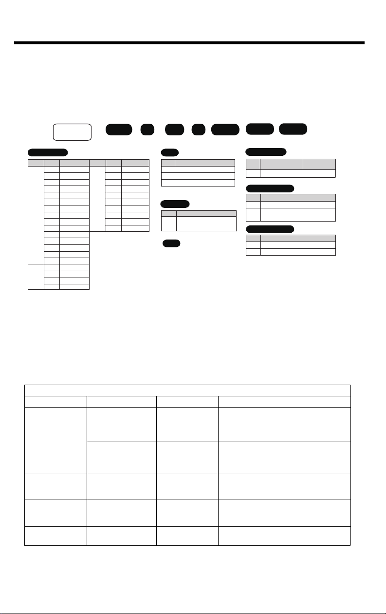
100V/200V Safety Standards and Performance Level
Certification marks for the standards for which the product has been certified by certification bodies are shown on nameplate. Products that do not have the marks are not certified for the standards.
North American Safety Standards (UL)
Product Model UL Standards (UL File No.)
SERVOPACKs • SGD7S
European Directives
Product Model European Direc tive Harmonized Standards
Machinery Directive
2006/42/EC
SERVOPAC Ks
• SGD7S
EMC Directive
2014/30/EU
Low Voltage Directive
2014/35/EU
UL 61800-5-1 (E147823),
CSA C22.2 No.274
EN ISO13849-1: 2015
EN 55011 group 1, class A
EN 61000-6-2
EN 61000-6-4
EN 61800-3
(Category C, Second environment)
EN 50178
EN 61800-5-1
Safety Standards
Product Model European Di rective Harmonized Standards
EN IOSO13849-1:2015
IEC 60204-1
IEC 61508 series
IEC 62061
IEC61800-5-2
SERVOPAC Ks
• SGD7S
Safety of Machinery
Functional Safety
EMC IEC 61326-3-1
3
Page 4
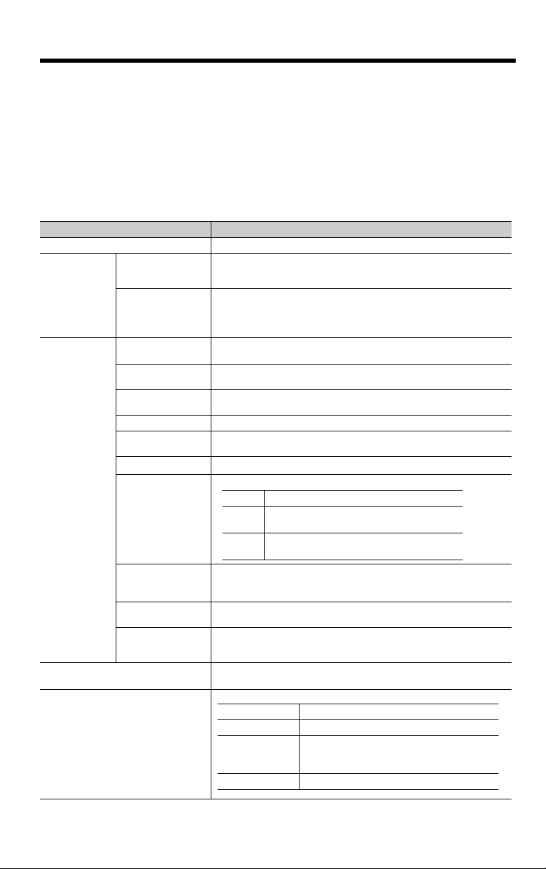
Safety Performance Amplifier Alone
Items Standards Performance Level
Safety Integrity Level
Mission Time
Probability of Dangerous
Failure per Hour
Performance Level
Mean Time to Dangerous
Failure of Each Channel
Average Diagnostic
Coverage
Stop Category
Safety Function
Hardware Fault Tolerance
Subsystem
IEC 61508 SIL3
IEC 62061 SILCL3
IEC 61508 10 years 20 years
IEC 61508
IEC 62061
EN ISO
13849-1
EN ISO
13849-1
EN ISO
13849-1
IEC 60204-1 Stop category 0
IEC
61800-5-2
IEC 61508 HFT = 1
IEC 61508 B
PFH = 4.60 x 10
4.60% of SIL3
PLe (Category 3)
MTTFd: High
DCavg: Medium
STO
Safety Performance with Safety Module
Items Standards Performance Level
Safety Integrity Level
Probability of Dangerous
Failure per Hour
Performance Level
Mean Time to Dangerous
Failure of Each Channel
Average Diagnostic
Coverage
Safety Function
Mission Time
Hardware Fault Tolerance
Subsystem
IEC 61508 SIL2
IEC 62061 SILCL2
IEC 61508
IEC 62061
EN ISO 13849-1 PL d (Category 2)
EN ISO 13849-1 MTTFd: High
EN ISO 13849-1 DCavg: Medium
IEC 61800-5-2 STO/SS1/SS2/SLS
IEC 61508 10 Years
IEC 61508 HFT = 1
IEC 61508 B
PFH = 3.3 x 10
3.3% of SIL2
-9
[1/h]
PFH = 4.62 x 10⁻⁹ [1/h]
4.62% of SIL3
-7
[1/h]
4
Page 5

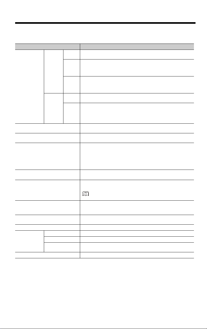
400V Safety Standards and Performance Level
Certification marks for the standards for which the product has been certified by certification bodies are shown on nameplate. Products that do not have the marks are not certified for the standards.
North American Safety Standards (UL)
Product Model UL Standards (UL File No.)
SERVOPACKs • SGD7S
European Directives
Product Model European Di rective Harmonized Standards
Machinery Directive
2006/42/EC
SERVOPAC Ks
• SGD7S
EMC Directive
2014/30/EU
Low Voltage Directive
2014/35/EU
RoHS Directive 2011/65/EU EN 50581
UL 61800-5-1 (E147823),
CSA C22.2 No.274
EN ISO13849-1: 2015
EN 55011 group 1, class A
EN 61000-6-2
EN 61000-6-4
EN 61800-3
(Category C, Second environment)
EN 50178
EN 61800-5-1
Safety Standards
Product Model European Di rective Harmonized Standards
EN IOSO13849-1:2015
IEC 60204-1
IEC 61508 series
IEC 62061
IEC61800-5-2
SERVOPAC Ks
• SGD7S
Safety of Machinery
Functional Safety
EMC IEC 61326-3-1
5
Page 6

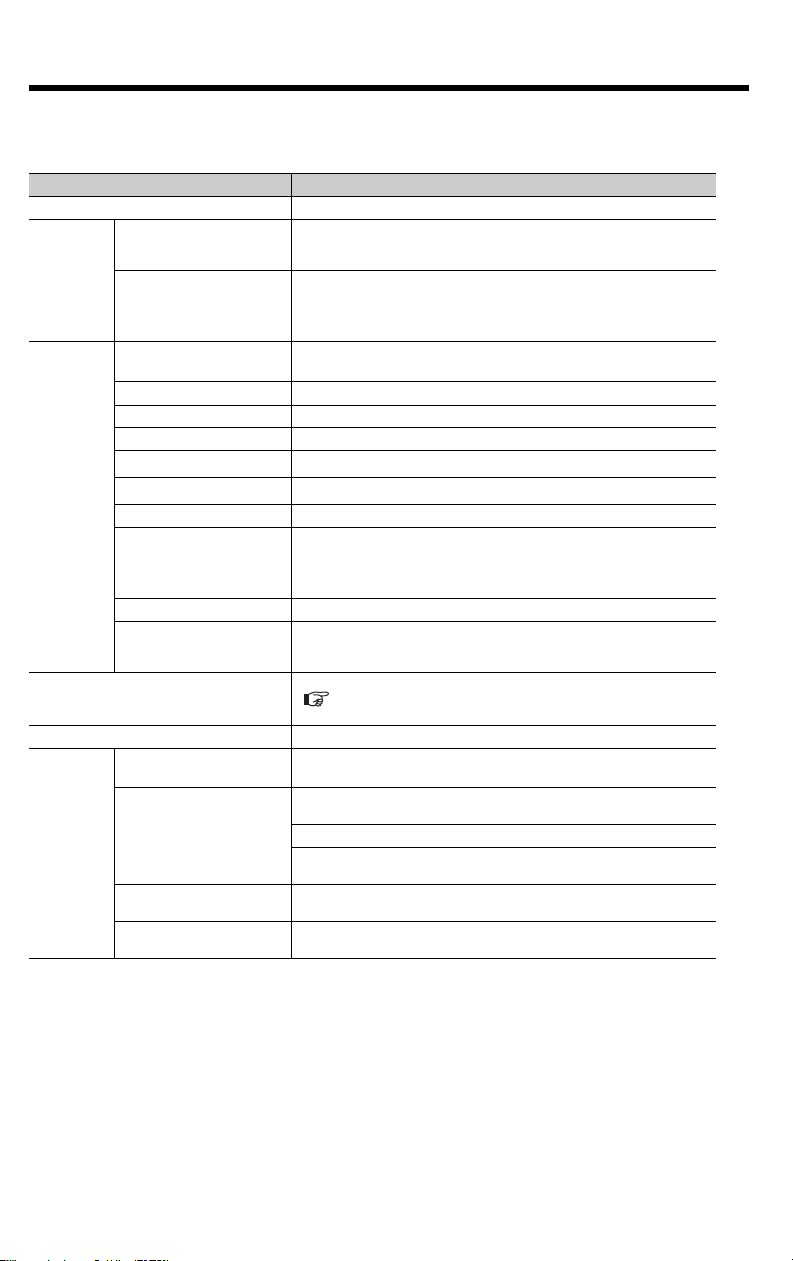
Safety Performance Amplifier Alone
Items Standards Performance Level
Safety Integrity Level
Mission Time
Probability of Dangerous
Failure per Hour
Performance Level
Mean Time to Dangerous
Failure of Each Channel
Average Diagnostic
Coverage
Stop Category
Safety Function
Hardware Fault Tolerance
Subsystem
IEC 61508 SIL3
IEC 62061 SILCL3
IEC 61508 10 years 20 years
IEC 61508
IEC 62061
EN ISO
13849-1
EN ISO
13849-1
EN ISO
13849-1
IEC 60204-1 Stop category 0
IEC
61800-5-2
IEC 61508 HFT = 1
IEC 61508 B
PFH = 4.60 x 10
4.60% of SIL3
PLe (Category 3)
MTTFd: High
DCavg: Medium
STO
Safety Performance with Safety Module
Items Standards Performance Level
Safety Integrity Level
Probability of Dangerous
Failure per Hour
Performance Level
Mean Time to Dangerous
Failure of Each Channel
Average Diagnostic
Coverage
Safety Function
Mission Time
Hardware Fault Tolerance
Subsystem
IEC 61508 SIL2
IEC 62061 SILCL2
IEC 61508
IEC 62061
EN ISO 13849-1 PL d (Category 2)
EN ISO 13849-1 MTTFd: High
EN ISO 13849-1 DCavg: Medium
IEC 61800-5-2 STO/SS1/SS2/SLS
IEC 61508 10 Years
IEC 61508 HFT = 1
IEC 61508 B
PFH = 3.3 x 10
3.3% of SIL2
-9
[1/h]
PFH = 4.62 x 10⁻⁹ [1/h]
4.62% of SIL3
-7
[1/h]
6
Page 7

Table of Contents
1 Introduction
1.1 Sigma-7Siec Features - - - - - - - - - - - - - - - - - - - - - - - -3
1.2 Sigma-7Siec Appearance - - - - - - - - - - - - - - - - - - - - - -4
1.3 Model Number Designation - - - - - - - - - - - - - - - - - - - -6
1.4 Accessories - - - - - - - - - - - - - - - - - - - - - - - - - - - - - - -6
2 Specifications and Settings
2.1 Specifications - - - - - - - - - - - - - - - - - - - - - - - - - - - - - -7
2.2 DIP Switch Settings - - - - - - - - - - - - - - - - - - - - - - - - -13
2.3 Rotary Switches - - - - - - - - - - - - - - - - - - - - - - - - - - -14
2.4 Switch Factory Settings - - - - - - - - - - - - - - - - - - - - - -14
3 Installation Standards
3.1 Mechanical Installation/Dimensions - - - - - - - - - - - - - -15
3.2 Installing Multiple SERVOPACKS in a Control Panel -16
4 Inputs and Outputs
4.1 Input Signals - - - - - - - - - - - - - - - - - - - - - - - - - - - - - -19
4.2 Output Signals - - - - - - - - - - - - - - - - - - - - - - - - - - - -21
4.3 I/O Signal Connector (CN1) Pin Arrangement - - - - - -23
4.4 I/O Signal Wiring Examples - - - - - - - - - - - - - - - - - - -25
4.5 I/O Circuits - - - - - - - - - - - - - - - - - - - - - - - - - - - - - - -29
5 LED Outputs - - - - - - - - - - - - - - - - - - - - - - - - - - - - - - - 31
6 Ethernet Connectivity
6.1 Ethernet Connector Details - - - - - - - - - - - - - - - - - - -33
6.2 Ethernet Cable - - - - - - - - - - - - - - - - - - - - - - - - - - - -34
6.3 Ethernet Connection Examples - - - - - - - - - - - - - - - - -34
1
Page 8

7 Cable Diagrams
7.1 SBK-U-VBA-xx (200V Only) - - - - - - - - - - - - - - - - - - -37
7.2 JZSP-CSI02-x-E (200V Only) - - - - - - - - - - - - - - - - - -38
8 EMC Installation Conditions - - - - - - - - - - - - - - - - - - 39
9 Safety - - - - - - - - - - - - - - - - - - - - - - - - - - - - - - - - - - - - 43
9.1 Safety Modules - - - - - - - - - - - - - - - - - - - - - - - - - - - -43
9.2 Safety Module Installation - - - - - - - - - - - - - - - - - - - -43
9.3 Supported Safety Functions - - - - - - - - - - - - - - - - - - -43
9.4 Relationship with Function Blocks for Motion - - - - - - -43
9.5 Risk Assessment - - - - - - - - - - - - - - - - - - - - - - - - - - -44
2
Page 9

1 Introduction
1.1 Sigma-7Siec Features
The Sigma-7Siec is a single-axis machine controller that is enclosed
inside a Sigma-7 servo amplifier, providing a compact, all-in-one
servo/controller package with the following features:
PLCopen for Motion Control, including indexing, virtual camming, and
servo parameter maintenance capability. Multiple communications protocols are supported, including: Modbus/TCP, EtherNet/IP, OPC and
user customizable socket communications.
Sigma-7 self-tuning, anti-vibration, and other high performance,
easy-to-implement servo control features.
1
Introduction
3
Page 10
1
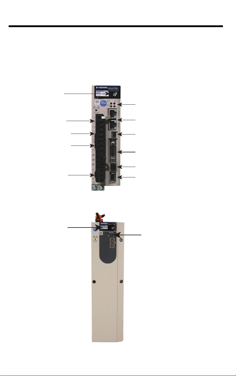
Switches
(under cover)
Main Circuit
Power Supply
Control Circuit
Power Supply
Servo Motor
Power
Regenerative
Resistor
Connections
LED Indicators
CN6A/B: Ethernet
CN7: USB
CN1: SERVOPACK I/O
CN8: HWBB
CN2: Encoder
Switches
(under cover)
LED Indicators
Introduction
1.2 Sigma-7Siec Appearance
The following figures show the external appearance of the Sigma-7Siec
controller.
4
200V Front View
400V Front View
Page 11

400V Top View
CN101:
Main Circuit
Power Supply
CN103:
DC Bus
Terminals
CN201: Control
Circuit Power Supply
CN7: USB
CN2: Encoder
CN8: HWBB
CN1:
SERVOPACK I/O
CN6A/B: Ethernet
1
Introduction
CN102: Servo
Motor Power
CN115:
Dynamic Brake
400V Bottom View
5
Page 12
1
2R8 A
M0
A
000 F50
M0
SGD7S -
F50
FT/EX Specification
Application function for Sigma-7Siec
F82
Application function for Sigma-7Siec
with support for SGM7D motors
A 200 VAC
D 400 VAC
F 100 VAC
A: Global design revision
B: 400V Global design revision
R70
*2
R90
*2
1R6
*2
2R8
*2
3R8
5R5
*2
7R6
120
180
200
330
470
550
590
780
R70
R90
2R1
2R8
0.05 kW
0.1 kW
0.2 kW
0.4 kW
0.5 kW
0.75 kW
1.0 kW
1.5 kW
2.0 kW
3.0 kW
5.0 kW
6.0 kW
7.5 kW
11 kW
15 kW
0.05 kW
0.1 kW
0.2 kW
0.4 kW
Maximum Applicable
Motor Capacity
Voltage
Interface
Code
Code
Specification
Code
000
Specification
Without options
All models
Applicable
Models
Specification
Sigma-7Siec
(built-in single-axis control)
Design Revision Order
Hardware Options
Specification
Voltage Code Specification Voltage Code Specification
Threephase,
200
VAC
1R9
3R5
5R4
8R4
120
170
210
*4
260
*4
280
*4
370
*4
500 W
1.0 kW
1.5 kW
2.0 kW
3.0 kW
5.0 kW
6.0 kW
7.5 kW
11 kW
15 kW
Threephase,
400
VAC
Singlephase,
100
VAC
1st+2nd+3rd digits
4th digit
5th+6th digits
7th digit
8th+9th+10th digits
-7 Series
SERVOPACK
4th
digit
1st+2nd+3rd
digits
5th+6th
digits
8th+9th+10th
digits
7th
digit
11th+12th+
13th digits
_ _ _
14th+15th+
16th digits
11th+12th+13th digits
Code
Specification
Blank
Option Module
Standard
010
*1
Safety Module
*3
14th+15th+16th digits
Code
Specification
Introduction
1.3 Model Number Designation
1.4 Accessories
Type Description Model Number Note
CN1 Terminal Block
Conversion Kit
CN1 Cable (Flying
leads)
Module cover and
mounting plate for
200V amps
Mounting plate for
400V amps
Accessories and
Cables (100 VAC
and 200 VAC)
Communication Ethernet Cable
Option Case Kit
Option Case Kit
6
System Components
xx denotes cable length
SBK-U-MP2Bxx
JZSP-CSI02-x-E
Customer
Supplied
SGDV-OZA01A Used for mounting safety module
JZSP-P7R2-8-E Using for mounting safety module
A5: 0.5 m
01: 1.0 m
03: 3.0 m
x denotes cable length
A: 1.0 m
B: 2.0 m
C: 3.0 m
Use high quality shielded industrial
Ethernet cables (Yaskawa model
JZSP-CM3RRM0-xx-E is recommended)
Page 13
2 Specifications and Settings
Degree SERVOPACK Model: SGD7S-
IP20
R70A, R90A, 1R6A, 2R8A, 3R8A, 5R5A,
7R6A, 120A, R70F, R90F, 2R1F, 2R8F
IP10
180A, 200A, 330A, 470A, 550A, 590A,
780A
Mounting SERVOPACK Model: SGD7S-
Base-mounted All Models
Rack-mounted
R70A, R90A, 1R6A, 2R8A, 3R8A, 5R5A,
7R6A, 120A, 180A, 200A, 330A, R70F,
R90F, 2R1F, 2R8F
Duct-ventilated 470A, 550A, 590A, 780A
2.1.1 200 VAC Specifications
2 Specifications and Settings
2.1 Specifications
2.1.1 200 VAC Specifications
Item Specification
Control Method IGBT-based PWM control, sine wave current drive
Serial encoder: 20 bits or 24 bits (incremental encoder/
• Absolute linear encoder (The signal resolution depends on the
absolute linear encoder.)
• Incremental linear encoder (The signal resolution depends on
the incremental linear encoder or Serial Converter Unit.)
-5°C to 55°C
(With derating, usage is possible between 55°C and 60°C.)
-20°C to 85°C
95% relative humidity max. (with no freezing or condensation)
2
4.9 m/s
2
19.6 m/s
absolute encoder)
22 bits (absolute encoder)
Feedback
With Rotary
Servomotor
With Linear
Servomotor
Surrounding Air
Temperature
Storage Temperature
Surrounding Air
Humidity
Storage Humidity 95% relative humidity max. (with no freezing or condensation)
Vibration
Resistance
Shock Resistance
Environmental Conditions
Applicable Standards
Mounting
Degree of
Protection
Pollution Degree
Altitude
Others
• Must be no corrosive or flammable gases.
• Must be no exposure to water, oil, or chemicals.
• Must be no dust, salts, or iron dust.
1,000 m or less. (With derating, usage is possible between 1,000
m and 2,000 m.)
Do not use the SERVOPACK in the following locations: Locations
subject to static electricity noise, strong electromagnetic/magnetic
fields, or radioactivity
Compliance with UL Standards, EU Directives and Other Safety
Standards
7
Page 14

2 Specifications and Settings
2.1.1 200 VAC Specifications
Item Specification
Speed Control
Range
Coefficient of
Performance
I/O Signals
I/O Signals
Speed Fluctuation
Torque Control
Precision (Repeatability)
Soft Start Time
Setting
Encoder Divided
Pulse Output
Linear Servomotor
Overheat Protection Signal Input
Input
Sig-
Digital
Input
Signals
Digital
Output
Signals
nals
That
Can
Be
Allocated
Fixed
Output
Output
Signals
That
Can Be
Allocated
(cont’d)
1:5000 (At the rated torque, the lower limit of the speed control
range must not cause the Servomotor to stop.)
±0.01% of rated speed max. (for a load fluctuation of 0% to 100%)
0% of rated speed max. (for a voltage fluctuation of ±10%)
±0.1% of rated speed max. (for a temperature fluctuation of 25°C
±25°C)
±1%
0 s to 10 s (Can be set separately for acceleration and deceleration.)
Phase A, phase B, phase C: Line-driver output
Number of divided output pulses: Any setting is allowed.
Number of input points: 1
Input voltage range: 0 V to +5 V
Allowable voltage range: 24 VDC ±20%
Number of input points: 7
Input method: Sink inputs or source inputs
Input Signals
• P-OT (Forward Drive Prohibit) and N-OT (Reverse Drive Prohibit) signals
• /EXT1 External latch signal input (General purpose input)
• /EXT2 External latch signal input (General purpose input)
• /EXT3 External latch signal input (General purpose input)
• /P-CL (Forward External Torque Limit) and /N-CL (Reverse
External Torque Limit) signals
• FSTP (Forced Stop Input) signal
A signal can be allocated and the positive and negative logic can
be changed.
Allowable voltage range: 5 VDC to 30 VDC
Number of output points: 1
Output signal: ALM (Servo Alarm) signal
Allowable voltage range: 5 VDC to 30 VDC
Number of output points: 3
(A photocoupler output (isolated) is used.)
Output Signals
• /COIN (Positioning Completion) signal
• /V-CMP (Speed Coincidence Detection) signal
• /TGON (Rotation Detection) signal
• /S-RDY (Servo Ready) signal
• /CLT (Torque Limit Detection) signal
• /VLT (Speed Limit Detection) signal
• /BK (Brake) signal
• /WARN (Warning) signal
• /NEAR (Near) signal
A signal can be allocated and the positive and negative logic can
be changed.
8
Page 15
2 Specifications and Settings
2.1.1 200 VAC Specifications
Item Specification
Interfaces
RS-422A
Communications
(CN502)
Communications
USB
Communications
(CN7)
Displays/Indicators
Ethernet IP Address Setting
Switches
Analog Monitor (CN5)
Dynamic Brake (DB)
Regenerative Processing
Overtravel (OT) Prevention
Protective Functions
Utility Functions Gain adjustment, alarm history, jogging, origin search, etc.
Inputs /HWBB1 and /HWBB2: Base block signals for Power Modules
Safety Functions
Applicable Option Modules Safety Module
Output EDM1: Monitors the status of built-in safety circuit (fixed output).
Applicable
Standards
1:N
Communications
Axis
Addres
s Setting
Interface
Communications
Standard
A JUSP-JC001 Communications Unit is required to connect to a
Digital Operator (JUSP-OP05A-1-E).
Up to N = 15 stations possible for RS-422A port
Set with parameters.
Personal computer (with SigmaWin+)
Conforms to USB2.0 standard (12 Mbps).
CHARGE, PWR, CN, RUN, ERR, and L/A (A and B) indicators,
and one-digit seven-segment display
Used to configure IP address
Number of points: 2
Output voltage range: ±10 VDC (effective linearity range: ±8 V)
Resolution: 16 bits
Accuracy: ±20 mV (Typ)
Maximum output current: ±10 mA
Settling time (±1%): 1.2 ms (Typ)
Activated when a servo alarm or overtravel (OT) occurs, or when
the power supply to the main circuit or servo is OFF.
Built-in (An external resistor must be connected to the SGD7S470A to -780A.)
Refer to the following manual for details.
S-7-Series AC Servo Drive Peripheral Device Selection
Manual (Manual No.: SIEP S800001 32)
Stopping with dynamic brake, deceleration to a stop, or coasting
to a stop for the P-OT (Forward Drive Prohibit) or N-OT (Reverse
Drive Prohibit) signal
Overcurrent, overvoltage, low voltage, overload, regeneration
error , etc.
ISO13849-1 PLe (Category 3), IEC61508 SIL3
(cont’d)
9
Page 16
2 Specifications and Settings
2.1.2 400 VAC Specifications
2.1.2 400 VAC Specifications
Item Specification
Control Method IGBT-based PWM control, sine wave current drive
With Rotary
Servomotor
Feedback
Environmental
Conditions
Applicable Standards
Mounting Base-mounted
Performance
With Linear
Servomotor
Surrounding Air
Temperature
Storage Temperature -20°C to 85°C
Surrounding Air Humidity 95% relative humidity max. (with no freezing or condensation)
Storage Humidity 95% relative humidity max. (with no freezing or condensation)
Vibration Resistance
Shock Resistance
Degree of Protection
Pollution Degree
Altitude 1,000 m or less.
Others
Speed Control Range
Coefficient of Speed
Fluctuation
Torque Control Precision
(Repeatability)
Soft Start Time
Setting
*1
*2
Serial encoder: 24 bits
• Absolute linear encoder (The signal resolution depends on
the absolute linear encoder.)
• Incremental linear encoder (The signal resolution depends
on the incremental linear encoder or Serial Converter Unit.)
-5°C to 55°C
2
4.9 m/s
2
19.6 m/s
IP10
2
• Must be no corrosive or flammable gases.
• Must be no exposure to water, oil, or chemicals.
• Must be no dust, salts, or iron dust.
Do not use the SERVOPACK in the following locations: Locations subject to static electricity noise, strong electromagnetic/
magnetic fields, or radioactivity
Refer to the following section for details.
Compliance with UL Standards, EU Directives, and Other
Safety Standards on page xxi
1:5000 (At the rated torque, the lower limit of the speed control
range must not cause the Servomotor to stop.)
±0.01% of rated speed max. (for a load fluctuation of 0% to
100%)
0% of rated speed max. (for a voltage fluctuation of ±10%)
±0.1% of rated speed max. (for a temperature fluctuation of
25°C ±25°C)
±1%
0 s to 10 s (Can be set separately for acceleration and deceleration.)
(incremental encoder/absolute
encoder)
10
Page 17

I/O Signals
Communications
Item Specification
Encoder Divided Pulse
Output
Linear Servomotor Overheat Protection Signal
Input
Input
Sequence
Input
Signals
Sequence
Output Signals
RS-422A
Communications
(CN502)
USB Communications (CN7)
Signals
That Can
Be
Allocated
Fixed
Output
Output
Signals
That Can
Be Allocated
Interfaces Digital Operator (JUSP-OP05A-1-E).
1:N
Communications
Axis
Address
Setting
Interface
Communications
Standard
Phase A, phase B, phase C: Line-driver output
Number of divided output pulses: Any setting is allowed.
Number of input points: 1
Input voltage range: 0 V to +5 V
Allowable voltage range: 24 VDC ±20%
Number of input points: 7
Input method: Sink inputs or source inputs
Input Signals
• P-OT (Forward Drive Prohibit) and N-OT (Reverse Drive Prohibit) signals
• /Probe1 (Probe 1 Latch Input) signal
• /Probe2 (Probe 2 Latch Input) signal
• /Home (Home Switch Input) signal
• /P-CL (Forward External Torque Limit) and /N-CL (Reverse
External Torque Limit) signals
• /SI0 and /SI3 (General-Purpose Input) signals
A signal can be allocated and the positive and negative logic
can be changed.
Allowable voltage range: 5 VDC to 30 VDC
Number of output points: 1
Output signal: ALM (Servo Alarm) signal
Allowable voltage range: 5 VDC to 30 VDC
Number of output points: 5
(A photocoupler output (isolated) is used.)
Output Signals
• /COIN (Positioning Completion) signal
• /V-CMP (Speed Coincidence Detection) signal
• /TGON (Rotation Detection) signal
• /S-RDY (Servo Ready) signal
• /CLT (Torque Limit Detection) signal
• /VLT (Speed Limit Detection) signal
• /BK (Brake) signal
• /WARN (Warning) signal
• /NEAR (Near) signal
• /ZONE0 (ZONE Signal 1 Output) signal
• /ZONE1 (ZONE Signal 2 Output) signal
• /ZONE2 (ZONE Signal 3 Output) signal
• /ZONE3 (ZONE Signal 4 Output) signal
• /nZONE (nZONE Output) signal
A signal can be allocated and the positive and negative logic
can be changed.
Up to N = 15 stations possible for RS-422A port
Set with parameters.
Personal computer (with SigmaWin+)
The software version of the SigmaWin+ must be version 7.11 or
higher.
Conforms to USB2.0 standard (12 Mbps).
2 Specifications and Settings
2.1.2 400 VAC Specifications
11
Page 18

2 Specifications and Settings
× 100%
Coefcient of speed uctuation =
No-load motor speed - Total-load motor speed
Rated motor speed
2.1.2 400 VAC Specifications
Item Specification
Displays/Indicators
Ethernet IP Address Setting Switches Used to configure IP address
Analog Monitor (CN5)
Dynamic Brake (DB)
Regenerative Processing
Overtravel (OT) Prevention
Protective Functions
Utility Functions Gain adjustment, alarm history, jogging, origin search, etc.
Inputs /HWBB1 and /HWBB2: Base block signals for Power Modules
Safety
Functions
* 1. If you combine a -7-Series SERVOPACK with a -V-Series Option Module, the surrounding air tempera-
* 2. The coefficient of speed fluctuation for load fluctuation is defined as follows:
Output
Applicable
Standards
ture specification of the -V-Series SERVOPACKs must be used, i.e., 0°C to 55°C. Also, the applicable
surrounding range cannot be increased by derating.
*3
CHARGE, PWR, RUN, ERR, and L/A (A and B) indicators, and
one-digit seven-segment display
Number of points: 2
Output voltage range: ±10 VDC (effective linearity range: ±8 V)
Resolution: 16 bits
Accuracy: ±20 mV (Typ)
Maximum output current: ±10 mA
Settling time (±1%): 1.2 ms (Typ)
Activated when a servo alarm or overtravel (OT) occurs, or
when the power supply to the main circuit or servo is OFF.
Built-in
Refer to the catalog for details.
Stopping with dynamic brake, deceleration to a stop, or coasting to a stop for the P-OT (Forward Drive Prohibit) or N-OT
(Reverse Drive Prohibit) signal
Overcurrent, overvoltage, low voltage, overload, regeneration
error, etc.
EDM1: Monitors the status of built-in safety circuit (fixed output).
ISO13849-1 PLe (category 3), IEC61508 SIL3
* 3. Always perform risk assessment for the system and confirm that the safety requirements are met.
12
Page 19

2.2 DIP Switch Settings
DIP Switches
Rotary
Switches
(used to
set IP
address)
2 Specifications and Settings
2.1.2 400 VAC Specifications
1
2
3
4
Rotary Switch 1 Rotary Switch 0
Switch Name Setting Operating Mode
User program execution
ON
STOP
1
2
SUP
INIT
3
4
E-INIT
inhibited
OFF Normal operation
Firmware programming
ON
mode
OFF Normal operation
Configuration bypass
ON
mode
OFF Normal operation
ON Normal operation
OFF Rotary switches ignored
Setting for
Normal
Operation
OFF
OFF
OFF
OFF
Details
Inhibits user program execution
Enables servo controller firmware
programming. This mode can also be
enabled via web UI without changing
the DIP switch.
Set to ON to bypass the stored
configuration (e.g. in case of a
configuration problem that prevents
servo controller startup)
Rotary switches used to set IP address
IP address is set from configuration
settings in servo controller
13
Page 20

2 Specifications and Settings
2.1.2 400 VAC Specifications
2.3 Rotary Switches
When DIP switch 4 (E-INIT) is OFF, the rotary switches are ignored.
The IP address is set from configuration settings stored on the servo
controller.
Rotary switches are normally used to set the IP address. This is the
case when DIP switch 4 (E-INIT) is ON
If both rotary switches are set to 0, use DHCP.
If either rotary switch is non zero, the last octet of the IP address is set
by the value on the switches. Note that the switch values are labeled in
hexadecimal. The IP address will be 192.168.1.x where x is 0x01 to
0xFF for a decimal value of 01 to 255.
Rotary Switch 1 Rotary Switch 0 IP Address
0 0 Set by DHCP
0 1 192.168.1.1
0 2 192.168.1.2
... ... ...
0 F 192.168.1.15
1 0 192.168.1.16
... ... ...
1 F 192.168.1.31
2 0 192.168.1.32
... ... ...
F F 192.168.1.255
2.4 Switch Factory Settings
All DIP switches off
Rotary switch 0 setting = 0. Rotary switch 1 setting = 1.
Configured IP address is 192.168.1.1
14
Page 21

3 Installation Standards
3 Installation Standards
3.1 Mechanical Installation/Dimensions
The Sigma-7Siec servo interface is based on the Sigma-7S
EtherCAT servo amplifier. As such, it has the same envelope and
mechanical installation directions. Please refer to section 2.3 of the
Sigma-7S EtherCAT (CoE) Communications Reference Product
Manual (document number SIEPS80000155)
15
Page 22

3 Installation Standards
Important
3.2.1 200V SERVOPACKS
3.2 Installing Multiple SERVOPACKS in a Control Panel
3.2.1 200V SERVOPACKS
Provide the following intervals between the SERVOPACKs and
spaces around the SERVOPACKs.
Install cooling fans above the SERVOPACKs so that hot
spots do not occur around the SERVOPACKs. Provide
sufficient intervals and spaces as shown in the following
figure to enable cooling by the fans and natural convection.
40 mm min.
Fan
SERVOPACK
30 mm min.
This distance depends
on the model.
Fan
SERVOPACK
SERVOPACK
30 mm min.
SERVOPACK
40 mm min.
The space required on the right side of a SERVOPACK (when
looking at the SERVOPACK from the front) depends on the
SERVOPACK models. Refer to the following table.
Cooling Fan Installation
Conditions
10 mm above SERVO-
PACK’s Top Surface
SGD7S-
SERVOPACK Model
R70A, R90A, 1R6A, 2R8A,
3R8A, 5R5A, 7R6A, R70F,
R90F, 2R1F, 2R8F
120A, 180A, 200A, 330A,
470A, 550A, 590A, 780A
Space on
Right Side
1 mm min. Air speed: 1.0 m/s min.
10 mm min. Air speed: 1.0 m/s min.
16
Page 23

3.2.2 400V SERVOPACKS
Important
Fan
30 mm min.
30 mm min.
Fan
120 mm min.
120 mm min.
SERVOPACK
SERVOPACK
SERVOPACK
SERVOPACK
400 V SERVOPACKS can be mounted side-by-side as shown.
Install cooling fans above the SERVOPACKs so that hot
spots do not occur around the SERVOPACKs.
3 Installation Standards
3.2.2 400V SERVOPACKS
SGD7S-
SERVOPACK Model
1R9D, 3R5D, 5R4D, 8R4D,
120D, 170D, 210D, 260D,
280D, 370D
Cooling Fan Installation Conditions
10 mm above SERVOPACK’s Top Surface
Air speed: 1.0 m/s min.
17
Page 24

3 Installation Standards
3.2.2 400V SERVOPACKS
18
Page 25

4 Inputs and Outputs
4.1 Input Signals
4.1.1 200V SERVOPACKS
Default settings are provided in parentheses
4 Inputs and Outputs
4.1.1 200V SERVOPACKS
Signal
/SI1
(P-OT)
/SI2
(N-OT)
/SI3
/SI4
(/EXT1)
/SI5
(/EXT2)
/SI6
(/EXT3)
/SI0
+24VIN
BAT+
BAT-
TH 5
Note: If forward drive prohibition or reverse drive prohibition is used, the SERVOPACK is stopped
by software controls. If the application does not satisfy the safety requirements, add external
safety circuits as required.
Pin
No.
General-purpose Sequence
7
Input 1 (Forward Drive Prohibit
Input)
General-purpose Sequence
8
Input 2 (Reverse Drive Prohibit
Input)
General-purpose Sequence
9
Input 3
External latch signal 1 input
10
(General purpose input 4)
External latch signal 2 input
11
(General purpose input 5)
External latch signal 3 input
12
(General purpose input 6)
General-purpose Sequence
13
Input 0
Sequence Input Signal Power
6
Supply Input
14 Battery for Absolute Encoder (+) These are the pins to connect the absolute
15 Battery for Absolute Encoder (-)
Linear Servomotor Overheat
Protection Input
Name Function
You can allocate the input signal to use with
a parameter.
(Stops Servomotor drive (to prevent overtravel) when the moving part of the machine
exceeds the range of movement.)
You can allocate the input signal to use with
parameters.
(Used for general-purpose input.)
You can allocate the input signals to use with
parameters.
You can allocate the input signal to use with
a parameter.
(Used for general-purpose input.)
Inputs the sequence input signal power supply.
Allowable voltage range: 24 VDC ±20% The
24-VDC power supply is not provided by Yaskawa.
encoder backup battery.
Do not connect these pins if you use the
Encoder Cable with a Battery Case.
Inputs the overheat protection signal from a
Linear Servomotor.
19
Page 26

4 Inputs and Outputs
4.1.2 400V SERVOPACKS
4.1.2 400V SERVOPACKS
Default settings are given in parentheses.
Signal Pin No. Name Function
/SI1
(P-OT)
/SI2
(N-OT)
/SI3
/SI4
(/Probe1)
/SI5
(/Probe2)
/SI6
(/Home)
/SI0
+24VIN
BAT+
BAT-
TH 5
7
8
9
10
11
12
13
6
14
15
General-purpose
Sequence Input 1 (Forward Drive Prohibit
Input)
General-purpose
Sequence Input 2
(Reverse Drive Prohibit
Input)
General-purpose
Sequence Input 3
General-purpose
Sequence Input 4
(Probe 1 Latch Input)
General-purpose
Sequence Input 5
(Probe 2 Latch Input)
General-purpose
Sequence Input 6
(Home Switch Input)
General-purpose
Sequence Input 0
Sequence Input Signal
Power Supply Input
Battery for Absolute
Encoder (+)
Battery for Absolute
Encoder (-)
Linear Servomotor
Overheat Protection
Input
You can allocate the input signal to use with a
parameter. (Stops Servomotor drive (to prevent
overtravel) when the moving part of the machine
exceeds the range of movement.)
You can allocate the input signal to use with
parameters. (Used for general-purpose input.)
You can allocate the input signals to use with
parameters. (Connect the external signals that
latch the current feedback pulse counter.)
You can allocate the input signal to use with
parameters. (Connect the switch that starts
homing.)
You can allocate the input signal to use with a
parameter. (Used for general-purpose input.)
Inputs the sequence input signal power supply.
Allowable voltage range: 24 VDC ±20% The 24VDC power supply is not provided by Yaskawa.
These are the pins to connect the absolute
encoder backup battery. Do not connect these
pins if you use the Encoder Cable with a Battery
Case.
Inputs the overheat protection signal from a Linear Servomotor.
Note: If forward drive prohibition or reverse drive prohibition is used, the SERVOPACK is
stopped by software controls. If the application does not satisfy the safety requirements,
add external safety circuits as required.
20
Page 27

4.2 Output Signals
4.2.1 200V SERVOPACKS
Default settings are provided in parentheses.
4 Inputs and Outputs
4.2.1 200V SERVOPACKS
1
2
Pin
No.
Name Function
Servo Alarm Output Turns OFF (opens) when an error is detected.
General-purpose
Sequence Output 1
(Brake Output)
General-purpose
Sequence Output 2
General-purpose
Sequence Output 3
Pulse Output, Phase
A
Pulse Output, Phase
B
Pulse Output, Phase C Outputs the origin signal once every encoder rotation.
You can allocate the output signal to use with a parameter.
(Controls the brake. The brake is released when the signal
turns ON (closes).)
Used for general-purpose outputs.
Set the parameters to allocate functions.
Output the encoder divided pulse output signals with a 90°
phase differential.
Connected to the frame ground if the shield of the I/O Signal
Cable is connected to the connector shell.
Signal
ALM+ 3
ALM- 4
/SO1+
(/BK+)
/SO1(/BK-)
/SO2+ 23
/SO2- 24
/SO3+ 25
/SO3- 26
PAO 17 Encoder Divided
/PAO 18
PBO 19 Encoder Divided
/PBO 20
PCO 21 Encoder Divided
/PCO 22
SG 16 Signal ground This is the 0-V signal for the control circuits.
FG Shell Frame ground
21
Page 28

4 Inputs and Outputs
4.2.2 400V SERVOPACKS
4.2.2 400V SERVOPACKS
Default settings are provided in parentheses.
1
2
Pin
No.
Name Function
Servo Alarm Output Turns OFF (opens) when an error is detected.
General-purpose
Sequence Output 1
(Brake Output)
General-purpose
Sequence Output 2
General-purpose
Sequence Output 3
General-purpose
Sequence Output 4
General-purpose
Sequence Output 5
Pulse Output, Phase
A
Pulse Output, Phase
B
You can allocate the output signal to use with a parameter.
(Controls the brake. The brake is released when the signal turns ON (closes).)
Used for general-purpose outputs.
Set the parameters to allocate functions.
Output the encoder divided pulse output signals with a
90° phase differential.
Signal
ALM+ 3
ALM- 4
/SO1+
(/BK+)
/SO1(/BK-)
/SO2+ 23
/SO2- 24
/SO3+ 25
/SO3- 26
/SO4+ 27
/SO4- 28
/SO5+ 29
/SO5- 30
PAO 17 Encoder Divided
/PAO 18
PBO 19 Encoder Divided
/PBO 20
22
Page 29

4 Inputs and Outputs
4.3.1 200V SERVOPACKS
4.3 I/O Signal Connector (CN1) Pin Arrangement
4.3.1 200V SERVOPACKS
The following figure gives the pin arrangement of the of the I/O signal
connector (CN1) for the default settings.
Pin 1
Pin 2
Pin 12
Pin 13
The above
view is from
the direction
of the following arrow without the
connector
shell attached
.
Pin 14
Pin 15
Pin 25
Pin 26
/SO1-
2
(/BK-)
4ALM-
+24VI
6
N
/SI2
8
(N-OT)
/SI4
10
(/EXT1)
/SI6
12
(/EXT3)
Generalpurpose
Sequence
Output 1
Servo
Alarm
Output
Sequence
Input Signal Power
Supply
Input
Generalpurpose
Sequence
Input 2
External
latch signal 1 input
(General
purpose
input 4)
External
latch signal 3 input
(General
purpose
input 6)
/SO1+
1
(/BK+)
3ALM+
5TH
/SI1
7
(P-OT)
/SI3
9
(/DEC)
/SI5
11
(/EXT2)
13 /SI0
Generalpurpose
Sequence
Output 1
Servo
Alarm
Output
Linear
Servomotor Overheat
Protection Input
Generalpurpose
Sequence
Input 1
Generalpurpose
Sequence
Input 3
External
latch signal 2
input
(General
purpose
input 5)
Generalpurpose
Sequence
Input 0
15 BAT-
17 PAO
19 PBO
21 PCO
23 /SO2+
25 /SO3+
Battery for
Absolute
Encoder (-)
Encoder
Divided
Pulse Output, Phase
A
Encoder
Divided
Pulse Output, Phase
B
Encoder
Divided
Pulse Output, Phase
C
Generalpurpose
Sequence
Output 2
Generalpurpose
Sequence
Output 3
14 BAT+
16 SG
18 /PAO
20 /PBO
22 /PCO
24 /SO2-
26 /SO3-
Battery for
Absolute
Encoder
(+)
Signal
Ground
Encoder
Divided
Pulse Output, Phase
A
Encoder
Divided
Pulse Output, Phase
B
Encoder
Divided
Pulse Output, Phase
C
Generalpurpose
Sequence
Output 2
Generalpurpose
Sequence
Output 3
23
Page 30

4 Inputs and Outputs
Pin
15
Pin
1
Pin
2
Pin
30
Pin
16
Pin
17
4.3.2 400V SERVOPACKS
4.3.2 400V SERVOPACKS
The following figure gives the pin arrangement of the of the I/O
signal connector (CN1) for the default settings.
No Signal Specification No Signal Specification
15
PG
BAT-
Battery for absolute
encoder (-)
30 /SO5-
General-purpose
sequence output 5
Top View of I/O Signal
Connector
Side View of I/O Signal
Connector
PG
14
BAT+
13 /SI0
/SI6
12
(/Home)
/SI5
11
(/
Probe2)
/SI4
10
(/
Probe1)
9/SI3
/SI2
8
(N-OT)
/SI1
7
(P-OT)
6 +24VIN
5TH
4 ALM- Servo alarm output 19 PBO
3 ALM+ Servo alarm output 18 /PAO
/SO1-
2
(/BK-)
Battery for absolute
encoder (+)
General-purpose
sequence input 0
General-purpose
sequence input 6
General-purpose
sequence input 5
General-purpose
sequence input 4
General-purpose
sequence input 3
General-purpose
sequence input 2
General-purpose
sequence input 1
Sequence input signal power supply input
Linear Servomotor
overheat protection
input
General-purpose
sequence output 1
29 /SO5+
28 /SO4-
27 /SO4+
26 /SO3-
25 /SO3+
24 /SO2-
23 /SO2+
22 /PCO
21 PCO
20 /PBO
17 PAO
General-purpose
sequence output 5
General-purpose
sequence output 4
General-purpose
sequence output 4
General-purpose
sequence output 3
General-purpose
sequence output 3
General-purpose
sequence output 2
General-purpose
sequence output 2
Encoder divided pulse
output, phase C
Encoder divided pulse
output, phase C
Encoder divided pulse
output, phase B
Encoder divided pulse
output, phase B
Encoder divided pulse
output, phase A
Encoder divided pulse
output, phase A
/SO1+
1
(/BK+)
24
General-purpose
sequence output 1
16 SG Signal ground
Page 31

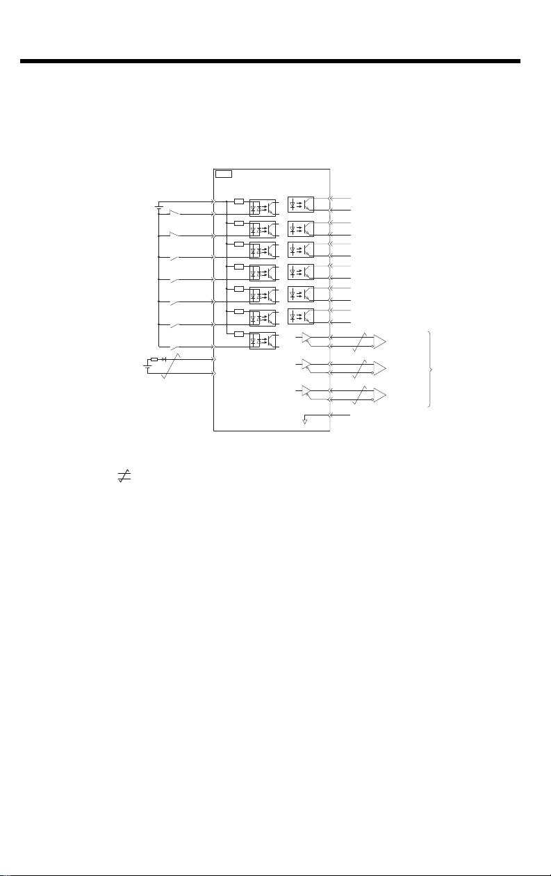
4.4 I/O Signal Wiring Examples
/BK+
/BK-
/SO2+
/SO2-
/SO3+
ALM+
ALM-
1
2
23
24
3
4
+24VIN
+24 V
*3
4.7 k
Ω
6
8
10
9
11
12
/SI0
P-OT
N-OT
General-purpose
sequence input 0
BAT+
BAT-
13
14
15
7
/SO3-
Forward Drive Prohibit input
(prohibited when OFF)
Sequence input signal
power supply input
Battery for
absolute encoder
Backup battery
*2
2.8 V to 4.5 V
Reverse Drive Prohibit input
(prohibited when OFF)
Brake output
(released when ON)
Servo Alarm Output
(OFF for alarm)
25
26
16
SG
*1
PBO
PCO
/PBO
PAO
/PAO
/PCO
21
17
18
19
20
22
FG
CN1
*4
*4
*4
Photocoupler outputs
Max. allowable voltage: 30 VDC
Max. allowable current: 50 mA DC
Encoder Divided
Pulse Output,
Phase A
Encoder Divided
Pulse Output,
Phase B
Encoder Divided
Pulse Output,
Phase C
Applicable Line
Receiver:
SN75ALS175 or
MC3486
manufactured
by Texas
Instruments or
the equivalent
Connect shield to connector shell.
Connector
shell
SERVOPACK
Frame ground
Signal ground
/SI3
/EXT1
/EXT2
/EXT3
External latch signal 1 input
(General purpose input 4)
General-purpose
sequence input 3
External latch signal 2 input
(General purpose input 5)
External latch signal 3 input
(General purpose input 6)
+
-
4.4.1 Using a Rotary Servo Motor
200V SERVOPACKS
4 Inputs and Outputs
4.4.1 Using a Rotary Servo Motor
* 1. represents twisted-pair wires.
* 2. Connect these when using an absolute encoder. If the Encoder Cable with a Battery Case
is connected, do not connect a backup battery.
* 3. The 24-VDC power supply is not provided by Yaskawa. Use a 24-VDC power supply with
double insulation or reinforced insulation.
* 4. Always use line receivers to receive the output signals.
Note: 1. You can use parameters to change the functions allocated to the /SI0, /SI3,
2. If you use a 24-V brake, install a separate power supply for the 24-VDC
P-OT, N-OT, /EXT1, /EXT2, and /EXT3 input signals and the /SO1, /SO2,
and /SO3 output signals.
power supply from other power supplies, such as the one for the I/O signals
of the CN1 connector.
If the power supply is shared, the I/O signals may malfunction.
25
Page 32
4 Inputs and Outputs
4.4.1 Using a Rotary Servo Motor
400V SERVOPACKS
Digital input signal
power supply input
Forward Drive Prohibit input
(prohibited when OFF)
Reverse Drive Prohibit input
(prohibited when OFF)
General-purpose
digital input 3
External latch signal 1 input
(General-purpose input 4)
General-purpose
digital input 5
General-purpose
digital input 6
General-purpose
digital input 0
Battery for
absolute encoder
*2
Backup battery
2.8 V to 4.5 V
*3
+24 V
*1
+
-
+24VIN
P-OT
N-OT
/SI3
/EXT1
/EXT2
/EXT3
/SI0
BAT+
BAT-
10
11
12
13
14
15
CN1
6
7
8
9
4.7 k
SERVOPACK
Photocoupler outputs
Max. allowable voltage: 30 VDC
Max. allowable current: 50 mA DC
ALM+
3
Servo Alarm Output
(OFF for alarm)
ALM-
4
/BK+
1
Brake output
(released when ON)
2
/BK-
23
/SO2+
/SO2-
24
25
/SO3+
/SO3-
26
27
/SO4+
/SO4-
28
29
/SO5+
/SO5-
30
17
PAO
18
/PAO
19
PBO
/PBO
20
21
PCO
22
/PCO
16
SG
*4
*4
*4
Signal ground
Encoder Divided
Pulse Output,
Phase A
Encoder Divided
Pulse Output,
Phase B
Encoder Divided
Pulse Output,
Phase C
Applicable line receiver:
SN75ALS175 or MC3486
manufactured by Texas
Instruments or the equivalent
26
* 1. represents twisted-pair wires.
* 2. Connect these when using an absolute encoder. If the Encoder Cable with a Battery Case
is connected, do not connect a backup battery.
* 3. The 24-VDC power supply is not provided by Yaskawa. Use a 24-VDC power supply with
double insulation or reinforced insulation.
* 4. Always use line receivers to receive the output signals.
Note: 1. You can use parameters to change the functions allocated to the /SI0, /SI3,
P-OT, N-OT, /EXT1, /EXT2, and /EXT3 input signals and the /SO1, /SO2,
and /SO3 output signals.
2. If you use a 24-V brake, install a separate power supply for the 24-VDC
power supply from other power supplies, such as the one for the I/O signals
of the CN1 connector. If the power supply is shared, the I/O signals may
malfunction.
Page 33

4.4.2 Using a Linear Servo Motor
200V SERVOPACKS
SERVOPACK
5
4.7 k
Ω
6
7
8
9
FG
Frame ground
Linear Servomotor overheat
protection input
Sequence input signal
power supply input
Forward Drive Prohibit input
(prohibited when OFF)
Reverse Drive Prohibit input
(prohibited when OFF)
General-purpose
sequence input 3
External latch signal 1 input
(General purpose input 4)
External latch signal 2 input
(General purpose input 5)
External latch signal 3 input
(General purpose input 6)
General-purpose
sequence input 0
+24 V *2
+24VIN
/EXT1
/EXT2
/EXT3
P-OT
N-OT
/SI3
CN1
TH
10
11
12
/SI0
13
4.4.2 Using a Linear Servo Motor
Photocoupler outputs
Max. allowable voltage: 30 VDC
Max. allowable current: 50 mA DC
ALM+
3
Servo Alarm Output
(OFF for alarm)
ALM-
4
/BK+
1
2
/BK-
23
/SO2+
/SO2-
24
25
/SO3+
/SO3-
26
*1
17
PAO
18
/PAO
19
PBO
/PBO
20
21
PCO
22
/PCO
16
SG
Connector
shell
Connect shield to connector shell.
4 Inputs and Outputs
Brake output
(released when ON)
*3
Encoder Divided
Pulse Output,
Phase A
*3
Encoder Divided
Pulse Output,
Phase B
*3
Encoder Divided
Pulse Output,
Phase C
Applicable Line Receiver:
SN75ALS175 or MC3486
manufactured by Texas
Instruments or the equivalent
* 1. represents twisted-pair wires.
* 2. The 24-VDC power supply is not provided by Yaskawa. Use a 24-VDC power supply with
double insulation or reinforced insulation.
* 3. Always use line receivers to receive the output signals.
Note: 1. You can use parameters to change the functions allocated to the /SI0, /SI3,
P-OT, N-OT, /EXT1, /EXT2, and /EXT3 input signals and the /SO1, /SO2,
and /SO3 output signals.
2. If you use a 24-V brake, install a separate power supply for the 24-VDC
power supply from other power supplies, such as the one for the I/O signals
of the CN1 connector.
If the power supply is shared, the I/O signals may malfunction.
27
Page 34

4 Inputs and Outputs
4.4.2 Using a Linear Servo Motor
400V SERVOPACKS
Linear Servomotor overheat
protection input
Digital input signal
power supply input
Forward Drive Prohibit input
(prohibited when OFF)
Reverse Drive Prohibit input
(prohibited when OFF)
General-purpose
digital input 3
External latch signal 1
input (General purpose
input 4)
General purpose
digital input 5
General purpose
digital input 6
General purpose
digital input 0
* 1. represents twisted-pair wires.
* 2. The 24-VDC power supply is not provided by Yaskawa. Use a 24-VDC power supply with
double insulation or reinforced insulation.
* 3. Always use line receivers to receive the output signals.
Note: 1. You can use parameters to change the functions allocated to the /SI0, /SI3,
2. If you use a 24-V brake, install a separate power supply for the 24-VDC
*2
+24 V
P-OT, N-OT, /EXT1, /EXT2, and /EXT3 input signals and the /SO1, /SO2,
and /SO3 output signals.
power supply from other power supplies, such as the one for the I/O signals
of the CN1 connector.
If the power supply is shared, the I/O signals may malfunction.
+24VIN
P-OT
N-OT
/SI3
/EXT1
/EXT2
/EXT3
/SI0
Photocoupler outputs
Max. allowable voltage: 30 VDC
SERVOPACK
CN1
TH
5
4.7 k
6
7
8
9
10
11
12
13
Max. allowable current: 50 mA DC
ALM+
3
Servo Alarm Output
(OFF for alarm)
ALM-
4
/BK+
1
Brake output
2
(released when ON)
/BK-
23
/SO2+
/SO2-
24
25
/SO3+
/SO3-
26
27
/SO4+
/SO4-
28
29
/SO5+
/SO5-
30
*1
17
PAO
18
/PAO
19
PBO
/PBO
20
21
PCO
22
/PCO
16
SG
*3
Encoder Divided
Pulse Output,
Phase A
*3
Encoder Divided
Pulse Output,
Phase B
*3
Encoder Divided
Pulse Output,
Phase C
Applicable line receiver:
SN75ALS175 or MC3486
manufactured by Texas
Instruments or the equivalent
28
Page 35

4.5 I/O Circuits
4.7 kΩ
e.g., /DEC
SERVOPACK
24 VDC
+24VIN
SERVOPACK input side
Switch
Photocoupler
Internal
signal
level
Internal
signal
level
Photocoupler
Switch
24 V
+
−
SERVOPACK input side
24 V
+
−
Switch
Photocoupler
Internal
signal
level
Internal
signal
level
Photocoupler
Switch
4.5.1 Sequence Input Circuits
Photocoupler Input Circuits
This section describes CN1 connector terminals 6 to 13.
4 Inputs and Outputs
4.5.1 Sequence Input Circuits
Examples for Relay Circuits
Examples for Open-Collector
Circuits
SERVOPACK
4.7 k
24 VDC
+24VIN
e.g., /DEC
Ω
Note: The 24-VDC external power supply capacity must be 50 mA minimum.
The SERVOPACK input circuits use bi-directional photocouplers.
Select either a sink circuit or source circuit according to the
specifications required by the machine.
Note: The connection examples in 4.4 I/O Signal Wiring Examples are for sink
circuit connections.
Sink Circuits Source Circuits
Photocoupler
Input Signal Polarity Input Signal Polarity
Internal Signal
Level
Photocoupler
Internal Signal
Level
ON Low level ON Low level
OFF High level OFF High level
29
Page 36

4 Inputs and Outputs
Important
0V
Relay
5 VDC to 30 VDC
SERVOPACK
SERVOPACK
5 VDC to 30 VDC
Applicable line receiver:
SN75ALS175 or MC3486
manufactured by Texas Instruments
or the equivalent
Output line driver:
SN75ALS174 or
the equivalent
Host controller
SERVOPACK
220 Ω to
470 Ω
4.5.2 Sequence Output Circuits
4.5.2 Sequence Output Circuits
Incorrect wiring or incorrect voltage application to the output circuits
may cause short-circuit failures.
If a short-circuit failure occurs as a result of any of these causes, the
holding brake will not work. This could damage the machine or cause
an accident that may result in death or injury.
Photocoupler Output Circuits
Photocoupler output circuits are used for the ALM (Servo Alarm), /S-RDY (Servo
Ready), and other sequence output signals. Connect a photocoupler output circuit
to a relay or line-receiver circuit.
Example for Relay Circuit Example for Line-Receiver Circuit
Note: The maximum allowable voltage and current range for photocoupler output circuits are
as follows:
• Maximum allowable voltage: 30 VDC
• Current range: 5 mA to 50 mA DC
Line-Driver Output Circuits
This section describes CN1 connector terminals 17-18 (Phase-A Signal), 19-20
(Phase-B Signal), and 21-22 (Phase-C Signal).
The serial data from the encoder is converted to two-phase (phases A and B)
pulses. The resulting output signals (PAO, /PAO and PBO, /PBO) and origin pulse
signal (PCO and /PCO) are output with line-driver output circuits. Connect the linedriver output circuits to line-receiver circuits at the host controller.
Example for Line-Receiver Circuit
30
Page 37

5 LED Outputs
The following indicators show the operating status of the servo
controller and error information.
ERR:
Solid at power up
Off when there is no error
Solid when there is an alarm
Blinking when there is a critical error
RUN:
Solid when internal logic controller is booted and ready
Blinking when internal logic controller is running a program
Ethernet Link/Activity:
Off when CN6A/B does not have an active Ethernet connection
Solid when CN6A/B has an active Ethernet connection
Blinking when CN6A/B is transmitting or receiving data
5 LED Outputs
31
Page 38

5 LED Outputs
32
Page 39

6 Ethernet Connectivity
Ethernet
The Sigma-7Siec supports both 100 Mbps/100Base-TX and 10 Mbps/
10Base-T connections. One single network is accessed using both
CN6A and CN6B. The same IP address is set for both ports. The
Ethernet address (MAC address) can be found on the nameplate.
6.1 Ethernet Connector Details
Ethernet Connector Specification and Pin Array
The following table provides the Ethernet connector specifications.
6 Ethernet Connectivity
Connector
Name
Ethernet
Number
of Pins
8
Module Side Cable Side Manufacturer
RJ-45 CAT5
Socket
Connector Model
RJ-45 CAT5
Plug
TE Connectivity
The following table provides Ethernet connector pin array details.
Pin Number Signal Name Description
1TXD+
2TXD-
3RXD+
4–
5–
6RXD-
7–
8–
Transmitted data + side
Transmitted data – side
Received data + side
–
–
Received data – side
–
–
33
Page 40

6 Ethernet Connectivity
100Base-TX
Ethernet Switch
Sigma-7Siec
100Base-TX
Ethernet Switch
100Base-TX
Station
StationStation
Up to 100m
Up to 100m
Up to 100m
Up to 100m
Up to 100m
Station
Up to 100m
Sigma-7Siec
6.2 Ethernet Cable
For the Ethernet cable, use a twisted pair cable with RJ-45
connector. Yaskawa strongly recommends the use of shielded
ethernet cables (Yaskawa model JZSP-CM3RRM0-xx-E). Ethernet
ports are capable of auto-crossover, so crossover cables are not
necessary.
6.3 Ethernet Connection Examples
Connection Example 1
34
Specification
Cable length from node to Ethernet hub or switch 100 m or less
Cable length between Ethernet hubs or switches 100 m or less
Number of Ethernet hubs or switches between nodes Unlimited
Page 41

Connection Example 2
100Base-TX
Ethernet Switch
Core
Core
100Base-TX
Servo motor
Station
Sigma-7Siec
Sigma-7Siec
Sigma-7Siec
Sigma-7Siec
100 Base-TX (up to 100m)
Connection Example 3
6 Ethernet Connectivity
Station
35
Page 42

6 Ethernet Connectivity
Model Manufacturer
E04SR301334
Seiwa Electric Mfg. Co., Ltd
Caution
Electromagnetic interference (EMI) may interfere with Ethernet communication.
The following measures can help minimize the influence of EMI:
1. Locate Ethernet cables so that they are well-separated from power cables or
other sources of EMI
2. Yaskawa strongly recommends the use of high-quality shielded Ethernet
cables such as JZSP-CM3RRM0-xx-E
3. Attach ferrite cores to Ethernet cables that are subjected to EMI
Recommended ferrite core:
36
Page 43

7 Cable Diagrams
Signal Function
1
/BK+ (/SO1+) Brake interlock output (+) (General purpose output 1 (+))
2
/BK- (/SO1-) Brake interlock output (-) (General purpose output 1 (-))
3 ALM+ Servo alarm output (+)
4 ALM- Servo alarm output (-)
56+24VIN
Control power supply for sequence signal input
7
P-OT (/SI1) Forward run prohibited input (General purpose input 1)
8
N-OT (/SI2) Reverse run prohibited input (General purpose input 2)
9
/DEC (/SI3) Zero-point return deceleration switch input (General purpose input 3)
10
/EXT1 (/SI4) External latch signal 1 input (General purpose input 4)
11
/EXT2 (/SI5) External latch signal 2 input (General purpose input 5)
12
/EXT3 (/SI6) External latch signal 3 input (General purpose input 6)
13 /SI0 General purpose input 0
14 BAT (+) Battery (+) input
15 BAT (-) Battery (-) input
16 SG Signal ground
17 PAO Phase-A pulse output (+)
18 /PAO Phase-A pulse output (-)
19 PBO Phase-B pulse output (+)
20 /PBO Phase-B pulse output (-)
21 PCO Phase-C pulse output (+)
22 /PCO Phase-C pulse output (-)
23 /SO2+ General purpose output 2 (+)
24 /SO2- General purpose output 2 (-)
25 /SO3+ General purpose output 3 (+)
26 /SO3- General purpose output 3 (-)
Mechatrolink-II type Servo Amplifier / Option type
Pin No.
SBK-U-VBA-xx Function Chart for Sigma-5 or Sigma-7 Servo Amplifier
Note: General purpose input and output signals are shown with their default signals assigned - signal
assignment may have been changed by parameter
7.1 SBK-U-VBA-xx (200V Only)
Terminal Block - CN1 I/O.
7 Cable Diagrams
37
Page 44

7 Cable Diagrams
/BK
+
/BK
−
ALM
+
ALM
−
–
+
24VIN
P-OT
N-OT
/DEC
/EXT1
/EXT2
/EXT3
/SI0
BAT
+
BAT
−
SG
PAO
/PAO
PBO
/PBO
PCO
/PCO
/SO2
+
/SO2
−
/SO3
+
/SO3
−
1
2
3
4
5
6
7
8
9
10
11
12
13
14
15
16
17
18
19
20
21
22
23
24
25
26
Blue
Blue
Pink
Pink
Green
Green
Orange
Orange
Gray
Gray
Blue
Blue
Pink
Pink
Green
Green
Orange
Orange
Gray
Gray
Blue
Blue
Pink
Pink
Green
Green
Red
Black
Red
Black
Red
Black
Red
Black
Red
Black
Red
Black
Red
Black
Red
Black
Red
Black
Red
Black
Red
Black
Red
Black
Red
Black
1
1
1
1
1
1
1
1
1
1
2
2
2
2
2
2
2
2
2
2
3
3
3
3
3
3
Pin No.
Wire
Color
Signal
Marking
Color
SERVOPACK End
Dots
Lead
Marker
1
2
3
4
5
6
7
8
9
10
11
12
13
14
15
16
17
18
19
20
21
22
23
24
25
26
Represents
twisted-pair
wires.
Host
Controller End
Model Cable Length
JZSP-CSI02-1-E 1000 mm
JZSP-CSI02-2-E 2000 mm
JZSP-CSI02-3-E 3000 mm
SERVOPACK End
Connector
10126-6000
EL (by Sumitomo 3M Ltd.
)
Shell
10326-52A0-008
Cable (Ivory
)
SSRFPVV-SB AWG#
28
× 13P
UL
20276
VW-1SC
L
37
.
2
14 100
+
10
-
0
3
Dia. Wire Markers
(
6
.
3
Dia.
)
Dimensions in mm
7.2 JZSP-CSI02-x-E (200V Only)
Flying Lead - CN1 I/O.
38
Page 45
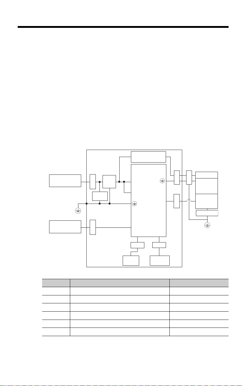
8
EMC Installation Conditions
8 EMC Installation Conditions
This section gives the installation conditions that were used for EMC
certification testing.
The EMC installation conditions that are given here are the conditions
that were used to pass testing criteria at Yaskawa. The EMC level may
change under other conditions, such as the actual installation structure
and wiring conditions. These Yaskawa products are designed to be
built into equipment. Therefore, you must implement EMC measures
and confirm compliance for the final equipment.
The applicable standards are EN 55011 group 1 class A, EN
61000-6-2, EN 61000-6-4, and EN 61800-3 (category C2, second
environment).
• Three-Phase, 200 VAC
Shield box
Brake power supply
SERVOPACK
Power supply:
Three-phase, 200 VAC
Noise
filter
Clamp
Surge
absorber
PE
L1, L2, and L3
L1C and L2C
U, V, and W
CN2
ClampClamp
Brake
Clamp
Servomotor
Encoder
Clamp
Host controller
Clamp
CN6A and CN6B
CN1
Clamp Clamp
I/O
controller
CN8
Safety
function device
PE
Symbol Cable Name Specification
I/O Signal Cable Shielded cable
Safety Function Device Cable Shielded cable
Servomotor Main Circuit Cable Shielded cable
Encoder Cable Shielded cable
Main Circuit Power Cable Shielded cable
Ethernet Communications Cable Shielded cable
39
Page 46

8
CN1
CN2
L1C and L2C
CN6A and CN6B
L1 and L2
U, V, and W
Noise
filter
Surge
absorber
Clamp
Brake
Servomotor
Encoder
Brake power supply
SERVOPACK
Safety
function device
I/O
controller
PE
PE
Shield box
Power supply:
Single-phase, 200 VAC
ClampClamp
Clamp
Clamp Clamp
Clamp
Host controller
Clamp
CN8
EMC Installation Conditions
• Single-Phase, 200 VAC
Symbol Cable Name Specification
I/O Signal Cable Shielded cable
Safety Function Device Cable Shielded cable
Servomotor Main Circuit Cable Shielded cable
Encoder Cable Shielded cable
Main Circuit Power Cable Shielded cable
Ethernet Communications Cable Shielded cable
40
Page 47
8
CN1
CN2
L1C and L2C
CN6A and CN6B
L1 and L2
U, V, and W
Noise
filter
Surge
absorber
Clamp
Brake
Servomotor
Encoder
Brake power supply
SERVOPACK
Safety
function device
I/O
controller
PE
PE
Shield box
Power supply:
Single-phase, 100 VAC
ClampClamp
Clamp
Clamp Clamp
Clamp
Host controller
Clamp
CN8
EMC Installation Conditions
• Single-Phase, 100 VAC
Symbol Cable Name Specification
I/O Signal Cable Shielded cable
Safety Function Device Cable Shielded cable
Servomotor Main Circuit Cable Shielded cable
Encoder Cable Shielded cable
Main Circuit Power Cable Shielded cable
Ethernet Communications Cable Shielded cable
41
Page 48

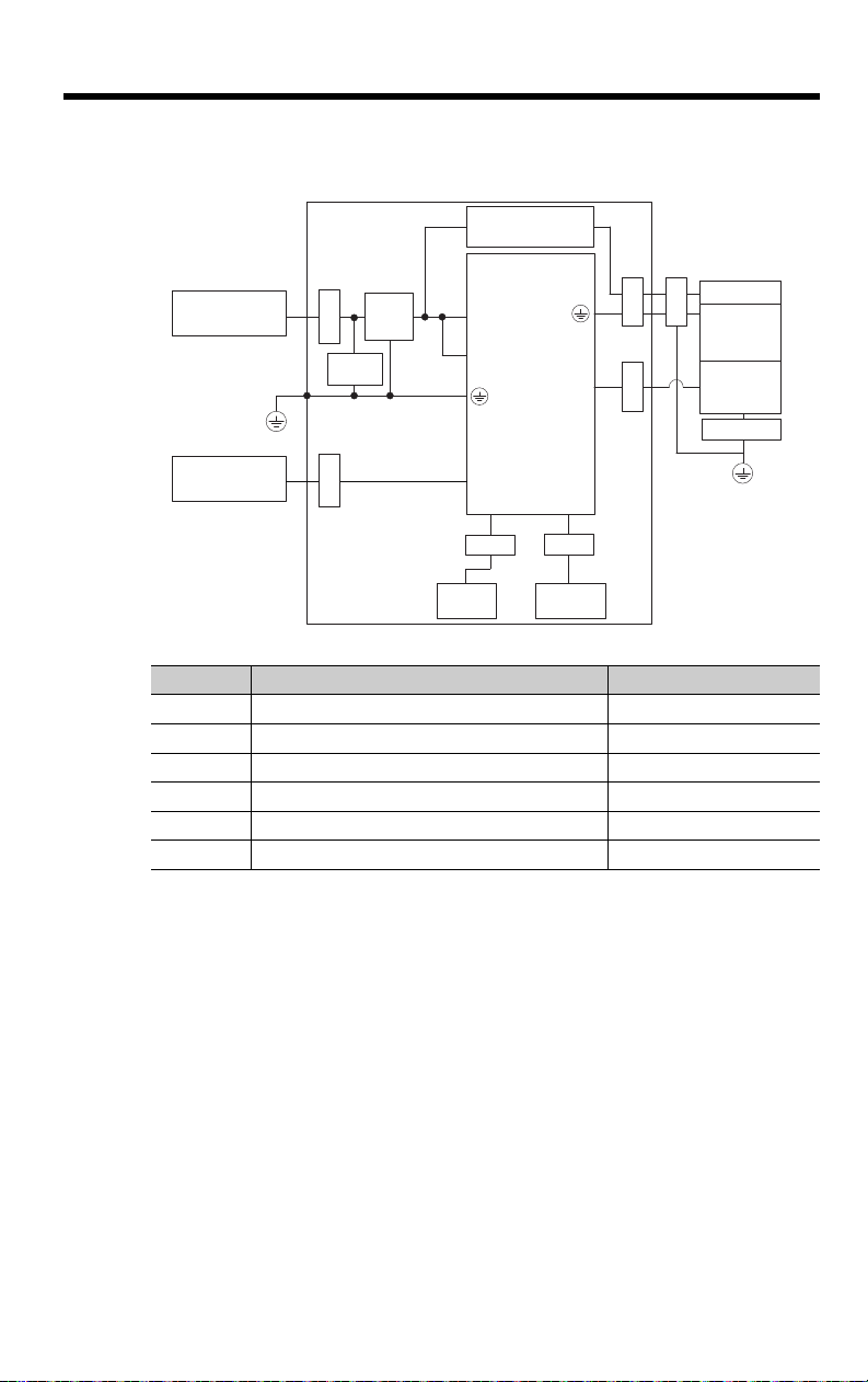
8
CN2
CN6A and CN6B
L1, L2, and L3
U, V, and W
Noise
Filter
Surge
Absorber
Clamp
Brake
Servomotor
Encoder
Brake power supply
SERVOPACK
Safety
function device
I/O
controller
PE
PE
Shield box
Power supply:
Three-phase, 400 VAC
ClampClamp
Clamp
Clamp
Clamp
Clamp
Host controller
Clamp
CN1
24 V, 0 V
Power supply:
24 VDC
CN8
EMC Installation Conditions
• Three-Phase, 400 VAC
Symbol Cable Name Specification
I/O Signal Cable Shielded cable
Safety Function Device Cable Shielded cable
Servomotor Main Circuit Cable Shielded cable
Encoder Cable Shielded cable
Main Circuit Power Supply Cable Shielded cable
Ethernet Communications Cable Shielded cable
42
Page 49

9 Safety
9.1 Safety Modules
The Sigma-7Siec can support safety functions in combination with the
following Safety Module for Σ-V Series, Large-Capacity Σ-V Series, and
Σ-7 Series SERVOPACKs:
• “SGDV-OSA01A” for 200V Sigma-7Siec
• “SGDV-OSA01A000FT900” for 400V Sigma-7Siec
9.2 Safety Module Installation
For the installation procedure of SGDV-OSA01A, please refer to the Σ-V
Series/ Σ-V Series for Large-Capacity Models/ Σ-7 Series Safety
Module Installation Guide (document number TOBPC72082906)
For the installation procedure of SGDV-OSA01A000FT900, please refer
to the Σ-V Series AC SERVOPACK Safety Module with FT900
Specification Installation Guide (document number TOBPC72082909)
9
Safety
9.3 Supported Safety Functions
The Sigma-7Siec on its own supports Hard Wire Base Block (HWBB)
Safety function. For more information on HWBB, please see section 11
in Σ-7S SERVOPACK with EtherCAT (CoE) Communications Reference
Product Manual (document number SIEPS80000155).
The Sigma-7Siec also supports other safety functions in combination
with the safety modules mentioned above. For more details, please see
section 6 in the Safety Module for Σ-V Series, Large-Capacity Σ-V
Series, and Σ-7 Series SERVOPACKs User’s Manual (document
number SIEPC72082906).
9.4 Relationship with Function Blocks for Motion
If the Sigma-7Siec changes to the HWBB state during operation due to
motion commanded by function blocks, a “4400h: Hard Wire Base
Block” error will occur.
If this error occurs, user can turn off “Enable” input of MC_Power
function block, turn on the /HWBB1 and /HWBB2 signals (Safety
request input signals in case of SBB) and turn on “Enable” input of
MC_Power function block. After completing these steps, the HWBB
error will be cleared and operation can resume.
43
Page 50

9
Safety
9.5 Risk Assessment
When using the Safety Module, be sure to perform risk assessment of
the servo system in advance. Make sure that the safety level of the
standards is met. For details about the standards, refer to front of this
manual.
The following residual risks can be present even when the safety
functions operate. Therefore, safety must always be given consideration
during risk assessment.
• If external forces (such as gravitational force with a vertical axis) are applied
when the safety functions of the Safety Module are operating, the motor will
rotate due to the action of these external forces. Provide a separate
mechanical brake to secure the motor.
• If the SERVOPACK fails, the motor may operate within a range of 180
electrical degrees. Make sure that safety is ensured even in hazardous
situations.
• The number of rotations and movement distance for each type of motor are
listed below.
• Rotational Servomotor: 1/6 rotation max. (Rotation angle at motor shaft
conversion)
• Direct Drive Motor: 1/20 rotation max. (Rotation angle at motor shaft
conversion)
• Linear Servomotor: 30 mm max.
44
Page 51

Page 52

IRUMA BUSINESS CENTER (SOLUTION CENTER)
480, Kamifujisawa, Iruma, Saitama, 358-8555, Japan
Phone: 81-4-2962-5696 Fax: 81-4-2962-6138
YASKAWA ELECTRIC CORPORATION
New Pier Takeshiba South Tower, 1-16-1, Kaigan, Minatoku, Tokyo, 105-6891, Japan
Phone: 81-3-5402-4511 Fax: 81-3-5402-4580
http://www.yaskawa.co.jp
YASKAWA AMERICA, INC.
2121 Norman Drive South, Waukegan, IL 60085, U.S.A.
Phone: (800) YASKAWA (800-927-5292) or 1-847-887-7000 Fax: 1-847-887-7310
http://www.yaskawa.com
YASKAWA ELÉTRICO DO BRASIL, LTDA.
Avenida Piraporinha 777, Diadema, São Paulo, 09950-000, Brasil
Phone: 55-11-3585-1100 Fax: 55-11-3585-1187
http://www.yaskawa.com.br
YASKAWA ELECTRIC EUROPE GmbH
Hauptstrae 185, 65760 Eschborn, Germany
Phone: 49-6196-569-300 Fax: 49-6196-569-398
YASKAWA ELECTRIC UK LTD.
1 Hunt Hill Orchardton Woods, Cumbernauld, G68 9LF, United Kingdom
Phone: 44-1236-735000
YASKAWA ELECTRIC KOREA CORPORATION
7F, Doore Bldg. 24, Yeoido-dong, Youngdungpo-Ku, Seoul, 150-877, Korea
Phone: 82-2-784-7844
YASKAWA ELECTRIC (SINGAPORE) PTE. LTD.
151 Lorong Chuan, #04-01, New Tech Park, 556741, Singapore
Phone: 65-6282-3003
YASKAWA ELECTRIC (SHANGHAI) CO., LTD.
No. 18 Xizang Zhong Road, Room 1702-1707, Harbour Ring Plaza, Shanghai, 200001, China
Phone: 86-21-5385-2200
YASKAWA ELECTRIC (SHANGHAI) CO., LTD. BEIJING OFFICE
Room 1011A, Tower W3 Oriental Plaza, No. 1 East Chang An Ave.,
Dong Cheng District, Beijing, 100738, China
Phone: 86-10-8518-4086
YASKAWA ELECTRIC TAIWAN CORPORATION
9F, 16, Nanking E. Rd., Sec. 3, Taipei, Taiwan
Phone: 886-2-2502-5003
Fax: 44-1236-458182
Fax: 82-2-784-8495
Fax: 65-6289-3003
Fax: 86-21-5385-3299
Fax: 86-10-8518-4082
Fax: 886-2-2505-1280
MANUAL NO.
Published in U.S.A
IG.S7Siec.01, Rev C-5
September 10, 2020
 Loading...