

Page 1

YASKAWA AC Drive 1000-Series Option
MECHATROLINK-III
Technical Manual
Type: SI-ET3
To properly use the product, read this manual thoroughly and retain
for easy reference, inspection, and maintenance. Ensure the end user
receives this manual.
MANUAL NO. SIEP C730600 62B
Page 2

Copyright © 2013 YASKAWA ELECTRIC CORPORATION
All rights reserved. No part of this publication may be reproduced, stored in a retrieval system, or transmitted, in any form or by any
means, mechanical, electronic, photocopying, recording, or otherwise, without the prior written permission of Yaskawa. No patent
liability is assumed with respect to the use of the information contained herein. Moreover, because Yaskawa is constantly striving to
improve its high-quality products, the information contained in this manual is subject to change without notice. Every precaution has
been taken in the preparation of this manual. Yaskawa assumes no responsibility for errors or omissions. Neither is any liability
assumed for damages resulting from the use of the information contained in this publication.
2 YASKAWA ELECTRIC SIEP C730600 62B 1000-Series Option SI-ET3 Technical Manual
Page 3

Table of Contents
1 PREFACE AND SAFETY . . . . . . . . . . . . . . . . . . . . . . . . . . . . . . . . . . . . . . . . . . . . . . . 4
2 PRODUCT OVERVIEW . . . . . . . . . . . . . . . . . . . . . . . . . . . . . . . . . . . . . . . . . . . . . . . . 6
3 RECEIVING . . . . . . . . . . . . . . . . . . . . . . . . . . . . . . . . . . . . . . . . . . . . . . . . . . . . . . . . . 7
4 OPTION COMPONENTS . . . . . . . . . . . . . . . . . . . . . . . . . . . . . . . . . . . . . . . . . . . . . . . 8
5 INSTALLATION PROCEDURE . . . . . . . . . . . . . . . . . . . . . . . . . . . . . . . . . . . . . . . . . 10
6 RELATED DRIVE PARAMETERS . . . . . . . . . . . . . . . . . . . . . . . . . . . . . . . . . . . . . . . 17
7 TRANSMISSION INTERFACE . . . . . . . . . . . . . . . . . . . . . . . . . . . . . . . . . . . . . . . . . . 19
8 MECHATROLINK-III COMMANDS . . . . . . . . . . . . . . . . . . . . . . . . . . . . . . . . . . . . . . 24
9 MAIN COMMAND. . . . . . . . . . . . . . . . . . . . . . . . . . . . . . . . . . . . . . . . . . . . . . . . . . . . 26
10 SUB-COMMANDS . . . . . . . . . . . . . . . . . . . . . . . . . . . . . . . . . . . . . . . . . . . . . . . . . . . 39
11 TROUBLESHOOTING . . . . . . . . . . . . . . . . . . . . . . . . . . . . . . . . . . . . . . . . . . . . . . . . 44
12 SPECIFICATIONS . . . . . . . . . . . . . . . . . . . . . . . . . . . . . . . . . . . . . . . . . . . . . . . . . . . 47
YASKAWA ELECTRIC SIEP C730600 62B 1000-Series Option SI-ET3 Technical Manual 3
Page 4
1 Preface and Safety
1 Preface and Safety
Yaskawa manufactures products used as components in a wide variety of industrial systems and equipment. The selection
and application of Yaskawa products remain the responsibility of the equipment manufacturer or end user. Yaskawa
accepts no responsibility for the way its products are incorporated into the final system design. Under no circumstances
should any Yaskawa product be incorporated into any product or design as the exclusive or sole safety control. Without
exception, all controls should be designed to detect faults dynamically and fail safely under all circumstances. All
systems or equipment designed to incorporate a product manufactured by Yaskawa must be supplied to the end user with
appropriate warnings and instructions as to the safe use and operation of that part. Any warnings provided by Yaskawa
must be promptly provided to the end user. Yaskawa offers an express warranty only as to the quality of its products in
conforming to standards and specifications published in the Yaskawa manual. NO OTHER WARRANTY, EXPRESS OR
IMPLIED, IS OFFERED. Yaskawa assumes no liability for any personal injury, property damage, losses, or claims
arising from misapplication of its products.
Applicable Documentation
The following manuals are available for the SI-ET3 option:
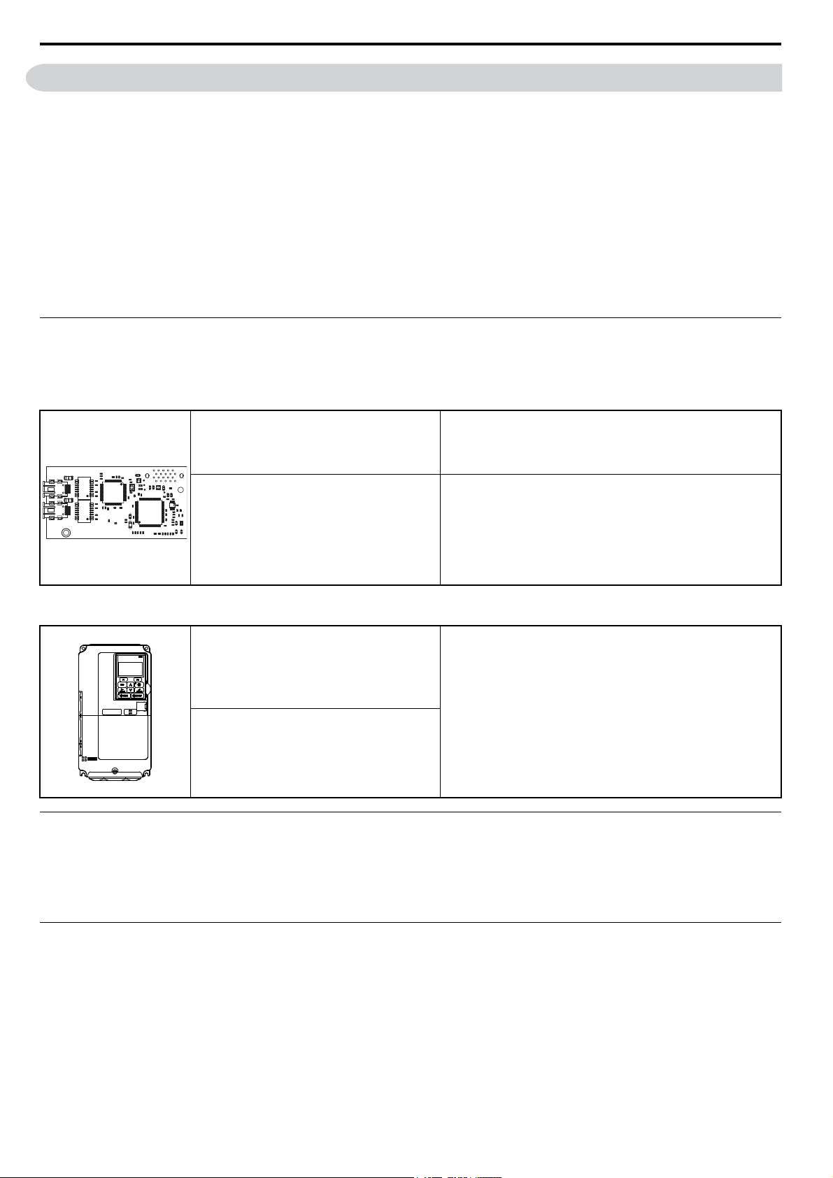
SI-ET3 Option
YASKAWA AC Drive 1000-Series Option
SI-ET3 MECHATROLINK-III
Installation Manual
Manual No: TOBP C730600 62
YASKAWA AC Drive 1000-Series Option
SI-ET3 MECHATROLINK-III
Technical Manual
Manual No: SIEP C730600 62
(This book)
Read this manual first.
The installation manual is packaged with the option and contains
information required to install the option and set up related drive
parameters.
The technical manual contains detailed information about the
option. Access the following sites to obtain the technical manual:
U.S.: http://www.yaskawa.com
Europe: http://www.yaskawa.eu.com
Japan: http://www.e-mechatronics.com
For questions, contact your local Yaskawa sales office or the
nearest Yaskawa representative.
Drive
The drive manuals cover basic installation, wiring, operation
YASKAWA AC Drive
1000-Series Quick Start Guide
YASKAWA AC Drive
1000-Series Technical Manual
procedures, functions, troubleshooting, and maintenance
information.
The manuals also include important information about parameter
settings and drive tuning.
Access these sites to obtain Yaskawa instruction manuals:
U.S.: http://www.yaskawa.com
Europe: http://www.yaskawa.eu.com
Japan: http://www.e-mechatronics.com
For questions, contact your local Yaskawa sales office or the
nearest Yaskawa representative.
Terms
Note: Indicates supplemental information that is not related to safety messages.
Drive: YASKAWA AC Drive 1000-Series
Option: YASKAWA AC Drive 1000-Series Option SI-ET3 MECHATROLINK-III
Registered Trademarks
• MECHATROLINK-III is a trademark of the MECHATROLINK Members Association (MMA).
• All trademarks are the property of their respective owners.
4 YASKAWA ELECTRIC SIEP C730600 62B 1000-Series Option SI-ET3 Technical Manual
Page 5
1 Preface and Safety
DANGER
W ARNING
CAUTION
NOTICE
DANGER
NOTICE
Supplemental Safety Information
Read and understand this manual before installing, operating, or servicing this option. The option must be installed
according to this manual and local codes.
The following conventions are used to indicate safety messages in this manual. Failure to heed these messages could
result in serious or possibly even fatal injury or damage to the products or to related equipment and systems.
Indicates a hazardous situation, which, if not avoided, will result in death or serious injury.
Indicates a hazardous situation, which, if not avoided, could result in death or serious injury.
Indicates a hazardous situation, which, if not avoided, could result in minor or moderate injury.
Indicates an equipment damage message.
General Safety
General Precautions
• The diagrams in this section may include options and drives without covers or safety shields to illustrate details. Be
sure to reinstall covers or shields before operating any devices. The option should be used according to the instructions
described in this manual.
• Any illustrations, photographs, or examples used in this manual are provided as examples only and may not apply to
all products to which this manual is applicable.
• The products and specifications described in this manual or the content and presentation of the manual may be
changed without notice to improve the product and/or the manual.
• When ordering new copies of the manual, contact a Yaskawa representative or the nearest Yaskawa sales office and
provide the manual number shown on the front cover.
Heed the safety messages in this manual.
Failure to comply will result in death or serious injury.
The operator is responsible for injuries or equipment damage caused from failure to heed the warnings in the manual.
Do not modify the drive or option circuitry.
Failure to comply could result in damage to the drive or option and will void warranty.
Yaskawa is not responsible for any modification of the product made by the user. This product must not be modified.
Do not expose the drive or the option to halogen group disinfectants.
Failure to comply may cause damage to the electrical components in the option.
Do not pack the drive in wooden materials that have been fumigated or sterilized.
Do not sterilize the entire package after the product is packed.
YASKAWA ELECTRIC SIEP C730600 62B 1000-Series Option SI-ET3 Technical Manual 5
Page 6

2 Product Overview
2 Product Overview
About This Product
The option provides a communications connection between the drive and a MECHATROLINK-III network. The option
connects the drive to a MECHATROLINK-III network and facilitates the exchange of data.
This manual explains the handling, installation and specifications of this product.
MECHATROLINK-III is a communications link to connect industrial devices (such as smart motor controllers, operator
interfaces, and variable frequency drives) as well as control devices (such as programmable controllers and computers) to
a network. MECHATROLINK-III is a simple, networking solution that reduces the cost and time to wire and install
factory automation devices, while providing interchangeability of like components from multiple vendors.
By installing the option to a drive, it is possible to do the following from a MECHATROLINK-III master device:
• operate the drive
• monitor the operation status of the drive
• change parameter settings
Applicable Models
The option can be used with the drive models in Tabl e 1.
Table 1 Applicable Models
Drive Series Drive Model Number Software Version <1>
CIMR-A2A ≥1020
A1000
<1> See “PRG” on the drive nameplate for the software version number.
CIMR-A4A0002 to 4A0675 ≥1020
CIMR-A4A0930 and 4A1200 Under development
CIMR-A5A ≥1020
6 YASKAWA ELECTRIC SIEP C730600 62B 1000-Series Option SI-ET3 Technical Manual
Page 7
3 Receiving
R/E LK1
CON LK2
3 Receiving
Please perform the following tasks upon receipt of the option:
• Inspect the option for damage. Contact the shipper immediately if the option appears damaged upon receipt.
• Verify receipt of the correct model by checking the model number printed on the name plate of the option package.
• Contact your supplier if you have received the wrong model or the option does not function properly.
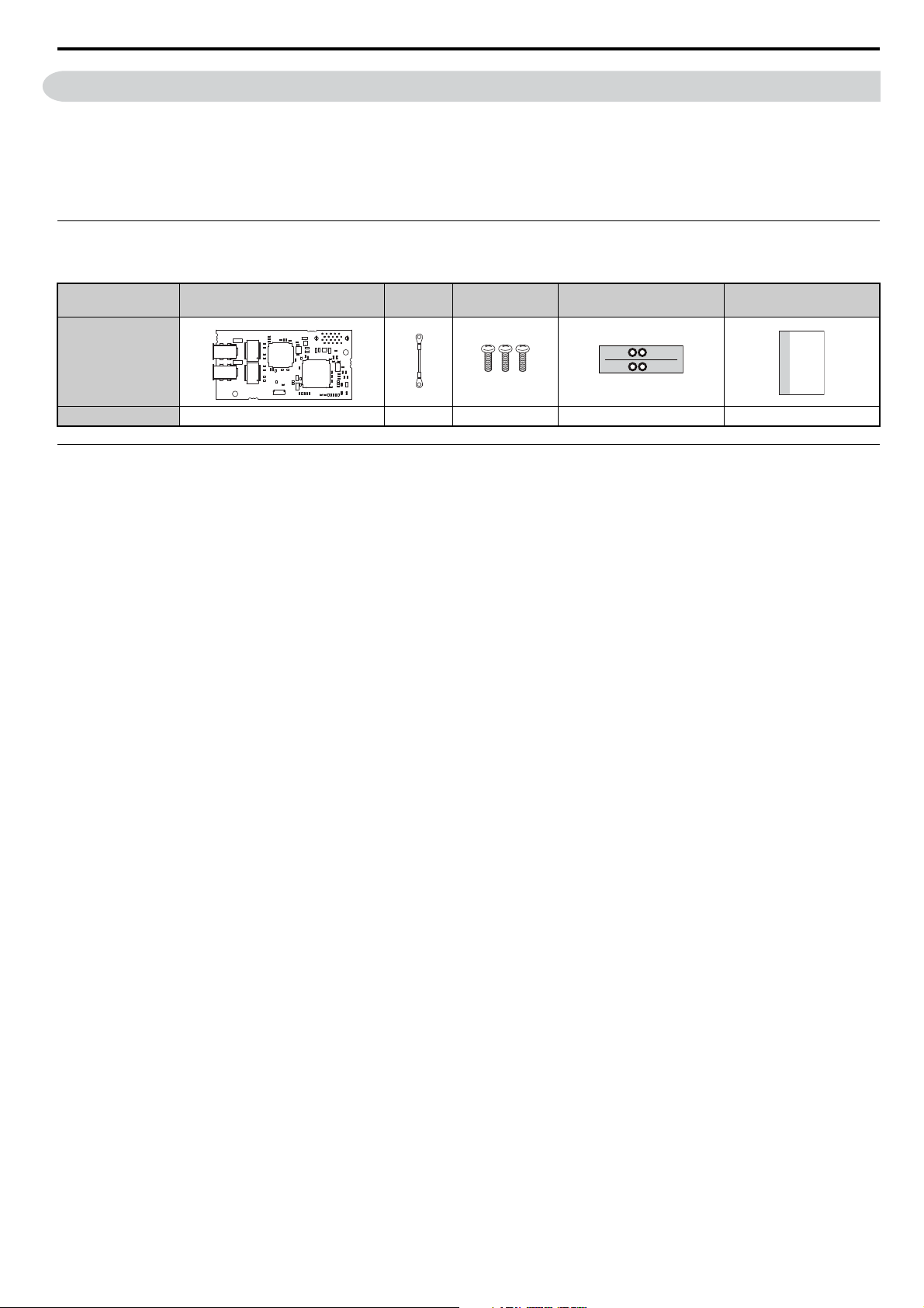
Option Package Components
Table 2 Option Package Contents
Description: Option
_
Quantity: 1131 1
Ground
Wire
Screws (M3) LED Label Installation Manual
MANUAL
Tools Required for Installation
• A Phillips screwdriver (M3 metric/#1, #2 U.S. standard size <1>) is required to install the option and remove drive front
covers.
• Diagonal cutting pliers. (required for some drive models)
• A small file or medium grit sandpaper. (required for certain drive models)
<1> Screw sizes vary by drive capacity. Select a screwdriver appropriate for the drive capacity.
Note: Tools required to prepare option networking cables for wiring are not listed in this manual.
YASKAWA ELECTRIC SIEP C730600 62B 1000-Series Option SI-ET3 Technical Manual 7
Page 8
4 Option Components
A1000
E
F
G
H
I
D
C
B
Underside
A
A1000
4 Option Components
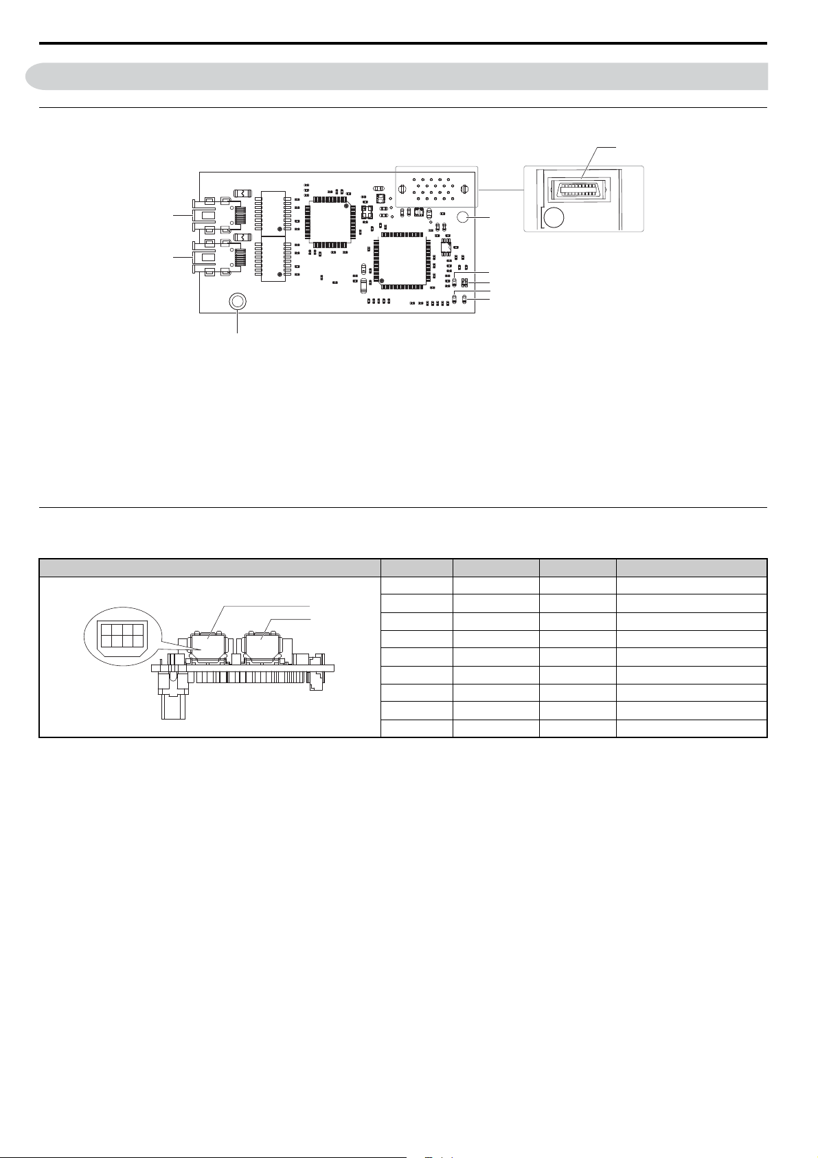
SI-ET3 Option
Figure 1
A – Connector (CN5)
F – LED (LK1) <1>
B – Installation hole G – Ground terminal and installation hole <2>
C–LED (CON)<1> H – Communication connector CN1
D–LED (R/E)
E – LED (LK2)
<1> I – Communication connector CN2
<1>
<1> Refer to Option LED Display on page 9 for details on the LEDs
<2> The ground wire provided in the option shipping package must be connected during installation
Figure 1 SI-EN3 Option Components
Connector
Table 3 Communication Connector
MECHATROLINK-III Connector Pin No. Signal Name I/O Function
1 TXD_P I/O Send data (+): OUT
CN2
CN1
2468
1357
2 TXD_N I/O Send data (-): OUT
3 RXD_P I/O Receive data (-): IN
4(NC) – –
5(NC) – –
6 RXD_N I/O Receive data (-): IN
7(NC) – –
8(NC) – –
Shell SLD – Shield
8 YASKAWA ELECTRIC SIEP C730600 62B 1000-Series Option SI-ET3 Technical Manual
Page 9

4 Option Components
Option LED Display
The MECHATROLINK-III Option has four LEDs that indicate the option card or communication status.
Checking LED Operation
Table 4 Option LED States
Name Display Operating Status Remarks
R/E
CON
LK1
LK2
Lit in
green
Lit in red Error
Flashing in
red
Unlit Power supply off
Lit in
green
Unlit Connection unestablished Connection with master device is not established
Lit in
green
Unlit
Lit in
green
Unlit
Power supply on
SI-ET3 error Error found during SI-ET3’s self-diagnostic check
Connection established Established connection
Connector CN1 connected Connector CN1 is connected to other stations
Connector CN1
disconnected
Connector CN2 connected Connector CN2 is connected to other stations
Connector CN2
disconnected
• SI-ET3 has been successfully powered up
• An internal, self-diagnostic check completed in the SI-ET3
• Error/alarm occured
• Command error occurred (parameter error, phase error, combination error)
• The drive has no power
• SI-ET3 is not properly connected to the drive, or SI-ET3 has no power
• An internal, self-diagnostic error occurred in the SI-ET3
Connector CN1 is not connected to other stations (cable not connected, cable
disconnected, other stations not powered up)
Connector CN2 is not connected to other stations (cable not connected, cable
disconnected, other stations not powered up)
YASKAWA ELECTRIC SIEP C730600 62B 1000-Series Option SI-ET3 Technical Manual 9
Page 10

5 Installation Procedure
DANGER
W ARNING
NOTICE
5 Installation Procedure
Section Safety
Electrical Shock Hazard
Do not connect or disconnect wiring while the power is on.
Failure to comply will result in death or serious injury.
Disconnect all power to the drive and wait at least the amount of time specified on the drive front cover safety label.
After all indicators are off, measure the DC bus voltage to confirm safe level, and check for unsafe voltages before
servicing. The internal capacitor remains charged after the power supply is turned off.
Electrical Shock Hazard
Do not remove the front covers of the drive while the power is on.
Failure to comply could result in death or serious injury.
The diagrams in this section may include options and drives without covers or safety shields to show details. Be sure to
reinstall covers or shields before operating any devices. The option should be used according to the instructions
described in this manual.
Do not allow unqualified personnel to use equipment.
Failure to comply could result in death or serious injury.
Maintenance, inspection, and replacement of parts must be performed only by authorized personnel familiar with
installation, adjustment, and maintenance of this product.
Do not touch circuit boards while the power to the drive is on.
Failure to comply could result in death or serious injury.
Do not use damaged wires, place excessive stress on wiring, or damage the wire insulation.
Failure to comply could result in death or serious injury.
Fire Hazard
Tighten all terminal screws to the specified tightening torque.
Loose electrical connections could result in death or serious injury by fire due to overheating of electrical connections.
Damage to Equipment
Observe proper electrostatic discharge (ESD) procedures when handling the option, drive, and circuit boards.
Failure to comply may result in ESD damage to circuitry.
Never shut the power off while the drive is outputting voltage.
Failure to comply may cause the application to operate incorrectly or damage the drive.
Do not operate damaged equipment.
Failure to comply may cause further damage to the equipment.
Do not connect or operate any equipment with visible damage or missing parts.
Do not use unshielded cable for control wiring.
Failure to comply may cause electrical interference resulting in poor system performance.
Use shielded twisted-pair wires and ground the shield to the ground terminal of the drive.
10 YASKAWA ELECTRIC SIEP C730600 62B 1000-Series Option SI-ET3 Technical Manual
Page 11
5 Installation Procedure
NOTICE
A1000
Properly connect all pins and connectors.
Failure to comply may prevent proper operation and possibly damage equipment.
Check wiring to ensure that all connections are correct after installing the option and connecting any other
devices.
Failure to comply may result in damage to the option.
Prior to Installing the Option
Prior to installing the option, wire the drive, make necessary connections to the drive terminals, and verify that the drive
functions normally without the option installed. Refer to the instruction manual packaged with the drive for information
on wiring and connecting the drive.
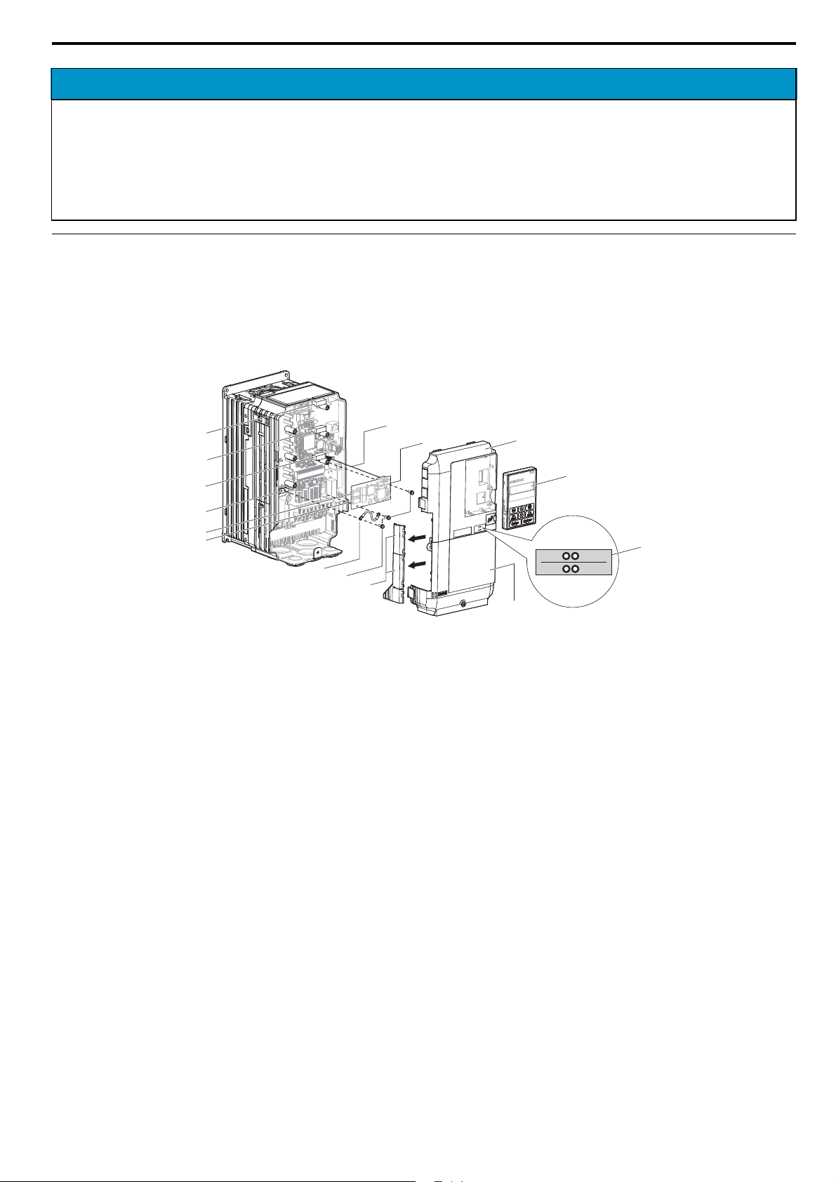
Figure 2 shows an exploded view of the drive with the option and related components for reference.
Figure 2
O
N
M
L
K
J
I
H
A
B
G
C
D
R/E
LK1
CON
LK2
F
E
A – Insertion point for CN5 connector I – Ground wire
B – SI-ET3 option J – Option modular connector CN1
C – Drive front cover K – Option modular connector CN2
D – Digital operator L – Drive grounding terminal (FE)
E – LED label M – Connector CN5-A
F – Drive terminal cover N – Connector CN5-B
G – Removable tabs for wire routing O – Connector CN5-C
H – Included screws
Figure 2 Drive Components with Option
YASKAWA ELECTRIC SIEP C730600 62B 1000-Series Option SI-ET3 Technical Manual 11
Page 12
5 Installation Procedure
C
D
F
A1000
A1000
Installing the Option
Remove the front covers of the drive before installing the option. Refer to the drive instruction manual for directions on
removing the front covers. Cover removal varies depending on drive size. This option can be inserted only into the
CN5-A connector located on the drive control board.
DANGER! Electrical Shock Hazard. Do not connect or disconnect wiring while the power is on. Failure to comply could result in death
or serious injury. Before installing the option, disconnect all power to the drive and wait at least the amount of time specified on the
drive front cover safety label. After all indicators are off, measure the DC bus voltage to confirm safe level, and check for unsafe
voltages before servicing. The internal capacitor remains charged after the power supply is turned off.
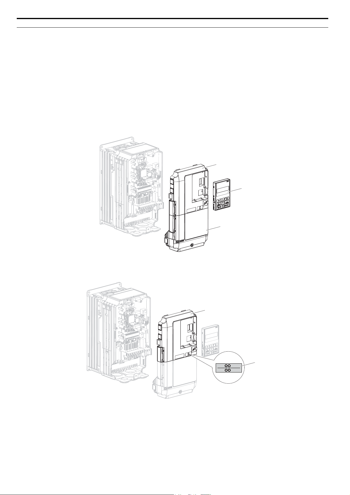
1. Shut off power to the drive, wait the appropriate amount of time for voltage to dissipate, then remove the digital
operator (D) and front covers (C, F). Cover removal varies depending on drive size.
NOTICE: Damage to Equipment. Observe proper electrostatic discharge procedures (ESD) when handling the option, drive, and
circuit boards. Failure to comply may result in ESD damage to circuitry.
Figure 3
Figure 3 Remove the Front Covers and Digital Operator
2. With the front covers and digital operator removed, apply the LED label (E) in the appropriate position on the
Figure 4
drive top front cover (C).
Figure 4 Apply the LED Label
C
R/E LK1
CON LK2
E
12 YASKAWA ELECTRIC SIEP C730600 62B 1000-Series Option SI-ET3 Technical Manual
Page 13
5 Installation Procedure
NS
MS
M
H
B
A1000
NS MS
H
I
L
B
A1000
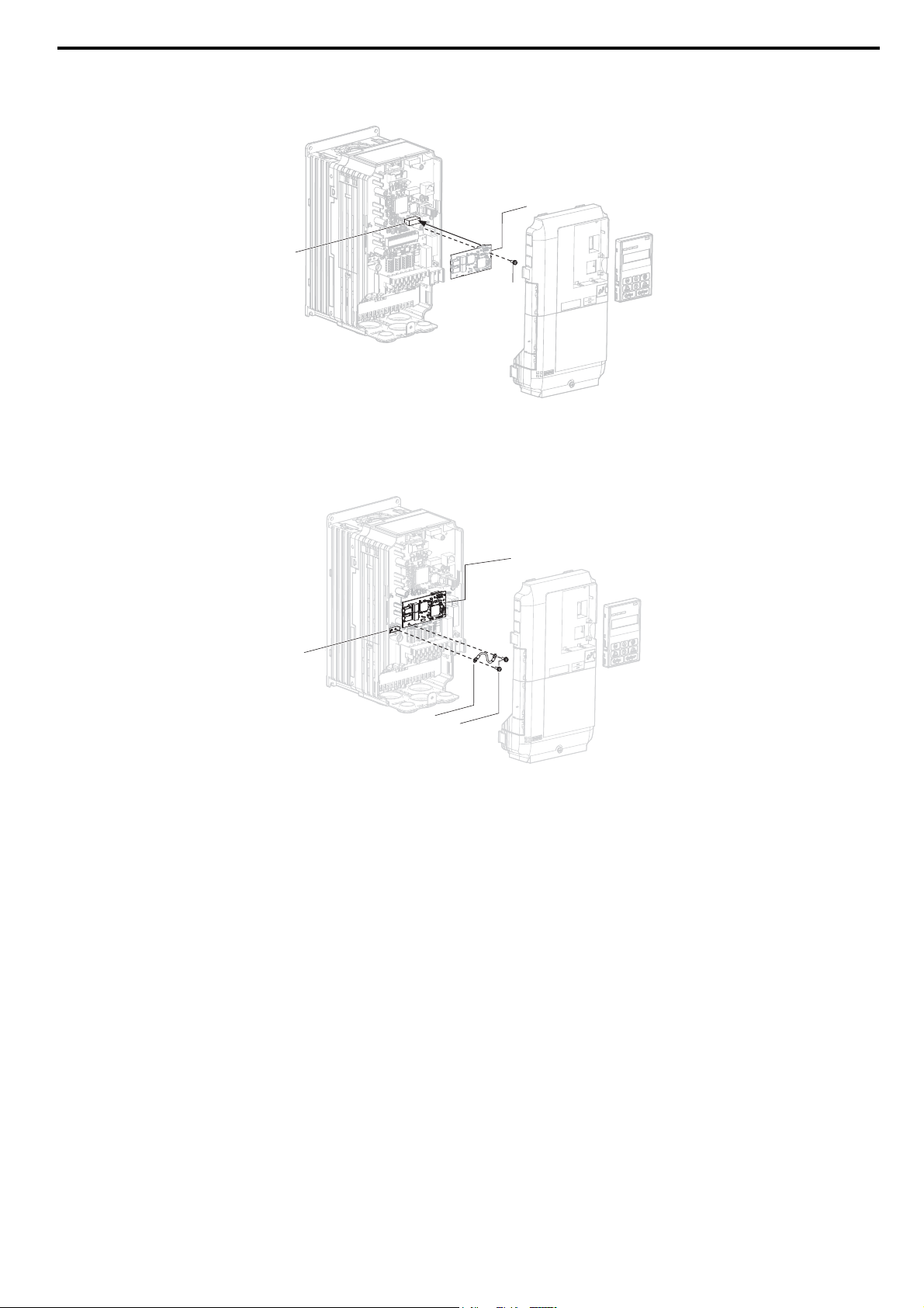
3. Insert the option (B) into the CN5-A connector (M) located on the drive and fasten it using one of the included
Figure 5
screws (H).
Figure 5 Insert the Option
4. Connect the ground wire (I) to the ground terminal (L) using one of the remaining provided screws (H). Connect
the other end of the ground wire (I) to the remaining ground terminal and installation hole on the option (B) using
Figure 6
the last remaining provided screw (H) and tighten both screws to 0.5 to 0.6 Nxm (4.4 to 5.3 in lbs).
Figure 6 Connect the Ground Wire
Note: There are two screw holes on the drive for use as ground terminals (L). When connecting three options, two ground wires will
need to share the same drive ground terminal.
YASKAWA ELECTRIC SIEP C730600 62B 1000-Series Option SI-ET3 Technical Manual 13
Page 14
5 Installation Procedure
B
A
A1000
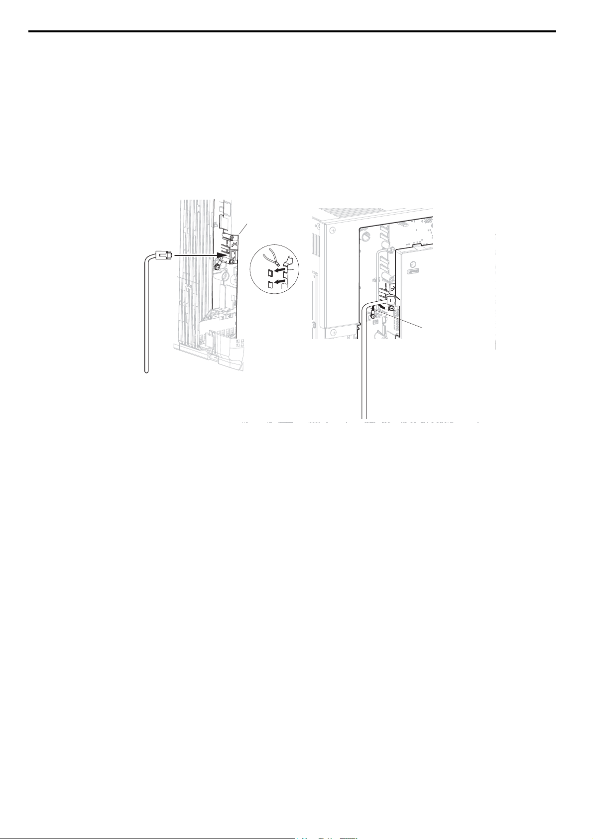
5. Route the option wiring.
Depending on the drive model, some drives may require routing the wiring through the side of the front cover to
the outside to provide adequate space for the wiring. Refer to the Peripheral Devices & Options section of the
drive Quick Start Guide or instruction manual for more information on wire routing of specific models.
Route the wiring through the side of the front cover to the outside. In these cases, using diagonal cutting pliers,
cut out the perforated openings on the left side of the drive front cover as shown in Figure 7-A. Sharp edges
along the cut out should be smoothed down with a file or sand paper to prevent any damage to the wires.
Route the wiring inside the enclosure as shown in Figure 7-B for drives that do not require routing through the
front cover.
Note: Separate communication cables from main circuit wiring and other electrical lines.
Figure 7
A – Route wires through the openings
provided on the left side of the
front cover.
<1> The drive will not meet NEMA Type 1 requirements if wiring is exposed outside the enclosure.
<1>
Figure 7 Wire Routing Examples
B – Use the open space provided
inside the drive to route option
wiring.
6. Connect the MECHATROLINK-III communication cable to option communication connector CN1 or CN2. Refer
to Communication Cable Wiring on page 15 for details.
Install MECHATROLINK-III communications cables apart from main-circuit wiring and other electrical and power
lines. Ensure the cable end is firmly connected (see Figure 7).
Note: Maximum transmission distance is 100 m (3937.0 in.). Minimum wiring distance between stations is 0.2 m (7.9 in.).
14 YASKAWA ELECTRIC SIEP C730600 62B 1000-Series Option SI-ET3 Technical Manual
Page 15
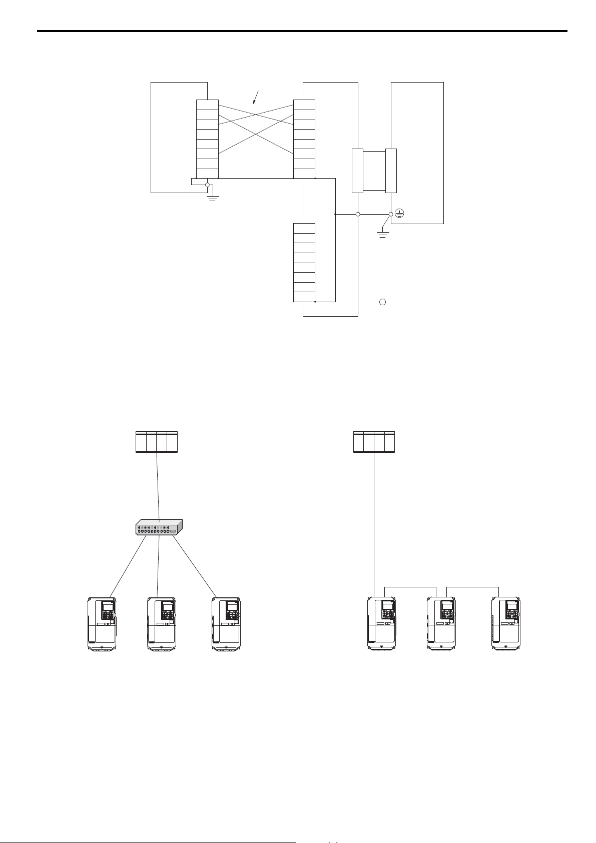
Connection Diagram
A1000
PLC
MECHATROLINK-III
Hub Module
A1000 A1000 A1000
A1000 A1000 A1000
PLC
A1000
MECHATROLINK-III
Master
TXD_P
TXD_N
RXD_P
NC
NC
RXD_N
NC
NC
MECHATROLINK-III
Communication Cable
TXD_P
TXD_N
RXD_P
NC
NC
RXD_N
NC
NC
TXD_P
TXD_N
RXD_P
NC
NC
RXD_N
NC
NC
CN2
CN1
SI-ET3
<1>
<1>
5 Installation Procedure
Drive
FE
control circuit terminal
Figure 8
<1> Use connector CN1 or CN2 to connect with the MECHATROLINK-III master. Refer to Communication Cable Wiring on
page 15 for details.
Figure 8 Option Connection Diagram
Communication Cable Wiring
The dual communication cable ports on the option board act as a switch to allow for flexibility in cabling topology.
For example, a traditional star network topology may be employed by using a single port on the option board.
Alternatively, a daisychained approach may be employed by using both communication cable ports. This second
approach reduces the requirements of MECHATROLINK-III hub module ports.
YASKAWA ELECTRIC SIEP C730600 62B 1000-Series Option SI-ET3 Technical Manual 15
Figure 9 Topology Options
Page 16

5 Installation Procedure
L
Wind the cable one turn
around the ferrite core.
A1000
Table 5 MECHATROLINK-III Communication Cable
Connection Type Cable Specification Length (L) Model
0.2 m (7.9 in.) JEPMC-W6012-A2-E
0.5 m (19.7 in.) JEPMC-W6012-A5-E
1 m (39.4 in.) JEPMC-W6012-01-E
2 m (78.7 in.) JEPMC-W6012-02-E
MECHATROLINK-III
connection without
ferrite core
MECHATROLINK-III
connection with
ferrite core
MECHATROLINK-III
connection with loose
wires at one end
L
L
3 m (118.1 in.) JEPMC-W6012-03-E
4 m (157.5 in.) JEPMC-W6012-04-E
5 m (196.9 in.) JEPMC-W6012-05-E
10 m (393.7 in.) JEPMC-W6012-10-E
20 m (787.4 in.) JEPMC-W6012-20-E
30 m (1181.1 in.) JEPMC-W6012-30-E
50 m (1968.5 in.) JEPMC-W6012-50-E
10 m (393.7 in.) JEPMC-W6013-10-E
20 m (787.4 in.) JEPMC-W6013-20-E
30 m (1181.1 in.) JEPMC-W6013-30-E
50 m (1968.5 in.) JEPMC-W6013-50-E
75 m (2952.8 in.) JEPMC-W6013-75-E
100 m (3937.0 in.) JEPMC-W6013-100-E
0.5 m (19.7 in.) JEPMC-W6014-A5-E
1 m (39.4 in.) JEPMC-W6014-01-E
3 m (118.1 in.) JEPMC-W6014-03-E
5 m (196.9 in.) JEPMC-W6014-05-E
10 m (393.7 in.) JEPMC-W6014-10-E
30 m (1181.1 in.) JEPMC-W6014-30-E
50 m (1968.5 in.) JEPMC-W6014-50-E
7. Replace and secure the front covers of the drive (C, F) and replace the digital operator (D).
Figure 9
C
D
F
Figure 10 Replace the Front Covers and Digital Operator
Note: Take proper precautions when wiring the option so that the front covers will easily fit back onto the drive. Make sure no cables
are pinched between the front covers and the drive when replacing the covers.
8. Set drive parameters in Table 6 for proper option performance.
16 YASKAWA ELECTRIC SIEP C730600 62B 1000-Series Option SI-ET3 Technical Manual
Page 17

6 Related Drive Parameters
6 Related Drive Parameters
The following parameters are used to set up the drive for operation with the option. Parameter setting instructions can be
found in the drive instruction manual.
Confirm proper setting of the all parameters in Ta bl e 6 using the digital operator before starting network
communications.
Table 6 Related Parameter Settings
No.
(Addr.
Hex)
b1-01
(180)
<1>
b1-02
(181)
<1>
F6-01
(3A2)
F6-02
(3A3)
F6-03
(3A4)
F6-06
(3A7)
<3>
F6-07
(3A8)
F6-08
(36A)
F6-20
<5> <6>
F6-21
<5>
F6-23
<5> <7>
F6-24
<5> <8>
F6-25
Frequency Reference Selection
Run Command Selection
Operation Selection after
Communications Error
External Fault Detection
Conditions (EF0)
Stopping Method for External
Fault from the Communication
Option
Torque Reference/Torque Limit
Selection from the
Communication Option
NetRef/ComRef Selection
Function
Reset Communication Related
Parameters
MECHATROLINK Station
Address
MECHATROLINK Frame Size
MECHATROLINK Monitor
Selection
(Code 0EH)
MECHATROLINK Monitor
Selection
(Code 0FH)
Operation Selection at Watchdog
Error (E5)
Name Description Val ues
Selects the frequency reference input source.
0: Operator - Digital preset speed d1-01 to d1-17
1: Terminals - Analog input terminal A1 or A2
2: MEMOBUS/Modbus communications
3: Option
Default: 1
Range: 0 to 4
(Set to 3)
4: Pulse Input (Terminal RP)
Selects the run command input source.
0: Digital Operator - RUN and STOP keys
1: Digital input terminals S1 to S8
2: MEMOBUS/Modbus communications
Default: 1
Range: 0 to 3
(Set to 3)
3: Option
Determines drive response when a bUS error is detected during
communications with the option.
0: Ramp to Stop
1: Coast to Stop
Default: 1
Range: 0 to 3
2: Fast-Stop
3: Alarm Only
Sets the condition for external fault detection (EF0).
0: Always detected
1: Detected only during operation
<2>
Default: 0
Range: 0, 1
Determines drive response for external fault input (EF0) detection during
option communications.
0: Ramp to Stop
1: Coast to Stop
Default: 1
Range: 0 to 3
2: Fast-Stop
3: Alarm Only
<2>
0: Torque Reference/Torque Limit via network communications are
disabled.
1: Torque Reference/Torque Limit via network communications are
enabled.
<4>
0: Multi-step speed reference disabled (F7 functionality)
1: Multi-step speed reference allowed (V7 functionality)
Default: 0
Range: 0, 1
Default: 0
Range: 0, 1
Determines if communication-related parameters F6- and F7-
are set back to original default values when the drive is initialized using
parameter A1-03.
0: Do not reset parameters
Default: 0
Range: 0, 1
1: Reset parameters
Sets the station number.
Sets the frame size.
0: 64 byte
1: 32 byte
Set MEMOBUS/Modbus register to monitor SEL_MON of INV_CTL
and INV_CTL.
Set MEMOBUS/Modbus register to monitor SEL_MON of INV_CTL
and INV_CTL.
Default: 21H
Range: 20 to 3FH
Default: 0
Range: 0, 1
Default: 0H
Range: 0 to FFFFH
Default: 0H
Range: 0 to FFFFH
0: Ramp to stop. Decelerate to stop using the deceleration time in C1-02.
1: Coast to stop.
2: Fast Stop. Decelerate to stop using the deceleration time in C1-09.
Default: 1
Range: 0 to 3
3: Alarm only.
YASKAWA ELECTRIC SIEP C730600 62B 1000-Series Option SI-ET3 Technical Manual 17
Page 18

6 Related Drive Parameters
No.
(Addr.
Hex)
F6-26
<1> To start and stop the drive with the MECHATROLINK-III master device using serial communications, set b1-02 to 3. To control the frequency
reference of the drive via the master device, set b1-01 to 3.
<2> If set to 3, then the drive will continue to operate when a fault is detected. Take proper measures such as installing an emergency stop switch.
<3> Enabled in CLV, AOLV/PM, and CLV/PM control modes (A1-02 = 3, 6, or 7). When enabled, d5-01 determines whether the value is read as the
Torque Limit value (d5-01 = 0) or read as the Torque Reference value (d5-01 = 1). In CLV/PM, this value is read as the Torque Limit.
<4> The setting specifies that the Torque Reference or Torque Limit is to be provided via network communications (F6-06 = 1). The motor may
rotate if no torque reference or Torque Limit is supplied from the PLC.
<5> Power must be cycled in order for any setting changes to take affect.
<6> All station addresses must be unique. If set to 20 or 3F, a Station Address Error (AEr) will occur and the ERR light will turn on.
<7> Setting byte 10 of INV_CTL to 0EH enables the register set by F6-23. Byte 11 and 12 of the response data enable the register content set by
F6-23. Refer to the drive instruction manual for details on the register that can be set.
<8> Setting byte 10 of INV_CTL to 0FH enables the register set by F6-24. Byte 11 and 12 of the response data enable the register content set by
F6-24. Refer to the drive instruction manual for details on the register that can be set.
MECHATROLINK bUS Errors
Detected
Name Description Value s
Sets the number of option communication errors (bUS).
Default: 2
Range: 2 to 10
18 YASKAWA ELECTRIC SIEP C730600 62B 1000-Series Option SI-ET3 Technical Manual
Page 19

7 Transmission Interface
A1000
7 Transmission Interface
MECHATROLINK-III Cyclic Transmissions
As a MECHATROLINK-III station, the SI-ET3 exchanges control data and I/O data with a control device, such as a
controller. Communications with the master are executed by sending response data timed to the reception of command
data for the local station address from the master in each transmission cycle. The formats for the command and response
data follow the specifications for the MECHATROLINK Drive commands.
Master: MP2300S
Controller (Example)
MP
23
0
0
S
4&;
470
;#5-#9#
470
'44
#./
'44
.-
.-
/6:
$#6
64:
+2
5612
/5
572
1(( 10
+06
59
%0()
/10
6'56
01
10
59
'
+06
'
6'56
01
10
$#66'4;
M-I/II
4.;
176
E
thernet
LINK
&%
8
&%
0V
/
YASKAWA ELECTRIC SIEP C730600 62B 1000-Series Option SI-ET3 Technical Manual 19
Page 20

7 Transmission Interface
Command Format of the Standard Profile Common Commands
This section describes the specifications of the standard profile common commands.
Tab le 7 shows the data format and the list of common commands of the commands and responses.
For standard inverter profile commands, the data length is fixed at 32 bytes for main commands and sub-commands.
Table 7 Command Format of the Standard Profile Common Commands
– Byte Command Response Reference
0 CMD RCMD
1 WDT RWDT
Main Commands
Sub-Commands
2
3
4
5
6
7
8
9
10
11
12
13
14
15
16
17
18
19
20
21
22
23
24
25
26
27
28
29
30
31
32 SUBCMD RSUBCMD
33
35
36
37
38
x
x
59
60
61
CMD_CTRL CMD_STAT
CMD_DATA RSP_DATA
SUB_CTRL SUB_STAT34
SUB_CMD_DATA SUB_RSP_DATA
• CMD/RCMD
Command code specified for individual commands.
Refer to Main Command on page 26.
•WDT/RWDT
Watchdog data is usually set automatically.
•CMD_CTRL
Refer to Command Control (CMD_CTRL) on page 24.
•CMD_STAT
Refer to Command Status (CMD_STAT) on page 24.
• CMD_DATA/RSP_DATA
Specified for individual commands.
Refer to Main Command on page 26.
• SUBCMD/RSUBCMD
Command code specified for individual commands.
Refer to Sub-Commands on page 39.
• SUB_CTRL
Refer to SUB_CTRL (Sub-Command Control Field) on
page 39.
• SUB_STAT
Refer to SUB_STAT (Sub-Command Status) on
page 39.
• SUB_CMD_DATA/SUB_RSP_DATA
Specified for individual commands. Refer to
Sub-Commands on page 39.
20 YASKAWA ELECTRIC SIEP C730600 62B 1000-Series Option SI-ET3 Technical Manual
Page 21

7 Transmission Interface
Communications Phases
The SI-ET3 changes status as described here when a command code or fault is received from the master.
Figure 10
Power ON
Phase 1 (Initial status)
Connecting:
CONNECT command
(Asynchronous communications)
Disconnecting:
DISCONNECT command
Disconnecting:
DISCONNECT command
Phase 2 (Asynchronous communications status)
Set Synchronization
(SYNC_SET command)
Connecting:
CONNECT command
(Synchronous communications)
Communications fault
Watchdog timer fault
Phase 3 (Synchronous communications status)
Figure 11 Communication phases
Phase 1: Initial status after power ON
Operation proceeds with a default transmission cycle of 2 ms. The transmission cycle is changed to the time indicated in
the synchronous frame when a CONNECT command is received from the master. Then the phase moves to phase 2 or
phase 3 after a response to the CONNECT command is returned.
Even if a transfer fault is detected in phase 1, no fault notification is provided.
Phase 2: Asynchronous communications
All SI-ET3 commands can be used. Phase 2 starts to count the watchdog timer in the communications frame. The phase
moves to phase 3 when a SYNC_SET command is received, and it moves to phase 1 when a DISCONNECT command is
received.
YASKAWA ELECTRIC SIEP C730600 62B 1000-Series Option SI-ET3 Technical Manual 21
Page 22

7 Transmission Interface
Phase 3: Synchronous communications
Watchdog timer faults in the communications frame are detected. If the DISCONNECT command is received, the phase
moves to phase 1. If a reception fault or a watchdog timer fault is detected, the phase moves to phase 2.
Available command is determined by communication phases. For details, refer to Ta bl e 8 and Ta bl e 9 .
Table 8 Main Command Communication Phases
Command
NOP 00 No Operation Command – {{
PRM_RD 01 Read Parameter Command – {{
PRM_WR 02 Write Parameter Command – {{
ID_RD 03 Read ID Command – {{
CONFIG 04 Setup Device Command – {{
ALM_RD 05 Read Alarm or Warning Command – {{
ALM_CLR 06 Clear Alarm or Warning Command – {{
SYNC_SET 0D Start Synchronous Communication Command – { Δ
CONNECT 0E Establish Connection Command { ΔΔ
DISCONNECT 0F Release Connection Command {{{
INV_CTL 50 Inverter Operation Control Command – {{
{: Can be executed
Δ: Ignored
–: Cannot be executed (phase error)
Code
[HEX]
Contents
Communication Phase
1 2 3
Table 9 Sub-Command Communication Phases
Command
NOP 00 No Operation Command – {{
PRM_RD 01 Read Parameter Command – {{
PRM_WR 02 Write Parameter Command – {{
ALM_RD 05 Read Alarm or Warning Command – {{
INV_IO 51 Drive I/O Control Command – {{
{: Can be executed
Δ: Ignored
–: Cannot be executed (phase error)
Code
[HEX]
Contents
Communication Phase
1 2 3
22 YASKAWA ELECTRIC SIEP C730600 62B 1000-Series Option SI-ET3 Technical Manual
Page 23

7 Transmission Interface
Application Layer Specifications
The data format for the application layer conforms to the MECHATROLINK-III command specifications for standard
inverter profile.
SI-ET3 has the following main commands and sub-commands.
Table 10 Main Commands
Code
[HEX]
00 NOP No Operation Command
01 PRM_RD Read Parameter Command
02 PRM_WR Write Parameter Command
03 ID_RD Read ID Number Command
04 CONFIG RAM Write and EEPROM Write Command
05 ALM_RD Read Alarm and Warning Command
06 ALM_CLR Clear Alarm and Warning Command
0D SYNC_SET Start Synchronous Communications Command
0E CONNECT Connect Command
0F DISCONNECT Disconnect Command
50 INV_CTL Inverter Operation Control Command
Name Function
Table 11 Sub-Commands
Code
[HEX]
00 NOP No Operation Command
01 PRM_RD Read Parameter Command
02 PRM_WR Write Parameter Command
05 ALM_RD Read Alarm and Warning Command
51 INV_I/O Inverter I/O Control Command
Name Function
The sub-commands can be used only when the 64-byte data transmission (F6-21 = 0) has been selected. If a conflict
occurs between a request for a main command and a request for a sub-command, the request for the main command is
processed. If either a main command or a sub-command is already being processed, the command being processed is
given priority. If an INV_CTL main command and an INV_I/O sub-command conflict, the sub-command is given
priority.
For details on command formats, refer to MECHATROLINK-III Commands on page 24.
Tab le 1 2 shows the combination of main commands and sub-commands.
Table 12 Main Commands and Sub-Commands
Code
[HEX]
00 NOP OK OK OK OK OK
01 PRM_RD OK – – OK OK
02 PRM_WR OK – – OK OK
03 ID_RD OKOKOKOKOK
04 CONFIGOK––––
05 ALM_RDOK––––
06 ALM_CLR OK – – – –
0D SYNC_SET OK OK OK OK OK
0E CONNECT OK – – – –
0F DISCONNECT OK – – – –
50 INV_CTL OKOKOKOKOK
Note: CMD_ALM = BH (sub-command combination error) will result if a main command and sub-command conflict with one
another.
Main Command
NOP (00H) PRM_RD (01H) PRM_WR (02H) ALM_RD (05H) INV_I/O (51H)
Sub-Command
YASKAWA ELECTRIC SIEP C730600 62B 1000-Series Option SI-ET3 Technical Manual 23
Page 24

8 MECHATROLINK-III Commands
8 MECHATROLINK-III Commands
Command Control (CMD_CTRL)
bit 7 bit 6 bit 5 bit 4 bit 3 bit 2 bit 1 bit 0
CMD_ID Reserved (0) Reserved (0) ALM_CLR Reserved (0) Reserved (0) Reserved (0)
bit 15 bit 14 bit 13 bit 12 bit 11 bit 10 bit 9 bit 8
Reserved (0)
Command Description
CMD_ID This is not used with standard inverter profile commands.
0: Clear alarm/warning disabled
ALM_CLR
Command Status (CMD_STAT)
bit 7 bit 6 bit 5 bit 4 bit 3 bit 2 bit 1 bit 0
RCMD_ID Reserved (0) Reserved (0) ALM_CLR_CMP CMDRDY D_WAR D_ALM
bit 15 bit 14 bit 13 bit 12 bit 11 bit 10 bit 9 bit 8
1: Clear alarm/warning triggered
The same processing as when ALM_CLR_MODE = 0 for the ALM_CLR command (the current alarm/warning state is
cleared) is performed.
COMM_ALM CMD_ALM
Command Description
RCMD_ID The slave returns the echo of the CMD_ID as the RCMD_ID.
ALM_CLR_CMP
CMDRDY
D_WAR
D_ALM
COMM_ALM
CMD_ALM
ALM_CLR_CMP = 1 means that CMD_CTRL.ALM_CLR = 1 has been received and alarm clear processing has been
completed.
1: Command reception enabled
0: Other
0: Normal operation
1: The device is in the warning state.
0: Normal operation
1: The device is in the alarm state.
Notifies the communication error state.
COMM_ALM is independent of CMD_ALM, D_ALM and D_WAR.
COMM_ALM is cleared at the leading edge of CMD_CTRL.ALM_CLR or by the ALM_CLR command. Refer to
COMM_ALM on page 24 for details.
Notifies the command error state.
If a normal command is received after the occurrence of a command error, CMD_ALM is automatically cleared. Refer to
COMM_ALM on page 24 for details.
COMM_ALM
Code
[HEX]
–0Normal
1 Frame Check Sequence (FCS) error
Warn in g
Alarm
2 Command data not received
3 Synchronous frame not received
8 Frame Check Sequence (FCS) error
9 Command data not received
A Synchronous frame not received
B Synchronization interval error
CWDT error
Contents
24 YASKAWA ELECTRIC SIEP C730600 62B 1000-Series Option SI-ET3 Technical Manual
Page 25

CMD_ALM
8 MECHATROLINK-III Commands
Code
[HEX]
–0Normal
Warning 1 Invalid data
8 Unsupported command received
9 Invalid data
Alarm
A Command execution condition error
B Sub-command combination error
C Phase error
Contents
YASKAWA ELECTRIC SIEP C730600 62B 1000-Series Option SI-ET3 Technical Manual 25
Page 26

9 Main Command
9 Main Command
NOP: 00H (No Operation Command)
The NOP command is used for network control. The current state is returned as a response. The command can be used in
all communication phases.
NOP command
Byte Command Description
0 NOP (00H) Command code
1 WDT Watchdog data
2
3
4
5
x
x
31
Byte Response Description
0 NOP (00H) Command code
1 RWDT Watchdog data
2
3
4
5
x
x
31
CMD_CTRL Refer to Command Control (CMD_CTRL) on page 24.
Reserved (0) Not used
NOP Response
CMD_STAT Refer to Command Status (CMD_STAT) on page 24.
Reserved (0) Not used
PRM_RD: 01H (Read Parameter Command)
The PRM_RD command is used to read a parameter by specifying the parameter number and the data size.
The command can be used in communication phases 2 and 3. Refer to the drive instruction manual for details of
MEMOBUS/Modbus register numbers.
PRM_RD command
Byte Command Description
0 PRM_RD (01H) Command code
1 WDT Watchdog data
2
3
4
5 MEMOBUS/Modbus register number (Upper)
6 SIZE
7 Reserved (0)
8
9
10
x
x
31
CMD_CTRL Refer to Command Control (CMD_CTRL) on page 24.
NO
Reserved (0)
MEMOBUS/Modbus register number (Lower)
Data size to read [units: byte]
Available setting values are 2, 4, 6, and 8.
Not used
26 YASKAWA ELECTRIC SIEP C730600 62B 1000-Series Option SI-ET3 Technical Manual
Page 27

PRM_RD Response
Byte Response Description
0 PRM_RD (01H) Command code
1 RWDT Watchdog data
2
3
4
5 MEMOBUS/Modbus register number (Upper) set in the command.
6 SIZE The SIZE is the same as the register number set in MEMOBUS/Modbus transfers.
7 Reserved (0) 0 is set.
8
9
10
x
x
31
CMD_STAT
NO
PA RA ME TE R
Refer to Command Status (CMD_STAT) on page 24.
If the SIZE data is invalid or MEMOBUS/Modbus register number does not exist, “9” is set for CMD_ALM.
MEMOBUS/Modbus register number (Lower) set in the command.
Sets the data read in the byte set in the command. The option stores the data read for PARAMETER from
lower byte (LSB) to upper byte (MSB). 0 is stored when the field is not used.
0 is stored in PARAMETER when command error occurs.
Example: Reading C1-01 (200H)
Byte Command Response
4 00H 00H
5 02H 02H
6 02H 02H
7 00H 00H
8 00H Value set to C1-01 (Lower)
9 00H Value set to C1-01 (Upper)
9 Main Command
PRM_WR: 02H (Write Parameter Sub-Command)
The PRM_WR command is used to write a parameter by specifying the parameter number, data size, and parameter data.
The command can be used in communication phases 2 and 3. The CONFIG command must be sent to set up after the
parameters are written. Refer to the drive instruction manual for details of MEMOBUS/Modbus register numbers.
PRM_WR Command
Byte Command Description
0 PRM_WR (02H) Command code
1 WDT Watchdog data
2
3
4
5 MEMOBUS/Modbus register number (Upper)
6 SIZE
7 Reserved (0) Not used
8
9
10
x
x
31
CMD_CTRL Refer to Command Control (CMD_CTRL) on page 24.
NO
PARAMETER Specify the lower byte (LSB) before the upper byte (MSB) in the size set in the SIZE.
MEMOBUS/Modbus register number (Lower)
Set the data size in byte.
Available setting values are 2, 4, 6, and 8
PRM_WR Response
Byte Response Description
0 PRM_WR (02H) Command code
1 RWDT Watchdog data
YASKAWA ELECTRIC SIEP C730600 62B 1000-Series Option SI-ET3 Technical Manual 27
Page 28

9 Main Command
PRM_WR Response
Byte Response Description
2
3
4
5 MEMOBUS/Modbus register number (Upper) set in the command.
6 SIZE The value set in the command.
7 Reserved (0) 0 is set.
8
9
10
x
x
31
CMD_STAT
NO
PA RA ME TE R
Refer to Command Status (CMD_STAT) on page 24.
If the SIZE data is invalid, “9” is set for CMD_ALM.
MEMOBUS/Modbus register number (Lower) set in the command.
The value set in the command.
0 is stored when the field is not used.
In the following status, an alarm is detected and the command goes into error.
Error Response
Register Number Error “9” is set for CMD_ALM.
Bit Count Error “9” is set for CMD_ALM.
Data Setting Error “9” is set for CMD_ALM.
Write Mode Error “9” is set for CMD_ALM.
Writing Error during Under Voltage “9” is set for CMD_ALM.
Writing Error during Parameter Processing “9” is set for CMD_ALM.
Example: Writing C1-01 (200H)
Byte Command Response
4 00H 00H
5 02H 02H
6 02H 02H
7 00H 00H
8 Value set to C1-01 (Lower) Value set to C1-01 (Lower)
9 Value set to C1-01 (Upper) Value set to C1-01 (Upper)
ID_RD: 03H (Read ID Command)
The ID_RD command is used to read the ID of a device. This command reads the product information as ID data.
ID_RD command
Byte Command Description
0 ID_RD (03H) Command code
1 WDT Watchdog data
2
3
4 ID_CODE
5 OFFSET Set the offset in byte.
6
7 Set the size in byte. (Upper)
8
x
x
31
CMD_CTRL Refer to Command Control (CMD_CTRL) on page 24.
Specifies the ID_CODE.
Refer to Table 13 for details.
SIZE
Reserved (0) Not used
Set the size in byte. (Lower)
28 YASKAWA ELECTRIC SIEP C730600 62B 1000-Series Option SI-ET3 Technical Manual
Page 29

9 Main Command
ID_RD Response
Byte Response Description
0 ID_RD (03H) Command code
1 RWDT Watchdog data
2
3
4 ID_CODE MEMOBUS/Modbus register number (Lower) set in the command.
5 OFFSET MEMOBUS/Modbus register number (Upper) set in the command.
6
7
8
x
x
31
ID_CODE Name Size Description
01H Vendor ID Code 4 byte 0000H
02H Device Code 4 byte A code specific to each device.
03H Device Version 4 byte Version information of device
04H Device Definition File Version 4 byte 0000H
05H Extended Address Setting 4 byte 0001H (Multi-slave is not available)
10H Profile type 1 (Primary) 4 byte 0020H (Inverter profile)
11H Profile Version 1 (Primary) 4 byte 0100H
12H Profile Type 2 4 byte 00FFH (Not available)
13H Profile Version 2 4 byte 0000H (Not available)
14H Profile Type 3 4 byte 00FFH (Not available)
15H Profile Version 3 4 byte 0000H (Not available)
16H Minimum Value of Transmission Cycle 4 byte 25000 (250 µs) [unit: 0.01 μs]
17H Maximum Value of Transmission Cycle 4 byte 800000 (8 ms) [unit: 0.01 μs]
18H
19H Minimum Value of Communication Cycle 4 byte 25000 (250 µs) [unit: 0.01 μs]
1AH Maximum Value of Communication Cycle 4 byte 3200000 (32 ms) [ms: 0.01 μs]
1BH Number of Transmission Bytes 4 byte 00000014H (64 byte, 32 byte)
1CH
1DH Profile Type (Current Selection) 4 byte This is the profile selected with the CONNECT command.
20H Supported Communication Mode 4 byte
30H List of Supported Main Commands 32 byte The list of the main commands that the device supports.
38H List of Supported Sub-Commands 32 byte The list of the sub-commands that the device supports.
40H List of Supported Common Parameters 32 byte 0
48H Speed reference unit/Output reference unit 4 byte
49H Torque Reference Unit 4 byte 0: 0.1% units
4AH Output Current Unit 4 byte 0: 0.1 A units
CMD_STAT Refer to Command Status (CMD_STAT) on page 24.
SIZE The value set in the command.
ID
ID data is stored.
Refer to Table 13 for details.
Table 13 ID_CODE
Transmission Cycle Increment
(Granularity)
Number of Transmission Bytes
(Current Setting)
4 byte
4 byte
03H (Supports 31.25 [μs], 62.5 [μs], 125 [μs], 250 [μs], 500 [μs],
750 [μs], 1 to 64 [ms] (0.5 ms increment))
The number of transmission bytes for cyclic communication that is
currently set for the device.
00000003H
(Cyclic communication/event driven communication)
0: 0.01 Hz units
1: 0.01% units
-1
(r/min) units
2: min
3: Units in the product specifications
4 and above: Reserved
Access the MECHATROLINK Members Association web site http://www.mechatrolink.org/ for details on the
ID_CODE.
YASKAWA ELECTRIC SIEP C730600 62B 1000-Series Option SI-ET3 Technical Manual 29
Page 30

9 Main Command
CONFIG: 04H (Setup Device Command)
The CONFIG command is used to force the parameters written using PRM_WR to become effective, and optionally
store the parameters into EEPROM. The command can be used in communication phases 2 and 3.
CONFIG Command
Byte Command Description
0 CONFIG (04H) Command code
1 WDT Watchdog data
2
3
4 CONFIG_MOD
5
6
7
x
x
31
CMD_CTRL Refer to Command Control (CMD_CTRL) on page 24
Specify the type of setup.
Refer to Table 14 for details.
Reserved (0) Not used
CONFIG Response
Byte Command Description
0 CONFIG (04H) Command code
1 RWDT Watchdog data
2
3
4 CONFIG_MOD The value set in the command
5
6
7
x
x
31
CMD_STAT Refer to Command Status (CMD_STAT) on page 24.
Reserved (0) Not used
The values available in CONFIG_MOD are listed in Ta bl e 1 4.
Table 14 CONFIG_MOD
CONFIG_MOD Description
0
1
RAM Write
The setting value is not stored in EEPROM.
The setting value is stored in EEPROM.
Note: The EEPROM can only be written to 100,000 times, so it is recommended to limit the number of
times writing to the EEPROM. Issue the CONFIG command after changing all the parameters.
ALM_RD: 05H (Read Alarm or Warning Command)
The ALM_RD command is used to read the alarm or warning state. The command can be used in communication phases
2 and 3.
The current alarm or warning state is read from ALM_DATA as an alarm or warning code. Refer to the drive instruction
manual for details about ALM_DATA.
ALM_RD Command
Byte Command Description
0 ALM_RD (05H) Command code
1 WDT Watchdog data
30 YASKAWA ELECTRIC SIEP C730600 62B 1000-Series Option SI-ET3 Technical Manual
Page 31

ALM_RD Command
Byte Command Description
2
3
4
5 Specify the alarm or warning state. (Upper)
6
7
8
9
10
x
x
31
Byte Response Description
0 ALM_RD (05H) Command code
1 RWDT Watchdog data
2
3
4
5
6
7
8
9
10
x
x
31
CMD_CTRL Refer to Command Control (CMD_CTRL) on page 24.
ALM_RD_MOD
ALM_INDEX
Reserved (0) Not used
CMD_STAT Refer to Command Status (CMD_STAT) on page 24.
ALM_RD_MOD The value set in the command
ALM_INDEX The value set in the command
ALM_DATA ALM_DATA specifies an alarm using 2 bytes.
Specify the alarm or warning state. (Lower)
Specify the alarm index.
The command is enabled when ALM_RD_MODE is 2. (Lower)
Specify the alarm index.
The command is enabled when ALM_RD_MODE is 2. (Upper)
ALM_RD Response
9 Main Command
Table 15 ALM_RD_MOD
Byte ALM_RD_MOD = 0 ALM_RD_MOD = 1 ALM_RD_MOD = 2
4 00H 01H 02H
5 00H 00H 00H
6 – – ALM_INDEX (Lower)
7 – – ALM_INDEX (Upper)
ALM_INDEX = 0: U2-01 (Lower)
8 U2-01 (Lower) U3-01 (Lower)
9 U2-01 (Upper) U3-01 (Upper)
10 U2-02 (Lower) U3-02 (Lower) –
11 U2-02 (Upper) U3-02 (Upper) –
12 – U3-03 (Lower) –
13 – U3-03 (Upper) –
14 – U3-04 (Lower) –
15 – U3-04 (Upper) –
16 – U3-05 (Lower) –
17 – U3-05 (Upper) –
18 – U3-06 (Lower) –
19 – U3-06 (Upper) –
20 – U3-07 (Lower) –
ALM_INDEX ≠ 0: U3-(ALM_INDEX)
(Lower)
ALM_INDEX = 0: U2-01 (Upper)
ALM_INDEX ≠ 0: U3-(ALM_INDEX)
(Upper)
YASKAWA ELECTRIC SIEP C730600 62B 1000-Series Option SI-ET3 Technical Manual 31
Page 32

9 Main Command
Byte ALM_RD_MOD = 0 ALM_RD_MOD = 1 ALM_RD_MOD = 2
21 – U3-07 (Upper) –
22 – U3-08 (Lower) –
23 – U3-08 (Upper) –
24 – U3-09 (Lower) –
25 – U3-09 (Upper) –
26 – U3-10 (Lower) –
27 – U3-10 (Upper) –
Table 16 A LM_ D ATA
ALM_RD_MOD Description
0 Present fault (Byte 6), Fault history Byte 8 to 11 U2-01, U2-02
1 Alarm status list (Byte 8 to 27) U3-01 to U3-10
2 Fault history (Alarms are not saved in the history.) (Byte 8 to 9) U2-01, U3-01 to U3-10
ALM_CLR: 06H (Clear Alarm or Warning Command)
The ALM_CLR command is used to clear the alarm or warning state. The command can be used in communication
phases 2 and 3.
This command changes the state of a slave station, it does not remove the cause of a fault. After the cause of the alarm or
warning has been removed, this command is then used to clear the status of the alarm or warning.
ALM_RD Command
Byte Command Description
0 ALM_RD (06H) Command code
1 WDT Watchdog data
2
3
4
5
6
7
x
x
31
Byte Command Description
0 ALM_RD (06H) Command code
1 RWDT Watchdog data
2
3
4
5
6
7
x
x
31
CMD_CTRL Refer to Command Control (CMD_CTRL) on page 24.
ALM_CLR_MOD 0: Clears the status of present faults and alarms.
Reserved (0) Not used
ALM_RD Response
CMD_STAT Refer to Command Status (CMD_STAT) on page 24.
ALM_CLR_MOD The value set in the command
Reserved (0) Not used
SYNC_SET: 0DH (Start Synchronous Communication Command)
The SYNC_SET command is used to start synchronous communications. After this command is issued, synchronous
communications are carried out. If communications become asynchronous due to any fault such as a communications
fault, this command can be used to restore synchronous communications. The command can be used in communication
phases 2 and 3. Watchdog data error detection commences when this command has been completed.
32 YASKAWA ELECTRIC SIEP C730600 62B 1000-Series Option SI-ET3 Technical Manual
Page 33

SYNC_SET command
Byte Command Description
0 SYNC_SET (0DH) Command code
1 WDT Watchdog data
2
3
4
5
6
7
x
x
31
Byte Command Description
0 SYNC_SET (0DH) Command code
1 RWDT Watchdog data
2
3
4
5
6
7
x
x
31
CMD_CTRL Refer to Command Control (CMD_CTRL) on page 24.
Reserved (0) Not used
SYNC_SET Response
CMD_STAT Refer to Command Status (CMD_STAT) on page 24.
Reserved (0) Not used
9 Main Command
CONNECT: 0EH (Establish Connection Command)
The CONNECT command is used to establish a MECHATROLINK connection. After the connection is established, the
phase moves to communication phase 2 and 3.
CONNECT Command
Byte Command Description
0 CONNECT (0EH) Command code
1 WDT Watchdog data
2
3
4 VER Specify 30H.
5 COM_MOD
6 COM_TIM
7 PROFILE_TYPE Specify PROFILE_TYPE = 20H.
8
x
x
31
Byte Command Description
0 CONNECT (0EH) Command code
1 RWDT Watchdog data
CMD_CTRL Refer to Command Control (CMD_CTRL) on page 24.
Specify the Communication Mode (COM_MOD).
Refer to Table 17 for details.
1 to 255
Sets multiples of the transmission cycle as the communication cycle.
Reserved (0) Not used
CONNECT Response
YASKAWA ELECTRIC SIEP C730600 62B 1000-Series Option SI-ET3 Technical Manual 33
Page 34

9 Main Command
CONNECT Response
Byte Command Description
2
3
4 VER The value set in the command
5 COM_MOD The value set in the command
6 COM_TIM The value set in the command
7 PROFILE_TYPE The value set in the command
8
x
x
31
bit 7 bit 6 bit 5 bit 4 bit 3 bit 2 bit 1 bit 0
SUBCMD 0 0 0 DTMODE SYNCMODE 0
Bit Name Va l ue Description
SUBCMD Sub-command setting
DTMODE Data transfer method 0 Single transmission
SYNCMODE Synchronization setting
CMD_STAT Refer to Command Status (CMD_STAT) on page 24.
Reserved (0) Not used
Table 17 COM_MOD
Table 18 COM_MOD Bits
0 Sub-command disabled
1 Sub-command enabled
0 Performs synchronous communication
1 Performs asynchronous communication
DISCONNECT: 0FH (Release Connection Command)
The DISCONNECT command is used to release the connection. When this command is completed, the communication
phase shifts to communication phase 1.
DISCONNECT Command
Byte Command Description
0 DISCONNECT (0FH) Command code
1
x
x
31
Byte Response Description
0 DISCONNECT (0FH) Command code
1
x
x
31
Reserved (0) Not used
DISCONNECT Response
Reserved (0) Not used
INV_CTL: 50H (Inverter Operation Control Command)
The INV_CTL command is used to set the drive operation signals, speed references, and so on. Units for speed reference
and output frequency are determined by parameter o1-03. This command can be used in communication phases 2 and 3.
INV_CTL Response
Byte Response Description
0 INV_CTL (50H) Command code
1 WDT Watchdog data
34 YASKAWA ELECTRIC SIEP C730600 62B 1000-Series Option SI-ET3 Technical Manual
Page 35

INV_CTL Response
Byte Response Description
2
3
4
5
6
7
8
9
10
11
12
13 Speed Reference (Upper)
14 Not used (Set to 0.)
15 Not used (Set to 0.)
16
17 Torque Reference (Upper)
18 Not used (Set to 0.)
19 Not used (Set to 0.)
20 SEL_REF1/2
21 SEL_MON1/2
22
23
24
25 Reference selected with SEL_REF1 (Upper)
26 Not used (Set to 0.)
27 Not used (Set to 0.)
28
29 Reference selected with SEL_REF2 (Upper)
30 Not used (Set to 0.)
31 Not used (Set to 0.)
CMD_CTRL Refer to Command Control (CMD_CTRL) on page 24
INVCMD_CTRL Refer to INVCMD_CTRL on page 35.
INVCMD_IO Refer to INVCMD_IO Command on page 36.
Speed Reference (Lower)
Speed reference
Torque Reference (Lower)
Torque reference
Use the SEL REF1/2 command to select the contents of REF1 with bits 0 to 3 and to
select the contents of REF2 with bits 4 to 7.
Refer to Table 20 for the selection ranges for SEL REF1/2 and SEL MON1/2.
Use the SEL MON1/2 command to select the contents of MON1 with bits 0 to 3 and to
select the contents of MON2 with bits 4 to 7.
Reserved (0) Not used (Set to 0.)
Reference selected with SEL_REF1 (Lower)
Reference selected with
SEL_REF1
Reference selected with SEL_REF2 (Lower)
Reference selected with
SEL_REF2
9 Main Command
INVCMD_CTRL
Vender Specific
bit 7 bit 6 bit 5 bit 4 bit 3 bit 2
Not used
Vender Specific
bit 15 bit 14 bit 13 bit 12 bit 11 bit 10
Not used Refer to Table 19. Fault reset Reserved (0)
Vender Specific
bit 23 bit 22 bit 21 bit 20 bit 19 bit 18 bit 17 bit 16
Not used Multi-Function Input Terminal 3 to 8
bit 31 bit 30 bit 29 bit 28 bit 27 bit 26 bit 25 bit 24
Reserved (0)
Table 19 INVCMD_CTRL Bits
Bit Name Description
0 Forward operation
1 Reverse operation
9 Fault reset 1: Fault reset
0: Stop
1: Forward operation
0: Stop
1: Reverse operation
bit 1 bit 0
Reverse
operation
bit 9 bit 8
Forward
operation
YASKAWA ELECTRIC SIEP C730600 62B 1000-Series Option SI-ET3 Technical Manual 35
Page 36

9 Main Command
Bit Name Description
10 External fault (EF0) 1: External fault input (EF0)
11 Clear the fault history 1: Clear fault history
12 External base block reference 1: External base block reference ON
Multi-function input terminal S3
16 Multi-function input terminal 3
17 Multi-function input terminal 4
18 Multi-function input terminal 5
19 Multi-function input terminal 6
20 Multi-function input terminal 7
21 Multi-function input terminal 8
0: Multi-function input terminal S3 is OFF
1: Multi-function input terminal S3 is ON
Multi-function input terminal S4
0: Multi-function input terminal S4 is OFF
1: Multi-function input terminal S4 is ON
Multi-function input terminal S5
0: Multi-function input terminal S5 is OFF
1: Multi-function input terminal S5 is ON
Multi-function input terminal S6
0: Multi-function input terminal S6 is OFF
1: Multi-function input terminal S6 is ON
Multi-function input terminal S7
0: Multi-function input terminal S7 is OFF
1: Multi-function input terminal S7 is ON
Multi-function input terminal S8
0: Multi-function input terminal S8 is OFF
1: Multi-function input terminal S8 is ON
INVCMD_IO Command
Vender Specific
bit 7 bit 6 bit 5 bit 4 bit 3 bit 2 bit 1 bit 0
Not used
Vender Specific
bit 15 bit 14 bit 13 bit 12 bit 11 bit 10 bit 9 bit 8
Not used
Vender Specific
bit 23 bit 22 bit 21 bit 20 bit 19 bit 18 bit 17 bit 16
Not used
bit 31 bit 30 bit 29 bit 28
Reserved (0) Not used
bit 27 bit 26 bit 25 bit 24
Table 20 SEL_REF Reference Data Codes
Selection Code Monitor Name Contents
0 Nothing Selected –
1 Torque Compensation Unit: 0.1%
2 Analog Output Terminal 1 Output Enabled when H4-01 = 000
3 Analog Output Terminal 2 Output Enabled when H4-01 = 000
4 Terminal Output –
5 PID Setpoint Unit: 0.01%
6 Pulse Output Unit: 1 Hz
7 V/f Gain –
8 Not used –
9 Control Selection Setting Bit 1: PID setpoint enabled
Vender Specific
Table 21 SEL_MON Monitor Data Codes
Selection Code Monitor Name Contents
0 Nothing Selected –
1 Motor Speed Displayed in U1-05 and determined by o1-03.
2 Torque Reference (Monitor) Displayed in U1-09 (0.1%).
3 Not used –
4 Frequency Reference Displayed in U1-01 and determined by o1-03.
5 Analog Input Terminal A2 Displayed in U1-14 (0.1%).
36 YASKAWA ELECTRIC SIEP C730600 62B 1000-Series Option SI-ET3 Technical Manual
Page 37

Selection Code Monitor Name Contents
6 DC Bus Voltage Displayed in U1-07 (1 V).
7 Inverter Alarm –
8 Inverter Warning –
9 Multi-Function Output Terminal Status Displayed in U1-11.
A Analog Input Terminal Displayed in U1-15 (0.1%).
B
C Analog Input Terminal Displayed in U1-13 (0.1%).
D Speed Detection PG2 Counter –
E Monitor Data Set to F6-23 –
F Monitor Data Set to F6-24 –
Multi-Function Input Terminal Status
S1 to S8
Displayed in U1-10.
INV_CTL Response
INV_CTL Response
Byte Response Contents
0 INV_CTL (50H) Command code
1 RWDT Watchdog data
2
3
4
5
6
7
8
9
10
11
12
13 Output Frequency (Upper)
14 Not used (Set to 0.)
15 Not used (Set to 0.)
16
17 Output current (Upper)
18 Not used (Set to 0.)
19 Not used (Set to 0.)
20 SEL_REF1/2 The value set in the command.
21 SEL_MON1/2 The value set in the command.
22
23
24
25 Monitor data set to SEL_MON1 (Upper)
26 Not used (Set to 0.)
27 Not used (Set to 0.)
28
29 Monitor data set to SEL_MON2 (Upper)
30 Not used (Set to 0.)
31 Not used (Set to 0.)
CMD_STAT Refer to Command Status (CMD_STAT) on page 24.
INVCMD_STAT Refer to INVCMD_CTRL on page 35.
INVCMD_IO Refer to INVCMD_IO Command on page 36.
Output Frequency (Lower)
Output Frequency
Output current (Lower)
Output Current
Reserved (0) Not used (Set to 0.)
Monitor data set to SEL_MON1 (Lower)
Monitor data set to
SEL_MON1
Monitor data set to SEL_MON2 (Upper)
Monitor data set to
SEL_MON2
9 Main Command
YASKAWA ELECTRIC SIEP C730600 62B 1000-Series Option SI-ET3 Technical Manual 37
Page 38

9 Main Command
INVCMD_STAT
Vender Specific
bit 7 bit 6 bit 5 bit 4 bit 3 bit 2
oPE Error Drive Ready Speed Agree Zero Servo
Vender Specific
bit 15 bit 14 bit 13 bit 12 bit 11 bit 10
Not used Zero Servo
bit 23 bit 22 bit 21 bit 20 bit 19 bit 18 bit 17 bit 16
bit 31 bit 30 bit 29 bit 28 bit 27 bit 26 bit 25 bit 24
Reserved (0)
Bit Name Description
0 Forward Operation
1 Reverse Operation
2 Baseblock Released
3 Main Power Supply ON
4 Zero speed 1: Zero Speed
5 Speed Agree 1: Speed agree
6 Drive Ready 1: Drive ready
7 oPE Error 1: oPE error
9 Fault Reset Signal being Input 1: Fault reset signal being input
10
11 LOCAL/REMOTE
12 Motor 2 Selection
13 Zero Servo 1: Zero servo
24 SEL_MON1 Status
25 SEL_MON2 Status
Power Loss Recovery/
Momentary Power Loss Recovery
Motor 2
Selection
Vender Specific
0: Stop
1: Forward operation in progress
0: Stop
1: Reverse operation in progress
0: Baseblock
1: Baseblock released
0: Main power supply OFF
1: Main power supply ON
0: Power loss recovery
1: Momentary power loss recovery
0: LOCAL
1: REMOTE
0: Motor 1
1: Motor 2
0: Disabled
1: SEL_MON1 enabled
0: Disabled
1: SEL_MON2 enabled
Main Power
Supply ON
LOCAL/
REMOTE
Not used
Basblock
Released
Power Loss
Recovery/
Momentary
Power Loss
Recovery
bit 1 bit 0
Reverse
Operation
bit 9 bit 8
Fault reset Signal
Input
SEL_MON2
Status
Forward
Operation
Reserved (0)
SEL_MON1
Status
INVCMD_IO Response
Vender Specific
bit 7 bit 6 bit 5 bit 4 bit 3 bit 2 bit 1 bit 0
Not used
Vender Specific
bit 15 bit 14 bit 13 bit 12 bit 11 bit 10 bit 9 bit 8
Not used
Vender Specific
bit 23 bit 22 bit 21 bit 20 bit 19 bit 18 bit 17 bit 16
Not used
bit 31 bit 30 bit 29 bit 28
Reserved (0) Not used
38 YASKAWA ELECTRIC SIEP C730600 62B 1000-Series Option SI-ET3 Technical Manual
bit 27 bit 26 bit 25 bit 24
Vender Specific
Page 39

10 Sub-Commands
10 Sub-Commands
Sub-commands can be used when the 64-byte data transmission (F6-21 = 0) has been selected.
SUB_CTRL (Sub-Command Control Field)
Table 22 SUB_CTRL
bit 7 bit 6 bit 5 bit 4 bit 3 bit 2 bit 1 bit 0
Reserved (0)
bit 15 bit 14 bit 13 bit 12 bit 11 bit 10 bit 9 bit 8
Reserved (0)
bit 23 bit 22 bit21 bit 20 bit 19 bit 18 bit 17 bit 16
Reserved (0)
SUB_STAT (Sub-Command Status)
Table 23 SUB_STAT
bit 7 bit 6 bit 5 bit 4 bit 3 bit 2 bit 1 bit 0
Not used (Set to 0.) Reserved (0) SUBCMDRDY Not used
bit 15 bit 14 bit 13 bit 12 bit 11 bit 10 bit 9 bit 8
Reserved (0) SUBCMD_ALM
bit 23 bit 22 bit 21 bit 20 bit 19 bit 18 bit 17 bit 16
Reserved (0)
Command Description
SUBCMDRDY
SUBCMD_ALM
0: Sub-command reception disabled
1: Sub-command reception enabled
Notifies the sub-command error state.
If a normal sub-command is received after the occurrence of a sub-command error, SUBCMD_ALM is automatically
cleared.
Table 24 SUBCMD_ALM
Code Contents
– 0H Normal
Warning 1H Invalid data
8H Unsupported command received
9H Invalid data
Alarm
AH Invalid data
BH Sub-command combination error
CH Phase error
NOP: 00H (No Operation Command)
The NOP command is used for network control. The current state is returned as a response. The command can be used in
all communication phases.
NOP Command
Byte Command Description
32 NOP (00H) Command code
33
34
35
36
37
x
x
63
SUB_CTRL
Reserved (0) Not used
Refer to SUB_CTRL (Sub-Command Control Field) on page 39.
YASKAWA ELECTRIC SIEP C730600 62B 1000-Series Option SI-ET3 Technical Manual 39
Page 40

10 Sub-Commands
NOP Response
Byte Response Description
32 NOP (00H) Command code
33
34
35
36
37
x
x
63
SUB_STAT
Reserved (0) Not used
Refer to SUB_STAT (Sub-Command Status) on page 39.
PRM_RD: 01H (Read Parameter Command)
The PRM_RD command is used to read a parameter by specifying the parameter number and the data size. The
command can be used in communication phases 2 and 3. Refer to drive instruction manual for MEMOBUS/Modbus
register numbers.
PRM_RD Command
Byte Command Description
32 PRM_RD (01H) Command code
33
34
35
36
37 MEMOBUS/Modbus register number (Upper)
38 SIZE Specify the parameter data size in bytes. 2, 4, 6, and 8 are available.
39
40
41
42
x
x
63
SUB_CTRL
NO
Reserved (0) Not used
Refer to SUB_CTRL (Sub-Command Control Field) on page 39.
MEMOBUS/Modbus register number (Lower)
PRM_RD Response
Byte Response Description
32 PRM_RD (01H) Command code
33
34
35
36
37 The value (Upper) set in the command.
38 SIZE The value set in the command.
39 Reserved (0) 0 is set.
40
41
42
x
x
63
SUB_STAT
NO
PA RA ME TE R
Refer to SUB_STAT (Sub-Command Status) on page 39.
The value (Lower) set in the command.
Sets the data read in the byte set in the command.
The option stores the data read for PARAMETER from lower byte (LSB) to upper byte (MSB). 0 is stored
when the field is not used.
0 is stored in PARAMETER when command error occurs.
PRM_WR: 02H (Write Parameter Sub-Command)
The PRM_WR command is used to write a parameter by specifying the parameter number, data size, and parameter data.
The command can be used in communication phases 2 and 3. After the parameters are written, the CONFIG command
40 YASKAWA ELECTRIC SIEP C730600 62B 1000-Series Option SI-ET3 Technical Manual
Page 41

10 Sub-Commands
must be sent to force the parameters to become effective. Refer to the drive instruction manual for details of
MEMOBUS/Modbus register numbers.
PRM_RDA Command
Byte Command Description
32 PRM_WR (02H) Command code
33
34
35
36
37 MEMOBUS/Modbus register number (Upper)
38 SIZE Specify the parameter data size in bytes. 2, 4, 6, and 8 are available.
39 Reserved (0) Not used
40
41
42
x
x
63
SUB_CTRL Refer to SUB_CTRL (Sub-Command Control Field) on page 39.
NO
PARAMETER Specify the lower byte (LSB) before the upper byte (MSB) in the size set in the SIZE.
MEMOBUS/Modbus register number (Lower)
PRM_WR Response
Byte Response Description
32 PRM_WR (02H) Command code
33
34
35
36
37 The value (Upper) set in the command.
38 SIZE The value set in the command.
39 Reserved (0) 0 is set.
40
41
42
x
x
63
SUB_STAT Refer to SUB_STAT (Sub-Command Status) on page 39.
NO
PA RA ME TE R
The value (Lower) set in the command.
The value set in the command.
0 is stored when the field is not used.
In the following statuses, an alarm is detected and the command goes into error.
Error Response
Register Number Error “9” is set for SUBCMD_ALM.
Bit Count Error “9” is set for SUBCMD_ALM.
Data Setting Error “9” is set for SUBCMD_ALM.
Write Mode Error “9” is set for SUBCMD_ALM.
Writing Error during Under Voltage “9” is set for SUBCMD_ALM.
Writing Error during Parameter Processing “9” is set for SUBCMD_ALM.
ALM_RD: 05H (Read Alarm or Warning Command)
The ALM_RD command is used to read the alarm or warning state. The command can be used in communication phases
2 and 3.
The current alarm or warning state is read to ALM_DATA as an alarm or warning code. Refer to the drive instruction
manual for details about ALM_DATA.
YASKAWA ELECTRIC SIEP C730600 62B 1000-Series Option SI-ET3 Technical Manual 41
Page 42

10 Sub-Commands
ALM_RD Command
Byte Command Description
32 ALM_RD (05H) Command code
33
34
35
36
37 Specify the alarm or warning state. (Upper)
38
39
40
41
42
x
x
63
SUB_CTRL Refer to SUB_CTRL (Sub-Command Control Field) on page 39.
ALM_RD_MOD
ALM_INDEX
Reserved (0) Not used
Specify the alarm or warning state. (Lower)
Specify the alarm index.
The command is enable when ALM_RD_MODE is 2. (Lower)
Specify the alarm index.
The command is enable when ALM_RD_MODE is 2. (Upper)
ALM_RD Response
Byte Response Description
32 ALM_RD (05H) Command code
33
34
35
36
37
38
39
40
41
42
x
x
63
SUB_STAT Refer to SUB_STAT (Sub-Command Status) on page 39.
ALM_RD_MOD The value set in the command.
ALM_INDEX The value set in the command.
ALM_DATA ALM_DATA specifies an alarm using 2 bytes.
INV_I/O: 51H (Inverter I/O Control Command)
The INV_I/O command is used to set the drive I/O, display the monitor value, and execute references.
INV_IO Command
Byte Command Description
32 INV_IO (51H) Command code
33
34
35
36 SEL_REF 3/4
37 SEL_REF 5/6
38 SEL_MON 3/4
SUB_CTRL Refer to SUB_CTRL (Sub-Command Control Field) on page 39.
Use the SEL REF3/4 command to select the contents of REF3 with bits 0 to 3 and to select the contents
of REF4 with bits 4 to 7.
Refer to Table 20 for the selection ranges for SEL REF3/4 and SEL MON3/4.
Use the SEL REF5/6 command to select the contents of REF5 with bits 0 to 3 and to select the contents
of REF6 with bits 4 to 7.
Refer to Table 20 for the selection ranges for SEL REF5/6 and SEL MON5/6.
Use the SEL MON3/4 command to select the contents of MON3 with bits 0 to 3 and to select the
contents of MON4 with bits 4 to 7.
Refer to Table 21 for the selection ranges for SEL REF3/4 and SEL MON3/4.
42 YASKAWA ELECTRIC SIEP C730600 62B 1000-Series Option SI-ET3 Technical Manual
Page 43

INV_IO Command
Byte Command Description
Use the SEL MON5/6 command to select the contents of MON5 with bits 0 to 3 and to select the
39 SEL_MON 5/6
40
41 Reference selected with SEL_REF3 (Upper)
42 Not used (Ignored if a value is set.)
43 Not used (Ignored if a value is set.)
44
45 Reference selected with SEL_REF4 (Upper)
46 Not used (Set to 0.)
47 Not used (Set to 0.)
48
49 Reference selected with SEL_REF5 (Upper)
50 Not used (Set to 0.)
51 Not used (Set to 0.)
52
53 Reference selected with SEL_REF6 (Upper)
54 Not used (Set to 0.)
55 Not used (Set to 0.)
56
x
x
63
Reference selected with
SEL_REF3
Reference selected with
SEL_REF4
Reference selected with
SEL_REF5
Reference selected with
SEL_REF6
Reserved (0) Not used
contents of MON6 with bits 4 to 7.
Refer to Tabl e 2 1 for the selection ranges for SEL REF5/6 and SEL MON5/6.
Reference selected with SEL_REF3 (Lower)
Reference selected with SEL_REF4 (Lower)
Reference selected with SEL_REF5 (Lower)
Reference selected with SEL_REF6 (Lower)
10 Sub-Commands
INV_IO Response
Byte Command Description
32 INV_IO (51H) Command code
33
34
35
36 SEL_REF 3/4 The value set in the command.
37 SEL_REF 5/6 The value set in the command.
38 SEL_MON 3/4 The value set in the command.
39 SEL_MON 5/6 The value set in the command.
40
41 Monitor data set to SEL_MON3 (Upper)
42 Not used (Set to 0.)
43 Not used (Set to 0.)
44
45 Monitor data set to SEL_MON4 (Upper)
46 Not used (Set to 0.)
47 Not used (Set to 0.)
48
49 Monitor data set to SEL_MON5 (Upper)
50 Not used (Set to 0.)
51 Not used (Set to 0.)
52
53 Monitor data set to SEL_MON6 (Upper)
54 Not used (Set to 0.)
55 Not used (Set to 0.)
56
x
x
63
SUB_STAT Refer to SUB_STAT (Sub-Command Status) on page 39.
Monitor data set to SEL_MON3 (Lower)
Monitor data set to
SEL_MON3
Monitor data set to SEL_MON4 (Lower)
Monitor data set to
SEL_MON4
Monitor data set to SEL_MON5 (Lower)
Monitor data set to
SEL_MON5
Monitor data set to SEL_MON6 (Lower)
Monitor data set to
SEL_MON6
Reserved (0) Not used
YASKAWA ELECTRIC SIEP C730600 62B 1000-Series Option SI-ET3 Technical Manual 43
Page 44

11 Troubleshooting
11 Troubleshooting
Drive-Side Error Codes
Drive-side error codes appear on the drive digital operator. Causes of the errors and corrective actions are listed in
Tab le 2 5. For additional error codes that may appear on the drive digital operator, refer to the drive Technical Manual.
Faults
Both bUS (option communication error) and EF0 (External fault input from the option) can appear as an alarm or as a
fault. When a fault occurs, the digital operator ALM LED remains lit. When an alarm occurs, the ALM LED flashes.
If communication stops while the drive is running, use the following questions as a guide to help remedy the fault:
• Is the option properly installed?
• Is the communication line properly connected to the option? Is it loose?
• Is the controller program working? Has the controller/PLC CPU stopped?
• Did a momentary power loss interrupt communications?
Table 25 Fault Display and Possible Solutions
LED Operator Display Fault Name
Option Communication Error
bUS
Cause Possible Solution
Master controller (PLC) has stopped
communicating
Communication cable is not connected properly
A data error occurred due to electric interference
Option is damaged If there are no problems with the wiring and the error continues to occur, replace the option.
Connection Time-out
Duplicate Station Address
• After establishing initial communication, the connection was lost
• Only detected when the run command or frequency reference is assigned to the option
(b1-01 = 3 or b1-02 = 3)
• Check that power is supplied to the PLC
• Check that PLC is not in program mode
• Check for faulty wiring
• Correct any wiring problems
• Inspect items that can minimize the effects of electrical noise
• Counteract noise in the control circuit, main circuit, and ground wiring
• If a magnetic contactor is identified as a source of noise, install a surge absorber to the
contactor coil
• Make sure the cable used meets the MECHATROLINK-III requirements
• Make sure the option ground wire is connected between option FE terminal and the drive
ground terminal connected to earth ground
• The option Requested Packet Interval (RPI) timer timed out
• Make sure that RPI time is set properly
Check if the option shares Station Address with at least one other node. Check the setting values
of F6-20.
LED Operator Display Fault Name
E5
Cause Possible Solution
Data has not been received from the PLC,
triggering the watchdog timer.
LED Operator Display Fault Name
EF0
Cause Corrective Action
An external fault is being sent from the upper
controller (PLC)
Problem with the PLC program Check the program used by the PLC and make the appropriate corrections.
PLC is in the Idle Mode.
44 YASKAWA ELECTRIC SIEP C730600 62B 1000-Series Option SI-ET3 Technical Manual
MECHATROLINK Watchdog Timer Error
The watchdog has timed out.
⇒ Execute DISCONNECT or ALM_CLR, then issue a CONNECT command or SYNC_SET
command and proceed to phase 3.
Option Card External Fault
The alarm function for an external device has been triggered.
• Remove the cause of the external fault
• Reset the external fault input from the PLC device
• Set the PLC to the Run Mode
• Set the drive parameter F6-54 to 0 (Enabled) not to detect errors while the PLC is in the Idle
Mode
Page 45

LED Operator Display Fault Name
oFA00
Cause Possible Solution
Non-compatible option connected to the drive Connect an option that is compatible with the drive.
LED Operator Display Fault Name
oFA01
Cause Possible Solution
Problem with the connectors between the drive
and option
LED Operator Display Fault Name
to
Option hardware fault Replace the option.
oFA30 to oFA43
Cause Possible Solution
Option Card Connection Error (CN5-A)
Option is not properly connected.
Option Card Fault (CN5-A)
Option is not properly connected.
Turn the power off and check the connectors between the drive and option.
Option Card Connection Error (CN5-A)
Communication ID error.
11 Troubleshooting
LED Operator Display Fault Name
oFb00
Cause Possible Solution
Non-compatible option connected to the drive. Connect the correct option to CN5-A.
LED Operator Display Fault Name
oFb02
Cause Possible Solution
Options AI-A3 or DI-A3 are connected to the
CN5-B port with an option connected to CN5-A.
LED Operator Display Fault Name
oFC00
Cause Possible Solution
Non-compatible option connected to the drive. Connect the correct option to CN5-A.
LED Operator Display Fault Name
oFC02
Cause Possible Solution
Options AI-A3 or DI-A3 are connected to the
CN5-B port while an option connected to
CN5-A.
Option Fault (CN5-B)
Non-compatible option is connected.
Option Fault (CN5-B)
Two identical options are connected at the same time.
• Only one type of AI-A3, DI-A3 or SI- option can be connected to the drive
• The SI-ET3 option can only be connected to CN5-A
Option Fault (CN5-C)
Non-compatible option is connected.
Option Fault
Option Flash write mode.
• Only one type of AI-A3, DI-A3 or SI- option can be connected to the drive
• The SI-ET3 option can only be connected to CN5-A
YASKAWA ELECTRIC SIEP C730600 62B 1000-Series Option SI-ET3 Technical Manual 45
Page 46

11 Troubleshooting
Minor Faults and Alarms
LED Operator Display Minor Fault Name
CALL
Cause Possible Solution
Communication wiring is faulty, there is a short
circuit, or improper connection.
Programming error on the master side. Check communications at start-up and correct programming errors.
Communication circuitry is damaged.
LED Operator Display Minor Fault Name
CYC
Cause Possible Solution
Transmission cycle of the option set in the
master controller (PLC) was out of range.
Serial communication transmission error
Communication is not established.
Check for wiring errors:
• Correct the wiring
• Remove ground shorts and reconnect loose wires
• Perform a self-diagnostics check
• Replace the drive if the fault continues to occur
Transmission Cycle Setting Error
Transmission cycle from the master controller (PLC) was out of range.
Set the transmission cycle of the master controller in the range of 250
μs, 500 μs, 750 μs, and 1 to 32 ms (0.5 ms increment). Make sure to
set the communication cycle to 32 ms or less.
Minor Fault
(H2- = 10)
YES
Minor Fault
(H2- = 10)
YES
Prior to Installing the Option
Prior to installing the option, wire the drive, make the necessary connections to the drive terminals, and verify that the
drive functions normally. Refer to the Ta ble 26 for information on wiring and connecting the drive.
Tab le 2 6 below lists the number of option cards that can be connected to the drive and the drive connectors for
connecting those option cards.
Table 26 Option Card Installation
Option Card
PG-B3, PG-X3 CN5-C 2
PG-RT3 <2> <3>, PG-F3 <2> <3> CN5-C 1
DO-A3, AO-A3 CN5-A, B, C 1
SI-C3, SI-N3, SI-P3, SI-S3, SI-T3, SI-ET3,
AI-A3, DI-A3, SI-ES3, SI-B3, SI-M3,
SI-W3, SI-EM3, SI-EN3, SI-EP3
<1> If two PG option cards are connected, use both CN5-B and CN5-C. If only one PG option card is connected to the drive, use the CN5-C
connector.
<2> These option cards are not available for the application with Motor 2 Selection.
<3> These option cards are not available with models CIMR-A4A0930 and 4A1200.
<4> When AI-A3 and DI-A3 are to be used as monitors, the card can be connected to any of CN5-A, CN5-B or CN5-C. The input status of
AI-A3 can then be viewed using U1-21, U1-22, and U1-23, and the input status of DI-A3 can then be viewed using U1-17.
<4>
Connector Number of Cards Possible
<1>
CN5-A 1
46 YASKAWA ELECTRIC SIEP C730600 62B 1000-Series Option SI-ET3 Technical Manual
Page 47

12 Specifications
Specifications
12 Specifications
Table 27 Option Specifications
Item
Model SI-ET3
Access mode Start-stop synchronization, master/slave method
Communication speed 100 Mbps
Minimum transmission cycle 250 μs
Maximum transmission cycle 8 ms
Transmission cycle granularity 03H
Minimum wiring distance
between stations
Maximum wiring distance
between stations
Data length 32-byte data transmission or 64-byte data transmission
Event driven communication Va li d
Profile Compliant with standard inverter profile
Maximum number of stations 62 <1>
Ambient temperature -10°C to +50°C (14°F to 122°F)
Humidity 95% RH or lower with no condensation
Storage temperature -20°C to +60°C (-4°F to 140°F) allowed for short-term transport of the product
Area of use Indoor (free of corrosive gas, airborne particles, etc.)
Altitude 1000 m (3280 ft.) or lower
<1> The maximum number of connectable stations changes depending on the types and settings of the host controller, baud rate, or communications
cycle. For details, refer to the controller manual.
0.2 m (7.9 in.)
100 m (3937.0 in.)
Specification
YASKAWA ELECTRIC SIEP C730600 62B 1000-Series Option SI-ET3 Technical Manual 47
Page 48

12 Specifications
MANUAL NO.ޓSIEP C730600 62B
Published in Japan August 2013 13-6
Date of publication
Date of original publication
Revision number
1
A1000
1
Revision History
Revision dates and manual numbers appear on the bottom of the back cover.
Date of Publication
August 2013 All Revision: Manual number
June 2013 −−First edition
Revision
Number
Section Revised Content
48 YASKAWA ELECTRIC SIEP C730600 62B 1000-Series Option SI-ET3 Technical Manual
Page 49

YASKAWA AC Drive 1000-Series Option
MECHATROLINK-III
Technical Manual
DRIVE CENTER (INVERTER PLANT)
2-13-1, Nishimiyaichi, Yukuhashi, Fukuoka, 824-8511, Japan
Phone: 81-930-25-3844 Fax: 81-930-25-4369
http://www.yaskawa.co.jp
YASKAWA ELECTRIC CORPORATION
New Pier Takeshiba South Tower, 1-16-1, Kaigan, Minatoku, Tokyo, 105-6891, Japan
Phone: 81-3-5402-4502 Fax: 81-3-5402-4580
http://www.yaskawa.co.jp
YASKAWA AMERICA, INC.
2121 Norman Drive South, Waukegan, IL 60085, U.S.A.
Phone: 1-800-YASKAWA (927-5292) or 1-847-887-7000 Fax: 1-847-887-7310
http://www.yaskawa.com
YASKAWA ELÉTRICO DO BRASIL LTDA.
Avenida Piraporinha 777, Diadema, São Paulo, 09950-000, Brasil
Phone: 55-11-3585-1100
http://www.yaskawa.com.br
YASKAWA EUROPE GmbH
Hauptstrasse 185, 65760 Eschborn, Germany
Phone: 49-6196-569-300 Fax: 49-6196-569-398
http://www.yaskawa.eu.com
YASKAWA ELECTRIC KOREA CORPORATION
9F, Kyobo Securities Bldg., 26-4, Yeouido-dong, Yeongdeungpo-gu, Seoul, 150-737, Korea
Phone: 82-2-784-7844
http://www.yaskawa.co.kr
YASKAWA ELECTRIC (SINGAPORE) PTE. LTD.
151 Lorong Chuan, #04-02A, New Tech Park, 556741, Singapore
Phone: 65-6282-3003
http://www.yaskawa.com.sg
YASKAWA ELECTRIC (CHINA) CO., LTD.
12F, Carlton Bld., No.21 HuangHe Road, HuangPu District, Shanghai 200003, China
Phone: 86-21-5385-2200
http://www.yaskawa.com.cn
YASKAWA ELECTRIC (CHINA) CO., LTD. BEIJING OFFICE
Room 1011, Tower W3 Oriental Plaza, No. 1 East Chang An Ave.,
Dong Cheng District, Beijing, 100738, China
Phone: 86-10-8518-4086
YASKAWA ELECTRIC TAIWAN CORPORATION
9F, 16, Nanking E. Rd., Sec. 3, Taipei, 104, Taiwan
Phone: 886-2-2502-5003
YASKAWA INDIA PRIVATE LIMITED
#17/A Electronics City, Hosur Road Bangalore 560 100 (Karnataka), India
Phone: 91-80-4244-1900
http://www.yaskawaindia.in
Fax: 55-11-3585-1187
Fax: 82-2-784-8495
Fax: 65-6289-3003
Fax: 86-21-5385-3299
Fax: 86-10-8518-4082
Fax: 886-2-2505-1280
Fax: 91-80-4244-1901
YASKAWA ELECTRIC CORPORATION
In the event that the end user of this product is to be the military and said product is to be employed in any weapons systems or the manufacture
thereof, the export will fall under the relevant regulations as stipulated in the Foreign Exchange and Foreign Trade Regulations. Therefore, be sure
to follow all procedures and submit all relevant documentation according to any and all rules, regulations and laws that may apply.
Specifications are subject to change without notice for ongoing product modifications and improvements.
© 2013 YASKAWA ELECTRIC CORPORATION. All rights reserved.
MANUAL NO. SIEP C730600 62B
Published in Japan August 2013 13-6
13-7-11
1 -0
 Loading...