

Page 1
YASKAWA AC Drive 1000-Series Option
EtherNet/IP
Technical Manual
Type: SI-EN3D
To properly use the product, read this manual thoroughly and retain
for easy reference, inspection, and maintenance. Ensure the end user
receives this manual.
TM
MANUAL NO. SIEP YAICOM 16A
ダミー
Page 2

Copyright © 2014 YASKAWA AMERICA, INC. All rights reserved.
No part of this publication may be reproduced, stored in a retrieval system, or transmitted, in any form or by any means,
mechanical, electronic, photocopying, recording, or otherwise, without the prior written permission of Yaskawa. No patent
liability is assumed with respect to the use of the information contained herein. Moreover, because Yaskawa is constantly
striving to improve its high-quality products, the information contained in this manual is subject to change without notice.
Every precaution has been taken in the preparation of this manual. Yaskawa assumes no responsibility for errors or omissions.
Neither is any liability assumed for damages resulting from the use of the information contained in this publication.
Page 3

Table of Contents
1 PREFACE AND SAFETY.........................................................................................4
2 PRODUCT OVERVIEW............................................................................................7
3 RECEIVING..............................................................................................................8
4 OPTION COMPONENTS..........................................................................................9
5 INSTALLATION PROCEDURE..............................................................................11
6 RELATED DRIVE PARAMETERS.........................................................................17
7 CONFIGURING MESSAGING................................................................................20
8 OUTPUT ASSEMBLIES (DRIVE CONSUMES).....................................................21
9 INPUT ASSEMBLIES (DRIVE PRODUCES).........................................................29
10 GENERAL CLASS OBJECTS...............................................................................40
11 VENDOR-SPECIFIC (YASKAWA) CLASS OBJECTS..........................................50
12 WEB INTERFACE..................................................................................................52
13 TROUBLESHOOTING............................................................................................59
14 SPECIFICATIONS..................................................................................................63
YASKAWA SIEP YAICOM 16A 1000-Series Option Dual-Port EtherNet/IP SI-EN3D Technical Manual
3
Page 4
1 Preface and Safety
1 Preface and Safety
Yaskawa manufactures products used as components in a wide variety of industrial systems and equipment. The selection and
application of Yaskawa products remain the responsibility of the equipment manufacturer or end user. Yaskawa accepts no
responsibility for the way its products are incorporated into the final system design. Under no circumstances should any
Yaskawa product be incorporated into any product or design as the exclusive or sole safety control. Without exception, all
controls should be designed to detect faults dynamically and fail safely under all circumstances. All systems or equipment
designed to incorporate a product manufactured by Yaskawa must be supplied to the end user with appropriate warnings and
instructions as to the safe use and operation of that part. Any warnings provided by Yaskawa must be promptly provided to
the end user. Yaskawa offers an express warranty only as to the quality of its products in conforming to standards and
specifications published in the Yaskawa manual. NO OTHER WARRANTY, EXPRESS OR IMPLIED, IS OFFERED.
Yaskawa assumes no liability for any personal injury, property damage, losses, or claims arising from misapplication of its
products.
u
Applicable Documentation
The following manuals are available for the SI-EN3D option:
Yaskawa AC Drive 1000-Series Option SI-EN3D Dual-Port EtherNet/IP Installation Manual (TOEPYAICOM16)
The Installation Manual contains information required to install the option and set up related drive parameters.
Yaskawa AC Drive 1000-Series Option SI-EN3D Dual-Port EtherNet/IP Technical Manual (SIEPYAICOM16)
The Technical Manual contains detailed information about the option. In the U.S., access http://www.yaskawa.com
to obtain the Technical Manual. Customers in other areas should contact a Yaskawa representative.
1000-Series AC Drive Safety Precautions
Read this manual first. This manual contains essential safety information and simplified information for the drive.
This document also provides basic instructions on mechanical installation, a connection diagram, main circuit and
control circuit connections, switch and jumper configuration, basic troubleshooting, standards compliance and
fusing, drive specifications, and an abbreviated parameter list.
1000-Series AC Drive Quick Start Guide
This guide contains basic information required to install and wire the drive. It also gives an overview of fault
diagnostics, maintenance, and parameter settings. The purpose of this guide is to prepare the drive for a trial run
with an application and for basic operation. This manual is available for download on our documentation website,
www.yaskawa.com.
1000-Series AC Drive Technical Manual
This manual provides detailed information on parameter settings, drive functions, and MEMOBUS/Modbus
specifications. Use this manual to expand drive functionality and to take advantage of higher performance features.
This manual is available for download on our documentation website, www.yaskawa.com.
u
Terms
Note: Indicates supplemental information that is not related to safety messages.
Drive: Yaskawa 1000-Series AC Drive
Option: Yaskawa AC Drive 1000-Series SI-EN3D Dual-Port EtherNet/IP Option
u
Registered Trademarks
• EtherNet/IP is a trademark of the ODVA.
• All trademarks are the property of their respective owners.
u
Supplemental Safety Information
Read and understand this manual before installing, operating, or servicing this option. The option must be installed according
to this manual and local codes.
The following conventions are used to indicate safety messages in this manual. Failure to heed these messages could result in
serious or possibly even fatal injury or damage to the products or to related equipment and systems.
DANGER
Indicates a hazardous situation, which, if not avoided, will result in death or serious injury.
4
YASKAWA SIEP YAICOM 16A 1000-Series Option Dual-Port EtherNet/IP SI-EN3D Technical Manual
Page 5
1 Preface and Safety
WARNING
Indicates a hazardous situation, which, if not avoided, could result in death or serious injury.
WARNING! may also be indicated by a bold key word embedded in the text followed by an italicized safety message.
CAUTION
Indicates a hazardous situation, which, if not avoided, could result in minor or moderate injury.
CAUTION! may also be indicated by a bold key word embedded in the text followed by an italicized safety message.
NOTICE
Indicates a property damage message.
NOTICE: may also be indicated by a bold key word embedded in the text followed by an italicized safety message.
General Safety
n
General Precautions
• The diagrams in this manual may be indicated without covers or safety shields to show details. Replace the covers or shields before
operating the drive and run the drive according to the instructions described in this manual.
• Any illustrations, photographs, or examples used in this manual are provided as examples only and may not apply to all products to
which this manual is applicable.
• The products and specifications described in this manual or the content and presentation of the manual may be changed without notice
to improve the product and/or the manual.
• When ordering a new copy of the manual due to damage or loss, contact your Yaskawa representative or the nearest Yaskawa sales
office and provide the manual number shown on the front cover.
• If nameplate becomes worn or damaged, order a replacement from your Yaskawa representative or the nearest Yaskawa sales office.
DANGER
Heed the safety messages in this manual.
Failure to comply will result in death or serious injury.
The operating company is responsible for any injuries or equipment damage resulting from failure to heed the warnings in
this manual.
Electrical Shock Hazard
Do not connect or disconnect wiring while the power is on.
Failure to comply will result in death or serious injury.
Failure to comply will result in death or serious injury. Before servicing, disconnect all power to the equipment. The internal
capacitor remains charged even after the power supply is turned off. The charge indicator LED will extinguish when the DC
bus voltage is below 50 Vdc. To prevent electric shock, wait for at least the time specified on the warning label once all
indicators are OFF, and then measure the DC bus voltage level to confirm it has reached a safe level.
NOTICE
Observe proper electrostatic discharge procedures (ESD) when handling the drive and circuit boards.
Failure to comply may result in ESD damage to the drive circuitry.
Do not perform a withstand voltage test on any part of the drive.
Failure to comply could result in damage to the sensitive devices within the drive.
Do not operate damaged equipment.
Failure to comply could result in further damage to the equipment.
Do not connect or operate any equipment with visible damage or missing parts.
YASKAWA SIEP YAICOM 16A 1000-Series Option Dual-Port EtherNet/IP SI-EN3D Technical Manual
5
Page 6

1 Preface and Safety
NOTICE
Do not expose the drive to halogen group disinfectants.
Failure to comply may cause damage to the electrical components in the drive.
Do not pack the drive in wooden materials that have been fumigated or sterilized.
Do not sterilize the entire package after the product is packed.
6
YASKAWA SIEP YAICOM 16A 1000-Series Option Dual-Port EtherNet/IP SI-EN3D Technical Manual
Page 7
2 Product Overview
2 Product Overview
u
About this Product
The option provides a communications connection between the drive and an ODVA EtherNet/IP network. The option connects
the drive to an EtherNet/IP network and facilitates the exchange of data.
This manual explains the handling, installation and specifications of this product.
EtherNet/IP is a communications link to connect industrial devices (such as smart motor controllers, operator interfaces, and
variable frequency drives) as well as control devices (such as programmable controllers and computers) to a network. EtherNet/
IP is a simple, networking solution that reduces the cost and time to wire and install factory automation devices, while providing
interchangeability of like components from multiple vendors.
EtherNet/IP is an open device network standard.
By installing the option to a drive, it is possible to do the following from an EtherNet/IP master device:
• Operate the drive
• Monitor drive status
• Change drive parameter settings.
u
Applicable Models
The option can be used with the drive models in Table 1.
Table 1 Applicable Models
Drive Series Drive Model Number
CIMR-Ao2Aoooo
A1000
<1> See “PRG” on the drive nameplate for the software version number.
CIMR-Ao4A0002o to 4A0675o
CIMR-Ao4A0930 and 4A1200 301o
CIMR-Ao5Aoooo 504o; 1017 and later
Software Version
1010 and later
<1>
YASKAWA SIEP YAICOM 16A 1000-Series Option Dual-Port EtherNet/IP SI-EN3D Technical Manual
7
Page 8
NS MS
MANUAL
3 Receiving
3 Receiving
Please perform the following tasks upon receipt of the option:
• Inspect the option for damage. Contact the shipper immediately if the option appears damaged upon receipt.
• Verify receipt of the correct model by checking the model number printed on the name plate of the option package.
• Contact your supplier if you have received the wrong model or the option does not function properly.
u
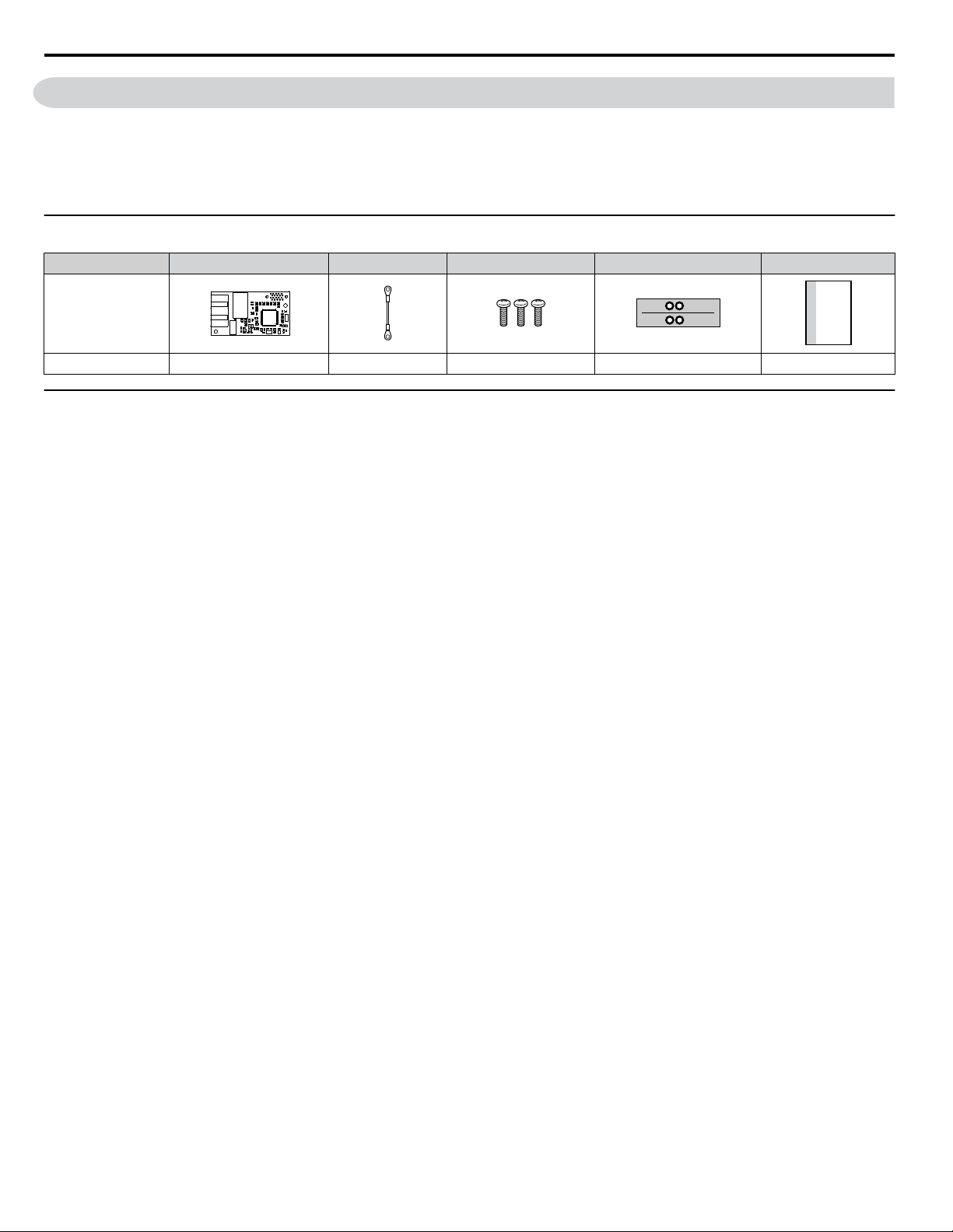
Option Package Contents
Description Option Ground Wire Screws (M3) LED Label Installation Manual
–
Quantity 1 1 3 1 1
u
Tools Required for Installation
• A Phillips screwdriver (M3 metric or #1, #2 U.S. standard) is required to install the option and remove drive front covers.
Screw sizes vary by drive capacity. Select a screwdriver appropriate for the drive capacity.
• Diagonal cutting pliers. (required for some drive models)
• A small file or medium grit sandpaper. (required for some drive models)
Note: Tools required to prepare the option cables for wiring are not listed in this manual.
8
YASKAWA SIEP YAICOM 16A 1000-Series Option Dual-Port EtherNet/IP SI-EN3D Technical Manual
Page 9
4 Option Components
M
A
I
H
G
E
B
D
F
C
J
K
L
Underside
Latch release
1 2 3 4 5 6 7 8
u
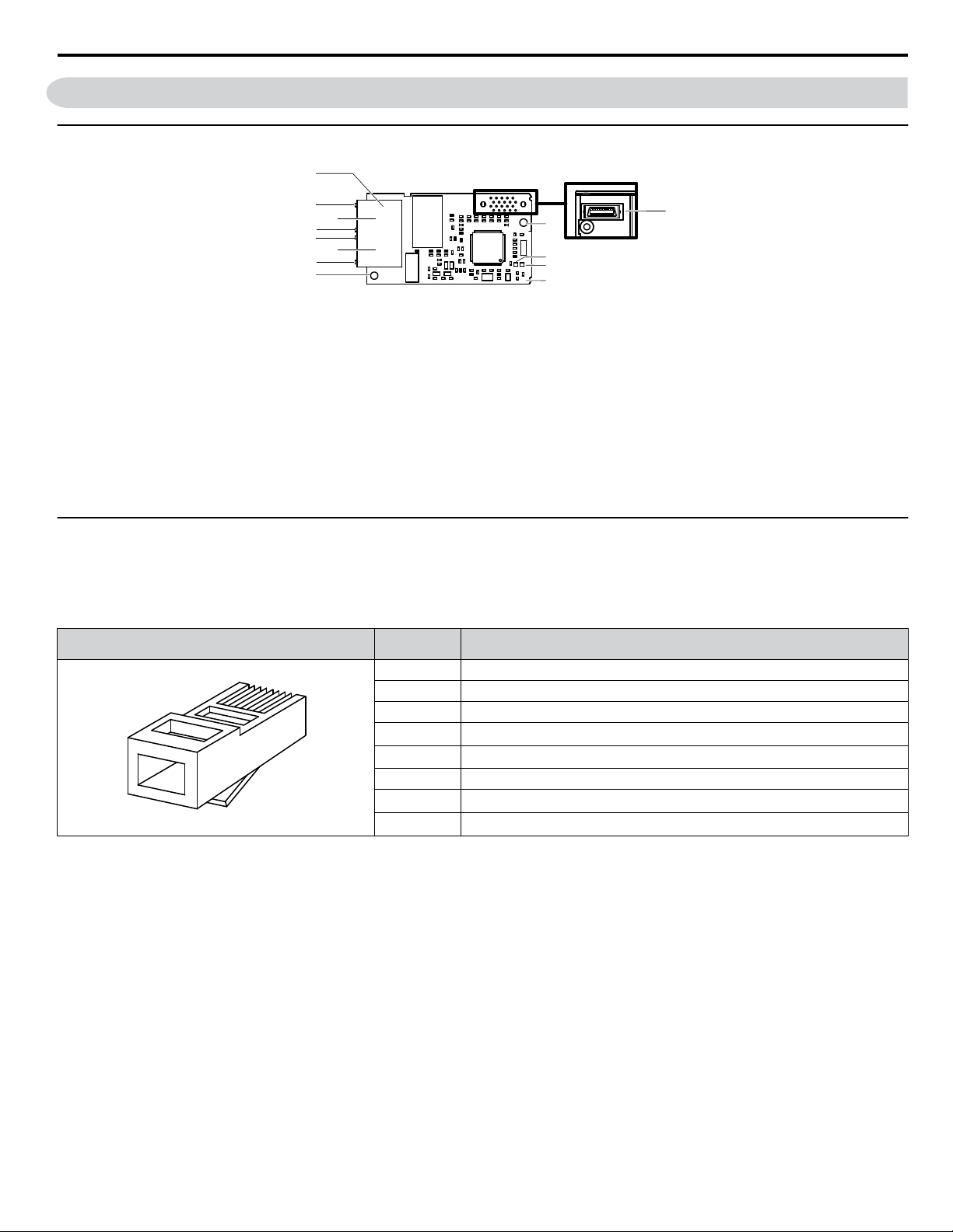
SI-EN3D Dual-Port EtherNet/IP Option
4 Option Components
A – Ground terminal and installation
<1>
hole
B –
Port 2 LED (10/100)
<2>
C – Port 2
D –
Port 2 LED (LINK/ACT)
E –
Port 1 LED (10/100)
<2>
<2>
H – EtherNet/IP cable connector
I – Option connector
J – Installation hole
K –
LED (MS)
L –
LED (NS)
<2>
<2>
M – EtherNet/IP PCB
F – Port 1
G –
Port 1 LED (LINK/ACT)
<2>
Figure 1 Option Components
<1> The ground wire is packaged loose in the option shipping package. Connect this ground wire during installation.
<2> Refer to Option LED Display on page 10 for details on the LEDs.
u
Communication Connector CN1
The communication connector on the option is a modular RJ45 female connector designated CN1.
CN1 is the connection point for a customer-supplied male Ethernet network communication cable.
Table 2 Male, 8-Way Ethernet Modular Connector (Customer-Supplied)
Male Ethernet 8-Way Modular Connector
<1> Not used for 10 Mbps and 100 Mbps networks.
Pin Description
1 (Pair 2) Transmit data (TXD) +
2 (Pair 2) Transmit data (TXD) -
3 (Pair 3) Receive data (RXD) +
4 (Pair 1)
5 (Pair 1)
Not used
Not used
<1>
<1>
6 (Pair 3) Receive data (RXD) -
7 (Pair 4)
8 (Pair 4)
Not used
Not used
<1>
<1>
YASKAWA SIEP YAICOM 16A 1000-Series Option Dual-Port EtherNet/IP SI-EN3D Technical Manual
9
Page 10

4 Option Components
u
Option LED Display
The option has four LEDs.
Bi-color Status LEDs:
• Module status (MS) red/green
• Network status (NS) red/green
Ethernet LEDs:
• Network speed - 10/100 (MS) green
• Link status and network activity - LINK/ACT (NS) red/green
The operational states of the option LEDs after completion of the power-up diagnostic LED sequence are described in Table
3. Wait at least 2 seconds for the power-up diagnostic process to complete before verifying LED states.
Table 3 Option LED States
Name
MS
NS
<1>
10/100
LINK/ACT
<1> Remove the cover to check the status of the LED. Be careful not to touch the main circuit terminals or the control board in the drive.
<1>
Color Status
Green ON Normal operation
Green Flashing Standby/Initializing
Red Flashing Non-fatal error occurred
Red ON Fatal error occurred The option has detected an unrecoverable major fault.
Green/Red Flashing Option self-test The option is in self-test mode.
Green ON
Green Flashing Not connected The option is online without an established connection.
Red Flashing Minor fault A minor recoverable fault has occurred.
Red ON Major fault The option detected a duplicate IP address.
Green/Red Flashing Option self-test The option is in self-test mode.
Green OFF 10 Mbps is established
Green ON 100 Mbps is established
Green OFF LINK is not established
Green ON LINK is established
Green Flashing
Display
– OFF Power supply OFF Power is not being supplied to the drive.
– OFF Power supply OFF –
Operating Status Remarks
The option is operating normally and initialization is
complete.
The option is in process of configuring or waiting for
configuration information.
The option has detected a recoverable minor fault such
as incomplete configuration.
Online communications
established
LINK is established and there is
network activity.
The option is online and has established connections.
–
Power-Up Diagnostics
n
An LED test is performed each time the drive is powered up. The initial boot sequence may take several seconds. After the
LEDs have completed the diagnostic LED sequence, the option is successfully initialized. The LEDs then assume operational
conditions as shown in Table 3.
Table 4 Power-Up Diagnostic LED Sequence
Sequence Module Status (MS) Network Status (NS) Time (ms)
1 Green OFF 250
2 Red OFF 250
3 Green OFF –
4 Green Green 250
5 Green Red 250
6 Green OFF –
10
YASKAWA SIEP YAICOM 16A 1000-Series Option Dual-Port EtherNet/IP SI-EN3D Technical Manual
Page 11
5 Installation Procedure
5 Installation Procedure
u
Section Safety
DANGER
Electrical Shock Hazard
Do not connect or disconnect wiring while the power is on.
Failure to comply will result in death or serious injury.
Disconnect all power to the drive and wait at least the amount of time specified on the drive front cover safety label. After
all indicators are off, measure the DC bus voltage to confirm safe level, and check for unsafe voltages before servicing. The
internal capacitor remains charged after the power supply is turned off.
WARNING
Electrical Shock Hazard
Do not remove the front covers of the drive while the power is on.
Failure to comply could result in death or serious injury.
The diagrams in this section may include options and drives without covers or safety shields to show details. Be sure to
reinstall covers or shields before operating any devices. The option should be used according to the instructions described
in this manual.
Do not allow unqualified personnel to use equipment.
Failure to comply could result in death or serious injury.
Maintenance, inspection, and replacement of parts must be performed only by authorized personnel familiar with installation,
adjustment, and maintenance of this product.
Do not touch circuit boards while the power is on.
Failure to comply could result in death or serious injury.
Do not use damaged wires, stress the wiring, or damage the wire insulation.
Failure to comply could result in death or serious injury.
Do not use damaged wires, place excessive stress on wiring, or damage the wire insulation.
Failure to comply could result in death or serious injury.
Fire Hazard
Tighten all terminal screws to the specified tightening torque.
Loose electrical connections could result in death or serious injury by fire due to overheating of electrical connections.
NOTICE
Observe proper electrostatic discharge procedures (ESD) when handling the drive and circuit boards.
Failure to comply may result in ESD damage to the drive circuitry.
Never shut the power off while the drive is outputting voltage.
Failure to comply may cause the application to operate incorrectly or damage the drive.
Do not operate damaged equipment.
Failure to comply may cause further damage to the equipment.
Do not connect or operate any equipment with visible damage or missing parts.
Do not use unshielded cable for control wiring.
Failure to comply may cause electrical interference resulting in poor system performance.
Use shielded twisted-pair wires and ground the shield to the ground terminal of the drive.
YASKAWA SIEP YAICOM 16A 1000-Series Option Dual-Port EtherNet/IP SI-EN3D Technical Manual
11
Page 12
I
J
K
M
A
L
D
F
G
C
E
B
H
NS MS
NS MS
5 Installation Procedure
NOTICE
Properly connect all pins and connectors.
Failure to comply may prevent proper operation and possibly damage equipment.
Check wiring to ensure that all connections are correct after installing the option and connecting any other devices.
Failure to comply could result in damage to the option.
u
Prior to Installing the Option
Prior to installing the option, wire the drive, make necessary connections to the drive terminals, and verify that the drive
functions normally without the option installed. Refer to the drive Quick Start Guide for information on wiring and connecting
the drive.
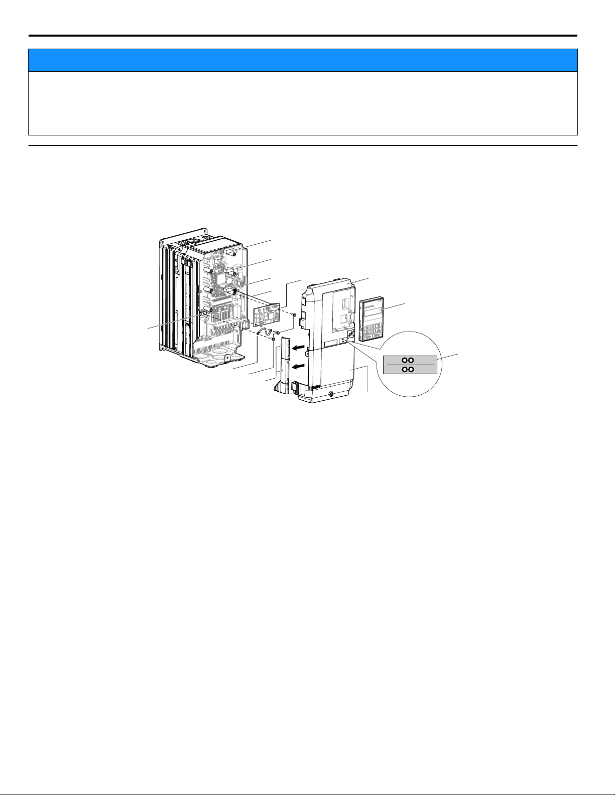
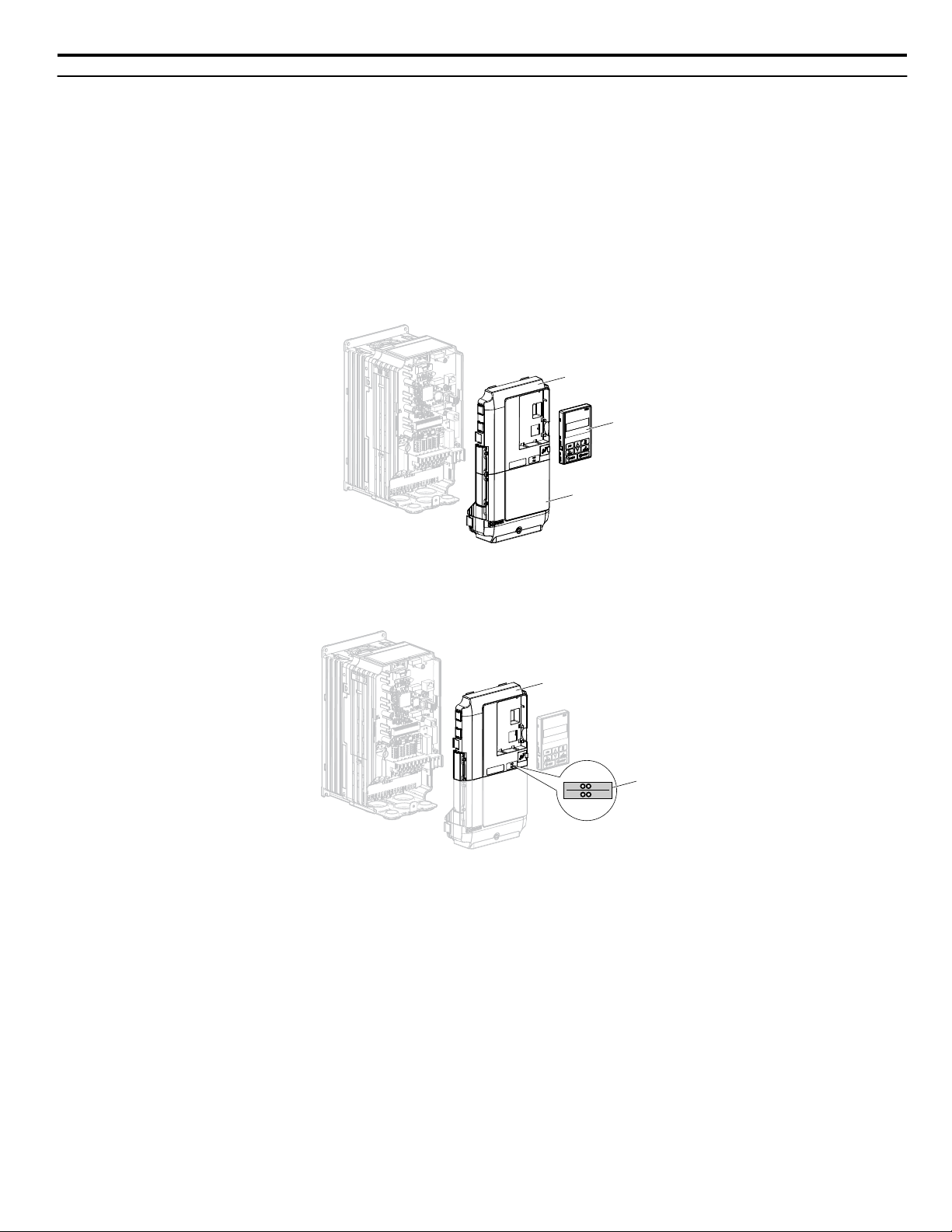
Figure 2 shows an exploded view of the drive with the option and related components for reference.
A – Drive front cover
B – Digital operator
C – LED label
D – Drive terminal cover
E – Removable tabs for wire routing
F – Included screws
G – Ground wire
Figure 2 Drive Components with Option
H – Drive grounding terminal (FE)
I – Connector CN5-C
J – Connector CN5-B
K – Connector CN5-A
L – Insertion point for CN5 connector
M – Option
12
YASKAWA SIEP YAICOM 16A 1000-Series Option Dual-Port EtherNet/IP SI-EN3D Technical Manual
Page 13
A
B
D
A
C
NS MS
5 Installation Procedure
u
Installing the Option
Remove the front covers of the drive before installing the option. Refer to the drive Quick Start Guide for directions on
removing the front covers. Cover removal varies depending on drive size. This option can only be inserted into the CN5-A
connector located on the drive control board.
DANGER! DANGER! Electrical Shock Hazard. Do not connect or disconnect wiring while the power is on. Failure to comply could result in
death or serious injury. Before installing the option, disconnect all power to the drive and wait at least the amount of time specified on the
drive front cover safety label. After all indicators are off, measure the DC bus voltage to confirm safe level, and check for unsafe voltages
before servicing. The internal capacitor remains charged after the power supply is turned off.
Shut off power to the drive, wait the appropriate amount of time for voltage to dissipate, then remove the digital operator
1.
(B) and front covers (A, D). Front cover removal varies by model.
NOTICE: Damage to Equipment. Observe proper electrostatic discharge procedures (ESD) when handling the option, drive, and
circuit boards. Failure to comply may result in ESD damage to circuitry.
Figure 3 Remove the Front Covers and Digital Operator
With the front covers and digital operator removed, apply the LED label (C) in the appropriate position on the drive
2.
top front cover (A).
Figure 4 Apply the LED Label
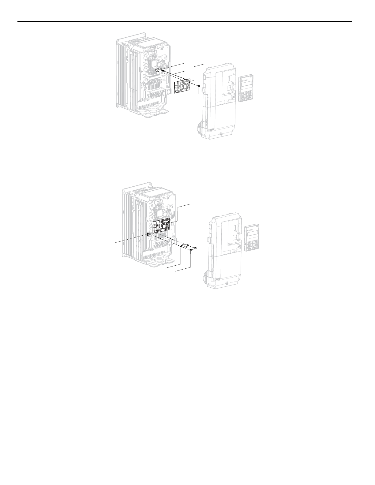
Make sure the screws on the left and right sides of the option terminal block (J) are tightened with a tightening torque
3.
of 0.5 to 0.6 Nm (4.4 to 5.3 in lbs), then insert the option (B) into the CN5-A connector (L) located on the drive and
fasten it using one of the included screws (H).
YASKAWA SIEP YAICOM 16A 1000-Series Option Dual-Port EtherNet/IP SI-EN3D Technical Manual
13
Page 14
NS MS
K
L
F
M
TX RX
NS MS
F
G
M
H
TX RX
5 Installation Procedure
Connect the ground wire (I) to the ground terminal (K) using one of the remaining provided screws (H). Connect the
4.
other end of the ground wire (I) to the remaining ground terminal and installation hole on the option (B) using the last
remaining provided screw (H) and tighten both screws to 0.5 to 0.6 N•m (4.4 to 5.3 in lbs).
Figure 5 Insert the Option
Figure 6 Connect the Ground Wire
Note:
There are two screw holes on the drive for use as ground terminals. When connecting three options, two ground wires will need
to share the same drive ground terminal.
Route the option wiring.
5.
Depending on the drive model, some drives may require routing the wiring through the side of the front cover to the
outside to provide adequate space for the wiring. Refer to the Peripheral Devices & Options section of the drive Quick
Start Guide or Technical Manual for more information on wire routing of specific models.
Route the wiring through the side of the front cover to the outside. In these cases, using diagonal cutting pliers, cut
out the perforated openings on the left side of the drive front cover as shown in Figure 7-A. Use a file or sandpaper
to make the sharp edges along the cutout smoother to prevent any damage to the wires. Route the wiring inside the
enclosure as shown in Figure 7-B for drives that do not require routing through the front cover.
Note: Separate communication cables from main circuit wiring and other electrical lines.
14
YASKAWA SIEP YAICOM 16A 1000-Series Option Dual-Port EtherNet/IP SI-EN3D Technical Manual
Page 15
A
B
Yaskawa
Drive
Yaskawa
Drive
Yaskawa
Drive
Yaskawa
Drive
Yaskawa
Drive
Yaskawa
Drive
Yaskawa
Drive
Yaskawa
Drive
Yaskawa
Drive
Star Topology
Daisy-Chained Topology
Ring Topology
5 Installation Procedure
A – Route wires through the openings
provided on the left side of the front
<1>
cover.
B – Use the open space provided
inside the drive to route option
wiring.
Figure 7 Wire Routing Examples
<1> The drive will not meet NEMA Type 1 requirements if wiring is exposed outside the enclosure.
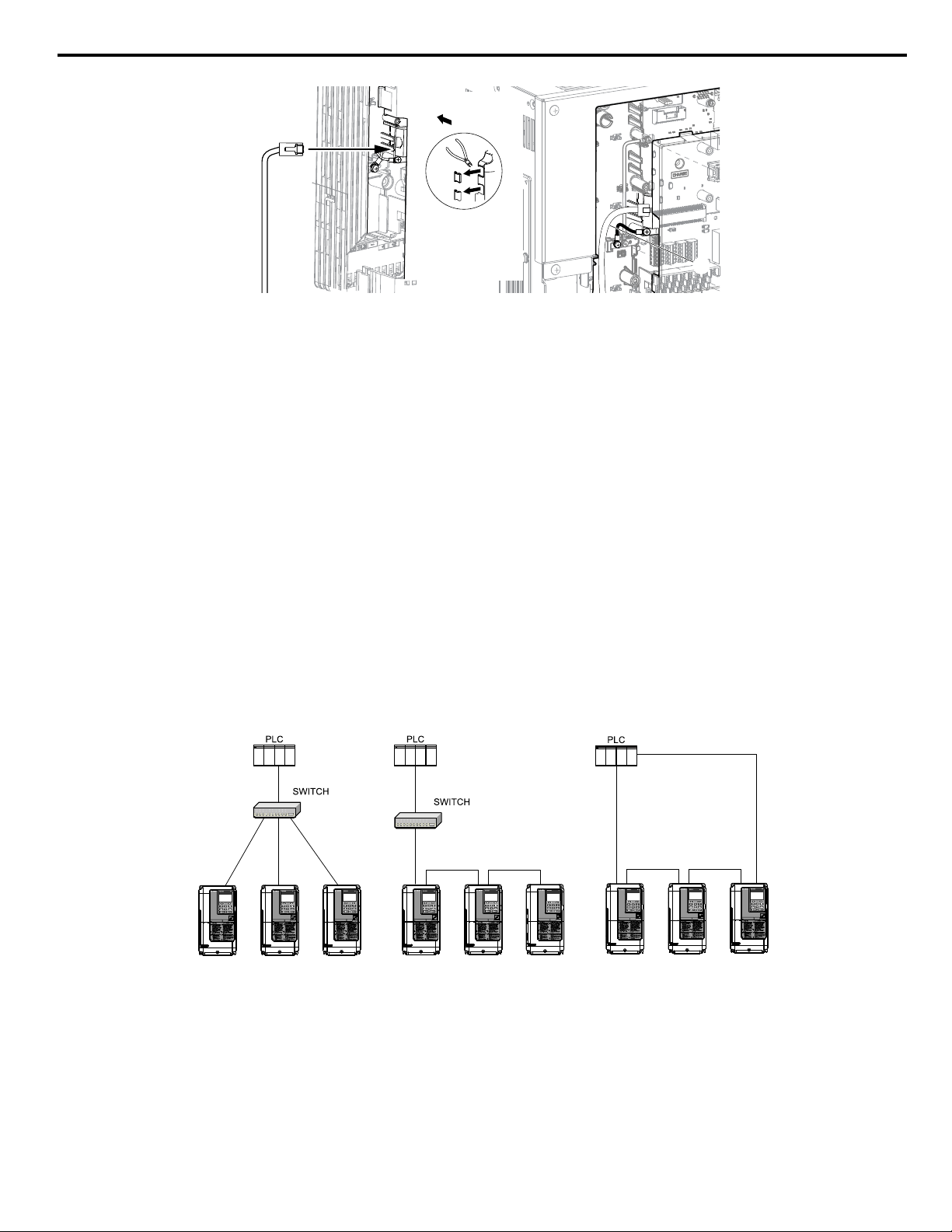
Connect the Ethernet communication cable to the option modular connector (CN1) port 1.
6.
To connect the option to a network, firmly connect RJ45 8-pin shielded twisted pair Cat5e cable(s) into the modular
connector ports (see Figure 7).
IGMP Snooping
Switches implementing IGMP Snooping are strongly recommended. When IGMP Snooping is used, devices will only
receive the multicast packets in which they are interested.
Communication Cable Specifications
Only use cable recommended for EtherNet/Industrial Protocol (EtherNet/IP™). Using a cable not specifically
recommended may cause the option or drive to malfunction. Refer to the ODVA website for more information on
network cabling (http://www.odva.org).
The dual RJ45 network ports on the option board act as a switch to allow for flexibility in cabling topology. For example,
a traditional star network topology may be employed by using a single port on the option board. Alternatively, a daisychained approach may be employed by using both RJ45 ports. The daisy-chained approach reduces the requirements
of central switch ports. A ring topology is also possible.
Figure 8 Topology Options
YASKAWA SIEP YAICOM 16A 1000-Series Option Dual-Port EtherNet/IP SI-EN3D Technical Manual
15
Page 16
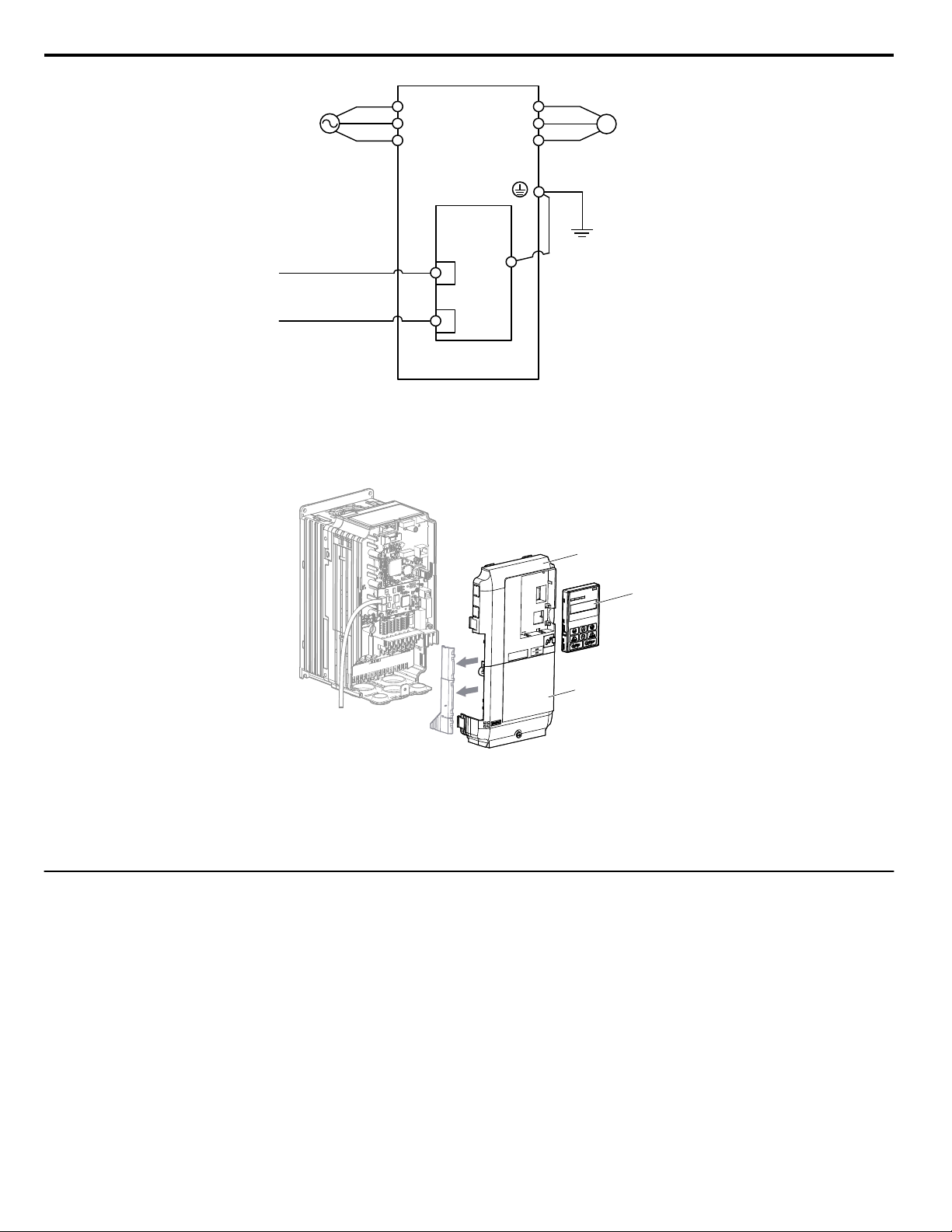
Drive
M
U/T1
V/T2
W/T3
R/L1
S/L2
T/L3
SI-EN3D
EtherNet/IP
Option
FE
<1>
EtherNet/IP Cable
MotorPower
EtherNet/IP Cable
D
A
B
NS MS
TX RX
5 Installation Procedure
Use the second communication cable port to daisy chain a series of drives where applicable.
7.
Replace and secure the front covers of the drive (A, D) and replace the digital operator (B).
8.
Figure 9 Option Connection Diagram
Figure 10 Replace the Front Covers and Digital Operator
Note: Take proper precautions when wiring the option so that the front covers will easily fit back onto the drive. Make sure no cables
9.
u
EDS Files
are pinched between the front covers and the drive when replacing the covers.
Set drive parameters in Table 5 for proper option performance.
For easy network implementation of drives equipped with the option, an EDS file can be obtained from:
U.S.: http://www.yaskawa.com
Europe: http://www.yaskawa.eu.com
Japan: http://www.e-mechatronics.com
Other areas: Contact a Yaskawa representative.
Note: Download the option EDS file. The option will not function as a slave in the network without the appropriate EDS file.
16
YASKAWA SIEP YAICOM 16A 1000-Series Option Dual-Port EtherNet/IP SI-EN3D Technical Manual
Page 17

6 Related Drive Parameters
6 Related Drive Parameters
The following parameters are used to set up the drive for operation with the option. Parameter setting instructions can be found
in the drive manual.
Confirm proper setting of the parameters in Table 5 before starting network communications. After changing parameter
settings, cycle power to the drive for the new settings to take effect.
Table 5 Related Parameters
No.
(Addr.
Hex)
b1-01
(0180)
<1>
b1-02
(0181)
<1>
F6-01
(03A2)
F6-02
(03A3)
F6-03
(03A4)
F6-06
(03A7)
<3>
F6-07
(03A8)
F6-08
(036A)
<5>
F6-14
(03BB)
F7-01
(03E5)
<6>
F7-02
(03E6)
<6>
F7-03
(03E7)
<6>
F7-04
(03E8)
<6>
F7-05
(03E9)
F7-06
(03EA)
F7-07
(03EB)
F7-08
(03EC)
Frequency Reference Selection
1
Run Command
Selection 1
Communications Error
Operation Selection
External Fault from Comm.
Option Detection Selection
External Fault from Comm.
Option Operation Selection
Torque Reference/Torque
Limit Selection from Comm.
Option
Multi-Step Speed Enable/
Disable Selection when
NefRef/ComRef is Selected
Reset Communication
Parameters
bUS Error Auto Reset
IP Address 1 Sets the most significant octet of network static IP address.
IP Address 2 Sets the second most significant octet of network static IP address.
IP Address 3 Sets the third most significant octet of network static IP address.
IP Address 4 Sets the fourth most significant octet of network static IP address.
Subnet Mask 1 Sets the most significant octet of network static Subnet Mask.
Subnet Mask 2 Sets the second most significant octet of network static Subnet Mask.
Subnet Mask 3 Sets the third most significant octet of network static Subnet Mask.
Subnet Mask 4 Sets the fourth most significant octet of network static Subnet Mask.
Name Description Values
0: Digital operator
1: Analog input terminals
2: MEMOBUS/Modbus communications
3: Option PCB
Default: 1
Range: 0 to 4
4: Pulse input (terminal RP)
0: Digital operator
1: Digital input terminals
2: MEMOBUS/Modbus communications
Default: 1
Range: 0 to 3
3: Option PCB
0: Ramp to stop. Decelerate to stop using the deceleration time in C1-02.
1: Coast to stop
2: Fast Stop. Decelerate to stop using the deceleration time in C1-09.
3: Alarm only
<2>
1: Detection during run only
Default: 1
Range: 0 to 3
Default: 0
Range: 0, 1
0: Ramp to stop. Decelerate to stop using the deceleration time in C1-02.
1: Coast to stop
2: Fast Stop. Decelerate to stop using the deceleration time in C1-09.
3: Alarm only
0: Disabled. Torque reference/limit from option board disabled.
1: Enabled. Torque reference/limit from option board enabled.
<2>
<4>
0: Multi-step reference disabled (same as F7)
1: Multi-step reference enabled (same as V7)
Default: 1
Range: 0 to 3
Default: 0
Range: 0, 1
Default: 0
Range: 0, 1
0: Communication-related parameters (F6-oo/F7-oo) are not reset when
the drive is initialized using A1-03.
1: Reset all communication-related parameters
Default: 0
Range: 0, 1
(F6-oo/F7-oo) when the drive is initialized using A1-03.
0: Disabled
1: Enabled
Default: 0
Range: 0, 1
Default: 192
Range: 0 to 255
Default: 168
Range: 0 to 255
Default: 1
Range: 0 to 255
Default: 20
Range: 0 to 255
Default: 255
Range: 0 to 255
Default: 255
Range: 0 to 255
Default: 255
Range: 0 to 255
Default: 0
Range: 0 to 255
YASKAWA SIEP YAICOM 16A 1000-Series Option Dual-Port EtherNet/IP SI-EN3D Technical Manual
17
Page 18

6 Related Drive Parameters
No.
(Addr.
Hex)
F7-09
(03ED)
F7-10
(03EE)
F7-11
(03EF)
F7-12
(03E0)
F7-13
(03F1)
F7-14
(03F2)
F7-15
(03F3)
F7-16
(03F4)
F7-17
(03F5)
F7-18
(03F6)
F7-19
(03F7)
F7-20
(03F8)
F7-21
(03F9)
F7-22
(03FA)
Gateway Address 1 Sets the most significant octet of network Gateway address.
Gateway Address 2 Sets the second most significant octet of network Gateway address.
Gateway Address 3 Sets the third most significant octet of network Gateway address.
Gateway Address 4 Sets the fourth most significant octet of network Gateway address.
Address Mode at Startup
Duplex Mode Selection
Communication Speed
Selection
Communication Loss Timeout
EtherNet/IP Speed Scaling
Factor
EtherNet/IP Current Scaling
Factor
EtherNet/IP Torque Scaling
Factor
EtherNet/IP Power Scaling
Factor
EtherNet/IP Voltage Scaling
Factor
EtherNet/IP Time Scaling
F7-23 to
F7-32
(03FB to
Dynamic Output Assembly
Parameters
0374)
F7-33 to
F7-42
(0375 to
Dynamic Input Assembly
Parameters
037E)
<1> To start and stop the drive with the EtherNet/IP master device using serial communications, set b1-02 to 3 or set the “Net Control” bit in the
assemblies or Control Supervisor Object. To control the drive frequency reference of the drive via the master device, set b1-01 to 3 or set the Net
Reference bit in the assemblies or AC/DC Object.
<2> When set to 3, the drive will continue to operate when a fault is detected. Take safety measures, such as installing an emergency stop switch.
Name Description Values
Default: 192
Range: 0 to 255
Default: 168
Range: 0 to 255
Default: 1
Range: 0 to 255
Default: 1
Range: 0 to 255
Select the option address setting method
<7>
0: Static
1: BOOTP
Default: 2
Range: 0 to 2
2: DHCP
Selects duplex mode setting.
0: Half duplex forced
1: Auto-negotiate duplex mode and communication speed
2: Full duplex forced
3: Half (port 1)/Auto (port 2)
4: Half (Port 1)/Full (port 2)
<8>
<8>
Default: 1
Range: 0 to 8
<9>
5: Auto (port 1)/Half (port 2)
6: Auto (port 1)/Full (port 2)
7: Full (port 1)/Half (port 2)
8: Full (port 1)/Auto (port 2)
Sets the communication speed
10: 10 Mbps
100: 100 Mbps
101: 10 (Port 1)/100 Mbps (port 2)
Default: 10
Range: 10; 100 to 102
102: 100 (Port 1)/10 Mbps (port 2)
Sets the timeout value for communication loss detection in tenths of a second.
A value of 0 disables the connection timeout.
Example: An entered value of 100 represents 10.0 seconds.
Sets the scaling factor for the speed monitor in EtherNet/IP Class ID 2AH
Object.
Sets the scaling factor for the output current monitor in EtherNet/IP Class ID
2AH Object.
Sets the scaling factor for the torque monitor in EtherNet/IP Class ID 2AH
Object.
Sets the scaling factor for the power monitor in EtherNet/IP Class ID 2AH
Object.
Sets the scaling factor for the voltage monitor in EtherNet/IP Class ID 2AH
Object.
Sets the scaling factor for the time monitor in EtherNet/IP Class ID 2AH
Object.
Default: 0.0
Min.: 0.0
Max.: 30.0
Default: 0
Min.: -15
Max.: 15
Default: 0
Min.: -15
Max.: 15
Default: 0
Min.: -15
Max.: 15
Default: 0
Min.: -15
Max.: 15
Default: 0
Min.: -15
Max.: 15
Default: 0
Min.: -15
Max.: 15
Parameters used in Output Assembly 116. Each parameter contains a
MEMOBUS/Modbus address. The value received for Output Assembly 116
will be written to this corresponding MEMOBUS/Modbus address. A
MEMOBUS/Modbus address value of 0 means that the value received for
Default: 0
Output Assembly 116 will not be written to any MEMOBUS/Modbus
register.
Parameters used in Input Assembly 166. Each parameter contains a
MEMOBUS/Modbus address. The value sent for Input Assembly 166 will
be read from this corresponding MEMOBUS/Modbus address. A
MEMOBUS/Modbus address value of 0 means that the value sent for Input
Default: 0
Assembly 166 is not defined by the user, therefore the option default register
value will be returned.
<10>
18
YASKAWA SIEP YAICOM 16A 1000-Series Option Dual-Port EtherNet/IP SI-EN3D Technical Manual
Page 19

6 Related Drive Parameters
<3> Enabled in CLV, AOLV/PM, and CLV/PM control modes (A1-02 = 3, 6, or 7). When enabled, d5-01 determines whether the value is read as the
Torque Limit value (d5-01 = 0) or read as the Torque Reference value (d5-01 = 1). In CLV/PM, this value is read as the Torque Limit.
<4> The setting specifies that the Torque Reference or Torque Limit is to be provided via network communications (F6-06 = 1). The motor may rotate
if no torque reference or Torque Limit is supplied from the PLC.
<5> Parameter setting value is not reset to the default value when the drive is initialized.
<6> Cycle power for setting changes to take effect.
<7> When F7-13 is set to 0, parameters F7-01 to F7-12 must be set, and all IP Addresses (as defined with parameters F7-01 to F7-04) must be unique.
<8> When F7-14 is set to 0 or 2, parameter F7-15 must be set.
<9> Setting range differs depending on drive software version. PRG: 1020 and earlier, Range: 0 to 2
PRG: 1021 and later, Range: 0 to 8
<10> Setting range differs depending on drive software version. PRG: 1020 and earlier, Range: 10, 100
PRG: 1021 and later, Range: 10; 100 to 102
Table 6 Option Monitors
No. Name Description Value Range
U6-80 to
U6-83
U6-84 to
U6-87
U6-88 to
U6-91
U6-92 Online Speed Link Speed
U6-93 Online Duplex Duplex Setting 0: Half, 1: Full
U6-94 Port 2 Duplex Port 2 Duplex Setting 0: Half, 1: Full
U6-95 Port 2 Speed Port 2 Link Speed
U6-98 First Fault First Option Fault –
U6-99 Current Fault Current Option Fault –
Online IP Address IP Address currently available; U6-80 is the most significant octet 0 to 255
Online Subnet Subnet currently available; U6-84 is the most significant octet 0 to 255
Online Gateway Gateway currently available; U6-88 is the most significant octet 0 to 255
10: 10 Mbps
100: 100 Mbps
10: 10 Mbps
100: 100 Mbps
YASKAWA SIEP YAICOM 16A 1000-Series Option Dual-Port EtherNet/IP SI-EN3D Technical Manual
19
Page 20

7 Configuring Messaging
7 Configuring Messaging
This section provides information on methods used to control the drive with the option installed.
u
Drive Polled Configuration
The assemblies in Table 7 are available for polled I/O:
Table 7 Supported Polled I/O Assemblies
Assembly
Number (Hex)
20 (14) Basic Speed Control Output Output 4 21
21 (15) Extended Speed Control Output Output 4 21
22 (16) Speed and Torque Control Output Output 6 22
23 (17) Extended Speed and Torque Control Output Output 6 22
70 (46) Basic Speed Control Input Input 4 29
71 (47) Extended Speed Control Input Input 4 29
72 (48) Speed and Torque Control Input Input 6 30
73 (49) Extended Speed and Torque Control Input Input 6 30
100 (64)
101 (65) (Vendor Specific Yaskawa Electric (YE) Assy)-Speed/Torque Control Output Output 8 23
115 (73)
116 (74) (Vendor Specific Yaskawa Electric (YE) Assy)-High Speed/Torque Control Output Output 44 26
150 (96)
151 (97) (Vendor Specific Yaskawa Electric (YE) Assy)-Speed/Torque Status Input Input 8 32
155 (9B)
166 (A6) (Vendor Specific Yaskawa Electric (YE) Assy)-High Speed/Torque Status Input Input 44 36
(Vendor Specific Yaskawa Electric (YE) Assy)-MEMOBUS/Modbus Message
Output
(Vendor Specific Yaskawa Electric (YE) Assy)-Extended Speed/Torque Control
Output
(Vendor Specific Yaskawa Electric (YE) Assy)-MEMOBUS/Modbus Message
Input
(Vendor Specific Yaskawa Electric (YE) Assy)- Extended Speed/ Torque Status
Input
Description Type Bytes Page
Output 5 23
Output 40 25
Input 5 31
Input 40 33
20
YASKAWA SIEP YAICOM 16A 1000-Series Option Dual-Port EtherNet/IP SI-EN3D Technical Manual
Page 21
8 Output Assemblies (Drive Consumes)
8 Output Assemblies (Drive Consumes)
Note: The convention in this manual is from the PLC perspective. As such, an assembly is called an “Output Assembly” when outputted from the
u
Basic Speed Control Output - 20 (0x14)
Output Instance Word Byte Bit 7 Bit 6 Bit 5 Bit 4 Bit 3 Bit 2 Bit 1 Bit 0
PLC and received by this node. This section details “Output Assemblies” that are “Consumed” by this drive.
0
20
1
Name Description
Run Fwd
Fault Reset
Speed Reference
Forward Run Command
0: Stop
1: Forward Run
Fault Reset
(0 to 1 transition: Fault Reset)
Speed Command
Sets drive speed reference.
Speed reference data: Frequency reference/2SS (SS: Speed scale)
Setting range: 0 to 0xFFFF
Example: setting a reference of 4096 with a speed scale of 2:
Speed reference data = 4096/22 = 1024 = 0x0400 Hex or 10.24 Hz
Unit depends on o1-03.
0 – – – – – Fault Reset – Run Fwd
1 –
2 Speed Reference (Low Byte)
3 Speed Reference (High Byte)
u
Extended Speed Control Output - 21 (0x15)
Output Instance Word Byte Bit 7 Bit 6 Bit 5 Bit 4 Bit 3 Bit 2 Bit 1 Bit 0
0
21
1
Name Description
Run Fwd
Run Rev
Fault Reset
NetCtrl
NetRef
Speed Reference
Forward Run Command
0: Stop
1: Forward Run
Reverse Run Command
0: Stop
1: Reverse Run
Fault Reset
(0 to 1 transition: Fault Reset)
Run command from Network
0: Depends on b1-02
1: Enables the run command from network
Speed reference from Network
0: Depends on b1-01
1: Enables the speed reference from network
Speed Command
Sets drive speed reference.
Speed reference data: Frequency reference/2SS (SS: Speed scale)
Setting range: 0 to 0xFFFF
Example: setting a reference of 4096 with a speed scale of 2:
Speed reference data = 4096/22 = 1024 = 0x0400 Hex
Unit depends on o1-03.
0 – NetRef NetCtrl – – Fault Reset Run Rev Run Fwd
1 –
2 Speed Reference (Low Byte)
3 Speed Reference (High Byte)
YASKAWA SIEP YAICOM 16A 1000-Series Option Dual-Port EtherNet/IP SI-EN3D Technical Manual
21
Page 22

8 Output Assemblies (Drive Consumes)
u
Speed and Torque Control Output - 22 (0x16)
Output Instance Word Byte Bit 7 Bit 6 Bit 5 Bit 4 Bit 3 Bit 2 Bit 1 Bit 0
0 – – – – – Fault Reset – Run Fwd
1 –
2 Speed Reference (Low Byte)
3 Speed Reference (High Byte)
4 Torque Reference/Torque Limit (Low Byte)
5 Torque Reference/Torque Limit (High Byte)
22
Name Description
Run Fwd
Fault Reset
Speed Reference
Torque Reference/Torque
Limit
0
1
2
Forward Run Command
0: Stop
1: Forward Run
Fault Reset
(0 to 1 transition: Fault Reset)
Speed Command
Sets drive speed reference.
Speed reference data: Frequency reference/2SS (SS: Speed scale)
Setting range: 0 to 0xFFFF
Example: setting a reference of 4096 with a speed scale of 2:
Speed reference data = 4096/22 = 1024 = 0x0400 Hex
Unit depends on o1-03.
Torque Reference/Torque Limit
Sets the Torque Reference/Torque Limit in units of 0.1%.
Sets the Torque Reference when using Torque Control (d5-01 = 1).
Sets the Torque Limit when using Speed Control (d5-01 = 0).
The Torque Reference and Torque Limit are disabled with F6-06 = 0.
u
Extended Speed and Torque Control Output - 23 (0x17)
Output Instance Word Byte Bit 7 Bit 6 Bit 5 Bit 4 Bit 3 Bit 2 Bit 1 Bit 0
0
23
Name Description
Run Fwd
Run Rev
Fault Reset
NetCtrl
NetRef
Speed Reference
1
2
Forward Run Command
0: Stop
1: Forward Run
Reverse Run Command
0: Stop
1: Reverse Run
Fault Reset
(0 to 1 transition: Fault Reset)
Run command from Network
0: Depends on b1-02
1: Enables the run command from network
Speed reference from Network
0: Depends on b1-01
1: Enables the speed reference from network
Speed Command
Sets drive speed reference.
Speed reference data: Frequency reference/2SS (SS: Speed scale)
Setting range: 0 to 0xFFFF
Example: setting a reference of 4096 with a speed scale of 2:
Speed reference data = 4096/22 = 1024 = 0x0400 Hex
Unit depends on o1-03.
0 – NetRef NetCtrl – – Fault Reset Run Rev Run Fwd
1 –
2 Speed Reference (Low Byte)
3 Speed Reference (High Byte)
4 Torque Reference/Torque Limit (Low Byte)
5 Torque Reference/Torque Limit (High Byte)
22
YASKAWA SIEP YAICOM 16A 1000-Series Option Dual-Port EtherNet/IP SI-EN3D Technical Manual
Page 23

8 Output Assemblies (Drive Consumes)
Name Description
Torque Reference/Torque Limit
Torque Reference/Torque
u
Limit
MEMOBUS/Modbus Message Output (Vendor Specific Yaskawa Electric (YE) Assy) -
Sets the Torque Reference/Torque Limit in units of 0.1%.
Sets the Torque Reference when using Torque Control (d5-01 = 1).
Sets the Torque Limit when using Speed Control (d5-01 = 0).
The Torque Reference and Torque Limit are disabled with F6-06 = 0.
100 (0x64)
Output Instance Word Byte Bit 7 Bit 6 Bit 5 Bit 4 Bit 3 Bit 2 Bit 1 Bit 0
0
100
Note: This is a paired assembly (100/150).
Name Description
Function Code MEMOBUS/Modbus Function Code
Register Number MEMOBUS/Modbus Register Number
Register Data MEMOBUS/Modbus Register Data
1
2 4 Register Data (Low Byte)
0 Function Code
1 Register Number (High Byte)
2 Register Number (Low Byte)
3 Register Data (High Byte)
Table 8 Function Code Decode Table
Function Code MEMOBUS/Modbus Function
0x00 No Operation
0x03 Read Register
0x10 Write Register
Note: Refer to the MEMOBUS/Modbus Data Table in the MEMOBUS/Modbus Communications chapter of the drive manual for a list of monitor
u
Speed/Torque Control Output (Vendor Specific Yaskawa Electric (YE) Assy) - 101 (0x65)
Output Instance Word Byte Bit 7 Bit 6 Bit 5 Bit 4 Bit 3 Bit 2 Bit 1 Bit 0
data using the MEMOBUS/Modbus message area.
Multi-
Function
Input 8
Multi-
Function
Photo-
coupler 2
101
0
0
1
1
2
3
2 Speed Reference (Low Byte)
3 Speed Reference (High Byte)
4 Torque Reference/Torque Limit (Low Byte)
5 Torque Reference/Torque Limit (High Byte)
6 Torque Compensation (Low Byte)
7 Torque Compensation (High Byte)
Multi-
Function
Input 7
Multi-
Function
Photo-
coupler 1
Multi-
Function
Input 6
Multi-
Function
Digital
Output
Multi-
Function
Input 5
– – – Fault Reset
Multi-
Function
Input 4
Multi-
Function
Input 3
Run Rev Run Fwd
External
Fault
Name Description
Run Fwd
Run Rev
Multi-Function Input 3
YASKAWA SIEP YAICOM 16A 1000-Series Option Dual-Port EtherNet/IP SI-EN3D Technical Manual
Forward Run Command
0: Stop
1: Forward Run
Reverse Run Command
0: Stop
1: Reverse Run
Terminal S3 Function Input
0: Terminal S3 Function (H1-03) OFF
1: Terminal S3 Function (H1-03) ON
23
Page 24

8 Output Assemblies (Drive Consumes)
Name Description
Multi-Function Input 4
Multi-Function Input 5
Multi-Function Input 6
Multi-Function Input 7
Multi-Function Input 8
External Fault
Fault Reset
Multi-Function Digital
Output
Multi-Function
Photocoupler 1
Multi-Function
Photocoupler 2
Speed Reference
Torque Reference/Torque
Limit
Torque Compensation Sets the amount of Torque Compensation Sets in units of 0.1%.
Terminal S4 Function Input
0: Terminal S4 Function (H1-04) OFF
1: Terminal S4 Function (H1-04) ON
Terminal S5 Function Input
0: Terminal S5 Function (H1-05) OFF
1: Terminal S5 Function (H1-05) ON
Terminal S6 Function Input
0: Terminal S6 Function (H1-06) OFF
1: Terminal S6 Function (H1-06) ON
Terminal S7 Function Input
0: Terminal S7 Function (H1-07) OFF
1: Terminal S7 Function (H1-07) ON
Terminal S8 Function Input
0: Terminal S8 Function (H1-08) OFF
1: Terminal S8 Function (H1-08) ON
External Fault EF0
0: No External Fault (EF0)
1: External Fault (EF0)
Fault Reset
0: No Fault Reset
1: Fault Reset
Terminal M1/M2
0: M1/M2 OFF
1: M1/M2 ON
This function is enabled only when H2-01 is set to F.
Terminal P1
0: P1 OFF
1: P1 ON
This function is enabled only when H2-02 is set to F.
Terminal P2
0: P2 OFF
1: P2 ON
This function is enabled only when H2-03 is set to F.
Speed Command
Sets drive speed reference.
Unit depends on o1-03.
Unit is not affected by Speed Scale SS.
Torque Reference/Torque Limit
Sets the Torque Reference/Torque Limit in units of 0.1%.
Sets the Torque Reference when using Torque Control (d5-01 = 1).
Sets the Torque Limit when using Speed Control (d5-01 = 0).
The Torque Reference and Torque Limit are disabled with F6-06 = 0.
24
YASKAWA SIEP YAICOM 16A 1000-Series Option Dual-Port EtherNet/IP SI-EN3D Technical Manual
Page 25

8 Output Assemblies (Drive Consumes)
u
Extended Speed/Torque Control Output (Vendor Specific Yaskawa Electric (YE) Assy)
- 115 (0x73)
Output Instance Word Byte Bit 7 Bit 6 Bit 5 Bit 4 Bit 3 Bit 2 Bit 1 Bit 0
115
0
0
1
1
2
3
4/5 8-11 Reserved
6
7
8
9-20 18-39 Reserved
2 Speed Reference (Low Byte)
3 Speed Reference (High Byte)
4 Torque Reference/Torque Limit (Low Byte)
5 Torque Reference/Torque Limit (High Byte)
6 Torque Compensation (Low Byte)
7 Torque Compensation (High Byte)
12 Analog Output 1 (Low Byte)
13 Analog Output 1 (High Byte)
14 Analog Output 2 (Low Byte)
15 Analog Output 2 (High Byte)
16 Digital Outputs (Low Byte)
17 Digital Outputs (High Byte)
Multi-
Function
Input 8
Multi-
Function
Photo-
coupler 2
Multi-
Function
Input 7
Multi-
Function
Photo-
coupler 1
Multi-
Function
Input 6
Multi-
Function
Digital
Output
Multi-
Function
Input 5
– – – Fault Reset
Multi-
Function
Input 4
Multi-
Function
Input 3
Run Rev Run Fwd
External
Fault
Name Description
Run Fwd
Run Rev
Multi-Function Input 3
Multi-Function Input 4
Multi-Function Input 5
Multi-Function Input 6
Multi-Function Input 7
Multi-Function Input 8
External Fault
Fault Reset
Multi-Function Digital
Output
Forward Run Command
0: Stop
1: Forward Run
Reverse Run Command
0: Stop
1: Reverse Run
Terminal S3 Function Input
0: Terminal S3 Function (H1-03) OFF
1: Terminal S3 Function (H1-03) ON
Terminal S4 Function Input
0: Terminal S4 Function (H1-04) OFF
1: Terminal S4 Function (H1-04) ON
Terminal S5 Function Input
0: Terminal S5 Function (H1-05) OFF
1: Terminal S5 Function (H1-05) ON
Terminal S6 Function Input
0: Terminal S6 Function (H1-06) OFF
1: Terminal S6 Function (H1-06) ON
Terminal S7 Function Input
0: Terminal S7 Function (H1-07) OFF
1: Terminal S7 Function (H1-07) ON
Terminal S8 Function Input
0: Terminal S8 Function (H1-08) OFF
1: Terminal S8 Function (H1-08) ON
External Fault EF0
0: No External Fault (EF0)
1: External Fault (EF0)
Fault Reset
0: No Fault Reset
1: Fault Reset
Terminal M1/M2
0: M1/M2 OFF
1: M1/M2 ON
This function is enabled only when H2-01 is set to F.
YASKAWA SIEP YAICOM 16A 1000-Series Option Dual-Port EtherNet/IP SI-EN3D Technical Manual
25
Page 26

8 Output Assemblies (Drive Consumes)
Name Description
Multi-Function
Photocoupler 1
Multi-Function
Photocoupler 2
Speed Reference
Torque Reference/Torque
Torque Compensation Sets the amount of Torque Compensation Sets in units of 0.1%.
u
Limit
Analog Output 1 MEMOBUS/Modbus (0x0007)
Analog Output 2 MEMOBUS/Modbus (0x0008)
Digital Outputs MEMOBUS/Modbus (0x0009)
High Speed/Torque Control Output (Vendor Specific Yaskawa Electric (YE) Assy) - 116
Terminal P1
0: P1 OFF
1: P1 ON
This function is enabled only when H2-02 is set to F.
Terminal P2
0: P2 OFF
1: P2 ON
This function is enabled only when H2-03 is set to F.
Speed Command
Sets drive speed reference.
Unit depends on o1-03.
Unit is not affected by Speed Scale SS.
Torque Reference/Torque Limit
Sets the Torque Reference/Torque Limit in units of 0.1%.
Sets the Torque Reference when using Torque Control (d5-01 = 1).
Sets the Torque Limit when using Speed Control (d5-01 = 0).
The Torque Reference and Torque Limit are disabled with F6-06 = 0.
(0x74)
This assembly is dynamic and can be configured as to what parameters are used. The first 20 Bytes (0-19) are fixed and the
next 20 Bytes can be configured using parameters F7-23 to F7-32. If an error occurs while trying to write to the dynamic
parameters, the appropriate error bit in Assembly 166 will be set. If more information is needed as to the nature of the error,
the extended error status can be read explicitly through Class 4, Instance 0xA6, Attribute 0x64. This will return 20 Bytes with
each dynamic parameter in Assembly 116 having a Byte dedicated to its extended error status. Refer to Input Assemblies
(Drive Produces) on page 29 for more information.
Output Instance Word Byte Bit 7 Bit 6 Bit 5 Bit 4 Bit 3 Bit 2 Bit 1 Bit 0
116
0
0
1
1
2
3
4
5
6
2 Speed Reference (Low Byte)
3 Speed Reference (High Byte)
4 Torque Reference/Torque Limit (Low Byte)
5 Torque Reference/Torque Limit (High Byte)
6 Torque Compensation (Low Byte)
7 Torque Compensation (High Byte)
8 Reserved
9 – – – –
10 – – – – – – NetCtrl NetRef
11 – – – – – – – –
12 Analog Output 1 (Low Byte)
13 Analog Output 1 (High Byte)
Multi-
Function
Input 8
Multi-
Function
Photo-
coupler 2
Multi-
Function
Input 7
Multi-
Function
Photo-
coupler 1
Multi-
Function
Input 6
Multi-
Function
Digital
Output
Multi-
Function
Input 5
– – – Fault Reset
Multi-
Function
Input 4
Multi-
Function
Input 12
Multi-
Function
Input 3
MultiFunction
Input 11
Run Rev Run Fwd
Function
Input 10
Multi-
External
Fault
Multi-
Function
Input 9
26
YASKAWA SIEP YAICOM 16A 1000-Series Option Dual-Port EtherNet/IP SI-EN3D Technical Manual
Page 27

8 Output Assemblies (Drive Consumes)
Output Instance Word Byte Bit 7 Bit 6 Bit 5 Bit 4 Bit 3 Bit 2 Bit 1 Bit 0
14 Analog Output 2 (Low Byte)
15 Analog Output 2 (High Byte)
16 Digital Outputs (Low Byte)
17 Digital Outputs (High Byte)
18 Reserved
19 Reserved
Programmable Bytes
Defined by F7-23
Default: Not Used
Programmable Bytes
Defined by F7-24
Default: Not Used
Programmable Bytes
Defined by F7-25
Default: Not Used
Programmable Bytes
Defined by F7-26
Default: Not Used
Programmable Bytes
Defined by F7-27
Default: Not Used
Programmable Bytes
Defined by F7-28
Default: Not Used
Programmable Bytes
Defined by F7-29
Default: Not Used
Programmable Bytes
Defined by F7-30
Default: Not Used
Programmable Bytes
Defined by F7-31
Default: Not Used
Programmable Bytes
Defined by F7-32
Default: Not Used
116
7
8
9
10 20-21
11 22-23
12 24-25
13 26-27
14 28-29
15 30-31
16 32-33
17 34-35
18 36-37
19 38-39
Name Description
Run Fwd
Run Rev
Multi-Function Input 3
Multi-Function Input 4
Multi-Function Input 5
Multi-Function Input 6
Multi-Function Input 7
Multi-Function Input 8
Forward Run Command
0: Stop
1: Forward Run
Reverse Run Command
0: Stop
1: Reverse Run
Terminal S3 Function Input
0: Terminal S3 Function (H1-03) OFF
1: Terminal S3 Function (H1-03) ON
Terminal S4 Function Input
0: Terminal S4 Function (H1-04) OFF
1: Terminal S4 Function (H1-04) ON
Terminal S5 Function Input
0: Terminal S5 Function (H1-05) OFF
1: Terminal S5 Function (H1-05) ON
Terminal S6 Function Input
0: Terminal S6 Function (H1-06) OFF
1: Terminal S6 Function (H1-06) ON
Terminal S7 Function Input
0: Terminal S7 Function (H1-07) OFF
1: Terminal S7 Function (H1-07) ON
Terminal S8 Function Input
0: Terminal S8 Function (H1-08) OFF
1: Terminal S8 Function (H1-08) ON
YASKAWA SIEP YAICOM 16A 1000-Series Option Dual-Port EtherNet/IP SI-EN3D Technical Manual
27
Page 28

8 Output Assemblies (Drive Consumes)
Name Description
External Fault
Fault Reset
Multi-Function Digital
Output
Multi-Function
Photocoupler 1
Multi-Function
Photocoupler 2
Speed Reference
Torque Reference/Torque
Limit
Torque Compensation Sets the amount of Torque Compensation Sets in units of 0.1%.
Digital Inputs MEMOBUS/Modbus (0x49). Monitor parameter U1-10
NetRef Network sets reference
NetCtrl Network sets control
Analog Output 1 MEMOBUS/Modbus (0x0007)
Analog Output 2 MEMOBUS/Modbus (0x0008)
Digital Outputs MEMOBUS/Modbus (0x0009)
Programmable Bytes
External Fault EF0
0: No External Fault (EF0)
1: External Fault (EF0)
Fault Reset
0: No Fault Reset
1: Fault Reset
Terminal M1/M2
0: M1/M2 OFF
1: M1/M2 ON
This function is enabled only when H2-01 is set to F.
Terminal P1
0: P1 OFF
1: P1 ON
This function is enabled only when H2-02 is set to F.
Terminal P2
0: P2 OFF
1: P2 ON
This function is enabled only when H2-03 is set to F.
Speed Command
Sets drive speed reference.
Unit depends on o1-03.
Unit is not affected by Speed Scale SS.
Torque Reference/Torque Limit
Sets the Torque Reference/Torque Limit in units of 0.1%.
Sets the Torque Reference when using Torque Control (d5-01 = 1).
Sets the Torque Limit when using Speed Control (d5-01 = 0).
The Torque Reference and Torque Limit are disabled with F6-06 = 0.
Contains the data to be written to the MEMOBUS/Modbus address defined in the given parameter. A value of 0 in the given
parameter means it is not used, therefore the value received for this given parameter will not be written to any MEMOBUS/
Modbus register. If the PPA is Input Assembly 166, then any errors occurring during a write will be flagged. Refer to High
Speed/Torque Status Input (Vendor Specific Yaskawa Electric (YE) Assy) - 166 (0xA6) on page 36 for details.
28
YASKAWA SIEP YAICOM 16A 1000-Series Option Dual-Port EtherNet/IP SI-EN3D Technical Manual
Page 29
9 Input Assemblies (Drive Produces)
9 Input Assemblies (Drive Produces)
Note: The convention in this manual is from the PLC perspective. An “Input Assembly” is outputted from this node and read by the PLC. This
u
Basic Speed Control Input - 70 (0x46)
Input Instance Word Byte Bit 7 Bit 6 Bit 5 Bit 4 Bit 3 Bit 2 Bit 1 Bit 0
Running 1 (FWD)
section details “Input Assemblies” that are “Produced” by this drive.
0
70
1
Name Description
Faulted
Speed Actual
Faulted
0: No Faults Occurred
1: Fault Occurred
Forward Running
0: Stop or Reverse Running
1: Forward Running
Actual Drive Speed
Monitors drive output frequency.
Speed actual data: Output frequency x 2SS (SS: Speed scale)
Setting range: 0 to 0xFFFF
For example, when output frequency of 1024 with a speed scale of 2:
Speed actual data = 1024 x 22 = 4096 = 0x1000
Unit depends on o1-03.
0 – – – – –
1 –
2 Speed Actual (Low Byte)
3 Speed Actual (High Byte)
Running 1
(FWD)
– Faulted
u
Extended Speed Control Input - 71 (0x47)
Input Instance Word Byte Bit 7 Bit 6 Bit 5 Bit 4 Bit 3 Bit 2 Bit 1 Bit 0
0
71
1
Name Description
Faulted
Warning
Running 1 (FWD)
Running 2 (REV)
Ready
Ctrl from Net
Ref from Net
At Speed
Faulted
0: No Faults Occurred
1: Fault Occurred
Warning
0: No Warning Occurred
1: Warning Occurred
Forward Running
0: Stop or Reverse Running
1: Forward Running
Reverse Running
0: Stop or Forward Running
1: Reverse Running
Drive Ready
0: Not Ready
1: Ready
Status of Run command from Network
0: Run command is not from network
1: Run command is from network
Status of Speed reference from Network
0: Speed reference is not from network
1: Speed reference is from network
Speed Agree
0: No Speed Agree
1: Speed actual at speed reference
0 At Speed
1 Drive State
2 Speed Actual (Low Byte)
3 Speed Actual (High Byte)
Ref from
Net
Ctrl from
Net
Ready
Running 2
(REV)
Running 1
(FWD)
Warning Faulted
YASKAWA SIEP YAICOM 16A 1000-Series Option Dual-Port EtherNet/IP SI-EN3D Technical Manual
29
Page 30

9 Input Assemblies (Drive Produces)
Name Description
Drive State Contains the value from the Control Supervisor (Class 0x29) Instance 1 Attribute 6.
Actual Drive Speed
Monitors drive output frequency.
Speed Actual
u
Speed and Torque Control Input - 72 (0x48)
Input Instance Word Byte Bit 7 Bit 6 Bit 5 Bit 4 Bit 3 Bit 2 Bit 1 Bit 0
72
Name Description
Faulted
Running 1 (FWD)
Speed Actual
Torque Actual
Speed actual data: Output frequency x 2SS (SS: Speed scale)
Setting range: 0 to 0xFFFF
For example, when output frequency of 1024 with a speed scale of 2:
Speed actual data = 1024 x 22 = 4096 = 0x1000
Unit depends on o1-03.
0
1
2
Faulted
0: No Faults Occurred
1: Fault Occurred
Forward Running
0: Stop or Reverse Running
1: Forward Running
Actual Drive Speed
Monitors drive output frequency.
Speed actual data: Output frequency x 2SS (SS: Speed scale)
Setting range: 0 to 0xFFFF
For example, when output frequency of 1024 with a speed scale of 2:
Speed actual data = 1024 x 22 = 4096 = 0x1000
Unit depends on o1-03.
Output Torque
Shows the Torque Reference.
Value displays in 0.1% units.
0 – – – – –
1 –
2 Speed Actual (Low Byte)
3 Speed Actual (High Byte)
4 Torque Actual (Low Byte)
5 Torque Actual (High Byte)
Running 1
(FWD)
– Faulted
u
Extended Speed and Torque Control Input - 73 (0x49)
Input Instance Word Byte Bit 7 Bit 6 Bit 5 Bit 4 Bit 3 Bit 2 Bit 1 Bit 0
73
Name Description
Faulted
Warning
Running 1 (FWD)
30
0
1
2
Faulted
0: No Faults Occurred
1: Fault Occurred
Warning
0: No Warning Occurred
1: Warning Occurred
Forward Running
0: Stop or Reverse Running
1: Forward Running
0 At Speed
1 Drive State
2 Speed Actual (Low Byte)
3 Speed Actual (High Byte)
4 Torque Actual (Low Byte)
5 Torque Actual (High Byte)
Ref from
Net
YASKAWA SIEP YAICOM 16A 1000-Series Option Dual-Port EtherNet/IP SI-EN3D Technical Manual
Ctrl from
Net
Ready
Running 2
(REV)
Running 1
(FWD)
Warning Faulted
Page 31

9 Input Assemblies (Drive Produces)
Name Description
Running 2 (REV)
Ready
Ctrl from Net
Ref from Net
At Speed
Drive State Contains the value from the Control Supervisor (Class 0x29) Instance 1 Attribute 6.
Speed Actual
Torque Actual
Reverse Running
0: Stop or Forward Running
1: Reverse Running
Drive Ready
0: Not Ready
1: Ready
Status of Run command from Network
0: Run command is not from network
1: Run command is from network
Status of Speed reference from Network
0: Speed reference is not from network
1: Speed reference is from network
Speed Agree
0: No Speed Agree
1: Speed actual at speed reference
Actual Drive Speed
Monitors drive output frequency.
Speed actual data: Output frequency x 2SS (SS: Speed scale)
Setting range: 0 to 0xFFFF
For example, when output frequency of 1024 with a speed scale of 2:
Speed actual data = 1024 x 22 = 4096 = 0x1000
Unit depends on o1-03.
Output Torque
Shows the Torque Reference.
Value displays in 0.1% units.
u
MEMOBUS/Modbus Message Input (Vendor Specific Yaskawa Electric (YE) Assy) - 150 (0x96)
Input Instance Word Byte Bit 7 Bit 6 Bit 5 Bit 4 Bit 3 Bit 2 Bit 1 Bit 0
0
150
Note: This is a paired assembly (100/150).
Byte Write Success Read Success Write Failure Read Failure Invalid Function Code
0 0x10 0x03 0x90 0x83
1
2
3 0
4 0 Read Data (Low Byte) Error Code Error Code 1 0
Output Assembly
Register Number
(High Byte)
Output Assembly
Register Number
(Low Byte)
1
2 4 Register Data (Low Byte)
0 Function Code
1 Register Number (High Byte)
2 Register Number (Low Byte)
3 Register Data (High Byte)
Table 9 Reply Mapping – 150
Output Assembly
Register Number
(High Byte)
Output Assembly
Register Number
(Low Byte)
Read Data
(High Byte)
Output Assembly
Register Number
(High Byte)
Output Assembly
Register Number
(Low Byte)
0 0 0 0
Output Assembly
Register Number
(High Byte)
Output Assembly
Register Number
(Low Byte)
Function Code
Equals Zero
Function Code Or-ed with
0x80
Output Assembly
Register Number
(High Byte)
Output Assembly
Register Number
(Low Byte)
0
0
0
Table 10 Error Replies – 150
Error Code Description
0x01 Invalid Function Code
0x02 Invalid Register Number
0x21 Upper/Lower Limit Error
YASKAWA SIEP YAICOM 16A 1000-Series Option Dual-Port EtherNet/IP SI-EN3D Technical Manual
31
Page 32

9 Input Assemblies (Drive Produces)
Error Code Description
Option generated busy event. The MEMOBUS/Modbus requested operation is in the process loop but the drive is not done.
0x22
0x23 Attempting to write during a drive undervoltage (Uv) event.
0x24 Attempting to write while the drive is storing data.
Writing “Enter” when drive is running.
Attempt to write data that is read only.
Attempt to write a parameter when drive is running.
During a CPF03 event attempting to write to registers other than A1-00 to A1-05, E1-03, o2-04.
Note: Refer to the MEMOBUS/Modbus Data Table in the MEMOBUS/Modbus Communications chapter of the drive manual for a list of monitor
u
Speed/Torque Status Input (Vendor Specific Yaskawa Electric (YE) Assy) - 151 (0x97)
Input Instance Word Byte Bit 7 Bit 6 Bit 5 Bit 4 Bit 3 Bit 2 Bit 1 Bit 0
LOCAL/REMOTE
data using the MEMOBUS/Modbus message area.
0 Faulted Alarm Ready
0
1 ZSV –
151
Name Description
Running
ZSP
REV Running
Reset
Speed Agree
Ready
Alarm
Faulted
OPE
UV
1
2
3
Running
0: Stop
1: Forward or Reverse Running
Zero Speed
0: Running
1: Stop or DC Injection Braking
Reverse Running
0: Not Reverse Running
1: Reverse Running
Reset
0: No Reset
1: Reset
Speed Agree
0: No Speed Agree
1: Speed Actual at speed reference
Drive Ready
0: Not Ready
1: Ready
Drive Alarm
0: No Drive Alarm
1: Alarm
Drive Fault
0: No Drive Fault
1: Fault
OPE Fault
0: No oPE Fault
1: oPE
Undervoltage
0: No Undervoltage
1: Undervoltage
Status of Run command from Network
0: Run command is not from network
1: Run command is from network
2 Output Frequency (Low Byte)
3 Output Frequency (High Byte)
4 Torque Actual (Low Byte)
5 Torque Actual (High Byte)
6 Current Actual (Low Byte)
7 Current Actual (High Byte)
Multi-
Function
Photo-
coupler 2
Speed
Agree
Multi-
Function
Photo-
coupler 1
Reset
Multi-
Function
Digital
Output
REV
Running
LOCAL/
REMOTE
ZSP Running
Uv oPE
32
YASKAWA SIEP YAICOM 16A 1000-Series Option Dual-Port EtherNet/IP SI-EN3D Technical Manual
Page 33

Name Description
Multi-Function Digital
Output
Multi-Function
Photocoupler 1
Multi-Function
Photocoupler 2
ZSV
Output Frequency
Torque Actual
Current Actual
Terminal M1/M2
0: M1/M2 OFF
1: M1/M2 ON
This function is enabled only when H2-01 is set to F.
Terminal P1
0: Terminal P1 OFF
1: Terminal P1 ON
Terminal P2
0: Terminal P2 OFF
1: Terminal P2 ON
Zero Servo Completed
0: –
1: Completed
Actual Drive Speed
Monitors drive output frequency.
Unit depends on o1-03.
Unit is not affected by Speed Scale SS.
Output Torque
Shows the Torque Reference.
Value displays in 0.1% units.
Actual Output Current
Monitors drive output current.
Unit is 0.01 A.
Unit is not affected by Current Scale CS.
9 Input Assemblies (Drive Produces)
u
Extended Speed/Torque Status Input (Vendor Specific Yaskawa Electric (YE) Assy) 155 (0x9B)
Output Instance Word Byte Bit 7 Bit 6 Bit 5 Bit 4 Bit 3 Bit 2 Bit 1 Bit 0
155
0 Faulted Alarm Ready
0
1 ZSV –
1
2
3
4
5
6
7
8
9
2 Motor Speed (Low Byte)
3 Motor Speed (High Byte)
4 Torque Actual (Low Byte)
5 Torque Actual (High Byte)
6 PG Count Value (Low Byte)
7 PG Count Value (High Byte)
8 Frequency Command (Low Byte)
9 Frequency Command (High Byte)
10 Output Frequency (Low Byte)
11 Output Frequency (High Byte)
12 Output Current (Low Byte)
13 Output Current (High Byte)
14
15
16 Main Circuit DC Voltage (Low Byte)
17 Main Circuit DC Voltage (High Byte)
18 Error Code (Low Byte)
19 Error Code (High Byte)
Multi-
Function
Photo-
coupler 2
Default: Terminal A2 Input (Low Byte)
Default: Terminal A2 Input (High Byte)
Speed
Agree
Multi-
Function
Photo-
coupler 1
Parameter F7-35
Parameter F7-35
Fault Reset
Multi-
Function
Digital
Output
REV
Running
LOCAL/
REMOTE
ZSP Running
Uv oPE
YASKAWA SIEP YAICOM 16A 1000-Series Option Dual-Port EtherNet/IP SI-EN3D Technical Manual
33
Page 34

9 Input Assemblies (Drive Produces)
Output Instance Word Byte Bit 7 Bit 6 Bit 5 Bit 4 Bit 3 Bit 2 Bit 1 Bit 0
Parameter F7-33
Default: Alarm Code (Low Byte)
Parameter F7-33
Parameter F7-34
Parameter F7-34
Parameter F7-37
Parameter F7-37
Parameter F7-36
Parameter F7-36
Terminal A1 Input (Low Byte)
Terminal A1 Input (High Byte)
Parameter F7-38
Parameter F7-38
10
11
12
155
13
14
15
16-19 32-39 Reserved
<1> Selectable with F7-33 to F7-42.
20
21
22
23
24
25
26
27
28
29
30
31
<1>
<1>
<1>
<1>
<1>
<1>
<1>
<1>
<1>
<1>
<1>
<1>
Default: Alarm Code (High Byte)
Default: Output Power (Low Byte)
Default: Output Power (High Byte)
Default: Terminal A3 Input (Low Byte)
Default: Terminal A3 Input (High Byte)
Default: Terminal S1 to S8 Input (Low Byte)
Default: Terminal S1 to S8 Input (High Byte)
Default: PG Counter (Ch2) (Low Byte)
Default: PG Counter (Ch2) (High Byte)
Name Description
Running
Running
0: Stop
1: Forward or Reverse Running
Zero Speed
Zero Speed
0: Running
1: Stop or DC Injection Braking
Reverse Running
REV Running
0: Not Reverse Running
1: Reverse Running
Fault Reset command from Network
Fault Reset
0: Fault Reset command is not from network
1: Fault Reset command is from network
Speed Agree
Speed Agree
0: No Speed Agree
1: Speed Actual at speed reference
Drive Ready
Ready
0: Not Ready
1: Ready
Drive Alarm
Alarm
0: No Drive Alarm
1: Alarm
Drive Fault
Faulted
0: No Drive Fault
1: Fault
oPE Fault
oPE
0: No oPE Fault
1: oPE
Undervoltage
Uv
0: No Undervoltage
1: Undervoltage
Status of Run command from Network
LOCAL/REMOTE
0: Run command is not from network
1: Run command is from network
34
YASKAWA SIEP YAICOM 16A 1000-Series Option Dual-Port EtherNet/IP SI-EN3D Technical Manual
Page 35

Name Description
Multi-Function Digital
Output
Multi-Function
Photocoupler 1
Multi-Function
Photocoupler 2
ZSV
Motor Speed Monitor parameter U1-05
Torque Actual
PG Count Value Contained MEMOBUS/Modbus Address
Frequency Command Monitor parameter U1-01
Output Frequency
Output Current
Drive Terminal A1 Input
Main DC Voltage
Error Code U2-01 converted using fault code table
F7-33 Alarm Code Programmable: MEMOBUS/Modbus (0x7F)
F7-35 Terminal A2 Input
F7-36 Drive Terminal
S1 to S8
F7-37 Terminal A3 Input Programmable: MEMOBUS/Modbus (0x50)
F7-38 PG Count Value
(CH 2)
Terminal M1/M2
0: M1/M2 OFF
1: M1/M2 ON
This function is enabled only when H2-01 is set to F.
Terminal P1
0: Terminal P1 OFF
1: Terminal P1 ON
Terminal P2
0: Terminal P2 OFF
1: Terminal P2 ON
Zero Servo Completed
0: –
1: Completed
Output Torque
Shows the Torque Reference.
Value displays in 0.1% units.
Actual Drive Speed
Monitors drive output frequency.
Unit depends on o1-03.
Unit is not affected by Speed Scale SS.
Actual Output Current
Monitors drive output current.
Unit is 0.01 A
Unit is not affected by Current Scale CS.
MEMOBUS/Modbus (0x46)
Monitor parameter U1-13
Main Circuit DC Voltage
Monitor parameter U1-07
Programmable: MEMOBUS/Modbus (0x4F)
Monitor parameter U1-14
Programmable: MEMOBUS/Modbus (0x49)
Monitor parameter U1-10
Programmable: MEMOBUS/Modbus (0xF1)
Serial interface Control Response
9 Input Assemblies (Drive Produces)
YASKAWA SIEP YAICOM 16A 1000-Series Option Dual-Port EtherNet/IP SI-EN3D Technical Manual
35
Page 36

9 Input Assemblies (Drive Produces)
u
High Speed/Torque Status Input (Vendor Specific Yaskawa Electric (YE) Assy) - 166 (0xA6)
If an error occurs while trying to read from the dynamic parameters, the appropriate error bit in Assembly 166 will be set. If
more information about the nature of the error is needed, the extended error status can be read explicitly through Class 4,
Instance 0xA6, Attribute 0x64. This will return 20 Bytes with each dynamic parameter in Assembly 166 having a Byte
dedicated to its extended error status.
Output Instance Word Byte Bit 7 Bit 6 Bit 5 Bit 4 Bit 3 Bit 2 Bit 1 Bit 0
166
10
0 Faulted Alarm Ready
0
1 ZSV –
1
2
3
4
5
6
7
8
9
2 Motor Speed (Low Byte)
3 Motor Speed (High Byte)
4 Torque Actual (Low Byte)
5 Torque Actual (High Byte)
6 PG Count Value (Low Byte)
7 PG Count Value (High Byte)
8 Frequency Command (Low Byte)
9 Frequency Command (High Byte)
10 Output Frequency (Low Byte)
11 Output Frequency (High Byte)
12 Output Current (Low Byte)
13 Output Current (High Byte)
14
15
16 Main Circuit DC Voltage (Low Byte)
17 Main Circuit DC Voltage (High Byte)
18 Error Code (Low Byte)
19 Error Code (High Byte)
<1>
20
<1>
21
Multi-
Function
Photo-
coupler 2
Default: Terminal A2 Input (Low Byte)
Default: Terminal A2 Input (High Byte)
Speed
Agree
Multi-
Function
Photo-
coupler 1
Parameter F7-35
Parameter F7-35
Parameter F7-33
Default: Alarm Code (Low Byte)
Parameter F7-33
Default: Alarm Code (High Byte)
Fault Reset
Multi-
Function
Digital
Output
REV
Running
LOCAL/
REMOTE
ZSP Running
Uv oPE
36
YASKAWA SIEP YAICOM 16A 1000-Series Option Dual-Port EtherNet/IP SI-EN3D Technical Manual
Page 37

9 Input Assemblies (Drive Produces)
Output Instance Word Byte Bit 7 Bit 6 Bit 5 Bit 4 Bit 3 Bit 2 Bit 1 Bit 0
Parameter F7-34
Parameter F7-34
Parameter F7-35
Parameter F7-35
Parameter F7-36
Parameter F7-36
Parameter F7-37
Parameter F7-37
Parameter F7-38
Parameter F7-38
Parameter F7-39
Parameter F7-39
Default: NetRef and NetCtrl
Parameter F7-40
Parameter F7-40
Parameter F7-41
Default: Not Used
Parameter F7-33
Default: Not Used
Parameter F7-33
Default: Not Used
Parameter F7-42
Default: Not Used
Assy. 116
F7-27
Error
Assy. 166
F7-37
Error
Assy. 116
F7-26
Error
Assy. 166
F7-36
Error
Assy. 116
F7-25
Error
Assy. 166
F7-35
Error
Assy. 116
F7-32
Error
Assy. 116
F7-24
Error
Assy. 166
F7-42
Error
Assy. 166
F7-34
Error
Assy. 116
Assy. 116
Assy. 166
Assy. 166
11
12
13
14
15
16
166
17
18
19
20
21 42 – – – – – –
43
<1> Selectable with F7-33 to F7-42.
<1>
22
23
24
25
26
27
28
29
30
31
32
<1>
<1>
<1>
<1>
<1>
<1>
<1>
<1>
<1>
<1>
Default: Output Power (Low Byte)
Default: Output Power (High Byte)
Default: Terminal A2 Input (Low Byte)
Default: Terminal A2 Input (High Byte)
Default: Terminal S1 to S8 Input (Low Byte)
Default: Terminal S1 to S8 Input (High Byte)
Default: Terminal A3 Input (Low Byte)
Default: Terminal A3 Input (High Byte)
Default: PG Counter (Ch2) (Low Byte)
Default: PG Counter (Ch2) (High Byte)
Default: NetRef and NetCtrl (Low Byte)
– – – – – – NetCtrl NetRef
<1>
33
<1>
34
35
36
37
38
39
<1>
<1>
<1>
<1>
<1>
Default: Drive Software Version (Low Byte)
Default: Drive Software Version (High Byte)
40 – – – – – –
41
Assy. 116
F7-30
Error
Assy. 166
F7-40
Error
Assy. 116
F7-29
Error
Assy. 166
F7-39
Error
Assy. 116
F7-28
Error
Assy. 166
F7-38
Error
F7-31
Error
F7-23
Error
F7-41
Error
F7-33
Error
Name Description
Running
Running
0: Stop
1: Forward or Reverse Running
Zero Speed
Zero Speed
0: Running
1: Stop or DC Injection Braking
Reverse Running
REV Running
0: Not Reverse Running
1: Reverse Running
YASKAWA SIEP YAICOM 16A 1000-Series Option Dual-Port EtherNet/IP SI-EN3D Technical Manual
37
Page 38

9 Input Assemblies (Drive Produces)
Name Description
Fault Reset
Speed Agree
Ready
Alarm
Faulted
oPE
Uv
LOCAL/REMOTE
Multi-Function Digital
Output
Multi-Function
Photocoupler 1
Multi-Function
Photocoupler 2
ZSV
Motor Speed Monitor parameter U1-05
Torque Actual
PG Count Value Contained MEMOBUS/Modbus Address
Frequency Command Monitor parameter U1-01
Output Frequency
Output Current
Drive Terminal A1 Input
Main DC Voltage
Error Code U2-01 converted using fault code table
F7-33 Alarm Code Programmable: MEMOBUS/Modbus (0x7F)
F7-35 Terminal A2 Input
F7-36 Drive Terminal
S1 to S8
F7-37 Terminal A3 Input Programmable: MEMOBUS/Modbus (0x50)
Fault Reset command from Network
0: Fault Reset command is not from network
1: Fault Reset command is from network
Speed Agree
0: No Speed Agree
1: Speed Actual at speed reference
Drive Ready
0: Not Ready
1: Ready
Drive Alarm
0: No Drive Alarm
1: Alarm
Drive Fault
0: No Drive Fault
1: Fault
oPE Fault
0: No oPE Fault
1: oPE
Undervoltage
0: No Undervoltage
1: Undervoltage
Status of Run command from Network
0: Run command is not from network
1: Run command is from network
Terminal M1/M2
0: M1/M2 OFF
1: M1/M2 ON
This function is enabled only when H2-01 is set to F.
Terminal P1
0: Terminal P1 OFF
1: Terminal P1 ON
Terminal P2
0: Terminal P2 OFF
1: Terminal P2 ON
Zero Servo Completed
0: –
1: Completed
Output Torque
Shows the Torque Reference.
Value displays in 0.1% units.
Actual Drive Speed
Monitors drive output frequency.
Unit depends on o1-03.
Unit is not affected by Speed Scale SS.
Actual Output Current
Monitors drive output current.
Unit is 0.01 A
Unit is not affected by Current Scale CS.
MEMOBUS/Modbus (0x46)
Monitor parameter U1-13
Main Circuit DC Voltage
Monitor parameter U1-07
Programmable: MEMOBUS/Modbus (0x4F)
Monitor parameter U1-14
Programmable: MEMOBUS/Modbus (0x49)
Monitor parameter U1-10
38
YASKAWA SIEP YAICOM 16A 1000-Series Option Dual-Port EtherNet/IP SI-EN3D Technical Manual
Page 39

9 Input Assemblies (Drive Produces)
Name Description
F7-38 PG Count Value
(CH 2)
F7-39 NetRef (Status)
F7-40 Drive Software
Version
Programmable: MEMOBUS/Modbus (0xF1)
Serial interface Control Response
Status of reference command from Network
0: Reference command is not from network
1: Reference command is from network
Programmable: MEMOBUS/Modbus (0x4D)
Monitor parameter U1-25
Possible extended error codes are listed in Table 11 and Table 12. If an error occurs, extended error code 0x02 (Register
number failure) is usually set.
Table 11 Extended Error Codes for Assembly 116/166
Error Code Description
0x00 No error
0x01 Sub function code failure
0x02 Register number failure
0x21 Limit check error failure
0x22 Write failure
0x23 Write failure at Uv
0x24 Write failure at busy
Table 12 Extended Error Codes in Class 0x04 Instance 0xA6 Attribute 0x64
Dynamic Parameter Byte Containing Extended Error Code
F7-23 Byte 0
F7-24 Byte 1
F7-25 Byte 2
F7-26 Byte 3
F7-27 Byte 4
F7-28 Byte 5
F7-29 Byte 6
F7-30 Byte 7
F7-31 Byte 8
F7-32 Byte 9
F7-33 Byte 10
F7-34 Byte 11
F7-35 Byte 12
F7-36 Byte 13
F7-37 Byte 14
F7-38 Byte 15
F7-39 Byte 16
F7-40 Byte 17
F7-41 Byte 18
F7-42 Byte 19
YASKAWA SIEP YAICOM 16A 1000-Series Option Dual-Port EtherNet/IP SI-EN3D Technical Manual
39
Page 40

10 General Class Objects
10 General Class Objects
u
Identity Object 1 (Class 0x01)
Services Supported
n
Service Code No. (Hex) Service Name
01 Get Attribute All
05 Reset
0E Get Attribute Single
Attributes Supported
n
Instance
ID
0 1
1 1 Vendor ID
1 2 Device Type
1 3 Product Code
1 4 Revision Software revision for the option. O – Word – Depends on software
1 5 Status
1 6 Serial Number Option serial number O – Long – Each unit is unique
1 7 Product Name Product name O –
1 8 State
<1> Product code is 2 Bytes. The first Byte is the drive type and the second Byte is the model number of the drive.
Attribute Name Description Get Set Size Range Default
Object Software
Revision
Identity Object software revision O – Word – 1
Manufacturer code.
44 (2C H): Yaskawa Electric
Device profile.
The profile for this product is an AC
drive.
2: AC drive
Product codes determined by the
manufacturer.
Shows the communication status for
the drive.
Operation status of the drive.
3: Drive ready
4: Fault
O – Word – 44 (Yaskawa)
O – Word – 2 (AC drives)
O – Word –
O – Word – 0
String
(14 Bytes)
O – Byte –
–
Product-dependent
(i.e., CIMR-X)
State of the drive
<1>
3
u
Assembly Object 4 (Class 0x04)
Services Supported
n
Service Code No. (Hex) Service Name
0E Get Attribute Single
10 Set Attribute Single
Attributes Supported
n
Instance
ID
0 1
20 3 Data
21 3 Data
22 3 Data
Attribute Name Description Get Set Size Range Default
Object Software
Revision
Show the EtherNet Object software
revision.
Same function as the Basic Speed
Control
(Output Assembly)
Same function as the Extended Speed
Control
(Output Assembly)
Same function as the Speed and Torque
Control
(Output Assembly)
O – Word – 2
O O Array 4 Bytes – 00 00 00 00
O O Array 4 Bytes – 00 00 00 00
O O Array 6 Bytes – 00 00 00 00 00 00
40
YASKAWA SIEP YAICOM 16A 1000-Series Option Dual-Port EtherNet/IP SI-EN3D Technical Manual
Page 41

10 General Class Objects
Instance
ID
23 3 Data
70 3 Data
71 3 Data
72 3 Data
73 3 Data
100 3 Data
101 3 Data
115 3 Data
116 3 Data
150 3 Data
151 3 Data
155 3 Data
166 3 Data
Attribute Name Description Get Set Size Range Default
Same function as the Extended Speed
and Torque Control
(Output Assembly)
Same function as the Basic Speed
Control
(Input Assembly)
Same function as the Extended Speed
Control
(Input Assembly)
Same function as the Extended Speed
and Torque Control
(Input Assembly)
Same function as the Speed Control
(Input Assembly)
Same function as the MEMOBUS/
Modbus Message Command (Output
Assembly)
Same function as the Standard Control
(Output Assembly)
Same function as the Extended Speed/
Torque Control (Output Assembly)
Same function as the High Speed/
Torque Control (Output Assembly)
Same function as the MEMOBUS/
Modbus Message Command (Input
Assembly)
Same function as the Standard Status
(Input Assembly)
Same function as the Extended Speed/
Torque Status (Input Assembly)
Same function as the High Speed/
Torque Status (Input Assembly)
O O Array 6 Bytes – 00 00 00 00 00 00
O – Array 4 Bytes – 00 00 00 00
O – Array 4 Bytes – 00 00 00 00
O – Array 6 Bytes – 00 00 00 00 00 00
O – Array 6 Bytes – 00 00 00 00 00 00
O O Array 5 Bytes – 00 00 00 00 00
O O Array 8 Bytes – 00 00 00 00 00 00 00 00
00 00 00 00 00 00 00 00
O O
O O
O – Array 5 Bytes – 00 00 00 00 00
O – Array 8 Bytes – 00 00 00 00 00 00 00 00
O –
O –
Array 40
Bytes
Array 44
Bytes
Array 40
Bytes
Array 44
Bytes
00 00 00 00 00 00 00 00
–
00 00 00 00 00 00 00 00
00 00 00 00 00 00 00 00
00 00 00 00 00 00 00 00
00 00 00 00 00 00 00 00
00 00 00 00 00 00 00 00
00 00 00 00 00 00 00 00
–
00 00 00 00 00 00 00 00
00 00 00 00 00 00 00 00
00 00 00 00
00 00 00 00 00 00 00 00
00 00 00 00 00 00 00 00
–
00 00 00 00 00 00 00 00
00 00 00 00 00 00 00 00
00 00 00 00 00 00 00 00
00 00 00 00 00 00 00 00
00 00 00 00 00 00 00 00
00 00 00 00 00 00 00 00
–
00 00 00 00 00 00 00 00
00 00 00 00 00 00 00 00
00 00 00 00
u
Motor Data Object 40 (Class 0x28)
Services Supported
n
Service Code No. (Hex) Service Name
0E Get Attribute Single
10 Set Attribute Single
YASKAWA SIEP YAICOM 16A 1000-Series Option Dual-Port EtherNet/IP SI-EN3D Technical Manual
41
Page 42

10 General Class Objects
Attributes Supported
n
Instance
ID
0 1
1 3 Motor Type
1 6
1 7
u
Control Supervisor Object 41 (Class 0x29)
Services Supported
n
Attribute Name Description Get Set Size Range Default
Object Software
Revision
Rated Current
[0.1 A]
Rated Voltage
[1V]
Service Code No. (Hex) Service Name
Motor Data Object software revision. O – Word – 1
Differs depending on selected motor
control mode.
When set to OLV/PM (A1-02 = 5),
value becomes 3 (PM motor).
When set to V/f (A1-02 = 0) or OLV
(A1-02 = 2), value becomes 7 (squirrel
cage motor).
Motor rated current.
Displayed in 0.1 A units. Changes
according to the current scale (CS).
Motor rated voltage.
Displayed in 1 V units. Changes
according to the voltage scale (VS).
0E Get Attribute Single
10 Set Attribute Single
05 Reset
O – Byte –
O O Byte – Depends on capacity
O O Byte – Depends on capacity
Depends on A1-02,
.
Control Method
Selection
Attributes Supported
n
Instance
ID
0 1
1 3
1 4
1 5
1 6 State
1 7
1 8
1 9 Ready
1 10 Faulted
Attribute Name Description Get Set Size Range Default
Object Software
Revision
Run 1 (Forward
Run Command)
Run 2 (Reverse
Run Command)
NetCtrl
(Command)
Running 1
(FWD)
Running 1
(REV)
Revision number of the Control
Supervisor Object.
Forward Running
0: Stop
1: Forward Running
Reverse Running
0: Stop
1: Reverse Running
Run command from Network
0: Depends on b1-02
1: Enables the run command from
network
Drive Status
2: Not Ready
3: Ready (Stopped)
4: Enabled (Run command present)
5: Deceleration to Stop
6: Fault Stop
7: Fault
Forward Running
0: Stop
1: Forward Running
Reverse Running
0: Stop
1: Reverse Running
Drive Ready
0: Not Ready
1: Ready
Drive Fault
0: No Drive Fault
1: Fault
O – Word – 1
O O Byte 0, 1 0
O O Byte 0, 1 0
O O Byte 0, 1 0
O – Byte – 3
O – Byte – 0
O – Byte – 0
O – Byte – 1
O – Byte – 0
42
YASKAWA SIEP YAICOM 16A 1000-Series Option Dual-Port EtherNet/IP SI-EN3D Technical Manual
Page 43

10 General Class Objects
Instance
ID
Attribute Name Description Get Set Size Range Default
1 11 Warning
1 12 Fault Reset
1 13 Fault Code
1 15
1 16 NetFaultMode Normal 2 (Vendor Specific) O – Byte – 2
1 17 Force Fault
1 18 Force Status
Control from
Net (Status)
Warning
0: No Warning
1: Warning
Fault Reset
0: No Fault Reset
1: Fault Reset
Current Fault
Refer to Option Fault Code
Conversion Table on page 43 for
details.
Run Command from the option
0: The Run command is not from the
option
1: Enables the Run command from
option
External Fault
0: No External Fault
1: External Fault (EF0)
Triggered by the rising edge of the
signal.
External Fault status
0: No External Fault
1: External Fault (EF0)
Triggered by the rising edge of the
signal.
O – Byte – 0
O O Byte 0, 1 0
O – Word – 0000
O – Byte – 0
O O Byte 0, 1 0
O – Byte – 0
Option Fault Code Conversion Table
n
Drive Fault Code (Hex)
(MEMOBUS/Modbus 0080 Hex)
0 0 None
2 3220 DC Bus Undervolt (Uv1)
3 5110 CTL PS Undervolt (Uv2)
4 3222 MC Answerback (Uv3)
6 2120 Ground Fault (GF)
7 2300 Over Current (oC)
8 3210 DC Bus Overvolt (ov)
9 4200 Heatsink Overtemp (oH)
10 4210 Heatsink Max Temp (oH1)
11 2220 Motor Overload (oL1)
12 2200 Drive Overload (oL2)
13 2221 Overtorque Det 1 (oL3)
14 2222 Overtorque Det 2 (oL4)
15 7110 DynBrk Transistor (rr)
16 7112 DynBrk Resistor (rH)
17 9000 External Fault 3 (EF3)
18 9000 External Fault 4 (EF4)
19 9000 External Fault 5 (EF5)
20 9000 External Fault 6 (EF6)
21 9000 External Fault 7 (EF7)
22 9000 External Fault 8 (EF8)
24 7310 Overspeed Det (oS)
25 7310 Speed Deviation (dEv)
26 7301 PG Open (PGo)
27 3130 Input Phase Loss (PF)
28 3130 Output Phase Loss (LF)
Option Fault Code (Hex) Description
YASKAWA SIEP YAICOM 16A 1000-Series Option Dual-Port EtherNet/IP SI-EN3D Technical Manual
43
Page 44

10 General Class Objects
Drive Fault Code (Hex)
(MEMOBUS/Modbus 0080 Hex)
29 5210 Motor Overheat 1 (PTC Input) (oH3)
30 5300 Operator Disconnected (oPr)
31 6320 EEPROM R/W Error (Err)
32 3210 Motor OverHeat 2 (PTC Input) (oH4)
33 7500 MEMBOUS/Modbus Com Fault (CE)
34 7500 EtherNet/IP Communication Error (bUS)
37 8321 Out of Control (CF)
39 9000 External Fault 0 (EF0)
40 8000 PID Feedback Loss (FbL)
41 8000 Undertorque Detection 1 (UL3)
42 8000 Undertorque Detection 2 (UL4)
43 8000 High Slip Braking oL (oL7)
50 8000 Z Pulse Fault Detection (dv1)
51 8000 Z Pulse Noise Fault Detection (dv2)
52 8000 Inversion Detection (dv3)
53 8000 Inversion Prevention Detection (dv4)
54 8000 Current Imbalance (LF2)
55 8000 Pull-Out Detection (STo)
56 7000 PG Hardware Fault (PGoH)
59 1000 Too Many Speed Search Restarts (SEr)
65 8000 Excessive PID Feedback (FbH)
66 9000 External Fault (input terminal S1) (EF1)
67 9000 External Fault (input terminal S2) (EF2)
38 8000 Mechanical Weakening Detection 1 (oL5)
39 8000 Mechanical Weakening Detection 2 (UL5)
70 5000 Current Offset Fault (CoF)
73 8000 DriveWorksEZ Fault (dwFL)
77 5000 Output Voltage Detection Fault (voF)
78 7000 Braking Resistor Fault (rF)
79 7000 Braking Transistor Overload Fault (boL)
– 1000 Other faults
Option Fault Code (Hex) Description
u
AC/DC Drive Object 42 (Class 0x2A)
Services Supported
n
Service Code No. (Hex) Service Name
0E Get Attribute Single
10 Set Attribute Single
Attributes Supported
n
Instance
ID
0 1
1 3 AtReference
1 4
44
Attribute Name Description Get Set Size Range Default
Object Software
Revision
NetRef
(Command)
Revision number of AC/DC drive
object
Speed Agree
0: –
1: Speed Agree
Status of reference command from
EtherNet/ IP
0: Reference command not from option
1: Reference command from the option
O – Word – 1
O – Byte – 0
O – Byte – 0
YASKAWA SIEP YAICOM 16A 1000-Series Option Dual-Port EtherNet/IP SI-EN3D Technical Manual
Page 45

10 General Class Objects
Instance
ID
Attribute Name Description Get Set Size Range Default
1 6 Drive Mode
1 7 Speed Actual
1 8 Speed Reference
1 9 Current Actual
1 11 Torque Actual
1 12
1 15
1 16
1 17
1 18 Accel Time (ms)
1 19 Decel Time (ms)
1 20
1 21
1 22
1 23
1 24
1 26
Torque
Reference/
Torque Limit
Power Actual
Input Voltage
Output Voltage
Low Speed
Limit Percent of
Max Speed
High Speed
Limit Percent of
Max Speed
Speed Scale
(-15 to 15)
Current Scale
(-15 to 15)
Torque Scale
(-15 to 15)
Power Scale
(-15 to 15)
(W)
(V)
(V)
Drive control mode.
0: OLV, OLV for PM (Read only),
Advanced OLV for PM (Read only)
1: V/f
2: V/f with PG
3: CLV, CLV for PM (Read only)
Actual drive speed.
Unit is not affected by Speed Scale
(SS).
Frequency Reference.
Monitors the drive frequency
reference.
Unit is not affected by Speed Scale
(SS).
Actual Output Current.
Display is in the following units:
2A0004 to 2A0040, 4A0002 to
4A0023, 5A0007 to 5A0017: 0.01 A
units.
2A0056 to 2A0415, 4A0031 to
4A0675, 5A0022 to 5A0242: 0.1 A
units.
4A0930 and 4A1200: 1 A units.
Unit is not affected by Current Scale
(CS).
Drive Output Torque Unit is affected
by Torque Scale (TS)
Torque Reference/Torque Limit
Sets the Torque Reference/Torque
Limit. The units are determined by the
Torque Scale.
Sets the Torque Reference when using
Torque Control (d5-01 = 1).
Sets the Torque Limit when using
Speed Control (d5-01 = 0)
The Torque Reference/Torque Limit
are disabled when F6-06 = 0.
Drive Output Power Unit is affected by
Power Scale (PS).
Drive Input Voltage
Unit is affected by Voltage Scale (VS).
Drive Output Voltage
Unit is affected by Voltage Scale (VS).
Acceleration Time 1 (C1-01)
Units set in parameter C1-10.
Unit is affected by Time Scale (TS).
Acceleration Time 1 (C1-02)
Units set in parameter C1-10.
Unit is affected by Time Scale (TS).
Frequency Reference Lower Limit
(d2-02)
Frequency Reference Upper Limit
(d2-01)
Setting for F7-17, scale of units for
speed related data.
Setting for F7-18, scale of units for
current related data.
Setting for F7-19, scale of units for
torque related data.
Setting for F7-20, scale of units for
power related data.
O O Byte 0 to 3 0
O – Word – 3
O O Word – 0
O – Word – 0
O – Word – 0
O O Word – 0
O – Word – 0
O – Word – Dep. on capacity
O – Word – 0
O O Word – 2710H
O O Word – 2710H
O O Word 0 to 1100 0
O O Word 0 to 1100 3E8H
O O Byte -15 to 15 0
O O Byte -15 to 15 0
O O Byte -15 to 15 0
O O Byte -15 to 15 0
YASKAWA SIEP YAICOM 16A 1000-Series Option Dual-Port EtherNet/IP SI-EN3D Technical Manual
45
Page 46

10 General Class Objects
Instance
ID
1 27
1 28
1 29
u
DLR Object 71 (Class 0x47)
Attribute Name Description Get Set Size Range Default
Voltage Scale
(-15 to 15)
Time Scale
(-15 to 15)
Reference from
Net (Status)
Setting for F7-21, scale of units for
voltage related data.
Setting for F7-22, scale of units for
speed related data.
Status of Reference Command
(1 = Network).
0: As set by the drive parameters
1: Network
O O Byte -15 to 15 0
O O Byte -15 to 15 0
O – Byte – 0
Device Level Ring (DLR) is a layer 2 protocol allowing for redundancy in EtherNet/IP based ring topology networks. DLR
allows devices to be placed in a ring to reduce the need for switch hardware and cabling and allow for the detection and
recovery of faults in the ring. This option is a beacon based ring node implementation.
To set up a DLR network, configure a supervisor on the network prior to connecting and powering on all devices in the ring.
Establishing a ring without an active supervisor may cause a loss of communication to devices on the ring.
The supervisor precedence must be configured when setting up the supervisor. Typically, the default beacon rate is 400 ms to
allow for faster fault detection and recovery period and should be fast enough for devices to recover on the ring without losing
an I/O connection. The precedence value for the supervisor is used when more than one supervisor is present. When two
supervisors are on the network, the supervisor with the higher MAC address will become the supervisor and the other will
become a backup supervisor.
Yaskawa recommends that all devices in the ring be DLR capable. Add non-DLR devices to the ring through a DLR-capable
device, such as a 3-port ETAP.
Ensure that non-DLR devices placed in the ring meet the following requirements:
• Disable MAC address learning
• Do not use multicast filtering
• Preserve VLAN tags.
Make sure that all switches in the ring are DLR-aware. Switches in the ring that are not DLR-aware may cause undesired
behavior due to MAC address learning of the supervisor beacon packets being received on two different switch ports.
Be sure to set the RPI only as fast as needed to limit the network traffic. Yaskawa supports RPIs down to 10 ms. However, if
a slower level of control is acceptable, a slower RPI setting will reduce network traffic.
Yaskawa also recommends setting up and configuring all devices prior to completing the ring by leaving one cable
disconnected. Make the last connection after configuring the nodes and supervisor.
Note: DLR is supported in option software versions VST800341 and later.
Services Supported
n
Service Code No. (Hex) Service Name
Attributes Supported
n
Instance
ID
0 1
1 1
1 2 Network Status
46
Attribute Name Description Get Set Size Range Default
Object Software
01 Get Attribute All
10 Set Attribute Single
Revision
Network
Topology
Revision number of the DLR Object O – Word – 3
Current network topology mode
0: Linear
1: Ring
Current status of network
0: Normal
1: Ring fault
2: Unexpected loop detected
3: Partial network fault
4: Rapid fault/restore cycle
YASKAWA SIEP YAICOM 16A 1000-Series Option Dual-Port EtherNet/IP SI-EN3D Technical Manual
O – Byte 0, 1 0
O – Byte 0 to 4 –
Page 47

10 General Class Objects
Instance
ID
Note: “Get Attribute All” Service shall report in attribute ascending order.
u
QoS Object 72 (Class 0x48)
Services Supported
n
Attributes Supported
n
Instance
ID
Attribute Name Description Get Set Size Range Default
1 10
1 12 Capability Flags Describes DLR capabilities O – Long – 0x00000002
Attribute Name Description Get Set Size Range Default
0 1
1 4 DCSP Urgent
1 5
1 6 DSCP High
1 7 DSCP Low
1 8 DSCP Explicit
Active
Supervisor
Address
Service Code No. (Hex) Service Name
Object Software
Revision
DSCP
Scheduled
Struct of:
Supervisor IP Address = Long
Supervisor MAC Address = Array of
bytes
0E Get Attribute Single
10 Set Attribute Single
Revision number of the QoS Object O – Word – 1
DSCP value for CIP transport class 0/1
Urgent priority messages
DSCP value for CIP transport class 0/1
Scheduled priority messages
DSCP value for CIP transport class 0/1
High priority messages
DSCP value for CIP transport class 0/1
Low priority messages
DSCP value for CIP explicit messages
and all other EtherNet/IP encapsulation
messages
O – Struct – –
O O Byte 0 to 63 55
O O Byte 0 to 63 47
O O Byte 0 to 63 43
O O Byte 0 to 63 31
O O Byte 0 to 63 27
u
TCP/IP Object 245 (Class 0xF5)
Services Supported
n
Service Code No. (Hex) Service Name
01 Get Attribute All
0E Get Attribute Single
10 Set Attribute Single
Attributes Supported
n
Instance
ID
Attribute Name Description Get Set Size Range Default
0 1
1 1 Status
Object Software
Revision
Revision number of the TCP/IP Object O – Word – 1
Bits 0-3 = Interface Status
0: Interface has not been configured
1: Interface Configuration is valid,
obtained from BOOTP, DHCP, or
NVRAM
2: Interface Configuration is valid and
obtained from hardware settings
3: Reserved
Bit 4 = Multicast Pending
Bits 5-31 = Reserved
O – DWord – –
YASKAWA SIEP YAICOM 16A 1000-Series Option Dual-Port EtherNet/IP SI-EN3D Technical Manual
47
Page 48

10 General Class Objects
Instance
ID
1 2
1 3
1 4 Physical Link
1 5
1 6 Host Name Host Name O O STRING 64 char Null
1 10 Select ACD
1 11
Attribute Name Description Get Set Size Range Default
Bit 0 = BOOTP Client
Configuration
Capability
Configuration
Control
Interface
Configuration
Last Conflict
Detected
Bit 1 = DNS Client
Bit 2 = DHCP Client
Bit 3 = DHCP-DNS Update
Bit 4 = Configuration Settable
Bits 5-31 = Reserved
Bits 0-3 = Startup Configuration
0: NVRAM
1: BOOTP
2: DHCP
3: Reserved
Bit 4 =DNS Enabled (not supported)
Bits 5-31 = Reserved
Struct of:
Path Size: 0
Path: 0
Struct of:
IP Address = Long
Subnet Mask = Long
Gateway Address = Long
Name Server1 = Long
Name Server2 = Long
Domain Name = STRING
Activates use of ACD
0: Disable ACD
1: Enable ACD
Structure containing information
related to the last conflict detected.
Struct of:
Bit 0: ACD Activity
Bits 1-7: Remote MAC
Bits 8-36: ARP PDU
O – DWord – –
O O DWord – –
O – Struct –
O O Struct – –
O O BOOL 0, 1 1
O O Struct – –
02H 00H 20H
F6H 24H 01H
Note: “Get Attributes All” Service shall report in attribute ascending order.
u
Ethernet Link Object 246 (Class 0xF6)
Services Supported
n
Service Code No. (Hex) Service Name
01 Get Attribute All
0E Get Attribute Single
10 Set Attribute Single
Attributes Supported
n
Instance
ID
0 1
0 2 Max Instance – O – UINT – 2
0 3
1 1 Interface Speed Interface speed currently in use O – UDINT – –
Attribute Name Description Get Set Size Range Default
Object Software
Revision
Number of
Instances
Revision number of the TCP/IP Object O – Word – 3
– O – UINT – 2
48
YASKAWA SIEP YAICOM 16A 1000-Series Option Dual-Port EtherNet/IP SI-EN3D Technical Manual
Page 49

10 General Class Objects
Instance
ID
Attribute Name Description Get Set Size Range Default
Bit 0 = Link Status
Bit 1 = Duplex (0: Half/1: Full)
Bits 2-4 = Negotiation Status
0: In progress
1 2 Interface Flags
1 3
1 6
1 10 Interface Label – O – Short String – Port 1
2 1 Interface Speed Interface speed currently in use O – UDINT – –
2 2 Interface Flags
2 6
2 10 Interface Label – O – Short String – Port 2
Physical
Address (MAC)
Interface
Control
Interface
Control
1: Auto-negotiate failed
2: Speed found, duplex not found
3: Successful
4: Not attempted
Bit 5 = Manual Setting requires restart
Bit 6 = Local hardware fault
Bits 7-31 = Reserved
MAC address O –
Struct of:
Control Bits: Word
Bit 0 = Auto-negotiate
Bit 1 = Forced Duplex Mode
Bits 2-15 = Reserved
Forced Int Speed: Word
Bit 0 = Link Status
Bit 1 = Duplex (0: Half/1: Full)
Bits 2-4 = Negotiation Status
0: In progress
1: Auto-negotiate failed
2: Speed found, duplex not found
3: Successful
4: Not attempted
Bit 5 = Manual Setting requires restart
Bit 6 = Local hardware fault
Bits 7-31 = Reserved
Struct of:
Control Bits: Word
Bit 0 = Auto-negotiate
Bit 1 = Forced Duplex Mode
Bits 2-15 = Reserved
Forced Int Speed: Word
O – DWord – –
– O Struct – –
O – DWord – –
– O Struct – –
Array of 6
Bytes
– –
Note: “Get Attributes All” Service shall report in attribute ascending order.
YASKAWA SIEP YAICOM 16A 1000-Series Option Dual-Port EtherNet/IP SI-EN3D Technical Manual
49
Page 50

11 Vendor-Specific (Yaskawa) Class Objects
11 Vendor-Specific (Yaskawa) Class Objects
u
Yaskawa Drive Parameters Object 100 (Class 0x64)
Services Supported
n
Service Code No. (Hex) Service Name
0E Get Attribute Single
10 Set Attribute Single
This is a dynamic explicit Class Object. With this Class object any drive parameter with a MEMOBUS/Modbus address greater
than 0x00FF can be accessed. The mapping of Class Object instance/attribute to MEMOBUS/Modbus address is as follows.
Given a typical MEMOBUS/Modbus Address of 0xXXYY
The EtherNet/IP Instance value is equal to XX
The EtherNet/IP Attribute value is equal to YY
As an example, to access parameter b5-12 (MEMOBUS/Modbus Address =0x01B0)
Class Object is 100 (0x64) (Always for this Class Object)
Instance = 0x01
Attribute = 0xB0
Storing Changed Parameters
n
Writing a zero to 0x0900 (Enter) stores changed parameters to the non-volatile memory of the drive. Writing a 0 to 0x0910
(Accept) allows the drive to use the changed parameters. Reading Enter Command 0x0900 or Accept Command 0x910 will
always return a value of 0x0001.
Performing a RAM-ENTER to Store Register Data
Parameter H5-11 is used to decide whether a RAM-ENTER will be done on the writes to registers in the drive. If H5-11 = 1
(default), the option will issue the RAM-ENTER with the parameter writes. If H5-11 = 0, no RAM-ENTER is issued and an
ENTER command must be explicitly sent by the user for the parameter to be activated after a write.
Explicit writes to RAM-ENTER (0x910) and ROM-ENTER (0x900) are handled as special cases. If a user writes a 0 to RAMENTER or ROM-ENTER, the command will be executed in the drive. If a user writes a 1 to those registers, the command will
not be executed but returns a success to the explicit write on the network. Writing a value other than 0 or 1 will result in an
error response of Invalid Attribute Value on the network.
Note: Performing the RAM-ENTER increases the processing time of the writes and increases the response time to explicit writes.
Attributes Supported
n
Instance
ID
0 1
1 00
1 01
1 YY
2 YY
50
Attribute Name Description Get Set Size Range Default
Object Software
Revision
MEMOBUS/
Modbus
Register
0x0100
MEMOBUS/
Modbus
Register
0x0101
MEMOBUS/
Modbus
Registers
0x0100 to
0x01FF
MEMOBUS/
Modbus
Registers
0x0200 to
0x02FF
Yaskawa Drive Parameters object
software revision
Language selection O O Word 0 to 2 1
Parameter access level O O Word 0 to 2 2
MEMOBUS/Modbus Registers
0x0100 to 0x01FF
MEMOBUS/Modbus Registers
0x0200 to 0x02FF
YASKAWA SIEP YAICOM 16A 1000-Series Option Dual-Port EtherNet/IP SI-EN3D Technical Manual
O – Word – 1
O O Word – –
O O Word – –
Page 51

11 Vendor-Specific (Yaskawa) Class Objects
Instance
ID
... ... ... ... ... O Word – –
255 YY
Note: 1. Attempting to set a read-only parameter results in an EtherNet/IP error code of 0x0E, Attribute Not Settable.
u
Yaskawa Monitor/Control Object 125 (Class 0x7D)
Services Supported
n
Attribute Name Description Get Set Size Range Default
MEMOBUS/
Modbus
Registers
0xFF00 to
0xFFFF
2. Attempting to access an invalid parameter results in an EtherNet/IP error code of 0x09, Invalid Attribute Value.
3. Refer to the MEMOBUS/Modbus Data Table in the MEMOBUS/Modbus Communications chapter of the drive manual for a list of
monitor data using the MEMOBUS/Modbus message area.
Service Code No. (Hex) Service Name
MEMOBUS/Modbus Registers
0xFF00 to 0xFFFF
0E Get Attribute Single
10 Set Attribute Single
O O Word – –
This is a dynamic explicit Class Object. With this Class object any parameter with a MEMOBUS/Modbus address less than
0x0100 can be accessed. This class is similar to the Drive Parameters Object Class 100, Object Class 100 differs slightly from
Object Class 125. In Object Class 125 the most significant byte of MEMOBUS/Modbus address is always zero and the Instance
ID remains at 1.
Given a typical MEMOBUS/Modbus Address 0f 0x00YY
The EtherNet/IP Instance value is equal to 0x01
The EtherNet/IP Attribute value is equal to YY
As an example, to access Drive Status (MEMOBUS/Modbus Address = 0x002C)
Class Object is 125 (0x7D) (Always for this Class Object)
Instance = 0x01
Attribute = 0x2C
Attributes Supported
n
Instance
ID
Note: 1. Attempting to set a read-only parameter results in an EtherNet/IP error code of 0x0E, Attribute Not Settable.
Attribute
0 1 – Object Software Revision O – Word – 1
1 1 0x0001 Drive Command Bits O O Word – 0
1 2 0x0002 Frequency Instruction O O Word – 4
.. .. .. .. O O Word – –
1 255 0x00FF Unused O O Word – –
2. Attempting to access an invalid parameter results in an EtherNet/IP error code of 0x09, Invalid Attribute Value.
3. Refer to the MEMOBUS/Modbus Data Table in the MEMOBUS/Modbus Communications chapter of the drive manual for a list of
monitor data using the MEMOBUS/Modbus message area.
MEMOBUS/
Modbus
Address
Description Get Set Size Range Default
YASKAWA SIEP YAICOM 16A 1000-Series Option Dual-Port EtherNet/IP SI-EN3D Technical Manual
51
Page 52

12 Web Interface
12 Web Interface
The option contains a series of web pages that allow for viewing of status and diagnostic information through a standard web
browser.
The web page is accessed through a self-contained web server at port 80. Access the home page by typing the IP address of
the option in a web browser. Example: "http://192.168.1.20"
The IP address of the option can be read using monitors U6-80 to U6-83 on the digital operator if it is unknown. Refer to
Option Monitors on page 19 for details.
The home page is an HTML-based page providing basic drive and option data and a link to an enhanced web page requiring
a Java© enabled web browser.
Enhanced Web Page Notes:
• The Enhanced Web Pages use a series of Java© applets.
• PCs must have Java SE 6 Update 14 or later installed to view the enhanced web pages.
• The Java© applets require an internet connection to check the revocation status.
• When no internet connection is available, disable the revocation check by changing a Java setting in the PC: All Programs /
Java / Configure Java / Advanced Tab. Set "Perform certificate checks on" to "Do not check".
Enhanced Web Page Tab Page
Main Tab 53
Drive Status Tab 54
Network Tab 54
Email Alerts Tab 55
Parameter Access Tab
Configuration Tab
Custom Tab 58
<1> Accessible after entering a valid password.
<1>
<1>
56
57
52
YASKAWA SIEP YAICOM 16A 1000-Series Option Dual-Port EtherNet/IP SI-EN3D Technical Manual
Page 53

u
VST800340
CIMR-AU2A0004
VST800340
CIMR-AU2A0004
HTML Home Page
The HTML home page provides basic drive and option data and a link to an enhanced web page.
Figure 11 HTML Home Page
12 Web Interface
u
Main Tab
The Main tab shows basic option information such as IP address, MAC address, and firmware version.
Figure 12 Main Tab View
YASKAWA SIEP YAICOM 16A 1000-Series Option Dual-Port EtherNet/IP SI-EN3D Technical Manual
53
Page 54

12 Web Interface
u
Drive Status Tab
The Drive Status tab shows basic I/O information and drive state information.
Figure 13 Drive Status Tab View
u
Network Tab
The Network tab shows the status of the option network traffic and the status of open I/O connections.
Figure 14 Network Tab View
Table 13 Network Monitor Descriptions
Network Monitor Explanation
Msg Tx OK Cumulative number of messages transmitted successfully from the option.
Msg Rx OK Cumulative number of messages received successfully to the option.
54
YASKAWA SIEP YAICOM 16A 1000-Series Option Dual-Port EtherNet/IP SI-EN3D Technical Manual
Page 55

12 Web Interface
Network Monitor Explanation
Current Connections Current number of open connections.
Control Connection Delta
u
Time
Msg Tx Dropped Cumulative number of messages dropped due to output network buffer being full and unable to hold the new message.
Msg Rx Dropped Cumulative number of messages dropped due to input network buffer being full and unable to hold the new message.
Collisions
Msg Tx Errors Cumulative number of transmit underruns and transmit stops reported by the MAC/PHY.
Msg Rx Errors Cumulative number of receive overruns, receive stops, and receive error frames reported by the MAC/PHY.
Tx Retry Cumulative number of transmits in which the 1st attempt was delayed due to busy medium reported by the MAC/PHY.
Email Alerts Tab
The time between the last two writes to the Control register, MEMOBUS/Modbus address 0001H.
Cumulative number of collisions (half duplex only) reported by the MAC/PHY (Media Access Control/Physical
Connection).
The Email Alerts tab allows the user to configure four Email Fault/Alarm conditions. When the condition is true, one email
will be sent to the provided email address. Another email will not be sent until the condition becomes false and then true again.
A 30-second timer prevents emails from being sent when conditions reoccur immediately after being removed. The timer helps
limit the amount of emails sent regarding the same intermittent condition and helps to reduce network traffic by reducing
emails about reoccurring errors.
Figure 15 Email Alerts Tab View
Conditional Email Set-up
n
Define the condition that will trigger the email by selecting a monitor parameter, a comparator, and a value. Set up
1.
comparator values for the range of values to check in the chosen condition. If choosing only one condition and no OR
or AND are needed, set the “OR/AND” drop-down selection to “NotUsed”.
Enter the email address where the alert will be sent.
2.
Enter the message that will appear in the email contents.
3.
Enter the email subject.
4.
Click the “Email Active” check box to enable the alert.
5.
Clicking “Save to device” will save the entered information into the option memory.
Clicking “Cancel and reload” will cancel any pending edits and display the most recently saved settings from the option board.
YASKAWA SIEP YAICOM 16A 1000-Series Option Dual-Port EtherNet/IP SI-EN3D Technical Manual
55
Page 56

12 Web Interface
u
Parameter Access Tab
The Parameter Access tab allows the user to read and write parameters from the drive. Write access is restricted until a valid
password is entered.
Figure 16 Parameter Access Tab View
The MEMOBUS/Modbus address for the drive parameter being accessed must be entered in hexadecimal. The number must
begin with “0x” to signify hexadecimal. Clicking “Read” will load and display the current value of the given MEMOBUS/
Modbus Address.
Clicking “Set” will save the given value to the given MEMOBUS/Modbus address.
After a “Read” or “Set” command is given, Status will display “Waiting” while the action is being carried out, then “Complete”
is displayed when finished.
56
YASKAWA SIEP YAICOM 16A 1000-Series Option Dual-Port EtherNet/IP SI-EN3D Technical Manual
Page 57

12 Web Interface
u
Configuration Tab
The Configuration tab sets web page behavior parameters. Access is restricted unless a valid password is entered.
Figure 17 Configuration Tab View
Security Login
n
Enter a valid password and click “Log in”. The button text will change to “Log out” and the status will change to “Logged
in”.
Note: The default security password is “yaskawa”.
This password can be changed in the “Change Password” section of the tab. Entering a valid password allows access to the
settings in the Configuration tab, Email Alerts tab, and the Parameter Access tab.
Change Password
n
To change the password, enter the new password in the “New Password:” and “Confirm Password:” text boxes then click
“Change password”. The Status display will change to “Idle” then “Changing Password” then “Password Changed”. If the
passwords in the two text boxes do not match, the Status will display “Passwords don’t match”.
Option Card
n
The values displayed in the various tabs are refreshed at the rate defined in the “Applet Refresh Rate (ms)” text box. Enter
values in the range of 1000 ms to 65.535 seconds.
Parameter Security can be enabled or disabled by clicking one of the radio buttons. When “Disabled” is selected, no password
is necessary and all functions in the web pages will be available. When “Enabled” is selected, a valid password must be entered
to edit email settings and to write parameters.
Email Settings
n
The “Email Server IP” text box must contain the IP address of the email server. The subnet address is configured in drive
parameters F7-05 through F7-08. The configured email alerts will use the server at this address when sending emails.
Enter the email server port in the “Email Port” text box.
The value in the “From Email Address” text box identifies the origin of the email alerts to the recipient.
Click “Submit Email Parameters” to save the email settings to the option.
Click “Save Configuration Parameters to Flash” to save the entered values from this tab into non-volatile memory. These
values will then be remembered after cycling power.
YASKAWA SIEP YAICOM 16A 1000-Series Option Dual-Port EtherNet/IP SI-EN3D Technical Manual
57
Page 58
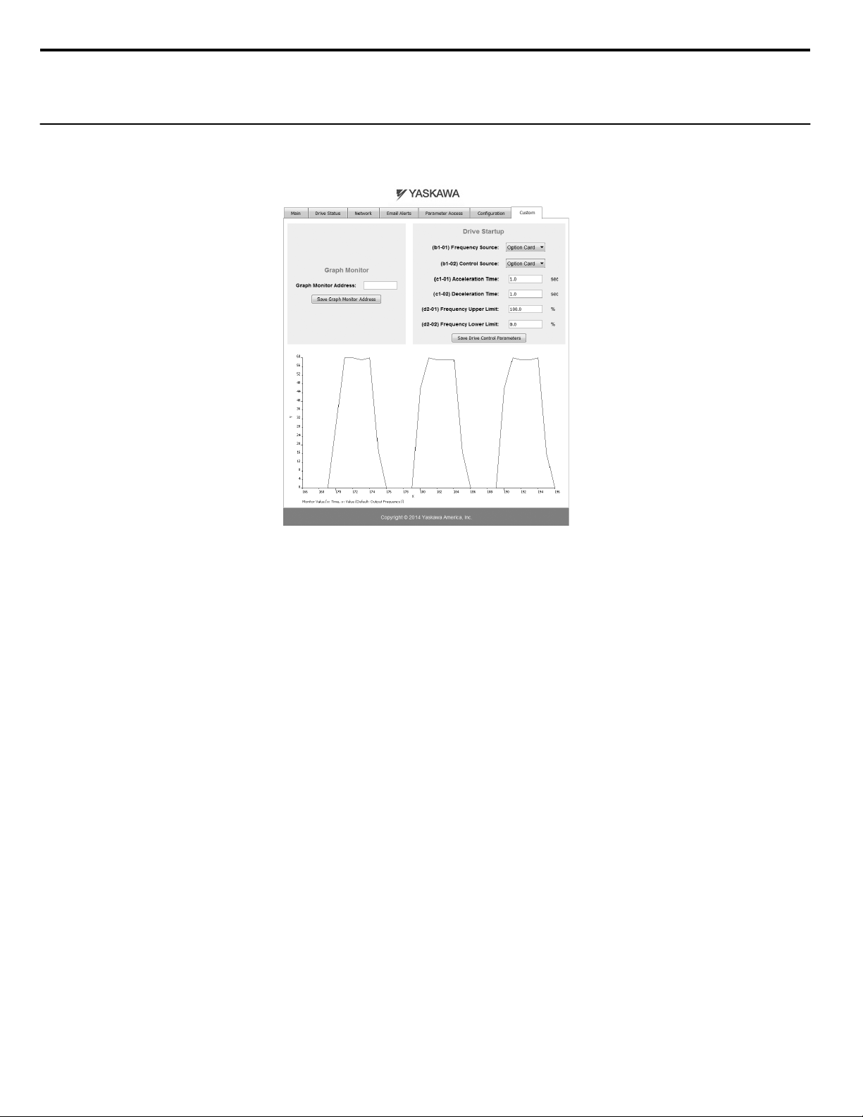
12 Web Interface
General Settings
n
Click “Save Options Card Parameters” to save the Applet Refresh Rate and the Parameter Security settings to the option.
u
Custom Tab
The Custom tab displays a selection of quick setting parameters.
Figure 18 Custom Tab View
58
YASKAWA SIEP YAICOM 16A 1000-Series Option Dual-Port EtherNet/IP SI-EN3D Technical Manual
Page 59
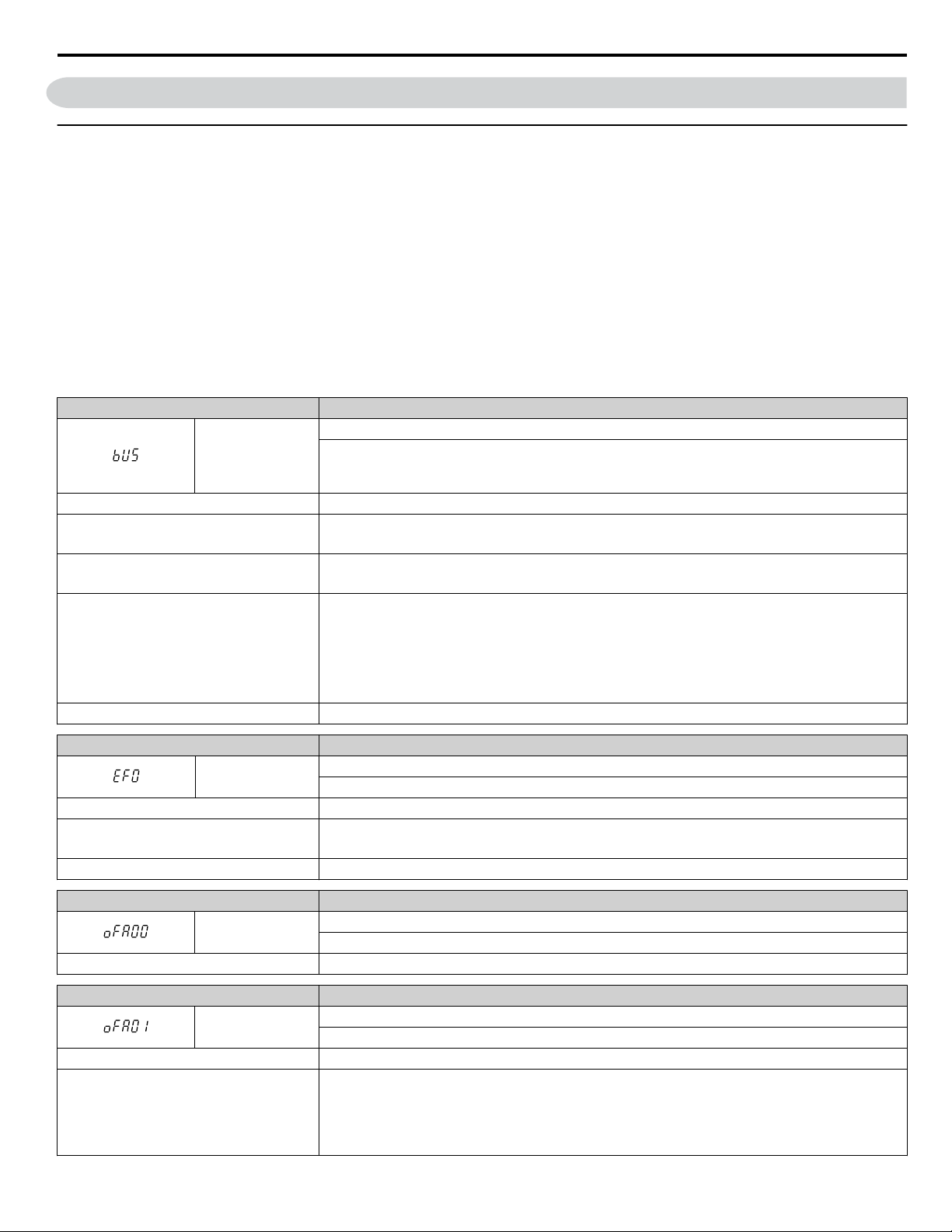
13 Troubleshooting
13 Troubleshooting
u
Drive-Side Error Codes
Drive-side error codes appear on the drive digital operator. Causes of the errors and corrective actions are listed below. Refer
to the drive manual for additional error codes that may appear on the drive digital operator.
Faults
n
Both bUS (Option Communication Error) and EF0 (Option Card External Fault) can appear as an alarm or as a fault. When a
fault occurs, the digital operator ALM LED remains lit. When an alarm occurs, the ALM LED flashes.
If communication stops while the drive is running, use the following questions as a guide to help remedy the fault:
• Is the option properly installed?
• Are the communication lines properly connected to the option? Are the wires loose?
• Is the controller program working? Has the controller/PLC CPU stopped?
• Did a momentary power loss interrupt communications?
Digital Operator Display Fault Name
Option Communication Error
bUS
Cause Possible Solution
Master controller (PLC) has stopped
communicating
Communication cable is not connected
properly
A data error occurred due to noise
Option is damaged If there are no problems with the wiring and the error continues to occur, replace the option.
• The connection was lost after establishing initial communication.
• Only detected when the Run command or frequency reference is assigned to the option (b1-01 = 3 or
b1-02 = 3).
• Check that power is supplied to the PLC
• Check that PLC is not in program mode
• Check for faulty wiring
• Correct any wiring problems
• Check the various options available to minimize the effects of noise
• Counteract noise in the control circuit, main circuit, and ground wiring
• If a magnetic contactor is identified as a source of noise, install a surge absorber to the contactor coil
• Make sure the cable used meets requirements
• Make sure the option ground wire is connected between option FE terminal and the drive ground
terminal connected to earth ground
Digital Operator Display Fault Name
EF0
Cause Possible Solutions
An external fault was received from the PLC
and F6-03 is set to a value other than 3.
Problem with the PLC program Check the PLC program and correct problems.
Digital Operator Display Fault Name
oFA00
Cause Possible Solution
Digital Operator Display Fault Name
oFA01
Cause Possible Solution
The option card connection to port CN5-A is
faulty
Option Card External Fault
The alarm function for an external device has been triggered.
• Remove the cause of the external fault.
• Remove the external fault input from the PLC.
Option Card Connection Error at Option Port CN5-A
Option compatibility error
Option Card Fault at Option Port CN5-A
Option not properly connected
• Turn off the power and reconnect the option card.
• Check if the option card is properly plugged into the option port. Make sure the card is fixed properly.
• If the option is not a communication option card, try to use the card in a different option port. If the
option card works properly in a different option port, CN5-A is damaged, and the drive requires
replacement. If the error persists (oFb01 or oFC01 occur), replace the option card.
YASKAWA SIEP YAICOM 16A 1000-Series Option Dual-Port EtherNet/IP SI-EN3D Technical Manual
59
Page 60

13 Troubleshooting
Digital Operator Display Fault Name
to
,
to
to
Option card or hardware is damaged
Digital Operator Display Fault Name
The option card installed into port CN5-B is
incompatible with the drive
A communication option card has been
installed in option port
CN5-B
Digital Operator Display Fault Name
An option card of the same type is already
installed in option port CN5-A
An input option card is already installed in
option port CN5-A
oFA03 to oFA06
oFA10, oFA11
oFA12 to oFA17 Option Card Connection Error (CN5-A)
oFA30 to oFA43 Communication Option Card Connection Error (CN5-A)
Cause Possible Solution
oFb00
Cause Possible Solution
oFb02
Cause Possible Solution
Option Card Error Occurred at Option Port CN5-A
• Cycle power to the drive.
• If the problem continues, replace the control board or the entire drive. Contact Yaskawa or a Yaskawa
representative for instructions on replacing the control board.
Option Card Fault at Option Port CN5-B
Option compatibility error
Confirm that the drive supports the option card to be installed.
Refer to Option Compatibility on page 62 for details. Contact Yaskawa for assistance.
Communication option cards are only supported by option port CN5-A. It is not possible to install more
than one communication option.
Option Card Fault at Option Port CN5-B
Same type of option card is currently connected
Except for PG options, only one of each option card type can only be installed simultaneously. Make sure
only one type of option card is connected.
Refer to Option Compatibility on page 62 for details. Contact Yaskawa for assistance.
Install a communication option, a digital input option, or an analog input option. More than one of the
same type of card cannot be installed simultaneously.
Digital Operator Display Fault Name
oFC00
Cause Possible Solution
The option card installed into port CN5-C is
incompatible with the drive
A communication option card has been
installed in option port
CN5-C
Digital Operator Display Fault Name
oFC02
Cause Possible Solution
An option card of the same type is already
installed in option port CN5-A or CN5-B.
An input option card is already installed in
option port CN5-A or CN5-B.
Option Card Connection Error at Option Port CN5-C
Option compatibility error
Confirm that the drive supports the option card to be installed.
Refer to Option Compatibility on page 62 for details. Contact Yaskawa for assistance.
Communication option cards are only supported by option port CN5-A. It is not possible to install more
than one communication option.
Option Card Fault at Option Port CN5-C
Same type of option card is currently connected
Except for PG options, only one of each option card type can only be installed simultaneously. Make sure
only one type of option card is connected.
Install a communication option, a digital input option, or an analog input option. More than one of the
same type of card cannot be installed simultaneously.
60
YASKAWA SIEP YAICOM 16A 1000-Series Option Dual-Port EtherNet/IP SI-EN3D Technical Manual
Page 61

13 Troubleshooting
Minor Faults and Alarms
n
Digital Operator Display Minor Fault Name
CALL
Cause Possible Solutions
Communications wiring is faulty, there is a
short circuit, the wiring is incorrect, or the
connections are poor.
Programming error on the master side. Check communications at start-up and correct programming errors.
Communications circuitry is damaged.
Termination resistor setting is incorrect.
bUS Fault Tolerance
n
Serial Communication Transmission Error
Communication has not yet been established.
• Check for wiring errors.
• Correct the wiring.
• Check for disconnected cables and short circuits. Repair as needed.
• Perform a self-diagnostics check.
• If the problem continues, replace the control board or the entire drive. Contact
Yaskawa for instructions on replacing the control board.
Install a termination resistor at both ends of a communication line. Set the internal
termination resistor switch correctly on slave drives. Place DIP switch S1 to the
ON position.
Minor Fault
(H2-oo = 10)
YES
bUS Fault Auto-Restart
Parameter F6-14, bUS Fault Auto Reset Select, will appear when the option is installed.
Setting F6-14 = 0 (Disabled) or F6-01 = 3 or greater (Alarm only) will not affect standard default drive behavior.
Setting F6-14 = 1 (Enabled) AND F6-01 ≠ 3 (Fault) will cause the following operation: The bUS fault occurs after the F7-16
delay and the Run command is removed from the drive. Then the option throws a bUS fault to the drive. When the condition
is removed, the option commands a fault reset and returns control of the drive to the EtherNet/IP network.
Note: The option will only read parameter F6-01 and F6-14 from the drive during power-up.
bUS Fault Delay
Parameter F7-16, Communications Loss Detection Time Delay, will appear when the option is installed.
The setting value of F7-16 is the length of time that the option will delay sending the bUS fault to the drive.
The status LEDs on the option are not affected by the delay time set in F7-16; the LEDs will indicate the bUS condition
immediately.
Note: The option will only read parameter F7-16 from the drive during power-up.
Explicit Message Communications Errors
n
When there is a problem with a request message sent from the master in explicit communications, the drive will return one of
the following error codes.
Table 14 Communications Errors and Solutions
Error
Code
(Hex)
08 Service not supported The service code is incorrect. Correct the service code.
09 Invalid attribute value The attribute is incorrect. Correct the attribute.
0C Object state conflict
0E Attribute not settable Attempted to change a read-only attribute. Correct the service code or attribute setting.
13 Not enough data The data size is incorrect. Correct the data size.
14 Attribute not supported
15 Too much data The data size is incorrect. Correct the data size.
16 Object does not exist An unsupported object was specified. Correct the class or instance setting.
1F Vendor-specific error
Description Cause Possible Solution
Attempted to change a drive constant that cannot be
changed while the drive is running.
Attempted to execute a service not defined for the
attribute.
Attempted to change a drive constant that cannot be
changed while the drive is running.
Attempted to change a drive constant to a value outside
the setting range.
Stop the drive.
Correct the service code or attribute setting.
Stop the drive.
Specify a value within the setting range.
YASKAWA SIEP YAICOM 16A 1000-Series Option Dual-Port EtherNet/IP SI-EN3D Technical Manual
61
Page 62

13 Troubleshooting
Error
Code
(Hex)
20 Invalid parameter
Description Cause Possible Solution
Attempted to change to a data value outside the setting
range.
Specify a data value within the setting range.
Note: Refer to the MEMOBUS/Modbus Data Table in the MEMOBUS/Modbus Communications chapter of the drive manual for a list of monitor
u
Option Error Codes
Option Fault Monitors U6-98 and U6-99
n
data using the MEMOBUS/Modbus message area.
The option can declare error/warning conditions via drive monitor parameters on the drive digital operator as shown in Table
15.
Table 15 Option Fault Monitor Descriptions
Fault Condition Fault Declared
No Fault n/a 0 No faults
Force Fault EF0 3
Network Link Down BUS ERROR 1100 No network link to option.
Connection Timeout BUS ERROR 1101 The node timer (Requested Packet Interval) timed out.
Duplicate IP Address BUS ERROR 1102
Default MAC Address None 1103
Status Value
(U6-98/U6-99)
Description
Network sent a message to force this node to the fault
state.
This node and at least one other node have the same IP
Address.
Factory default MAC Address programmed into the
option. Return for reprogramming.
Two drive monitor parameters, U6-98 and U6-99 assist the user in network troubleshooting.
• U6-98 displays the first declared fault since the last power cycle. U6-98 is only cleared upon drive power-up.
• U6-99 displays the present option status. U6-99 is cleared upon a network-issued fault reset and upon power-up.
If another fault occurs while the original fault is still active, parameter U6-98 retains the original fault value and U6-99 stores
the new fault status value.
u
Option Compatibility
A limited number of options may be simultaneously connected to the drive depending on the type of option.
Table 16 below lists the number of options that can be connected to the drive and the drive ports for connecting those options.
Table 16 Option Installation
Option Port/Connector Number of Options Possible
PG-B3, PG-X3 CN5-C
<2> <3>
PG-F3
AO-A3, DO-A3 CN5-A, B, C 1
<3>
SI-B3
<3>
ES3
<4>
DI-A3
<1> When connecting two PG option cards, use both CN5-B and CN5-C. When connecting only one PG option card, use the CN5-C connector.
<2> Not available for the application with Motor 2 Selection.
<3> Not available with models 4A0930 and 4A1200.
<4> When using AI-A3 and DI-A3 as monitors, the card can be connected to any of CN5-A, CN5-B or CN5-C. The input status of AI-A3 can then be
viewed using U1-21, U1-22, and U1-23, and the input status of DI-A3 can then be viewed using U1-17.
, PG-RT3
, SI-C3, SI-EN3
, SI-ET3
<2> <3>
<3>
<3>
, SI-N3, SI-P3, SI-S3, SI-T3, SI-W3
, SI-EN3D, SI-EM3
<3>
, SI-EP3
<3>
<3>
, AI-A3
, SI-
<4>
CN5-C 1
,
CN5-A 1
2
<1>
62
YASKAWA SIEP YAICOM 16A 1000-Series Option Dual-Port EtherNet/IP SI-EN3D Technical Manual
Page 63

14 Specifications
Item Specification
Model SI-EN3D
14 Specifications
Table 17 Option Specifications
Supported Messages
I/O Assembly Instance
SI-EN3D Specification Composite Test Revision: CT11 Passed
SI-EN3D Profile AC Drive
Connector Type RJ45 8-pin Straight Connector STP Cat5e cable
Physical Layer Type
IP Address Setting Programmable from drive keypad or network
Communication Speed
Number of Connections
Duplex Mode Half-forced, Auto-negotiate, Full-forced
Address Startup Mode Static, BOOTP, DHCP
Ambient Temperature -10 °C to +50 °C (14 °F to 122 °F)
Humidity 95% RH or lower with no condensation
Storage Temperature -20 °C to +60 °C (-4 °F to +140 °F) allowed for short-term transport of the product
Area of Use Indoor (free of corrosive gas, airborne particles, etc.)
Altitude 1000 m (3280 ft.) or lower
Explicit: Explicit Class 3, Unconnected
I/O: Class 1, Listen Only, Input Only
Input: 8 types (4 to 44 Bytes)
Output: 8 types (4 to 44 Bytes)
Isolated Physical Layer
TCP Protocol Transformer Isolated
Programmable from drive keypad or network:
10/100 Mbps, auto-negotiate
I/O: 2
Explicit: 6
YASKAWA SIEP YAICOM 16A 1000-Series Option Dual-Port EtherNet/IP SI-EN3D Technical Manual
63
Page 64

14 Specifications
This Page Intentionally Blank
64
YASKAWA SIEP YAICOM 16A 1000-Series Option Dual-Port EtherNet/IP SI-EN3D Technical Manual
Page 65

This Page Intentionally Blank
YASKAWA SIEP YAICOM 16A 1000-Series Option Dual-Port EtherNet/IP SI-EN3D Technical Manual
65
Page 66

Revision History
MANUAL NO.
Example:
SIEP YAICOM 16
Published in U.S.A. May 2014 14-5
Date of
publication
Date of
original publication
Revision number
1
The revision dates and the numbers of the revised manuals appear on the bottom of the back cover.
Date of Publication
Revision
Number
Section Revised Content
May 2014 - - First Edition
66
YASKAWA SIEP YAICOM 16A 1000-Series Option Dual-Port EtherNet/IP SI-EN3D Technical Manual
Page 67

Page 68

YASKAWA AC Drive 1000-Series Option
EtherNet/IP
Technical Manual
YASKAWA AMERICA, INC.
2121 Norman Drive South, Waukegan, IL 60085, U.S.A.
Phone: 1-800-YASKAWA (927-5292) or 1-847-887-7000 Fax: 1-847-887-7310
http://www.yaskawa.com
DRIVE CENTER (INVERTER PLANT)
2-13-1, Nishimiyaichi, Yukuhashi, Fukuoka, 824-8511, Japan
Phone: 81-930-25-3844 Fax: 81-930-25-4369
http://www.yaskawa.co.jp
YASKAWA ELECTRIC CORPORATION
New Pier Takeshiba South Tower, 1-16-1, Kaigan, Minatoku, Tokyo, 105-6891, Japan
Phone: 81-3-5402-4502 Fax: 81-3-5402-4580
http://www.yaskawa.co.jp
YASKAWA ELÉTRICO DO BRASIL LTDA.
Avenida Piraporinha 777, Diadema, São Paulo, 09950-000, Brasil
Phone: 55-11-3585-1100
http://www.yaskawa.com.br
YASKAWA EUROPE GmbH
Hauptstrasse 185, 65760 Eschborn, Germany
Phone: 49-6196-569-300 Fax: 49-6196-569-398
http://www.yaskawa.eu.com
YASKAWA ELECTRIC KOREA CORPORATION
9F, Kyobo Securities Bldg., 26-4, Yeouido-dong, Yeongdeungpo-gu, Seoul, 150-737, Korea
Phone: 82-2-784-7844
http://www.yaskawa.co.kr
YASKAWA ELECTRIC (SINGAPORE) PTE. LTD.
151 Lorong Chuan, #04-02A, New Tech Park, 556741, Singapore
Phone: 65-6282-3003
http://www.yaskawa.com.sg
YASKAWA ELECTRIC (CHINA) CO., LTD.
12F, Carlton Bld., No.21 HuangHe Road, HuangPu District, Shanghai 200003, China
Phone: 86-21-5385-2200
http://www.yaskawa.com.cn
YASKAWA ELECTRIC (CHINA) CO., LTD. BEIJING OFFICE
Room 1011, Tower W3 Oriental Plaza, No. 1 East Chang An Ave.,
Dong Cheng District, Beijing, 100738, China
Phone: 86-10-8518-4086
YASKAWA ELECTRIC TAIWAN CORPORATION
9F, 16, Nanking E. Rd., Sec. 3, Taipei, 104, Taiwan
Phone: 886-2-2502-5003
YASKAWA INDIA PRIVATE LIMITED
#17/A Electronics City, Hosur Road Bangalore 560 100 (Karnataka), India
Phone: 91-80-4244-1900
http://www.yaskawaindia.in
Fax: 55-11-3585-1187
Fax: 82-2-784-8495
Fax: 65-6289-3003
Fax: 86-21-5385-3299
Fax: 86-10-8518-4082
Fax: 886-2-2505-1280
Fax: 91-80-4244-1901
YASKAWA AMERICA, INC.
In the event that the end user of this p roduct is to b e the military and said product is to be employed in any weapons systems or the manufa cture
thereof, the export will fall u nder th e relevant regulations as stipulated in the For eign Exchange and Foreign Trade Regulatio ns. Therefore, be sure
to follow all procedures and submit all relevant documentation accordin g to any a nd all rules, r egulations and laws th at may ap
Specifications are subject to change without notice for on going product modifica tions and improvements.
© 2014 YASKAWA AMERICA, INC. All rights reserved.
MANUAL NO. SIEP YAICOM 16A
Published in USA May 2014 14-5
ply.
 Loading...