

Page 1
SI-EN3 and SI-EN3/V EtherNet/IP Option
Product Demonstration Unit
Technical Manual
Document: TM.AFD.08 12/28/2010
Rev: 10-12
Page 2

1.0 Introduction
To effectively demo the EtherNet/IP kit requires three components:
- A1000 with SI-EN3 or V1000 with SI-EN3/V communication option card properly installed
- PC with DriveWizard
- EtherNet/IP demo case.
Ensure that the components are located close enough to each other to allow easy connections using the
supplied CAT-5 cables located in the EtherNet/IP demo. Plug the drive demo (EtherNet/IP card) into one of
the open RJ-45 jacks on the EtherNet/IP demo case (vertical left side jacks). Plug your PC into another open
RJ-45 jack. The specific jack does not matter. Plug both the drive demo and the EtherNet/IP demo into
120VAC wall outlets using their demo case power cables.
• Make sure the pre-installed CAT-5 cable running from the PLC to an RJ-45 jack is still installed. If not,
please replace it with the shortest length CAT-5 cable available.
• No “cross-over” cables are required as this EtherNet/IP demo has a built-in switch.
• Power must be applied to the EtherNet/IP demo case for the network switch to work. This is needed when
trying to set up the PC in section 2.2.
• No EDS files should be required for this demo. The PLC programming is complete and operational as
shipped from Yaskawa.
• Refer to the latest revision of application note AN.AFD.22 – dated 12/21/2010 for greater detail on setting
up SI-EN3 and SI-EN3/V with ControlLogix and CompactLogix controllers from Allen-Bradley.
• APPENDIX A contains screen shots of some sections of these instructions that may prove helpful in
demonstrating the demo.
2.0 Setup
The setup will now be discussed in detail.
2.1 Drive Demo Case
This DEMO is intended to support and demonstrate A1000 (SI-EN3) or V1000 (SI-EN3/V) AC Drives with
the EtherNet/IP option board properly installed. No special drive software is required. The HMI and
CompactLogix L32E programs are loaded and operational as shipped from Yaskawa.
The SI-EN3 or SI-EN3/V EtherNet/IP option card should be installed per the instructions contained in
TOEPYEACOM04 for the A1000 or TOEPYEACOM01 for the V1000.
» Lastly, set parameters b1-01 = 3 (Ref Source “Option PCB”) and b1-02 = 3 (Run Source “Option PCB” )
» This will allow the run command and frequency reference to come from the SI-EN3 or SI-EN3/V
EtherNet/IP option card.
®
Industrial with an Internet browser.
Note: The motor demo case (available separately) is not required but helpful in showing a large
audience that the drive is actually being controlled by the PLC.
Note: The card must have its default IP address (192.168.1.20) for the demo to work. If you are not
sure, follow the instructions in section 6 of the Installation or Technical Manuals of the respective
option card - F7-13 = 0 (IP Add Mode Sel “User Defined”)..
Page 2 of 8
Page 3

2.2 PC and an Internet Browser
Although a PC is not technically required to show EtherNet/IP communication with this demo, it is a
perfect opportunity to demonstrate the EtherNet/IP card’s webpage. Looking at the webpage also
confirms that the card is properly functioning.
Configure the PC’s IP address to be compatible with the EtherNet/IP card (use 192.168.1.19 as
instructed). Please make sure to write down the existing IP settings so you can properly re-connect to
your home/office network. You will have to return your PC’s IP settings to their original settings after the
EtherNet/IP demonstration.
Direct any Internet browser to the card by directly typing 192.168.1.20 into the search bar. The card’s web
page should pull up indicating a properly functioning PC and EtherNet/IP card.
Note: Do not re-configure the EtherNet/IP card. You should show the customer the configuration tab,
but do not make changes. If changes are made, please reset the card.
While leaving the Internet browser connection open, launch DriveWizard
®
Industrial as this contains the
latest features pertaining to Internet connections.
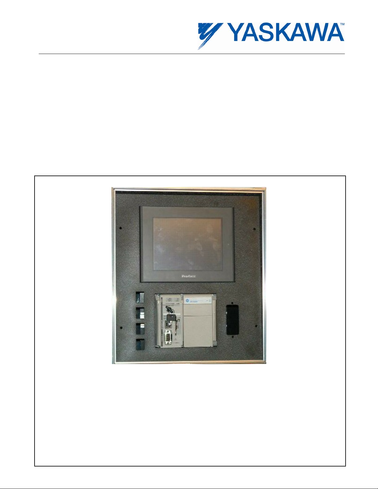
2.3 EtherNet/IP Demo Case
The EtherNet/IP demo case is designed to be very easy to operate. Make sure the drive demo is powered
and its Cat-5 EtherNet cable is connected to the EtherNet/IP demo case. After power is applied to the
EtherNet/IP demo case, the demo will need several minutes for the PLC and HMI touch screen to
complete their boot-up routines. After boot-up is complete, the HMI touch screen should have no errors
(should display “Drive Ready”) and show several buttons: Start, Stop, FWD/REV, Running Status, and 3
Monitors. Section 3 of this manual will discuss the manipulation of the EtherNet/IP demo. Specific
discussion points regarding EtherNet/IP will be discussed in section 4 of this manual.
3.0 Demonstrating EtherNet Connectivity
Use the HMI touch screen to set a frequency reference by tapping on the frequency reference numeric
display. This will bring up a numeric keypad. Use the CLR button to zero out the existing reference. Next set a
frequency reference between 2.0 and 60.0 Hz. Finish by tapping the ENT key.
You should now be able to start, stop and change the direction of the motor using the appropriate buttons on
the touch screen. The monitors should reflect your actions. The customer needs to understand that the HMI is
communicating your actions to the PLC using the EtherNet/IP protocol over standard EtherNet hardware
(switch, CAT-5 cable, etc.). The PLC in turn is communicating your actions to the drive using the EtherNet/IP
protocol.
While you are using the touch screen to control the drive, pull up the drive’s webpage on the PC. Select the
“Drive Diagnostics” button to display 15 of the drive’s monitors. These monitors should reflect your actions of
starting, stopping, and reversing the drive.
The latest rev of DriveWizard
®
Industrial software can also be opened up on your PC and connected to one of
the four ports on the demo to demonstrate remote access as well. This ability to control and monitor remotely
from multiple sources is radically different from all non-EtherNet interfaces. For the first time, it is practical
(and relatively easy) to monitor drives located around the globe from a single office.
Page 3 of 8
Page 4

4.0 Specific Points to Get Across
When demonstrating the various components of this demo, please try to push the following points. These are
listed in no order of importance.
4.1 Drive’s Webpage
- Content is stored in the card itself.
- Any web browser can access the webpage.
- Web pages are in their infancy. Look for more powerful pages in the coming years.
- We are investigating adding a password to prevent the changing of the IP address remotely. This
should alleviate some of the security concerns.
4.2 DriveWizard
®
Industrial – download the latest revision on your PC for this part of the demo
- You should familiarize yourself with the “Drive Selection & Communication Setup” tab/section of
DriveWizard
®
Industrial before proceeding with this portion of the demonstration. See APPENDIX A
screen shot.
- Like the webpage, DriveWizard
- DriveWizard
®
uses a spreadsheet to store multiple preset IP addresses seen in the drop-down box in
®
over EtherNet can connect to a drive anywhere in the world.
the Communications ⇒ Setup screen shown above. For ease of use, fill out the spreadsheet using
MS Excel. The file is located in C:\Program Files\Yaskawa\Drive Wizard. The file is called IPList.csv.
Make sure to leave the file in the “.csv” format.
- Using EtherNet, the graphing function supports a 100ms sample rate that is not present through the
keypad port connection. Be aware that the 100ms sample rate is PC CPU intensive.
- You can open multiple instances of DriveWizard
®
on the same PC. This allows you to monitor multiple
drives on the EtherNet network at the same time if so desired.
4.3 EtherNet/IP
- EtherNet/IP is based on CIP (Common Industrial Protocol). This is the same backbone that
DeviceNet and ControlNet are based on. This means that programmers familiar with DeviceNet or
ControlNet will pick up EtherNet/IP quickly. It also allows a PLC connected to different networks (i.e.
EtherNet/IP and DeviceNet) to pass data between the networks very quickly (act as a bridge).
- EtherNet/IP is a very fast network (100Mbps). Moreover, it is a scheduled network. Unlike PC
networks and Modbus TCP/IP, EtherNet/IP is a scheduled network, which prevents collisions thus
improving throughput.
- EtherNet/IP is becoming a dominant industrial network protocol. EtherNet/IP is very flexible and
extremely fast. With CIP as its backbone, existing Allen-Bradley PLC users of DeviceNet and
ControlNet can easily learn the EtherNet/IP protocol.
- Determinism. This is a tricky subject. Determinism is a guarantee that data will make it to its
destination in a defined amount of time. The time might be 3 seconds or 5ms. The EtherNet/IP
protocol is not deterministic in the sense that its scheduling algorithm is not based on a deterministic
routine. Also, all EtherNet protocols can suffer from the nearly infinite network configurations. An
industrial EtherNet network should not be on the same network as say an office print server. All this
being said, however, EtherNet/IP is essentially deterministic for most implementations. Tests run at
Yaskawa on a heavily loaded drive network show that EtherNet/IP was deterministic to under 5ms,
which is faster than our drive can process network data. So while EtherNet/IP is not deterministic for
the intrinsically safe definition, it is deterministic and extremely fast for most applications.
Page 4 of 8
Page 5

5.0 Network Comparison Table
Feature Modbus TCP/IP EtherNet/IP DeviceNet
Part Number SI-EM3 SI-EN3 SI-N3
Network Type Request / Response Produced / Consumed I/O
Protocol Type Controller Level Device Level
Speed 10/100Mbps 125-500kpbs
Nodes Unlimited 64
Number of Masters Multiple 1
Webpage Yes No
Deterministic No Essentially No
Configuration Files No EDS Files
Simultaneous
Connections
Automatic Node
Replacement
Parameter Access MSTR Function Explicit Messaging
10 8 2
None Built-in ADR
Page 5 of 8
Page 6

APPENDIX A
This section contains some helpful screen shots of details referenced above.
Ethernet I/P Demonstration Unit
Set Up and Configuration
Ethernet Demo Connections
SI-EN3 Option
Parameters To Adjust
» b1-01 = 3 (Ref Source “Option PCB”)
» b1-02 = 3 (Run Source “Option PCB”)
» F7-13 = 0 (IP Add Mode Sel “User Defined”)
PP.YAI-NSM-COM .01 | Rev 1.00 | Date: 12/14/2010 | © 2010 Yaskawa Electric America, Inc. All rights reserved.
Ethernet I/P Demonstration Unit
Image Place Holder
Page 12
Using the Ethernet Dem o
Start, Run drive Fwd at 60 Hz
Touch Screen Input Switches
» Switch 1, External Fault (EF3)
» Switch 2, Fault Reset
» Switch 3, Analog Input (A3 on A1000 Demo)
» Switch 4, Freq Ref from A1000 (d1-03)
» Switch 5, Jog R ef, 6Hz ( d1- 17)
» Switch 6, Base Block
PP.YAI-NSM-COM .01 | Rev 1.00 | Date: 12/14/2010 | © 2010 Yaskawa Electric America, Inc. All rights reserved.
Image Place Holder
Page 13
Page 6 of 8
Page 7

1000 Series Webpage (SI-EN3)
Image Place Holder
PP.YAI-NSM-COM.01 | Rev 1.00 | Date: 12/14/2010 | © 2010 Yaskawa Electric America, Inc. All rights reserved.
1000 Series Webpage (SI-EN3)
Image Place Holder
Page 1
PP.YAI-NSM-CO M. 0 1 | Rev 1.00 | Date: 12/14/20 1 0 | © 2010 Yaskaw a Electric America, Inc. All r ights r eser ved.
Page 15
Page 7 of 8
Page 8

1000 Series Webpage (SI-EN3)
Image Place Holder
PP.YAI-NSM-COM.01 | Rev 1.00 | Date: 12/14/2010 | © 2010 Yaskawa Electric America, Inc. All rights reserved.
Page 16
Page 8 of 8
 Loading...