

Page 1
YASKAWA AC Drive V1000 Option
Modbus TCP/IP
Installation Manual
Type: SI-EM3D/V
To properly use the product, read this manual thoroughly and retain
for easy reference, inspection, and maintenance. Ensure the end
user receives this manual.
TM
MANUAL NO. TOEP YAICOM 17A
Page 2

Copyright © 2014 YASKAWA AMERICA, INC. All rights reserved.
All rights reserved. No part of this publication may be reproduced, stored in a retrieval system,
or transmitted, in any form or by any means, mechanical, electronic, photocopying, recording,
or otherwise, without the prior written permission of Yaskawa. No patent liability is assumed
with respect to the use of the information contained herein. Moreover, because Yaskawa is
constantly striving to improve its high-quality products, the information contained in this
manual is subject to change without notice. Every precaution has been taken in the preparation
of this manual. Yaskawa assumes no responsibility for errors or omissions. Neither is any
liability assumed for damages resulting from the use of the information contained in this
publication.
Page 3

Table of Contents
1 PREFACE AND SAFETY.....................................4
2 PRODUCT OVERVIEW........................................9
3 RECEIVING.......................................................10
4 OPTION COMPONENTS....................................11
5 INSTALLATION PROCEDURE...........................16
6 RELATED DRIVE PARAMETERS......................30
7 MODBUS TCP/IP MESSAGING..........................34
8 WEB INTERFACE..............................................40
9 RAPID SPANNING TREE PROTOCOL...............46
10 TROUBLESHOOTING........................................47
11 SPECIFICATIONS.............................................51
YASKAWA TOEP YAICOM 17A V1000 Option Dual-Port Modbus TCP/IP SI-EM3D/V Installation Manual
3
Page 4
1 Preface and Safety
1 Preface and Safety
Yaskawa manufactures products used as components in a wide variety of industrial systems
and equipment. The selection and application of Yaskawa products remain the responsibility
of the equipment manufacturer or end user. Yaskawa accepts no responsibility for the way its
products are incorporated into the final system design. Under no circumstances should any
Yaskawa product be incorporated into any product or design as the exclusive or sole safety
control. Without exception, all controls should be designed to detect faults dynamically and
fail safely under all circumstances. All systems or equipment designed to incorporate a product
manufactured by Yaskawa must be supplied to the end user with appropriate warnings and
instructions as to the safe use and operation of that part. Any warnings provided by Yaskawa
must be promptly provided to the end user. Yaskawa offers an express warranty only as to the
quality of its products in conforming to standards and specifications published in the Yaskawa
manual. NO OTHER WARRANTY, EXPRESS OR IMPLIED, IS OFFERED. Yaskawa
assumes no liability for any personal injury, property damage, losses, or claims arising from
misapplication of its products.
u
Applicable Documentation
The following manuals are available for the SI-EM3D/V option:
Yaskawa AC Drive V1000 Option SI-EM3D/V Dual-Port Modbus TCP/IP Installation
Manual (TOEPYAICOM17)
The Installation Manual contains information required to install the option and set up
related drive parameters.
Yaskawa AC Drive V1000 Option SI-EM3D/V Dual-Port Modbus TCP/IP Technical
Manual (SIEPYAICOM17)
The Technical Manual contains detailed information about the option. In the U.S., access
http://www.yaskawa.com to obtain the Technical Manual. Customers in other areas should
contact a Yaskawa representative.
V1000 Series AC Drive Quick Start Guide
This guide contains basic information required to install and wire the drive. It also gives
an overview of fault diagnostics, maintenance, and parameter settings. The purpose of this
guide is to prepare the drive for a trial run with an application and for basic operation. This
manual is available for download on our documentation website, www.yaskawa.com.
V1000 Series AC Drive Technical Manual
This manual provides detailed information on parameter settings, drive functions, and
MEMOBUS/Modbus specifications. Use this manual to expand drive functionality and to
take advantage of higher performance features. This manual is available for download on
our documentation website, www.yaskawa.com.
4
YASKAWA TOEP YAICOM 17A V1000 Option Dual-Port Modbus TCP/IP SI-EM3D/V Installation Manual
Page 5
1 Preface and Safety
u
Terms
Note: Indicates supplemental information that is not related to safety messages.
Drive: Yaskawa V1000 Series AC Drive
Option: Yaskawa AC Drive V1000 SI-EM3D/V Dual-Port Modbus TCP/IP Option
u
Registered Trademarks
• Modbus TCP/IP is a trademark of Modbus-IDA.
• All trademarks are the property of their respective owners.
u
Supplemental Safety Information
Read and understand this manual before installing, operating, or servicing this option. The
option must be installed according to this manual and local codes.
The following conventions are used to indicate safety messages in this manual. Failure to heed
these messages could result in serious or possibly even fatal injury or damage to the products
or to related equipment and systems.
DANGER
Indicates a hazardous situation, which, if not avoided, will result in death or serious
injury.
WARNING
Indicates a hazardous situation, which, if not avoided, could result in death or serious
injury.
WARNING! may also be indicated by a bold key word embedded in the text followed by an italicized safety
message.
CAUTION
Indicates a hazardous situation, which, if not avoided, could result in minor or
moderate injury.
CAUTION! may also be indicated by a bold key word embedded in the text followed by an italicized safety
message.
YASKAWA TOEP YAICOM 17A V1000 Option Dual-Port Modbus TCP/IP SI-EM3D/V Installation Manual
5
Page 6
1 Preface and Safety
NOTICE
Indicates a property damage message.
NOTICE: may also be indicated by a bold key word embedded in the text followed by an italicized safety
message.
General Safety
n
General Precautions
• The diagrams in this manual may be indicated without covers or safety shields to show details. Replace
the covers or shields before operating the drive and run the drive according to the instructions
described in this manual.
• Any illustrations, photographs, or examples used in this manual are provided as examples only and
may not apply to all products to which this manual is applicable.
• The products and specifications described in this manual or the content and presentation of the manual
may be changed without notice to improve the product and/or the manual.
• When ordering a new copy of the manual due to damage or loss, contact your Yaskawa representative
or the nearest Yaskawa sales office and provide the manual number shown on the front cover.
• If nameplate becomes worn or damaged, order a replacement from your Yaskawa representative or
the nearest Yaskawa sales office.
DANGER
Heed the safety messages in this manual.
Failure to comply will result in death or serious injury.
The operating company is responsible for any injuries or equipment damage resulting from
failure to heed the warnings in this manual.
Electrical Shock Hazard
Do not connect or disconnect wiring while the power is on.
Failure to comply will result in death or serious injury.
Failure to comply will result in death or serious injury. Before servicing, disconnect all
power to the equipment. The internal capacitor remains charged even after the power supply
is turned off. The charge indicator LED will extinguish when the DC bus voltage is below
50 Vdc. To prevent electric shock, wait for at least the time specified on the warning label
once all indicators are OFF, and then measure the DC bus voltage level to confirm it has
reached a safe level.
6
YASKAWA TOEP YAICOM 17A V1000 Option Dual-Port Modbus TCP/IP SI-EM3D/V Installation Manual
Page 7
V1000
Warning
information
AVERTISSEMENT
Lire le manuel avant l'installation.
Attendre 5 minutes apres la coupure de l'alimentation,
pour permettre la decharge des condensateurs.
Pour repondre aux exigences , s assurer que le
neutre soit relie a la terre, pour la serie 400V.
WARNING
Read manual before installing.
Wait 5 minutes for capacitor discharge after
disconnecting power supply.
To conform to requirements, make sure
to ground the supply neutral for 400V class.
Risk of electric shock.
Risque de decharge
electrique.
1 Preface and Safety
NOTICE
Observe proper electrostatic discharge procedures (ESD) when handling the drive and
circuit boards.
Failure to comply may result in ESD damage to the drive circuitry.
Do not perform a withstand voltage test on any part of the drive.
Failure to comply could result in damage to the sensitive devices within the drive.
Do not operate damaged equipment.
Failure to comply could result in further damage to the equipment.
Do not connect or operate any equipment with visible damage or missing parts.
Do not expose the drive to halogen group disinfectants.
Failure to comply may cause damage to the electrical components in the drive.
Do not pack the drive in wooden materials that have been fumigated or sterilized.
Do not sterilize the entire package after the product is packed.
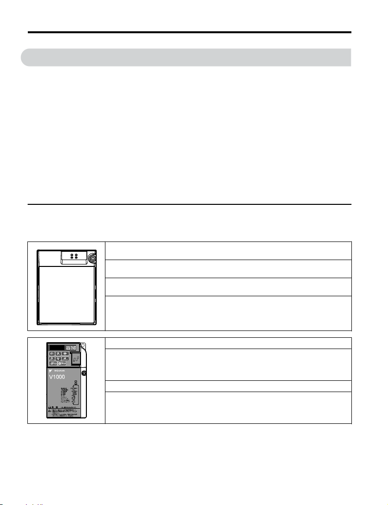
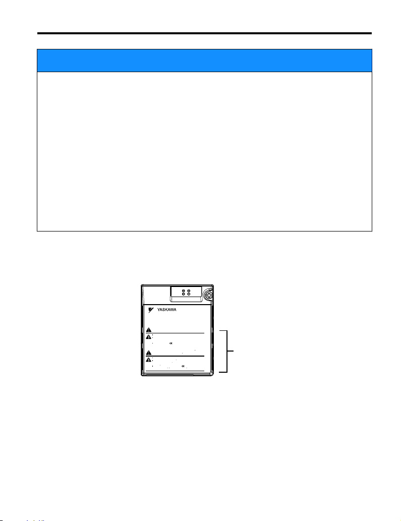
Option Unit Warning Labels
n
Warning information is displayed on the option unit as shown in the figure below. Follow all
warnings and safety instructions when using the product.
YASKAWA TOEP YAICOM 17A V1000 Option Dual-Port Modbus TCP/IP SI-EM3D/V Installation Manual
7
Page 8
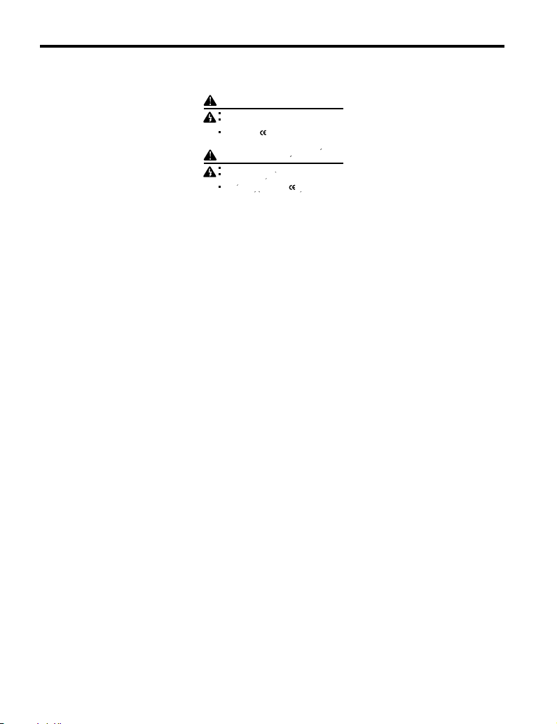
AVERTISSEMENT
Lire le manuel avant l'installation.
Attendre 5 minutes apres la coupure de l'alimentation,
pour permettre la decharge des condensateurs.
Pour repondre aux exigences , s assurer que le
neutre soit relie a la terre, pour la serie 400V.
WARNING
Read manual before installing.
Wait 5 minutes for capacitor discharge after
disconnecting power supply.
To conform to requirements, make sure
to ground the supply neutral for 400V class.
Risk of electric shock.
Risque de decharge
electrique.
1 Preface and Safety
Warning Contents
n
8
YASKAWA TOEP YAICOM 17A V1000 Option Dual-Port Modbus TCP/IP SI-EM3D/V Installation Manual
Page 9
2 Product Overview
2 Product Overview
u
About this Product
This option provides a communications connection between the drive and a Modbus TCP/IP
network. The option connects the drive to a Modbus TCP/IP network and facilitates the
exchange of data.
This manual explains the handling, installation and specifications of this product.
The option is a communications link to connect industrial devices (such as smart motor
controllers, operator interfaces, and variable frequency drives) as well as control devices (such
as programmable controllers and computers) to a network. The option is a simple, networking
solution that reduces the cost and time to wire and install factory automation devices, while
providing interchangeability of like components from multiple vendors.
By installing the option to a drive, it is possible to do the following from a Modbus TCP/IP
master device:
• Operate the drive
• Monitor drive status
• Change drive parameter settings.
u
Applicable Models
The option can be used with the drive models in Table 1.
Table 1 Applicable Models
Drive Series
V1000
<1> See “PRG” on the drive nameplate for the software version number.
Drive Model Number
CIMR-VooAoooo
Software Version
1012 and later
<1>
YASKAWA TOEP YAICOM 17A V1000 Option Dual-Port Modbus TCP/IP SI-EM3D/V Installation Manual
9
Page 10
MANUAL
3 Receiving
3 Receiving
Please perform the following tasks upon receipt of the option:
• Inspect the option for damage. Contact the shipper immediately if the option appears
damaged upon receipt.
• Verify receipt of the correct model by checking the model number printed on the name
plate of the option package.
• Contact your supplier if you have received the wrong model or the option does not function
properly.
u
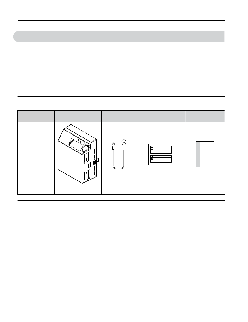
Option Package Contents
Description Option Unit Ground Wire Warning Labels
–
Quantity 1 4 1 1
u
Tools Required for Installation
Installation
Manual
A Phillips screwdriver (M3, M3.5 to M6 metric or #1, #2 U.S. standard) is required to install
the option. Screw sizes vary by drive capacity. Select a screwdriver appropriate for the drive
capacity.
Note: Tools required to prepare the option cables for wiring are not listed in this manual.
10
YASKAWA TOEP YAICOM 17A V1000 Option Dual-Port Modbus TCP/IP SI-EM3D/V Installation Manual
Page 11
4 Option Components
A
B
C
H
E
D
H
G
I
J
R
F
Q
00000000000000
SI-EN3D/V
1XXX
P
N
K
M
O L
Option with cover removed
Underside
Option with cover attached
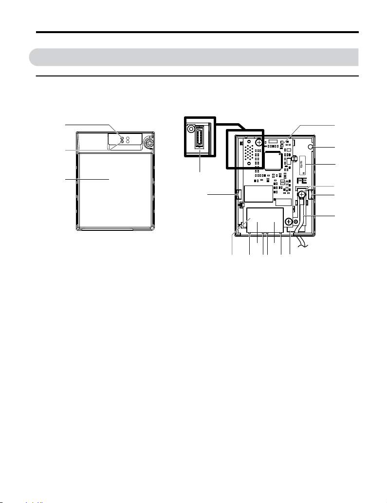
u
SI-EM3D/V Dual-Port Modbus TCP/IP Option Unit
4 Option Components
J – Pass-through hole for
ground wire
K –
Port 2 LED (10/100)
L – Port 2
M –
Port 2 LED (LINK/ACT)
<2>
N –
Port 1 LED (10/100)
O – Port 1
P –
Port 1 LED (LINK/ACT)
<2>
Q – Modbus TCP/IP cable
connector
A –
B –
LED (MS)
LED (NS)
<2>
<2>
C – Option cover
D – Modbus TCP/IP PCB
E – Attachment screw hole
for option cover
F – Nameplate
G – Functional earth cable
connection (FE)
H – Mounting tab
I –
Ground wire
<1>
R – Option connector
Figure 1 Option Unit Components
<1> A selection of ground wires are packaged loose in the option shipping package. Connect the
appropriate ground wire based on drive model during installation.
<2> Refer to Option LED Display on page 14 for details on the LEDs.
YASKAWA TOEP YAICOM 17A V1000 Option Dual-Port Modbus TCP/IP SI-EM3D/V Installation Manual
<2>
<2>
11
Page 12
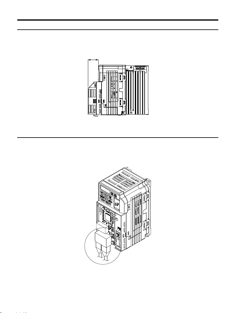
27 mm (1.06 in.)
4 Option Components
u
Dimensions
The installed option adds 27 mm (1.06 in.) to the total depth of the drive.
Figure 2 Dimensions
u
Communication Connector CN1
Communication Connector CN1 is a modular RJ45 female connector and the connection point
for a customer-supplied male Modbus network communication cable.
12
Figure 3 Communication Connector CN1 (RJ45)
YASKAWA TOEP YAICOM 17A V1000 Option Dual-Port Modbus TCP/IP SI-EM3D/V Installation Manual
Page 13
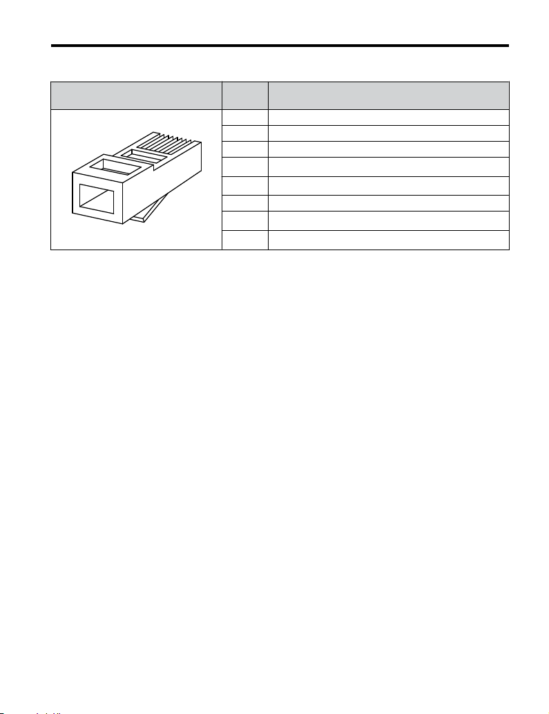
Latch release
1 2 3 4 5 6 7 8
4 Option Components
Table 2 Male, 8-Way Modular Connector (Customer-Supplied)
Male 8-Way Modular Connector Pin Description
1 (Pair 2) Transmit data (TXD) +
2 (Pair 2) Transmit data (TXD) -
3 (Pair 3) Receive data (RXD) +
4 (Pair 1)
5 (Pair 1)
6 (Pair 3) Receive data (RXD) -
7 (Pair 4)
8 (Pair 4)
<1> Not used for 10 Mbps and 100 Mbps networks.
Not used
Not used
Not used
Not used
<1>
<1>
<1>
<1>
YASKAWA TOEP YAICOM 17A V1000 Option Dual-Port Modbus TCP/IP SI-EM3D/V Installation Manual
13
Page 14
4 Option Components
u
Option LED Display
The option has four LEDs.
Bi-color Status LEDs:
• Module status (MS) red/green
• Network status (NS) red/green
Ethernet LEDs:
• Network speed - 10/100 (MS) green
• Link status and network activity - LINK/ACT (NS) red/green
The operational states of the option LEDs after completion of the power-up diagnostic LED
sequence are described in Table 3. Wait at least 2 seconds for the power-up diagnostic process
to complete before verifying LED states.
Table 3 Option LED States
Name
MS
NS
Display
Color Status
– OFF Power supply OFF Power is not being supplied to the drive.
Green ON Normal operation
Green Flashing Standby/Initializing
Red Flashing Non-fatal error occurred
Red ON Fatal error occurred
– OFF
Green ON
Green Flashing
Red ON Major fault
Operating Status Remarks
The option is operating normally and
initialization is complete.
The option is in process of configuring or
waiting for configuration information.
The option has detected a recoverable
minor fault such as incomplete
configuration.
The option has detected an unrecoverable
major fault.
Power supply OFF or no
network connection
established.
Online communications
established
Control communications
established
The option is online and has established
connections.
The option is online with a control
connection.
The option detected a duplicate IP address
or the control connection timed out.
–
14
YASKAWA TOEP YAICOM 17A V1000 Option Dual-Port Modbus TCP/IP SI-EM3D/V Installation Manual
Page 15

4 Option Components
Name
<1>
10/100
LINK/ACT
<1>
<1> Remove the cover to check the status of the LED. Be careful not to touch the main circuit terminals or the control
board in the drive.
Display
Color Status
Green OFF 10 Mbps is established
Green ON 100 Mbps is established
Green OFF LINK is not established
Green ON LINK is established
Green Flashing
Operating Status Remarks
LINK is established and
there is network activity.
–
YASKAWA TOEP YAICOM 17A V1000 Option Dual-Port Modbus TCP/IP SI-EM3D/V Installation Manual
15
Page 16
5 Installation Procedure
5 Installation Procedure
u
Section Safety
DANGER
Electrical Shock Hazard
Do not connect or disconnect wiring while the power is on.
Failure to comply will result in death or serious injury.
Disconnect all power to the drive and wait at least the amount of time specified on the drive
front cover safety label. After all indicators are off, measure the DC bus voltage to confirm
safe level, and check for unsafe voltages before servicing. The internal capacitor remains
charged after the power supply is turned off.
WARNING
Electrical Shock Hazard
Do not remove the option unit cover while the power is on.
Failure to comply could result in death or serious injury.
The diagrams in this section may include options and drives without covers or safety shields
to show details. Be sure to reinstall covers or shields before operating any devices. The
option should be used according to the instructions described in this manual.
Do not allow unqualified personnel to use equipment.
Failure to comply could result in death or serious injury.
Maintenance, inspection, and replacement of parts must be performed only by authorized
personnel familiar with installation, adjustment, and maintenance of this product.
Do not use damaged wires, stress the wiring, or damage the wire insulation.
Failure to comply could result in death or serious injury.
Do not use damaged wires, place excessive stress on wiring, or damage the wire
insulation.
Failure to comply could result in death or serious injury.
16
YASKAWA TOEP YAICOM 17A V1000 Option Dual-Port Modbus TCP/IP SI-EM3D/V Installation Manual
Page 17
5 Installation Procedure
WARNING
Fire Hazard
Tighten all terminal screws to the specified tightening torque.
Loose electrical connections could result in death or serious injury by fire due to overheating
of electrical connections.
NOTICE
Observe proper electrostatic discharge procedures (ESD) when handling the drive and
circuit boards.
Failure to comply may result in ESD damage to the drive circuitry.
Never shut the power off while the drive is outputting voltage.
Failure to comply may cause the application to operate incorrectly or damage the drive.
Do not operate damaged equipment.
Failure to comply may cause further damage to the equipment.
Do not connect or operate any equipment with visible damage or missing parts.
Do not use unshielded cable for control wiring.
Failure to comply may cause electrical interference resulting in poor system performance.
Use shielded twisted-pair wires and ground the shield to the ground terminal of the drive.
Properly connect all pins and connectors.
Failure to comply may prevent proper operation and possibly damage equipment.
Check wiring to ensure that all connections are correct after installing the option and
connecting any other devices.
Failure to comply could result in damage to the option.
YASKAWA TOEP YAICOM 17A V1000 Option Dual-Port Modbus TCP/IP SI-EM3D/V Installation Manual
17
Page 18

5 Installation Procedure
u
Prior to Installing the Option
Prior to installing the option, wire the drive, make necessary connections to the drive terminals,
and verify that the drive functions normally without the option installed. Refer to the drive
Quick Start Guide for information on wiring and connecting the drive.
u
Installing the Option
DANGER! DANGER! Electrical Shock Hazard. Do not connect or disconnect wiring while the power is on.
Failure to comply could result in death or serious injury. Before installing the option, disconnect all power to
the drive and wait at least the amount of time specified on the drive front cover safety label. After all indicators
are off, measure the DC bus voltage to confirm safe level, and check for unsafe voltages before servicing.
The internal capacitor remains charged after the power supply is turned off.
Shut off power to the drive, wait at least five minutes after confirming the DC bus
1.
voltage is safe, then loosen the screw that fastens the front cover in place and remove
the front cover. This drive front cover will be replaced by the option cover. Cover
removal varies depending on drive size.
NOTICE: Damage to Equipment. Observe proper electrostatic discharge procedures (ESD) when
handling the option, drive, and circuit boards. Failure to comply may result in ESD damage to
circuitry.
Figure 4 Remove the Front Cover
The remaining installation steps differ based on drive model. Find the drive model
2.
number on the drive nameplate and refer to the step indicated in Table 4 based on
your model number
18
YASKAWA TOEP YAICOM 17A V1000 Option Dual-Port Modbus TCP/IP SI-EM3D/V Installation Manual
Page 19

Bottom Cover
Terminal Cover
5 Installation Procedure
Table 4 Installation Steps Based on Drive Model
Enclosure Type Drive Model Proceed to Step Page
IP20/Open-Chassis
IP20/NEMA Type 1
<1>Installing the option on an IP20/NEMA Type 1 enclosure drive voids NEMA Type 1 protection while
maintaining IP20 conformity.
For IP20/Open-Chassis models CIMR-VooAooooB, remove the bottom cover of
3.
<1>
the drive by applying pressure to the tabs on each side of the bottom cover. Pull the
bottom cover away from the drive while pushing in on the tabs to release the cover
from the drive. Refer to Figure 5 for details.
Refer to Figure 6 for drive models BA0006B to BA0018B, 2A0008B to 2A0069B, and
4A0001B to 4A0038B, which require removing the terminal cover prior to removing
the bottom cover.
Figure 5 Remove the Bottom Cover on an IP20/Open-Chassis Drive
(Models BA0001B to BA0003B and 2A0001B to 2A0006B)
CIMR-VooAooooB
CIMR-VooAooooF
3 19
6 20
YASKAWA TOEP YAICOM 17A V1000 Option Dual-Port Modbus TCP/IP SI-EM3D/V Installation Manual
Figure 6 Remove the Terminal Cover and Bottom Cover on an IP20/Open-Chassis
Drive
(Models BA0006B to BA0018B; 2A0008B to 2A0069B; 4A0001B to 4A0038B)
19
Page 20

Ground terminal
Ground wire
Drive-side
connector
Screw size:
M3.5 to M6
Option unit
connector
Screw size: M3
5 Installation Procedure
On IP20/Open-Chassis models, connect the drive side of the ground wire to the drive
4.
ground terminal.
Note: The different ground wires packaged with the option connect the option to different drive
models. Select the proper ground wire depending on drive size. Refer to Table 5 for ground
wire selection by drive model.
Figure 7 Connect the Ground Wire on an IP20/Open-Chassis Drive
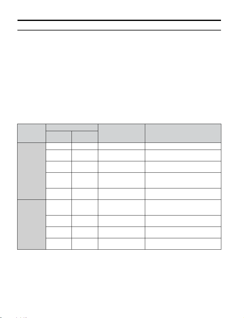
Table 5 Ground Wire Selection
Ground Wire
Length
(mm/in)
150/5.9
200/7.9
250/9.8 –
400/15.7 –
For IP20/Open-Chassis models, go to Step 9. on page 36.
5.
For IP20/NEMA Type 1 enclosure models CIMR-VooAooooF, loosen the screw
6.
on the front of the NEMA Type 1 terminal cover and remove it from the drive. Refer
to Figure 8 for details.
Single-Phase
200 V Class
BA0001
BA0002
BA0003
BA0006
BA0010
BA0012
BA0018
Drive Model
Three-Phase
200 V Class
2A0001
2A0002
2A0004
2A0006
2A0010
2A0012
2A0020
2A0030
2A0040
2A0056
2A0069
Three-Phase
400 V Class
4A0001
4A0002
4A0004
4A0005
4A0007
4A0009
4A0011
4A0018
4A0023
4A0031
4A0038
–
20
YASKAWA TOEP YAICOM 17A V1000 Option Dual-Port Modbus TCP/IP SI-EM3D/V Installation Manual
Page 21

5 Installation Procedure
Refer to Figure 9 for drive models BA0006F to BA0018F, 2A0010F to 2A0069F, and
4A0001F to 4A0038F, which require removing the plastic terminal cover prior to
removing the NEMA Type 1 terminal cover.
Note: Installing the option on an IP20/NEMA Type 1 enclosure drive voids NEMA Type 1 protection
while maintaining IP20 conformity.
Figure 8 Remove the NEMA Type 1 Terminal Cover
(Models BA0001F to BA0003F and 2A0001F to 2A0006F)
Figure 9 Remove the Terminal Cover on an IP20/NEMA Type 1 Drive
(Models BA0006F to BA0018F; 2A0008F to 2A0069F; 4A0001F to 4A0038F)
For models BA0001F to BA0003F and 2A0001F to 2A0006F, loosen the screws
7.
attaching the NEMA Type 1 conduit bracket to the drive to remove the NEMA Type
1 conduit bracket.
YASKAWA TOEP YAICOM 17A V1000 Option Dual-Port Modbus TCP/IP SI-EM3D/V Installation Manual
21
Page 22

Ground terminal
Ground wire
Drive ground terminal/
NEMA Type 1 conduit
bracket screw
Ground wire
Drive-side
connector
Screw size:
M3.5 to M6
Option unit
connector
Screw size: M3
5 Installation Procedure
Figure 10 Remove the NEMA Type 1 Conduit Bracket
(Models BA0001F to BA0003F and 2A0001F to 2A0006F)
On models (BA0001F to BA0003F and 2A0001F to 2A0006F), the screw for the drive
8.
ground terminal also acts as one of the screws that attaches the NEMA Type 1 conduit
bracket to the drive. Reattach the NEMA Type 1 conduit bracket according to Figure
27 and connect the drive-side of the ground wire to the drive ground terminal.
Note: The different ground wires packaged with the option connect the option to different drive
models. Select the proper ground wire depending on drive size. Refer to Table 5 on page 20
for ground wire selection by drive model.
Figure 11 Reattach the NEMA Type 1 Conduit Bracket and Connect the Ground Wire
22
(Models BA0001F to BA0003F and 2A0001F to 2A0006F)
YASKAWA TOEP YAICOM 17A V1000 Option Dual-Port Modbus TCP/IP SI-EM3D/V Installation Manual
Page 23

IP20/Open-Chassis IP20/NEMA Type 1 Enclosure
5 Installation Procedure
Reattach the bottom cover. Keep the ground wire inside of the bottom cover when
9.
reattaching.
Figure 12 Reattach the Bottom Cover
On models BA0006 to BA0018, 2A0008 to 2A0069, and 4A0001 to 4A0038, reattach
10.
the terminal cover.
Refer to Figure 13 and Figure 14 for drive models BA0006 to BA0018, 2A0008 to
2A0020, and 4A0001 to 4A0011, which require routing the ground wire through the
provided notch when reinstalling the terminal cover.
YASKAWA TOEP YAICOM 17A V1000 Option Dual-Port Modbus TCP/IP SI-EM3D/V Installation Manual
23
Page 24

Ground wire
routing notch
5 Installation Procedure
(Models BA0006 to BA0018; 2A0008 to 2A0069; 4A0001 to 4A0038)
(Models BA0006 to BA0018; 2A0008 to 2A0020; 4A0001 to 4A0011)
Remove the option cover and pass the ground wire through the inside of the drive
11.
Figure 13 Reattach the Terminal Cover
Figure 14 Terminal Cover Ground Wire Notch
bottom cover and into the through-hole for the ground wire at the front of the option.
24
YASKAWA TOEP YAICOM 17A V1000 Option Dual-Port Modbus TCP/IP SI-EM3D/V Installation Manual
Page 25

Line up tabs
Line up tabs
5 Installation Procedure
Figure 15 Ground Wire Routing
Attach the option to the drive. Properly seat the tabs on the left and right sides of the
12.
option to the drive case.
Connect the ground wire at the option ground terminal. Tighten the screw to 0.5 to
13.
0.6 N•m or (4.4 to 5.3 in lbs) using an M3 Phillips screwdriver.
YASKAWA TOEP YAICOM 17A V1000 Option Dual-Port Modbus TCP/IP SI-EM3D/V Installation Manual
Figure 16 Connect the Option
25
Page 26

Option ground terminal
5 Installation Procedure
Figure 17 Connect the Ground Wire to the Option
Connect the communication cable to the option modular connector (CN1) port 1.
14.
To connect the option to a network, firmly connect RJ45 8-pin shielded twisted pair
Cat5e cable(s) into the modular connector ports (see Figure 18).
Communication Cable Specifications
Only use cable recommended for Modbus TCP/IP. Using a cable not specifically
recommended may cause the option or drive to malfunction.
The dual RJ45 network ports on the option board act as a switch to allow for flexibility
in cabling topology. For example, a traditional star network topology may be employed
by using a single port on the option board. Alternatively, a daisy-chained approach
may be employed by using both RJ45 ports. The daisy-chained approach reduces
the requirements of central switch ports. A ring topology is also possible. When
implementing a ring topology, Rapid Spanning Tree Protocol (RSTP) must be enabled
to function correctly.
26
YASKAWA TOEP YAICOM 17A V1000 Option Dual-Port Modbus TCP/IP SI-EM3D/V Installation Manual
Page 27

Figure 18 Communication Cable Ports
STOP
(Hz)
(Hz)
(A)
(V)
V1000
STOP
(Hz)
(Hz)
(A)
(V)
V1000
STOP
(Hz)
(Hz)
(A)
(V)
V1000
STOP
(Hz)
(Hz)
(A)
(V)
V1000
STOP
(Hz)
(Hz)
(A)
(V)
V1000
STOP
(Hz)
(Hz)
(A)
(V)
V1000
STOP
(Hz)
(Hz)
(A)
(V)
V1000
STOP
(Hz)
(Hz)
(A)
(V)
V1000
STOP
(Hz)
(Hz)
(A)
(V)
V1000
Star Topology
Daisy-Chained Topology
Ring Topology
5 Installation Procedure
YASKAWA TOEP YAICOM 17A V1000 Option Dual-Port Modbus TCP/IP SI-EM3D/V Installation Manual
Figure 19 Topology Options
27
Page 28

V1000
M
U/T1
V/T2
W/T3
R/L1
S/L2
T/L3
SI-EM3D/V
Modbus TCP/IP
Option
FE
<1>
Modbus
TCP/IP Cable
MotorPower
Modbus
TCP/IP Cable
5 Installation Procedure
Use the second communication cable port to daisy chain a series of drives where
15.
applicable.
Attach the option cover by aligning the tabs with the mounting holes, seat the front
16.
cover into place, and tighten the screw on the front.
Figure 20 Option Connection Diagram
28
YASKAWA TOEP YAICOM 17A V1000 Option Dual-Port Modbus TCP/IP SI-EM3D/V Installation Manual
Page 29

Line up tabs
Figure 21 Attach the Option Cover
5 Installation Procedure
Note: Take proper precautions when wiring the option so that the front covers will easily fit back onto
YASKAWA TOEP YAICOM 17A V1000 Option Dual-Port Modbus TCP/IP SI-EM3D/V Installation Manual
the drive. Make sure no cables are pinched between the front covers and the drive when
replacing the covers.
Set drive parameters in Table 6 for proper option performance.
17.
29
Page 30

6 Related Drive Parameters
6 Related Drive Parameters
The following parameters are used to set up the drive for operation with the option. Parameter
setting instructions can be found in the drive manual.
Confirm proper setting of the parameters in Table 6 before starting network communications.
After changing parameter settings, cycle power to the drive for the new settings to take effect.
Table 6 Related Parameters
No.
(Addr.
Hex)
b1-01
(0180)
<1>
b1-02
(0181)
<1>
F6-01
(03A2)
F6-02
(03A3)
F6-03
(03A4)
F6-07
(03A8)
F6-08
(036A)
<4>
F6-14
(03BB)
Name Description Values
0: Digital operator
Frequency Reference
Selection 1
Run Command
Selection 1
Communications Error
Operation Selection
External Fault from
Comm. Option
Detection Selection
External Fault from
Comm. Option
Operation Selection
Multi-Step Speed
Enable/Disable
Selection when NefRef/
ComRef is Selected
Reset Communication
Parameters
bUS Error Auto Reset
1: Analog input terminals
2: MEMOBUS/Modbus communications
3: Option PCB
4: Pulse input (terminal RP)
0: Digital operator
1: Digital input terminals
2: MEMOBUS/Modbus communications
3: Option PCB
0: Ramp to stop. Decelerate to stop using the deceleration
time in C1-02.
1: Coast to stop
2: Fast Stop. Decelerate to stop using the deceleration time
in C1-09.
3: Alarm only
4: Alarm (d1-04)
5: Alarm Ramp to Stop
1: Detection during run only
0: Ramp to stop. Decelerate to stop using the deceleration
time in C1-02.
1: Coast to stop
2: Fast Stop. Decelerate to stop using the deceleration time
in C1-09.
3: Alarm only
0: Multi-step reference disabled (same as F7)
1: Multi-step reference enabled (same as V7)
0: Communication-related parameters (F6-oo/F7-oo)
are not reset when the drive is initialized using A1-03.
1: Reset all communication-related parameters
(F6-oo/F7-oo) when the drive is initialized using
A1-03.
0: Disabled
1: Enabled
<2>
<3>
<3>
<2>
Default: 1
Range: 0 to 4
Default: 1
Range: 0 to 3
Default: 1
Range: 0 to 5
Default: 0
Range: 0, 1
Default: 1
Range: 0 to 3
Default: 1
Range: 0, 1
Default: 0
Range: 0, 1
Default: 0
Range: 0, 1
30
YASKAWA TOEP YAICOM 17A V1000 Option Dual-Port Modbus TCP/IP SI-EM3D/V Installation Manual
Page 31

No.
(Addr.
Hex)
F7-01
(03E5)
<5>
F7-02
(03E6)
<5>
F7-03
(03E7)
<5>
F7-04
(03E8)
<5>
F7-05
(03E9)
F7-06
(03EA)
F7-07
(03EB)
F7-08
(03EC)
F7-09
(03ED)
F7-10
(03EE)
F7-11
(03EF)
F7-12
(03E0)
F7-13
(03F1)
F7-14
(03F2)
Name Description Values
IP Address 1 Sets the most significant octet of network static IP address.
IP Address 2
IP Address 3
IP Address 4
Subnet Mask 1
Subnet Mask 2
Subnet Mask 3
Subnet Mask 4
Gateway Address 1 Sets the most significant octet of network Gateway address.
Gateway Address 2
Gateway Address 3
Gateway Address 4
Address Mode at
Startup
Duplex Mode Selection
Sets the second most significant octet of network static IP
address.
Sets the third most significant octet of network static IP
address.
Sets the fourth most significant octet of network static IP
address.
Sets the most significant octet of network static Subnet
Mask.
Sets the second most significant octet of network static
Subnet Mask.
Sets the third most significant octet of network static Subnet
Mask.
Sets the fourth most significant octet of network static
Subnet Mask.
Sets the second most significant octet of network Gateway
address.
Sets the third most significant octet of network Gateway
address.
Sets the fourth most significant octet of network Gateway
address.
Select the option address setting method
<6>
0: Static
1: BOOTP
2: DHCP
Selects duplex mode setting.
0: Half duplex forced (both ports)
1: Auto-negotiate duplex mode and communication speed
(both ports)
2: Full duplex forced (both ports)
3: Half (port 1)/Auto (port 2)
4: Half (Port 1)/Full (port 2)
5: Auto (port 1)/Half (port 2)
6: Auto (port 1)/Full (port 2)
7: Full (port 1)/Half (port 2)
8: Full (port 1)/Auto (port 2)
<7>
<7>
6 Related Drive Parameters
Default: 192
Range: 0 to 255
Default: 168
Range: 0 to 255
Default: 1
Range: 0 to 255
Default: 20
Range: 0 to 255
Default: 255
Range: 0 to 255
Default: 255
Range: 0 to 255
Default: 255
Range: 0 to 255
Default: 0
Range: 0 to 255
Default: 192
Range: 0 to 255
Default: 168
Range: 0 to 255
Default: 1
Range: 0 to 255
Default: 1
Range: 0 to 255
Default: 2
Range: 0 to 2
<8>
Default:
Range: 0 to 8
<9>
YASKAWA TOEP YAICOM 17A V1000 Option Dual-Port Modbus TCP/IP SI-EM3D/V Installation Manual
31
Page 32

6 Related Drive Parameters
No.
(Addr.
Hex)
F7-15
(03F3)
F7-16
(03F4)
H5-11
(043C)
<1> To start and stop the drive with the master device using serial communications, set b1-02 to 3. To control the
drive frequency reference of the drive via the master device, set b1-01 to 3.
<2> When set to 3, 4, or 5, the drive will continue to operate when a fault is detected. Take safety measures, such as
installing an emergency stop switch.
<3> Available in drive software versions PRG: 1024 and later.
<4> Parameter setting value is not reset to the default value when the drive is initialized.
<5> Cycle power for setting changes to take effect.
<6> When F7-13 is set to 0, parameters F7-01 to F7-12 must be set, and all IP Addresses (as defined with parameters
F7-01 to F7-04) must be unique.
<7> When F7-14 is set to 0 or 2, parameter F7-15 must be set.
<8> Default setting differs depending on drive software version. PRG: 1012 to 1015: 0
PRG: 1016 and later: 1
<9> Setting range differs depending on drive software version. PRG: 1012 to 1023, Range: 0 to 2
PRG: 1024 and later, Range: 0 to 8
<10> Setting values differ depending on drive software version. PRG: 1012 to 1015, Default: 0; Range: 0, 10, 100
PRG: 1016 to 1023, Default: 10; Range: 10, 100
PRG: 1024 and later, Default: 10; Range: 10; 100 to 102
No. Name Description Value Range
U6-80
to
Online IP Address
U6-83
U6-84
to
Online Subnet Subnet currently available; U6-84 is the most significant octet 0 to 255
U6-87
Name Description Values
Sets the communication speed
Communication Speed
Selection
Communication Loss
Timeout
Communications
ENTER Function
Selection
0: 10 Mbps
10: 10 Mbps
100: 100 Mbps
101: 10 (Port 1)/100 Mbps (port 2)
102: 100 (Port 1)/10 Mbps (port 2)
Sets the timeout value for communication loss detection in
tenths of a second. A value of 0 disables the connection
timeout.
Example: An entered value of 100 represents 10.0 seconds.
Selects the function for the ENTER command that saves
parameter data to the drive.
0: Parameter changes are activated when ENTER command
is written
1: Parameter changes are activated immediately without use
of ENTER command
Table 7 Option Monitors
IP Address currently available; U6-80 is the most significant
octet
Default: 10
Range: 10; 100 to
102
Default: 0.0
Min.: 0.0
Max.: 30.0
Default: 1
Range: 0, 1
0 to 255
<10>
<10>
32
YASKAWA TOEP YAICOM 17A V1000 Option Dual-Port Modbus TCP/IP SI-EM3D/V Installation Manual
Page 33

6 Related Drive Parameters
No. Name Description Value Range
U6-88
to
Online Gateway
U6-91
U6-92 Online Speed Link Speed
U6-93 Online Duplex Duplex Setting 0: Half, 1: Full
U6-94 Port 2 Speed Port 2 Link Speed 0: Half, 1: Full
U6-95 Port 2 Duplex Port 2 Duplex Setting
U6-96 RSTP RSTP Role and State 0000 to 9292
U6-98 First Fault First Option Fault –
U6-99 Current Fault Current Option Fault –
Gateway currently available; U6-88 is the most significant
octet
0 to 255
10: 10 Mbps
100: 100 Mbps
10: 10 Mbps
100: 100 Mbps
YASKAWA TOEP YAICOM 17A V1000 Option Dual-Port Modbus TCP/IP SI-EM3D/V Installation Manual
33
Page 34

7 Modbus TCP/IP Messaging
7 Modbus TCP/IP Messaging
u
Modbus TCP/IP Overview
The Modbus TCP/IP protocol is essentially the Modbus protocol over an Modbus TCP/IP
network. A master controller (typically a PLC) sends commands to slave devices, which then
perform the specified functions and send a response to the master. The drive using the option
has slave functionality.
Supported Modbus TCP/IP Commands
n
Table 8 Supported Modbus TCP/IP Commands
Function Code Function Name
03H Read Multiple Registers
06H Write Single Register
10H Write Multiple Registers
17H Read/Write Multiple Registers
Drive Modbus TCP/IP Option Registers
n
All of the command registers, monitor registers, and parameters documented in the drive
Technical Manual are accessible via the option.
High Speed Access Drive Modbus TCP/IP Option Registers
n
Many of the registers required for control have been specially mapped to provide higher speed
access to increase network performance. Use these registers for the best response times.
All of the drive command registers have been mapped to this high speed access area (Modbus
TCP/IP registers 01H to 01FH). In addition, the monitors shown in Table 9 are mapped for
high speed access.
34
YASKAWA TOEP YAICOM 17A V1000 Option Dual-Port Modbus TCP/IP SI-EM3D/V Installation Manual
Page 35

7 Modbus TCP/IP Messaging
Table 9 Drive Registers
Drive
Addre
Regist
ss
(hex)
2000 4B
2001 44 Motor Speed Monitor (U1-05)
2002 48 Torque Reference Monitor (U1-09)
2003 F0 PG Count Channel 1
2004 40 Frequency Reference Monitor (U1-01)
2005 41 Output Frequency Monitor (U1-02)
2006 26
2007 4F Terminal A2 Input Level Monitor (U1-14)
2008 46 DC Bus Voltage Monitor (U1-07)
er
(hex)
Description Bit Description
0 During Run
1 During Zero Speed
2 During Reverse Direction
3 During Fault Reset Signal Input
4 During Speed Agree
5 Drive Ready
6 Alarm
Status Word
(U1-12)
7 Fault
8 During Operation Error (oPEoo)
9 During Momentary Power Loss
A Motor 2 Selected
B Reserved
C Reserved
D Reserved
E ComRef Status, NetRef Status
F ComCtrl Status, NetCtrl Status
Output Current (U1-03)
0.1 A
YASKAWA TOEP YAICOM 17A V1000 Option Dual-Port Modbus TCP/IP SI-EM3D/V Installation Manual
35
Page 36

7 Modbus TCP/IP Messaging
Drive
Addre
Regist
ss
(hex)
2009 C0 Error Signal 1
er
(hex)
Description Bit Description
0 Reserved
1 Undervoltage (Uv1)
2 Control Power Supply Undervoltage (Uv2)
3 Soft Charge Circuit Fault (Uv3)
4 Reserved
5 Ground Fault (GF)
6 Overcurrent (oC)
7 Overvoltage (ov)
8 Heatsink Overheat (oH)
9 Heatsink Overheat (oH1)
A Motor Overload (oL1)
B Drive Overload (oL2)
C Overtorque Detection 1 (oL3)
D Overtorque Detection 2 (oL4)
E Dynamic Braking Transistor Fault (rr)
F Braking Resister Overheat (rH)
36
YASKAWA TOEP YAICOM 17A V1000 Option Dual-Port Modbus TCP/IP SI-EM3D/V Installation Manual
Page 37

Drive
Addre
Regist
ss
(hex)
200A C1 Error Signal 2
er
(hex)
Description Bit Description
7 Modbus TCP/IP Messaging
0 External Fault at input terminal S3 (EF3)
1 External Fault at input terminal S4 (EF4)
2 External Fault at input terminal S5 (EF5)
3 External Fault at input terminal S6 (EF6)
4 External Fault at input terminal S7 (EF7)
5 External Fault at input terminal S8 (EF8)
6 Cooling fan Error (FAn)
5 Reserved
6 Reserved
7 Overspeed (os)
8 Excessive Speed Deviation (dEv)
9 PG Disconnected (PGo)
A Input Phase Loss (PF)
B Output Phase Loss (LF)
C Motor Overheat (PTC input) (oH3)
D Digital Operator Connection Fault (oPr)
E EEPROM Write Error (Err)
F Motor Overheat Fault (PTC input) (oH4)
YASKAWA TOEP YAICOM 17A V1000 Option Dual-Port Modbus TCP/IP SI-EM3D/V Installation Manual
37
Page 38

7 Modbus TCP/IP Messaging
Drive
Addre
Regist
ss
(hex)
200B C2 Error Signal 3
200C 4E Terminal A1 Input Level Monitor (U1-13)
200D 49 Digital Input Terminal Status (U1-10)
200E 50 Terminal A3 Input Level Monitor (U1-15)
200F F1 PG Count Channel 2
2010 4D Drive Software Number (Flash) (U1-25)
er
(hex)
Description Bit Description
0 MEMOBUS/Modbus Communication Error (CE)
1 Option Communication Error (bUS)
2 Reserved
3 Reserved
4 Control Fault (CF)
5 Zero Servo Fault (SvE)
5 Reserved
6 Option External Fault (EF0)
7 PID Feedback Loss (FbL)
8 Undertorque Detection 1 (UL3)
9 UL4 Undertorque Detection 2 (UL4)
A High Slip Braking Overload (oL7)
B Reserved
C Reserved
D Reserved
E Reserved
F Hardware Fault (includes oFo)
u
Enter Command Types
The drive supports two types of Enter commands as shown in Table 10. An Enter command
is enabled by writing 0 to register number 0900H or 0910H. These registers can be written to
only. An error will occur if the user attempts to read from these registers.
38
YASKAWA TOEP YAICOM 17A V1000 Option Dual-Port Modbus TCP/IP SI-EM3D/V Installation Manual
Page 39

7 Modbus TCP/IP Messaging
Table 10 Enter Command Types
Register No. Description
0900H
0910H Writes data in the RAM only. Parameter changes are lost when the drive is shut off.
Note: 1. Because the EEPROM can be written to a maximum of 100,000 times, refrain from writing to the
u
Enter Command Settings when Upgrading the Drive
Writes data into the EEPROM (non-volatile memory) of the drive and enables the data in RAM at
the same time. Parameter changes remain even if the power supply is cycled.
EEPROM too often. The Enter command registers are write-only. Consequently, if these registers
are read, then the register address will be invalid (Error code: 02H). An Enter command is not required
if reference or broadcast data are sent to the drive.
2. Parameter data cannot be written to EEPROM during undervoltage, even using 0900H.
3. If undervoltage occurs when a making several parameter changes issued with a single ENTER
command, the writing process may be aborted before all of the new changes have been written.
Because all of the data has not yet been written, the EEPROM data error “CPF06” will be displayed
the next time power to the drive is cycled. To prevent this problem, wait approximately 5 seconds
after issuing the ENTER command before shutting off drive power.
When replacing earlier Yaskawa drive models with a V1000 and keeping the MEMOBUS/
Modbus communications settings, parameter H5-11 needs to be set in accordance with how
the Enter command functions in the older drive. H5-11 determines if an Enter command is
needed to activate parameter changes in the drive.
• Set parameter H5-11 to 0 when upgrading from a G7 or F7 series drive to V1000-Series
drive.
• Set parameter H5-11 to 1 when upgrading from a V7 series drive to V1000-Series drive.
H5-11 and the Enter Command
n
H5-11 Settings H5-11 = 0 H5-11 = 1
Drive being replaced G7, F7 V7
How parameter settings
are enabled
Upper/lower limit check
Default value of related
parameters
Error handling when
setting multiple
parameters
When the Enter command is received from
the master.
Upper/lower limit check is performed taking
the settings of related parameters into
account.
Not affected. The settings of related
parameters remain unchanged. They must
be changed manually if needed.
Data is accepted even if one setting is
invalid. The invalid setting will be
discarded. No error message occurs.
As soon as the value is changed.
The upper/lower limit of the changed
parameter is checked only.
The default settings of related parameters
are changed automatically.
Error occurs if only one setting is invalid.
All data sent are discarded.
YASKAWA TOEP YAICOM 17A V1000 Option Dual-Port Modbus TCP/IP SI-EM3D/V Installation Manual
39
Page 40

8 Web Interface
8 Web Interface
The option contains a series of web pages that allow for viewing of status and diagnostic
information through a standard web browser.
The web page is accessed through a self-contained web server at port 80. Access the home
page by typing the IP address of the option in a web browser. Example: "http://192.168.1.20"
The IP address of the option can be read using monitors U6-80 to U6-83 on the digital operator
if it is unknown. Refer to Option Monitors on page 32 for details.
The home page is an HTML-based page providing basic drive and option data and a link to
an enhanced web page requiring a Java© enabled web browser.
Enhanced Web Page Notes:
• The Enhanced Web Pages use a series of Java© applets.
• PCs must have Java SE 6 Update 14 or later installed to view the enhanced web pages.
• The Java© applets require an internet connection to check the revocation status.
• When no internet connection is available, disable the revocation check by changing a Java
setting in the PC: All Programs / Java / Configure Java / Advanced Tab. Set "Perform
certificate checks on" to "Do not check".
Enhanced Web Page Tab Page
Main Tab 43
Drive Status Tab 44
Network Tab Refer to the option Technical Manual for details on this tab.
Email Alerts Tab Refer to the option Technical Manual for details on this tab.
Parameter Access Tab
Configuration Tab
Custom Tab 45
<1> Accessible after entering a valid password.
<1>
<1>
Refer to the option Technical Manual for details on this tab.
Refer to the option Technical Manual for details on this tab.
40
YASKAWA TOEP YAICOM 17A V1000 Option Dual-Port Modbus TCP/IP SI-EM3D/V Installation Manual
Page 41
8 Web Interface
u
HTML Home Page
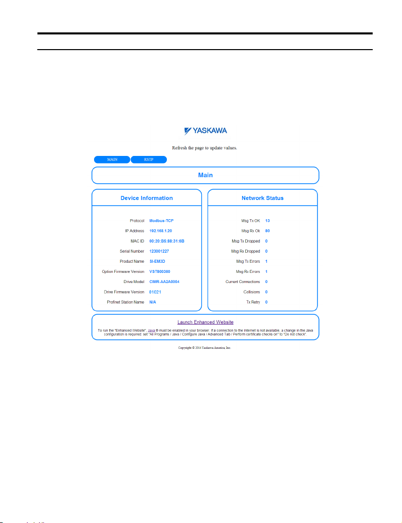
The main HTML home page provides basic drive and option data and a link to an enhanced
web page. The RSTP enabled home page provides Rapid Spanning Tree Protocol data.
Missing ID# section_Rapid_Spanning_Tree_Protocol1098742473 for details on RSTP.
Main HTML Home Page
n
Figure 22 Main HTML Home Page
YASKAWA TOEP YAICOM 17A V1000 Option Dual-Port Modbus TCP/IP SI-EM3D/V Installation Manual
41
Page 42

8 Web Interface
RSTP Enabled HTML Home Page
n
Figure 23 RSTP Enabled HTML Home Page
42
YASKAWA TOEP YAICOM 17A V1000 Option Dual-Port Modbus TCP/IP SI-EM3D/V Installation Manual
Page 43

8 Web Interface
u
Main Tab
The Main tab shows basic option information such as IP address, MAC address, and firmware
version.
Figure 24 Main Tab View
YASKAWA TOEP YAICOM 17A V1000 Option Dual-Port Modbus TCP/IP SI-EM3D/V Installation Manual
43
Page 44

8 Web Interface
u
Drive Status Tab
The Drive Status tab shows basic I/O information and drive state information.
Figure 25 Drive Status Tab View
44
YASKAWA TOEP YAICOM 17A V1000 Option Dual-Port Modbus TCP/IP SI-EM3D/V Installation Manual
Page 45

u
Custom Tab
The Custom tab displays a selection of quick setting parameters.
8 Web Interface
Figure 26 Custom Tab View
YASKAWA TOEP YAICOM 17A V1000 Option Dual-Port Modbus TCP/IP SI-EM3D/V Installation Manual
45
Page 46

9 Rapid Spanning Tree Protocol
9 Rapid Spanning Tree Protocol
Rapid Spanning Tree Protocol (RSTP) is a mechanism that allows an Ethernet network to be
configured as a ring or other topology that may have more than one pathway to each node.
The RSTP protocol automatically determines the most efficient pathway to each node and
disables any redundant pathways.
Refer to the option Technical Manual for a full description of RSTP features and functions.
46
YASKAWA TOEP YAICOM 17A V1000 Option Dual-Port Modbus TCP/IP SI-EM3D/V Installation Manual
Page 47

10 Troubleshooting
10 Troubleshooting
u
Drive-Side Error Codes
Drive-side error codes appear on the drive digital operator. Causes of the errors and corrective
actions are listed below. Refer to the drive manual for additional error codes that may appear
on the drive digital operator.
Faults
n
Both bUS (Option Communication Error) and EF0 (Option Card External Fault) can appear
as an alarm or as a fault. When a fault occurs, the digital operator ALM LED remains lit.
When an alarm occurs, the ALM LED flashes.
If communication stops while the drive is running, use the following questions as a guide to
help remedy the fault:
• Is the option properly installed?
• Are the communication lines properly connected to the option? Are the wires loose?
• Is the controller program working? Has the controller/PLC CPU stopped?
• Did a momentary power loss interrupt communications?
Digital Operator Display Fault Name
Option Communication Error
bUS
Cause Possible Solution
Master controller (PLC) has
stopped communicating
Communication cable is not
connected properly
A data error occurred due to noise
Option is damaged
• The connection was lost after establishing initial communication.
• Only detected when the Run command or frequency reference is assigned to
the option (b1-01 = 3 or b1-02 = 3).
• Check that power is supplied to the PLC
• Check that PLC is not in program mode
• Check for faulty wiring
• Correct any wiring problems
• Check the various options available to minimize the effects of noise
• Counteract noise in the control circuit, main circuit, and ground wiring
• If a magnetic contactor is identified as a source of noise, install a surge absorber
to the contactor coil
• Make sure the cable used meets requirements
• Make sure the option ground wire is connected between option FE terminal
and the drive ground terminal connected to earth ground
If there are no problems with the wiring and the error continues to occur, replace
the option.
YASKAWA TOEP YAICOM 17A V1000 Option Dual-Port Modbus TCP/IP SI-EM3D/V Installation Manual
47
Page 48
10 Troubleshooting
Digital Operator Display Fault Name
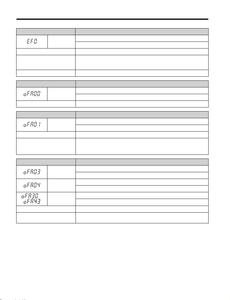
EF0
Cause Possible Solutions
An external fault was received from
the PLC and F6-03 is set to a value
other than 3.
Problem with the PLC program Check the PLC program and correct problems.
Digital Operator Display Fault Name
oFA00
Cause Possible Solution
Digital Operator Display Fault Name
oFA01
Cause Possible Solution
The option card connection is
faulty
Digital Operator Display Fault Name
oFA03
oFA04
to
oFA30 to
oFA43
Cause Possible Solution
Option card or hardware is
damaged.
Option Card External Fault
The alarm function for an external device has been triggered.
• Remove the cause of the external fault.
• Remove the external fault input from the PLC.
Option Card Connection Error at Option Port CN5-A
The option card is incompatible with the drive.
Option Card Fault
Option not properly connected
• Turn off the power and reconnect the option card.
• Check if the option card is properly plugged into the option port. Make sure
the card is fixed properly.
Option Card Fault (port A)
Option card self-diagnostic error
Option Card Fault (port A)
An error occurred attempting to write to the option card memory.
Option Card Fault (port A)
Communication ID error
Replace the option card. Contact Yaskawa for consultation.
48
YASKAWA TOEP YAICOM 17A V1000 Option Dual-Port Modbus TCP/IP SI-EM3D/V Installation Manual
Page 49

10 Troubleshooting
Minor Faults and Alarms
n
Digital Operator Display Minor Fault Name
CALL
Cause Possible Solutions
Communications wiring is faulty,
there is a short circuit, the wiring
is incorrect, or the connections are
poor.
Programming error on the master
side.
Communications circuitry is
damaged.
bUS Fault Tolerance
n
Serial Communication Transmission Error
Communication has not yet been established.
• Check for wiring errors.
• Correct the wiring.
• Check for disconnected cables and short circuits. Repair as
needed.
Check communications at start-up and correct programming
errors.
• Perform a self-diagnostics check.
• If the problem continues, replace the control board or the
entire drive. Contact Yaskawa for instructions on replacing
the control board.
Minor Fault
(H2-oo = 10)
YES
bUS Fault Auto-Restart
Parameter F6-14, bUS Fault Auto Reset Select, will appear when the option is installed.
Setting F6-14 = 0 (Disabled) or F6-01 = 3 or greater (Alarm only) will not affect standard
default drive behavior.
Setting F6-14 = 1 (Enabled) AND F6-01 < 3 (Fault) will cause the following operation: The
bUS fault occurs after the F7-16 delay and the Run command is removed from the drive. Then
the option throws a bUS fault to the drive. When the condition is removed, the option
commands a fault reset and returns control of the drive to the Modbus TCP/IP network.
Note: The option will only read parameter F6-01 and F6-14 from the drive during power-up.
bUS Fault Delay
Parameter F7-16, Communications Loss Detection Time Delay, will appear when the option
is installed.
The setting value of F7-16 is the length of time that the option will delay sending the bUS
fault to the drive.
The status LEDs on the option are not affected by the delay time set in F7-16; the LEDs will
indicate the bUS condition immediately.
Note: The option will only read parameter F7-16 from the drive during power-up.
YASKAWA TOEP YAICOM 17A V1000 Option Dual-Port Modbus TCP/IP SI-EM3D/V Installation Manual
49
Page 50

10 Troubleshooting
u
Option Error Codes
Option Fault Monitors U6-98 and U6-99
n
The option can declare error/warning conditions via drive monitor parameters on the drive
digital operator as shown in Table 11.
Table 11 Option Fault Monitor Descriptions
Fault
Condition
No Fault n/a 0 No faults
Force Fault EF0 3
Connection
Timeout
Duplicate IP
Address
Default MAC
Address
Network Link
Down
Hardware Error BUS ERROR 1105
Fault Declared
BUS ERROR 1101 The control connection timed out.
BUS ERROR 1102
None 1103
BUS ERROR 1104 No network link to option.
Status Value
(U6-98/U6-99)
Description
Network sent a message to force this node
to the fault state.
This node and at least one other node have
the same IP Address.
Factory default MAC Address
programmed into the option. Return for
reprogramming.
Option card hardware has stopped
functioning. Cycle power to the drive.
Two drive monitor parameters, U6-98 and U6-99 assist the user in network troubleshooting.
• U6-98 displays the first declared fault since the last power cycle. U6-98 is only cleared
upon drive power-up.
• U6-99 displays the present option status. U6-99 is cleared upon a network-issued fault reset
and upon power-up.
If another fault occurs while the original fault is still active, parameter U6-98 retains the
original fault value and U6-99 stores the new fault status value.
50
YASKAWA TOEP YAICOM 17A V1000 Option Dual-Port Modbus TCP/IP SI-EM3D/V Installation Manual
Page 51

11 Specifications
11 Specifications
Table 12 Option Specifications
Item Specification
Model SI-EM3D/V
• Read Multiple Registers (03H)
• Write Single Register (06H)
Supported Messages
Option Conformance Modbus-IDA Passed
Connector Type RJ45 8-pin Shielded Twisted Pair Cat5e cable
Physical Layer Type Isolated Physical Layer
IP Address Setting Programmable from drive keypad or network
Communication Speed
Number of Connections
Duplex Mode Half-forced, Auto-negotiate, Full-forced
Address Startup Mode Static, BOOTP, DHCP
Ambient Temperature -10 °C to +50 °C (14 °F to 122 °F)
Humidity 95% RH or lower with no condensation
Storage Temperature -20 °C to +60 °C (-4 °F to +140 °F) allowed for short-term transport of the product
Area of Use Indoor (free of corrosive gas, airborne particles, etc.)
Altitude 1000 m (3280 ft.) or lower
• Write Multiple Registers (10H)
• Read and Write Registers (17H)
Commands that support multiple registers have a maximum Read and Write size
of 16 registers.
Programmable from drive keypad or network:
10/100 Mbps, auto-negotiate
Modbus TCP/IP: 10
Web Page Access: 2
YASKAWA TOEP YAICOM 17A V1000 Option Dual-Port Modbus TCP/IP SI-EM3D/V Installation Manual
51
Page 52

11 Specifications
This Page Intentionally Blank
52
YASKAWA TOEP YAICOM 17A V1000 Option Dual-Port Modbus TCP/IP SI-EM3D/V Installation Manual
Page 53

This Page Intentionally Blank
YASKAWA TOEP YAICOM 17A V1000 Option Dual-Port Modbus TCP/IP SI-EM3D/V Installation Manual
53
Page 54

Revision History
MANUAL NO.
Example:
TOEP YAICOM 17A
Published in USA July 2014 14-7
Date of publication
Date of original publication
The revision dates and the numbers of the revised manuals appear on the bottom of the back cover.
Date of Publication
July 2014 - - First Edition
Revision
Number
Section Revised Content
54
YASKAWA TOEP YAICOM 17A V1000 Option Dual-Port Modbus TCP/IP SI-EM3D/V Installation Manual
Page 55

Page 56

YASKAWA AC Drive V1000 Option
Modbus TCP/IP
Installation Manual
YASKAWA AMERICA, INC.
2121 Norman Drive South, Waukegan, IL 60085, U.S.A.
Phone: (800) YASKAWA (927-5292) or 1-847-887-7000 Fax: 1-847-887-7310
http://www.yaskawa.com
YASKAWA ELÉTRICO DO BRASIL LTDA.
Avenda Fagundes Filho, 620 Bairro Saude, São Paulo, SP04304-000, Brasil
Phone: 55-11-3585-1100
http://www.yaskawa.com.br
Fax: 55-11-5581-8795
TM
YASKAWA AMERICA, INC.
In th e event that t he end user of this product i s to be the mi litary and sai d produ ct is t o ploye d in an y weapons system s or th e manuf acture
there of, the export will f all und er the relevant regulatio ns as s tipulat ed in t he Foreig n ge and Foreign Trade Reg ulation s. The refore , be
sure to foll ow all procedures an d submi t all rele vant docum entati on accordi ng to any a r ules, reg ulation s and l aws tha t ma y apply .
ions are subje ct to change wi thout n otice f or ongoing produc t modif ication s prove ments.
Speci ficat
© 2014 YASKAWA AMER ICA, IN C. All rights reserved.
be e m
Excha n
nd al l
and i m
MANUAL NO. TOEP YAICOM 17A
Published in U.S.A. July 2014 14-7
 Loading...