

Ratings and Specifications
Time Rating: Continuous
Vibration Class: V15
Insulation Resistance: 500 VDC, 10 M
Ambient Temperature: 0 to 40˚C
Excitation: Permanent magnet
Mounting: Flange-mounted
Thermal Class: B
Ω min.
Withstand Voltage: 1500 VAC for one minute
Enclosure: Totally enclosed, self-cooled, IP65
(except for shaft opening)
Ambient Humidity: 20% to 80% (no condensation)
Drive Method: Direct drive
Rotation Direction: Counterclockwise (CCW) with forward run
reference when viewed from the load side
Voltage 200 V
Servomotor Model: SGMJV-¡¡¡ A5A 01A 02A 04A 08A
Rated Output
Rated Torque
*1
*1, *2
Instantaneous Peak Torque
Rated Current
*1
Instantaneous Max. Current
Rated Speed
Max. Speed
*1
*1
Torque Constant N•m/A
Rotor Moment of Inertia
Rated Power Rate
*1
Rated Angular Acceleration
Applicable SERVOPACK
*1
: These items and torque-motor speed characteristics quoted in combination with an SGDV SERVOPACK are at an armature winding temperature of 100˚C. Other
values quoted are at 20˚C.
*2
: Rated torques are continuous allowable torque values at 40˚C with an aluminum heat sink of the following dimensions attached.
SGMJV-A5A, -01A: 200 mm
SGMJV-02A, -04A, -08A: 250 mm
Note: The values in parentheses are for servomotors with holding brakes.
W 50 100 200 400 750
N•m 0.159 0.318 0.637 1.27 2.39
*1
N•m 0.557 1.11 2.23 4.46 8.36
A
*1
rms
A
rms
-1
min
-1
min
rms
×10-4 kg•m
2
0.61 0.84 1.6 2.7 4.7
2.1 2.9 5.8 9.3 16.9
3000
6000
0.285 0.413 0.435 0.512 0.544
0.0414
(0.0561)0.0561))
0.0665
(0.0812)0.0812))
0.259
(0.323)0.323))
kW/s 6.11 15.2 15.7 36.5 36.3
*1
2
rad/s
SGDV-¡¡¡¡
38400 47800 24600 28800 15200
R70¡ R90¡
1R6A,2R1F
×200 mm×6 mm
×250 mm×6 mm
0.442
(0.506)0.506))
1.57
(1.74)1.74))
2R8¡ 5R5A
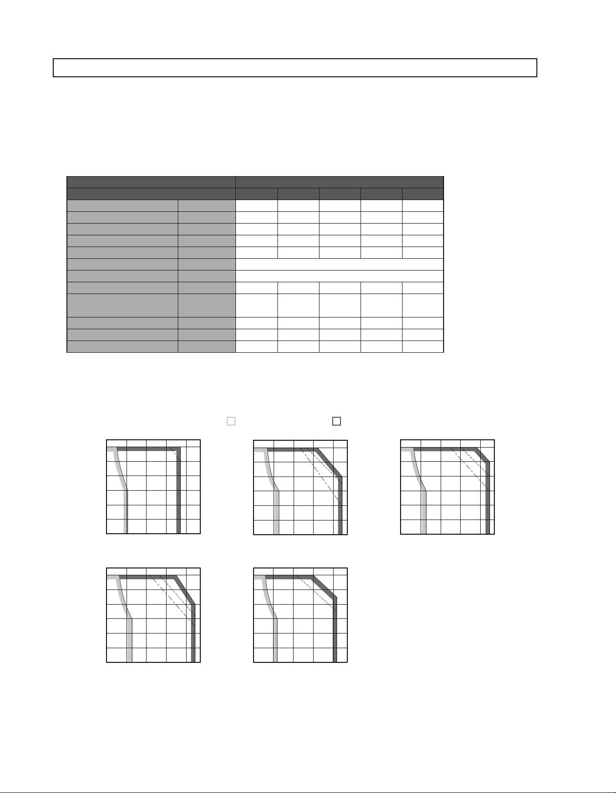
1Torque-Motor Speed Characteristics
A
: Continuous Duty Zone B: Intermittent Duty Zone
(Note3)
SGMJV-A5A SGMJV-01A SGMJV-02A
6000
)
-1
5000
min
(
4000
3000
AB AB
2000
Motor Speed
1000
0
0
0
15 0.30.45 0.6
.
Torque (Nûm
)
SGMJV-04A
6000
)
-1
5000
min
(
4000
3000
AB
2000
Motor Speed
1000
0
01 2 3 4
Torque (N
Notes: 1 The solid, dotted, and dashed-dotted lines of the intermittent duty zone indicate the characteristics when a servomotor runs with the following combinations:
• The solid line: With a three-phase 200 V or a single-phase 230 V SERVOPACK
• The dotted line: With a single-phase 200 V SERVOPACK
• The dashed-dotted line: With a single-phase 100 V SERVOPACK
An SGMJV-A5A servomotor has the same characteristics in combination with three-phase 200 V and single-phase 200 V SERVOPACKs.
2 The characteristics of the intermittent duty zone differ depending on the supply voltages.
3 When the effective torque during intermittent duty is within the rated torque, the servomotor can be used within the intermittent duty zone.
4 When the main circuit cable length exceeds 20 m, note that the intermittent duty zone of the Torque-Motor Speed Characteristics will shrink as the line-to-line
voltage drops.
)
û
m
6000
)
-1
5000
min
(
4000
3000
2000
Motor Speed
1000
0
00
25 0.50.75 1
.
Torque (N
SGMJV-08A
6000
)
-1
5000
min
(
4000
3000
AB
2000
Motor Speed
1000
0
02 468
Torque (Nûm
)
û
m
)
6000
)
-1
5000
min
(
4000
3000
2000
Motor Speed
1000
0
00
AB
51 1.52
.
Torque (N
)
û
m
3
Servomotors
SGMJV
Ratings and Specifications
1Derating Rate for Servomotor Fitted with an Oil Seal
When a motor is fitted with an oil seal, use the following derating rate because of the higher friction torque.
Rotary Motors
Servomotor Model
SGMJV-
Derating Rate % 80 90 95
A5A 01A 02A 04A 08A
1Holding Brake Electrical Specifications
Holding Brake
Rated Voltage
+
10%
24 VDC
0
Notes: 1 The holding brake is only used to hold the load and cannot be used to stop the servomotor.
2 The holding brake open time and holding brake operation time vary depending on which discharge circuit is used. Make sure holding brake open time and holding brake
operation time are correct for your servomotor.
3 A 24-VDC power supply is provided by customers.
Servomotor
Model
SGMJV-A5A 50 5.5 0.159 103 0.23 60 100
SGMJV-01A 100 5.5 0.318 103 0.23 60 100
SGMJV-02A 200 6 0.637 97.4 0.25 60 100
SGMJV-04A 400 6 1.27 97.4 0.25 60 100
SGMJV-08A 750 6.5 2.39 87.7 0.27 80 100
Servomotor
Rated Output
W
CapacityWHolding
Torque N·m
Holding Brake Specifications
Coil Resistance
Rated Current
Ω(at 20˚C)
A(at 20˚C)
Brake Release
Time ms
Brake Operation
Time ms
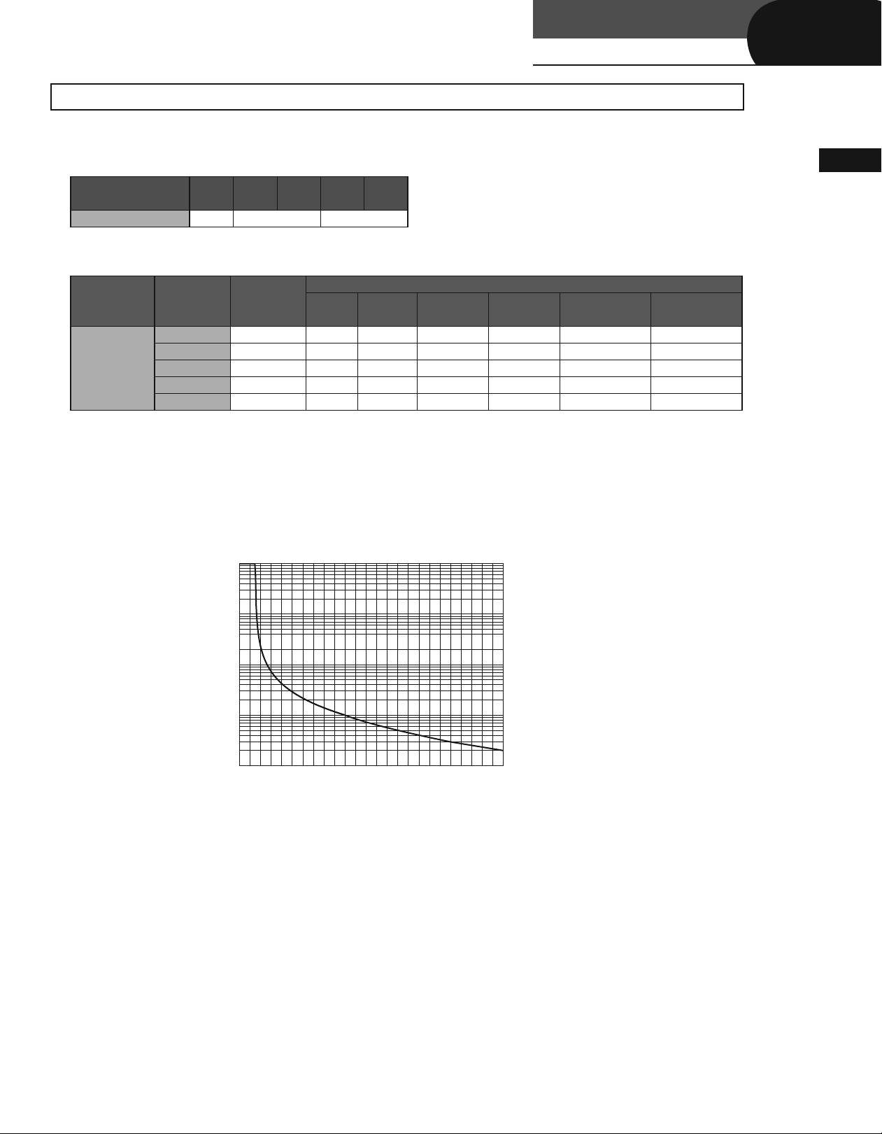
1Overload Characteristics
The overload detection level is set under hot start conditions at a servomotor ambient temperature of 40˚C.
10000
Rotary Servomotors
1000
Detecting time (s
Note: Overload characteristics shown above do not guarantee continuous duty of 100%
or more output. Use a servomotor with effective torque within the continuous duty
zone of Torque-Motor Speed Characteristics.
)
100
10
1
100 150 250200 300 350
Torque reference (percent of rated torque
(%)
)
4

Ratings and Specifications
Ratings and Specifications
1Allowable Load Moment of Inertia at the Motor Shaft
The rotor moment of inertia ratio is the value for a servomotor without a gear and a holding brake.
Servomotor Model
SGMJV-
Servomotor Rated
Output
A5A, 01A 50 ,100 W 20 times
02A 200 W 15 times
04A, 08A 400 to 750 W 10 times
Allowable Load Moment of Inertia
(Rotor Moment of Inertia Ratio)
1Load Moment of Inertia
The larger the load moment of inertia, the worse the movement response.
•
The allowable load moment of inertia (
•
each servomotor (
Use the AC servo drive capacity selection program SigmaJunmaSize+ to check the operation conditions. The program can be
•
JM). This value is provided strictly as a guideline and results may vary depending on servomotor drive conditions.
downloaded for free from our web site (http://www.e-mechatronics.com/).
An overvoltage alarm (A.400) is likely to occur during deceleration if the load moment of inertia exceeds the allowable load moment of
•
inertia. SERVOPACKs with a built-in regenerative resistor may generate a regenerative overload alarm (A.320). Take one of the following
steps if this occurs.
• Reduce the torque limit.
• Reduce the deceleration rate.
• Reduce the maximum speed.
• Install an external regenerative resistor if the alarm cannot be cleared using the steps above. Refer to Regenerative Resistors on
page 293.
Regenerative resistors are not built into SERVOPACKs for 400 W motors or less.
•
External regenerative resistors are required when this condition is exceeded or if the allowable loss capacity (W) of the built-in
•
regenerative resistor is exceeded due to regenerative drive conditions when a regenerative resistor is already built in.
JL) depends on motor capacity and is limited to within 5 to 30 times the rotor moment of inertia of
1Allowable Radial and Thrust Loads
Design the mechanical system so thrust and radial loads applied to the servomotor shaft end during operation fall within the
ranges shown in the table.
Servomotor Model
SGMJV-
Allowable Radial
Load (Fr) N
A5A
78 54 20
01A
02A
245 74 25
04A
08A 392 147 35
Allowable Thrust
Load (Fs) N
LR
mm
Reference Diagram
LR
Fr
Fs
5
 Loading...