

400V Large Capacity Sigma II Servo System
Dimensions in inches (mm)
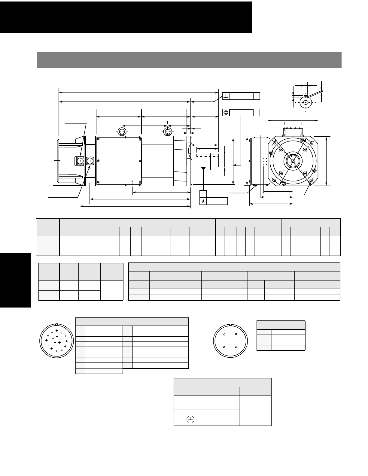
(1) 17 Bit Incremental / Absolute Encoder
W
Type
SGMBH
2BD A61
SGMBH
3ZD A61
Servomotor
SGMBH
Type
SGMBH-
2BD A61
3ZD A61
Encoder Plug Fan Connector
L
K
J
Fan connector
LD
L
LL
LN
LF
LP
LG
LE
LR
Q
QK
Y
0.0020 (0.05)
0.0020 (0.05)
ΦS
ΦLB
A
A
J
T
Cross-section Y-Y
LC
CK1
CK2
Φ
L
H
Y
Encoder connector
KB2
KB1
KG
A
0.0012 (0.03)
Power wiring
Φ2.40 (Φ61)
Motor Body Dimensions Flange Dimensions Shaft End Dimension
L LL LR LD LF LN LP KB1 KB2 KG KN KS KT CK1 CK2 J ΦLA ΦLB** LC LE LG ΦLH ΦLZ ΦS* Q QK W**** T*** U
29.13
23.62
(740)
(600)
5.51
31.91
(810)
Approximate
Note: 1. Dimensions are the same when using either incremental or absolute encoders (with or without optional shaft seal)..
2. Tolerances on the dimensions of flange type LB, of shaft extensions S, and of keyway width and depth are based on JIS (Japanese Industrial Standard)
(140)
26.38
(670)
Allowable
Mass
Radial Load
lb (kg)
264.5
(120)
308.7
(140)
B0401 “Limits and Fits for Engineering.”
lb (N)
1323
(5880)
1410
(6272)
9.06
(230)
6.97
6.30
(177)
(160)
9.65
9.06
(245)
(230)
Allowable
Thrust Load
lb (N)
485
(2156)
17.17
19.06
4.57
(116)
(436)
19.86
(504)
(484)
21.75
(552)
8.82
(224)
11.50
(292)
8.66
(220)
6.42
(163)
5.87
(149)
1.77
(45)
1.77
(45)
9.84
(250)
10.43
(265)
9.06
(230)
9.84
(250)
0.20
(5)
0.79
(20)
Specified Tolerances
Dimension *ΦS **ΦLB ***T ****W
Unit Diameter To le ra n ce Diameter Tolerance Length Tolerance Length Tolerance
in 2.362 +0.00118 -0.00043 9.055 +0.0000 -0.00181 0.433 +0.0000 -0.00043 0.709 +0.0000 -0.00169
mm 60 +0.030 -0.011 230 +0.000 -0.046 11 +0.000 -0.1103 18 +0.000 -0.043
Connector Wiring on the Encoders
A
M
N
P
T
R
S
H
G
A—K—
B
B—L—
C
C Data + M—
D
DData − N—
E
E—P—
F
F—R—
G0VS Battery − (Note*)
H
J FG (Frame Ground) *Note: Used with an absolute encoder only.
Non-Environmental Mating Connector:
MS3108B20-29S (L Type)
MS3106B20-29S (Straight Type)
Cable Clamp: MS3057-12A
+5V
dc
T Battery + (Note*)
A
D
B
C
Receptacle: CE05-2A18-10PD-B
Non-environmental mating connector:
Cable Clamp: MS3057-10A
Power Wiring Terminal Box
Terminal Connection Screw Size
KT
KS
KN
11.81
0.53
2.36
(300)
(13.5)
(60)
5.51
(140)
Fan Connector
AU Phase
B V Phase
C W Phase
D—
MS3108B18-10S (L-Type)
U
A
L
Φ
LC
4 - ΦLZ
4.33
0.71
0.43
(110)
(18)
(11)
0.28
(7)
154
U, V, W
Motor
M10
Ground
400V Large Capacity Sigma II Servo System
_
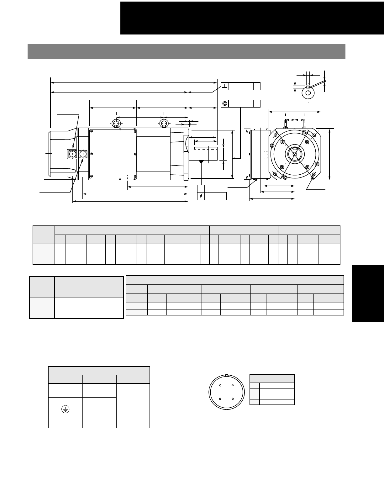
(2) 17 Bit Incremental/Absolute Encoder, with Brake
W
L
LL
LD
LP
LG
LE
LR
Q
QK
Y
Fan connector
LF
LN
Y
Encoder connector
KG
KB1
KB2
A
0.0012 (0.03)
Type
SGMBH-
2BD A6C
3ZD A6C
Type
SGMBH-
2BD A6C
3ZAD A6C
L LL LR LD LF LN LP KB1 KB2 KG KN KS KT CK1 CK2 J ΦLAΦLB** LC LE LG ΦLH ΦLZ ΦS* Q QK W**** T*** U
33.86
28.35
(860
(720)
36.64
31.13
(930)
(790)
Approximate
Mass
lb (kg)
331
(150)
375
(170)
6.97
(177)
5.51
(140)
9.65
(245)
Allowable
Radial Load
lb (N)
1323
(5880)
1410
(6272)
Motor Body Dimensions Flange Dimensions Shaft End Dimension
15.47
(393)
9.06
(230)
18.16
(461)
Allowable
Thrust Load
lb (N)
21.89
23.78
4.57
(116)
(556)
24.57
(624)
(604)
26.46
(672)
8.82
(224)
11.5
(292)
8.66
(220)
6.42
(163)
5.87
(149)
1.77
(45)
0.98
(25)
9.84
(250)
10.43
(265)
Specified Tolerances
Dimension *ΦS **ΦLB ***T ****W
Unit Diameter Tolerance Diameter Tolerance Length Tolerance Length Tolerance
485
(2156)
in 2.362 +0.00118 -0.00043 9.055 +0.0000 -0.00181 0.433 +0.0000 -0.00043 0.709 +0.0000 -0.00169
mm 60 +0.030 -0.011 230 +0.000 -0.046 11 +0.000 -0.1103 18 +0.000 -0.043
Note: 1. Dimensions are the same when using either incremental or absolute encoders (with or without optional shaft seal)..
2. Tolerances on the dimensions of flange type LB, of shaft extensions S, and of keyway width and depth are based on JIS (Japanese Industrial Standard)
B0401 “Limits and Fits for Engineering.”
0.0020 (0.05)
ΦS
Power wiring
Φ2.40 (Φ61)
9.06
(230)
0.0020 (0.05)
ΦLB
9.84
0.20
(250)
(5)
A
A
J
KN
0.79
11.81
(300)
0.53
(13.5)
(20)
T
Cross-section Y-Y
LC
CK1
CK2
KS
KT
2.36
(60)
Φ
A
L
L
H
Φ
5.51
4.33
(140)
(110)
4 - ΦLZ
0.71
(18)
0.43
(11)
LC
0.28
(7)
SGMBH
Servomotor
U
Power WiringTerminal Box
Terminal Connection Screw Size
U, V, W Motor
M10
Ground
A
D
B
C
Fan Connector
A U Phase
B V Phase
CW Phase
D Ground Terminal
Receptacle: CE05-2A18-10PD-B
Non-environmental mating connector:
A, B Brake M4
MS3108B18-10S (L-Type)
Cable Clamp: MS3057-10A
155

400V Large Capacity Sigma II Servo System
_
(3) 17 Bit Incremental/Absolute Encoder
0.0020 (0.05) A
Fan connector
LD
LL
LN
L
LF
LP
LE
LG
Φ
0.0020 (Φ0.05)
W
T
A
Cross-section Y-Y
LC
CK1
CK2
U
Type
SGMBH-
3GD A61
4ED A61
SGMBH
Servomotor
SGMBH
.
Type
SGMBH-
3GD A61
4ED A61
Encoder Plug Fan Connector
L
K
J
Q
QK
Y
J
ΦS
ΦLB
Φ
A
L
H
ΦL
Y
KG
Encoder connector
L LL LD LF LN LP KB1 KB2 KG KN KS KT CK1 CK2 J ΦLA ΦLB** LC LE LG ΦLH ΦLZ ΦS* Q QK W**** T*** U
32.0
26.5
(814)
(674)
33.7
28.1
(855)
(715)
Approximate
Mass
lb (kg)
507.1
(230)
551.1
(250)
Note: 1. Dimensions are the same when using either incremental or absolute encoders (with or without optional shaft seal)..
2. Tolerances on the dimensions of flange type LB, of shaft extensions S, and of keyway width and depth are based on JIS (Japanese Industrial Standard)
9.45
5.91
(240)
lb (N)
1674
(7448)
1762
(7840)
11.1
(281)
(150)
7.87
(200)
Allowable
Thrust Load
lb (N)
485
(2156)
9.29
(236)
Allowable
Radial Load
B0401 “Limits and Fits for Engineering.”
KB1
KB2
Motor Body Dimensions Flange Dimensions Shaft End Dimension
20.1
22.0
7.87
(200)
(510)
21.7
(551)
11.6
(558)
(295)
8.66
7.91
(201
6.85
(174)
23.6
(599)
Dimension *ΦS **ΦLB ***T ****W
(220)
13..2
(336)
Unit Diameter Tolerance Diameter To l er a nc e Length Tolerance Length To l er a nc e
in 2.76 +0.0012 -0.004 9.84 +0.0000 -0.0018 0.47 +0.0000 -0.00433 0.79 +0.0000 -0.00204
mm 70 +0.030 +0.011 250 +0.000 -0.046 12 +0.000 -0.110 20 +0.000 -0.052
2.36
(60)
A
2.36
(60)
Power wiring
Φ2.40 (Φ61)
0.0012 (0.03)
8.66
11.8
(220)
(300)
9.84
11.8
(300)
0.20
(5)
(250)
Specified Tolerances
Connector Wiring on the Encoders
A
M
B
N
C
P
T
H
D
R
S
E
F
G
A—K—
B—L—
C Data + M—
DData − N—
E—P—
F—R—
G0VSBattery − (Note*)
H
J FG (Frame Ground) *Note: Used with an absolute encoder only.
Non-Environmental Mating Connector:
MS3108B20-29S (L Type)
MS3106B20-29S (Straight Type)
Cable Clamp: MS3057-12A
+5V
dc
T Battery + (Note*)
Terminal Connection Screw Size
A
D
B
C
Power Wiring Terminal Box
1.38
(35)
KN
KT
KS
13.8
(350)
0.69
(17.5)
2.76
(70)
4 - ΦLZ
5.51
(140)
4.33
(110)
Fan Connector
AU Phase
B V Phase
C W Phase
D—
Receptacle: CE05-2A18-10PD-B
Non-environmental mating connector:
MS3108B18-10S (L-Type)
Cable Clamp: MS3057-10A
LC
0.79
(20)
0.47
(12)
0.29
(7.5)
156
U, V, W Motor
M10
Ground

400V Large Capacity Sigma II Servo System
_
(4) 17 Bit Incremental/Absolute Encoder
0.87 (22) = W
0.35 (9)
0.55 (14) = T
Cross-section Y-Y
38.19 (970)
31.50 (800)
Fan connector
Encoder connector
Approximate
Type SGMBH
Mass
lb (kg)
5ED AL1 772 (350) 1895 (8428) 485 (2156)
Note: 1. Dimensions are the same when using either incremental or absolute encoders
(with or without optional shaft seal)..
2. Tolerances on the dimensions of flange type LB, of shaft extensions S, and of keyway width
and depth are based on JIS (Japanese Industrial Standard)
B0401 “Limits and Fits for Engineering.”
26.93 (684)
12.32 (313)
Φ2.40 (Φ61)
15.98 (406)
Allowable Radial
Load
lb (N)
16.57 (421)
14.41 (366)9.29 (236)
7.87 (200)
0.20 (5)
4.75 (121)
Allowable Thrust Load
lb (N)
6.69 (170)
6.69 (170)
Y
10.24 (260)
(Φ80)
Φ3.15
Y
7.09 (180)
A
0.0012 (0.03)
Dimension *T *W
Unit Length Tolerance Length Tolerance
in 0.55 +0.0000 -0.00433 0.87 +0.0000 -0.00204
mm 14 +0.000 -0.110 22 +0.000 -0.052
Encoder Plug Fan Connector
A
M
B
N
L
K
J
H
C
P
T
D
R
S
E
F
G
A—K—
B—L—
C Data + M—
DData − N—
E—P—
F—R—
G0VS Battery − (Note*)
H
J FG (Frame Ground) *Note: Used with an absolute encoder only.
Non-Environmental Mating Connector:
MS3108B20-29S (L Type)
MS3106B20-29S (Straight Type)
Cable Clamp: MS3057-12A
Connector Wiring on the Encoders
+5V
dc
T Battery + (Note*)
D
C
Power Wiring Terminal Box
Te rm i n al Connection Screw Size
0.0020 (0.05) A
Φ
0.0020 (Φ0.05)
7.91 (201)
3.54 (90)
5.49 (139.5)
A
12.99 (330)
11.81 (300)
8.66 (220)
5.49 (139.5)
12.99 (330)
Specified Tolerances
Fan Connector
A
B
A U Phase
B V Phase
C W Phase
D—
Receptacle: CE05-2A18-10PD-B
Non-environmental mating connector:
MS3108B18-10S (L-Type)
CableClamp: MS3057-10A
Power wiring
Ι
(
Ι
4-Φ0.94
(Φ24)
13.8
350
)
SGMBH
Servomotor
U, V, W Motor
Ground
M10
157
 Loading...