

Page 1
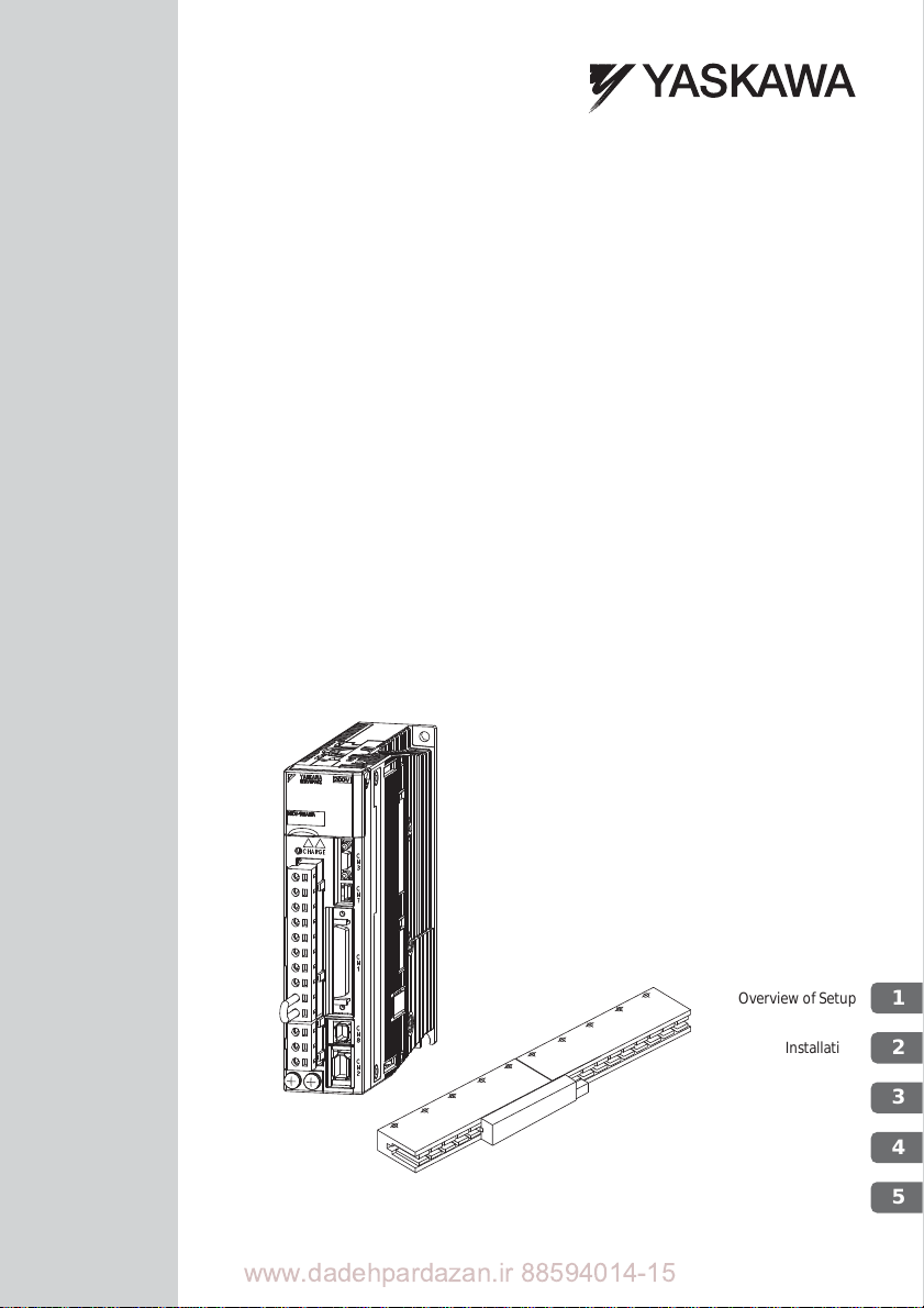
AC Servo Drives
-V Series
USER'S MANUAL
Setup
Linear Motor
SGDV SERVOPACK
SGLGW/SGLFW/SGLTW/SGLC/SGT Linear Servomotors
(Checking Linear Servomotor Operation)
MANUAL NO. SIEP S800000 44D
www.dadehpardazan.ir 88594014-15
Overview of Setup
Installation
Wiring and Connection
Safety Function
Trial Operation
1
2
3
4
5
Page 2

ﺖﮐﺮﺷاوﺎﮑﺳﺎﯾ :ﯽﺘﻌﻨﺻ نﻮﯿﺳﺎﻣﻮﺗا تﻻﻮﺼﺤﻣ عاﻮﻧا هﺪﻨﻨﮐ ﺪﯿﻟﻮﺗ
- ﯽﺘﻌﻨﺻ يﺎﻫ تﺎﺑر
- رود لﺮﺘﻨﮐ يﺎﻫﺮﺗرﻮﻨﯾا عاﻮﻧا
- وﺮﺳ يﺎﻫ ﻢﺘﺴﯿﺳ
- Motion Controller
- PLC
ﺎﯿﻠﯾا ﺪﻨﻤﺷﻮﻫ نازادﺮﭘ هداد ﺖﮐﺮﺷ و يا ﻪﻓﺮﺣ ﯽﻧﺎﺒﯿﺘﺸﭘ تﺎﻣﺪﺧ ﻪﺋارا هﺪﻨﻨﮐ ﻦﯿﻣﺎﺗ
ﺠﺗﯿﻬ تاﺰYaskawa
ﯽﺷزﻮﻣآ يﺎﻫ هرود يراﺰﮔﺮﺑPLC – HMI – Servo – Sensor – Inverter – Industrial Network
ﯽﺘﻌﻨﺻ نﻮﯿﺳﺎﻣﻮﺗا يﺎﻫژوﺮﭘ مﺎﺠﻧا
ﯽﺘﻌﻨﺻ نﻮﯿﺳﺎﻣﻮﺗا تاودا ﻪﯿﻠﮐ ﯽﺼﺼﺨﺗ تاﺮﯿﻤﻌﺗ
: سﺎﻤﺗ يﺎﻫ ﻦﻔﻠﺗ15-88594014 : ﺲﮑﻓ88594013
بو : ﺖﯾﺎﺳwww.dphi.ir – www.indus.ir
Page 3

Copyright © 2007 YASKAWA ELECTRIC CORPORATION
All rights reserved. No part of this publication may be reproduced, stored in a retrieval
system, or transmitted, in any form, or by any means, mechanical, electronic, photocopying, recording, or otherwise, without the prior written permission of Yaskawa. No
patent liability is assumed with respect to the use of the information contained herei n.
Moreover, because Yaskawa is constantly striving to improve its high-quality products,
the information contained in this manual is subject to change without notice. Every
precaution has been taken in the preparation of this manual. Nevertheless, Yaskawa
assumes no responsibility for errors or omissions. Neither is any liability assumed for
damages resulting from the use of the information contained in this publication.
www.dadehpardazan.ir 88594014-15
Page 4
About this Manual
This manual describes procedures required for installation, wiring, and connecting
-V Series servo drives, including a JOG operation for linear servom
otors not con-
nected to machinery.
Be sure to refer to this manual and perform setup
operations correctly.
Keep this manual in a location where it can be accessed for reference whenever
required.
Description of Technical Terms
The following table shows the meanings of terms used in this manual.
Term Meaning
Cursor Input position indicated by Digital Operator
Linear Servomotor
SERVOPACK -V Series SGDV SERVOPACK
Servo Driv
Servo System
Analog Pulse Model
M-II
M-III Model
Command Option
Attachable T
Servo ON Power to motor ON
Servo OFF Power to motor OFF
Base Block (BB)
Linear Scale Connection
Cables
Mod
e
el
ype
-V Series SGLGW, SGLFW, SGL T W, or SGLC linear servomotor,
or SGT linear slider
A set including a linear servomotor and SERVOPACK (i.e., a
servo amplifier)
A servo control system that includes the combinatio
drive with a host controller and peripheral devices
Analog voltage and pulse-train reference used for SERVOPACK
interface.
ME
CHATROLINK-II communications reference used for
SERVOPACK interface.
MECHATROLINK-III communications reference used for
SERVOPACK interface.
SERVOPACK for which a command option module can be
installed.
OFF by shutting off the base cur-
Power supply to motor is tur
rent to the power transistor in the current amplifier.
set of cables including a cable for
A
unit, a cable for connecting linear scale, and a cable for connecting hall sensor
ned
connecting serial converter
n of
a servo
www.dadehpardazan.ir 88594014-15
iii
Page 5
IMPORTANT Explanations
The following icon is displayed for explanations requiring special attention.
Notation Used in this Manual
In this manual, the names of reverse signals (ones that are valid when low) are written
with a forward slash (/) before the signal name, as shown in the following example:
Example
S-ON = /S-ON
Manuals Related to the -V Series
Refer to the following manuals as required.
Name
-V Series
Product Catalog
(KAEP S800000 42
-V Series
User's Manual
Desig
n and
Maintenance
Linear Motor/Analog
age and Pulse
Volt
Train Reference
(SIEP S800000 47)
-V Series
User's Manual
Design and
Maintenance
Linear Motor/
MECHATR
Communications
Reference
(SIEP S800000 48)
-V Series
User’s Manual
MECHATROLINK-II
Command
(SIEP S800000 54)
OLINK-II
• Indicates important information that shou
precautions, such as alarm displays, that do not involve potential damage
to equipment.
Selecting
Models
and
Peripheral
Devices
)
Ratings
and
Specifi-
cations
System
Design
Panels
and
Wiring
ld be memorized, as well as
Trial
Trial
Operation
Operation
and
Servo
Adjustment
Maintenance
and
Inspection
*
*
iv
www.dadehpardazan.ir 88594014-15
Page 6

Name
-V Series
User’s Manual
Operation of Digital
Operator
(SIEP S8000
-V Series
User
MECHATROLINK-III
Command
(SIEP S800000 63)
-V Series
User's Manual
Design and
Maintenance
Linear M
MECHAT
Communications
Reference
00 55)
’s Manual
otor/
ROLINK-III
(SIEP S800000 65)
-V Series
User's Manual
Design and
Maintenance
Linear Motor/
Command Op
Attachable Type
(SIEP S800000 66)
-V Series
User's Manual
Indexer Module
(SIEP C7
-V Series
User's Manual
EtherCAT (CoE)
Network Module
(SIEP C720829 04)
AC SERVOMOTOR
Safety Precautions
(TOBP C230200 00)
-V Series
AC SER
SGDV Safety
Precautions
(TOBP C710800 10)
tion
20829 02)
VOPACK
-V Series
Option Module
Safety Precautions
(TOBP C720
829 00)
Selecting
Models
and
Peripheral
Devices
Ratings
and
Specifi-
cations
System
Design
Panels
and
Wiring
Trial
Operation
Trial
Operation
and
Servo
Adjustment
(cont’d)
Maintenance
and
Inspection
*
*
*
www.dadehpardazan.ir 88594014-15
v
Page 7

Name
-V Series
Command Option
Module
Installation Guide
(TOBP C720829 01)
-V Series
Indexer Mo
Installation Guide
(TOBP C720829 02)
-V Series
Feed
Module
Installation Guide
(TOBP C720829 03)
Series
Digital Operator
Safety Precautions
(TOBP C730800 00)
dule
back Option
Refer to these manuals for troubleshooting of problems which may occur during setup.
(Tro
User's Manual Design and Maintenance Linear Motor/Command Option Attachable Type
(SIEP S800000 66).
(cont’d)
Selecting
Models
and
Peripheral
Devices
ubleshooting which is common for command option modules is described in -V Series
Ratings
Specifi-
cations
and
System
Design
Panels
and
Wiring
Trial
Operation
Trial
Operation
and
Servo
Adjustment
Maintenance
and
Inspection
vi
www.dadehpardazan.ir 88594014-15
Page 8
Safety Information
WARNING
CAUTION
PROHIBITED
MANDATORY
The following conventions are used to indicate precautions in this manual. Failure to
heed precautions provided in this manual can result in serious or possibly even fatal
injury or damage to the products or to related equipment and systems.
Indicates precautions that, if not heeded, could
possibly result in loss of life or serious injury.
Indicates precautions that, if not heeded, could result
in relatively serious or minor injury, damage to the
product, or faulty operation.
In some situations, the precautions indicated could
have serious con
Indicates prohibited actions that must not be
performed. For example, this symbol would be used to
indicate that fire is prohibited as follows:
Indicates compulsory actions that must be performed.
For example, this symbol would be used as follows to
indicate that grounding is compulsory:
seque
nces if not heeded.
vii
www.dadehpardazan.ir 88594014-15
Page 9

Safety Precautions
These safety precautions are very important. Read them before performing any procedures such as checking products on delivery, storage
tion, wiring, operation and i
nspection, or disposal. Be sure to always observe these
and transportation, installa-
precautions thoroughly.
WARNING
• If you have a pacemaker or any other electronic medical device, do not go
near the magnetic way of the linear servomotor.
Failure to observe this warning may result in the malfunction of the medical
device.
e sure to use nonmagnetic tools when installing or working close to the
• B
linear servomoto
(Example: a beryllium-copper alloy hexagonal wr
Insulators, Ltd.)
• Never touch the linear servomotor or machinery during operation.
• B
• Before wiring, install the SERVOPACK and the linear servomotor.
• Never touch the inside of the SERVOPACKs.
• Do not remove the cover of the power supply terminal while the power is
• After the power is turned OFF or after a voltage resistance test, do not
• Follow the procedures and instructions provided in this manua
• Do not remove the front cover, cables, connector
• Do not damage, press, exert excessive force on, or place heavy objects on
• Do not modify the product.
o observe this warning may result in injury.
Failure t
efore starting operation with a machine connected, make sure that an
emergency stop can be applied
Failure to observe this warning may result in injury or damage to the product.
Failure to observe this warning may result in electric shock.
Failure to observe this warning may result in electric shock.
.
ON
Failure to
terminals while the charge
touch
Residual voltage may cause electric shock.
operation.
Failure t
o do so may result not only in faulty operation and damage to equipment,
but also in personal injury.
the upper front of the SERVOPACK while the power is ON.
Failure to observe this warning may result in electric shock.
the cables.
Failure to observe this warning may result in electr
the product, or fire
Failure to observe this warning may result in injury, fire, or damage to the product.
r.
at any time.
observe this warning may result in electric shock.
indicator is ON.
ench set, made by NGK
s, or
ic sh
ock, stopping operation of
.
l for trial
optional items from
viii
www.dadehpardazan.ir 88594014-15
Page 10
WARNING
• Provide an appropriate braking device on the machine side to ensure
safety.
Failure to observe this warning may result in injury.
• Do not come close to the machine immediately after resetting a momentary
power loss. T
sures to ensure safety against an unexpected restart.
Failure to observe this warning may result in injury
• Connect the ground terminal according to local electrical codes (100 or
less f
SERVOPACK with a 400 V power supply.)
Improper grounding may result in electric shock or fire.
• Installation, disassembly, or repair must be performed only by authorized
personnel.
Failure to observe this warning may result in electric
• The person who designs a system using the safety fu
Base Block function) must have full knowledge of the related safety standards and full understanding of the instructions in
ual Design and Maintenance (SIEP S800000 47/48/65/66).
Failure to observe this warning may result in injury or damage to the product.
he machine may restart unexpectedly. Take appropriate mea-
.
or a SERVOPACK with a 100, 200 V power supply. 10 or less for a
shock or injury
-V Series User’s Man-
.
nction (Hard Wire
www.dadehpardazan.ir 88594014-15
ix
Page 11
Storage and Transportation
CAUTION
• Be sure to store the magnetic way in the package that was used for delivery.
• Do not store or install the product in the following locations.
Failure to observe this caution ma
product.
• Locations subject to direct sunlight
• Locations subject to temperatures outside the range
installation temperature conditions
• Locations subject to humidity outside the range spec
lation humidity conditions
• Locations subject to condensation as the result of extreme changes in temperature
• Locations subject to corrosive or flammable gases
• Locations subject to dust, salts, or iron dust
• Locations subject to exposure to
• Locations subject to shock or vibration
• Do not carry the linear servomotor by its cables.
Failure to observe this caution may result in injury or malfunction.
Do not place any load exceeding the limit specified on the pa
•
Failure to observe this caution may result in injury or malfunction.
If disinfectants or insecticides must be used to treat pa
•
as wooden frames, pallets, or plywood, the packing materials must be
treated before the product is packaged, and methods other than fumigation
must be used.
Example: Heat treatment, where materials are kiln-dried to a core temper
If the electronic products, which include stand-alone products and products
installed in mach
components may be greatly damaged by the gases or fumes resulting from the
fumigation process. In particular, disinfectants contain ing halogen, which includes
chlorine, fluorine, bromine, or iodine can contribute to the erosion of the capacitors.
ture of 56C for 30 minutes or more.
ines, are packed with fumigated wooden materials, the electrical
y resu
lt in fire, electric shock, or damage to the
specified in the storage/
ified in the storage/instal-
water,
oil, or chemicals
cking box.
cking materials such
a-
Installation
CAUTION
• When unpacking and installing magnetic way, check that no metal fragments or magnetized objects near the magnetic because they may be
affected by the magnetic attraction of the magnetic way.
Failure to observe this caution may result in
way's magnets.
• Do not use the magnetic way near metal or other magnetized objects.
Failure to observe this caution may result in
x
injury or damage to the magnetic
injury.
www.dadehpardazan.ir 88594014-15
Page 12
Installation (cont’d)
Cover
Magnetic way
• Do not place clocks, magnetic cards, floppy disks, or measuring instruments close to the magnetic way.
Failure to observe this caution may result in malfunction or dama
by the magnetic force.
• Securely mount the linear servomotor onto the machine.
If the linear servomotor is not mounted securely
• Do not carry the magnetic way by its magnet protection cover.
Failure to observe this caution may result in injury by the cove
of the cover may become distorted.
CAUTION
ge to these items
, it may loosen during
r’s edge or the shape
operation.
• When removing the dummy plate for reducing magnetic force used for the
W magnetic way, pay attention to the magnetic attraction of the mag-
SGLF
netic way. Do not place the removed plate close to the magnetic way.
Failure to observe this caution may result in injury or damage to the magnetic
way’s magn
• Install SERVOPACKs, linear servomotors, and regenerative resistors on
nonflammable objects.
Installation di
• Never use the product in an environment subject to water,
inflammable gases, or combustibles.
Failure to observe this caution may result in electric
• Do not step on or place a heavy object on the product.
Failure to observe this caution may result in injury or malfunction.
o not cover the inlet or outlet ports and prevent any foreign objects from
• D
entering the product.
Failure to observe
in malfunction or fire.
• Be sure to install the product in the correct direction.
Failure to observe this caution may result in malfunction.
rovide the specified clearances between the SERVOPACK and the con-
• P
trol panel or with other devices.
Failure to observe this caution may
• Do not apply any strong impact.
Failure to observe this caution may result in malfunction.
ets or the magnet protection cover.
rectly onto or near flamma
this caution may cause internal elemen
ble objects may result in fire.
result in fire or malfunc
corrosive gases,
shock or fire.
ts to deteriorate resulting
tion.
www.dadehpardazan.ir 88594014-15
xi
Page 13

Wiring
CAUTION
• Be sure to wire correctly and securely.
Failure to observe this caution may result in motor overrun, injur
• Securely tighten the cable connector screws and securing mechanism.
connector screws and securing mechanism are not secure, they may loosen
If the
during operation.
• Use cables with a radius, heat resistance, and flexibility suitable for
system.
• If the SERVOP ACK malfunctions, turn OFF the main circuit’s power supply
of the SER
The continuous flow of a large current may cause fire.
• Use a noise filter to minimize the effects of electromagnetic damage.
Failure to observe this caution ma
devices used near the SERVOPACK.
• Do not connect a commercial power supply to the U, V, or W terminals for
the linear servomotor connection.
Failure t
• Securely connect the main circuit power supply ter
motor connection terminals.
Failure to observe this caution may result in fire.
• Do not bundle or run the main circuit cables together with the I/O signal
cables or the linear scale
separated by at least 30 cm.
Failure to do so may result in malfunction.
• Use shielded twisted-pair wires or multiI/O signal cables and the linear scale connection cables.
• The maximum cable length is 3 m for the I/O signals, 20 m for the linear
ser
ear scale, 15 m for the hall sensor, and 10 m for control power supply
cables for the SERVOPACK with a 400-V power supply (+24 V, 0 V).
• Do not touch the power terminals while the charge indicator is ON after
turning powe
PACK.
Make sure the charge indicator is off first before starting wiring
• Be sure to observe the following precautions when wiring the SERVOPACK main circuit terminals has been completed.
• Do not turn
• Remove detachable main circuit terminals from the SERVOPACK prior to wir-
• Insert only one main circuit cable per opening in the main circ
• Make sure that no part of the core wire comes into contact with (i.e., short-cir-
• Do not connect the SERVOPACK for 200 V directly to a voltage of 400 V.
The SERVOPACK will be destroyed.
• Always use the specified power supply voltage:
Failure to observe this caution may result in fire or
VOPA
CK.
y res
ult in electromagnetic damage to electronic
o observe this caution may result in injury
connection cables in the same duct. Keep them
vomo
tor main circuit, 20 m for the serial converter unit, 15 m for the lin-
r OFF
because high voltage may still remain in the SERVO-
circuit terminals has been completed.
ing.
cuit) adjacent wires.
ON the power to the SERVOPA
or fire.
core
shielded twisted-pair wires for
CK until all wiring including main
product failure.
y, or m alf unction.
the
minals and linear servo-
and inspection.
uit terminals.
xii
www.dadehpardazan.ir 88594014-15
Page 14
Wiring (cont’d)
• Make sure that the polarity is correct.
Incorrect polarity may cause ruptures or damage.
• Take appropriate measures to ensure that the input power supply is supplied within the specified voltage fluctuation ra
places where the power supply is unstable.
An incorrect power supply may result in damage to the product.
• Install external breakers or other safety devices
external wiring.
Failure to observe this caution may result in fire.
• Take appropriate and sufficient countermeasures for each form of potential
interference
Failure to observe this caution may result in damage to the product.
ocations subject to static electricity or other forms of noise
• L
• Locations subject to strong electromagnetic fi
• Locations subject to possible exposure to radioactivity
• Locations close to power supplies
Failure to observe this caution may result in damage to the product.
iring or inspection must be performed by a technical expert
• W
• Use a 24 VDC power supply with double insulation or reinforced insulation
• Failures caused by incorrect wiring or wrong voltage application in the
brake circu
death or injury. Follow the procedures and instructions for wiring and trial
operation precisely as described in this manual.
• Leakage current may increase depending on the type of noise filter and the
nding conditions.
grou
When using a detector or
priate one by considering the type of noise filter an
For details, contact the manufacturer of the noise filter.
• Incorrect wiring or incorrect voltage application to the output circuit may
use short-circuit.
ca
The above failures will prevent the holding
age the machine or cause an accident resulting in death or injury.
• Inverting the polarity of the brake signal (/BK), i.e. positive logic, will pre-
the holding brake from working in case of its signal line disconnection.
vent
If this settin
there are no safety problems.
CAUTION
nge. Be particu
against short-
when installing systems in the following locations.
elds and magnetic fields
it may damage the equipment or cause an accident resulting in
a breaker for leakage current, select the appro-
d the ground conditions.
brake from working, which may dam-
g is absolutely necessary, check the operation and confirm that
larly careful in
circuiting in
.
Operation
• Do not stand within the machine's range of motion during operation.
•
www.dadehpardazan.ir 88594014-15
CAUTION
Failure to observe this caution may result in injury.
Always use the linear servomotor and SERVOPACK in one of the specified
combinations.
Failure to
observe this caution may result in fire or malfunction.
xiii
Page 15
Operation (cont’d)
CAUTION
• If the SERVOPACK, the absolute linear scale, or the linear servomotor is
replaced, the polarity detection function must be executed again.
Failure to observe this caution may result in the linear ser
unpredictable manner.
• Before operation, install a limit switch or stopper on the end of th
prevent unexpected movement.
Failure to observe this caution may result in
• During trial operation, confirm that the holding brake works corr
thermore, secure system safety against problems such as signal line disconnection.
• Before starting operation with a machine
match the parameters of the machine.
Starting operation without matching the proper settings may cause the machine to
run out of control or malfunction.
• Do not frequently turn power ON and OFF.
• Frequently turning power ON and OFF causes elements inside the SER
to
deteriorate. Do not use the servo drive with an application that requires fre-
quently turning power ON and OFF.
• After the actual operation starts, the allowable interval for turnin
OFF is one hour or longer.
• When carrying out JOG operation (Fn002), origin search (Fn003), or
• When using the linear servomotor for a vertical axis, in
• When not using turning-less function, set the correct mass ratio (Pn103).
• Do not touch the SERVOPACK heatsinks, regenerative resistor, or linear
• Do not make any extreme adjustments or changes in the settings of param-
• If an alarm occurs, shut down the main circuit power supply.
• When an alarm occurs, remove the cause, reset the a
• An alarm or warning may be generated if communications are executed
T (Fn206), forcing movable machine parts to stop does not work for
EasyFF
forward overtravel or reverse overtravel. Take necessary precautions.
Failure to observe this caution may result in damage to
to prevent workpieces from falling due to alarms or overtravels. Set the linear servomotor so that it will stop in the zero clamp state when overtravel
occurs.
Failure to observe this caution may cau
Setting an incorrect mass ratio may cause machine vibration.
tor while power is ON or soon after the power is turned OFF.
servomo
Failure to observe this caution may result in burns due to high temperatur
eters.
Failure to observe this caution may result in injury
unstable operation.
Failure to observe this caution
heating caused by regenerative transistor failure.
safety, and then resume operation.
Failure to observe this caution may result in
with the host controller
operator.
If an alarm or warning is generated, the pr ocess curr
aborted and the system may stop
may
during operation using SigmaWin+ or the digital
injury.
connected, change
se workpieces to fall due to overtravel.
result in fire due to regenerative resistor over-
damage to the product, fire, or injury.
vomotor moving in an
e slider to
ectly. Fur-
the settings to
VOP ACK
g power ON and
the equipment.
stall safety devices
es.
or damage to the product due to
larm after confirming
ently being executed may be
xiv
www.dadehpardazan.ir 88594014-15
Page 16
Maintenance and Inspection
CAUTION
• Do not disassemble the linear servomotor.
Failure to observe this caution may result in electric
• Do not attempt to change wiring while the power is ON.
Failure to observe this caution may result in electric
• When replacing the SERVOP ACK, resume operation only after copying the
previous SERVOPA
Failure to observe this caution may result in damage to the product.
e sure to eliminate static electricity before operating
• B
inside the front cover.
Failure to observe this caution may result in damage to the product.
CK parameters to the new SERVOPACK.
shock or injury.
shock or injury.
buttons and switches
Disposal
CAUTION
• When disposing of the products, treat them as ordinary industrial waste.
General Precautions
Observe the following general precautions
to ensure safe application.
• The products shown in illustrations in this manual are sometimes shown without covers or protective guards. Always replace the cover or protective
first, and then operate the products in accordance with the manual.
• The drawings presented in this manual are typical examples and may not match the
product you received.
• If the manual must be ordered due to loss or damage,
representative or one of the offices listed on the back of this manual.
inform your nearest Yaskawa
guard as specified
www.dadehpardazan.ir 88594014-15
xv
Page 17
Warranty
(1) Details of Warranty
War ranty Period
The warranty period for a product that was purchased (hereinafter called “delivered
product”) is one year from the time of delivery to the location specified by the customer or 18 months from the time of shipment
is sooner.
War ranty Scope
Yaskawa shall replace or repair a defective product free of charge if a defect attributable to Yaskawa occurs during the warranty period
cover defects caused by the delivered product reaching the end of its service life and
replacement of parts that require replacement or that have a limited service life.
m the Yaskawa factory, whichever
fro
above. This warranty does not
This warranty does not cover fa
1. Improper handling, abuse, or use in unsuitable conditions or in environments not
described in product catalogs or manuals, or in any separately agreed-upon specifications
2. Causes not attributable to the delivered
3. Modifications or repairs not performed by Yaskawa
4. Abuse of the delivered product in a manner in which it was
intended
5. Causes that were not foreseeable with the scientific and technolog
standing at the time of shipment from Yaskawa
6. Events for which Yaskawa is not responsible, such as natural or human-made
disasters
ilures that result from any of the following causes.
product itself
not originally
ical under-
(2) Limitations of Liability
1. Y askawa shall in no event be responsible for any damage or loss of opportunity to
the customer that arises due to failure of the delivered product.
2. Y askawa shall not be responsible for any programs (including parameter settings)
the results of program execution of the programs provided by the user or by a
or
third party for use with programmable Yaskawa products.
3. The information described in product catalogs o
pose of the customer purchasing the appropriate product for the intended application. The use thereof does not guarantee that there are no infringements of
intellectual property rights or other proprietary rights of Yaskawa or third parties,
nor does it construe a license.
4. Yaskawa shall not be responsible for any
intellectual property rights or other proprietary rights of third parties as a result of
using the information described in catalogs or manuals.
r manuals is provided for the pur-
damage arising from infringements of
xvi
www.dadehpardazan.ir 88594014-15
Page 18

(3) Suitability for Use
1. It is the customer’s responsibility to confirm conformity with any standards,
codes, or regulations that apply if the Yaskawa product is used in combination
with any other products.
2. The customer must confirm that the Yaskawa product is suitable for the
machines, and equipment used by the customer.
3. Consult with Yaskawa to determine whether use in the
acceptable. If use in the application is acceptable, use the product with extra
allowance in ratings and specifications, and provide safety measures to minimize
hazards in the event of failure.
• Outdoor use, use involving potential chemical contamination or electrical
ference, or use in conditions or
or manuals
• Nuclear energy control systems, combustion systems, railroad systems, aviation systems, vehicle systems, medical equipme nt, amusement machines, and
installa
• Systems, machines, and equipment that may present a risk to life or property
• Systems that require a high degree of reliability
• Other systems that require a similar high degree of safety
4. Never use the product for an application involving serious risk to life or property
without first ensuring that the system is designed to secure the required level of
safety with risk warnings and redundancy, and that the Yaskawa product is properly rated and installed.
5. The circuit examples and other application examples described in product catalogs and manuals are for reference. Check the functionality and safety of the
actual devices and equipment to be used before using the product.
6. Read and understand all use prohibitions and
kawa product correctly to prevent accidental harm to third parties.
tions subject to separate industry or government regulations
gas, water, or electricity, or systems that operate continuously 24 hours a day
environments not described in product catalogs
precautions, and operate the Yas-
following applications is
, such as systems that supply
systems,
inter-
(4) Specifications Change
The names, specifications, appearance, and accessories of products in product catalogs and manuals may be changed at any time based on impr
sons. The next editions of the revised catalogs
updated code numbers. Consult with your Yaskawa representative to confirm the
actual specifications before purchasing a product.
or manuals will be published with
ovements and other rea-
www.dadehpardazan.ir 88594014-15
xvii
Page 19
Applicable Standards
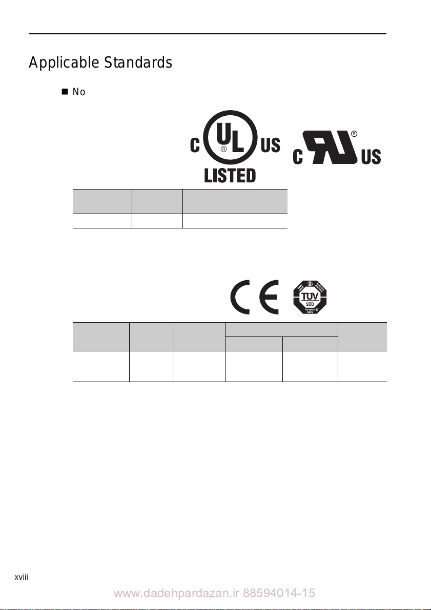
North American Safety Standards (UL)
Model
SERVOPACK SGDV UL508C (E147823)
Underwriters Laboratories Inc.
UL Standards
(UL File No.)
European Standards
Model
SERVOPACK SGDV
Note: Because SERVOPACKs and linear servomotors are built into machines, certification is
required after installation in the user’s product.
Low Voltage
Directive
EN50178
EN61800-5-1
EMC Directive
EMI EMS
EN55011/A2
group 1 class A
EN61
800-3
EN61800-3
EN61000-6
-2
Safety
Standards
EN954-1
IEC61508
to 4
-1
xviii
www.dadehpardazan.ir 88594014-15
Page 20

Contents
About this Manual . . . . . . . . . . . . . . . . . . . . . . . . . . . . . . . . . . . . . . . . . . . . . . . . iii
Safety Precautions . . . . . . . . . . . . . . . . . . . . . . . . . . . . . . . . . . . . . . . . . . . . . . . viii
Warranty . . . . . . . . . . . . . . . . . . . . . . . . . . . . . . . . . . . . . . . . . . . . . . . . . . . . . . . xvi
Applicable Standards . . . . . . . . . . . . . . . . . . . . . . . . . . . . . . . . . . . . . . . . . . . . xviii
1 Overview of Setup . . . . . . . . . . . . . . . . . . . . . . . . . . . . . . . . . . . . . . . . 1-1
2 Installation . . . . . . . . . . . . . . . . . . . . . . . . . . . . . . . . . . . . . . . . . . . . . . 2-1
2.1 Installation Environment and Applicable Standards . . . . . . . . . . . . . . . . . . . . . . . . . . . 2-2
2.1.1 Linear Servomotor Installation Environment . . . . . . . . . . . . . . . . . . . . . . . . . . . . 2-2
2.1.2 SERVOPACK Installation Environment . . . . . . . . . . . . . . . . . . . . . . . . . . . . . . . 2-3
2.1.3 Installation Conditions for Applicable Standards . .
2.2 Linear Servomotor Installation . . . . . . . . . . . . . . . . . . . . . . . . . . . . . . . . . . . . . . . . . . . 2-5
2.2.1 SGLGW and SGLGM Linear Servomotors (Coreless Ty
2.2.2 SGLFW and SGLFM Linear Servomotors (F-type Iron C
2.2.3 SGLTW and SGLTM Linear Servomotors (T-type Iron Core) . . . . . . . . . . . . . . 2-14
2.2.4 SGLC Linear Servomotors (Cylinder Type) . . . . . . . . . . . . . . . . . . . . . . . . . . . 2-21
2.3 Linear Scale Installation and Adjustment . . . . . . . . . . . . . . . . . . . . . . . . . . . . . . . . . . 2-27
2.3.1 Installation Conditions . . . . . . . . . . . . . . . . . . . . . . . . . . . . . . . . . . . . . . . . . . . 2-27
2.3.2 Installation . . . . . . . . . . . . . . . . . . . . . . . . . . . . . . . . . . . . . . . . . . . . . . . . . . . . 2-30
2.3.3 Adjustment . . . . . . . . . . . . . . . . . . . . . . . . . . . . . . . . . . . . . . . . . . . . . . . . . . . . 2-32
2.4 SERVOPACK Installation . . . . . . . . . . . . . . . . . . . . . . . . . . . . . . . . . . . . . . . . . . . . . . 2-33
2.4.1 Orientation . . . . . . . . . . . . . . . . . . . . . . . . . . . . . . . . . . . . . . . . . . . . . . . . . . . . 2-33
2.4.2 Installation Standards . . . . . . . . . . . . . . . . . . . . . . . . . . . . . . . . . . . . . . . . . . . . 2-35
2.5 EMC Installation Conditions . . . . . . . . . . . . . . . . . . . . . . . . . . . . . . . . . . . . . . . . . . . . 2-37
2.5.1 SGDV-05 (Analog Pulse Model) . . . . . . . . . . . . . . . . . . . . . . . . . . . . 2-37
. . . . . . . . . . . . . . . . . . . . . . . . . . . . . . . . . . . 2-45
2.5.2 SGDV-15 (M-II Model)
2.5.3 SGDV-25 (M-III Model) . . . . . . . . . . . . . . . . . . . . . . . . . . . . . . . . . . 2-53
2.5.4 SGDV
2.5.5 Other Precautions . . . . . . . . . . . . . . . . . . . . . . . . . . . . . . . . . . . . . . . . . . . . . . . 2-61
-E5A (Command Option Attachable Type) . . . . . . . . . . . . . . . . 2-61
. . . . . . . . . .
. . . . . . . . . . . . . 2-4
pe) . . . . . . . . . . . . . . . 2-5
ore) . . . . . . . . . . . . . . 2-8
3 Wiring and Connection . . . . . . . . . . . . . . . . . . . . . . . . . . . . . . . . . . . . 3-1
3.1 Precautions for Wiring . . . . . . . . . . . . . . . . . . . . . . . . . . . . . . . . . . . . . . . . . . . . . . . . . 3-3
3.2 System Configuration Diagram . . . . . . . . . . . . . . . . . . . . . . . . . . . . . . . . . . . . . . . . . . 3-4
3.2.1 Connecting to SGDV-05 SERVOPACK (Analog Pulse Model) . . . . . . 3-4
3.2.2 Connecting to SGDV-15 SERVOPACK (M-II Model)
3.2.3 Connecting to SGDV-25 SERVOPACK (M-III
3.2.4 Connecting to SGDV-E5A SERVOPACK
(Command Option Attachable Type) . . . . . . . . . . . . . . . . . . . . . . . . . . . . . . . . 3-16
3.3 Main Circuit Wiring . . . . . . . . . . . . . . . . . . . . . . . . . . . . . . . . . . . . . . . . . . . . . . . . . . . 3-20
3.3.1 Main Circuit Terminals . . . . . . . . . . . . . . . . . . . . . . . . . . . . . . . . . . . . . . . . . . . 3-20
3.3.2 When Using a Standard Power Supply Input
(Single-phase 100 V, Three-phase 200 V, or Three-phase 400 V) . . . . . . . . . . 3-22
3.3.3 When Using the SERVOPACK with a Single-phase 200 V Power Input . . . . . 3-27
3.3.4 When Using the SERVOPACK with a DC Power Input . . . . . . . . . . . . . . . . . . 3-30
. . . . . . . . . . .
Model) . . . . . . . . . . . 3-12
. . 3-8
www.dadehpardazan.ir 88594014-15
xix
Page 21
3.3.5 When Using More Than One SERVOPACK . . . . . . . . . . . . . . . . . . . . . . . . . . . 3-34
3.3.6 General Precautions for Wiring . . . . . . . . . . . . . . . . . . . . . . . . . . . . . . . . . . . . . 3-35
3.3.7 Wiring the Spring Type Main Circuit Terminal Connector . . . . . . . . . . . . . . . . . 3-36
3.4 Connecting Regenerative Resistors . . . . . . . . . . . . . . . . . . . . . . . . . . . . . . . . . . . . . . 3-38
3.4.1 Connecting Regenerative Resistor . . . . . . . . . . . . . . . . . . . . . . . . . . . . . . . . . . 3-38
3.4.2 Setting the Regenerative Resistor Capacity . . . . . . . . . . . . . . . . . . . . . . . . . . . 3-41
3.5 Linear Scale Connections . . . . . . . . . . . . . . . . . . . . . . . . . . . . . . . . . . . . . . . . . . . . . 3-42
3.5.1 Linear Scale Signal (CN2) Names and Functions . . . . . . . . . . . . . . . . . . . . . .3-42
3.5.2 Linear Scale Connection Examples . . . . . . . . . . . . . . . . . . . . . . . . . . . . . . . . . 3-43
4 Safety Function . . . . . . . . . . . . . . . . . . . . . . . . . . . . . . . . . . . . . . . . . . 4-1
4.1 Outline . . . . . . . . . . . . . . . . . . . . . . . . . . . . . . . . . . . . . . . . . . . . . . . . . . . . . . . . . . . . . 4-2
4.2 Hard Wire Base Block (HWBB) Function . . . . . . . . . . . . . . . . . . . . . . . . . . . . . . . . . . . 4-3
4.3 Safety Function Signal (CN8) Names and Functions . . . . . . . . . . . . . . . . . . . . . . . . . . 4-4
4.4 Precautions When Not Using the Safety Function . . . . . . . .
4.5 Connecting a Safety Function Device . . . . . . . . . . . . . . . . . . . . . . . . . . . . . . . . . . . . . 4-5
. . . . . . . . . . . . . . . . . . . . 4-4
5 Trial Operation (Checking Linear Servomoto r Operation) . . . . . . . . . . 5-1
5.1 Outline . . . . . . . . . . . . . . . . . . . . . . . . . . . . . . . . . . . . . . . . . . . . . . . . . . . . . . . . . . . . . 5-2
5.2 Inspection and Checking before Trial Operation . . . . . . . . . . . . . . . . . . .
5.3 Setting the SERVOPACK Parameters . . . . . . . . . . . . . . . . . . . . . . . . . . . . . . . . . . . . .5-4
5.3.1 Setting and Checking the Linear Scale Pitch . . . . . . . . . . . . . . . . . . . . . . . . . . . 5-4
5.3.2 Hall Sensor Selection . . . . . . . . . . . . . . . . . . . . . . . . . . . . . . . . . . . . . . . . . . . . . 5-9
5.3.3 Motor Phase Selection . . . . . . . . . . . . . . . . . . . . . . . . . . . . . . . . . . . . . . . . . . . . 5-9
5.3.4 Setting the Overtravel Signals . . . . . . . . . . . . . . . . . . . . . . . . . . . . . . . . . . . . . 5-11
5.3.5 Setting the Force Limits . . . . . . . . . . . . . . . . . . . . . . . . . . . . . . . . . . . . . . . . . . 5-11
5.4 Execution of Origin Setting (Fn020) . . . . . . . . . . . . . . . . . . . . . . . . . . . . . . . . . . . . . . 5-12
5.5 Polarity Detection . . . . . . . . . . . . . . . . . . . . . . . . . . . . . . . . . . . . . . . . . . . . . . . . . . . . 5-
5.5.1 When U
5.5.2 When Using an Absolute Linear Scale . . . . . . . . . . . . . . . . . . . . . . . . . . . . . . . 5-18
5.5.3 Troubleshooting for Polarity Detection Errors . . . . . . . . . . . . . . . . . . . . . . . . . . 5-21
5.5.4 Related Parameters . . . . . . . . . . . . . . . . . . . . . . . . . . . . . . . . . . . . . . . . . . . . . 5-23
5.6 JOG Operation . . . . . . . . . . . . . . . . . . . . . . . . . . . . . . . . . . . . . . . . . . . . . . . . . . . . . . 5-2
5.6.1 JOG Opera
5.6.2 JOG Operation Using a Digital Operator . . . . . . . . . . . . . . . . . . . . . . . . . . . . . 5-29
5.6.3 JOG Operation Using SigmaWin+ . . . . . . . . . . . . . . . . . . . . . . . . . . . . . . . . . . 5-32
sing an Incremental Linear Scale . . . . . . . . . . . . . . . . . . . . . . . . . . . . . 5-16
tion Using a Panel Operator . . . . . . . . . . . . . . . . . . . . . . . . . . . . . . 5-27
. . . . . . . . . . 5-3
15
4
Revision History
xx
www.dadehpardazan.ir 88594014-15
Page 22
1
Overview of Setup
Overview of Setup
This chapter describes how to set up the -V series of servo drives.
1
1-1
www.dadehpardazan.ir 88594014-15
Page 23
1 Overview of Setup
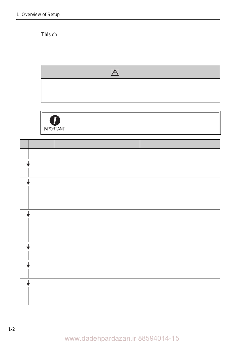
This chapter describes the flow of the setup procedure from installation until a JOG
operation. A panel operator, a digital operator , and SigmaWin+, which is an engineering tool that can be used with a PC, are available to set up a servo drive.
The panel operator is included with the SERVOPACK of analog pulse
the digital operator and SigmaWin+ are sold separately.
• An alarm or warning may be generated if communications are executed with the
host controller during operation using SigmaWin+ or the digital operator.
If an alarm or warning is generated, the process currently being execu
and the system may stop.
Ste
Item Description Reference
p
Installation
1
and mounting
CAUTION
Be sure to read 5.2 Inspection and Checking before Trial Operation.
Install the linear servomotor, linear scale, and SERVOPACK according to the installation conditions.
models, and
ted may be aborted
Chapter 2 Installation
1-2
Wiring and
2
connections
Check points
3
before trial
operation
SERVOPACK
4
’s parameter
setting
5 Origin setting
Polarity
6
detection
JOG
7
operation
Wire and connect the SERVOPACK main circuit, regenerative resistor, linear servomotor, and linear scale.
For a safe and correct trial operation, inspect and check the
following items before trial operation.
• Linear servomotor
• SERVOPACK
• Wiring for main circuit power supply, linear servomotor, and linear scale
Set the following parameters of the SERVOPACK.
• Linear scale pitch (Pn282)
• Hall sensor selection (Pn080.0)
• Motor phase selection (Pn080.1)
• Overtravel signal allocation (Pn50A.3, Pn50B.0)
• Force limits (Pn483, Pn484)
When using an absolute linear scale manufactured by
Mitutoyo Corporation, execute the origin setting (Fn020).
Execute the polarity detection. 5.5 Polarity Detection
Perform a JOG operation for the linear servomotor using:
• Panel operator (for analog pulse models only),
• Digital operator, or
• SigmaWin+
Chapter 3 Wiring and Connection
5.2 Inspection and Checking before Trial Operation
(1) Linear Servomotors
(2) SERVOPACKs
(3) Checking the Main Circuit Power Supply, Lin-
ear Servomotor, and Linear Scale Wirings
5.3 Setting the SERVOPACK Parameters
5.3.1 Setting and Checking the Linear Scale Pitch
5.3.2 Hall Sensor Selection
5.3.3 Motor Phase Selection
5.3.4 Setting the Overtravel Signals
5.3.5 Setting the Force Limits
5.4 Execution of Origin Setting (Fn020)
5.6 JOG Operation
5.6.1 JOG Operation Using a Panel Operator
5.6.2 JOG Operation Using a Digital Operator
5.6.3 JOG Operation Using SigmaWin+
www.dadehpardazan.ir 88594014-15
Page 24

2
Installation
2
Installation
This chapter describes how to install the linear servomotor and the SERVOPACK.
2.1 Installation Environment and Applicable Standards . . . . . . . . . 2-2
2.1.1 Linear Servomotor Installation Environment . . . . . . . . . . . . . . . . .2-2
2.1.2 SERVOPACK Installation Environment . . . . . . . . . . . . . . . . . . . .2-3
2.1.3 Installation Conditions for Applicable Standards . . . . . . . . . . . . . .2-4
2.2 Linear Servomotor Installation . . . . . . . . . . . . . . . . . . . . . . . . . 2-5
2.2.1 SGLGW and SGLGM Linear Servomotors (Coreless Type) . . . . .2-5
2.2.2 SGLFW and SGLFM Linear Servomotors (F-type Iron Core) . . . . 2-8
2.2.3 SGLTW and SGLTM Linear Servomotors (T-type Iron Core) . . .2-14
2.2.4 SGLC Linear Servomotors (Cylinder Type) . . . . . . . . . . . . . . . . 2-21
2.3 Linear Scale Installation and Adjustment . . . . . . . . . . . . . . . . 2-27
2.3.1 Installation Conditions . . . . . . . . . . . . . . . . . . . . . . . . . . . . . . . . .2-27
2.3.2 Installation . . . . . . . . . . . . . . . . . . . . . . . . . . . . . . . . . . . . . . . . . . 2-30
2.3.3 Adjustment . . . . . . . . . . . . . . . . . . . . . . . . . . . . . . . . . . . . . . . . .2-32
2.4 SERVOPACK Installation . . . . . . . . . . . . . . . . . . . . . . . . . . . . 2-33
2.4.1 Orientation . . . . . . . . . . . . . . . . . . . . . . . . . . . . . . . . . . . . . . . . .2-33
2.4.2 Installation Standards . . . . . . . . . . . . . . . . . . . . . . . . . . . . . . . . . 2-35
2.5 EMC Installation Conditions . . . . . . . . . . . . . . . . . . . . . . . . . . 2-37
2.5.1 SGDV-05 (Analog Pulse Model) . . . . . . . . . . . . . . . . .2-37
2.5.2 SGDV-15 (M-II Model) . . . . . . . . . . . . . . . . . . . . . . . .2-45
2.5.3 SGDV-25 (M-III Model) . . . . . . . . . . . . . . . . . . . . . . . .2-53
2.5.4 SGDV-E5A (Command Option Attachable Type) . . . . . . 2-61
2.5.5 Other Precautions . . . . . . . . . . . . . . . . . . . . . . . . . . . . . . . . . . . .2-61
2-1
www.dadehpardazan.ir 88594014-15
Page 25
2 Installation
Vertical
Vertical
Side to side
axis
direction
horizontal
Fron to back
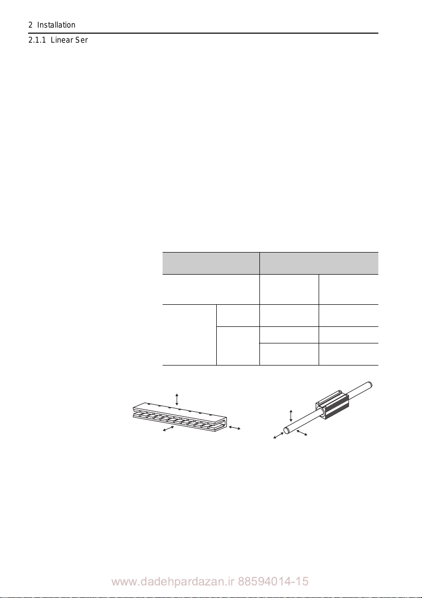
Impact applied to SGLGW,
SGLFW, and SGLTW models
Impact applied to SGLC model
2.1.1 Linear Servomotor Installation Environment
2.1 Installation Environment and Applicable Standards
The installation environment and the applicable standards for linear servomotors and
SERVOPACKs are described in thi s section.
2.1.1 Linear Servomotor Installation Environment
Ambient temperature: 0C to 40C Ambient humidity: 20% to 80% RH or less (with no condensation) Altitude: 1, 000 m or less Vibration resistance: The linear servomotor will withstand the
following
directions: vertical, side to side, and front to
back.
vibration acceleration in three
2-2
Servomotor Model
SGLGW
SGLFW
SGLTW
Moving
Coil
SGLC
www.dadehpardazan.ir 88594014-15
Magnetic
Way
three directions
three directions
axis direction
vertical, hori-
zontal
Vibration Acceleration at
Flange
49 m/s
24
24.5 m/s
4.9 m/s
.5 m/s
2
2
2
2
Page 26
2.1 Installation Environment and Applicable Standards
2
Installation
Impact Resistance: The linear servomotor will with stand the following
impact acceleration.
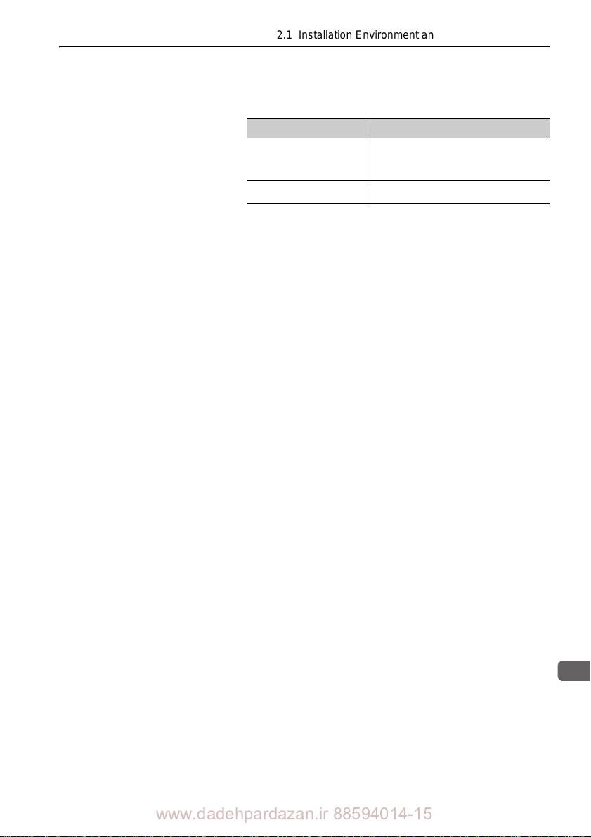
Servomotor model Impact acceleration
SGLGW
SGLFW
SGLTW
SGLC
196 m/s
98 m/s
2
twice
2
twice
Installation site: An environ
ment that satisfies the following conditions
• Indoors and free of corrosive or explosive gases
• Well-ventilated and free of dust and mois ture
• Facilitates inspection and cleaning
• Free of high magnetic field
2.1.2 SERVOPACK Installation Environment
Surrounding air temperature: 0C to 55C Ambient humidity: 90% RH or less (with no condensation) Altitude: 1,000 m or less
Vibration resistance: 4.9 m/s
Shock resistance: 19.6 m/s Installation Precautions
• Mounting in a Control Panel
To pre vent the tempe rature around the SERVOPACK from exceeding 55C, take i
account the size of the control panel, the layout of the SER VOPACK, and the cooling
method. For details, refer to 2.4 SERVOPACK Installation.
2
2
nto
• Mounting Near a He ating Unit
To prevent the temperature around the SERVOPACK from exceeding 55C, suppress
radian
t heat from the heating unit and temperature rise due to convection.
• Mounting Near a Vibration Source
To prevent vibration from being transmitted to the SERVOPACK, insta ll a vibration
isolator underneath the SERVOPACK.
www.dadehpardazan.ir 88594014-15
2-3
Page 27

2 Installation
2.1.3 Installation Conditions for Applicable Standards
• Mounting to a Location Expose d to Corrosive Gas
Ta ke measures to prevent exposure to corrosive gas. Corrosive gases will not immediately affect the SERVOP AC K, but will eventually cause electronic components and
contactor
-related devices to malfunction.
• Other Locations
Do not mount the SERVOPACK in locations subject to high temperatures, high
humidity, dripping water, cutting oil, dust, iron filings, or radiation.
Note: When storing the SERVOPACK with the power OFF, store it in an environment with the
following temperature and humidity:
•-20C to
+85C, 90% RH
or less. (with no condensation)
2.1.3 Installation Conditions for Applicable Standards
Applicable
Standards
Operating
Conditions
Installation
Conditions
UL508C
EN50178, EN55011/A2 group1 classA, EN61000-6-2, EN61800-3,
1800-5-1, EN954-1, IEC61508-1 to 4
EN6
Overvoltage Category: III
Pollution degree: 2
Protection class: IP10
UL Standard and Low Voltage Directive:
Satisfy the conditions outlined in
Precautions (TOBP C710800 10)
EMC Directive:
Certification is required after installation in the user’s
conditions outlined in 2.5 EMC Installation Conditions of this manual.
-V Series AC SERVOPACK SGDV Safety
machine under the
2-4
www.dadehpardazan.ir 88594014-15
Page 28
2
Installation
2.2 Linear Servomotor Installation
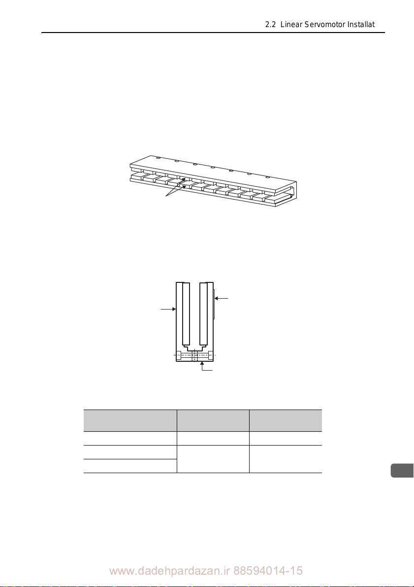
Magnets
2.2 Linear Servomotor Installation
2.2.1 SGLGW and SGLGM Line
(1) Magnetic Way Installation
The SGLGM magnetic way comprises a U-channel steel track with opposing magnets attached to the inner faces. Make sure that no foreign particles (magnetic
objects) are caught between the
Use the following procedure to install SGLGM m
magnets when installing the magnetic way.
1. After checking the magnetic way’s two mounting reference surfaces,
place the magnetic way on the reference surface of the machine base,
making sure that hands are kept clear.
Mounting
reference
surface
ar Servomotors (Coreless Type)
agnetic ways.
Nameplate
Mounting reference surface
2. Place the magnetic way on the reference surface of the machine and
secure it with bolts.
Magnetic Way Model
SGLGM30 M4 360 to 500
40
60
Note: Use hexagonal socket head bolts (tensile strength Class 10.9).
Bolt size
M5 720 to 1010
Tightening torque
(Ncm)
www.dadehpardazan.ir 88594014-15
2-5
Page 29
2 Installation
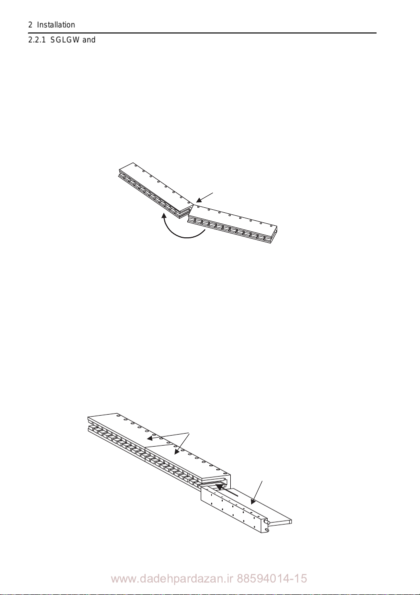
First magnetic way
Second magnetic way
Align the angles
Rotate the magnetic way position.
2.2.1 SGLGW and SGLGM Linear Servomotors (Coreless Type)
3. When joining magnetic ways together, place the second magnetic way
temporarily in line with and at least 30 mm apart from the first magnetic
way.
Next, after aligning the angles of bolt sockets on the magnetic way’s
connecting surfaces, move the second magnetic way to join the first
magnetic way. Connect the second and first magnetic ways together.
And, after confirming the mounting position, secure the second magnetic
way using bolts. Make sure that fingers do not get jammed due to the
magnetic attraction between magnetic ways.
(2) Moving Coil Installation
The SGLGW moving coil is constructed of an aluminum base and a resin-coated coil
winding section. Handle the moving coil with care and do not subject the coil winding section to shock. Doing so may cause injury or damage to the moving coil.
Use the following procedure to install the SGLGW moving coil.
1. Insert the coil winding section of the moving coil between the magnets of
2-6
the magnetic way that has already been installed. Next, install the
moving coil on the movable table supported by the linear guide. Install
the moving coil on the movable table supported by the linear guide.
Make sure that the air gap between the moving coil’s coil winding
section and magnetic way’s magnets is the specified distance.
Magnetic way
Coil winding section
Moving coil
www.dadehpardazan.ir 88594014-15
Page 30
2.2 Linear Servomotor Installation
2
Installation
Air gap
G1
Air gap
G1
Moving coil
Magnetic way
Air gap
G2
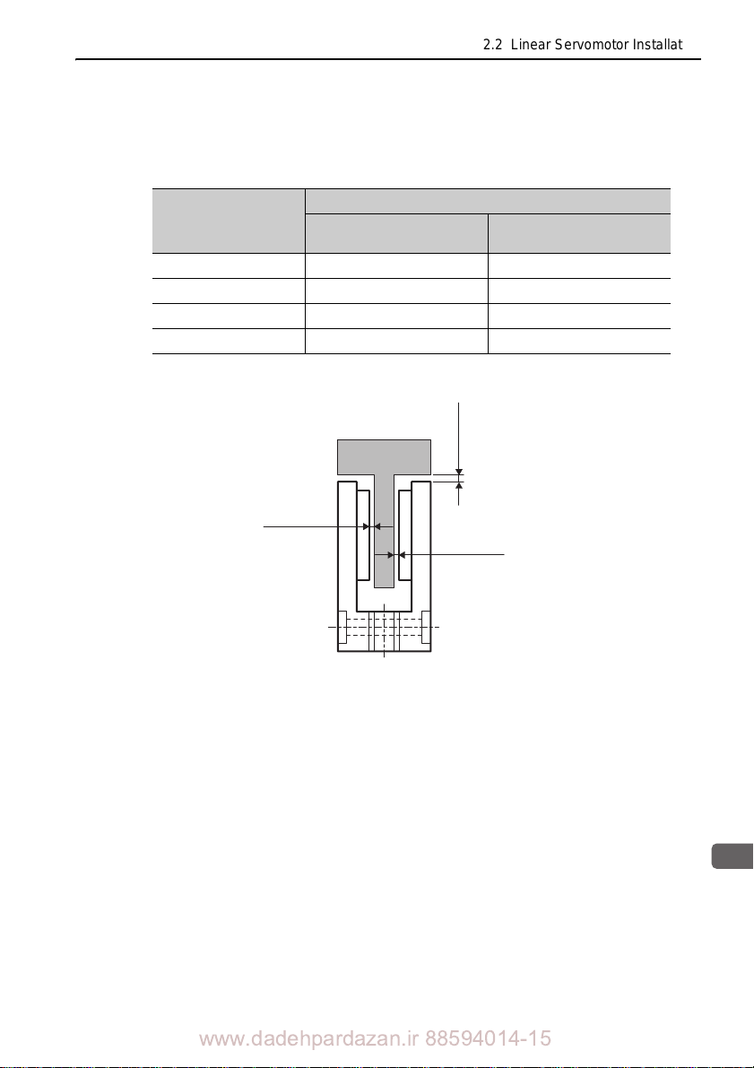
The relationship between the dimensions and positioning between the moving coil’s
coil winding section and magnetic ways’s magnets is shown here. Maintain the fol
lowing air gaps when installing. Make sure that the moving coil
and magnetic way do
-
not interfere with each other during the stroke.
Moving Coil Model
SGLGW-
30A050 0.85 0.3 1 0.
30A080 0.95 0.3 1 0.
40A 0.8 0.3 1 0.
60A 0.8 0.3 1 0.
Air gap
Dimensions in mm
G1
Air gap
G2
3
3
3
3
2. Move the moving coil back and forth several times over the magnetic
way from end to end, making sure that the moving coil and magnetic
way are not touching each other and that no foreign objects such as
magnetic particles are present.
www.dadehpardazan.ir 88594014-15
2-7
Page 31
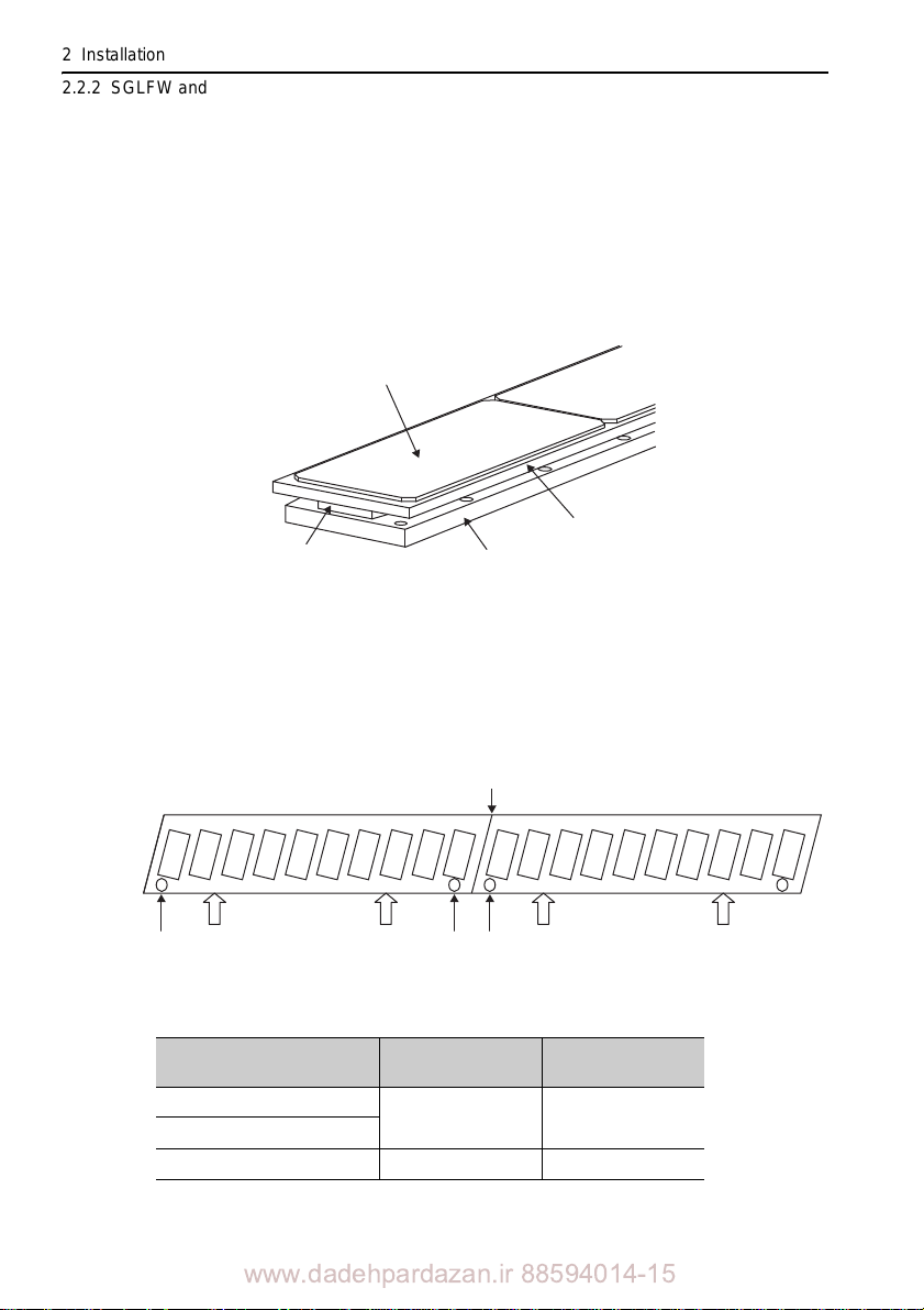
2 Installation
Dummy plate for reducing magnetic force
Magnetic way yoke
Cardboard sheet
Magnet
Magnetic way connection
Reference surface
Reference mark
Reference marks
2.2.2 SGLFW and SGLFM Linear Servomotors (F-type Iron Core)
2.2.2 SGLFW and SGLFM Linear Servomotors (F-type Iron Core)
(1) Magnetic Way Installation
The SGLFM magnetic way is packed with a cardboard sheet covering the magnetic
surface, above which is a thin, rectangular steel plate.
The steel plate is a dummy plate used to re duce the influence of magnetic force on
the
surrounding environment. When removing the plate, make sure that fingers are kept
clear and that the magnet and magnet protection cover are not damaged.
Use the following procedure to inst
all the SGLFM magnetic way.
1. Remove the dummy plate used to reduce magnetic force and the
cardboard sheet from the magnetic way’s magnetic surface.
2. Align the reference marks (approx. 4-mm dia. indentations) on the side
of the magnetic way with the reference surface of the machine base,
keeping fingers clear to prevent injury.
3. While placing the magnetic way on the machine base reference surface,
secure it with bolts.
Magnetic Way Model
SGLFM-
2-8
20
35
50 M5 720 to 1010
Note: Use hexagonal socket head bolts (tensile strength Class 10.9).
www.dadehpardazan.ir 88594014-15
Bolt size
Tightening torque
(Ncm)
M4 360 to 500
Page 32
2.2 Linear Servomotor Installation
2
Installation
Magnet
Magnetic
way yoke
K
First magnetic way
Second magnetic way
Magnetic attraction
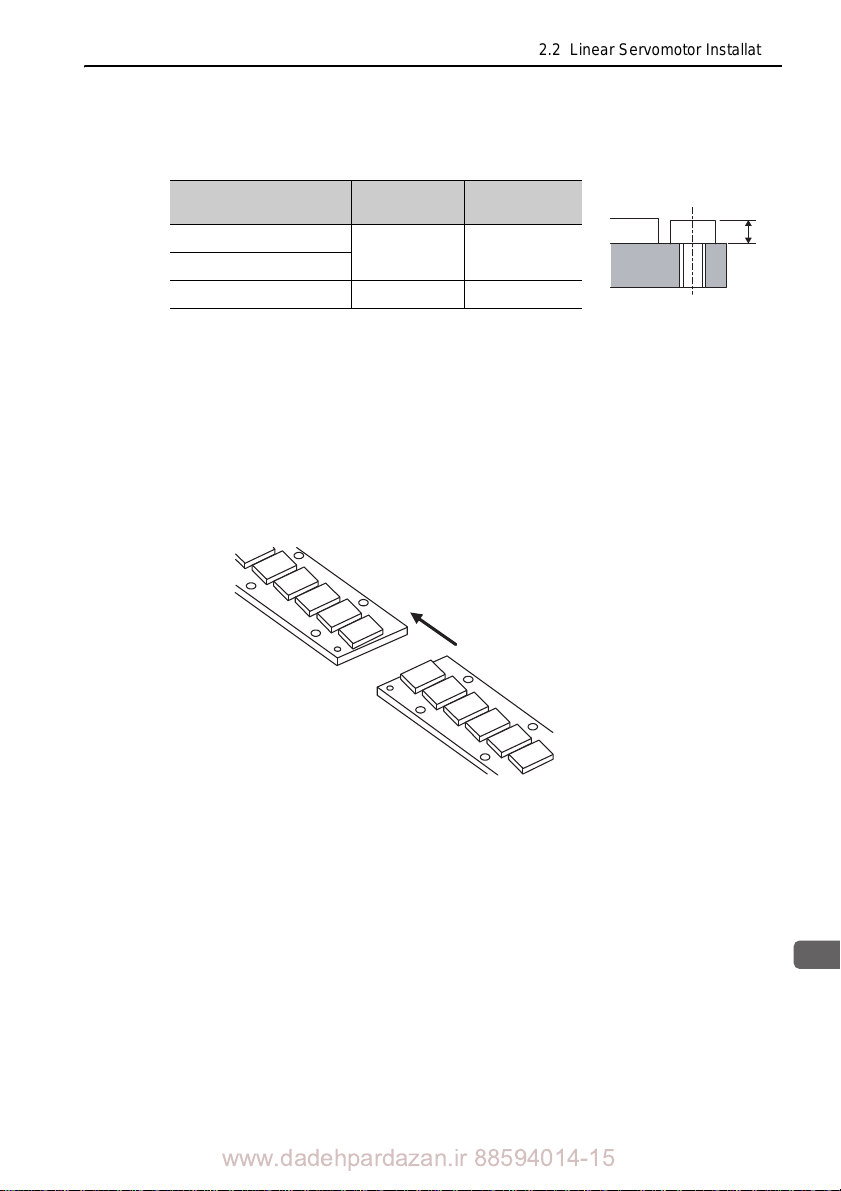
Note: The magnetic way’s magnets exert strong magnetic attraction. Make sure that steel bolts
or wrenches are kept away from the magnets. Always use bolts with a head height
according to the dimensions shown in the following table.
Magnet Way Model
SGLFM20
35
50 M5 5.2 max.
Bolt size
M4 4.2 max.
Head height K
in mm
4. When joining magnetic ways together, place the second magnetic way
temporarily in line with and at least 30 mm apart from the first magnetic
way. Next, match the direction of the magnetic ways (using the
indentations as reference (approx. dia. 4 mm)). (Refer to the diagram in
step 2.) Next, while holding the magnetic ways down so that they are not
raised, push the second magnetic way against the first magnetic way
and secure it with bolts. The magnetic ways may snap together due to
the strong magnetism. Keep fingers clear to avoid injury.
Note: To ensure your safety , install the moving coil before installing the second and subsequent
magnetic ways. For details, refer to (2) Moving Coil Installation.
www.dadehpardazan.ir 88594014-15
2-9
Page 33
2 Installation
Magnetic
way
Moving coil
Movable table
2.2.2 SGLFW and SGLFM Linear Servomotors (F-type Iron Core)
(2) Moving Coil Installation
The SGLFW moving coil is constructed of an aluminum or steel base and iron core,
with a resin-coated coil winding section. Make sure that the coil winding section is
not subjected to shock during installation. Shock may cause injury or damage to the
moving coil.
Use the following procedure to install the SGLFW moving coil.
1. Install the moving coil on the movable table supported by the linear
guide in line with the already installed magnetic way.
Make sure that the air gaps between the moving coil and magnetic way’s
magnets is the specified distance.
Maintain the following air gaps when installing. Make sure that the
moving coil and
stroke.
magnetic way do not interfere with each other during the
2-10
Moving Coil Model
SGLFW-
20AA
35A
A 21 0.2
50A
The value in parentheses is the dimension when the magnet protection cover is used.
B 58 0.1 25.8
H P
45 0.
Dimensions in mm
1
22 0.2
0.2
Air gap
0.3
1
0.8
(
G
)*
www.dadehpardazan.ir 88594014-15
Page 34
2.2 Linear Servomotor Installation
2
Installation
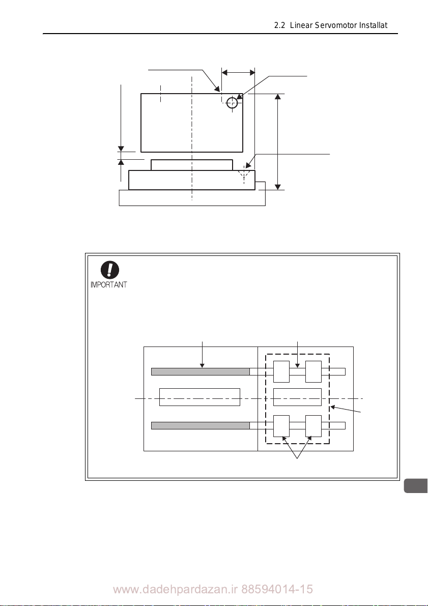
Magnetic way
Actual linear guide Dummy linear guide
Movable
table
Block
Moving coil
Installation tap
Moving coil
Air gap G
Magnetic way
Linear servomotor side view
(Viewed from the side where the cable
extends from the moving coil)
P
Cable
H
Reference mark
When two or more magnetic ways are used, first install one of the
magnetic ways, and then install the moving coil in the available space.
If using only one magnetic way
, and the linear guide is not long
enough extend up to the position needed to temporarily place the
moving coil in line with the magnetic way, mount a dummy linear guide
to the actual linear guide as shown in the figure below.
• Mounting a dummy linear guide
www.dadehpardazan.ir 88594014-15
2-11
Page 35
2 Installation
Nonmagnetic
sheet
Slowly move the
moving coil.
2.2.2 SGLFW and SGLFM Linear Servomotors (F-type Iron Core)
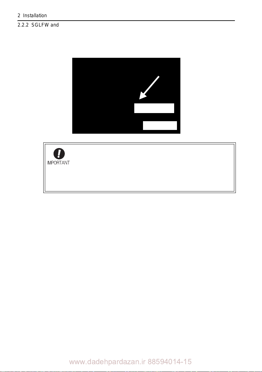
2. Insert a thin nonmagnetic (preferably resin) sheet (approximately 0.5-
mm thick) in the air gap between the moving coil and magnetic way.
Then, and move the moving coil toward the magnetic way.
Always be aware of the strong magnetism of the magnetic way and
keep fingers and tools at a safe distance, especially when the moving
coil is near the magnetic way. The moving coil will be strongly
attracted to the magnetic way. When the specified dimensions of the
air gaps between the moving coil and the magnetic way are secured,
it is not necessary to insert nonmagnetic sheets into the air gaps. (see
the table of dimensions in step 1.)
2-12
3. Move the moving coil back and forth several times over the magnetic
way from end to end, making sure that the moving coil is not touching
the magnetic way and that no foreign objects (such as magnetic
particles) are present. Use a nonmagnetic (brass or stainless steel) gap
gauge to check that the air gap between the moving coil and the
magnetic way is even.
(3) Magnetic Attraction
The linear servomotor is constructed of an opposing moving coil and magnetic way.
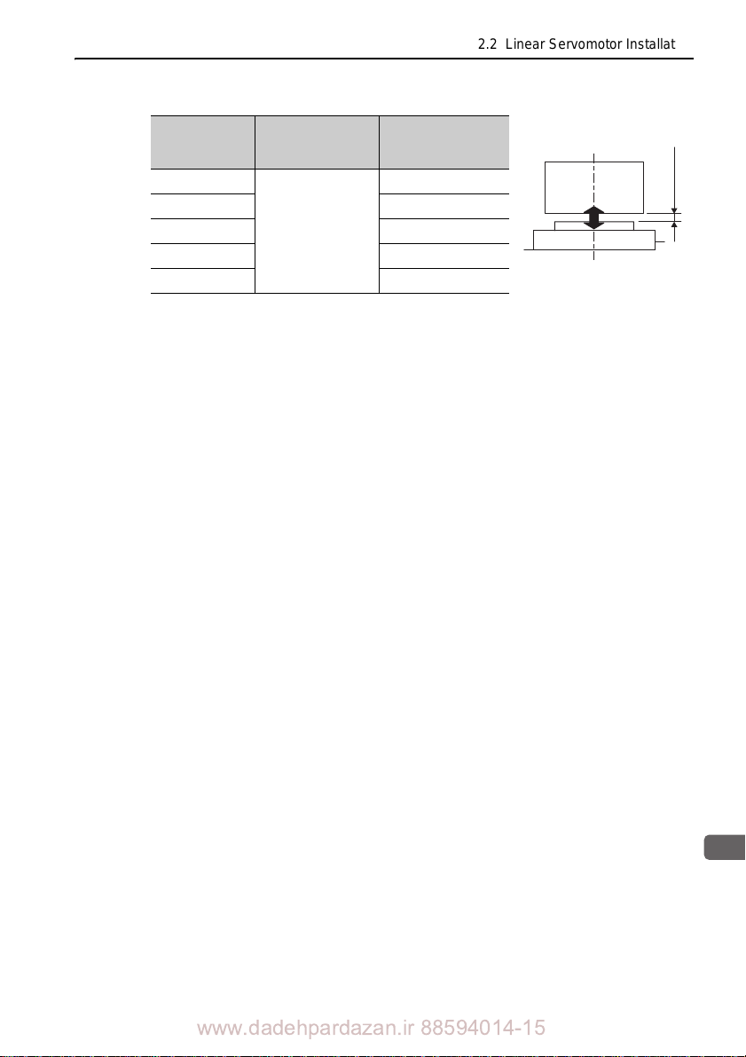
Therefore, the moving coil is subjected to magnetic attra ction as shown in the following table (calculated value). Consider the magnetic attraction when design ing the sys tem.
www.dadehpardazan.ir 88594014-15
Page 36
2.2 Linear Servomotor Installation
2
Installation
Air gap
G
Magnetic
attraction
F
Moving Coil
Model
SGLFW-
20A090A
Air gap G
in mm
1
Magnetic attraction
F
410
2
20A120A 600
35A120A 1100
0.7
35A230A 2100
50A200B 2700
Indicates an air gap value of -0.3 mm relative to the design value.
Indicates the magnetic attraction fo
r the maximum force.
2-13
www.dadehpardazan.ir 88594014-15
Page 37
2 Installation
Spacer
Caution!
Magnetic force!
2.2.3 SGLTW and SGLTM Linear Servomotors (T-type Iron Core)
2.2.3 SGLTW and SGLTM Linear Servomotors (T-type Iron Core)
(1) Magnetic Way Installation
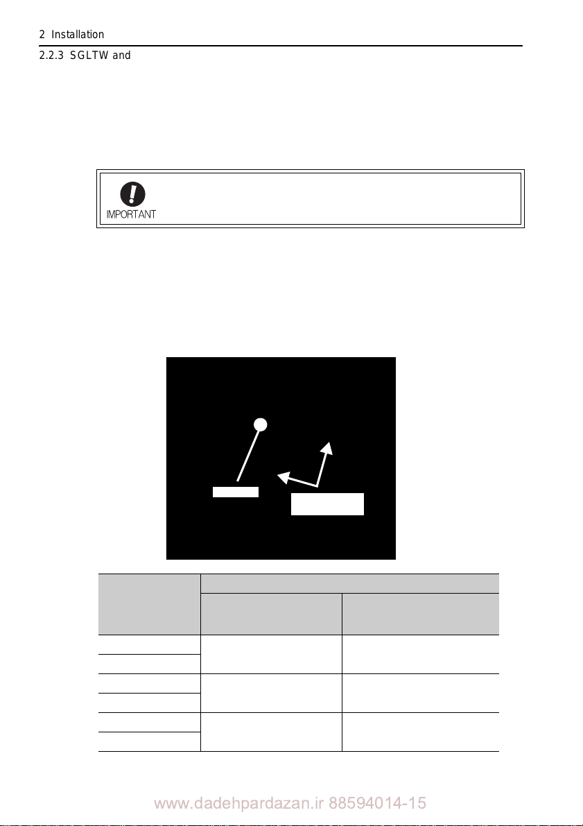
The SGLTM magnetic way is packed with two yokes securely positioned with an
aluminum spacer.
Do not remove the spacers until the magnetic way is temporarily fixed
to the system.
Use the following procedure to install the SGLTM magnetic way.
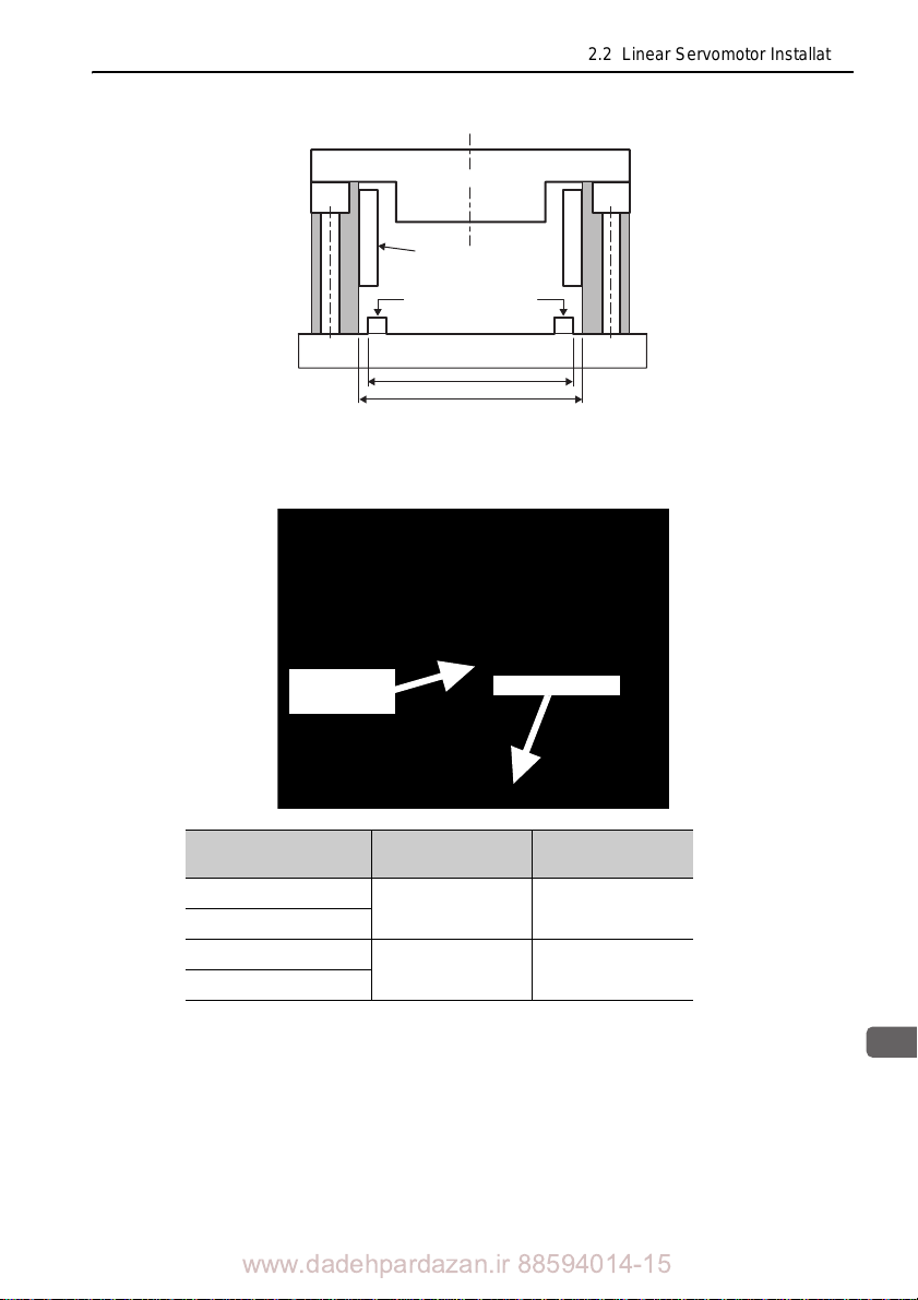
1. With the spacers attached, place the magnetic way on both positioning
steps. Make sure that the machine and magnetic way are not scratched
or dented when positioning the magnetic way. Set the dimensions of
these positioning steps to match the W2 dimensions in the following
table.
2-14
Magnetic Way
Model SGLTM-
20
35
40
80
35H
50H
www.dadehpardazan.ir 88594014-15
Dimensions in mm
W1
(Dimensions at shipment)
71.5 1
113 1 111.8 0.
91.5 1
(Recommended machine
W2
base value)
70
0.15
15
0.15
90
Page 38
2.2 Linear Servomotor Installation
2
Installation
Hold down the
magnetic way
yoke
Positioning step
spacer
Magnet
Positioning steps
W2
W1
2. Insert the mounting bolts into one of the two magnetic way yokes and
tighten lightly by hand. Next, while firmly holding down the magnetic way
yoke onto the positioning step, tighten the bolts firmly.
Magnetic Way Model
SGLTM20
35
35H
50H
Note: The following conditions apply to these values.
• Machine material: Steel
• Hexagonal socket head bolts (tensile stre
Bolt size
M6 1220 to 1710
M6 1220 to 1710
Tightening torque
ng
www.dadehpardazan.ir 88594014-15
(Ncm)
th Class 10.9)
2-15
Page 39
2 Installation
Magnetic attraction
2.2.3 SGLTW and SGLTM Linear Servomotors (T-type Iron Core)
3. After removing the spacer fixing bolts from the side of the already
installed magnetic way yoke, firmly hold the other magnetic way yoke
onto the positioning step, while firmly tightening the bolts. Make sure
that the magnetic way yokes do not slip into the path of the moving coil.
4. Unscrew the rest of the spacer fixing bolts to remove the spacer. Check
where the spacer was fixed to see if there are any mounting holes. If
there are, insert bolts into them and tighten the bolts.
5. When joining magnetic ways together, place the second magnetic way
temporarily in line with and at least 30 mm apart from the first magnetic
way. Next, while pushing the second magnetic way against the first
magnetic way, secure it with bolts. Keep fingers clear to prevent them
from being jammed between the magnetic ways due to the magnetic
attraction pulling the magnetic ways together.
Follow the same procedure as in steps 1 to 4 to install subsequent
magnetic ways.
2-16
Note: To ensure your safety, install the moving coil before installing second and subsequent
magnetic ways. For details, refer to (2) Moving Coil Installation.
www.dadehpardazan.ir 88594014-15
Page 40
2.2 Linear Servomotor Installation
2
Installation
Moving coil
Magnetic way
(2) Moving Coil Installation
The SGLTW moving coil is constructed of an aluminum or steel base and iron core,
with a resin-coated coil winding section. Make sure that the coil winding section is
not subjected to shock during installation. Shock may damage the moving coil.
Use the following procedure to install the SGLTW moving coil.
1. Install the moving coil on the movable table supported by the linear
guide in line with the already installed magnetic way.
Make sure that the air gaps between the moving coil and magnetic way’s
magnets
is the specified distance.
Maintain the following air gaps when installing. Make sure that the
moving coil an
d magnetic way do not interfere with each other during the
stroke.
Moving Coil
Model
SGLTW-
20AA 55 0.3
35AA 70 0.3
35AH 70
50AH 85 0.3 19.1 0.1
The value in parentheses is the dimensions when the magnet protection cover is used.
H A
0.3 15 0.
Dimensions in mm
15 0.1
1
Air gap
G1,G2
1 0.3
(0.8
)
1 0.3
)
(0.8
*
www.dadehpardazan.ir 88594014-15
2-17
Page 41
2 Installation
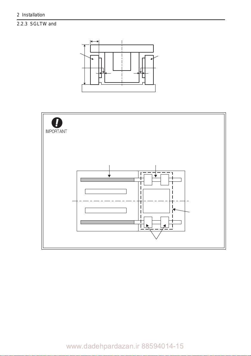
A
Magnetic
way
Magnetic
way
Air gap
G1
Air gap
G2
Moving coil
Linear servomotor side view
(Viewed from the side where the cable
extends from the coil assembly)
H
2.2.3 SGLTW and SGLTM Linear Servomotors (T-type Iron Core)
When two or more magnetic ways are used, first install one of the
magnetic ways, and then install the moving coil in the available space.
If using only one magnetic way, and the
enough extend up to the position needed to temporarily place the
moving coil in line with the magnetic way, mount a dummy linear guide
to the actual linear guide as shown in the figure below.
• Mounting a dummy linear guide
Actual linear guide Dummy linear guide
linear guide is not long
2-18
www.dadehpardazan.ir 88594014-15
Magnetic way
Magnetic way
Moving coil
Movable table
Block
Page 42
2.2 Linear Servomotor Installation
2
Installation
Nonmagnetic sheet
Slowly move the
moving coil
Movable table
2. Insert a thin nonmagnetic (preferably resin) sheet (approximately 0.5-
mm thick) in the air gap between the moving coil and magnetic way.
Then, move the moving coil slowly toward the magnetic way.
Always be aware of the strong magnetism of the magnetic way and
keep fingers and tools at a safe distance, especially when the moving
coil is near the magnetic way. The moving coil will be strongly
attracted to the magnetic way. When the specified dimensions of the
air gaps between the moving coil and the magnetic way are secured,
it is not necessary to insert nonmagnetic sheets into the air gaps. (see
the table of dimensions in step 1.)
3. Move the moving coil back and forth several times over the magnetic
way from end to end, making sure that the moving coil is not touching
the magnetic way and that no foreign objects (such as magnetic
particles) are present. Use a nonmagnetic (brass or stainless steel) gap
gauge to check that the air gap between the moving coil and magnetic
way is even (tolerance: 0.3 mm).
2-19
www.dadehpardazan.ir 88594014-15
Page 43
2 Installation
2.2.3 SGLTW and SGLTM Linear Servomotors (T-type Iron Core)
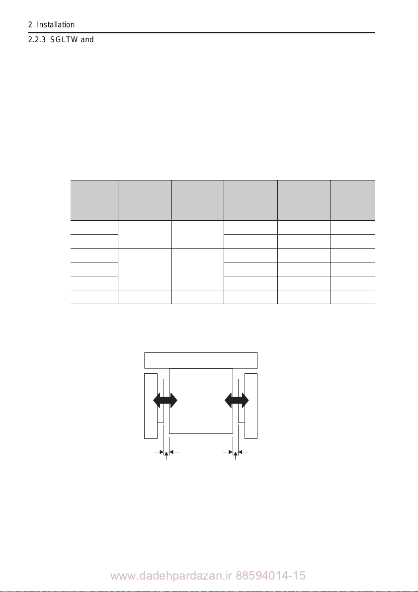
(3) Magnetic Attraction
The linear servomotor is constructed of an opposing moving coil and magnetic way.
So, the magnetic attraction is offset when the air gaps between the moving coils and
the magnetic way are even.
However, achieving an even air gap is diffic
vomotor itself and the customer’s machi n e, and be
to the accuracy of the linear ser-
ult due
cause of errors in the assembly of
the linear servomotor at installation. Consider the magnetic attraction values (calculated values) shown in the following table when designing the system.
Moving Coil
Model
SGLTW-
20A170A
20A320A 1510 2040 530
Air gap
1
G1
in mm
1.3 0.7
Air gap
1
G2
in mm
35A170A
35A170H 1330 1800 470
1.3 0.7
Magnetic
attraction
2
F1
(N)
760 1030 270
1330 1800 470
35A320A 2650 3570 920
50A170H 1.3 0.7 1900 2600 700
Indicates an air gap when one side is +0.3 mm and the other side 0.3 mm relative to the
design values.
Indicates the magnetic attraction at maximum force.
Moving coil
Magnetic
attraction
F1
Magnetic
attraction
F2
Magnetic
attraction
2
F2
(N)
Attraction
difference
F
(N)
2-20
Magnetic way
Air gap
G1
Magnetic way
Air gap
G2
www.dadehpardazan.ir 88594014-15
Page 44
2.2 Linear Servomotor Installation
2
Installation
Magnetic way, stainless
steel pipe
Nameplate
Moving coil, aluminum frame
(In this figure, cables are omitted.)
Resin section for the moving coil
Outlet for the cable
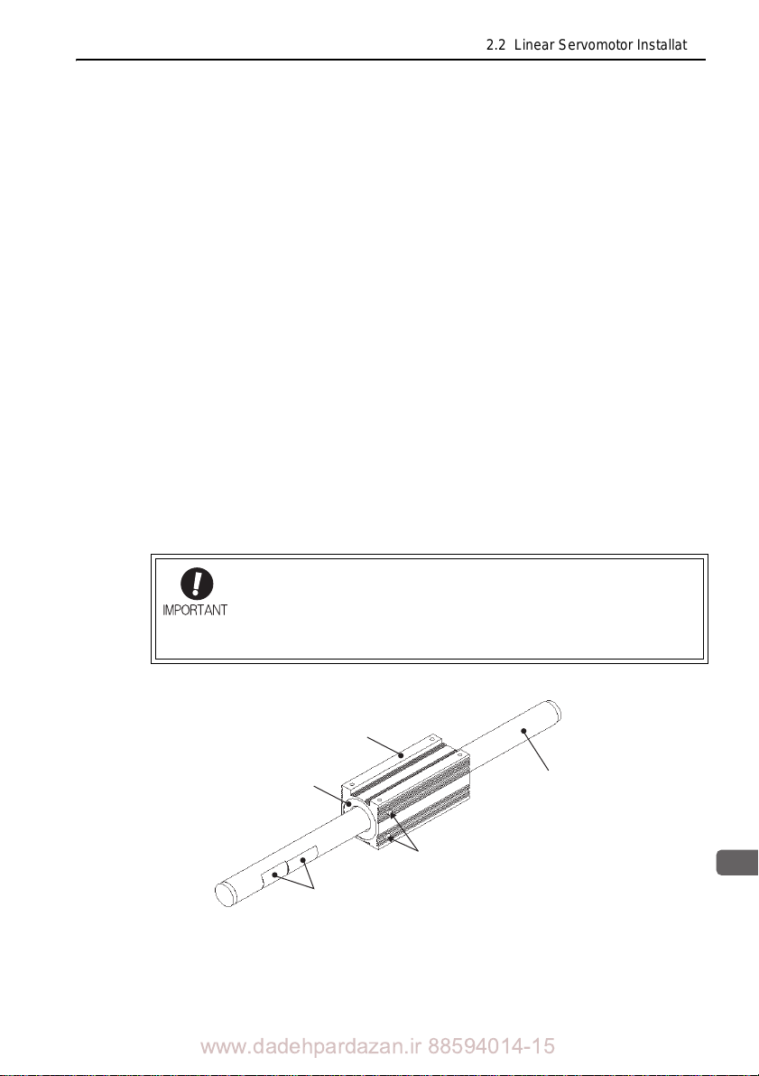
2.2.4 SGLC Linear Servomotors (Cylinder Type)
(1) Components
The magnetic way consists of the following parts.
• Pipe (made of stainless steel)
• Magnet in the pipe
Make sure not to get your fingers or other objects caught in the magnetic way
se a strong magnetic attraction is generated in the area surrounding the mag-
becau
netic way.
The moving coil consists of the following parts.
Outer frame (made of aluminum)
•
• Resin section for protecting winding
• Cables for motor main circuit or hall sensor
If force is applied to the resin section, injury or
(2) State of Delivery
This product is delivered with a resin piece inserted between the moving coil and the
magnetic way to protect the winding.
damage to the product may result.
For safety reasons, mount the linear servomotors onto a machine with
the moving coil attached to the magnetic way of the linear servomotor.
If the moving coil must be separated from the magnetic way for any
reason, make sure not to get your fingers or other objects caught in
the magnetic way. A strong magnetic attraction is generated.
www.dadehpardazan.ir 88594014-15
2-21
Page 45
2 Installation
0.2 mm or less
0.2 mm or less
Moving coil
Magnetic way
Fix these positions with bolts.
Parts for supporting the magnetic way
(To be provided by the customer)
Note: The shape shown in the
figure is an example.
Install the product so that the nameplate can be read.
In particular, be careful so that the caution about the
magnetic attraction is easily visible.
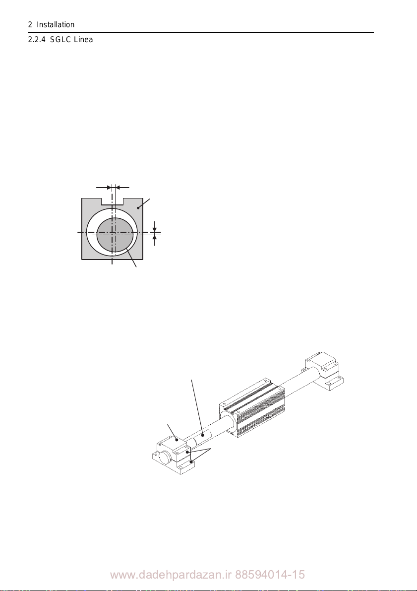
2.2.4 SGLC Linear Servomotors (Cylinder Type)
(3) Installation Procedure
1. Install the linear guide and the parts for supporting the magnetic way on
the machine side.
• Set the positions of the parts for supporting the
the outer dimension of the magnetic way referring to Table 2.1.
• In most case, the length of the magnetic way is regarded as the side where the
nameplate 0.1 mm thick indicating the ratings and a caution about the magnetic attraction.
• Construct the machine so that the difference between the centers of the crosssectiona
l surfaces of the magnetic way and the moving coil should be within
0.2 mm. Refer to the following diagram.
2. Take the product out of the package with the moving coil and the
magnetic way being combined (same as the state when the product is
delivered).
3. Insert both ends of the magnetic way in the supporting parts, and fix
them with bolts.
• Refer to Table 2.1 Dimensions of the Magnetic Way (Selected models
magnetic way after checking
only).
2-22
www.dadehpardazan.ir 88594014-15
Page 46
2.2 Linear Servomotor Installation
2
Installation
Reference side
(mounting side)
L5
L4
L2 L3
L1
L6 (L7)
(L2)
L4
Nameplate
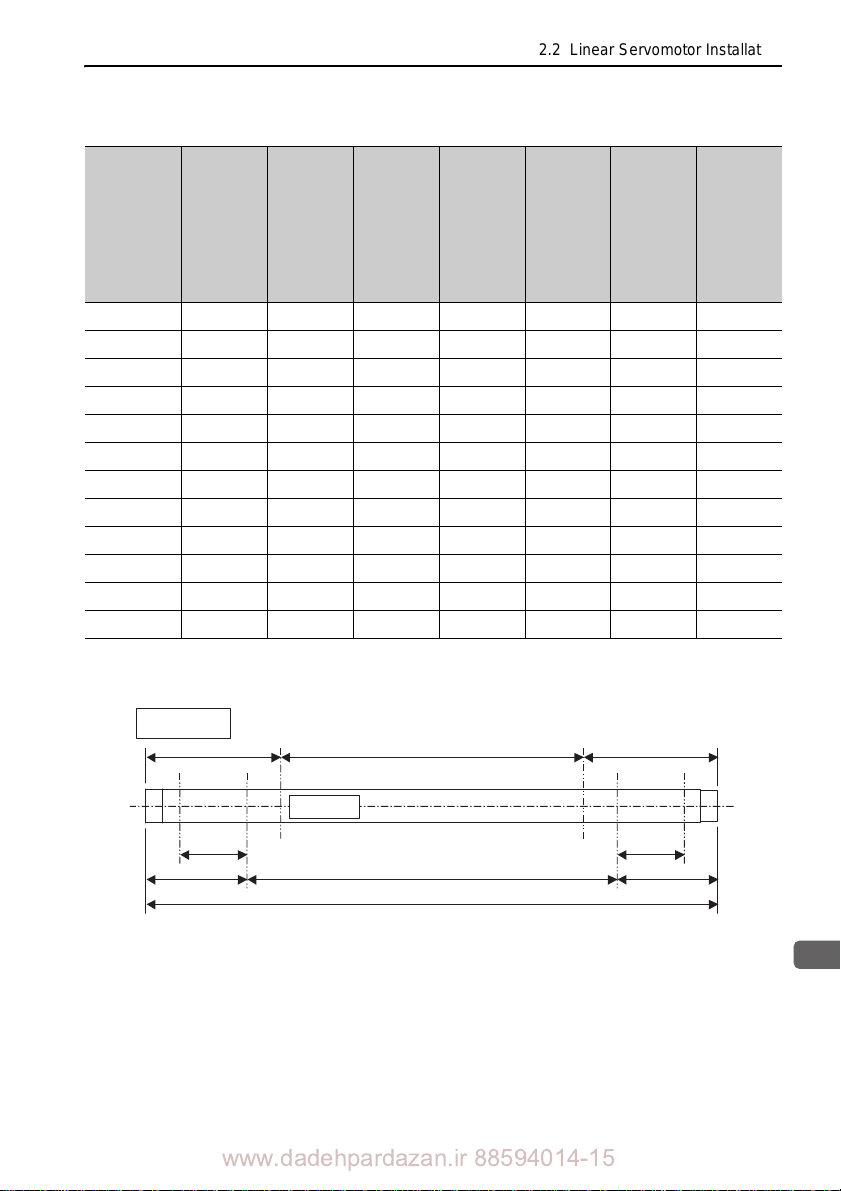
Table 2.1 Dimensions of the Magnetic Way (Selected models only)
Total
Magnetic
Way
Model
SGLCM-
Length
of Mag-
netic
Way L1
(mm)
16300A 300 1.6 30 240 25 37.5 0.3 225 1.2 37.5
D
Position
of
Support
Section
L2 (mm)
Driving
Range
of Coil
Assem-
bly
L3 (mm)
Length
of Sup-
port
Section
L4 (mm)
Range
outside
the
Guaran-
teed
Force
L5 (mm)
*
Range
within
the
Guaran-
teed
Forc
L6 (mm)
Range
outside
the
Guaran-
teed
e
Force
L
7 (mm)
D16510A 510 2.5 45 420 40 52.5 0.3 405 2.1 52.5
D16750A 750 3.0 45 660 40 52.5 0.3 645 2.5 52.5
D20350A 350 1.6 35 280 30 45 0.3 260 1.2 45
D20590A 590 2.5 50 490 45 60 0.3 470 2.1 60
D20870A 870 3.0 50 770 45 60 0.3 750 2.5 60
D25450A 450 1.6 45 360 37 57.5 0.3 335 1.2 57.5
D25750A 750 2.5 60 630 52 72.5 0.3 605 2.1 72.5
D251110A 1110 3.0 60 990 52 72.5 0.3 965 2.5 72.5
D32600A 600 1.6
60 480 52 75 0.3 450 1.2 75
D321020A 1020 2.5 90 840 82 105 0.3 810 2.1 105
D321500A 1500 3.0 90 1320 82 105 0.3 1290 2.5 105
If a part of the moving coil is located within this range
, predetermined characteristics cannot be satisfied.
*
www.dadehpardazan.ir 88594014-15
2-23
Page 47
2 Installation
2.2.4 SGLC Linear Servomotors (Cylinder Type)
4. After mounting the movable table provided by the customer on the linear
guide, transfer the movable table onto the moving coil and secure them
with bolts.
• Carefully lay wiring so that no cables are caught, and fix them to the movable
table.
• For the recommended tightening torque of the bolts for fixing the moving coil,
refer to Table 2.2 Moving Coil and Recommended Tightening Torque.
Table 2.2 Moving Coil and Recommended Tightening Torque
Moving Coil
Model
SGLCWD16 M3 100
D20 M4 220
D25 M5 450
D32 M6 760
Note: Use hexagon socket head cap screws made of austenite stainless steel
(equivalent to the strength class A2-70.)
5. Remove the part made of resin between the moving coil and the
magnetic way. Be careful not to get your fingers or other objects caught
between the moving coil and the magnetic way because a strong
magnetic attraction is generated between them.
Nominal Diameter
of Bolts
Tightening torque
(Ncm)
2-24
6. Perform several full strokes with the movable table, and make sure that
the table may not come into contact with the magnetic way. (The size of
the gaps is not specified.)
www.dadehpardazan.ir 88594014-15
Page 48
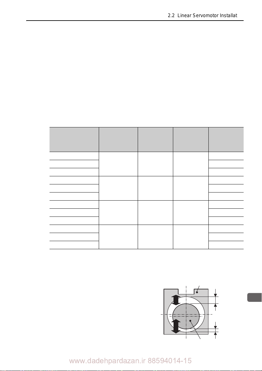
2.2 Linear Servomotor Installation
2
Installation
(4) Others
Magnetic Attraction between Moving Coil and Magnetic Way
Because the steel yoke is embedded in the moving coil to generate force, magn
attraction generates between the moving coil and the magnetic way. When the gap
between the moving coil and the magnetic way is uniform, the magnetic attraction on
the moving coil is offset.
etic
A uniform gap is difficult to obtain, however, because it
depends upon the precision
of the moving coil and the magnetic way products, deflection of the magnetic way,
precision of the equipment of the customer, and assembly error at the time of mounting the motors. In case of non-uniform gap, the attraction shown
in Table 2.3 is gen-
erated. When designing the equipment, take into account the attraction.
Table 2.3 Magnetic Attraction (calculated value)
Moving Coil Model
SGLCW-
D16A085A
D16A115A 30
D16A145A 40
D20A100A
D20A135A 38
D20A170A 50
D25A125A
D25A170A 75
D25A215A 100
D32A165A
D32A225A 120
D32A285A 160
Indicates the gap of the machine when a dislocation of approximately 70% in comparison
to the designed value occurs.
Indicates the magnetic attraction at the time of maximum force.
Note: For the conditions other than those mentioned above, contact Yaskawa representative
separately.
Design Value of
Gap
(mm)
1.0 0.3 1.7
1.25 0.4 2.1
1.5 0.5 2.5
1.75 0.5 3.0
Gap G1
(mm)
*1
Gap G2
(mm)
Moving coil
*1
Difference of
Attraction
*2
F1-F2
(N)
20
25
50
80
The figure shown on the right is an example in which a
non-uniform gap occurs. Actually, magnetic attraction may
be generated and extended in all directions because of an
assembling error or other reasons.
www.dadehpardazan.ir 88594014-15
F2
F1
G2
G1
Magnetic way
2-25
Page 49
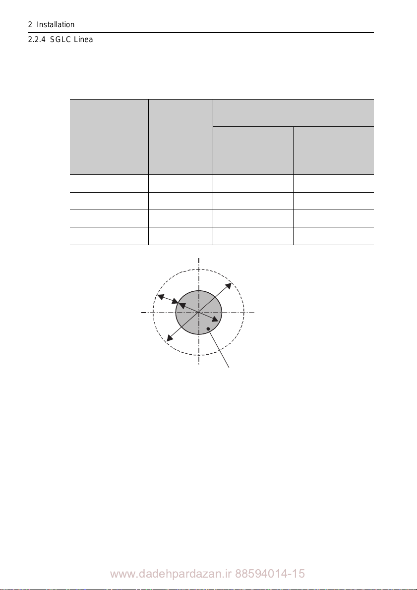
2 Installation
2.2.4 SGLC Linear Servomotors (Cylinder Type)
Leakage Flux of the Magnetic Way
The following table shows the leakage flux of the magnetic way.
Table 2.4 Leakage Flux
Moving Coil Model
SGLCW-
D16
D20
D25
D32
Diameter of
Magnetic Way
D (mm)
16
20 100 220
25 120 265
32 140 312
Places Where the Leakage Flux is 10
Distance from the
Surface of the
Magnetic Way
Gausses or More
Diameter
B (mm)
A (mm)
80 or less 17 6 or less
2-26
D
B
Magnetic way
A
www.dadehpardazan.ir 88594014-15
Page 50

2.3 Linear Scale Installation and Adjustment
2
Installation
2.3 Linear Scale Installation and Adjustment
2.3.1 Installation Conditions
The magnetic flux leaked from a linear servomotor may lead to malfunction of the
linear scale. To avoid such malfunction, determine the linear scale installation location in such environment that the magnetic field strength on the
surface satisfy
the following condition.
linear scale mounted
For the environmental conditions other than magnetic
of the
corresponding linear scale.
Manufacturer Model
SR75/77
Magnescale Co., Ltd.
Mitutoyo Corporation ST78A 3 [mT] max.
SR85/87
SL710/PL101 0.5 [m T] max.
field, refer to the specifications
External Magnetic Field
Strength
5 [mT] max.
The guideline for installation position of each linear servomotor in relation to the
linear scale is
When the linear scale mounting material and/or the
shown in the following pages.
linear servomot
or magnetic way
mounting material are magnetic, installing the linear servomotor on the position
described on the following pages may not satisfy the condition of magnetic field
strength. Use non-magnetic material such as stainless steel and aluminium for the
mounting body, or provide magnetic shielding structure such as magnetic separator
between the linear servomotor magnetic way and the linear scale, and install the
linear scale on the position described in the following pages.
If your machine configuration does not allow the installation of th
e linear servomotor
and the linear scale such way as described on the following pages, measure the
magnetic field strength on the position where the linear scale is actually installed, and
take a counter measure for the magnetic field strength not to exceed the value
specified in the above table.
2-27
www.dadehpardazan.ir 88594014-15
Page 51
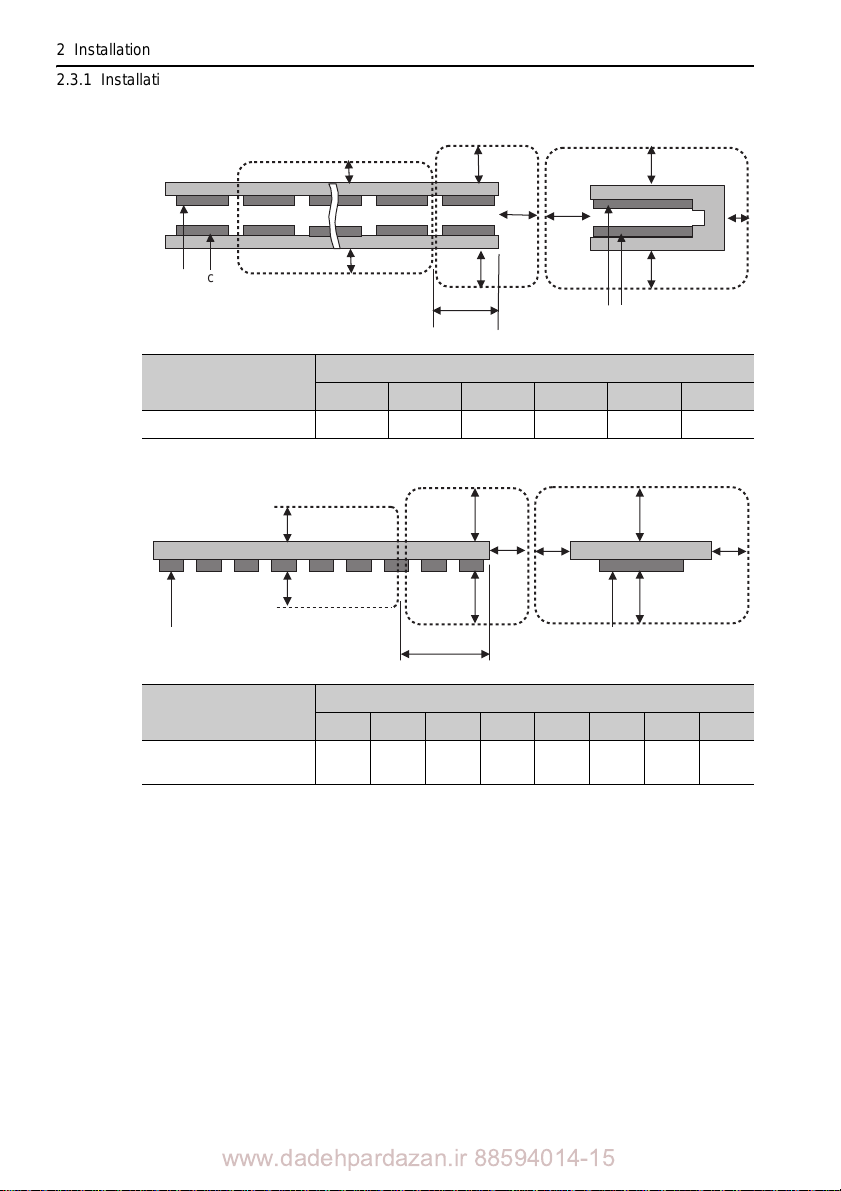
2 Installation
A
EC D
B
A’
B’
A (A’)
B (B’)
X
Magnetic way Magnetic way
2.3.1 Installation Conditions
(1) SGLGM
Magnetic way
Magnetic Way Model
90 10 min. 160 min. 70 min. 70 min. 5 min. 42 min.
(2) SGLFM
Magnetic Way Model
1Z
SGLGM-
SGLFM-
A
A
A’ A (A’)
BC D
A’
X
Magnetic way
A (A’)
Distance from Magnetic Way Surface (mm)
A A' B C D X
Distance from Magnetic Way Surface (mm)
A A' B B' C D D X
120
20
20
10
min.
10
min.
70
min.
min.
min.
min.
30
min.
22.5
min.
2-28
www.dadehpardazan.ir 88594014-15
Page 52
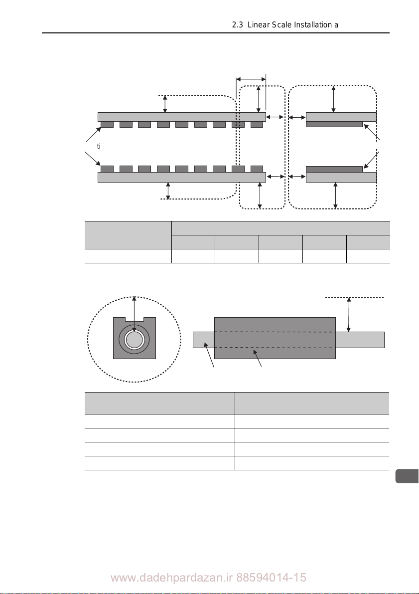
2
Installation
(3) SGLTM
C
X
A’
B
A
A
A’
B
A (A’)
A (A’)
C
Magnetic way
Magnetic way
2.3 Linear Scale Installation and Adjustment
Magnetic Way Model
SGLTM-
Distance from Magnetic Way Surface (mm)
A A' B C X
80 10 min. 10 min. 30 min. 20 min. 22.5 min.
(4) SGLCM
Linear scale mounting position
A
Moving coil
Distance A from Magnetic Way Surface
(mm)
Magnetic Way Model SGLCM-
Magnetic
way
D16A 60 min.
D20A 70 min.
D25A 90 min.
D32A 130 min.
A
www.dadehpardazan.ir 88594014-15
2-29
Page 53
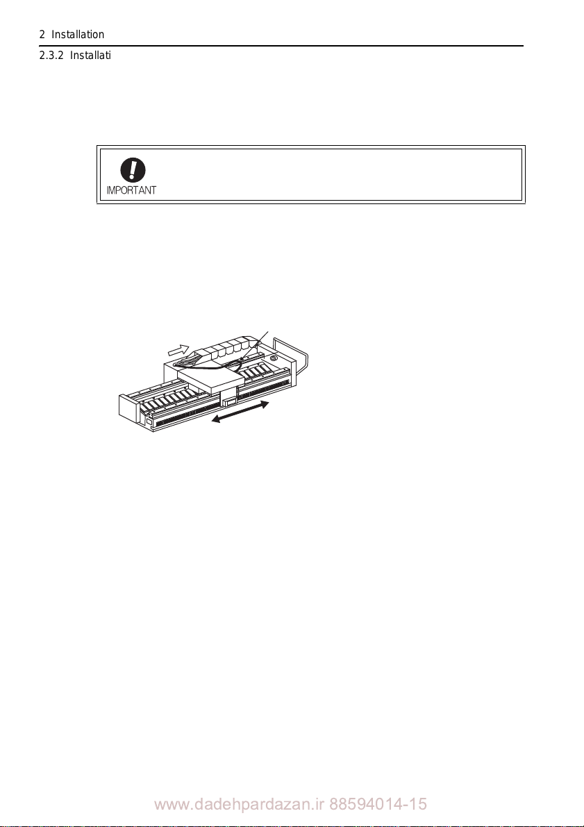
2 Installation
Motor forward direction (U to V to W)
Phase A progression
(pulse increase)
Moving coil cable
Phase B progression
(pulse decrease)
−
+
2.3.2 Installation
2.3.2 Installation
Install the linear scale so that the linear servomotor forward direction and linear scale
count up direction are the same.
When using -V series linear servomotors, the linear servomotor forward direction
(moving coil’s movement direction when current flows through phases U, V, and W,
in that order) is toward the side from which the linear servomotor main circuit cable
is extended. The analog 1-V p-p voltage input from the incremental linear scale to the
serial converter unit is counted during phase A (cos signal) progression.
If the linear servomotor forward direction and linear scale count up
ection do not match and the lin
dir
the linear servomotor may not operate or may overrun.
ear servomotor is run in this state,
Note: When the direction of the linear servomotor and the direction in which the linear scale
counts pulses are reversed because of wiring or other factors, set the parameter
Pn080.1=1 (Sets phase B lead as phase sequence of U, V, W).
2-30
www.dadehpardazan.ir 88594014-15
Page 54
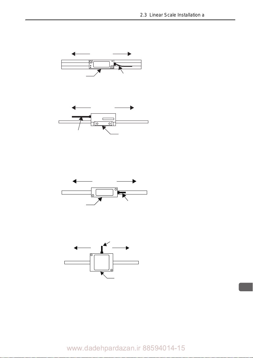
2.3 Linear Scale Installation and Adjustment
2
Installation
Reverse direction
Sensor head Signal cable
Forward direction
LIDA 48
HEIDENHAIN
Reverse direction
Sensor head
Signal cable
Forward direction
Mitsutoyo
(1) Heidenhain Linear Scale
When installed as shown in the diagram
on the left, operation is performed in the
forward direction when the sensor head
is moved to the right.
(2) Renishaw Linear Scale
Forward direction Reverse direction
RENISHAW
RGH22
When installed as shown in the diagram
on the left,
forward direction when the sensor head
is moved to the left.
Signal cable
Sensor head
(3) Mitutoyo Linear Scale
ST781A, ST783A, ST788A, and ST789A
operation is performed
in the
ST782A and ST784A
Reverse direction
www.dadehpardazan.ir 88594014-15
Signal cable
Forward direction
Mitsutoyo
Sensor head
When installed as shown in the diagram
on the left,
forward direction when the sensor head
operation is performed
in the
is moved to the left.
When installed as shown in the diagram
on the left, operation is performed
forward direction when the sensor head
in the
is moved to the right.
2-31
Page 55

2 Installation
Reverse direction Forward direction
Sensor head
Signal cable
Reverese direction Forward direction
Sensor headSignal cable
Reverse directionForward direction
Sensor head
Signal cable
2.3.3 Adjustment
(4) Magnescale Linear Scale
SR75-R, SR85-R, SR77-R, and SR87-R
SR75-L, SR85-L, SR77-L, and SR87-L
SL700, SL710, SL720, and SL730
When installed as shown in the
diagram on the left, operation is
performed in the forward direction when the sensor head is
moved to the ri
When installed as shown in the
diagram on
performed in the forward direction when the sensor head is
moved to the ri
ght.
the left, operation is
ght.
2.3.3 Adjustment
When the linear scale is an open type, adjust the head installation. For details on the
adjustment method, contact the manufacturer of the scales.
When the linear scale is a sealed type, adjustment is not required. However, the
dimensional tolerances for installation must be maintained.
2-32
www.dadehpardazan.ir 88594014-15
When installed as shown in the
diagram on
performed in the forward direction when the sensor head is
moved to the left.
the left, operation is
Page 56
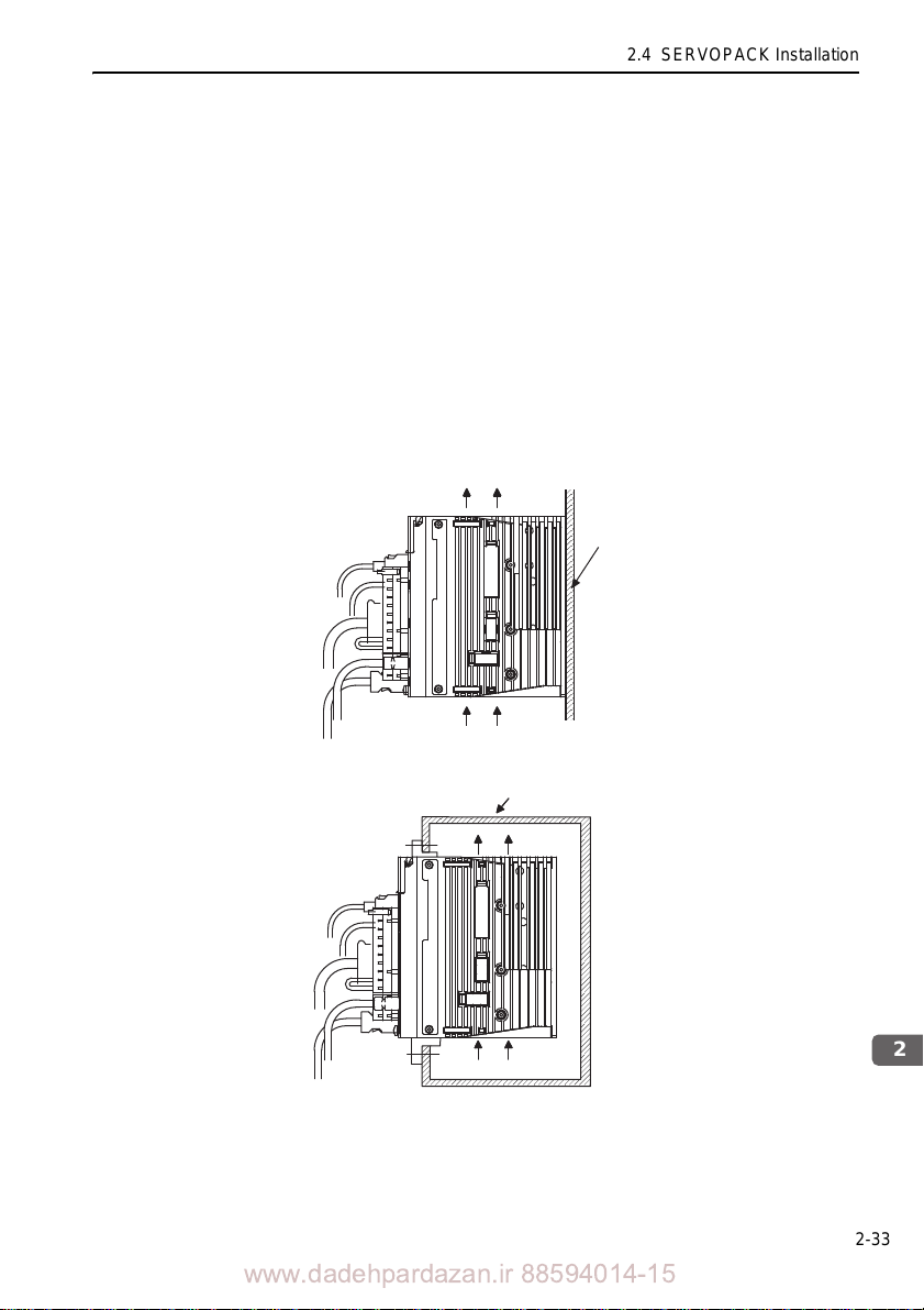
2
Installation
2.4 SERVOPACK Installation
Air Flow
Base
2.4.1 Orientation
The SERVOPACK is available in models that are base-mounted, models that are
rack-mounted, and models that are duct-ventilated. In any case, mount the SERVOPACK with a vertical orientation.
2.4 SERVOPACK Installation
Firmly secure the SERVOPACK to the mounting
surface, using
either two or four
mounting holes depending on the SERVOPACK capacity.
Note: For SERVOPACKs of command option attachable type, installation conditions may dif-
fer depending on the attached option module. For details, refer to the user’s manual for
each option module.
• Base-mounted
• Rack-mounted
Rack
Air Flow
2-33
www.dadehpardazan.ir 88594014-15
Page 57

2 Installation
Air Flow
Duct
2.4.1 Orientation
• Duct-ventilated
2-34
www.dadehpardazan.ir 88594014-15
Page 58
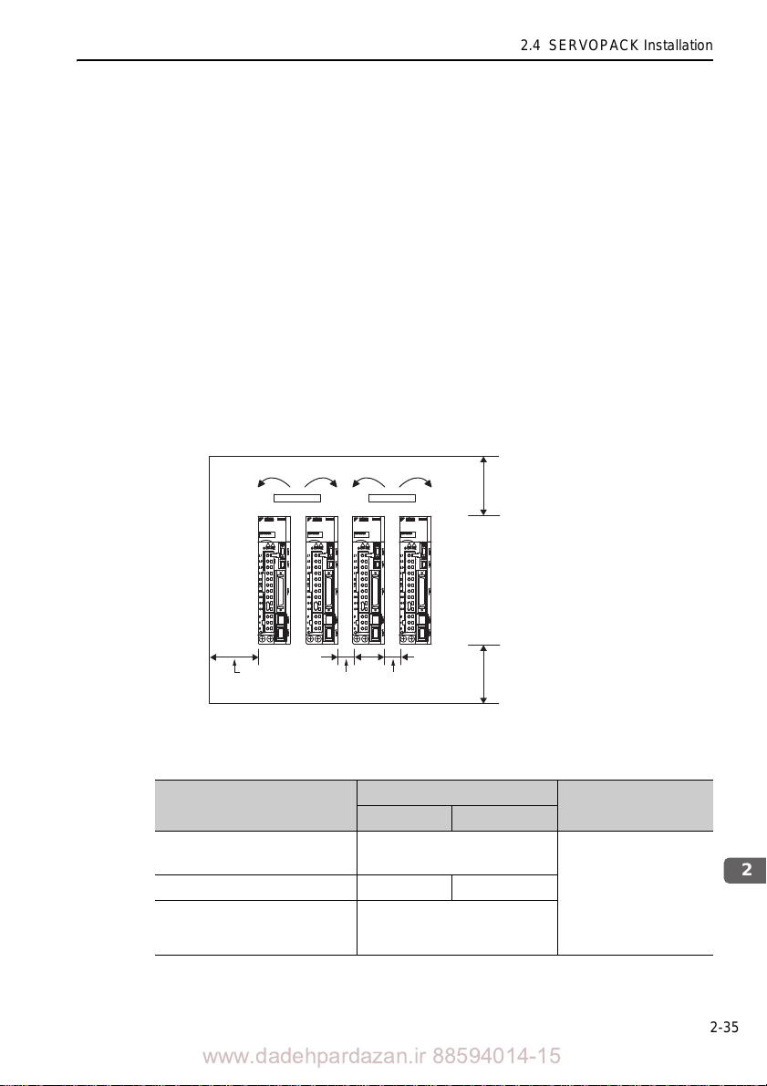
2
Installation
2.4.2 Installation Standards
Fan
30 mm
or more
40 mm or more
40 mm or more
Width varies with
SERVOPACK model
Fan
Observe the standards for mounting SER VOPACKs in control panels, including those
for the mounting SERVOPACKs side by side in one control panel as shown in the
following illustration.
Note: For SERVOPACKs of command option attachable type, installation conditions may dif-
fer depending on the attached option module. For details, refer to the user’s manual for
each option module.
• SERVOPACK Mounting Orientation
Mount the SER VOPACK vertically to the wall, with the front panel (the side with the
panel operator display) facing out.
• Cooling
Refer to the following diagram and leave sufficient space for coolin g by fans an d natural convection.
• Mounting SERVOPACKs Side by Side in a Control Panel
2.4 SERVOPACK Installation
Leave sufficient space on each side and at the top and the bottom of each SERVOPACK. The width on each side varies in accordance with the models of the SERVOPACKS used.
SERVOPACK Model
SGDV-
R70F, R90F, 2R1F,
R70A, R90A, 1R6A, 2R8A
2R8F, 3R8A, 5R5A, 7R6A 1 mm or more 10 mm or more
120A, 180A, 200A, 330A,
550A, 1R9D, 3R5D
8R4D, 120D, 170D, 260D
, 5R4D,
Also install cooling fans above the SER VOP
Side
Left Right
1 mm or more
10 mm or more
ACKs to disperse local pock
Top and bottom
40 mm or more
ets of
warmer air around the SERV OPACKs.
www.dadehpardazan.ir 88594014-15
2-35
Page 59

2 Installation
2.4.2 Installation Standards
• Inside the Control Panel
The conditions inside the control panel should be the same as the environmental conditions of the SERVOPACK. Refer to 2.1.2 SERVOPACK Installation Environment.
The SGDV -B SER VOPACKs have an Installation En
(Un022)
. With this monitor, operation conditions in the installation environment can
vironment monitor
be observed and measured.
The value shown on this monitor should be equal to or less than 100% for optimum
operating conditions.
If this value is over 100%, one of the followin
measures must be taken to ensure
g
safe operation and a long product life.
Improve air circulation around
SERVOPACKs.
Minimum Air Circulation Rate
Top (10 mm): 0.5 m/s
Bottom (10 mm): 0.2 m/s
To improve the air circulation to meet these minimum standards and to lower the per centage shown on the monitor, widen the sp
ace between the SERVOPACKs or lower
the temperature of the surrounding air .
<Note>
For every increase of 10C, the percentage shown on the monitor will also increase
by app
roximately ten.
2-36
www.dadehpardazan.ir 88594014-15
Page 60

2
Installation
2.5 EMC Installation Conditions
Power supply:
Single-phase
100 VAC
U, V, W
L1, L2
L1C, L2C
CN2
CN1
Shield box
SERVOPACK
PE
PE
Linear
scale
Linear
servomotor
Brake
1
3
4
5
Clamp
Noise
filter
Clamp
Clamp
Clamp
CN8
2
Surge
absorber
Two turn
One turn
CoreCore
Core
Core Core
Core
Two turn
Two turn
Clamp
Host
controller
Safety unit
One turn
This section describes the recommended installation conditions that satisfy EMC
guidelines for each model of the SGDV SERVOPACK. The conditions required for
the standard type (base-mounted) of SERVOPACK are described. Refer to this section for other SERVOPACK models such as the rack-mounted types as well.
2.5 EMC Installation Conditions
This section describes the EMC installation conditio
ns satisfied in test conditions
prepared by Yaskawa. The actual EMC level may differ depending on the actual system’s configuration, wiring, and other conditions. However, because this product is
built-in, check that the following conditions are still met after being installed in the
user’s product.
The applicable standards are EN55011/A2 group
1 class
EN61000-6-2.
2.5.1 SGDV-05 (Analog Pulse Model)
Single-phase 100 V, SGDV-F05A ( = R70, R90, 2R1,
2R8)
A, EN61800-3, and
Symbol Cable Name Specification
I/O signal cable Shield cable
Cable for safety unit Shield cable
Linear servomotor main circuit cable Shield cable
Linear scale connection cables Shield cable
Main circuit cable Shield cable
www.dadehpardazan.ir 88594014-15
2-37
Page 61
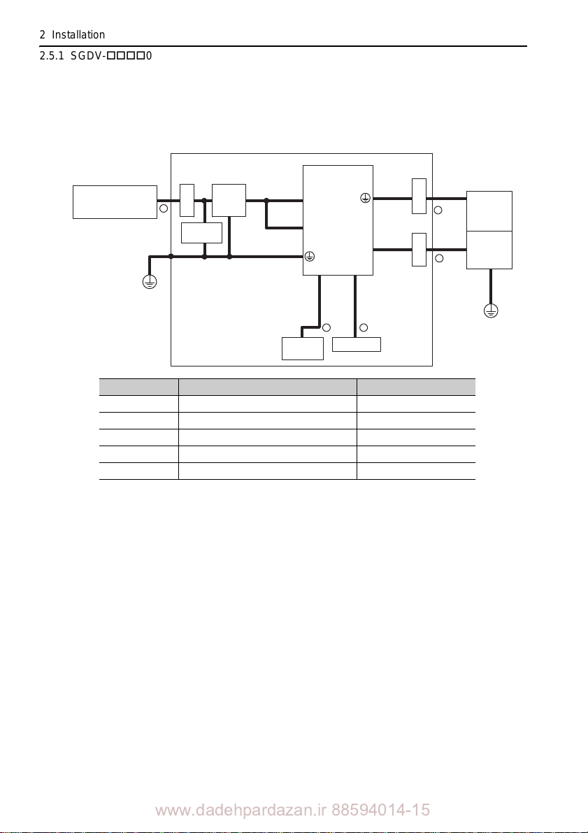
2 Installation
Power supply:
Three-phase
200 VAC
U, V, W
L1, L2, L3
L1C, L2C
CN2
CN1
Shield box
SERVOPACK
PE
PE
1
3
4
5
Clamp
Noise
filter
Clamp
Clamp
CN8
2
Surge
absorber
Linear
scale
Linear
servomotor
Host
controller
Safety unit
2.5.1 SGDV-05 (Analog Pulse Model)
Three-phase 200 V, SGDV-A05B ( = R70, R90, 1R6,
2R8)
Symbol Cable Name Specification
I/O signal cable Shield cable
Cable for safety unit Shield cable
Linear servomotor main circuit cable Shield cable
Linear scale connection cables Shield cable
Main circuit cable Shield cable
2-38
www.dadehpardazan.ir 88594014-15
Page 62
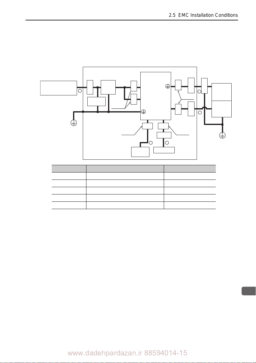
2.5 EMC Installation Conditions
2
Installation
Power supply:
Three-phase
200 VAC
U, V, W
L1, L2, L3
L1C, L2C
CN2
CN1
Shield box
SERVOPACK
PE
PE
1
3
4
5
Clamp
Noise
filter
Clamp
Clamp
Clamp
CN8
2
Surge
absorber
One turn
One turn
CoreCore
Core
Core Core
Core
Two turn
Two turn
Clamp
Linear
scale
Linear
servomotor
Host
controller
Safety unit
Three-phase 200 V, SGDV-A05A ( = R70, R90, 1R6,
2R8, 3R8, 5R5, 7R6)
Symbol Cable Name Specification
I/O signal cable Shield cable
Cable for safety unit Shield cable
Linear servomotor main circuit cable Shield cable
Linear scale connection cables Shield cable
Main circuit cable Shield cable
www.dadehpardazan.ir 88594014-15
2-39
Page 63
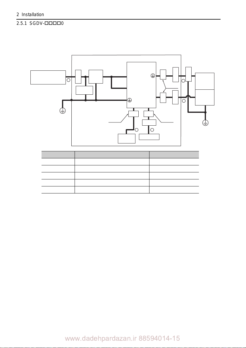
2 Installation
1
3
4
5
2
Power supply:
Three-phase
200 VAC
Shield box
SERVOPACK
Clamp
Noise
filter
Clamp
Clamp
Clamp
Surge
absorber
CoreCore
Core Core
Two turn
Two turn
Clamp
Linear
scale
Linear
servomotor
Host
controller
Safety unit
U, V, W
L1, L2, L3
L1C, L2C
CN2
CN1
PE
PE
CN8
One turn
2.5.1 SGDV-05 (Analog Pulse Model)
Three-phase 200 V, SGDV-120A05A
Symbol Cable Name Specification
I/O signal cable Shield cable
Cable for safety unit Shield cable
Linear servomotor main circuit cable Shield cable
Linear scale connection cables Shield cable
Main circuit cable Shield cable
2-40
www.dadehpardazan.ir 88594014-15
Page 64
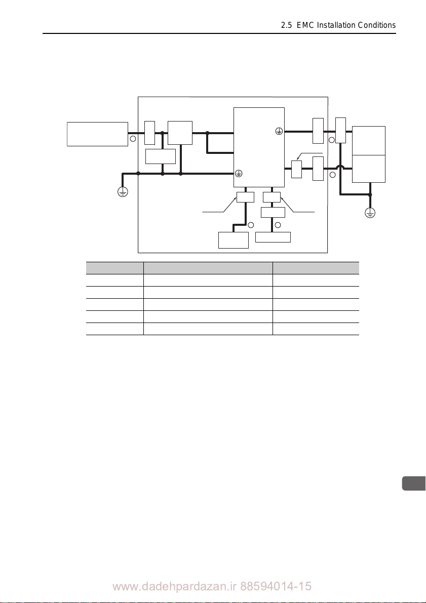
2.5 EMC Installation Conditions
2
Installation
U, V, W
L1, L2, L3
L1C, L2C
CN2
CN1
PE
PE
1
3
4
5
CN8
2
Power supply:
Three-phase
200 VAC
Shield box
SERVOPACK
Clamp
Noise
filter
Clamp
Clamp
Clamp
Surge
absorber
Core
Core Core
Two turn
Two turn
Clamp
Linear
scale
Linear
servomotor
Host
controller
Safety unit
One turn
Three-phase 200 V, SGDV-A05A ( = 180, 200, 330)
Symbol Cable Name Specification
I/O signal cable Shield cable
Cable for safety unit Shield cable
Linear servomotor main circuit cable Shield cable
Linear scale connection cables Shield cable
Main circuit cable Shield cable
www.dadehpardazan.ir 88594014-15
2-41
Page 65
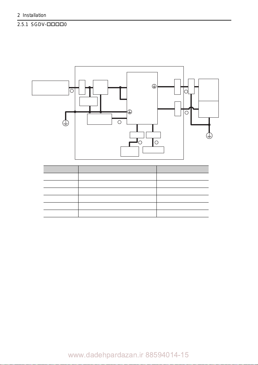
2 Installation
Power supply:
Three-phase
200 VAC
Shield box
SERVOPACK
Noise
filter
Surge
absorber
Host
controller
Safety unit
U, V, W
L1, L2, L3
L1C, L2C
CN2
CN1
B1, B2
PE
PE
Linear
scale
Linear
servomotor
1
3
4
5
Clamp
Clamp
Clamp
Clamp
CN8
2
Clamp Clamp
Regenerative
resistor unit
6
2.5.1 SGDV-05 (Analog Pulse Model)
Three-phase 200 V, SGDV-550A05A
Symbol Cable Name Specification
I/O signal cable Shield cable
Cable for safety unit Shield cable
Linear servomotor main circuit cable Shield cable
Linear scale connection cables Shield cable
Main circuit cable Shield cable
Regenerative resistor unit cable Non-shield cable
2-42
www.dadehpardazan.ir 88594014-15
Page 66
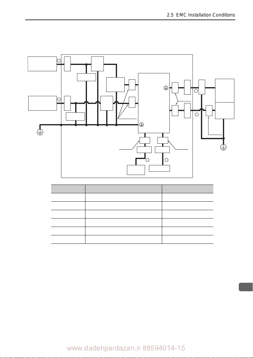
2
Installation
SERVOPACK
Host
controller
Safety unit
Linear
scale
Linear
servomotor
Power supply:
Single-phase
200 VAC
Power supply:
Three-phase
400 VAC
U, V, W
L1, L2, L3
24 V, 0 V
CN2
CN1
Shield box
PE
PE
1
2
3
4
6
5
Clamp
Clamp
Core
Core
Clamp
Core
Core
Clamp
Noise
filter*
3
Core
CN8
Core
Surge
absorber
Surge
absorber
Core
Noise
filter*
2
Control
power
supply
24 VDC*
1
Clamp
Clamp Clamp
One turn
One turn
Two turnTwo turn
One turn
2.5 EMC Installation Conditions
Three-phase 400 V, SGDV-D05A ( = 1R9, 3R5, 5R4,
8R4, 120, 170)
Symbol Cable Name Specification
I/O signal cable Shield cable
Cable for safety unit Shield cable
Linear servomotor main circuit cable Shield cable
Linear scale connection cables Shield cable
Control power cable Shield cable
Main circuit cable Shield cable
Products that have received CE marking are recommended for the 24 VDC power supply.
Install the following noise filter on the power line between th
supply and the 24 VDC power supply.
Model number: FN2070-6/07 (SCHAFFNER)
For more information on this filter, refer to
42)
e single-phase 200 V power
-V Series Product Catalog. (KAEP S80 0000
www.dadehpardazan.ir 88594014-15
2-43
Page 67
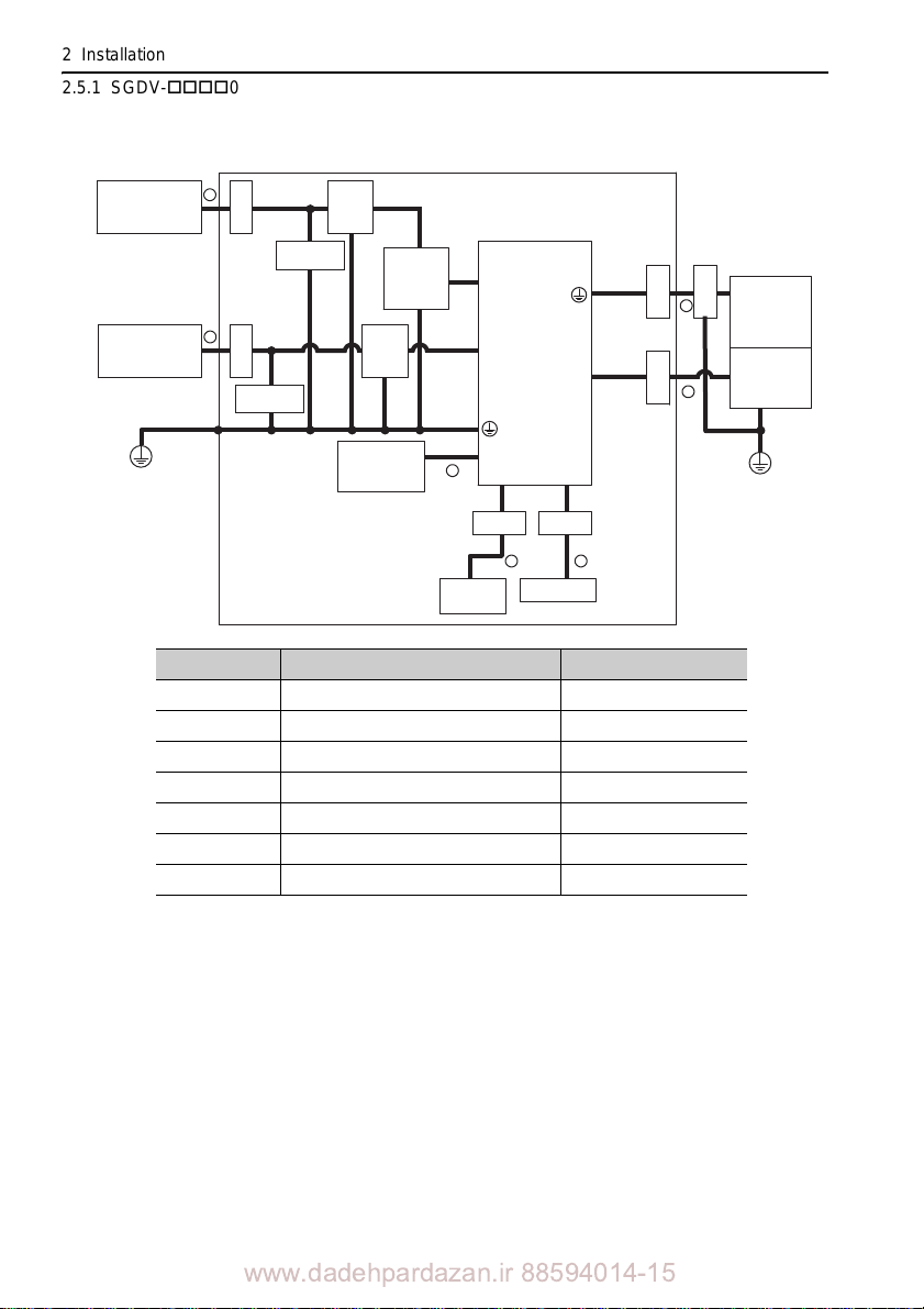
2 Installation
SERVOPACK
Host
controller
Safety unit
Linear
scale
Linear
servomotor
Power supply:
Single-phase
200 VAC
Power supply:
Three-phase
400 VAC
U, V, W
L1, L2, L3
24 V, 0 V
CN2
CN1
Shield box
PE
PE
1
2
3
4
6
5
Clamp
Clamp
Clamp
Clamp
Noise
filter*
3
CN8
Surge
absorber
Surge
absorber
Noise
filter*
2
Control
power
supply
24 VDC*
1
Clamp
Clamp Clamp
B1, B2
Regenerative
resistor unit
cable
7
2.5.1 SGDV-05 (Analog Pulse Model)
Three-phase 400 V, SGDV-260D05A
Symbol Cable Name Specification
I/O signal cable Shield cable
Cable for safety unit Shield cable
Linear servomotor main circuit cable Shield cable
Linear scale connection cables Shield cable
Control power cable Shield cable
Main circuit cable Shield cable
Regenerative resistor unit cable Non-shield cable
Products that have received CE marking are recommended for the 24 VDC power supply.
Install the following noise filter on the power
supply and the 24 VDC power supply.
Model number: FN2070-6/07 (SCHAFFNER)
For more information on this filter, refer to
42)
line between the single-phase 200 V power
-V Series Product Catalog. (KAEP S8 00000
2-44
www.dadehpardazan.ir 88594014-15
Page 68

2
Installation
2.5.2 SGDV-15 (M-II Model)
U, V, W
L1, L2
L1C, L2C
CN2
CN1
Shield box
PE
PE
1
3
4
5
Clamp
Clamp
Clamp
CN8
2
One turn
CoreCore
Two turn
Two turn
Clamp
MECHATROLINK-II
controller
CN6A,CN6B
6
Clamp
Power supply:
Single-phase
100 VAC
SERVOPACK
Linear
scale
Linear
servomotor
Clamp
Noise
filter
Surge
absorber
Two turn
Core
Core Core
Core
Safety unit
One turn
Host
controller
Single-phase 100 V, SGDV-F15A ( = R70, R90, 2R1,
2R8)
2.5 EMC Installation Conditions
Symbol Cable Name Specification
I/O signal cable Shield cable
Cable for safety unit Shield cable
Linear servomotor main circuit cable Shield cable
Linear scale connection cables Shield cable
2-45
Main circuit cable Shield cable
MECHATROLINK-II communication cable Shield cable
www.dadehpardazan.ir 88594014-15
Page 69
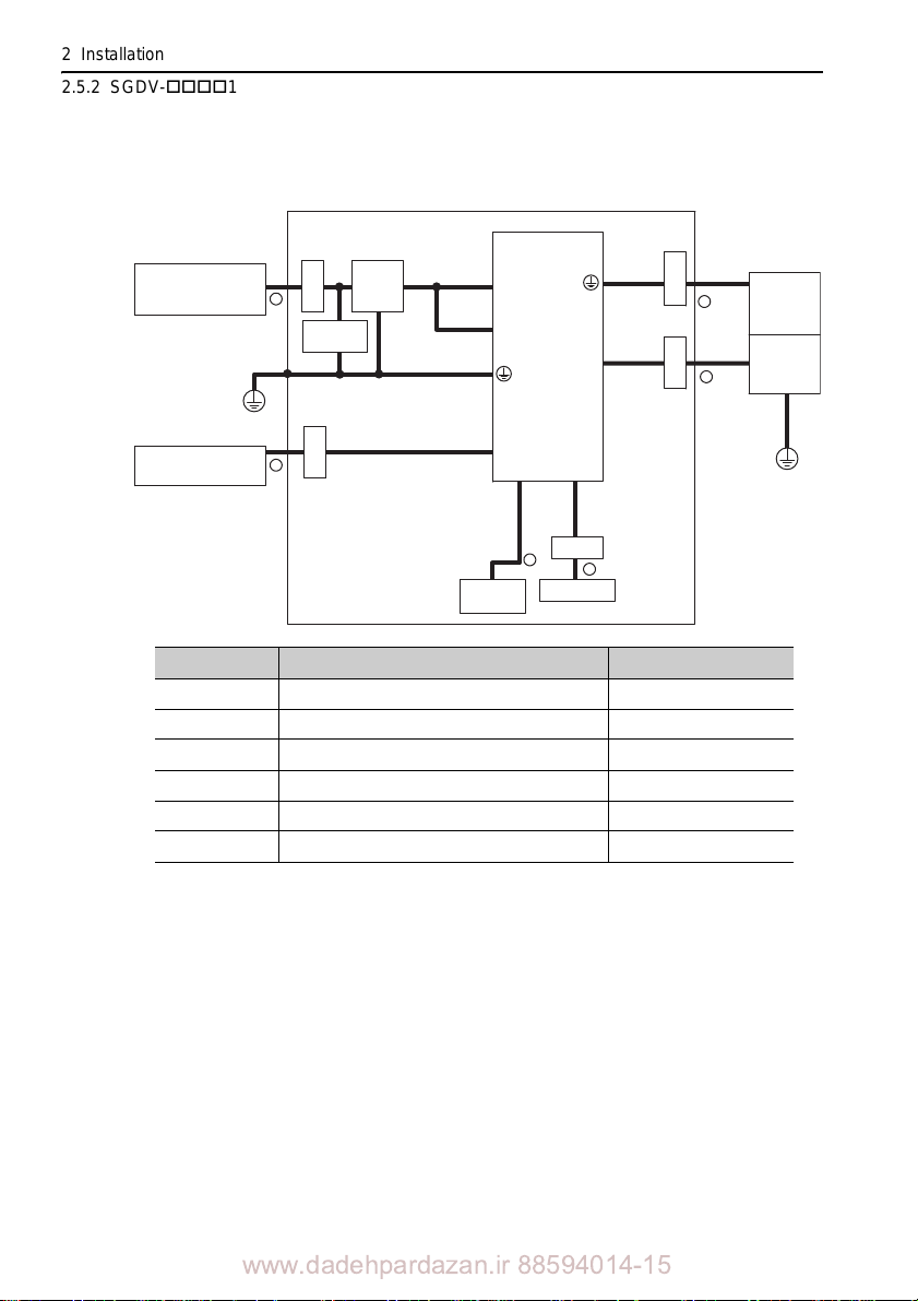
2 Installation
Shield box
Clamp
Clamp
Clamp
MECHATROLINK-II
controller
Clamp
Power supply:
Three-phase
200 VAC
SERVOPACK
Linear
scale
Linear
servomotor
Clamp
Noise
filter
Surge
absorber
Safety unit
U, V, W
L1, L2, L3
L1C, L2C
CN2
CN1
CN6A, CN6B
PE
PE
2
1
3
4
5
6
CN8
Host
controller
2.5.2 SGDV-15 (M-II Model)
Three-phase 200 V, SGDV-A15B ( = R70, R90, 1R6,
2R8)
Symbol Cable Name Specification
I/O signal cable Shi eld cable
Cable for safety unit Shield cable
Linear servomotor main circuit cable Shield cable
Linear scale connection cables Shield cable
Main circuit cable Shield cable
MECHATROLINK-II communication cable Shield cable
2-46
www.dadehpardazan.ir 88594014-15
Page 70
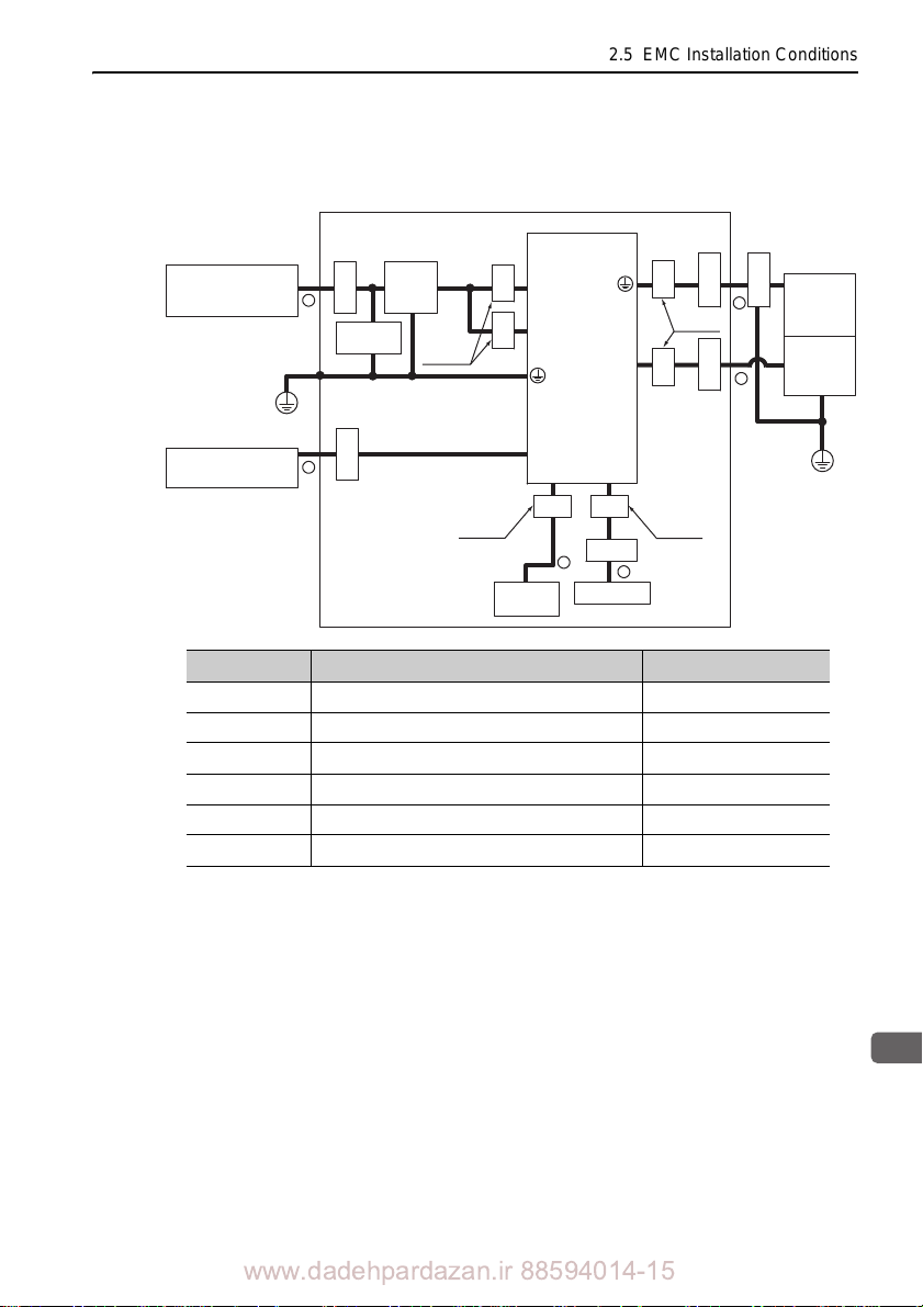
2.5 EMC Installation Conditions
2
Installation
Shield box
Clamp
Clamp
Clamp
One turn
CoreCore
Two turn
Two turn
Clamp
MECHATROLINK-II
controller
Clamp
Power supply:
Three-phase
200 VAC
SERVOPACK
Linear
scale
Linear
servomotor
Clamp
Noise
filter
Surge
absorber
Core
Core Core
Core
Safety unit
U, V, W
L1, L2, L3
L1C, L2C
CN2
CN1
CN6A, CN6B
PE
PE
2
1
3
4
5
6
CN8
One turn
Host
controller
Three-phase 200 V, SGDV-A15A ( = R70, R90, 1R6,
2R8, 3R8, 5R5, 7R6)
Symbol Cable Name Specification
I/O signal cable Shield cable
Cable for safety unit Shield cable
Linear servomotor main circuit cable Shield cable
Linear scale connection cables Shield cable
Main circuit cable Shield cable
MECHATROLINK-II communication cable Shield cable
www.dadehpardazan.ir 88594014-15
2-47
Page 71
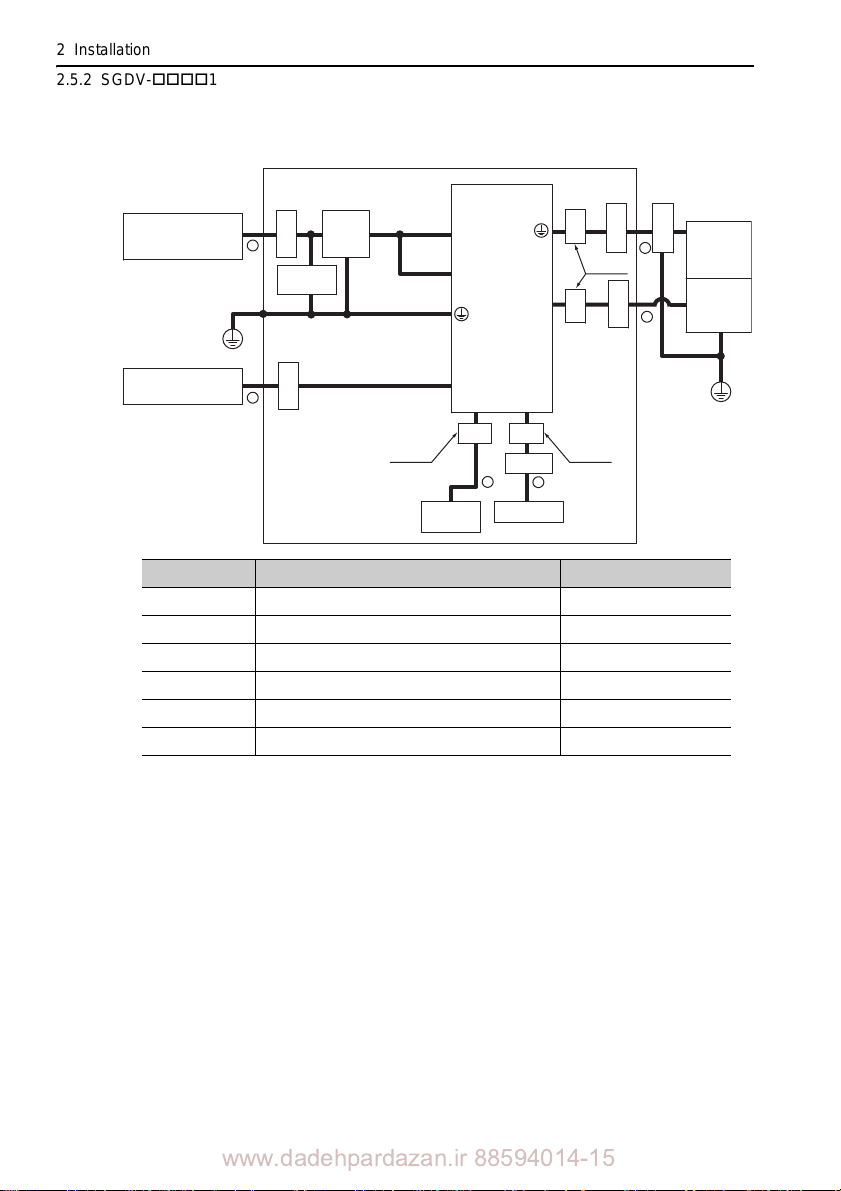
2 Installation
U, V, W
L1, L2, L3
L1C, L2C
CN2
CN1
CN6A, CN6B
PE
PE
2
1
3
4
5
6
CN8
Shield box
Clamp
Clamp
Clamp
One turn
CoreCore
Two turn
Two turn
Clamp
MECHATROLINK-II
controller
Clamp
Power supply:
Three-phase
200 VAC
SERVOPACK
Linear
scale
Linear
servomotor
Clamp
Noise
filter
Surge
absorber
Core Core
Safety unit
Host
controller
2.5.2 SGDV-15 (M-II Model)
Three-phase 200 V, SGDV-120A15A
Symbol Cable Name Specification
I/O signal cable Shield cable
Cable for safety unit Shield cable
Linear servomotor main circuit cable Shield cable
Linear scale connection cables Shield cable
Main circuit cable Shield cable
MECHATROLINK-II communication cable Shield cable
2-48
www.dadehpardazan.ir 88594014-15
Page 72
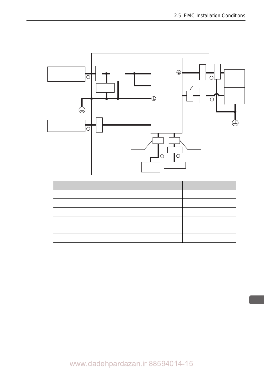
2.5 EMC Installation Conditions
2
Installation
U, V, W
L1, L2, L3
L1C, L2C
CN2
CN1
PE
PE
1
3
4
5
CN8
2
CN6A, CN6B
6
Shield box
Clamp
Clamp
Clamp
One turn
Core
Two turn
Two turn
Clamp
MECHATROLINK-II
controller
Clamp
Power supply:
Three-phase
200 VAC
SERVOPACK
Linear
scale
Linear
servomotor
Clamp
Noise
filter
Surge
absorber
Core Core
Safety unit
Host
controller
Three-phase 200 V, SGDV-A15A ( = 180, 200, 330)
Symbol Cable Name Specification
I/O signal cable Shield cable
Cable for safety unit Shield cable
Linear servomotor main circuit cable Shield cable
Linear scale connection cables Shield cable
Main circuit cable Shield cable
MECHATROLINK-II communication cable Shield cable
www.dadehpardazan.ir 88594014-15
2-49
Page 73
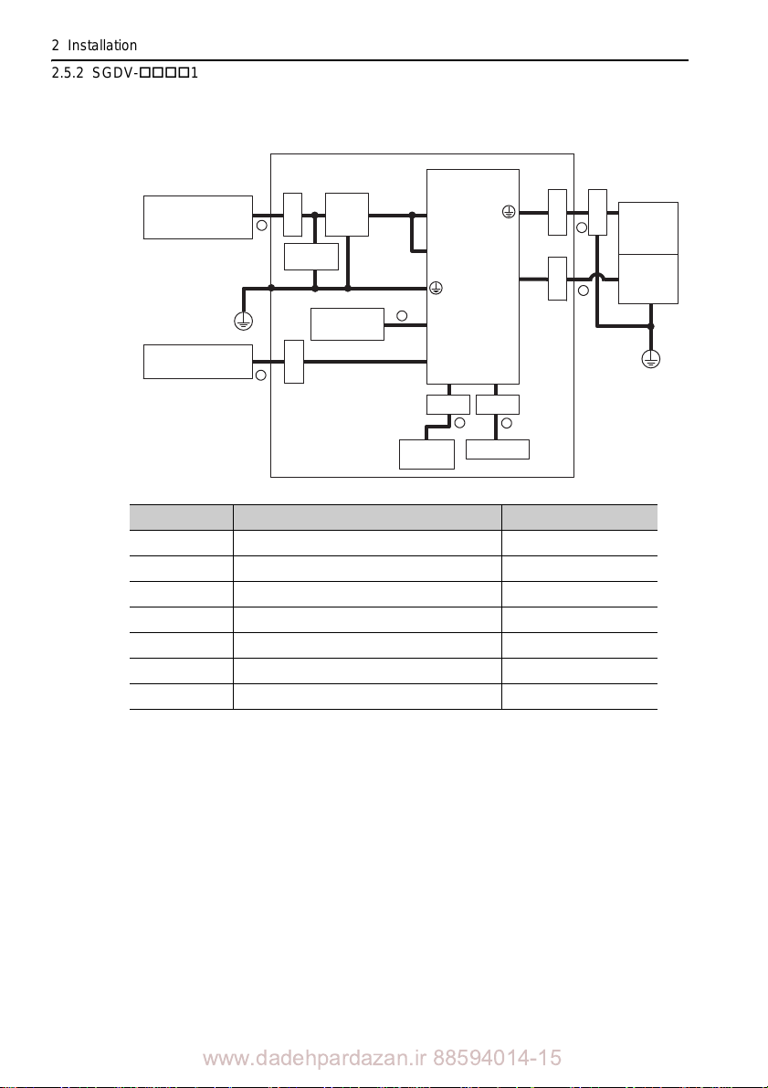
2 Installation
U, V, W
L1, L2, L3
L1C, L2C
B1, B2
CN2
CN1
PE
PE
1
3
4
5
CN8
2
MECHATROLINK-II
controller
CN6A, CN6B
Clamp
6
7
Power supply:
Three-phase
200 VAC
Shield box
SERVOPACK
Noise
filter
Surge
absorber
Safety unit
Linear
scale
Linear
servomotor
Clamp
Clamp
Clamp
Clamp
Clamp Clamp
Regenerative
resistor unit
Host
controller
2.5.2 SGDV-15 (M-II Model)
Three-phase 200 V, SGDV-550A15A
Symbol Cable Name Specification
I/O signal cable Shield cable
Cable for safety unit Shield cable
Linear servomotor main circuit cable Shield cable
Linear scale connection cables Shield cable
Main circuit cable Shield cable
Regenerative resistor unit cable Non-shield cable
MECHA TROLINK-II communication cable Shield cable
2-50
www.dadehpardazan.ir 88594014-15
Page 74
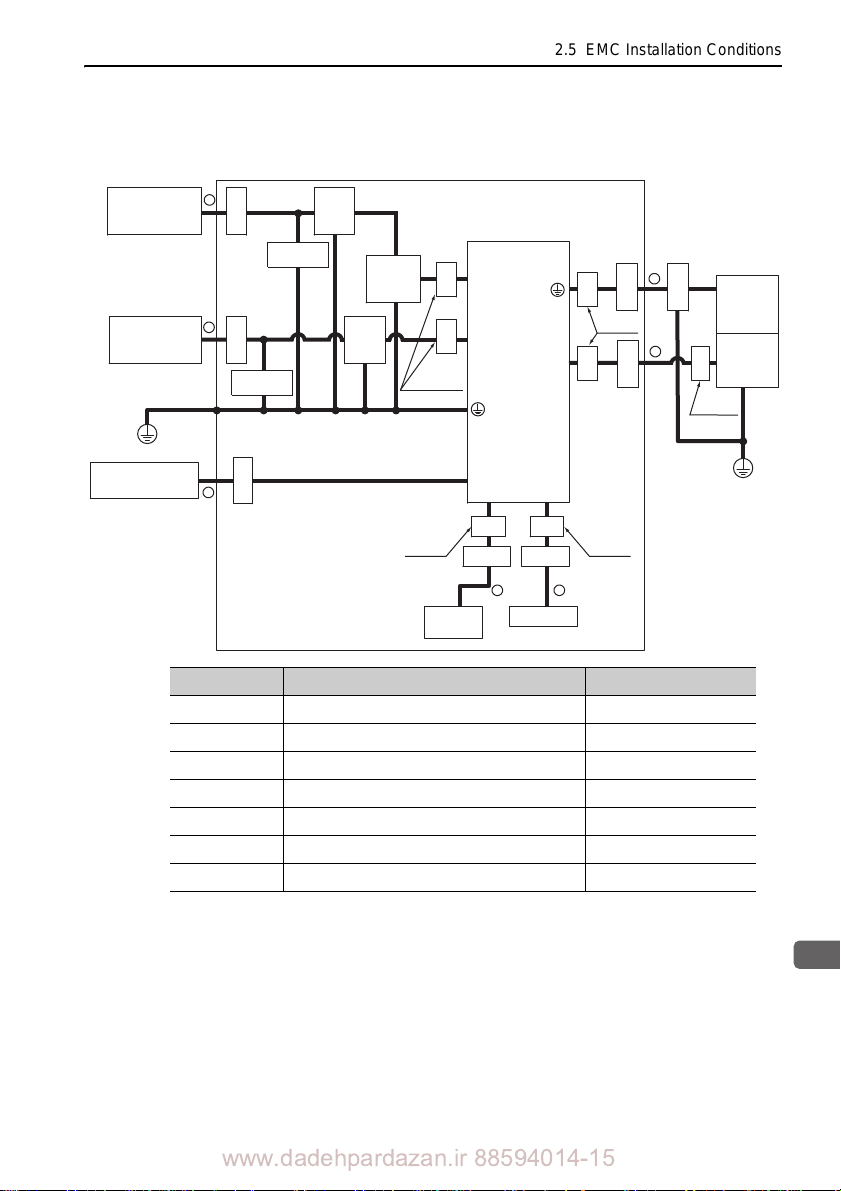
2.5 EMC Installation Conditions
2
Installation
U, V, W
L1, L2, L3
24 V, 0 V
CN2
CN1
PE
PE
1
2
3
6
5
CN8
4
CN6A, CN6B
7
Clamp
MECHATROLINK-II
controller
SERVOPACK
Safety unit
Linear
scale
Linear
servomotor
Power supply:
Single-phase
200 VAC
Power supply:
Three-phase
400 VAC
Shield box
Clamp
Clamp
Core
Core
Clamp
Core
Core
Clamp
Noise
filter*
3
Core Core
Surge
absorber
Surge
absorber
Core
Noise
filter*
2
Control
power
supply
24 VDC*
1
Clamp
Clamp Clamp
One turn
One turn
Two turnTwo turn
One turn
Host
controller
Three-phase 400 V, SGDV-D15A ( = 1R9, 3R5, 5R4,
8R4, 120, 170)
Symbol Cable Name Specification
I/O signal cable Shield cable
Cable for safety unit Shield cable
Linear servomotor main circuit cable Shield cable
Linear scale connection cables Shield cable
Control power cable Shield cable
Main circuit cable Shield cable
MECHATROLINK-II communication cable Shield cable
Products that have received CE marking are recommended for the 24 VDC power supply.
Install the following noise filter on the power line between th
supply and the 24 VDC power supply.
e single-phase 200 V power
Model number: FN2070-6/07 (SCHAFFNER)
For more information on this filter, refer to
42)
www.dadehpardazan.ir 88594014-15
-V Series Product Catalog. (KAEP S80 0000
2-51
Page 75
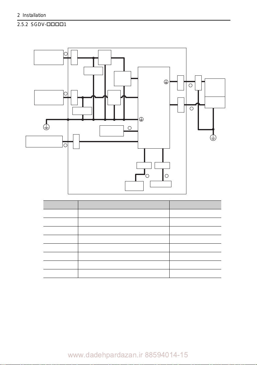
2 Installation
2.5.2 SGDV-15 (M-II Model)
Three-phase 400 V, SGDV-260D15A
Power supply:
Single-phase
200 VAC
Power supply:
Three-phase
400 VAC
5
Clamp
Surge
absorber
6
Clamp
Surge
absorber
Noise
filter*
2
Noise
filter*
Control
power
supply
24 VDC*
3
1
SERVOPACK
24 V, 0 V
L1, L2, L3
U, V, W
CN2
Shield box
Clamp
Clamp
3
4
Clamp
servomotor
Linear
Linear
scale
PE
MECHATROLINK-II
controller
Regenerative
resistor cable
8
Clamp
7
B1, B2
CN6A, CN6B
Clamp Clamp
Host
controller
CN1
1
Safety unit
CN8
2
Symbol Cable Name Specification
I/O signal cable Shield cable
Cable for safety unit Shield cable
Linear servomotor main circuit cable Shield cable
Linear scale connection cables Shield cable
Control power cable Shield cable
Main circuit cable Shield cable
Regenerative resistor unit cable Non-shield cable
MECHATROLINK-II communication cable Shield cable
Products that have received CE marking are recommended for the 24 VDC power supply.
Install the following noise filter on the power
line between the single-phase 200 V power
supply and the 24 VDC power supply.
Model number: FN2070-6/07 (SCHAFFNER)
For more information on this filter, refer to
-V Series Product Catalog. (KAEP S8 00000
42)
PE
2-52
www.dadehpardazan.ir 88594014-15
Page 76
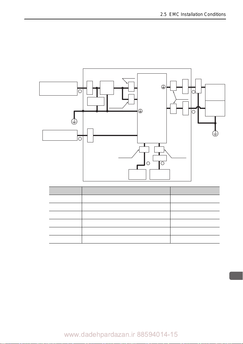
2
Installation
2.5.3 SGDV-25 (M-III Model)
Single-phase 100 V, SGDV-F25A ( = R70, R90, 2R1,
2R8)
2.5 EMC Installation Conditions
Shield box
Power supply:
Single-phase 100 VAC
MECHATROLINK-III
controller
PE
One turn
Noise
Clamp
Surge
absorber
Clamp
filter
Two turn
5
6
L1, L2
Core
L1C, L2C
Core
CN6A, CN6B
Host
controller
SERVOPACK
U, V, W
CN1
CN8
Core Core
Clamp
1
Safety unit
CN2
2
Symbol Cable Name Specification
I/O signal cable Shield cable
Cable for safety unit Shield cable
Linear servomotor main circuit cable Shield cable
Linear scale connection cables Shield cable
Main circuit cable Shield cable
MECHATROLINK-III communication cable Shield cable
CoreCore
One turn
Two turnTwo turn
Clamp
Clamp
Clamp
Linear
3
servomotor
Linear
4
scale
PE
2-53
www.dadehpardazan.ir 88594014-15
Page 77
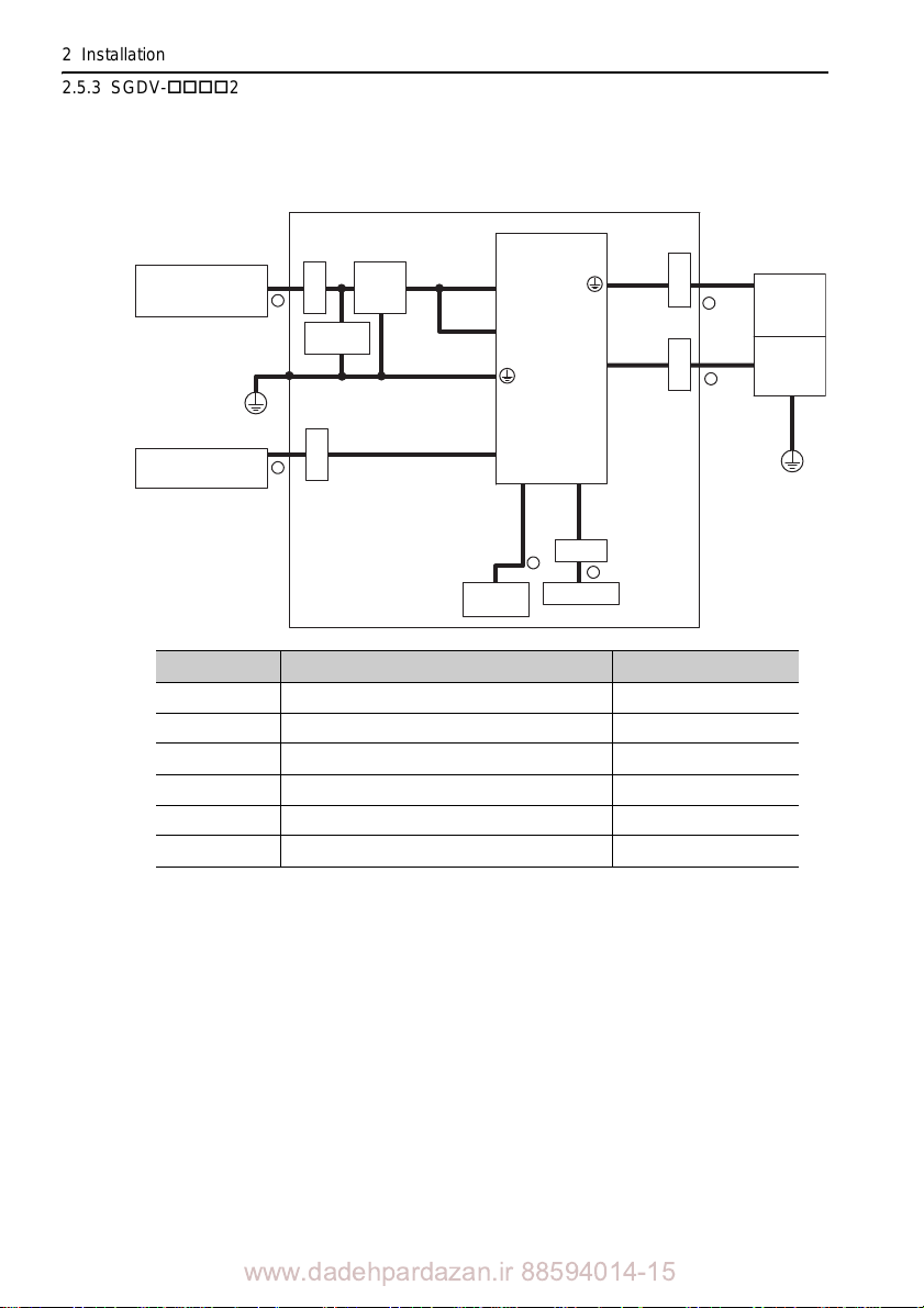
2 Installation
Shield box
Clamp
Clamp
Clamp
MECHATROLINK-III
controller
Clamp
Power supply:
Three-phase
200 VAC
SERVOPACK
Linear
scale
Linear
servomotor
Clamp
Noise
filter
Surge
absorber
Safety unit
U, V, W
L1, L2, L3
L1C, L2C
CN2
CN1
CN6A, CN6B
PE
PE
2
1
3
4
5
6
CN8
Host
controller
2.5.3 SGDV-25 (M-III Model)
Three-phase 200 V, SGDV-A25B ( = R70, R90, 1R6,
2R8)
Symbol Cable Name Specification
I/O signal cable Shi eld cable
Cable for safety unit Shield cable
Linear servomotor main circuit cable Shield cable
Linear scale connection cables Shield cable
Main circuit cable Shield cable
MECHATROLINK-III communication cable Shi
eld cable
2-54
www.dadehpardazan.ir 88594014-15
Page 78
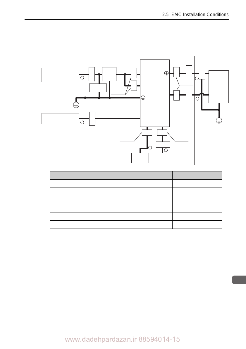
2.5 EMC Installation Conditions
2
Installation
MECHATROLINK-III
controller
U, V, W
L1, L2, L3
L1C, L2C
CN2
CN1
CN6A, CN6B
Shield box
SERVOPACK
PE
PE
Linear
scale
Linear
servomotor
Clamp
Noise
filter
Clamp
Clamp
Clamp
CN8
Surge
absorber
CoreCore
Core
Core Core
Core
Clamp
Host
controller
Safety unit
Clamp
Power supply:
Three-phase 200 VAC
5
6
One turn
One turn
Two turn Two turn
1
2
3
4
Three-phase 200 V, SGDV -A25A ( =R70, R90, 1R6, 2R8,
3R8, 5R5, 7R6)
Symbol Cable Name Specification
I/O signal cable Shield cable
Cable for safety unit Shield cable
Linear servomotor main circuit cable Shield cable
Linear scale connection cables Shield cable
Main circuit cable Shield cable
MECHATROLINK-III communication cable Shield cable
www.dadehpardazan.ir 88594014-15
2-55
Page 79
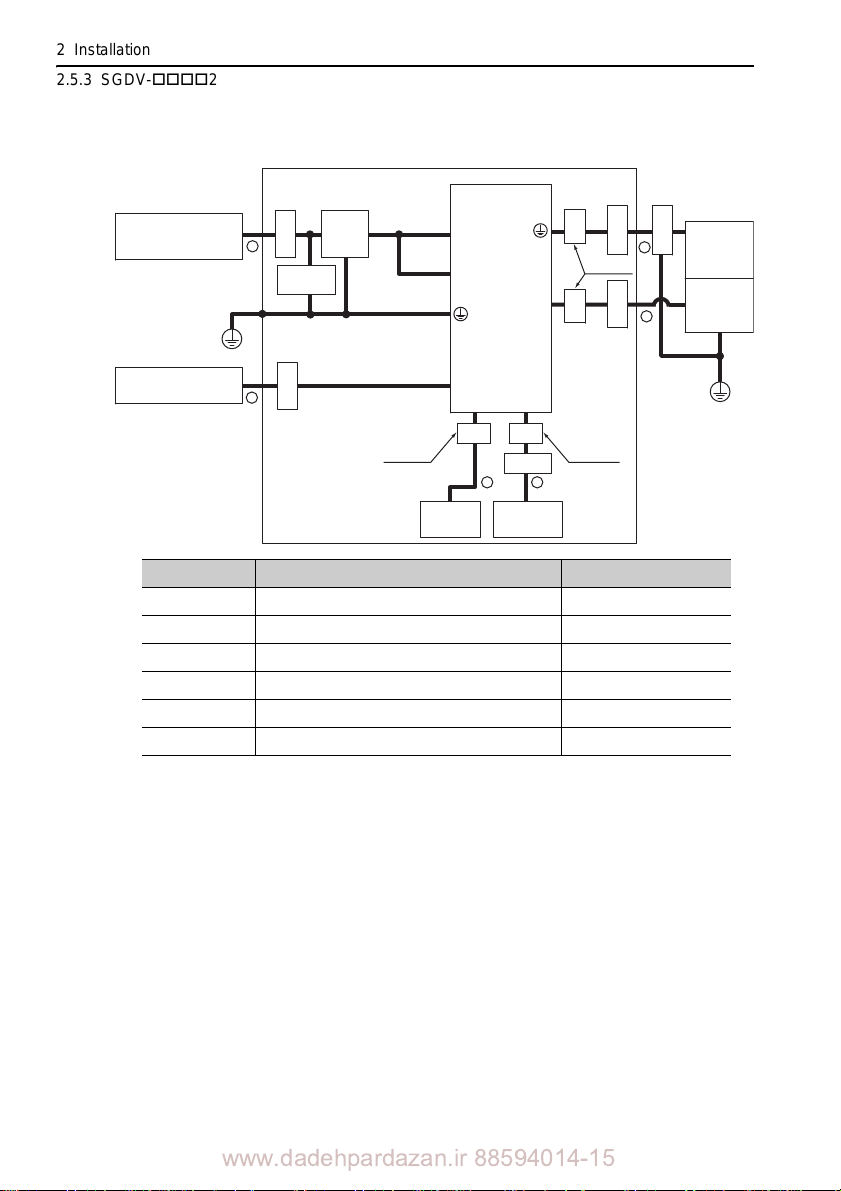
2 Installation
MECHATROLINK-III
controller
U, V, W
L1, L2, L3
L1C, L2C
CN2
CN1
CN6A, CN6B
SERVOPACK
PE
PE
Linear
scale
Linear
servomotor
Clamp
Noise
filter
Clamp
Clamp
Clamp
CN8
Surge
absorber
CoreCore
Core Core
Clamp
Host
controller
Safety unit
Clamp
Power supply:
Three-phase 200 VAC
One turn
Shield box
Two turn Two turn
5
6
12
3
4
2.5.3 SGDV-25 (M-III Model)
Three-phase 200 V, SGDV-120A25A
Symbol Cable Name Specification
I/O signal cable Shield cable
Cable for safety unit Shield cable
Linear servomotor main circuit cable Shield cable
Linear scale connection cables Shield cable
Main circuit cable Shield cable
MECHATROLINK-III communication cable Shield ca
ble
2-56
www.dadehpardazan.ir 88594014-15
Page 80
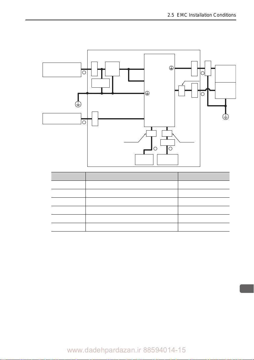
2.5 EMC Installation Conditions
2
Installation
Power supply:
Three-phase 200 VAC
U, V, W
L1, L2, L3
L1C, L2C
CN2
CN1
SERVOPACK
PE
PE
Linear
scale
Linear
servomotor
Clamp
Noise
filter
Clamp
Clamp
Clamp
CN8
Surge
absorber
Core
Core Core
Clamp
Host
controller
Safety unit
MECHATROLINK-III
controller
CN6A, CN6B
Clamp
Shield box
One turn
Two turn Two turn
5
6
12
3
4
Three-phase 200 V, SGDV-A25A ( = 180, 200, 330)
Symbol Cable Name Specification
I/O signal cable Shield cable
Cable for safety unit Shield cable
Linear servomotor main circuit cable Shield cable
Linear scale connection cables Shield cable
Main circuit cable Shield cable
MECHATROLINK-III communication cable Shield cable
www.dadehpardazan.ir 88594014-15
2-57
Page 81
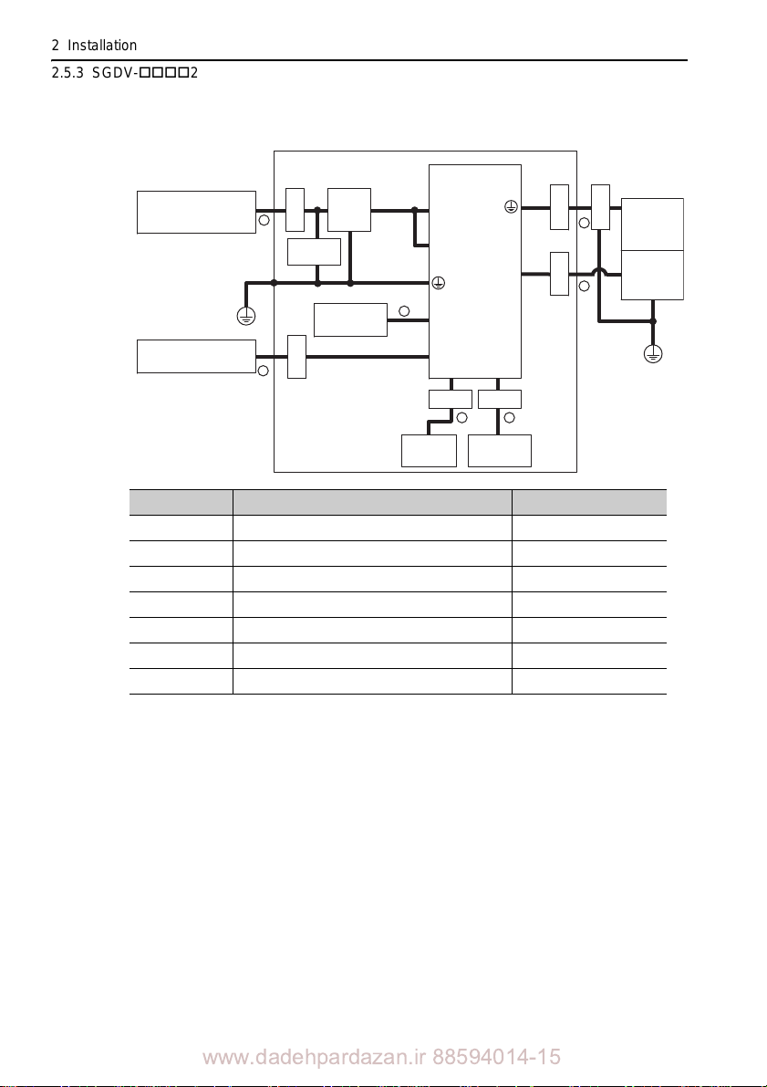
2 Installation
2.5.3 SGDV-25 (M-III Model)
Three-phase 200 V, SGDV-550A25A
Power supply:
Three-phase 200 VAC
MECHATROLINK-III
controller
Symbol Cable Name Specification
I/O signal cable Shield cable
Cable for safety unit Shield cable
Linear servomotor main circuit cable Shield cable
Linear scale connection cables Shield cable
Main circuit cable Shield cable
Regenerative resistor unit cable Non-shield cable
MECHATROLINK-III communication cable Shield ca
5
absorber
PE
7
Clamp
Surge
Regenerative
resistor unit
Clamp
Noise
filter
6
Host
controller
SERVOPACK
U, V, W
L1, L2, L3
L1C, L2C
B1, B2
CN6A, CN6B
CN1
CN8
ClampClamp
12
Safety unit
CN2
Shield box
Clamp
Clamp
ble
Linear
Clamp
3
servomotor
Linear
4
scale
PE
2-58
www.dadehpardazan.ir 88594014-15
Page 82
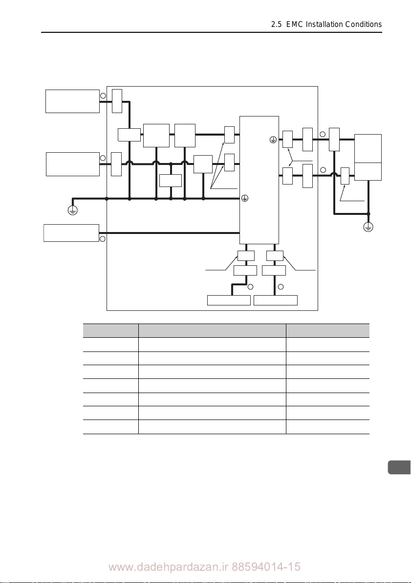
2.5 EMC Installation Conditions
2
Installation
1
2
3
6
5
4
7
U, V, W
L1, L2, L3
24 V,
0 V
CN2
CN1
PE
PE
CN8
CN6A, CN6B
MECHATROLINK-III
controller
SERVOPACK
Safety unit
Linear
scale
Linear
servomotor
Power supply:
Single-phase
200 VAC
Power supply:
Three-phase
400 VAC
Shield box
Clamp
Clamp
Core
Core
Clamp
Core
Core
Clamp
Noise
filter*
3
Core Core
Surge
absorber
Surge
absorber
Core
Noise
filter*
2
Control
power
supply
24 VDC*
1
Clamp
Clamp Clamp
One turn
One turn
Two turnTwo turn
One turn
Host controller
Three-phase 400 V, SGDV-D25A ( = 1R9, 3R5, 5R4,
8R4, 120, 170)
Symbol Cable Name Specification
I/O signal cable Shield cable
Linear servomotor main circuit cable Shield cable
Linear scale connection cables Shield cable
Control power cable Shield cable
Main circuit cable Shield cable
MECHATROLINK-III communication cable Shield cable
Products that have received CE marking are recommended for the 24 VDC power supply.
Install the following noise filter on the power line between th
supply and the 24 VDC power supply.
Model number: FN2070-6/07 (SCHAFFNER)
For more information on this filter, refer to
Cable for safety unit Shield cable
e single-phase 200 V power
-V Series Product Catalog. (KAEP S80 0000
42)
www.dadehpardazan.ir 88594014-15
2-59
Page 83
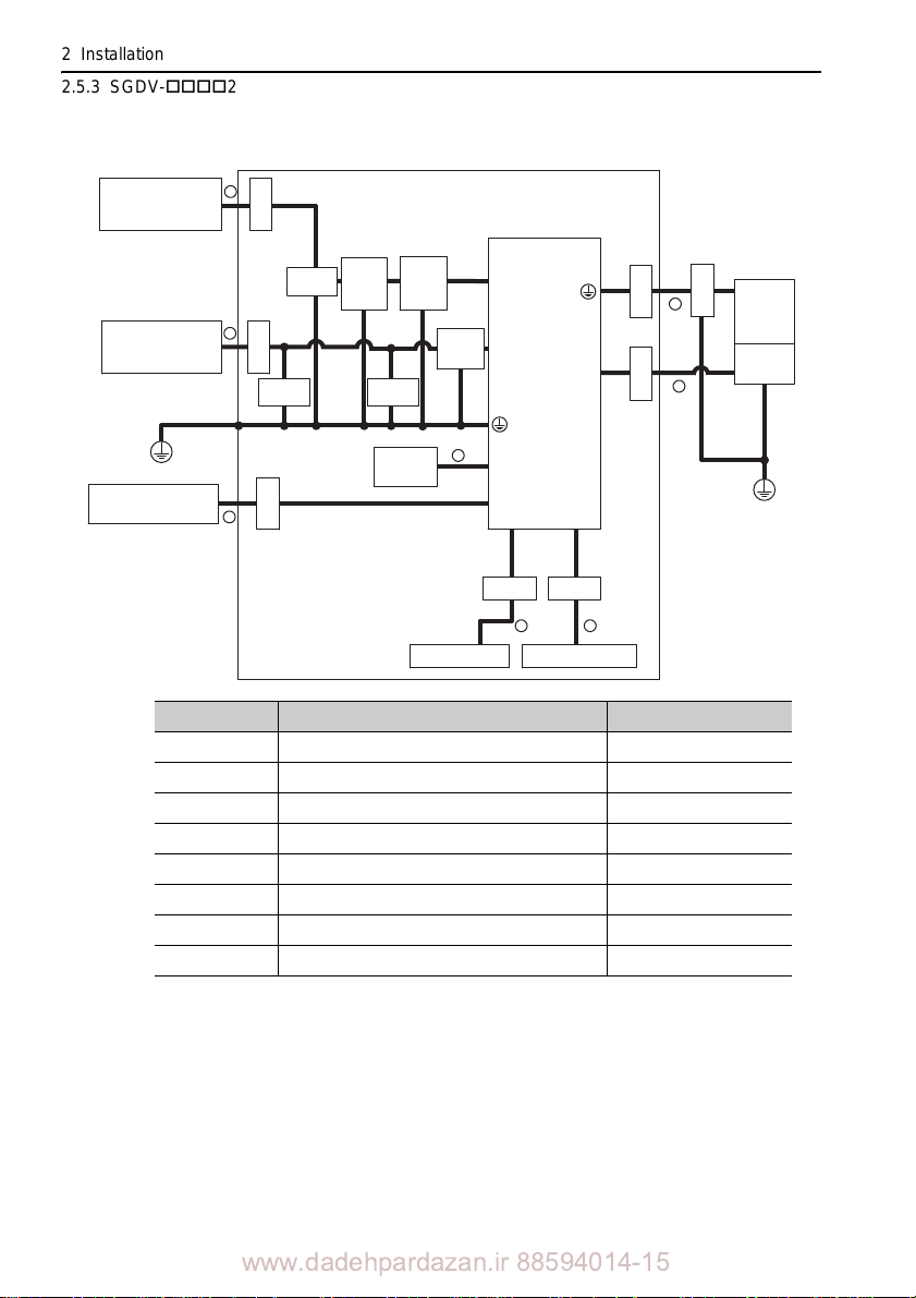
2 Installation
CN2
1
2
3
6
5
8
7
4
U, V, W
L1, L2, L3
B1, B2
24 V,
0 V
CN1
PE
PE
CN8
CN6A, CN6B
MECHATROLINK-III
controller
SERVOPACK
Safety unit
Linear
scale
Linear
servomotor
Power supply:
Single-phase
200 VAC
Power supply:
Three-phase
400 VAC
Shield box
Clamp
Clamp
Clamp
Clamp
Clamp
Noise
filter*
3
Regenerative
resistor unit
Surge
absorber
Surge
absorber
Surge
absorber
Noise
filter*
2
Control
power
supply
24 VDC*
1
Clamp
Clamp Clamp
Host controller
2.5.3 SGDV-25 (M-III Model)
Three-phase 400 V, SGDV-260D25A
2-60
Symbol Cable Name Specification
I/O signal cable Shield cable
Cable for safety unit Shield cable
Linear servomotor main circuit cable Shield cable
Linear scale connection cables Shield cable
Control power cable Shield cable
Main circuit cable Shield cable
Regenerative resistor unit cable Non-shield cable
MECHATROLINK-III communication cable Shield cable
Products that have received CE marking are recommended for the 24 VDC power supply.
Install the following noise filter on the power
line between the single-phase 200 V power
supply and the 24 VDC power supply.
Model number: FN2070-6/07 (SCHAFFNER)
For more information on this filter, refer to
42)
www.dadehpardazan.ir 88594014-15
-V Series Product Catalog. (KAEP S8 00000
Page 84
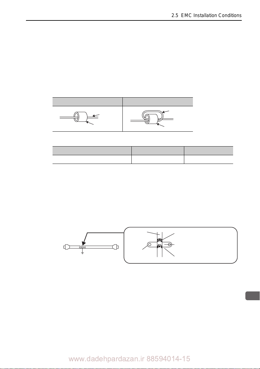
2.5 EMC Installation Conditions
2
Installation
Cable
Ferrite core
Cable
Ferrite core
Host controller side
Ground plate
Cable
Cable
clamp
Shield (cable sheath stripped)
Fix and ground the cable shield
using a piece of conductive metal.
Remove paint on mounting surface.
2.5.4 SGDV-E5A (Command Option Attachable Type)
For SER VOPACKs of command option attachable type, EMC installation conditions
may differ depending on the attached option module. For details, refer to the user’s
manual for each option module.
2.5.5 Other Precautions
(1) Attachment Methods of Ferrite Cores
One turn Two turn
(2) Recommended Ferrite Core
Cable Name Ferrite Core Model Manufacturer
Linear servomotor main circuit cable ESD-SR-250 NEC TOKIN Corp.
(3) Recommended Noise Filter and Surge Absorber
For more information on recommended noise filters and surge absorbers, refer to -V
Series Product Catalog. (KAEP S800000 42)
(4) Fixing the Cable
Fix and ground the cable shield using a piece of conductive metal.
• Example of Cable Clamp
(5) Shield Box
A shield box, which is a closed metallic enclosure, is effective as reinforced shielding
against electromagnetic interference (EMI) from SERVOPACKs. The structure of the
box should allow the main body, door, and cooling unit to be attached to the ground.
The box opening should be as small as possible.
Note: Do not connect the digital operator and the analog monitor cable to the SERVOPACK
during operations. Connect them only when the machinery is stopped during maintenance.
www.dadehpardazan.ir 88594014-15
2-61
Page 85

2 Installation
2.5.5 Other Precautions
2-62
www.dadehpardazan.ir 88594014-15
Page 86
3
Wiring and Connection
3
Wiring and Connection
This chapter describes how to set up the wiring and connections required for trial
operation.
For more information on the wiring and connection, refer to the following manuals.
• -V Series User's Manual Design and Maintenance Linear Motor/
Analog Voltage and Pulse Train Reference (SIEP S800000 47)
• -V Series User's Manual Design and Maintenanc
MECHATROLINK-II Communications Reference (SIEP S800000 48)
• -V Series User's Manual Design and Maintenanc
MECHATROLINK-III Communications Reference (SIEP S800000 65)
• -V Series User's Manual Design and Maintenance Linear Motor/
Command Option Attachable Type (SIEP S800000 66)
3.1 Precautions for Wiring . . . . . . . . . . . . . . . . . . . . . . . . . . . . . . . . 3-3
3.2 System Configuration Diagram . . . . . . . . . . . . . . . . . . . . . . . . . 3-4
3.2.1 Connecting to SGDV-05 SERVOPACK
(Analog Pulse Model) . . . . . . . . . . . . . . . . . . . . . . . . . . . . . . . . . .3-4
3.2.2 Connecting to SGDV-15 SERVOPACK
(M-II Model)
3.2.3 Connecting to SGDV-25 SERVOPACK
(M-III Model) . . . . . . . . . . . . . . . . . . . . . . . . . . . . . . . . . . . . . . . .3-12
3.2.4 Connecting to SGDV-E5A SERVOPACK
(Command Option Attachable Type) . . . . . . . . . . . . . . . . . . . . .3-16
. . . . . . . . . . . . . . . . . . . . . . . . . . . . . . . . . . . . . . . . . 3-8
3.3 Main Circuit Wiring . . . . . . . . . . . . . . . . . . . . . . . . . . . . . . . . . 3-20
3.3.1 Main Circuit Terminals . . . . . . . . . . . . . . . . . . . . . . . . . . . . . . . .3-20
3.3.2 When Using a Standard Power Supply Input (Single-phase
100 V, Three-phase 200 V, or Three-phase 400 V) . . . . . . . . . . 3-22
3.3.3 When Using the SERVOPACK with a Single-phase
200 V Power Input . . . . . . . . . . . . . . . . . . . . . . . . . . . . . . . . . . .3-27
3.3.4 When Using the SERVOPACK with a DC Power Input . . . . . . .3-30
3.3.5 When Using More Than One SERVOPACK . . . . . . . . . . . . . . . .3-34
3.3.6 General Precautions for Wiring . . . . . . . . . . . . . . . . . . . . . . . . . .3-35
e Linear Motor/
e Linear Motor/
3-1
www.dadehpardazan.ir 88594014-15
Page 87

3 Wiring and Connection
3.3.7 Wiring the Spring Type Main Circuit Terminal Connector . . . . . . 3-36
3.4 Connecting Regenerative Resistors . . . . . . . . . . . . . . . . . . . . .3-38
3.4.1 Connecting Regenerative Resistor . . . . . . . . . . . . . . . . . . . . . . . 3-38
3.4.2 Setting the Regenerative Resistor Capacity . . . . . . . . . . . . . . . . 3-41
3.5 Linear Scale Connections . . . . . . . . . . . . . . . . . . . . . . . . . . . .3-42
3.5.1 Linear Scale Signal (CN2) Names and Functions . . . . . . . . . . . 3-42
3.5.2 Linear Scale Connection Examples . . .
. . . . . . . . . . . . . . . . . . . 3-43
3-2
www.dadehpardazan.ir 88594014-15
Page 88
3
Wiring and Connection
3.1 Precautions for Wiring
3.1 Precautions for Wiring
CAUTION
• Be sure to wire correctly and securely.
Failure to observe this caution may result in motor overrun, injury
• Do not bundle or run the main circuit cables together with
the linear scale connection cables in the same duct. Keep them separated by at
least 30 cm.
Failure to do so may result in malfunction.
• Use shielded twisted-pair wires or multi-co
signal cables and the linear scale connection cables.
• The maximum cable length is 3 m for the I/O signals, 20
tor main circuit, 20 m for serial converter unit, 15 m for the linear scale, 15 m for
the hall sensor, and 10 m for control power supply cables for the SERVOPACK
with a 400-V power supply (+24 V, 0 V).
• Do not touch the power terminals while the charg
power OFF because high voltage may still remain in the SERVOPACK.
Make sure the charge indicator is off first before
• Leakage current may increase depending on the type of noise filter and the
grounding conditions.
When using
one by considering the type of noise filter and the grounding conditions.
For details, contact the manufacturer of the noise filter.
• Incorrect wiring or incorrect voltage applicatio
short-circuit.
The above failures will prevent the holding brak
machine or cause an accident resulting in death or injury.
• Inverting the polarity of the brake signal (/BK), i.e. positive logic, will prevent the
holding
If this setting is absolutely necessary, check the operation and confirm that there
are n
a detector or a breaker for leakage current, select the appropriate
brake from working in case of its signal line disconnection.
o safety problems.
re shielded twisted-p
e indicator is ON af
starting wiring and inspection.
n to the output circuit may
e from working, which may damage the
, or malfunction.
the I/O signal cables or
air wires for I/O
m for the linear servomo-
ter turning
cause
3-3
www.dadehpardazan.ir 88594014-15
Page 89
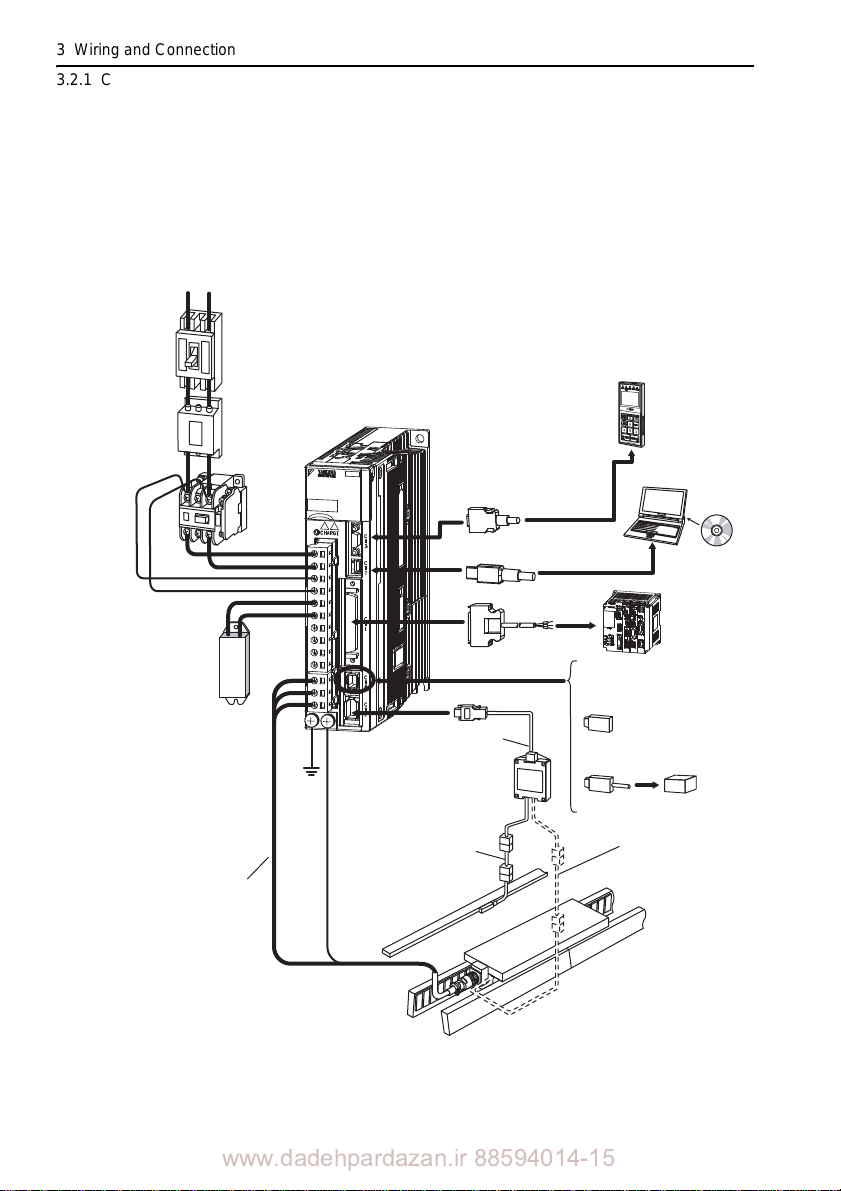
3 Wiring and Connection
SGDV-2R1F01A
100
V
3.2.1 Connecting to SGDV-05 SERVOPACK (Analog Pulse Model)
3.2 System Configuration Diagram
3.2.1 Connecting to SGDV-05 SERVOPACK (Analog
Pulse Model)
(1) SGDV-F05A
Power supply
Single-phase 100 VAC
Molded-case
circuit breaker
(MCCB)
Protects the power supply
line by shutting the
circuit OFF when
overcurrent is
detected.
Noise filter
Used to eliminate
external noise from
the power line.
R T
Magnetic
contactor
Turns the servo
ON and OFF.
Install a surge
absorber.
SGDV-F05A
SERVOPACK
100
SGDV-2R1F01A
Connection cable
for digital operator
Connection cable
for personal computer
Digital
operator
Personal
computer
3-4
Regenerative
resistor*
I/O signal cable
When not using the safety
function, use the SERVOPACK
with the safety function jumper
connector (JZSP-CVH05-E,
provided as an accessory) inserted.
Cable for connecting a
serial converter unit
When using the safety function,
insert a connection cable
specifically for the safety function.
Host controller
Serial converter unit
Safety function
devices
Cable for connecting a
linear scale
Linear servomotor
main circuit cable
Before connecting an external regenerativ e resistor to the SERVOPACK, refer to 3.4 Con-
necting Regenerative Resistors.
Linear scale
(Not included)
Cable for connecting a
hall sensor
Linear servomotor
with core
www.dadehpardazan.ir 88594014-15
Page 90
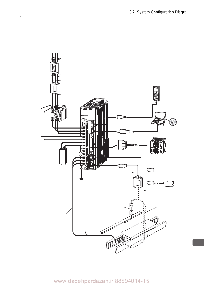
3
Wiring and Connection
R S T
SGDV-A05
SERVOPACK
Power supply
Three-phase 200 VAC
Noise filter
Molded-case
circuit breaker
(MCCB)
Protects the power supply
line by shutting the
circuit OFF when
overcurrent is
detected.
Used to eliminate
external noise from
the power line.
Magnetic
contactor
Turns the servo
ON and OFF.
Install a surge
absorber.
Regenerative
resistor*
When not using the safety
function, use the SERVOPACK
with the safety function jumper
connector (JZSP-CVH05-E,
provided as an accessory) inserted.
When using the safety function,
insert a connection cable
specifically for the safety function.
Safety function
devices
I/O signal cable
Connection cable
for digital operator
Connection cable
for personal computer
Digital
operator
Personal
computer
Host controller
Linear servomotor
main circuit cable
Serial converter unit
Cable for connecting a
serial converter unit
Linear servomotor
with core
Linear scale
(Not included)
Cable for connecting a
hall sensor
Cable for connecting a
linear scale
(2) SGDV-A05 SERVOPACK
Using a Three-phase, 200-V Power Supply
3.2 System Configuration Diagram
Before connecting an external regenerative resistor to the SERVOPACK, refer to 3.4 Con-
necting Regenerative Resistors.
www.dadehpardazan.ir 88594014-15
3-5
Page 91

3 Wiring and Connection
R S T
SGDV-A05
SERVOPACK
Power supply
Single-phase 200 VAC
Noise filter
Molded-case
circuit breaker
(MCCB)
Protects the power supply
line by shutting the
circuit OFF when
overcurrent is
detected.
Used to eliminate
external noise from
the power line.
Magnetic
contactor
Turns the servo
ON and OFF.
Install a surge
absorber.
Regenerative
resistor*
When not using the safety
function, use the SERVOPACK
with the safety function jumper
connector (JZSP-CVH05-E,
provided as an accessory) inserted.
When using the safety function,
insert a connection cable
specifically for the safety function.
Safety function
devices
I/O signal cable
Connection cable
for digital operator
Connection cable
for personal computer
Digital
operator
Personal
computer
Host controller
Linear servomotor
main circuit cable
Serial converter unit
Cable for connecting a
serial converter unit
Linear servomotor
with core
Linear scale
(Not included)
Cable for connecting a
hall sensor
Cable for connecting a
linear scale
3.2.1 Connecting to SGDV-05 SERVOPACK (Analog Pulse Model)
Using a Single-phase, 200-V Power Supply
The -V Series SER VOPACK for a 200-V power supply input has input specifications for a three-phase power supply, but some models can also be used
phase 200-V power supply. For details, refer to
Maintenance Linear Motor/Analog Voltage and Pulse Train Reference (SIEP
S800000 47).
with a single-
-V Series User's Manual Design and
3-6
Before connecting an external regenerativ e resistor to the SERVOPACK, refer to 3.4 Con-
necting Regenerative Resistors.
www.dadehpardazan.ir 88594014-15
Page 92
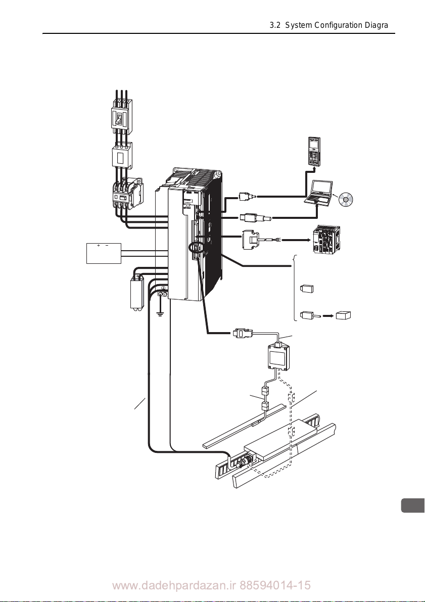
3
Wiring and Connection
(3) SGDV-D05A
Power supply
Three-phase 400 VAC
R S T
Molded-case
circuit breaker
(MCCB)
Protects the power supply
line by shutting the
circuit OFF when
overcurrent is
detected.
Noise filter
Used to eliminate
external noise from
the power line.
24 VDC
power supply
Regenerative
resistor*
Magnetic
contactor
Turns the servo
ON and OFF.
Install a surge
absorber.
∗1
2
SGDV-D05A
SERVOPACK
3.2 System Configuration Diagram
Connection cable
for digital operator
Connection cable
for personal computer
I/O signal cable
Digital
operator
Personal
computer
Host controller
When not using the safety
function, use the SERVOPACK
with the safety function jumper
connector (JZSP-CVH05-E,
provided as an accessory) inserted.
When using the safety function,
insert a connection cable
specifically for the safety function.
Linear servomotor
main circuit cable
Use a 24 VDC power supply with double insulation or reinforced insulation. (The power
Before connecting an external regenerative
Cable for connecting a
linear scale
Linear scale
(Not included)
supply is not included)
resisto
r to the SERVOP ACK, ref er to 3.4 Con -
necting Regenerative Resistors.
www.dadehpardazan.ir 88594014-15
Safety function devices
Cable for connecting a
serial converter unit
Serial converter unit
Cable for connecting a
hall sensor
Linear servomotor
with core
3-7
Page 93
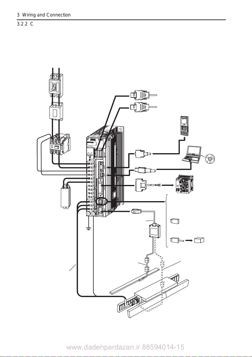
3 Wiring and Connection
R T
Connect to the
MECHATROLINK-II
SGDV-F15A
SERVOPACK
Power supply
Single-phase 100 VAC
Noise filter
Molded-case
circuit breaker
(MCCB)
Protects the power
supply line by shutting
the circuit OFF when
overcurrent is detected.
Used to eliminate
external noise from
the power line.
Magnetic
contactor
Turns the servo
ON and OFF.
Install a surge
absorber.
Regenerative
resistor*
When not using the safety
function, use the SERVOPACK
with the safety function jumper
connector (JZSP-CVH05-E,
provided as an accessory)
inserted.
When using the safety function,
insert a connection cable
specifically for the safety function.
Safety function
devices
I/O signal cable
Connection cable
for digital operator
Connection cable
for personal computer
Digital
operator
Personal
computer
Host controller
Linear servomotor
main circuit cable
Serial converter unit
Cable for connecting a
serial converter unit
Linear servomotor
with core
Linear scale
(Not included)
Cable for connecting a
hall sensor
Cable for connecting a
linear scale
3.2.2 Connecting to SGDV-15 SERVOPACK (M-II Model)
3.2.2 Connecting to SGDV-15 SERVOPACK (M-II Model)
(1) SGDV-F15A
3-8
Before connecting an external regenerativ e resistor to the SERVOPACK, refer to 3.4 Con-
necting Regenerative Resistors.
www.dadehpardazan.ir 88594014-15
Page 94
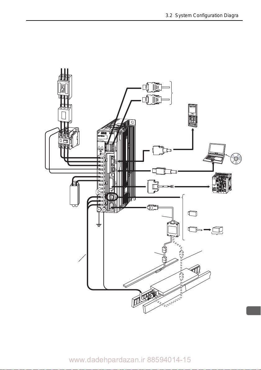
3
Wiring and Connection
R S T
Connect to the
MECHATROLINK-II
SGDV-A15
SERVOPACK
Power supply
Three-phase 200 VAC
Noise filter
Molded-case
circuit breaker
(MCCB)
Protects the power
supply line by shutting
the circuit OFF when
overcurrent is detected.
Used to eliminate
external noise from
the power line.
Magnetic
contactor
Turns the servo
ON and OFF.
Install a surge
absorber.
Regenerative
resistor*
When not using the safety function,
use the SERVOPACK with the safety
function jumper connector
(JZSP-CVH05-E, provided as
an accessory) inserted.
When using the safety function,
insert a connection cable
specifically for the safety function.
Safety function
devices
I/O signal cable
Connection cable
for digital operator
Connection cable
for personal computer
Digital
operator
Personal
computer
Host controller
Linear servomotor
main circuit cable
Serial converter unit
Cable for connecting a
serial converter unit
Linear servomotor
with core
Linear scale
(Not included)
Cable for connecting a
hall sensor
Cable for connecting a
linear scale
(2) SGDV-A15
Using a Three-phase, 200-V Power Supply
3.2 System Configuration Diagram
Before connecting an external regenerative resistor to the SERVOPACK, refer to 3.4 Con-
necting Regenerative Resistors.
www.dadehpardazan.ir 88594014-15
3-9
Page 95
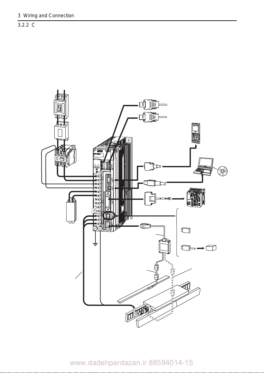
3 Wiring and Connection
3.2.2 Connecting to SGDV-15 SERVOPACK (M-II Model)
Using a Single-phase, 200-V Power Supply
The -V Series SER VOPACK for a 200-V power supply input has input specifications for a three-phase power supply, but some models can also be used
phase 200-V power supply. For details, refer to
Maintenance Linear Motor/MECHATROLINK-II Communications Reference (SIEP
S800000 48).
Power supply
Single-phase 200 VAC
Molded-case
circuit breaker
(MCCB)
Protects the power supply
line by shutting the
circuit OFF when
overcurrent is
detected.
Noise filter
Used to eliminate
external noise from
the power line.
R T
SGDV-A15
SERVOPACK
Magnetic
contactor
Turns the servo
ON and OFF.
Install a surge
absorber.
-V Series User's Manual Design and
Connection cable
for digital operator
Connection cable
for personal computer
I/O signal cable
Connect to the
MECHATROLINK-II
Host controller
with a single-
Digital
operator
Personal
computer
3-10
Regenerative
resistor*
Cable for connecting a
serial converter unit
Serial converter unit
Cable for connecting a
linear scale
Linear servomotor
main circuit cable
Before connecting an external regenerativ e resistor to the SERVOPACK, refer to 3.4 Con-
necting Regenerative Resistors.
Linear scale
(Not included)
When not using the safety
function, use the SERVOPACK
with the safety function jumper
connector (JZSP-CVH05-E,
provided as an accessory)
inserted.
When using the safety function,
insert a connection cable
specifically for the safety function.
Safety function
devices
Cable for connecting a
hall sensor
Linear servomotor
with core
www.dadehpardazan.ir 88594014-15
Page 96
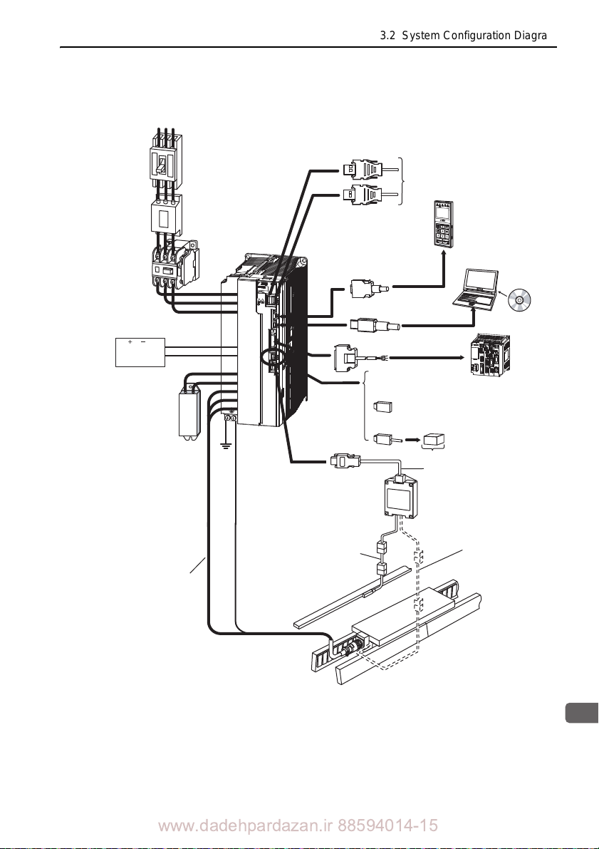
3
Wiring and Connection
R S T
24 VDC
power supply
∗
1
Connect to the
MECHATROLINK-II
SGDV-D15A
SERVOPACK
Power supply
Three-phase 400 VAC
Noise filter
Molded-case
circuit breaker
(MCCB)
Protects the power supply
line by shutting the
circuit OFF when
overcurrent is
detected.
Used to eliminate
external noise from
the power line.
Magnetic
contactor
Turns the servo
ON and OFF.
Install a surge
absorber.
When not using the safety
function, use the SERVOPACK with
the safety function jumper connector
(JZSP-CVH05-E, provided as an
accessory) inserted.
When using the safety function,
insert a connection cable
specifically for the safety function.
Safety function devices
I/O signal cable
Connection cable
for digital operator
Connection cable
for personal computer
Digital
operator
Personal
computer
Host controller
Regenerative
resistor
*
2
Linear servomotor
main circuit cable
Serial converter unit
Cable for connecting a
serial converter unit
Linear servomotor
with core
Linear scale
(Not included)
Cable for connecting a
hall sensor
Cable for connecting a
linear scale
(3) SGDV-D15A
3.2 System Configuration Diagram
Use a 24 VDC power supply with double insulation or reinforced insulation. (The power
Before connecting an external regenerative
supply is not included)
resisto
r to the SERVOP ACK, ref er to 3.4 Con -
necting Regenerative Resistors.
www.dadehpardazan.ir 88594014-15
3-11
Page 97
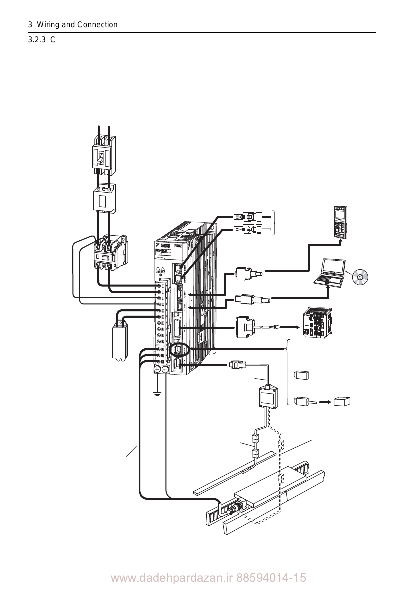
3 Wiring and Connection
R T
Regenerative
resistor*
Noise filter
Molded-case
circuit breaker
(MCCB)
Magnetic contacator
I/O signal cable
SGDV-F25A
SERVOPACK
Power supply
Single-phase 100 VAC
Protects the power supply
line by shutting the circuit
OFF when overcurrent
is detected.
Used to eliminate
external noise from
the power line.
Turns the servo
ON and OFF.
Install a surge
absorber.
Personal
computer
Connection cable
for personal computer
Digital
operator
When not using the safety
function, use the SERVOPACK
with the safety function jumper
connector (JZSP-CVH05-E,
provided as an accessory)
inserted.
When using the safety function,
insert a connection cable
specially for the safety function.
Safety function
devices
Connection cable
for digital operator
Host controller
Connect to the
MECHATROLINK-III
Linear servomotor
main circuit cable
Serial converter unit
Cable for connecting a
serial converter unit
Linear servomotor
with core
Linear scale
(Not included)
Cable for connecting a
hall sensor
Cable for connecting a
linear scale
3.2.3 Connecting to SGDV-25 SERVOPACK (M-III Model)
3.2.3 Connecting to SGDV-25 SERVOPACK (M-III
Model)
(1) SGDV-F25A
3-12
Before connecting an external regenerativ e resistor to the SERVOPACK, refer to 3.4 Con-
necting Regenerative Resistors.
www.dadehpardazan.ir 88594014-15
Page 98
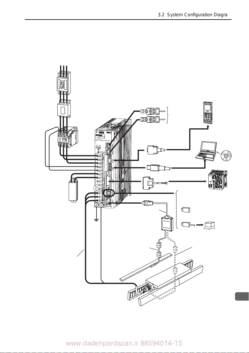
3
Wiring and Connection
(2) SGDV-A25
Using a Three-phase, 200-V Power Supply
Power supply
Single-phase 200 VAC
R S T
Molded-case
circuit breaker
(MCCB)
Protcts the power supply
line by shutting the
circuit OFF when
overcurrent is detected.
3.2 System Configuration Diagram
Noise filter
Used to eliminate
external noise from
the power line.
Magnetic contactor
Turns the servo
ON and OFF.
Install a surge
absorber.
Regenerative
resistor*
Linear servomotor
main circuit cable
SGDV-A25
SERVOPACK
Cable for connecting a
serial converter unit
Cable for connecting a
linear scale
Linear scale
(Not included)
Connection cable
for digital operator
Connection cable
for personal computer
I/O signal cable
Serial converter unit
Connect to the
MECHATROLINK-III
When not using the safety
function, use the SERVOPACK
with the safety function jumper
connector (JZSP-CVH05-E,
provided as an accessory)
inserted.
When using the safety function,
insert a connection cable
specifically for the safety function.
Cable for connecting a
hall sensor
Digital
operator
Personal
computer
Host controller
Safety function
devices
Before connecting an external regenerative resistor to the SERVOPACK, refer to 3.4 Con-
necting Regenerative Resistors.
www.dadehpardazan.ir 88594014-15
Linear servomotor
with core
3-13
Page 99
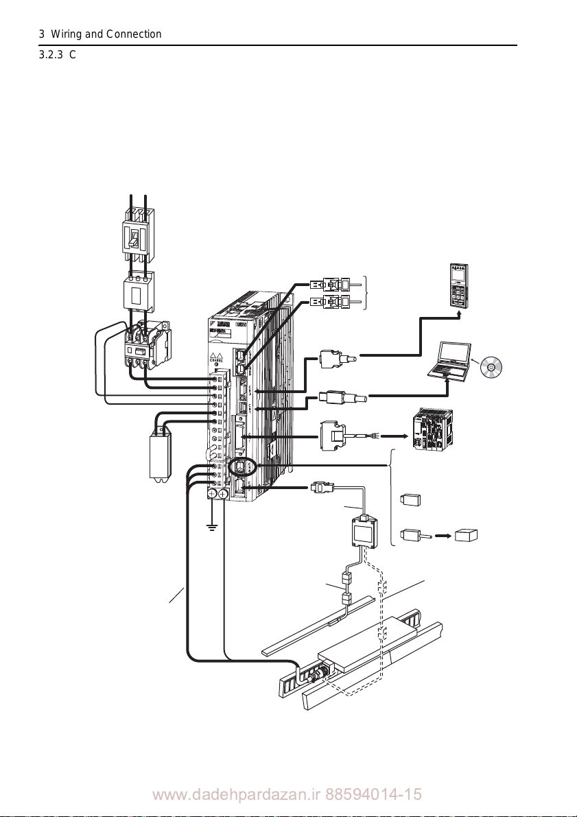
3 Wiring and Connection
R T
Noise filter
Molded-case
circuit breaker
(MCCB)
Magnetic contactor
I/O signal cable
SGDV-A25
SERVOPACK
Power supply
Single-phase 200 VAC
Protcts the power supply
line by shutting the
circuit OFF when
overcurrent is detected.
Used to eliminate
external noise from
the power line.
Turns the servo
ON and OFF.
Install a surge
absorber.
Personal
computer
Connection cable
for personal computer
Digital
operator
When not using the safety
function, use the SERVOPACK
with the safety function jumper
connector (JZSP-CVH05-E,
provided as an accessory)
inserted.
When using the safety function,
insert a connection cable
specifically for the safety function.
Safety function
devices
Connection cable
for digital operator
Host controller
Regenerative
resistor*
Connect to the
MECHATROLINK-III
Linear servomotor
main circuit cable
Serial converter unit
Cable for connecting a
serial converter unit
Linear servomotor
with core
Linear scale
(Not included)
Cable for connecting a
hall sensor
Cable for connecting a
linear scale
3.2.3 Connecting to SGDV-25 SERVOPACK (M-III Model)
Using a Single-phase, 200-V Power Supply
The -V Series SER VOPACK for a 200-V power supply input has input specifications for a three-phase power supply, but some models can also be used
phase 200-V power supply. For details, refer to
Maintenance Linear Motor/MECHATROLINK-III Communications Reference (SIEP
S800000 65).
with a single-
-V Series User's Manual Design and
3-14
Before connecting an external regenerativ e resistor to the SERVOPACK, refer to 3.4 Con-
necting Regenerative Resistors.
www.dadehpardazan.ir 88594014-15
Page 100
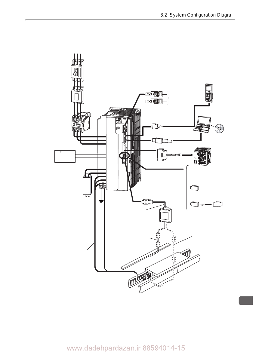
3
Wiring and Connection
24 VDC
power supply
∗
1
Noise filter
Molded-case
circuit breaker
MCCB)
Magnetic
contactor
I/O signal cable
Power supply
Three-phase 400 VAC
R S T
Protects the power
supply line by shutting
the circuit OFF when
overcurrent is
detected.
Used to eliminate
external noise from
the power line.
Turns the servo
ON and OFF.
Install a surge
absorber.
Personal
computer
Connection cable
for personal computer
Digital
operator
Connection cable
for digital operator
When not using the safety
function, use the SERVOPACK
with the safety function jumper
connector (JZSP-CVH05-E,
provided as an accessory)
inserted.
When using the safety function,
insert a connection cable
specifically for the safety function.
Safety function
devices
SGDV-D25A
SERVOPACK
Host controller
Regenerative
resistor*
2
Connect to the
MECHATROLINK-III
Linear servomotor
main circuit cable
Serial converter unit
Cable for connecting a
serial converter unit
Linear servomotor
with core
Linear scale
(Not included)
Cable for connecting a
hall sensor
Cable for connecting a
linear scale
(3) SGDV-D25A
3.2 System Configuration Diagram
Use a 24 VDC power supply with double insulation or reinforced insulation. (The power
Before connecting an external regenerative resisto
supply is not included)
r to the SERVOP ACK, ref er to 3.4 Con -
necting Regenerative Resistors.
www.dadehpardazan.ir 88594014-15
3-15
 Loading...