

Page 1

制動ユニット CDBR-
制動抵抗器ユニット LKEB-
制動ユニット,制動抵抗器ユニット
安川インバータオプション
取扱説明書
BRAKING UNIT CDBRBRAKING RESISTOR UNIT LKEB-
Braking unit,
Braking resistor unit
YASKAWA AC Drive Option
Installation Manual
To properly use the product, read this manual thoroughly and retain
for easy reference, inspection, and maintenance. Ensure the end user
receives this manual.
MANUAL NO. TOBP C720600 00F
製品を安全にお使い頂くために,本書を必ずお読みください。
また,本書をお手元に保管していただくとともに,最終的に本製品をご使用になる
ユーザー様のお手元に確実に届けられるよう,お取り計らい願います。
Phone: 800.894.0412 - Fax: 888.723.4773 - Web: www.clrwtr.com - Email: info@clrwtr.com
Page 2

3
PREFACE
Braking resistor unit and braking unit are used to con-sume regenerative
energy from motor in the braking resistor unit at deceleration and to
improve the transis-tor inverter braking ability.
Before using the braking resistor unit and braking unit, a thorough understanding of this manual is recom-mended. This instruction manual will be
of great help for daily maintenance, inspection and troubleshoot-ing.
Inverters to which the braking resistor unit and braking unit can be connected are of the following series:
• YASKAWA AC Drive 1000 Series
• Varispeed Series
Wiring sequence should shut of f power to the drive when a braking
resistor Overload Relay Trip Contact (Thermal Protector Contact)
output is triggered.
NOTENOTE
Phone: 800.894.0412 - Fax: 888.723.4773 - Web: www.clrwtr.com - Email: info@clrwtr.com
Page 3

4
General Precautions
S Some drawings in this manual are shown with the protective cover or shields
removed, in order to describe with more clarity. Make sure all covers and
shields are replaced before operating this product.
S Since the drawings in this manual are represented examples, some are subject
to differ from delivered products.
S This manual may be modified when necessary because of improvement of the
product, modification or changes in specifications. Such modifications are
denoted by a revised manual No.
S To order a copy of this manual, if your copy has been damaged or lost, contact
your YASKAWA representative.
S YASKAWA is not responsible for any modification of the productmadebythe
user since that will void your guarantee.
Phone: 800.894.0412 - Fax: 888.723.4773 - Web: www.clrwtr.com - Email: info@clrwtr.com
Page 4
5
NOTES FOR SAFE OPERATION
Read this instruction manual thoroughly before installation, operation,
maintenance or inspection of the braking un it and the braking resistor unit. I n this
manual, NOTES FOR SAFE OPERATION are classified as “WARNING” or
“CAUTION.”
Indicates a potentially hazardo u s situation which, if not avoided, could result in
death or serious injury to personnel.
Indicates a potentially hazardous situation which, if not avoided, may result in
minor or moderate injury to personnel and damage to equipment.
It may also be used to alert against unsafe practices.
Even items described in CAUTION may result in a vital accident in some situations. In either case, follow the se important notes.
: These are steps to be taken to insure proper operation.
WARNING
CAUTION
CAUTION
NOTENOTE
Phone: 800.894.0412 - Fax: 888.723.4773 - Web: www.clrwtr.com - Email: info@clrwtr.com
Page 5

Phone: 800.894.0412 - Fax: 888.723.4773 - Web: www.clrwtr.com - Email: info@clrwtr.com
Page 6

7
WIRING
(Ref. page)
• Only commence wiring after verifying that the power supply is turned OFF.
Failure to observe this warning can result in an electrical shock
or a fire.
27
• High voltage exists at all terminals of braking unit and
braking resistor unit.
Failure to observe this warning can r esult in an elec trical shock.
27
• Wiring should be performed only by qualified personnel.
Failure to observe this warning can result in an electrical shock
or a fire.
27
• Wiring sequence should shut off power to the drive when
a braking resistor Overload Relay Trip Contact (Thermal
Protector Contact) output is triggered.
Failure to observe this warning can result in a fire.
27
• When wiring the emergency stop circuit, check the wiring
thoroughly before operation.
Failure to observe this warning can result in personal injury.
27
• Make sure to ground the ground terminal.
(Ground resistance
200V class: 100Ω. or less, 400V class: 10Ω. or less)
Failure to observe this warning can r esult in an elec trical shock.
27
• Short Circuit Current Rating (SCCR)
Install adequate branch short circuit protection according to applicable
codes. Failure to comply could result in damage to the drive. The device is
suitable for circuits capable of delivering 31,000 RMS symmet-rical
Amperes, 240 Vac maximum (200V Class), 480 V ac maximum (400V Class)
and 575Vac (600V Class) or the SCCR rating of the drive it is connected to,
which ever is greater.
WARNING
Phone: 800.894.0412 - Fax: 888.723.4773 - Web: www.clrwtr.com - Email: info@clrwtr.com
Page 7

8
CAUTION
(Ref. page)
S Verify that the rated voltage of the braking unit and the braking
resistor unit coincides with the AC power supply voltage.
Failure to observe this caution can result in personal injury or a fire.
27
S Do not perform a withstand voltage test of the braking unit and
braking resistor unit.
It may cause semi−conductor elements to be damaged.
27
S Connect braking resistors, braking resistor units, and braking
units as shown in the I/O wiring examples. Use properly rated
wire in accordance with table 2 on page 31.
Otherwise, a fire can occur.
27
S Tighten terminal screws to the specified tightening torque.
Failure to observe this caution can result in a fire.
27
S Be sure to connect braking resistors or braking resistor units
to the braking units.
If neither braking resistor nor braking resistor unit is connected to a
braking unit, the fault contact may instantaneously turn ON when
the power is turned ON, resulting in malfunction of the inverter.
27
Phone: 800.894.0412 - Fax: 888.723.4773 - Web: www.clrwtr.com - Email: info@clrwtr.com
Page 8
9
OPERATION
WARNING
(Ref. page)
S Only turn ON the input power supply after replacing the front
cover. Do not remove the cover while current is flowing.
Failure to observe this warning can result in an electrical shock.
41
CAUTION
(Ref. page)
S Never touch the heatsink or discharging resistor since the
temperature is very high.
Failure to observe this caution can result in harmful burns to the
body.
41
S Do not check signals during operation.
The machine or the inverter may be damaged.
41
S All theconstants of thethebraking unitandthe braking resistor
unit have been preset at the factory. Do not change the
settings unnecessarily.
41
Phone: 800.894.0412 - Fax: 888.723.4773 - Web: www.clrwtr.com - Email: info@clrwtr.com
Page 9
Phone: 800.894.0412 - Fax: 888.723.4773 - Web: www.clrwtr.com - Email: info@clrwtr.com
Page 10
11
CAUTION
(Ref. page)
S The control PC board employs CMOS ICs. Do not touch the
CMOS elements.
They are easily damaged by static electricity.
46
S Do not connect or disconnect wires orconnectorswhilepower
is applied to the circuit.
Failure to observe this caution can result in personal injury.
46
OTHERS
WARNING
S Never modify the product.
Failure to observe this warning can result in an electrical shock or
personal injury and will invalidate the guarantee.
Phone: 800.894.0412 - Fax: 888.723.4773 - Web: www.clrwtr.com - Email: info@clrwtr.com
Page 11
12
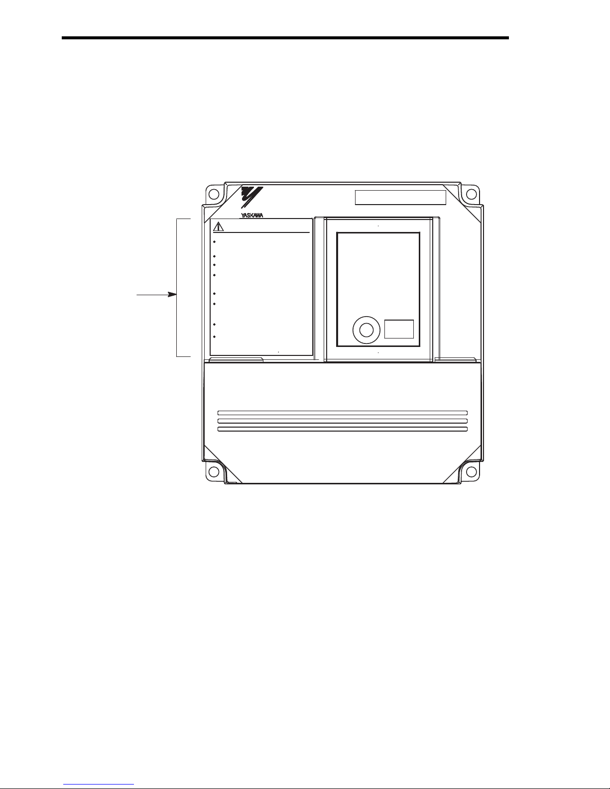
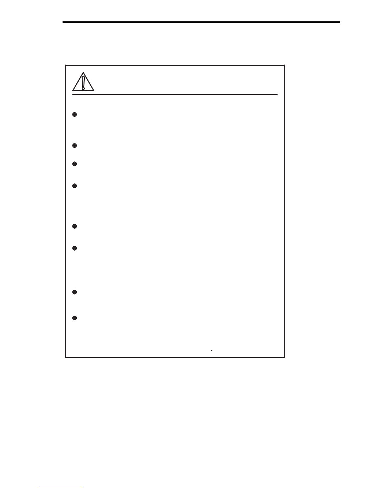
WARNING INDICATION
A warning label is displayed on the front cover of the braking unit, as shown
below. Follow these instructions when handling the braking unit and the braking
resistor unit.
Example of Braking Unit Model CDBR−4045B
Warning
Indication
$4#-+0)70+6
㧹㧻㧰㧱㧸㧦㧯㧰㧮㧾㧙㧠㧜㧠㧡㧮
ޓޓޓޓޓޓ㧠㧜㧜㨂ޓ㧯㧸㧭㧿㧿ޓ㧲㧻㧾ޓ㧠㧡㨗㨃
ߌ߇ޔᗵ㔚ߩ߅ߘࠇ߇ࠅ߹ߔޕ
ᝪ߃ઃߌޔㆇォߩ೨ߦߪᔅߕขᛒ⺑ᦠࠍ⺒ࠎߢޔ
ޓ
ߘߩᜰ␜
ߦᓥߞߡߊߛߐޕ
ᗵ㔚ߩ߅ߘࠇ߇ࠅ߹ߔޕ
ㅢ㔚߮㔚Ḯㆤᢿᓟ㧡ಽએౝߪޔ㕙ࠞࡃࠍ㐿ߌ
ޓ
ߥߢ
ߊߛߐޕ
⏕ታߦធࠍⴕߞߡߊߛߐޕ
㧹㨍㨥ޓ㨏㨍㨡㨟㨑ޓ㨕㨚㨖㨡㨞㨥ޓ㨛㨞㨑㨘㨑㨏㨠㨞㨕㨏ޓ㨟㨔㨛㨏㨗㧚
㧼㨘㨑㨍㨟㨑ޓ㨒㨛㨘㨘㨛㨣ޓ㨠㨔㨑ޓ㨕㨚㨟㨠㨞㨡㨏㨠㨕㨛㨚㨟ޓ㨕㨚ޓ㨠㨔㨑
ޓ
㨙㨍㨚㨡㨍㨘ޓ㨎㨑㨒㨛㨞㨑ޓ㨕㨚㨟㨠㨍㨘㨘㨍㨠㨕㨛㨚ޓ㨛㨞ޓ㨛㨜㨑㨞㨍㨠㨕㨛㨚㧚
㧰㨕㨟㨏㨛㨚㨚㨑㨏㨠ޓ㨍㨘㨘ޓ㨜㨛㨣㨑㨞ޓ㨎㨑㨒㨛㨞㨑ޓ㨛㨜㨑㨚㨕㨚㨓
ޓ
㨒㨞㨛㨚㨠ޓ㨏㨛㨢㨑㨞ޓ㨛㨒ޓ㨡㨚㨕㨠㧚
㨃㨍㨕㨠ޓ㧡ޓ㨙㨕㨚㨡㨠㨑㨟ޓ㨡㨚㨠㨕㨘ޓ㧰㧯ޓ㧮㨡㨟ޓ㨏㨍㨜㨍㨏㨕㨠㨛㨞㨟
㨐㨕㨟㨏㨔㨍㨞㨓㨑㧚
㨁㨟㨑ޓ㨜㨞㨛㨜㨑㨞ޓ㨓㨞㨛㨡㨚㨐㨕㨚㨓ޓ㨠㨑㨏㨔㨚㨕㨝㨡㨑㨟㧚
㧺㧼㧶㨀㧠㧞㧡㧜㧞㧙㧝㧙㧜
ෂ㒾ޓ㨃㧭㧾㧺㧵㧺㧳
Ἣἴߩ߅ߘࠇ߇ࠅ߹ߔޕ
േᛶ᛫ེߩࠨࡑ࡞࠻࠶ࡊធὐߢ㔚Ḯࠍ
ޓㆤᢿߔࠆࠪࠤࡦࠬࠍ⚵ࠎߢߊߛߐޕ
㧾㨕㨟㨗ޓ㨛㨒ޓ㨒㨕㨞㨑㧚
㨁㨟㨑ޓ㨟㨑㨝㨡㨑㨚㨏㨑㨞ޓ㨠㨛ޓ㨎㨞㨑㨍㨗ޓ㨜㨛㨣㨑㨞ޓ㨟㨡㨜㨜㨘㨥ޓ㨟㨕㨐㨑
ޓ
㨛㨚ޓ㨛㨢㨑㨞㨘㨛㨍㨐ޓ㨞㨑㨘㨍㨥ޓ㨠㨞㨕㨜ޓ㨏㨛㨚㨠㨍㨏㨠ޓ㨛㨒ޓ
ޓ
㨎㨞㨍㨗㨕㨚㨓ޓ㨞㨑㨟㨕㨟㨠㨛㨞㧚
ㅢ㔚೨ߦᧄࠞࡃࠍߪߕߒߡޔ
ࠦࡀࠢ࠲ߩ⸳ቯࠍ߅ߎߥߞߡߐޕ
㧔ขᛒ⺑ᦠෳᾖߩߎߣޕ㧕
UGVVJGEQPPGEVQTU
DGHQTGVWTPKPIVJG
RQYGTQP
5GG+PUVTWEVKQPU
4GOQXGVJKUEQXGTCPF
.KIJVU
YJGP
DTCMKPI
Phone: 800.894.0412 - Fax: 888.723.4773 - Web: www.clrwtr.com - Email: info@clrwtr.com
Page 12
13
Warning Indication
ߌ߇ޔᗵ㔚ߩ߅ߘࠇ߇ࠅ߹ߔޕ
ᝪ߃ઃߌޔㆇォߩ೨ߦߪᔅߕขᛒ⺑ᦠࠍ⺒ࠎߢޔ
ޓ
ߘߩᜰ␜
ߦᓥߞߡߊߛߐޕ
ᗵ㔚ߩ߅ߘࠇ߇ࠅ߹ߔޕ
ㅢ㔚߮㔚Ḯㆤᢿᓟ㧡ಽએౝߪޔ㕙ࠞࡃࠍ
ޓ
㐿ߌߥߢ
ߊߛߐޕ
⏕ታߦធࠍⴕߞߡߊߛߐޕ
㧹㨍㨥ޓ㨏㨍㨡㨟㨑ޓ㨕㨚㨖㨡㨞㨥ޓ㨛㨞㨑㨘㨑㨏㨠㨞㨕㨏ޓ㨟㨔㨛㨏㨗㧚
㧼㨘㨑㨍㨟㨑ޓ㨒㨛㨘㨘㨛㨣ޓ㨠㨔㨑ޓ㨕㨚㨟㨠㨞㨡㨏㨠㨕㨛㨚㨟ޓ㨕㨚ޓ㨠㨔㨑
ޓ
㨙㨍㨚㨡㨍㨘ޓ㨎㨑㨒㨛㨞㨑ޓ㨕㨚㨟㨠㨍㨘㨘㨍㨠㨕㨛㨚ޓ㨛㨞ޓ㨛㨜㨑㨞㨍㨠㨕㨛㨚㧚
㧰㨕㨟㨏㨛㨚㨚㨑㨏㨠ޓ㨍㨘㨘ޓ㨜㨛㨣㨑㨞ޓ㨎㨑㨒㨛㨞㨑ޓ㨛㨜㨑㨚㨕㨚㨓
ޓ
㨒㨞㨛㨚㨠ޓ㨏㨛㨢㨑㨞ޓ㨛㨒ޓ㨡㨚㨕㨠㧚
㨃㨍㨕㨠ޓ㧡ޓ㨙㨕㨚㨡㨠㨑㨟ޓ㨡㨚㨠㨕㨘ޓ㧰㧯ޓ㧮㨡㨟ޓ㨏㨍㨜㨍㨏㨕㨠㨛㨞㨟
㨐㨕㨟㨏㨔㨍㨞㨓㨑㧚
㨁㨟㨑ޓ㨜㨞㨛㨜㨑㨞ޓ㨓㨞㨛㨡㨚㨐㨕㨚㨓ޓ㨠㨑㨏㨔㨚㨕㨝㨡㨑㨟㧚
㧺㧼㧶㨀㧠㧞㧡㧜㧞㧙㧝㧙㧜
ෂ㒾ޓ㨃㧭㧾㧺㧵㧺㧳
Ἣἴߩ߅ߘࠇ߇ࠅ߹ߔޕ
േᛶ᛫ེߩࠨࡑ࡞࠻࠶ࡊធὐߢ㔚Ḯࠍ
ޓㆤᢿߔࠆࠪࠤࡦࠬࠍ⚵ࠎߢߊߛߐޕ
㧾㨕㨟㨗ޓ㨛㨒ޓ㨒㨕㨞㨑㧚
㨁㨟㨑ޓ㨟㨑㨝㨡㨑㨚㨏㨑㨞ޓ㨠㨛ޓ㨎㨞㨑㨍㨗ޓ㨜㨛㨣㨑㨞ޓ㨟㨡㨜㨜㨘㨥ޓ㨟㨕㨐㨑
ޓ
㨛㨚ޓ㨛㨢㨑㨞㨘㨛㨍㨐ޓ㨞㨑㨘㨍㨥ޓ㨠㨞㨕㨜ޓ㨏㨛㨚㨠㨍㨏㨠ޓ㨛㨒
ޓ
ޓ
㨎㨞㨍㨗㨕㨚㨓ޓ㨞㨑㨟㨕㨟㨠㨛㨞㧚
Phone: 800.894.0412 - Fax: 888.723.4773 - Web: www.clrwtr.com - Email: info@clrwtr.com
Page 13

14
CONTENTS
NOTES FOR OPERATION - - - - - - - - - - - - - - - - - - - - - - - - - - - - - - - - - - 5
1 RECEIVING - - - - - - - - - - - - - - - - - - - - - - - - - - - - - - - - - - -15
1.1 NAMEPLATE - - - - - - - - - - - - - - - - - - - - - - - - - - - - - - - - - 15
2 INSTALLATION - - - - - - - - - - - - - - - - - - - - - - - - - - - - - - - -16
2.1 LOCATION - - - - - - - - - - - - - - - - - - - - - - - - - - - - - - - - - - - 16
2.2 INSTALLATION - - - - - - - - - - - - - - - - - - - - - - - - - - - - - - - - 16
2.3 REPLACEMENT OF CONVENTIONAL BRAKING UNITS
WITH NEW UNITS - - - - - - - - - - - - - - - - - - - - - - - - - - - - - 25
3 WIRING - - - - - - - - - - - - - - - - - - - - - - - - - - - - - - - - - - - - -27
3.1 REMOVING AND REPLACING THE COVERS OF
THE BRAKING UNIT (MODELS CDBR-2015B, -2015C,
-2022B, -2022C, -4030B, -4045B) - - - - - - - - - - - - - - - - - - - 27
3.2 SECTION NAMES - - - - - - - - - - - - - - - - - - - - - - - - - - - - - - 28
3.3 CIRCUITS AND WIRING SPECIFICATIONS - - - - - - - - - - - 31
3.4 WIRING PRECAUTIONS - - - - - - - - - - - - - - - - - - - - - - - - - 32
3.5 INTERCONNECTION - - - - - - - - - - - - - - - - - - - - - - - - - - - 33
4 OPERATION - - - - - - - - - - - - - - - - - - - - - - - - - - - - - - - - - -41
4.1 ADJUSTMENT - - - - - - - - - - - - - - - - - - - - - - - - - - - - - - - - 41
4.2 POWER SUPPLY VOLTAGE SELECTION CONNECTOR
SETTING - - - - - - - - - - - - - - - - - - - - - - - - - - - - - - - - - - - - 41
4.3 MASTER/SLAVE SELECTION CONNECTOR SETTING - - 44
4.4 PARALLEL CONNECTION OF BRAKING UNIT - - - - - - - - - 44
4.5 OPERATION - - - - - - - - - - - - - - - - - - - - - - - - - - - - - - - - - - 45
5 TROUBLESHOOTING - - - - - - - - - - - - - - - - - - - - - - - - - - -46
6 SPECIFICATIONS - - - - - - - - - - - - - - - - - - - - - - - - - - - - - -47
6.1 BRAKING UNIT AND BRAKING RESISTOR UNIT
APPLICATION LIST - - - - - - - - - - - - - - - - - - - - - - - - - - - - - 47
6.2 BRAKING UNIT FOR 575V CLASS APPLICATION LIST - - 49
6.3 LIST OF APPLICABLE/NOT APPLICABLE COMBINATIONS
WITH CONVENTIONAL MODELS (VS-616HII/H3,
VS-616GII/G3, VS-676) - - - - - - - - - - - - - - - - - - - - - - - - - - 50
6.4 BRAKING UNIT SPECIFICATIONS - - - - - - - - - - - - - - - - - - 51
6.5 BRAKING RESISTOR UNIT SPECIFICATIONS - - - - - - - - - 52
6.6 MODELS AND CODE NOS. OF BRAKING UNIT AND
BRAKING RESISTOR UNIT - - - - - - - - - - - - - - - - - - - - - - - 53
Phone: 800.894.0412 - Fax: 888.723.4773 - Web: www.clrwtr.com - Email: info@clrwtr.com
Page 14
1 RECEIVING
15
1 RECEIVING
The braking resistor unit and braking unit have been put through severe tests at
the factory before shipment. After unpacking, however, check and see the following. If any malfunctions are found, contact your YASKAWA representative.
• Their nameplate data meet your requirements.
• They have sustained no damage while in transit.
• Fastening bolts and screws are not loose.
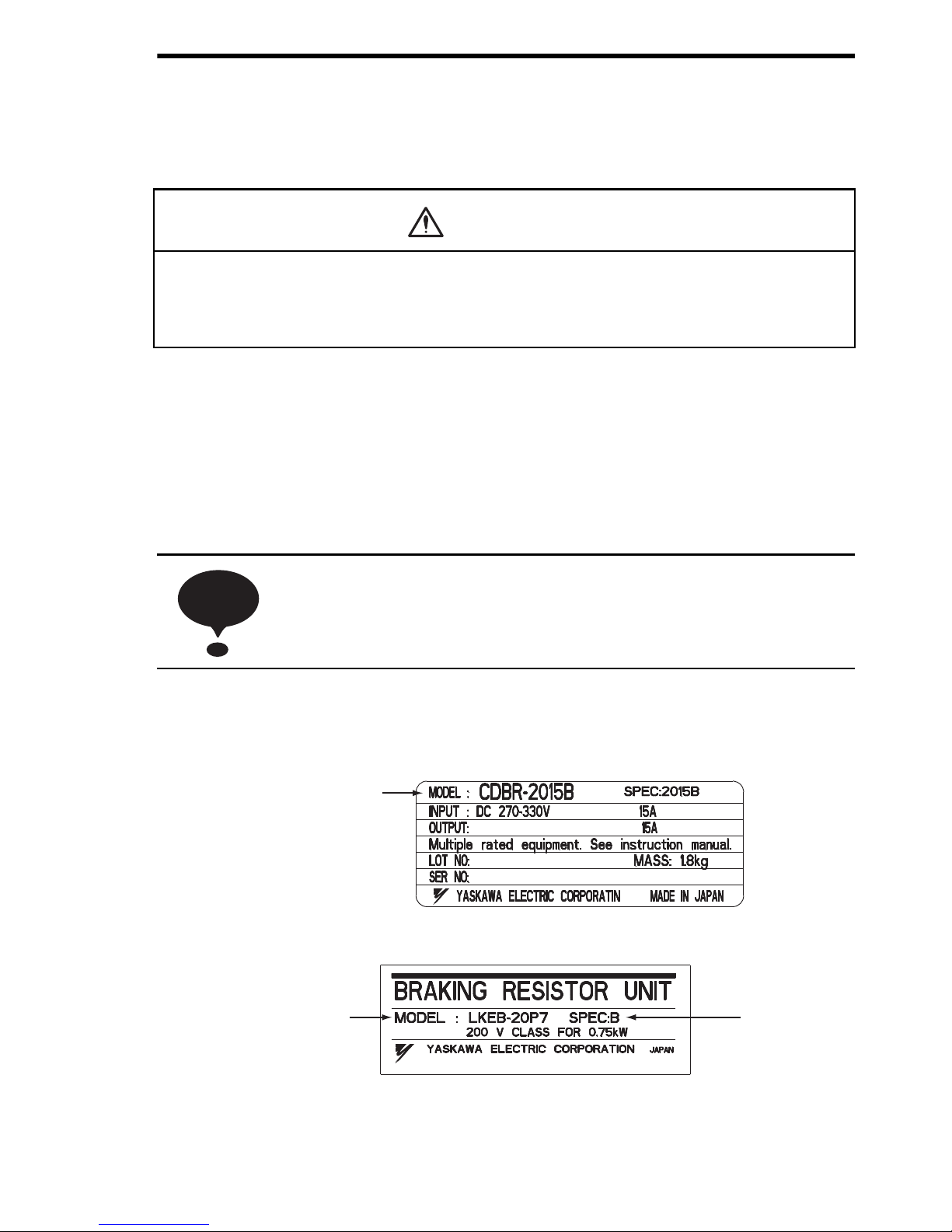
1.1 NAMEPLATE
(1) NAMEPLATE INFORMATION (BRAKING UNIT)
(2) NAMEPLATE INFORMATION (BRAKING RESISTER UNIT)
• Do not install and attempt to use a braking resistor or braking resistor unit If there are any damaged or missing components.
Failure to comply can result in personal injury.
For long term storage, the unit should be kept in a clean area
indoors.
CAUTION
NOTENOTE
Braking Unit
Model Number
Design
Revision
Order
Braking Resistor
Unit Model Number
Phone: 800.894.0412 - Fax: 888.723.4773 - Web: www.clrwtr.com - Email: info@clrwtr.com
Page 15

16
2 INSTALLATION
2.1 LOCATION
If the units are temporarily stored or machine stops for an extended length of
time, the following precautions should be taken. Store the units at pollution level
2 or less (UL standard) and under the following conditions.
• Free from rainfall and drops of water.
• Clean and dry.
• Free from corrosive gases and liquids.
• Free from dirt and dust.
• Ambient temperature: 14 to 104°F, 10 to 40°C.
• Humidity: 90% RH or less (no condensation)
• Free from vibration.
2.2 INSTALLATION
For full use of the braking resistor unit or braking unit functions, install the units
at pollution level 2 or less (UL standard) and in a location to satisfy the following
conditions:
Figs. 1 to 8 show the external dimensions and the spaces from the periphery.
• Provide the spaces shown in Figs. 1 to 8 between the units and the
periphery.
• Since the braking resistor unit generates heat, provide sufficient
spaces from devices which are weak against heat.
• Install the units at such locations that all requirements described in
Par. 2.1 “LOCATION” are satisfied.
Phone: 800.894.0412 - Fax: 888.723.4773 - Web: www.clrwtr.com - Email: info@clrwtr.com
Page 16
2 INSTALLATION
17
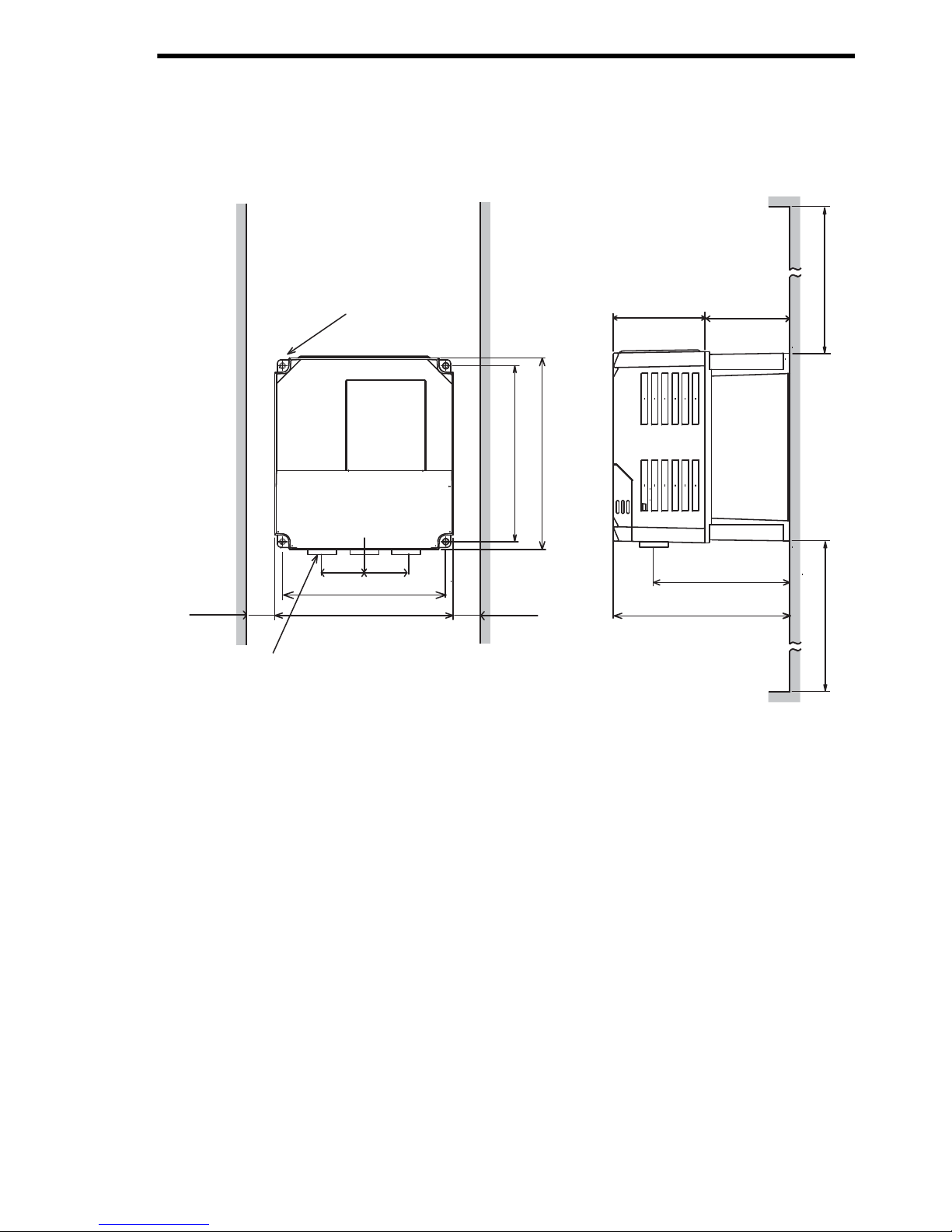
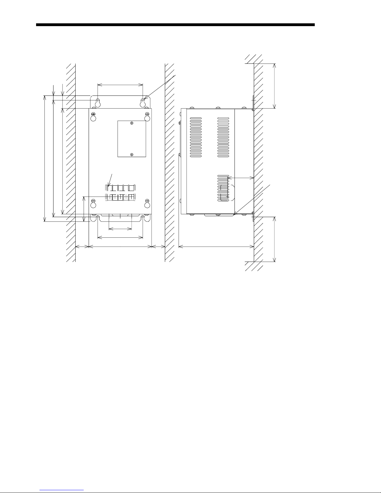
• Install the units in the directions shown in Figs. 1 to 8. There will be
no problem if they are installed vertically.
Fig. 1 Braking Unit Dimensions in inches (mm) CDBR-2015B, -2015C,
-2022B,-2022C,-4030B, -4045B
4−M4 MTG HOLE
1.5 (38) 1.5 (38)
1.18 (30)
OR MORE
3−LEAD WIRE OUTLET
[0.87 (20) DIA RUBBER BUSH]
5.04 (128)
5.51 (140)
2.83 (72)
2.73 (66.5)
4.51 (114.5)
5.45 (138.5)
1.18 (30)
OR MORE
5.43 (138)
5.91 (150)
3.94 (100) OR MORE
3.94 (100) OR MORE
Phone: 800.894.0412 - Fax: 888.723.4773 - Web: www.clrwtr.com - Email: info@clrwtr.com
Page 17
18
6.57 (167)
3.94 (100)
OR MORE
5.51 (140)
3.94 (100)
1.97 (50)
1.18 (30)
OR MORE
(58.5)
2.19 (55.5)
11.02 (280)
10.23 (260)
9.25 (235)
0.39 (10)
1.14 (29)
3.94 (100)
MAIN CIRCUIT
TERMINAL M4
3−LEAD WIRE
OUTLET
1.10 (28) DIA
RUBBER BUSH
4−M6
MTG HOLE
2.30
1.18 (30)
OR MORE
3.94 (100)
OR MORE
Fig. 2 Braking Unit Dimensions in inches (mm) CDBR−5037B
Phone: 800.894.0412 - Fax: 888.723.4773 - Web: www.clrwtr.com - Email: info@clrwtr.com
Page 18

2 INSTALLATION
19
Fig. 3 Braking Unit Dimensions in inches (mm) CDBR-2045B
5.51 (140)
(59)
7.09 (180)
4.37 (111)
6.14 (156)
7.87 (200)
3.86 (98)
3.94 (100)
2.95 (75)
12.48 (317)
13.78 (350)
14.57 (370)
1.44 (36.5)
0.47 (12)
5.51 (140)
MAIN CIRCUIT
TERMINAL M5
2−LEAD WIRE OUTLET
1.38 (35) DIA RUBBER
BUSH
4−M6
MTG HOLE
3.94 (100)
OR MORE
WIRE OUTLET 1.10 (28)
DIA RUBBER BUSH
3.94 (100)
OR MORE
2.32
1.97 (50)
1.18 (30)
OR MORE
1.18 (30)
OR MORE
Phone: 800.894.0412 - Fax: 888.723.4773 - Web: www.clrwtr.com - Email: info@clrwtr.com
Page 19

20
MAIN CIRCUIT
TERMINAL M6
2−LEAD WIRE OUTLET
1.38 (35) DIA RUBBER
BUSH
4−M6
MTG HOLE
3.94 (100)
OR MORE
WIRE OUTLET 1.10 (28)
DIA RUBBER BUSH
3.94 (100)
OR MORE
12.48 (317)
13.78 (350)
14.57 (370)
1.44 (36.5)
0.47 (12)
3.94 (100)
2.87 (73)
5.51 (140)
5.51 (140)
(59)
7.09 (180)
2.32
1.97 (50)
1.18 (30)
OR MORE
1.18 (30)
OR MORE
4.37 (111)
6.14 (156)
7.87 (200)
4.09
(104)
Fig. 4 Braking Unit Dimensions in inches (mm) CDBR−2110B
Phone: 800.894.0412 - Fax: 888.723.4773 - Web: www.clrwtr.com - Email: info@clrwtr.com
Page 20

21
MAIN CIRCUIT
TERMINAL M5
4−M6
MTG HOLE
1.44 (36.5)
0.35 (9)
7.09 (180)
12.48 (317)
13.98 (355)
14.57 (370)
5.45 (138.5)
2.95 (75)
8.66 (220)
(68.5)
7.09 (180)
2.70
1.97 (50)
1.18 (30)
OR MORE
1.18 (30)
OR MORE
2−LEAD WIRE OUTLET
1.38 (35) DIA RUBBER
BUSH
WIRE OUTLET 1.10 (28)
DIA RUBBER BUSH
3.94 (100)
OR MORE
4.37 (111)
6.14 (156)
7.87 (200)
3.94 (100)
OR MORE
3.86 (98)
Fig. 5 Braking Unit Dimensions in inches (mm) CDBR−4090B, −5110B
2.INSTALLATION
Phone: 800.894.0412 - Fax: 888.723.4773 - Web: www.clrwtr.com - Email: info@clrwtr.com
Page 21

22
MAIN CIRCUIT
TERMINAL M6
4−M6
MTG HOLE
1.44 (36.5)
0.35 (9)
8.27 (210)
12.48 (317)
13.98 (355)
14.57 (370)
2.76 (70)
6.16 (156.5)
8.27 (210)
4.67 (118.5)
1.97 (50)
1.18 (30)
OR MORE
9.84 (250)
1.18 (30)
OR MORE
2−LEAD WIRE OUTLET
1.38 (35) DIA RUBBER
BUSH
WIRE OUTLET 1.10 (28)
DIA RUBBER BUSH
3.94 (100)
OR MORE
4.37 (111)
6.14 (156)
7.87 (200)
3.94 (100)
OR MORE
4.09
(104)
Fig. 6 Braking Unit Dimensions in inches (mm) CDBR−4220B, −5300B
Phone: 800.894.0412 - Fax: 888.723.4773 - Web: www.clrwtr.com - Email: info@clrwtr.com
Page 22

2 INSTALLATION
23
Fig. 7 Braking Resistor Unit Dimensions in inches (mm) [for 0.5 to 10HP (0.4 to
7.5kW)]
a
b
b
Braking Resistor
Unit Model
(LKEB-)
Dimensions in inches (mm)
ABCDE
20P7 4.13 (105) 10.83 (275) 1.97 (50) 10.24 (260) M5
21P5 5.12 (130) 13.78 (350) 2.95 (75) 13.19 (335) M5
22P2 5.12 (130) 13.78 (350) 2.95 (75) 13.19 (335) M5
23P7 5.12 (130) 13.78 (350) 2.95 (75) 13.19 (335) M5
25P5 9.84 (250) 13.78 (350) 7.87 (200) 13.19 (335) M6
27P5 9.84 (250) 13.78 (350) 7.87 (200) 13.19 (335) M6
40P7 4.13 (105) 10.83 (275) 1.97 (50) 10.24 (260) M5
41P5 5.12 (130) 13.78 (350) 2.95 (75) 13.19 (335) M5
42P2 5.12 (130) 13.78 (350) 2.95 (75) 13.19 (335) M5
43P7 5.12 (130) 13.78 (350) 2.95 (75) 13.19 (335) M5
45P5 9.84 (250) 13.78 (350) 7.87 (200) 13.19 (335) M6
47P5 9.84 (250) 13.78 (350) 7.87 (200) 13.19 (335) M6
Phone: 800.894.0412 - Fax: 888.723.4773 - Web: www.clrwtr.com - Email: info@clrwtr.com
Page 23

24
Fig. 8 Braking Resistor Unit Dimensions in inches (mm) [for 15 to 60HP (11 to
45kW)]
Braking Resistor
Unit Model
(LKEB-)
Dimensions in inches (mm)
ABCDE
2011 10.48 (266) 21.38 (543) 9.69 (246) 13.39 (340) M8
2015 14.02 (356) 21.38 (543) 13.23 (336) 13.39 (340) M8
2018 17.56 (446) 21.38 (543) 16.77 (426) 13.39 (340) M8
2022 17.56 (446) 21.38 (543) 16.77 (426) 13.39 (340) M8
4011 13.78 (350) 16.22 (412) 12.99 (330) 12.80 (325) M6
4015 13.78 (350) 16.22 (412) 12.99 (330) 12.80 (325) M6
4018 17.56 (446) 21.38 (543) 16.77 (426) 13.39 (340) M8
4022 17.56 (446) 21.38 (543) 16.77 (426) 13.39 (340) M8
4030 14.02 (356) 37.64 (956) 13.23 (336) 29.13 (740) M8
4037 17.56 (446) 37.64 (956) 16.77 (426) 29.13 (740) M8
4045 17.56 (446) 37.64 (956) 16.77 (426) 29.13 (740) M8
Phone: 800.894.0412 - Fax: 888.723.4773 - Web: www.clrwtr.com - Email: info@clrwtr.com
Page 24

2 INSTALLATION
25
2.3 REPLACEMENT OF CONVENTIONAL BRAKING
UNITS WITH NEW UNITS
T o replace conventional braking units (mod els CDBR-2015, -2022, -4030, -4045)
with new units (CDBR-2015B, -2015C, -2022B, -2022C, -4030B, -4045B), an
exclusive-use attachment is required. Contact your YASKAWA representative.
Fig. 9 Mounting Dimensions of Attachment in inches (mm)
0.39
(10)
0.28(7)
3.94 (100)
11.02 (280)
5.51 (140)
10.24 (260)
ATTACHMENT
5.45 (138.5)
0.39 (10)
0.98
(25)
5.91 (150)
4.13 (105)
4−M6 MTG HOLE
Code No.: DACT32732−AD
3.94 (100)
0.79
(20)
0.28(7)
0.79
(20)
Phone: 800.894.0412 - Fax: 888.723.4773 - Web: www.clrwtr.com - Email: info@clrwtr.com
Page 25

26
The main circuit terminal symbols are dif ferent between conventional models and
new models. Refer to the following table.
Table 1 Main Circuit Terminal Symbols
Conventional Models
Example: CDBR-2015
New Models
Example: CDBR-2015B,
-2015C
N
P
P
0
0
B
0
Phone: 800.894.0412 - Fax: 888.723.4773 - Web: www.clrwtr.com - Email: info@clrwtr.com
Page 26

3 WIRING
27
3 WIRING
3.1 REMOVING AND REPLACING THE COVERS OF
THE BRAKING UNIT (MODELS CDBR-2015B,
-2015C, -2022B, -2022C,-4030B, -4045B)
(1) Romoving and Replacing the Terminal Cover
For removing, grasp the terminal cover at c on borh sides and then lift in
the direciton of d. For replacing, reverse the method.
(2) Removing and Replacing the lndicating Cover
Remove the terminal cover first. Push down on the lever in the direction of
c and lift the cover in the direction of d. For replacing, reverse the
method.
Terminal
Cover
Indicating Cover
Lever
Phone: 800.894.0412 - Fax: 888.723.4773 - Web: www.clrwtr.com - Email: info@clrwtr.com
Page 27

28
3.2 SECTION NAMES
Figs. 10, 11 and 12 show appearance and each section name of braking unit and
braking resistor unit respectively.
Thermal overload relay protects th e braking resistor unit for models LKEB-20P7
to -27P5 and -40P7 to -4015. Thermal protector protects the braking resistor unit
for models LKEB-2011 to -2022 and -4018 to -4045.
Fig. 10 Braking Resistor Unit Model CDBR-2015B (Terminal Cover and Indicat-
ing Cover Removed)
Remove the label on the terminal block before using the braking
unit.
/1&'.%&$4$
8%.#55(14M9
$4#-+0)70+6
ߌ߇ޔᗵ㔚ߩ߅ߘࠇ߇ࠅ߹ߔޕ
ᝪ߃ઃߌޔㆇォߩ೨ߦߪᔅߕขᛒ⺑ᦠࠍ⺒ࠎߢޔߘߩᜰ␜
ޓߦᓥߞߡߊߛߐޕ
ᗵ㔚ߩ߅ߘࠇ߇ࠅ߹ߔޕ
ㅢ㔚߮㔚Ḯㆤᢿᓟ㧡ಽએౝߪޔ㕙ࠞࡃࠍ㐿ߌߥߢ
ޓߊߛߐޕ
⏕ታߦធࠍⴕߞߡߊߛߐޕ
㧹㨍㨥ޓ㨏㨍㨡㨟㨑ޓ㨕㨚㨖㨡㨞㨥ޓ㨛㨞
㨑㨘㨑㨏㨠㨞㨕㨏ޓ㨟㨔㨛㨏㨗㧚
㧼㨘㨑㨍㨟㨑ޓ㨒㨛㨘㨘㨛㨣ޓ㨠㨔㨑ޓ㨕㨚㨟㨠㨞㨡㨏㨠㨕㨛㨚㨟ޓ㨕㨚ޓ㨠㨔㨑
ޓ㨙㨍㨚㨡㨍㨘ޓ㨎㨑㨒㨛㨞㨑ޓ㨕㨚㨟㨠㨍㨘㨘㨍㨠㨕㨛㨚ޓ㨛㨞ޓ㨛㨜㨑㨞㨍㨠㨕㨛㨚㧚
㧰㨕㨟㨏㨛㨚㨚㨑㨏㨠ޓ㨍㨘㨘ޓ㨜㨛㨣㨑㨞ޓ㨎㨑㨒㨛㨞㨑ޓ㨛㨜㨑㨚㨕㨚㨓
ޓ㨒㨞㨛㨚㨠ޓ㨏㨛㨢㨑㨞ޓ㨛㨒ޓ㨡㨚㨕㨠㧚
㨃㨍㨕㨠ޓ㧡ޓ㨙㨕㨚㨡㨠㨑㨟ޓ㨡㨚㨠㨕㨘ޓ㧰㧯ޓ㧮㨡㨟ޓ㨏㨍㨜㨍㨏㨕㨠㨛㨞㨟
ޓ㨐㨕㨟㨏㨔㨍㨞㨓㨑㧚
㨁㨟㨑ޓ㨜㨞㨛㨜㨑㨞ޓ㨓㨞㨛㨡㨚㨐㨕㨚㨓ޓ㨠㨑㨏㨔㨚㨕㨝㨡㨑㨟㧚
㧺㧼㧶㨀㧠㧞㧡㧜㧞㧙㧝㧙㧜
ෂ㒾ޓ㨃㧭㧾㧺㧵㧺㧳
Ἣἴߩ߅ߘࠇ߇ࠅ߹ߔޕ
േᛶ᛫ེߩࠨࡑ࡞࠻࠶ࡊធὐߢ㔚Ḯࠍ
ޓㆤᢿߔࠆࠪࠤࡦࠬࠍ⚵ࠎߢߊߛߐޕ
㧾㨕㨟㨗ޓ㨛㨒ޓ㨒㨕㨞㨑㧚
㨁㨟㨑ޓ㨟㨑㨝㨡㨑㨚㨏㨑㨞ޓ㨠㨛ޓ㨎㨞㨑㨍㨗ޓ㨜㨛㨣㨑㨞ޓ㨟㨡㨜㨜㨘㨥ޓ㨟㨕㨐㨑
ޓ㨛㨚ޓ㨛㨢㨑㨞㨘㨛㨍㨐ޓ㨞㨑㨘㨍㨥ޓ㨠㨞㨕㨜ޓ㨏㨛㨚㨠㨍㨏㨠ޓ㨛㨒ޓ
ޓ㨎㨞㨍㨗㨕㨚㨓ޓ㨞㨑㨟㨕㨟㨠㨛㨞㧚
/#56'4
5.#8'
㧠㧢㧜㨂
㧠㧜㧜㨂
㧠㧝㧡㨂
㧠㧠㧜㨂
㧟㧤㧜㨂
7UGq%EQRRGTYKTGUQPN[4GHGTVQOCPWCNHQTEQPPGEVKQPU
Charge Indicator
(Charge Lamp)
Master/Slave
Selection Connector
Operation Indicator
(Lights when Discharging.)
Control Circuit
Terminals 1 to 6
Control Circuit Terminals
0 0
Calibration Resistor
(Adjusted Prior to
Shipment)
Power Supply Selection
Connector
NOTENOTE
Phone: 800.894.0412 - Fax: 888.723.4773 - Web: www.clrwtr.com - Email: info@clrwtr.com
Page 28

3 WIRING
29
Fig. 11 Braking Resistor Unit Model LKEB-20P7 SPEC: B (Front Cover
Removed)
Note: 1. External terminals for SPEC: B models LKEB-
20P7 and 40P7 are located up to 20 mm further
inside the unit when compared to the same models
for SPEC: A.
2. External terminals for SPEC:B models LKEB21P5 to 27P5 and LKEB-41P5 to 47P5 are located
up to 15 mm higher on the unit when compared to
the same models for SPEC: A.
Thermal Overload Relay
(Automatically Reset)
Top Side
Bottom Side
Control Circuit Terminals
B㧘P㧘1㧘2
Lead Wire Outlet
(Rubber Bush)
Phone: 800.894.0412 - Fax: 888.723.4773 - Web: www.clrwtr.com - Email: info@clrwtr.com
Page 29

30
Resistor
Thermal
Overload
Protector
Control Circuit Terminals
B, P, 1, 2
Lead Wire Outlet
(Rubber Bush)
Fig. 12 Braking Resistor Unit Model LKEB−2022 (Front Cover Removed)
Phone: 800.894.0412 - Fax: 888.723.4773 - Web: www.clrwtr.com - Email: info@clrwtr.com
Page 30

3 WIRING
31
3.3 CIRCUITS AND WIRING SPECIFICATIONS
* 1. For wire size of 8-6(8-14), use UL Listed copper wires (rated at 75°C).
* 2. M4 for Models LKEB-20P7 to -27P5 or -40P7 to -4015.
M5 for Models LKEB-2011 to -2022 or -4018 to -4045.
* 3. Models-5037B, -5100B, and -5300B can reach an operating voltage of 1040 VDC.
Please select wire which is suitable for the operating voltage.
Table 2 Circu its and Wiring Specifications
Name Circuit
Termi-
nals
Wire
Size
AWG
(mm
2
)
Wire Type
Terminal
Screw
Max.
Torque
lb.in (N·m)
Braking Unit
(Models CDBR2015B, -2015C
-2022B, -2022C
-4030B, -4045B
-5037B)
Main
0
0
12-10
(3.5-5.5)
600V
(High
Voltage)
*3
vinyl
sheathed
wire or
equivalent
M4 13.3 (1.50)
Con-
trol
1 2 3
4 5 6
18-14
(0.75-2)
Braking Unit
(Model CDBR2045B, -4090B,
-5110B)
Main
0
0
10-8
(5.5-8)
M5 21.7 (2.45)
Con-
trol
1 2 3
4 5 6
18-14
(0.75-2)
M4 15.6 (1.76)
Braking Unit
(Model
CDBR-2110B,
-4220B, -5300B)
Main
0
0
4 (22)
8-6
(8-14)
*1
M6 43.4 (4.90)
Con-
trol
1 2 3
4 5 6
18-14
(0.75-2)
M4 15.6 (1.76)
Braking Resistor
Unit
(Model LKEB-)
Main B P
12-10
(3.5-5.5)
M4
(M5)
*2
15.6 (1.76)
(21.7(2.45))
Con-
trol
1 2
18-14
(0.75-2)
M4 15.6 (1.76)
Phone: 800.894.0412 - Fax: 888.723.4773 - Web: www.clrwtr.com - Email: info@clrwtr.com
Page 31

32
3.4 WIRING PRECAUTIONS
(1) Wiring Leading-in Method
Lead in the wire through the knockout hole on the unit bottom. Since the
knockout hole is provided with a rubber bush, cut the rubber bush central
crosswise with a blade and lead the wire through.
(2) Separation from Signal Lines
Since strong noise component is superimposed on the braking resistor unit
and braking unit wiring, separate the units from signal lines which are weak
against noise.
(3) Wiring Distance
• Wiring distance between the braking resistor unit and braking unit or
braking unit and inverter must be provided as shown in Fig. 13. Make
sure to bundle the wires between the units.
• When connecting two or more braking units in parallel, refer to 4.4,
“Parallel Connection of Braking Unit” for details.
Fig. 13 Wiring Distance
Braking Resistor
Unit
Braking Unit
Inverter
32.8ft
(10 m)
or less
16.4ft
(5 m)
or less
Phone: 800.894.0412 - Fax: 888.723.4773 - Web: www.clrwtr.com - Email: info@clrwtr.com
Page 32

3 WIRING
33
(4) Grounding Method
• Mount the braking resistor unit on a grounded metallic plate. When it
cannot be mounted on a grounded metallic plate, pull out the lead
wire from the mounting screw section to ground.
• Braking unit grounding terminal must be provided with the ground
resistance of 100Ω or less in 200V class ,or 10Ω or less in 400V class.
• Use the sizes specified in “INTERNAL CONNECTION SPECIFICATIONS” for grounding cables.
3.5 INTERCONNECTION
Figs. 14 to 20 show the interconnecting diagrams of the braking unit or braking
resistor unit and VS-616G5.
Refer to Par. 3.3, “Wiring Precautions” for proper wiring in actual wiring design
and work.
Be sure to connect braking resistors or braking resistor units to the braking units.
Connect only braking resistors or Braking Resistor Units (LKEB-XXXX) to
Braking Units.
1. If using another braking resistor instead of YASKAWA braking
resistor unit, wiring sequence should shut off power to the drive
when a braking resistor Overload Relay Trip Contact (Thermal
Protector Contact) output is triggered.
2. Faulty wiring can result in fire. Make sure the interconnecting
diagrams are followed correctly.
NOTENOTE
Phone: 800.894.0412 - Fax: 888.723.4773 - Web: www.clrwtr.com - Email: info@clrwtr.com
Page 33

34
1
VS−616G5
R
MC
S
T
THRX
OFF
ON
MC
∗∗
SA
12
MC
TRX
TRX
20 18
2
B1 B2
SA
SA
THRX
U (T1)
V (T2)
W (T3)
IM
12
BP
MC
≈
≈
Motor
Overload Relay Trip Contact
Braking Resistor Unit #
#
Ground (200V Class : 100Ω or less
400V Class : 10Ω or less)
3−Phase
200 to 230 V
50/60 Hzor380 to 460 V
50/60 Hz
L1 (R)
L2 (S)
L3 (T)
400/200 V
Overload Relay Trip Contact
of Braking Resistor Unit
Fault
Contact
DC Reactor
(Option)
Short−circuit
Bar
Use sequencer to break
power supply side on over-
load relay trip contact of
braking resistor unit.
Failure to observe this can
result in a fire.
The transformer is not necessary for 200V class.
Where is “E” or “V”.
When installing a DC reactor (option), remove the common bar between 1 and 2 terminals
(provided as standard) and connect a DC reactor with the terminals.
When using the braking resistor unit, set constant L3−04 to “0” (stall prevention selection during
decel is disabled). If it is not changed, the inverter may not stop within set decel time.
MCCB
Fig. 14 For Models CIMR-G5∗20P4 to -G5∗27P5 (200 V Class 0.55 to 7.5 kW),
Models CIMR-G5∗40P4 to -G5∗4015 (400 V Class 0.4 to 15 kW)
Phone: 800.894.0412 - Fax: 888.723.4773 - Web: www.clrwtr.com - Email: info@clrwtr.com
Page 34

3 WIRING
35
U (T1)
V (T2)
W(T3)
MC
S
T
THRX
THRX
OFF
ON
MC
SA
1
2
MC
TRX
TRX
18
20
SA
SA
IM
123
P
0
0
1
2
3
4
VS−616G5
MC
≈
≈
Motor
Braking Resistor Unit
L1 (R)
L2 (S)
L3 (T)
Overload Relay Trip Contact
of Braking Resistor Unit
Fault
Contact
MCCB
Overload Relay Trip Contact
DC Reactor
(Option)
Level
Detection
Braking Unit
R
B
3−Phase
200 to 230 V
50/60 Hz
Short−circuit
Bar
Ground (200V Class : 100Ω or less
400V Class : 10Ω or less)
∗∗
Where is “E” or “V”.
When installing a DC reactor (option), remove the common bar between 1 and 2 terminals
(provided as standard) and connect a DC reactor with the terminals.
When using the braking resistor unit, set constant L3−04 to “0” (stall prevention selection during
decel is disabled). If it is not changed, the inverter may not stop within set decel time.
Use sequencer to break
power supply side on over-
load relay trip contact of
braking resistor unit.
Failure to observe this can
result in a fire.
Fig. 15 For Models CIMR-G5∗2011 to -G5∗2015 (200 V Class 11, 15 kW)
Phone: 800.894.0412 - Fax: 888.723.4773 - Web: www.clrwtr.com - Email: info@clrwtr.com
Page 35

36
R
MC
S
T
M
THRX OFF
ON
MC
SA
12
MC
TRX
TRX
20 18
SA
SA
THR
IM
123
P
1
2
34
VS−616G5
B
MC
≈
≈
0
0
Overload Relay Trip Contact
Level
Detection
Braking Unit
Motor
L1 (R)
L2 (S)
L3 (T)
MCCB
Overload Relay Trip Contact
of Braking Resistor Unit
Fault
Contact
Braking Resistor
Unit (Option)
Short−circuit Bar
(Provided as
Standard)
Cooling Fan
(
2)
r (
1)
U (T1)
V (T2)
W (T3)
3−Phase
Power Supply
200 to 230 V
50/60 Hz
Use sequencer to break
power supply side on over-
load relay trip contact of
braking resistor unit.
Failure to observe this can
result in a fire.
∗∗
Where is “E” or “V”.
When using the braking resistor unit, set constant L3−04 to “0” (stall prevention selection during
decel is disabled). If it is not changed, the inverter may not stop within set decel time.
Ground (200V Class : 100Ω or less
400V Class : 10Ω or less)
Fig. 16 For Models CIMR-G5∗2018 to -G5∗2022 (200 V Class 18.5, 22 kW)
Phone: 800.894.0412 - Fax: 888.723.4773 - Web: www.clrwtr.com - Email: info@clrwtr.com
Page 36

3 WIRING
37
R
MC
S
T
THRX
OFF
ON
MC
SA
12
MC
TRX
TRX
20 18
SA
SA
THRX
IM
VS−616G5
M
123
P
12
3
4
B
MC
≈
≈
0
0
Overload Relay Trip Contact
Level
Detection
Braking Unit
Braking Resistor
Unit (Option)
Motor
Cooling Fan
L1 (R)
L2 (S)
L3 (T)
Short−circuit Bar
(Provided as
Standard)
(
2
)
r (
1
)
MCCB
3−Phase
Power Supply
Overload Relay Trip Contact
of Braking Resistor Unit
Fault
Contact
Voltage
Selection
460/440/415/
400/380V
400/200V
U (T1)
V(T2)
W(T3)
Ground (200V Class : 100Ω or less
400V Class : 10Ω or less)
∗∗
Where is “E” or “V”.
When using the braking resistor unit, set constant L3−04 to “0” (stall prevention selection during
decel is disabled). If it is not changed, the inverter may not stop within set decel time.
Use sequencer to break
power supply side on over-
load relay trip contact of
braking resistor unit.
Failure to observe this can
result in a fire.
Fig. 17 For Models CIMR-G5∗4018 to -G5∗4045 (400 V Class 18.5 to 45 kW)
Phone: 800.894.0412 - Fax: 888.723.4773 - Web: www.clrwtr.com - Email: info@clrwtr.com
Page 37

38
R
MC
S
T
400/200V
M
VS−616G5
3
IM
THRX
OFF
ON
MC
SA
1
2
MC
TRX
TRX
20 18
SA
SA
THRX
MC
P
B
12
3
4
≈
≈
Overload Relay Trip Contact
(Thermal Protector Contact:
230VAC, 1A or less)
Level
Detection
Braking Unit
Braking Resistor
Unit (Option)
Cooling Fan
r (
1
)
Voltage
Selection
Motor
MCCB
Power Supply
380 to 460 V
50/60 Hz
Overload Relay Trip Contact
of Braking Resistor Unit
Fault
Contact
400
( 2 400)
Cooling Fin Overheat Contact
(Thermoswitch Contact:
250VAC, 1A or less
30VDC, 1A or less)
U (T1)
V (T2)
W (T3)
L1 (R)
L2 (S)
L3 (T)
0
0
460/440/415/
400/380V
Use sequencer to break
power supply side on over-
load relay trip contact of
braking resistor unit.
Failure to observe this can
result in a fire.
∗∗
Where is “E” or “V”.
When using the braking resistor unit, set constant L3−04 to
“0” (stall prevention selection during decel is disabled).
If it is not changed, the inverter may not stop within set decel time.
Ground (200V Class : 100Ω or less
400V Class : 10Ω or less)
Fig. 18 For Models CIMR-G5∗4055 to -G5∗4160 (400 V Class 55 to 160 kW)
Phone: 800.894.0412 - Fax: 888.723.4773 - Web: www.clrwtr.com - Email: info@clrwtr.com
Page 38

3 WIRING
39
R
MC
S
T
IM
M
3
VS−616G5
THRX
OFF
ON
MC
SA
12
MC
TRX
TRX
18
20
SA
SA
THRX
P
3
4
B
1
2
MC
≈
≈
U (T1)
V(T2)
W(T3)
Overload Relay Trip Contact
(Thermal Protector Contact:
230VAC, 1A or less)
Braking Resistor
Unit (Option)
Motor
Cooling Fin Overheat Contact
(Thermoswitch Contact:
250VAC, 1A or less
30VDC, 1A or less)
Level
Detection
Braking Unit
Cooling Fan
r(
1)
MCCB
L1 (R)
L2 (S)
L3 (T)
Overload Relay Trip Contact
of Braking Resistor Unit
Fault
Contact
(
2
)
3−Phase
200 to 230 V
50/60 Hz
0
0
Ground (200V Class : 100Ω or less
400V Class : 10Ω or less)
∗∗
Where is “E” or “V”.
When using the braking resistor unit, set constant L3−04 to
“0” (stall prevention selection during decel is disabled).
If it is not changed, the inverter may not stop within set decel time.
Use sequencer to break
power supply side on over-
load relay trip contact of
braking resistor unit.
Failure to observe this can
result in a fire.
Fig. 19 For Models CIMR-G5∗2030 to -G5∗2075 (200 V Class 30 to 75 kW)
Phone: 800.894.0412 - Fax: 888.723.4773 - Web: www.clrwtr.com - Email: info@clrwtr.com
Page 39

40
R
MC
S
T
400/200V
M
VS−616G5
3
IM
1
THRX
OFF
ON
MC
SA
1
2
MC
TRX
TRX
20
18
SA
SA
THRX
MC
P
34
B
12
≈
≈
U (T1)
V (T2)
W(T3)
Overload Relay Trip Contact
(Thermal Protector Contact:
230VAC, 1A or less)
Braking Resistor
Unit (Option)
Motor
Cooling Fin Overheat Contact
(Thermoswitch Contact:
250VAC, 1A or less
30VDC, 1A or less)
Level
Detection
Braking Unit
Cooling Fan
L1 (R)
L2 (S)
L3 (T)
r(
1)
MCCB
Voltage
Selection
400
( 2 400)
3−Phase
380 to 460 V
50/60 Hz
Overload Relay Trip Contact
of Braking Resistor Unit
Fault
Contact
0
0
460/440/415/
400/380V
Ground (200V Class : 100Ω or less
400V Class : 10Ω or less)
∗∗
Where is “E” or “V”.
When using the braking resistor unit, set constant L3−04 to
“0” (stall prevention selection during decel is disabled).
If it is not changed, the inverter may not stop within set decel time.
Use sequencer to break
power supply side on over-
load relay trip contact of
braking resistor unit.
Failure to observe this can
result in a fire.
Fig. 20 For Models CIMR-G5∗4185 to -G5∗4220 (400 V Class 185 to 220 kW)
Phone: 800.894.0412 - Fax: 888.723.4773 - Web: www.clrwtr.com - Email: info@clrwtr.com
Page 40

41
4. OPERATION
4.1 ADJUSTMENT
The braking resistor unit and braking unit do not have to be adjusted.
Especially, do not readjust the braking unit except in the case described in Par. 4.2,
“Power Supply Voltage Selection Connector Setting.”
4.2 POWER SUPPLY VO LTAGE SELECTION CONNECTOR SETTING
It may be necessary to select power supply voltage selection connector for braking
unit according to main circuit power supply type. Table 3 shows the relationship
between the power supply voltage selection connector and braking start voltage.
The following is the setting prior to shipment:
S 200V class : 220V
S 400V class : 440V
S 575V class : 575V
For removing the terminal cover and the indicating cover, refer to Par. 3.1.
4.OPERATION
Phone: 800.894.0412 - Fax: 888.723.4773 - Web: www.clrwtr.com - Email: info@clrwtr.com
Page 41

42
Fig. 21 Braking Unit Power Supply Voltage Selection
(Models CDBR-2015B, -2015C, -2022B, -2022C, -4030B, -4045B,
Terminal Cover and Indicating Cover Removed)
/1&'.%&$4$
8%.#55(14M9
$4#-+0)70+6
ߌ߇ޔᗵ㔚ߩ߅ߘࠇ߇ࠅ߹ߔޕ
ᝪ߃ઃߌޔㆇォߩ೨ߦߪᔅߕขᛒ⺑ᦠࠍ⺒ࠎߢޔߘߩᜰ␜
ޓߦᓥߞߡߊߛߐޕ
ᗵ㔚ߩ߅ߘࠇ߇ࠅ߹ߔޕ
ㅢ㔚߮㔚Ḯㆤᢿᓟ㧡ಽએౝߪޔ㕙ࠞࡃࠍ㐿ߌߥߢ
ޓߊߛߐޕ
⏕ታߦធࠍⴕߞߡߊߛߐޕ
㧹㨍㨥ޓ㨏㨍㨡㨟㨑ޓ㨕㨚㨖㨡㨞㨥ޓ㨛㨞
㨑㨘㨑㨏㨠㨞㨕㨏ޓ㨟㨔㨛㨏㨗㧚
㧼㨘㨑㨍㨟㨑ޓ㨒㨛㨘㨘㨛㨣ޓ㨠㨔㨑ޓ㨕㨚㨟㨠㨞㨡㨏㨠㨕㨛㨚㨟ޓ㨕㨚ޓ㨠㨔㨑
ޓ㨙㨍㨚㨡㨍㨘ޓ㨎㨑㨒㨛㨞㨑ޓ㨕㨚㨟㨠㨍㨘㨘㨍㨠㨕㨛㨚ޓ㨛㨞ޓ㨛㨜㨑㨞㨍㨠㨕㨛㨚㧚
㧰㨕㨟㨏㨛㨚㨚㨑㨏㨠ޓ㨍㨘㨘ޓ㨜㨛㨣㨑㨞ޓ㨎㨑㨒㨛㨞㨑ޓ㨛㨜㨑㨚㨕㨚㨓
ޓ㨒㨞㨛㨚㨠ޓ㨏㨛㨢㨑㨞ޓ㨛㨒ޓ㨡㨚㨕㨠㧚
㨃㨍㨕㨠ޓ㧡ޓ㨙㨕㨚㨡㨠㨑㨟ޓ㨡㨚㨠㨕㨘ޓ㧰㧯ޓ㧮㨡㨟ޓ㨏㨍㨜㨍㨏㨕㨠㨛㨞㨟
㨐㨕㨟㨏㨔㨍㨞㨓㨑㧚
㨁㨟㨑ޓ㨜㨞㨛㨜㨑㨞ޓ㨓㨞㨛㨡㨚㨐㨕㨚㨓ޓ㨠㨑㨏㨔㨚㨕㨝㨡㨑㨟㧚
㧺㧼㧶㨀㧠㧞㧡㧜㧞㧙㧝㧙㧜
ෂ㒾ޓ㨃㧭㧾㧺㧵㧺㧳
Ἣἴߩ߅ߘࠇ߇ࠅ߹ߔޕ
േᛶ᛫ེߩࠨࡑ࡞࠻࠶ࡊធὐߢ㔚Ḯࠍ
ޓㆤᢿߔࠆࠪࠤࡦࠬࠍ⚵ࠎߢߊߛߐޕ
㧾㨕㨟㨗ޓ㨛㨒ޓ㨒㨕㨞㨑㧚
㨁㨟㨑ޓ㨟㨑㨝㨡㨑㨚㨏㨑㨞ޓ㨠㨛ޓ㨎㨞㨑㨍㨗ޓ㨜㨛㨣㨑㨞ޓ㨟㨡㨜㨜㨘㨥ޓ㨟㨕㨐㨑
ޓ㨛㨚ޓ㨛㨢㨑㨞㨘㨛㨍㨐ޓ㨞㨑㨘㨍㨥ޓ㨠㨞㨕㨜ޓ㨏㨛㨚㨠㨍㨏㨠ޓ㨛㨒ޓ
ޓ㨎㨞㨍㨗㨕㨚㨓ޓ㨞㨑㨟㨕㨟㨠㨛㨞㧚
7UGq%EQRRGTYKTGUQPN[4GHGTVQOCPWCNHQTEQPPGEVKQPU
200 V
208 V
220 V
230 V
400 V
415 V
440 V
460 V
380 V
200 V class
400 V class
Phone: 800.894.0412 - Fax: 888.723.4773 - Web: www.clrwtr.com - Email: info@clrwtr.com
Page 42

4 OPERATION
43
Fig. 22 Braking Unit Power Supply Voltage Selection
(Models CDBR-2045B, -2110B, -4090B, -5037B, -5110B, -5300B,
Indicating Cover Removed)
* Allowable voltage fluctuation is ±10%
200 V
208 V
220 V
230 V
400 V
380 V
440 V
415 V
460 V
500 V
575 V
575 V
class
200 V
class
400 V
class
Table 3 Power Supply Voltage Selection Connector and Braking Start Voltage
200 V
Class*
Power
Supply
Voltage
Braking Start
Voltage
(PN Bus-bar
Voltage)
400 V
Class*
Power
Supply
Voltage
Braking St art
Voltage
(PN Bus-bar
Voltage)
575 V
Class*
Power
Supply
Voltage
Braking Start
Voltage
(PN Bus-bar
Voltage)
230 V 380 V (TYP) 460 V 760 V (TYP) 575 V 950 V (TYP)
220 V 365 V (TYP) 440 V 730 V (TYP) – –
208 V 345 V (TYP) 415 V 690 V (TYP) – –
200 V 330 V(TYP) 400 V 660 V (TYP) 500 V 825 V (TYP)
– – 380 V 630 V(TYP) – –
Phone: 800.894.0412 - Fax: 888.723.4773 - Web: www.clrwtr.com - Email: info@clrwtr.com
Page 43

44
4.3 MASTER/SLAVE SELECTION CONNECTOR
SETTING
Selection Connector Setting MASTER side is selected prior to shipment. Use the
units without changing the setting.
SLAVE side is selected when more than one braking unit is combined to use and
braking start levels must coincide. Refer to Par. 4.4, “Parallel Connection of Braking Unit” for details.
4.4 PARALLEL CONNECTION OF BRAKING UNIT
For using more than one parallel-connected braking unit, connect and select the
connectors as follows. (See Fig. 23.)
• Braking units have a MASTER/SLAVE selection connector. (See
Fig. 10.) Select MASTER side only for braking unit 1 and select
SLAVE side for braking units 2 and 3.
• Properly connect the MASTER output to the SLAVE input. Refer
to Fig. 23 for details.
• Use properly rated wire in accordance with table 2 on page 31.
• Use twisted-pair wires of 1mm or less for connection between 5, 6
and 1, 2 of the braking units.
• Parallel connection of braking unit is possible up to a maximum o f
10 units.
Failure to use the wiring and connectors specified above can damage the braking resistor, braking resistor unit, and the drive itself.
NOTENOTE
Phone: 800.894.0412 - Fax: 888.723.4773 - Web: www.clrwtr.com - Email: info@clrwtr.com
Page 44

4 OPERATION
45
Fig. 23 Example of Parallel Connection of Three Braking Units
4.5 OPERATION
Check that required deceleration characteristics can be obtained. While the braking unit is operating, BRAKE lamp lights for easy check of operation.
Drive
(Inverter)
Braking Resistor
Overheat Contact
(Thermal Relay Trip Contact)
Braking Resistor
Overheat Contact
(Thermal Relay Trip Contact)
Braking Resistor
Overheat Contact
(Thermal Relay Trip Contact)
Braking
Resistor
Unit
Braking
Resistor
Unit
Braking
Resistor
Unit
Braking Unit 2
+15
5
1
2
6
SLAVE
MASTER
Level Detector
Cooling Fin Overheat Contact
(Thermoswitch Contact)
Master Unit
Cooling Fin Overheat Contact
(Thermoswitch Contact)
Slave Unit 1
Cooling Fin Overheat Contact
(Thermoswitch Contact)
Slave Unit 2
Braking Unit 3
Braking Unit 1
1
34
34 3
5
6
5
6
1
2
4
2
3
1
P
2
B
−
− 0+ 0+
−
+−+−+ 0− 0+ 0 − 0
BPBP
12 1 2
MASTER
SLAVE
MASTER
SLAVE
+
Twisted
pair
cable
Max. 1 m
Twisted
pair
cable
Max. 1 m
High voltage is applied to the braking unit. At normal operation,
do not operate the unit without cover.
NOTENOTE
Phone: 800.894.0412 - Fax: 888.723.4773 - Web: www.clrwtr.com - Email: info@clrwtr.com
Page 45

46
5 TROUBLESHOOTING
Only authorized personnel should be permitted to perform maintenance and
inspections or replace parts.
No. Fault Status Cause Corrective Action
1
Braking resistor
unit overload relay
(or thermal overload protector) trips
when not decelerating.
• Without braking unit
Inverter built-in main circuit discharging transistor short circuited
Replace the inverter.
• With braking unit
Braking unit main circuit discharging transistor short circuited
Replace the unit.
Improper braking unit power supply
voltage selection connector setting
(Power supply voltage > power supply voltage selection position)
Set it again.
2
Inverter trips at
overvoltage (ov).
Insufficient braking resistor unit
capacity
Examine the braking
conditions again.
Improper wiring Check and repair.
Braking unit fault Replace the unit.
3
Braking resistor
unit overload relay
(or thermal protector) sometimes
trips.
Insufficient braking resistor unit
capacity
Examine the braking
conditions again.
4
Braking unit trips
by heat sink overheat.
Excessive start/stop switching frequency
Examine the operat-
ing conditions again.
Excessive load inertia
Improper combination of braking
unit and braking resistor unit
Reset.
Ambient temperature 104°F (40°C) Reduce it.
Braking unit fault Replace the unit.
5
The fault contact of
a braking unit
instantaneously
turned ON when
the power was
turned ON.
Neither a braking resistor nor a
braking resistor unit is connected to
the braking unit.
Connect a braking
resistor or braking
resistor unit to the
braking unit.
Phone: 800.894.0412 - Fax: 888.723.4773 - Web: www.clrwtr.com - Email: info@clrwtr.com
Page 46

6 SPECIFICATIONS
47
6 SPECIFICATIONS
6.1 BRAKING UNIT AND BRAKING RESISTOR UNIT
APPLICATION LIST
The applicable braking unit and braking resistor unit models differ depending on
the inverter model. Refer to the catalog of the relevant inverter.
Note: The above table lists the applicable braking unit and braking resistor unit models for the 200-V
class inverter model CIMR-G5. For other inverter models, refer to the catalog of the relevant
inverter.
Example: 200-V Class Inverter Model CIMR-G5
Inverter Braking Unit Braking Resistor Unit Approx.
Braking
Torque
(10%ED)
%
Max. Applicable
Motor Capacity
HP(kW)
Model
(CDBR
-)
Unit
Q’ty
Model
(LKEB
-)
Resistor Spec.
(per unit)
Unit
Q’ty
0.5 (0.4) – – 20P7 70W 200Ω 1 220
1 (0.75) – – 20P7 70W 200Ω 1 125
2 (1.5) – – 21P5 260W 100Ω 1 125
3 (2.2) – – 22P2 260W 70Ω 1 120
5 (3.7) – – 23P7 390W 40Ω 1 125
7.5 (5.5) – – 25P5 520W 30Ω 1115
10 (7.5) – – 27P5 780W 20Ω 1 125
15 (11)
2015B,
2015C
1 2011 2400W 13.6Ω 1 125
20 (15)
2015B,
2015C
1 2015 3000W 10Ω 1 125
25 (18.5)
2022B,
2022C
1 2018 4800W 8Ω 1 125
30 (22)
2022B,
2022C
1 2022 4800W 6.8Ω 1 125
40 (30)
2015B,
2015C
2 2015 3000W 10Ω 2 125
50 (37)
2015B,
2015C
2 2015 3000W 10Ω 2 100
60 (45)
2022B,
2022C
2 2022 4800W 6.8Ω 2 120
75 (55)
2022B,
2022C
2 2022 4800W 6.8Ω 2 100
100 (75) 2110B 1 2022 4800W 6.8Ω 3110
120 (90) 2110B 1 2022 4800W 6.8Ω 4 120
150 (110) 2110B 1 2022 4800W 6.8Ω 5 100
Phone: 800.894.0412 - Fax: 888.723.4773 - Web: www.clrwtr.com - Email: info@clrwtr.com
Page 47

48
Example: 400−V Class Inverter Model CIMR−G5
j
Inverter
Braking Unit Braking Resistor Unit
Approx.
Max Applicable
Motor Capacity
HP(kW)
Model
(CDBR
−j)
Unit
Q’ty
Model
(LKEB
−j)
Resistor Spec.
(per unit)
Unit
Q’ty
Braking
Torque
(10%ED)
%
0.5 (0.4)
− −
40P7
70W 750Ω
1 230
1 (0.75)
− −
40P7
70W 750Ω
1 130
2 (1.5)
− −
41P5
260W 400Ω
1 125
3 (2.2)
− −
42P2
260W 250Ω
1 135
5 (3.7)
− −
43P7
390W 150Ω
1 135
7.5 (5.5)
− −
45P5
520W 100Ω
1 135
10 (7.5)
− −
47P5
780W 75Ω
1 130
15 (11)
− −
4011
1040W 50Ω
1 135
20 (15)
− −
4015
1560W 40Ω
1 125
25 (18.5) 4030B 1 4018
4800W 32Ω
1 125
30 (22) 4030B 1 4022
4800W 27.2Ω
1 125
40 (30) 4030B 1 4030
6000W 20Ω
1 125
50 (37) 4045B 1 4037
9600W 16Ω
1 125
60 (45) 4045B 1 4045
9600W 13.6Ω
1 125
75 (55) 4030B 2 4030
6000W 20Ω
2 135
100 (75) 4045B 2 4045
9600W 13.6Ω
2 145
150 (110) 4030B 3 4030
6000W 20Ω
3 100
200 (160) 4220B 1 4045
9600W 13.6Ω
4 140
300 (220) 4220B 1 4037
9600W 16Ω
5 110
400 (300) 4220B 2 4045
9600W 13.6Ω
6 110
800 (600) 4220B 4 4045
9600W 13.6Ω
12 110
Note:
The abovetable lists the applicable braking unit andbraking resistor unit models for the 400−V class
inverter model CIMR−G5j. For other inverter models, refer to the catalog of the relevant inverter.
Phone: 800.894.0412 - Fax: 888.723.4773 - Web: www.clrwtr.com - Email: info@clrwtr.com
Page 48

6 SPECIFICATIONS
49
6.2 BRAKING UNIT FOR 575V CLASS APPLICA TION
LIST
Example: 575-V Class Inverter Model CIMR-G5
Note: The above table lists the applicable braking unit and braking resistor unit models for the 575-V
class inverter model CIMR-G5. For other inverter models, refer to the catalog of the relevant
inverter.
Inverter Braking Unit Braking Resistor Unit Approx.
Braking
Torque
(10%ED)
%
Max Applicable
Motor Capacity
HP(kW)
Model
(CDBR-)
Unit Q’ty Resistor Spec.
5 (3.7) – – 560W 150Ω 180
7.5 (5.5) – – 560W 150Ω 125
10 (7.5) – – 750W 100Ω 140
15 (11) – – 1100W 75Ω 125
20 (15) – – 1500W 50Ω 140
25 (18.5) – – 2300W 40Ω 140
30 (22) 5037B 1 2800W 38Ω 125
40 (30) 5037B 1 3900W 33Ω 110
50 (37) 5037B 1 4900W 27Ω 110
60 (45) 5037B 2 5900W 22Ω 110
75 (55) 5037B 2 7200W 18Ω 110
100 (75) 5110B 1 9800W 13.6Ω 105
120 (90) 5110B 1 12000W 11Ω 110
150 (110) 5110B 1 15000W 9Ω 110
200 (160) 5300B 1 21000W 6.8Ω 100
Phone: 800.894.0412 - Fax: 888.723.4773 - Web: www.clrwtr.com - Email: info@clrwtr.com
Page 49

50
6.3 LIST OF APPLICABLE/NOT APPLICABLE COMBINA-
TIONS WITH CONVENTIONAL MODELS (VS−616HII/
H3, VS−616GII/G3, VS−676)
Conventional
Model
Braking
Unit
Braking Re-
sistor Unit
Applicable/
Not Appli-
cable
Remarks
VS−616HII/H3
VS−616GII/G3
VS−676
−
Model
LKEB−20P7
etc.
Applicable
See connection examples of Fig 14.
VS−616HII/H3
VS−616GII/G3
VS−676
Model
CDBR−15H
etc.
Model
LKEB−2015
etc.
Applicable
Use sequencer to break
power supply side on
thermal protector of
the braking resistor
unit side.
VS−616HII/H3
VS−616GII/G3
VS−676
Models
CDBR
−2015,
−2015B etc.
Model
LKEB−4.8K
etc.
Not applicable
No thermal protective
function of braking resistor unit.
VS−616HII/H3
VS−616GII/G3
VS−676
Models
CDBR
−2015,
−2015B etc.
Model
LKEB−2015
etc.
Applicable
See connection examples of Figs. 1 5 to 18.
Phone: 800.894.0412 - Fax: 888.723.4773 - Web: www.clrwtr.com - Email: info@clrwtr.com
Page 50

6 SPECIFICATIONS
51
6.4 BRAKING UNIT SPECIFICATIONS
* Loading time rate can be used below 10% ED (max. 10 sec.)
Braking Unit Model
CDBR-
200V to 300V 380V to 460V 500V to 575V
2015
B,
2015
C
2022
B,
2022
C
2045B2110B4030B4045B4090B4220B5037B5110B5300
B
Applicable Motor Output HP
(kW)
20
(15)
30
(22)
60
(45)
150
(110)
40
(30)
60
(45)
120
(90)
300
(220)
57
(37)
150
(110)
400
(300)
Output
charac-teristics
Max. Discharge
Current(A) (peak
value) *
40 60 100 250 40 60 100 250 40 100 250
Rated Discharge
Current (A)
15 20 30 80 15 18 30 80 15 30 80
Braking Start
Voltage
330/345/365/380V±3V 630/660/690/730/760V ±6V 825V/ 950V ±8V
Max. Hysteresis
Error
Approx. 8V Approx. 16V Approx. 20V
Power
Supply
VDC
243 (1.35
×200×0.9) to
400V peak
460 (1.35×380×0.9) to
800V peak
607 (1.35×500×0.9)
to 1000V
Protective
Functions
Fin Overheat
Thermostat
Power Charge
Indication
Charge lamp stays ON until bus voltage drops below 50V.
Envionmental
Conditions
Location
Indoor (protected from corrosive gases and dust)
Altitude
1000m max.
Ambient
Temperature
+14 to 104°F (-10 to +40°C) (not frozen)
Storage Transportation Temperature
-4 to 140°F (-20 to +60°C)
Humidity
90%RH (non-condensing)
Vibration
1G at 10 to less than 20Hz, up to 0.2G at 20 to 50 Hz
Protective Configuration
Wall-mounted enclosed type
Heat Loss (W)
32 38 31 64 54 59 35 71 22 53 116
Phone: 800.894.0412 - Fax: 888.723.4773 - Web: www.clrwtr.com - Email: info@clrwtr.com
Page 51

52
6.5 BRAKING RESISTOR UNIT SPECIFICATIONS
Model
(LKEB
-)
Specifications
Allowable
Average
Dissipated
Power
(W)
Allowable
Average
Current
(Effective Value)
(A)
Allowable
Ambient
Temperature
20P7B
200
to
230V
70W 200Ω 30 0.39
+14 to 122°F
(-10 to +50°C)
21P5B 260W 100Ω 60 0.77
22P2B 260W 70Ω 89 1.1
23P7B 390W 40Ω 150 1.9
25P5B 520W 30Ω 220 2.7
27P5B 780W 20Ω 300 3.9
2011 2400W 13.6Ω 440 5.7
2015 3000W 10Ω 600 7.7
2018 4800W 8Ω 740 9.6
2022 4800 W 6.8Ω 880 11.4
40P7B
380
to
460V
70W 750Ω 30 0.20
41P5B 260W 400Ω 60 0.39
42P2B 260W 250Ω 89 0.60
43P7B 390W 150Ω 150 1.0
45P5B 520W 100Ω 220 1.5
47P5B 780W 75Ω 300 2.0
4011B 1040W 50Ω 440 3.0
4015B 1560W 40Ω 600 3.9
4018 4800W 32Ω 740 4.8
4022 4800W 27.2Ω 880 5.7
4030 6000W 20Ω 1200 7.7
4037 9600W 16Ω 1500 9.7
4045 9600W 13.6Ω 1800 11.5
Phone: 800.894.0412 - Fax: 888.723.4773 - Web: www.clrwtr.com - Email: info@clrwtr.com
Page 52

6 SPECIFICATIONS
53
6.6 MODELS AND CODE NOS. OF BRAKING UNIT
AND BRAKING RESISTOR UNIT
(1) Braking Unit
Inverter
Model Code No.
Voltage HP (kW)
200 to
230 V
20 (15)
CDBR-2015B 72600-R2150B
CDBR-2015C 72600-R2150C
30 (22)
CDBR-2022B 72600-R2220B
CDBR-2022C 72600-R2220C
60 (45)
CDBR-2045B 72600-R2450B
150 (110)
CDBR-2110B 72600-R21100B
380 to
460 V
40 (30)
CDBR-4030B 72600-R4300B
60 (45)
CDBR-4045B 72600-R4450B
120 (90)
CDBR-4090B 72600-R4900B
300 (220)
CDBR-4220B 72600-R42200B
500 to
575 V
50 (37)
CDBR-5037B 72600-R5370B
150 (110)
CDBR-5110B 72600-R51100B
400 (300)
CDBR.5300B 72600-R53000B
Phone: 800.894.0412 - Fax: 888.723.4773 - Web: www.clrwtr.com - Email: info@clrwtr.com
Page 53

54
(2) Braking Resistor Unit
Inverter
Resistor Spec.
(per unit)
Model Code No.
Voltage HP(kW)
200 to
230V
1 (0.75) 70W 200Ω
LKEB-20P7 72600-K2P70B
2 (1.5) 260W 100Ω
LKEB-21P5 72600-K2010B
3 (2.2) 260W 70Ω
LKEB-22P2 72600-K2020B
5 (3.7) 390W 40Ω
LKEB-23P7 72600-K2030B
7.5 (5.5) 520W 30Ω
LKEB-25P5 72600-K2050B
10 (7.5) 780W 20Ω
LKEB-27P5 72600-K2070B
15 (11) 2400W 13.6Ω
LKEB-2011 72600-K2110
20 (15) 3000W 10Ω
LKEB-2015 72600-K2150
25 (18.5) 4800W 8Ω
LKEB-2018 72600-K2180
30 (22) 4800W 6.8Ω
LKEB-2022 72600-K2220
380 to
460V
1 (0.75) 70W 750Ω
LKEB-40P7 72600-K4P70B
2 (1.5) 260W 400Ω
LKEB-41P5 72600-K4010B
3 (2.2) 260W 250Ω
LKEB-42P2 72600-K4020B
5 (3.7) 390W 150Ω
LKEB-43P7 72600-K4030B
7.5 (5.5) 520W 100Ω
LKEB-45P5 72600-K4050B
10 (7.5) 780W 75Ω
LKEB-47P5 72600-K4070B
15 (11) 1040W 50Ω
LKEB-4011 72600-K4110B
20 (15) 1560W 40Ω
LKEB-4015 72600-K4150B
25 (18.5) 4800W 32Ω
LKEB-4018 72600-K4180
30 (22) 4800W 27.2Ω
LKEB-4022 72600-K4220
40 (30) 6000W 20Ω
LKEB-4030 72600-K4300
50 (37) 9600W 16Ω
LKEB-4037 72600-K4370
60 (45) 9600W 13.6Ω
LKEB-4045 72600-K4450
Phone: 800.894.0412 - Fax: 888.723.4773 - Web: www.clrwtr.com - Email: info@clrwtr.com
Page 54

In the event that the end user of this product is to be the military and said product is to be employed in any weapons systems or the manufacture
thereof, the export will fall under the relevant regulations as stipulated in the Foreign Exchange and Foreign Trade Regulations. Therefore, be sure
to follow all procedures and submit all relevant documentation according to any and all rules, regulations and laws that may apply.
Specifications are subject to change without notice for ongoing product modifications and improvements.
© 2005-2013 YASKAWA ELECTRIC CORPORATION. All rights reserved.
Published in Japan December 2013 05-3
MANUAL NO. TOBP C720600 00F
13-7-11
13
-0
YASKAWA ELECTRIC CORPORATION
Braking unit,
Braking resistor unit
YASKAWA AC Drive Option
Installation Manual
Phone: 800.894.0412 - Fax: 888.723.4773 - Web: www.clrwtr.com - Email: info@clrwtr.com
 Loading...