

Page 1
YASKAWA ELECTRIC ENGINEERING
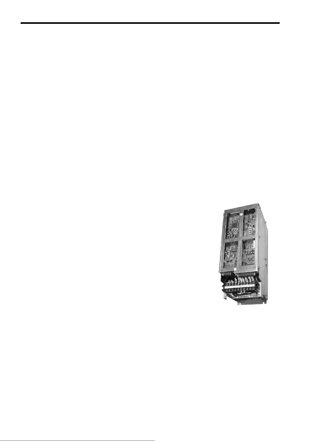
Re-engineered AC SERVOPACK
USER'S MANUAL
CACR-SR□□BF SERVOPACK
YA S K A WA
YASKAWA ELECTRIC ENGINEERING CORPORATION
MANUAL NO. KG22E
Page 2

Copyright © 2004 YASKAWA ELECTRIC ENGINEERING CORPORATION
All rights reserved. No part of this publication may be reproduced, stored in a retrieval system,
or transmitted, in any form, or by any means, mechanical, electronic, photocopying, recording,
or otherwise, without the prior written permission of Yaskawa Electric Engineering. No patent
liability is assumed with respect to the use of the information contained herein. Moreover,
because Yaskawa Electric Engineering is constantly striving to improve its high-quality products, the information contained in this manual is subject to change without notice. Every precaution has been taken in the preparation of this manual. Nevertheless, Yaskawa Electric
Engineering assumes no responsibility for errors or omissions. Neither is any liability assumed
for damages resulting from the use of the information contained in this publication.
Page 3

About this manual
Description of Technical Terms
The terms in this manual are defined as follows:
• Re-engineered AC SERVOPACK:
The SERVOPACKs that have been developed to be used for replacement of the conventional
SERVOPACK models prior to Σ series.
• CACR-SRBF1:
The re-engineered AC SERVOPACK model designation. The code in differs depending on the
SERVOPACK capacity and specifications. Refer to 2.2 SERVOPACK Model Designations.
Quick access to your required information
Read the chapters marked with 9 to get the information required for your purpose.
SERVOPACKs,
Chapter
Chapter 1
Outline
Chapter 2
Specifications and
Dimensional
Drawings
Chapter 3
Wiring
Chapter 4
Settings and Display
Chapter 5
Maintenance,
Inspection, and
Alarm/Warning
Display
Servomotors,
and Peripheral
Devices
9
999
9999
Related Manuals
Refer to the following manuals as required.
Ratings and
Characteristics
Panel
Configuration
and Wiring
Trial Operation
9
Maintenance
and Inspection
9
Manual Name Manual Number Contents
Σ-III Series
SGMS/SGDS
Digital Operator
Operation Manual
Σ-III Series
SGMS/SGDS
User’s Manual
TOBPS80000001
SIEPS80000000
Provides detailed information on the operation of the
JUSP-OP05A Digital Operator.
Describes the following items of Σ-III Series
SERVOPACKs and Servomotors.
• Selection of model and capacity
• Ratings, characteristics, and dimensional drawings
• Cables and peripheral devices
• Panel configuration and wiring
• Trial operation, servo adjustment, and functions
• Inspection, maintenance, and troubleshooting
iii
Page 4
Safety Information
The following conventions are used to indicate precautions in this manual. Failure to heed precautions pro-
vided in this manual can result in serious or possibly even fatal injury or damage to the products or to related
equipment and systems.
WARNING
CAUTION
PROHIBITED
MANDATORY
Indicates precautions that, if not heeded, could possibly result in loss of life or serious
injury.
Indicates precautions that, if not heeded, could result in relatively serious or minor
injury, damage to the product, or faulty operation.
In some situations, the precautions indicated could have series consequences if not
heeded.
Indicates prohibited actions that must not be performed. For example, this symbol
would be used to indicate that fire is prohibited as follows: .
Indicates compulsory actions that must be performed. For example, this symbol would
be used as follows to indicate that grounding is compulsory: .
The warning symbols for ISO and JIS standards are different, as shown below.
ISO JIS
The ISO symbol is used in this manual.
Both of these symbols appear on warning labels on Yaskawa Electric Engineering products. Please abide by
these warning labels regardless of which symbol is used.
iv
Page 5
Notes for Safe Operation
Read this manual thoroughly before checking products on delivery, storage and transportation, installation,
wiring, operation and inspection, and disposal of the AC servo drives.
WARNING
• Never touch any rotating motor parts while the motor is running.
Failure to observe this warning may result in injury.
• Before starting operation with a machine connected, make sure that an emergency stop can
be applied at any time.
Failure to observe this warning may result in injury.
• Never touch the inside of the SERVOPACKs.
Failure to observe this warning may result in electric shock.
• Do not touch terminals for five minutes after the power is turned OFF.
Residual voltage may cause electric shock.
• Do not touch terminals for five minutes after voltage resistance test.
Residual voltage may cause electric shock.
• Follow the procedures and instructions for trial operation precisely as noted in this Manual.
• Follow the procedures and instructions for the trial operation as noted in the applicable man-
ual for that product.
Malfunctions that occur after the servomotor is connected to the equipment not only damage the
equipment, but may also cause an accident resulting in death or injury.
• Do not remove the front cover, cables, connectors, or optional items while the power is ON.
Failure to observe this warning may result in electric shock.
• Installation, disassembly, or repair must be performed only by authorized personnel.
Failure to observe this warning may result in electric shock or injury.
• Do not damage, press, exert excessive force or place heavy objects on the cables.
Failure to observe this warning may result in electric shock, stopping operation of the product, or
burning.
• Provide an appropriate stopping device on the machine side to ensure safety. A holding
brake for a servomotor with brake is not a stopping device for ensuring safety.
Failure to observe this warning may result in injury.
• Do not come close to the machine immediately after resetting momentary power loss to
avoid an unexpected restart. Take appropriate measures to ensure safety against an unex-
pected restart.
Failure to observe this warning may result in injury.
• Do not modify the product.
Failure to observe this warning may result in injury or damage to the product.
• Connect the ground terminal to electrical codes (ground resistance: 100 Ω or less).
Improper grounding may result in electric shock or fire.
v
Page 6
Checking on Delivery
CAUTION
• Always use the servomotor and SERVOPACK in one of the specified combinations.
Failure to observe this caution so may result in fire or malfunction.
Storage and Transportation
CAUTION
• Do not store or install the product in the following places.
• Locations subject to direct sunlight.
• Locations subject to temperatures outside the range specified in the storage/installation temperature conditions.
• Locations subject to humidity outside the range specified in the storage/installation humidity conditions.
• Locations subject to condensation as the result of extreme changes in temperature.
• Locations subject to corrosive or flammable gases.
• Locations subject to dust, salts, or iron dust.
• Locations subject to exposure to water, oil, or chemicals.
• Locations subject to shock or vibration.
Failure to observe this caution may result in fire, electric shock, or damage to the product.
• Do not hold the product by the cables or motor shaft while transporting it.
Failure to observe this caution may result in injury or malfunction.
• Do not place any load exceeding the limit specified on the packing box.
Failure to observe this caution may result in injury or malfunction.
Installation
• Never use the products in an environment subject to water, corrosive gases, inflammable gases, or
combustibles.
Failure to observe this caution may result in electric shock or fire.
• Do not step on or place a heavy object on the product.
Failure to observe this caution may result in injury.
• Do not cover the inlet or outlet ports and prevent any foreign objects from entering the product.
Failure to observe this caution may cause internal elements to deteriorate resulting in malfunction or fire.
• Be sure to install the product in the correct direction.
Failure to observe this caution may result in malfunction.
• Provide the specified clearances between the SERVOPACK and the control panel or with other
devices.
Failure to observe this caution may result in fire or malfunction.
• Do not apply any strong impact.
Failure to observe this caution may result in malfunction.
CAUTION
vi
Page 7

Wiring
CAUTION
• Do not connect a three-phase power supply to the U, V, or W output terminals.
Failure to observe this caution may result in injury or fire.
• Securely connect the power supply terminal screws and motor output terminal screws.
Failure to observe this caution may result in fire.
• Do not bundle or run power and signal lines together in the same duct. Keep power and signal
lines separated by at least 30 cm (11.81 in).
• Use twisted-pair shielded wires or multi-core twisted pair shielded wires for signal and encoder
(PG) feedback lines.
The maximum length is 3 m (118.11 in) for reference input lines and is 20 m (787.40 in) for PG feedback
lines.
• Do not touch the power terminals for 5 minutes after turning power OFF because high voltage may
still remain in the SERVOPACK.
Make sure the charge indicator is out first before starting an inspection.
• Avoid frequently turning power ON and OFF. Do not turn power ON or OFF more than once per
minute.
Since the SERVOPACK has a capacitor in the power supply, a high charging current flows for 0.2 seconds
when power is turned ON. Frequently turning power ON and OFF causes main power devices like capacitors
and fuses to deteriorate, resulting in unexpected problems.
• Be sure to wire correctly and securely.
Failure to observe this caution may result in motor overrun, injury, or malfunction.
• Always use the specified power supply voltage.
An incorrect voltage may result in burning.
• Take appropriate measures to ensure that the input power supply is supplied within the specified
voltage fluctuation range. Be particularly careful in places where the power supply is unstable.
An incorrect power supply may result in damage to the product.
• Install external breakers or other safety devices against short-circuiting in external wiring.
Failure to observe this caution may result in fire.
• Take appropriate and sufficient countermeasures for each when installing systems in the following
locations.
Failure to observe this caution may result in damage to the product.
• Locations subject to static electricity or other forms of noise.
• Locations subject to strong electromagnetic fields and magnetic fields.
• Locations subject to possible exposure to radioactivity.
• Locations close to power supplies.
• Do not reverse the polarity of the battery when connecting it.
Failure to observe this caution may damage the battery or cause it to explode.
vii
Page 8
Operation
CAUTION
• Conduct trial operation on the servomotor alone with the motor shaft disconnected from machine to
avoid any unexpected accidents.
Failure to observe this caution may result in injury.
• Before starting operation with a machine connected, change the settings to match the parameters
of the machine.
Starting operation without matching the proper settings may cause the machine to run out of control or malfunction.
• Forward run prohibited (P-OT) and reverse run prohibited (N-OT) signals are not effective during
JOG mode operation using parameter Fn002 and zero point search mode using parameter Fn003.
• When using the servomotor for a vertical axis, install the safety devices to prevent workpieces to
fall off due to occurrence of alarm or overtravel. Set the servomotor so that it will stop in the zero
clamp state at occurrence of overtravel.
Failure to observe this caution may cause workpieces to fall off due to overtravel.
• When not using the normal autotuning, set to the correct moment of inertia ratio.
Setting to an incorrect moment of inertia ratio may cause vibration.
• Do not touch the SERVOPACK heatsinks, regenerative resistor, or servomotor while power is ON
or soon after the power is turned OFF.
Failure to observe this caution may result in burns due to high temperatures.
• Do not make any extreme adjustments or setting changes of parameters.
Failure to observe this caution may result in injury due to unstable operation.
• When an alarm occurs, remove the cause, reset the alarm after confirming safety, and then resume
operation.
Failure to observe this caution may result in injury.
• Do not use the servo brake of the servomotor for ordinary braking.
Failure to observe this caution may result in malfunction.
viii
Maintenance and Inspection
CAUTION
• When replacing the SERVOPACK, resume operation only after resetting the potentiometers, pins,
and parameters to their original settings.
Failure to observe this caution may result in damage to the product.
• Do not attempt to change wiring while the power is ON.
Failure to observe this caution may result in electric shock or injury.
• Do not disassemble the SERVOPACK.
Failure to observe this caution may result in electric shock or injury.
Page 9

Disposal
CAUTION
• When disposing of the products, treat them as ordinary industrial waste.
General Precautions
The following describes general precautions. Note the following to ensure safe application.
• The drawings presented in this manual are sometimes shown without covers or protective guards. Always
replace the cover or protective guard as specified first, and then operate the products in accordance with
the manual.
• The drawings presented in this manual are typical examples and may not match the product you received.
• This manual is subject to change due to product improvement, specification modification, and manual
improvement. When this manual is revised, the manual code is updated and the new manual is published
as a next edition. The edition number appears on the front and back covers.
• If the manual must be ordered due to loss or damage, inform your nearest Yaskawa Electric Engineering
representative or one of the offices listed on the back of this manual.
• Yaskawa Electric Engineering will not take responsibility for the results of unauthorized modifications of
this product. Yaskawa Electric Engineering shall not be liable for any damages or troubles resulting from
unauthorized modification.
ix
Page 10

CONTENTS
About this manual- - - - - - - - - - - - - - - - - - - - - - - - - - - - - - - - - - - - - - - - - - - - - - - - - - - - - - - iii
SAFETY INFORMATION- - - - - - - - - - - - - - - - - - - - - - - - - - - - - - - - - - - - - - - - - - - - - - - - - - iv
Notes for Safe Operation- - - - - - - - - - - - - - - - - - - - - - - - - - - - - - - - - - - - - - - - - - - - - - - - - - - v
1 Outline
1.1 Outline- - - - - - - - - - - - - - - - - - - - - - - - - - - - - - - - - - - - - - - - - - - - - - - - - - - - - 1-2
1.2 Features - - - - - - - - - - - - - - - - - - - - - - - - - - - - - - - - - - - - - - - - - - - - - - - - - - - 1-2
1.2.1 Compatible with SERVOPACK Operating Environments Prior to Σ-Series - - - - - - - - - - - - - - -1-2
1.2.2 Updated with the Latest Technologies- - - - - - - - - - - - - - - - - - - - - - - - - - - - - - - - - - - - - - - - -1-2
1.2.3 Wide Range of Applicable Servomotors - - - - - - - - - - - - - - - - - - - - - - - - - - - - - - - - - - - - - - -1-2
1.3 Applicable Servomotors and Encoders - - - - - - - - - - - - - - - - - - - - - - - - - - - - - - 1-3
1.4 SERVOPACK Part Names- - - - - - - - - - - - - - - - - - - - - - - - - - - - - - - - - - - - - - - 1-4
2 Specifications and Dimensional Drawings
2.1 Ratings and Specifications - - - - - - - - - - - - - - - - - - - - - - - - - - - - - - - - - - - - - - 2-2
2.2 SERVOPACK Model Designations - - - - - - - - - - - - - - - - - - - - - - - - - - - - - - - - - 2-4
2.3 Re-engineered AC SERVOPACK Selection - - - - - - - - - - - - - - - - - - - - - - - - - - 2-5
2.4 Dimensional Drawings - - - - - - - - - - - - - - - - - - - - - - - - - - - - - - - - - - - - - - - - - 2-7
2.4.1 Re-engineered AC SERVOPACKs for CACR-SR02B to SR44B - - - - - - - - - - - - - - - - - - -2-7
2.4.2 Re-engineered AC SERVOPACK Models for CACR-SR60BB, 60BZ, 60BE, and 60BY - - - - - -2-9
3 Wiring
3.1 Wiring for Re-engineered AC SERVOPACKs CACR-SRBF1 - - - - - - - 3-2
3.1.1 Connection Diagram - - - - - - - - - - - - - - - - - - - - - - - - - - - - - - - - - - - - - - - - - - - - - - - - - - - - -3-2
3.1.2 Names and Description of Main Circuit Terminals - - - - - - - - - - - - - - - - - - - - - - - - - - - - - - - -3-2
3.1.3 Connector Receptacle Specifications - - - - - - - - - - - - - - - - - - - - - - - - - - - - - - - - - - - - - - - - -3-3
3.1.4 CN1 I/O Signal Connector Terminal Layout - - - - - - - - - - - - - - - - - - - - - - - - - - - - - - - - - - - - -3-3
3.1.5 CN2 Optical Encoder (PG) Connector Terminal Layout - - - - - - - - - - - - - - - - - - - - - - - - - - - -3-5
3.2 I/O Signal Connector Terminals - - - - - - - - - - - - - - - - - - - - - - - - - - - - - - - - - - - 3-6
3.2.1 Re-engineered SERVOPACKs for CACR-SRBE
(for Multiplexed Incremental Encoder) - - - - - - - - - - - - - - - - - - - - - - - - - - - - - - - - - - - - - - - -3-6
3.2.2 Re-engineered SERVOPACKs for CACR-SRBB
(for Conventional Incremental Encoder) - - - - - - - - - - - - - - - - - - - - - - - - - - - - - - - - - - - - - - -3-8
3.2.3 Re-engineered SERVOPACKs for CACR-SRBY (for Absolute Encoder) - - - - - - - - - - - -3-10
3.2.4 Re-engineered SERVOPACKs for CACR-SRBZ (for Absolute Encoder)- - - - - - - - - - - - -3-12
x
Page 11

4 Settings and Display
4.1 Setting Switches- - - - - - - - - - - - - - - - - - - - - - - - - - - - - - - - - - - - - - - - - - - - - - 4-2
4.1.1 Setting Fixed Switches (User’s Modification Prohibited) - - - - - - - - - - - - - - - - - - - - - - - - - - - 4-3
4.1.2 Switches To Be Set According to Application - - - - - - - - - - - - - - - - - - - - - - - - - - - - - - - - - - - 4-3
4.1.3 Potentiometers VR and RH - - - - - - - - - - - - - - - - - - - - - - - - - - - - - - - - - - - - - - - - - - - - - - - 4-3
4.1.4 Alarm Reset Button - - - - - - - - - - - - - - - - - - - - - - - - - - - - - - - - - - - - - - - - - - - - - - - - - - - - - 4-4
4.1.5 LED Display - - - - - - - - - - - - - - - - - - - - - - - - - - - - - - - - - - - - - - - - - - - - - - - - - - - - - - - - - - 4-4
4.1.6 Monitoring Pins - - - - - - - - - - - - - - - - - - - - - - - - - - - - - - - - - - - - - - - - - - - - - - - - - - - - - - - - 4-4
4.1.7 Digital Operator Connector- - - - - - - - - - - - - - - - - - - - - - - - - - - - - - - - - - - - - - - - - - - - - - - - 4-4
4.2 Factory Settings - - - - - - - - - - - - - - - - - - - - - - - - - - - - - - - - - - - - - - - - - - - - - - 4-5
4.2.1 Pin Settings - - - - - - - - - - - - - - - - - - - - - - - - - - - - - - - - - - - - - - - - - - - - - - - - - - - - - - - - - - 4-5
4.2.2 List of Parameters - - - - - - - - - - - - - - - - - - - - - - - - - - - - - - - - - - - - - - - - - - - - - - - - - - - - - 4-11
5 Maintenance, Inspection and Alarm/Warning Display
5.1 Status Display - - - - - - - - - - - - - - - - - - - - - - - - - - - - - - - - - - - - - - - - - - - - - - - 5-2
5.2 Alarm Display Table - - - - - - - - - - - - - - - - - - - - - - - - - - - - - - - - - - - - - - - - - - - 5-3
5.3 Warning Displays - - - - - - - - - - - - - - - - - - - - - - - - - - - - - - - - - - - - - - - - - - - - - 5-6
5.4 Inspection and Maintenance - - - - - - - - - - - - - - - - - - - - - - - - - - - - - - - - - - - - - 5-7
5.4.1 Servomotor Inspection - - - - - - - - - - - - - - - - - - - - - - - - - - - - - - - - - - - - - - - - - - - - - - - - - - - 5-7
5.4.2 SERVOPACK Inspection - - - - - - - - - - - - - - - - - - - - - - - - - - - - - - - - - - - - - - - - - - - - - - - - - 5-7
5.4.3 SERVOPACK’s Parts Replacement Schedule - - - - - - - - - - - - - - - - - - - - - - - - - - - - - - - - - - 5-7
xi
Page 12

1
Outline
1.1 Outline - - - - - - - - - - - - - - - - - - - - - - - - - - - - - - - - - - - - - - - - - - - - - - - - - 1-2
1.2 Features - - - - - - - - - - - - - - - - - - - - - - - - - - - - - - - - - - - - - - - - - - - - - - - 1-2
1.2.1 Compatible with SERVOPACK Operating Environments Prior to Σ-Series - - - - - - - - - - 1-2
1.2.2 Updated with the Latest Technologies - - - - - - - - - - - - - - - - - - - - - - - - - - - - - - - - - - - 1-2
1.2.3 Wide Range of Applicable Servomotors - - - - - - - - - - - - - - - - - - - - - - - - - - - - - - - - - - 1-2
1.3 Applicable Servomotors and Encoders - - - - - - - - - - - - - - - - - - - - - - - - - -1-3
1.4 SERVOPACK Part Names - - - - - - - - - - - - - - - - - - - - - - - - - - - - - - - - - - -1-4
1
1-1
Page 13
1 Outline
1.2.1 Compatible with SERVOPACK Operating Environments Prior to Σ-Series
1.1 Outline
The re-engineered AC SERVOPACK model CACR-SRBF has been developed to be used for replacement of
the conventional SERVOPACK models that had been introduced before Σ-series, using the latest technologies in
its circuit configuration.
The re-engineered AC SERVOPACK supports all the types of encoders for AC servodrives: serial encoders and
encoders older than serial encoders
The re-engineered AC SERVOPACK provides the operating environment of the following conventional
SERVOPACK models.
CACR-SRBA
(Speed control/analog control, incremental encoder applicable, base-mounted type)
CACR-SRBB
(Speed control/analog control, incremental encoder applicable, base-mounted type)
CACR-SRBZ
(Speed control/analog control, absolute encoder applicable, base-mounted type)
CACR-SRBE
(Speed control/digital control, incremental encoder applicable, base-mounted type)
CACR-SRBY
(Speed control/digital control, absolute encoder applicable, base-mounted type)
1.2 Features
1.2.1 Compatible with SERVOPACK Operating Environments Prior to Σ-Series
Operating Environments:
• External dimensions/installation
(Some models require attachments.)
• Main circuit terminals
• Control connector and signal layout
• Recognizes the encoder type prior to Σ series by the switch setting
(An encoder signal converter is built in.)
• Important adjustments such as speed gain adjustment can be made
using the potentiometers VR.
(In the same way as of the conventional models CACR-SRBB and BZ)
1.2.2 Updated with the Latest Technologies
• The basic functions and performance are equivalent to those of Σ-III
series SERVOPACK
• The parameters of Σ-III series SERVOPACK are applied.
(Parameter setting using a digital operator.)
1.2.3 Wide Range of Applicable Servomotors
The re-engineered AC SERVOPACKs can be combined with various models of servomotors by setting the internal parameters: C series, M series, F series, G series, D series, S series, Σ-series, Σ-II series, and Σ-III series Servomotors.
1-2
Page 14
1.3 Applicable Servomotors and Encoders
The following servomotors besides Σ series, Σ-II series, Σ-III series are applicable.
Αpplicable Servomotor Models Prior to Σ Series
C Series M Series F Series G Series D Series S Series
USACED-03A
USACED-05A
USACED-12A
USACED-20A
USACED-30A
USACED-44A
USACED-60A
Applicable Encoders
Conventional Incremental Encoders 1000 p/r, 1500 p/r, 2500 p/r, 4000 p/r, 5000 p/r, 6000 p/r
Multiplexed Incremental Encoders 2048 p/r, 8192 p/r
Absolute Encoders 1024 p/r, 8192 p/r
USAMED-03
USAMED-06
USAMED-09
USAMED-12
USAMED-20
USAMED-30
USAMED-44
USAMED-60
USAFED-02
USAFED-03
USAFED-05
USAFED-09
USAFED-13
USAFED-20
USAFED-30
USAFED-44
USAGED-02A
USAGED-03A
USAGED-05A
USAGED-09A
USAGED-13A
USAGED-20A
USAGED-30A
USAGED-44A
1.3 Applicable Servomotors and Encoders
USADED-05E
USADED-10E
USADED-15E
USADED-22E
USADED-37E
USAGED-44A
USASEM-02A
USASEM-03A
USASEM-05A
USASEM-08A
USASEM-15A
USASEM-30A
1
1-3
Page 15
1 Outline
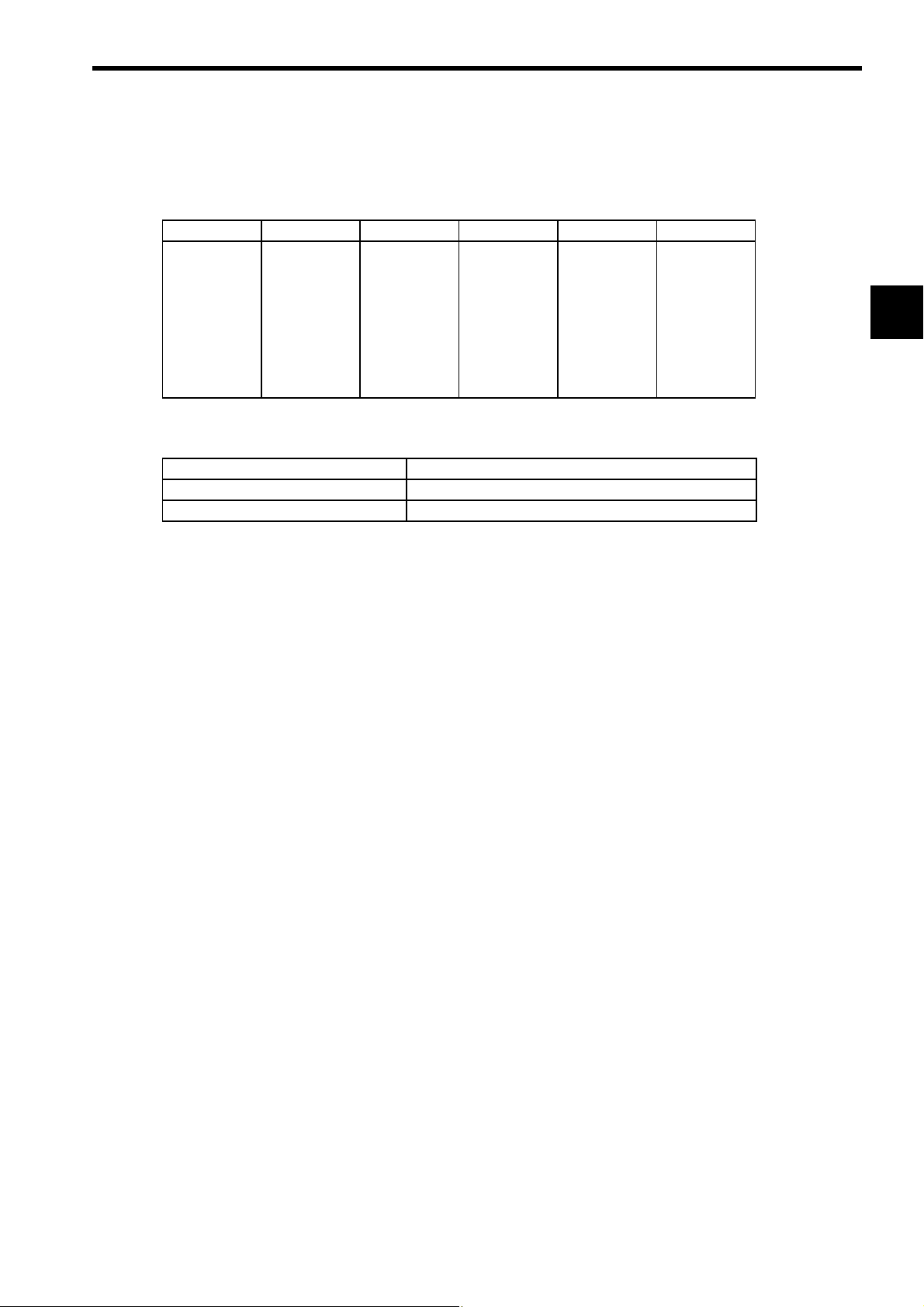
1.4 SERVOPACK Part Names
Control/main circuit
power supply terminal
CN3 Connector for personal
computer monitoring or
digital operator
CN1 I/O signal connector
CN2 Encoder connector
1-4
Page 16

2
Specifications and Dimensional Drawings
2.1 Ratings and Specifications - - - - - - - - - - - - - - - - - - - - - - - - - - - - - - - - - - -2-2
2.2 SERVOPACK Model Designations - - - - - - - - - - - - - - - - - - - - - - - - - - - - - 2-4
2.3 Re-engineered AC SERVOPACK Selection - - - - - - - - - - - - - - - - - - - - - - - 2-5
2.4 Dimensional Drawings - - - - - - - - - - - - - - - - - - - - - - - - - - - - - - - - - - - - - 2-7
2.4.1 Re-engineered AC SERVOPACKs for CACR-SR02B to SR44B - - - - - - - - - - - - - - 2-7
2.4.2 Re-engineered AC SERVOPACK Models for CACR-SR60BB, 60BZ, 60BE, and 60BY 2-9
2
2-1
Page 17
2 Specifications and Dimensional Drawings
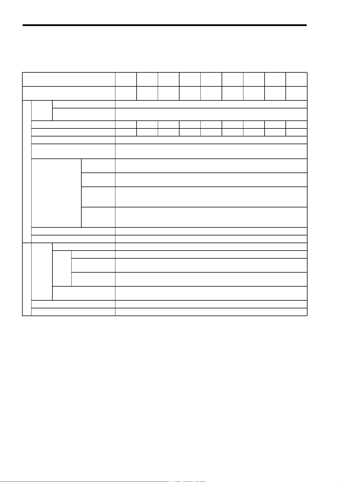
2.1 Ratings and Specifications
Re-engineered SERVOPACK Model
CACR-
Max. Applicable Servomotor Capacity
[kW]
Input
Power
Supply
Continuous Output Current [Arms]
Max. Output Current [Arms]
Control Method Three-phase full-wave rectification IGBT-PWM (sine-wave driven)
Feedback
Operating
Conditions
Configuration Base-mounted
Approx. Mass 10 kg
Basic Specifications
Speed
Control
Torque Control (Repeatability) ±2 %
Acceleration Time Setting 0 to 10 s
Performance
Main Circuit Three-phase 200 to 230 VAC +10 to -15 %, 50/60 Hz
Control Circuit Single-phase 200 to 230 VAC +10 to -15 %, 50/60 Hz
Ambient
Temperature
Storage
Temperature
Ambient/
Storage
Humidity
Vibration/
Shock
Resistance
Speed Control Range 1:3000
Load Regulation 0 to 100 % load: 0.01 % max. (at rated speed)
Speed
Regulation
Frequency
Characteristics
Voltage
Regulation
Temperature
Regulation
SR03BF SR05BF SR07BF SR10BF SR15BF SR20BF SR30BF SR44BF SR60BF
0.3 0.5 0.7 1.0 1.5 2.0 3.0 4.4 6.0
3.0 4.2 5.8 7.6 11.7 19.0 26.0 33.0 45.0
8.5 11.0 13.9 17.0 28.0 42.0 56.6 70.0 80.6
Incremental encoder/Absolute encoder
(8192 p/r, 2048 p/r, 1024 p/r, 6000 p/r, 5000 p/r, 4000 p/r, 2500 p/r, 1500 p/r, 1000 p/r, etc.)
0 to 55 °C
-20 to 85 °C
90 % RH or less (with no condensation)
5 m/s2 / 20 m/s2 (0.5G/2G)
0 %
25±25 °C: 0.1% max. (at rated speed)
100 Hz
2-2
Page 18
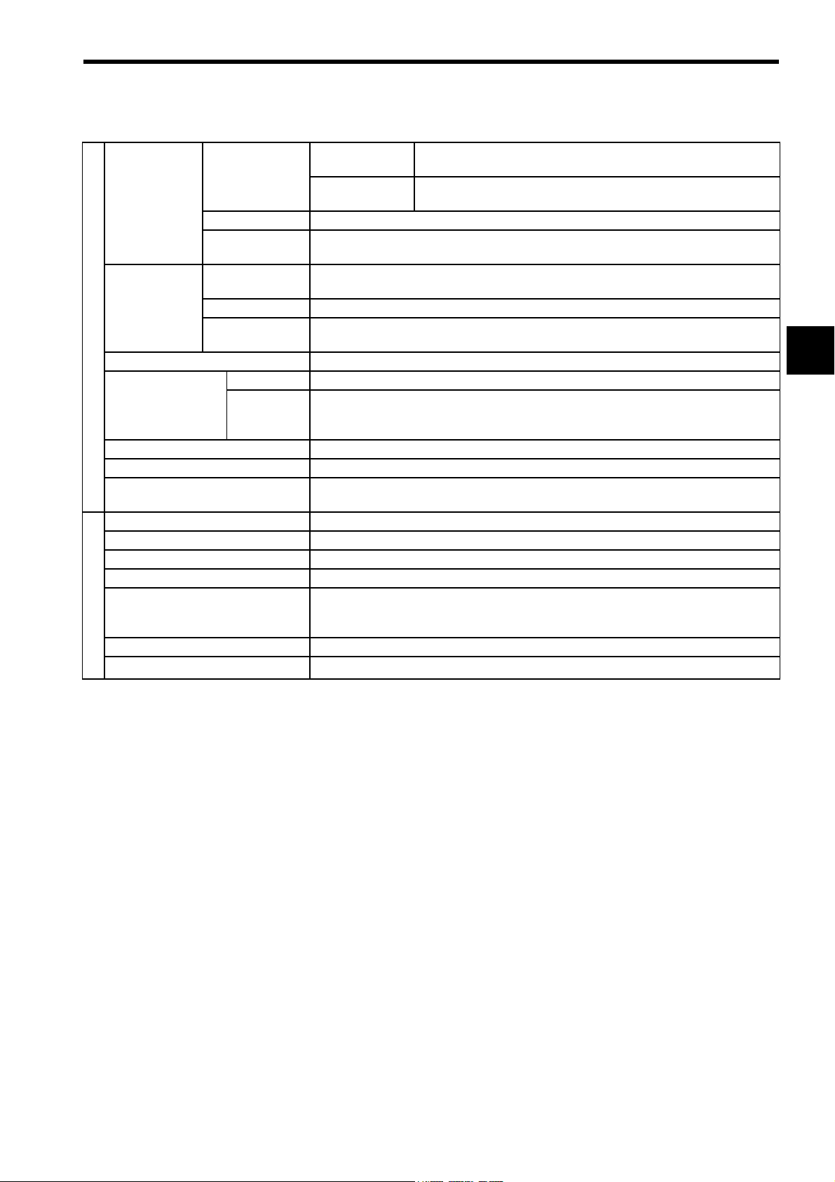
2.1 Ratings and Specifications
Speed control
Rated Refer-
Speed/Torque
References
Auxiliary Inputs
Built-in Reference Power Supply ±12 VDC±5 %, ±30 mA
Position Output
(PG pulses)
Sequence Input Servo ON, P control, forward run prohibited, reverse run prohibited, and alarm reset
Sequence Output Servo alarm, servo ready, TG ON, current limit, and alarm code (3-bit output)
External Current Limits
I/O Signals
Dynamic Brake (DB) Operated at main power OFF, servo alarm, servo OFF.
Regenerative Processing Built-in
Allowable Load Moment of Inertia 5 times of rotor moment of inertia
Overtravel Prevention Operated at P-OT and N-OT
Protection
LED Display 7-segment LED (status and alarm display)
Monitor
Built-in Functions
ence Voltage
Input Impedance About 30 kΩ
Circuit Time
Constant
Rated Reference Voltage
Input Impedance About 30 kΩ
Circuit Time
Constant
Form Line-driver or open-collector (phase A, phase B, phase C)
Frequency
Dividing
Ratio
mode
Torque control
mode
About 70 µs
±2 V to ±10 VDC (forward rotation with positive reference) at rated speed.
About 70 µs
Any setting ratio
±0 V to ±9 VDC, forward rotation: -3 VDC/rated current, reverse rotation: 3 VDC/rated
current
Overcurrent, regeneration error, overvoltage, input overvoltage, overspeed, insufficient
voltage, overload, zero-point pulse error, A/D error, overrun detection, open-phase, and
CPU error
Speed monitor 1000 r/min
±6 VDC (forward rotation with positive reference) at rated speed
±3 VDC (forward rotation with positive reference) at rated torque
-1
and torque monitor 3V/rated torque
(cont’d)
2
2-3
Page 19

2 Specifications and Dimensional Drawings
2.2 SERVOPACK Model Designations
This section explains how to check the SERVOPACK model.
CACR-SRBF1-Y
SERVOPACK prior to the Σ series
SERVOPACK for speed control
Capacity.
Base-mounted re-engineered AC SERVOPACK
Input voltage: 200 V
Applicable encoder
Applicable servomotor
Conventional SERVOPACK model
Y-specification code (Customer-specified code)
(1) SERVOPACK Capacity and Applicable Servomotors (*1, *2)
∗1
∗3
∗2
∗4
*1 Capacity code
(2) Encoders (*3)
Type Pulse Code Type Pulse Code Type Pulse Code
1000 F
1440 H 8192 2 8192 S
1500 E 2500 4
Conventional
incremental
2000 K
2500 C
4000 D
5000 B
6000 A
*2 Applicable servomotor code
MFGSDC
02 − 0.15 0.15 0.15 −−
03 0.3 0.3 0.3 0.31 − 0.25
05 − 0.45 0.45 0.46 0.5 0.5
07 0.6 −−−−−
10 0.9 0.85 0.85 0.77 −−
15 1.2 1.3 1.3 1.54 1.0 1.2
20 2.0 1.8 1.8 − 1.5 1.8
30 3.0 2.9 2.9 3.08 2.2 2.9
44 4.4 4.4 4.4 − 3.7 4.4
60 6.0 −−−−6.0
2048 3
Multiplexed
Absolute
incremental
Unit: kW
1024 W
2-4
(3) Conventional SERVOPACKs (*4)
Model Code
CACR-SRBB B
CACR-SRBZ Z
CACR-SRBE E
CACR-SRBY Y
CACR-SRBA A
Page 20

2.3 Re-engineered AC SERVOPACK Selection
2.3 Re-engineered AC SERVOPACK Selection
Conventional SERVOPACK Model SRBB
Applicable
Servomotors
USAMED-03 CACR-SR03BB1MCACR-SR03BF1MB CACR-SR03BZ1M CACR-SR03BF1MZ
USAMED-06 CACR-SR07BB1MCACR-SR07BF1MB CACR-SR07BZ1M CACR-SR07BF1MZ
USAMED-09 CACR-SR10BB1MCACR-SR10BF1MB CACR-SR10BZ1M CACR-SR10BF1MZ
USAMED-12 CACR-SR15BB1MCACR-SR15BF1MB CACR-SR15BZ1M CACR-SR15BF1MZ
M
USAMED-20 CACR-SR20BB1MCACR-SR20BF1MB CACR-SR20BZ1M CACR-SR20BF1MZ
USAMED-30 CACR-SR30BB1MCACR-SR30BF1MB CACR-SR30BZ1M CACR-SR30BF1MZ
USAMED-44 CACR-SR44BB1MCACR-SR44BF1MB CACR-SR44BZ1M CACR-SR44BF1MZ
USAMED-60 CACR-SR60BB1MCACR-SR60BF1MB CACR-SR60BZ1M CACR-SR60BF1MZ
USAFED-02 CACR-SR03BB1F CACR-SR03BF1FB CACR-SR03BZ1F CACR-SR03BF1FZ
USAFED-03 CACR-SR03BB1F CACR-SR03BF1FB CACR-SR03BZ1F CACR-SR03BF1FZ
USAFED-05 CACR-SR05BB1F CACR-SR05BF1FB CACR-SR05BZ1F CACR-SR05BF1FZ
USAFED-09 CACR-SR10BB1F CACR-SR10BF1FB CACR-SR10BZ1F CACR-SR10BF1FZ
F
USAFED-13 CACR-SR15BB1F CACR-SR15BF1FB CACR-SR15BZ1F CACR-SR15BF1FZ
USAFED-20 CACR-SR20BB1F CACR-SR20BF1FB CACR-SR20BZ1F CACR-SR20BF1FZ
USAFED-30 CACR-SR30BB1F CACR-SR30BF1FB CACR-SR30BZ1F CACR-SR30BF1FZ
USAFED-44 CACR-SR44BB1F CACR-SR44BF1FB CACR-SR44BZ1F CACR-SR44BF1FZ
USAGED-02A
USAGED-03A
USAGED-05A
USAGED-09A
G
USAGED-13A
USAGED-20A
USAGED-30A
USAGED-44A
USADED-05E CACR-SR05BB1D CACR-SR05BF1DB CACR-SR05BZ1D CACR-SR05BF1DZ
USADED-10E CACR-SR10BB1D CACR-SR10BF1DB CACR-SR10BZ1D CACR-SR10BF1DZ
D
USADED-15E CACR-SR20BB1D CACR-SR20BF1DB CACR-SR20BZ1D CACR-SR20BF1DZ
USADED-22E CACR-SR30BB1D CACR-SR30BF1DB CACR-SR30BZ1D CACR-SR30BF1DZ
USADED-37E CACR-SR44BB1D CACR-SR44BF1DB CACR-SR44BZ1D CACR-SR44BF1DZ
USASEM-02A CACR-SR02BB1S CACR-SR02BF1SB CACR-SR02BZ1S CACR-SR02BF1SZ
USASEM-03A CACR-SR03BB1S CACR-SR03BF1SB CACR-SR03BZ1S CACR-SR03BF1SZ
USASEM-05A CACR-SR05BB1S CACR-SR05BF1SB CACR-SR05BZ1S CACR-SR05BF1SZ
S
USASEM-08A CACR-SR10BB1S CACR-SR10BF1SB CACR-SR10BZ1S CACR-SR10BF1SZ
USASEM-15A CACR-SR15BB1S CACR-SR15BF1SB CACR-SR15BZ1S CACR-SR15BF1SZ
USASEM-30A CACR-SR30BB1S CACR-SR30BF1SB CACR-SR30BZ1S CACR-SR30BF1SZ
and Re-engineered SERVOPACK Model
Conventional Model
SRBB
Re-engineered Model
SRBF
Conventional SERVOPACK Model SRBZ
and Re-engineered SERVOPACK Model
Conventional Model
SRBZ
Re-engineered Model
SRBF
2
2-5
Page 21

2 Specifications and Dimensional Drawings
Conventional SERVOPACK Model SRBE
Applicable
Servomotors
USAMED-03 CACR-SR03BE1M CACR-SR03BF1ME CACR-SR03BY1M CACR-SR03BF1MY
USAMED-06 CACR-SR07BE1M CACR-SR07BF1ME CACR-SR07BY1M CACR-SR07BF1MY
USAMED-09 CACR-SR10BE1M CACR-SR10BF1ME CACR-SR10BY1M CACR-SR10BF1MY
USAMED-12 CACR-SR15BE1M CACR-SR15BF1ME CACR-SR15BY1M CACR-SR15BF1MY
M
USAMED-20 CACR-SR20BE1M CACR-SR20BF1ME CACR-SR20BY1M CACR-SR20BF1MY
USAMED-30 CACR-SR30BE1M CACR-SR30BF1ME CACR-SR30BY1M CACR-SR30BF1MY
USAMED-44 CACR-SR44BE1M CACR-SR44BF1ME CACR-SR44BY1M CACR-SR44BF1MY
USAMED-60 CACR-SR60BE1M CACR-SR60BF1ME CACR-SR60BY1M CACR-SR60BF1MY
USAFED-02 CACR-SR03BE1F CACR-SR03BF1FE CACR-SR03BY1F CACR-SR03BF1FY
USAFED-03 CACR-SR03BE1F CACR-SR03BF1FE CACR-SR03BY1F CACR-SR03BF1FY
USAFED-05 CACR-SR05BE1F CACR-SR05BF1FE CACR-SR05BY1F CACR-SR05BF1FY
USAFED-09 CACR-SR10BE1F CACR-SR10BF1FE CACR-SR10BY1F CACR-SR10BF1FY
F
USAFED-13 CACR-SR15BE1F CACR-SR15BF1FE CACR-SR15BY1F CACR-SR15BF1FY
USAFED-20 CACR-SR20BE1F CACR-SR20BF1FE CACR-SR20BY1F CACR-SR20BF1FY
USAFED-30 CACR-SR30BE1F CACR-SR30BF1FE CACR-SR30BY1F CACR-SR30BF1FY
USAFED-44 CACR-SR44BE1F CACR-SR44BF1FE CACR-SR44BY1F CACR-SR44BF1FY
USAGED-02A CACR-SR02BE1GCACR-SR02BF1GE CACR-SR02BY1G CACR-SR02BF1GY
USAGED-03A CACR-SR03BE1GCACR-SR03BF1GE CACR-SR03BY1G CACR-SR03BF1GY
USAGED-05A CACR-SR05BE1GCACR-SR05BF1GE CACR-SR05BY1G CACR-SR05BF1GY
USAGED-09A CACR-SR10BE1GCACR-SR10BF1GE CACR-SR10BY1G CACR-SR10BF1GY
G
USAGED-13A CACR-SR15BE1GCACR-SR15BF1GE CACR-SR15BY1G CACR-SR15BF1GY
USAGED-20A CACR-SR20BE1GCACR-SR20BF1GE CACR-SR20BY1G CACR-SR20BF1GY
USAGED-30A CACR-SR30BE1GCACR-SR30BF1GE CACR-SR30BY1G CACR-SR30BF1GY
USAGED-44A CACR-SR44BE1GCACR-SR44BF1GE CACR-SR44BY1G CACR-SR44BF1GY
USADED-05E CACR-SR05BE1DCACR-SR05BF1DE CACR-SR05BY1D CACR-SR05BF1DY
USADED-10E CACR-SR10BE1DCACR-SR10BF1DE CACR-SR10BY1D CACR-SR10BF1DY
D
USADED-15E CACR-SR20BE1DCACR-SR20BF1DE CACR-SR20BY1D CACR-SR20BF1DY
USADED-22E CACR-SR30BE1DCACR-SR30BF1DE CACR-SR30BY1D CACR-SR30BF1DY
USADED-37E CACR-SR44BE1DCACR-SR44BF1DE CACR-SR44BY1D CACR-SR44BF1DY
USASEM-02A CACR-SR02BE1S CACR-SR02BF1SE CACR-SR02BY1S CACR-SR02BF1SY
USASEM-03A CACR-SR03BE1S CACR-SR03BF1SE CACR-SR03BY1S CACR-SR03BF1SY
USASEM-05A CACR-SR05BE1S CACR-SR05BF1SE CACR-SR05BY1S CACR-SR05BF1SY
S
USASEM-08A CACR-SR10BE1S CACR-SR10BF1SE CACR-SR10BY1S CACR-SR10BF1SY
USASEM-15A CACR-SR15BE1S CACR-SR15BF1SE CACR-SR15BY1S CACR-SR15BF1SY
USASEM-30A CACR-SR30BE1S CACR-SR30BF1SE CACR-SR30BY1S CACR-SR30BF1SY
and Re-engineered SERVOPACK Model
Conventional Model
Re-engineered Model
SR
BF
Conventional SERVOPACK Model
SRBYand Re-enginerred SERVOPACK
Model
Conventional Model
Re-engineered Model
SR
BF
2-6
Page 22

2.4 Dimensional Drawings
2.4 Dimensional Drawings
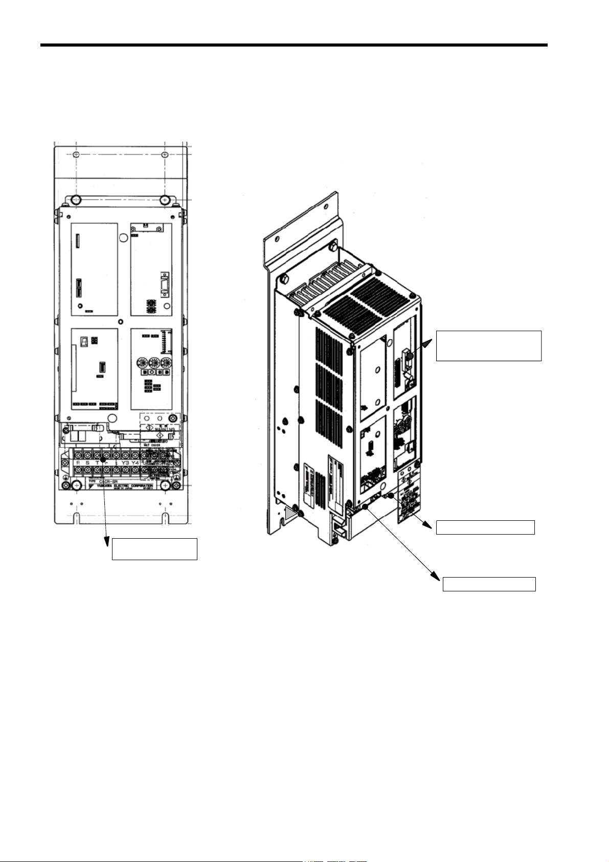
2.4.1 Re-engineered AC SERVOPACKs for CACR-SR02B to SR44B
(1) Re-engineered AC SERVOPACK Models for Conventional Models CACR-SRBB
and -SRBZ
Note: at the end of the model codes of the re-engineered AC SERVOPACK for CACR-SRBB is “B” , and
that for CACR-SRBZ is “Z” .
For Conventional M-series For Conventional F-series For Conventional D-series For Conventional S-series
Models for which no mounting attachment is required
CACR-SR03BF1M CACR-SR03BF1F CACR-SR05BF1D CACR-SR02BF1S
CACR-SR07BF1M CACR-SR05BF1F CACR-SR10BF1D CACR-SR03BF1S
CACR-SR10BF1M CACR-SR10BF1F CACR-SR05BF1S
CACR-SR15BF1M CACR-SR15BF1F CACR-SR10BF1S
CACR-SR15BF1S
CACR-SR30BF1S
Models for which the mounting attachment F352086-A is required
CACR-SR20BF1M CACR-SR20BF1F CACR-SR20BF1D CACR-SR30BF1S
CACR-SR30BF1M CACR-SR30BF1F CACR-SR30BF1D
CACR-SR44BF1M CACR-SR44BF1F CACR-SR44BF1D
2
2-7
Page 23

2 Specifications and Dimensional Drawings
2.4.1 Re-engineered AC SERVOPACKs for CACR-SR02B to SR44B
(2) Re-engineered AC SERVOPACK Models for Conventional Models CACR-SRBE
and -SRBY
Note: at the end of the model codes of the re-engineered AC SERVOPACK for CACR-SRBE is “E” , and
that for CACR-SRBY is “Y” .
For Conventional
M-series
For Conventional
F-series
For Convention
D-series
For Conventional
S-series
For Conventional
G-series
No mounting attachment is required for SERVOPACKs 4.4 kW or less.
CACR-SR03BF1M CACR-SR03BF1F CACR-SR05BF1D CACR-SR02BF1S CACR-SR02BF1G
CACR-SR07BF1M CACR-SR05BF1F CACR-SR10BF1D CACR-SR03BF1S CACR-SR03BF1G
CACR-SR10BF1M CACR-SR10BF1F CACR-SR20BF1D CACR-SR05BF1S CACR-SR05BF1G
CACR-SR15BF1M CACR-SR15BF1F CACR-SR30BF1D CACR-SR10BF1S CACR-SR10BF1G
CACR-SR20BF1M CACR-SR20BF1F CACR-SR44BF1D CACR-SR15BF1S CACR-SR15BF1G
CACR-SR30BF1M CACR-SR30BF1F CACR-SR30BF1S CACR-SR20BF1G
CACR-SR44BF1M CACR-SR44BF1F CACR-SR30BF1G
CACR-SR44BF1M CACR-SR44BF1F CACR-SR44BF1G
Attachment
product code:
F352086-A
2 × 7 dia. holes
Dimensions in mm
F352086-A includes:
y Attachment
y SERVOPACK mounting bolts
Mounting base
(included)
Attachment
product code:
F352086-A
4 × SERVOPACK mounting
screws M6 × 16 (included)
2-8
Page 24

2.4 Dimensional Drawings
2.4.2 Re-engineered AC SERVOPACK Models for CACR-SR60BB, 60BZ, 60BE, and 60BY
(1) Re-engineered AC SERVOPACK Models for CACR-SR60BB, 60BZ, 60BE, and 60BY
CACR-SR60BF1MB
CACR-SR60BF1MZ
CACR-SR60BF1ME
CACR-SR60BF1MY
Attachment
product code:
F352087-A
2
2 × 7 dia. holes
F352087-A includes:
y Attachment
y SERVOPACK mounting bolts
Mounting base (included)
Dimensions in mm
4 × SERVOPACK mounting
screws M6 × 16 (included)
Attachment
product code:
F352087-A
2-9
Page 25

3
Wiring
3.1 Wiring for Re-engineered AC SERVOPACKs CACR-SRBF1 - - - 3-2
3.1.1 Connection Diagram - - - - - - - - - - - - - - - - - - - - - - - - - - - - - - - - - - - - - - - - - - - - - - - 3-2
3.1.2 Names and Description of Main Circuit Terminals - - - - - - - - - - - - - - - - - - - - - - - - - - - 3-2
3.1.3 Connector Receptacle Specifications - - - - - - - - - - - - - - - - - - - - - - - - - - - - - - - - - - - 3-3
3.1.4 CN1 I/O Signal Connector Terminal Layout - - - - - - - - - - - - - - - - - - - - - - - - - - - - - - - 3-3
3.1.5 CN2 Optical Encoder (PG) Connector Terminal Layout - - - - - - - - - - - - - - - - - - - - - - - 3-5
3.2 I/O Signal Connector Terminals - - - - - - - - - - - - - - - - - - - - - - - - - - - - - - - 3-6
3.2.1 Re-engineered SERVOPACKs for CACR-SRBE
(for Multiplexed Incremental Encoder) - - - - - - - - - - - - - - - - - - - - - - - - - - - - - - - - - - 3-6
3.2.2 Re-engineered SERVOPACKs for CACR-SRBB
(for Conventional Incremental Encoder) - - - - - - - - - - - - - - - - - - - - - - - - - - - - - - - - - 3-8
3.2.3 Re-engineered SERVOPACKs for CACR-SRBY (for Absolute Encoder) - - - - - - - 3-10
3.2.4 Re-engineered SERVOPACKs for CACR-SRBZ (for Absolute Encoder) - - - - - - - 3-12
3
3-1
Page 26

3 Wiring
3.1.1 Connection Diagram
3.1 Wiring for Re-engineered AC SERVOPACKs
CACR-SRBF1
3.1.1 Connection Diagram
Re-engineered AC SERVOPACK
Regenerative
resistor
Main circuit power supply
Three-phase 200V/220V
50/60 Hz
Control circuit power supply
Single-phase 200V/220V
50/60Hz
Y3 Y4
R
S
T
r
t
Encoder signal
conversion function
built-in
U
V
W
AC Servomotor
A
B
C
M
D
I/O signals
y Speed reference
y PG signal
y Operation signal
Digital operator
JUSP-OP05A
CN1
CN3
CN2
3.1.2 Names and Description of Main Circuit Terminals
Terminal Symbol Name Description
(R) (S) (T)
(U) (V) (W)
(r) (t)
(Y3) (Y4)
Main circuit input
terminals
Servomotor
connection terminals
Control circuit input
terminals
Three-phase 200 to 230 VAC
Connect (U) to the terminal A, (V) to the terminal B, (W) to the terminal C of
Servomotor.
Single-phase 200 to 230 VAC
Ground terminal Connect to the power supply ground terminal and the Servomotor D terminal.
Regenerative resistor
terminals
Regenerative resistor connection terminals (normally not to be connected
externally.)
PG
Encoder
+10 to -15 %, 50/60 Hz
+10 to -15 %, 50/60 Hz
3-2
Page 27

3.1 Wiring for Re-engineered AC SERVOPACKs CACR-SRBF1
3.1.3 Connector Receptacle Specifications
CN1: For I/O signals
Applicable Receptacle Model
Inside
SERVOPACK
MR-50RMA MR-50F MRP-50F01 MR-50L
Soldered Type Caulking Type Case Manufacturer
CN2: For connecting the optical encoder (PG)
Applicable Receptacle Model
Inside
SERVOPACK
MR-20RMA MR-20F MRP-20F01 MR-20L
Soldered Type Caulking Type Case Manufacturer
CN3: For connecting the digital operator
Half-pitch Connector
Plug Shell Manufacturer
10114-3000VE 10314-52A0-008
SUMITOMO 3M
Limited
3.1.4 CN1 I/O Signal Connector Terminal Layout
Re-engineered AC
SERVOPACK
Pin No.
1
2
3
4
5
6
7
8
9
10
11
12
13
14
15
16
17
18
19
20
21
22
23
Model
Model No. ended
with B (Model for
SRBB)
SG SG SG SG
SG SG SG SG
SG SG SG SG
PHA SEN PHA SEN
/V-CMP+ /V-CMP+ /V-CMP+ /V-CMP+
/V-CMP- /V-CMP- /V-CMP- /V-CMP-
+24V-IN +24V-IN +24V-IN +24V-IN
/S-ON /S-ON /S-ON /S-ON
TMON TMON TMON TMON
VTG VTG VTG VTG
SG SG SG SG
IN-A IN-A V-REF V-REF
SG SG SG SG
IN-B IN-B T-REF T-REF
SG SG SG SG
+12V +12V +12V +12V
SG SG SG SG
FG FG FG FG
PCO PCO PCO PCO
/PCO /PCO /PCO /PCO
PHC BAT+ PHC BAT+
/TGON+ /TGON+ /TGON+ /TGON+
/TGON- /TGON- /TGON- /TGON-
CACR-SRBF1
Model No. ended
with Z (Model for
SRBZ)
Model No. ended
with E (Model for
SRBE)
Honda
Communication
Industries Co., Ltd.
Honda
Communication
Industries
Model No. ended
with Y (Model for
Co., Ltd.
SRBY)
3
3-3
Page 28

3 Wiring
3.1.4 CN1 I/O Signal Connector Terminal Layout
Re-engineered AC
SERVOPACK
Model
Pin No.
24
25
26
27
28
29
30
31
32
33
34
35
36
37
38
39
40
41
42
43
44
45
46
47
48
49
50
Model No. ended
with B (Model for
SRBB)
/P-CON /P-CON /P-CON /P-CON
OL- OL- AL01
N-OT N-OT N-OT N-OT
/S-RDY- /S-RDY- /S-RDY- /S-RDY-
/S-RDY+ /S-RDY+ /S-RDY+ /S-RDY+
N-CL N-CL N-CL N-CL
SG SG SG SG
-12V -12V -12V -12V
SG SG SG SG
PA O PAO PA O PAO
/PAO /PAO /PAO /PAO
PBO PBO PBO PBO
/PBO /PBO /PBO /PBO
PHB BAT- PHB BAT-
ALM+ ALM+ ALM+ ALM+
ALM- ALM- ALM- ALM-
OL+ OL+ AL02
P-OT P-OT P-OT P-OT
empty
empty
P-CL P-CL P-CL P-CL
SG SG SG SG
-12V -12V -12V -12V
SG SG SG SG
+12V +12V +12V +12V
SG SG SG SG
FG FG FG FG
* 1. The MCB trip signal output function is not provided for SRBB and SRBZ.
* 2. The PG signal output phase S is not provided for SRBY.
(cont’d)
CACR-SRBF1
Model No. ended
with Z (Model for
SRBZ)
*1
*1
empty
empty
*1
*1
Model No. ended
with E (Model for
SRBE)
Model No. ended
with Y (Model for
SRBY)
*2
empty
*2
empty
AL03 empty
/ALM-RST /ALM-RST
3-4
Page 29

3.1 Wiring for Re-engineered AC SERVOPACKs CACR-SRBF1
3.1.5 CN2 Optical Encoder (PG) Connector Terminal Layout
For Conventional
Pin No.
1 0 V 0 V 0 V
2 0 V 0 V 0 V
3 0 V 0 V 0 V
4 PG5 V PG5 V PG5 V
5 PG5 V PG5 V PG5 V
6 PG5 V PG5 V PG5 V
7 DIR DIR DIR
8 PU −
9 /PU −
10 PV Absolute RST Absolute RST
11 /PV −−
12 PW BAT BAT
13 / PW B AT 0 B AT 0
14 PC PC PC
15 /PC /PC /PC
16 PA PA PA
17 /PA /PA /PA
18 PB PB PB
19 /PB /PB /PB
20 FG FG FG
Incremental
Encoder
For Multiplexed
Type Incremental
Encoder
For Absolute
Encoder
*
−
*
−
3
* The phase S rotation amount serial data of 12-bit absolute PG is not processed.
3-5
Page 30

3 Wiring
3.2.1 Re-engineered SERVOPACKs for CACR-SRBE (for Multiplexed Incremental Encoder)
3.2 I/O Signal Connector Terminals
3.2.1 Re-engineered SERVOPACKs for CACR-SRBE
(for Multiplexed Incremental Encoder)
Example: CACR-SR20BF12FE that have replaced CACR-SR20BE12F
Torque monitor
F-series: 3.0 V±10 %/100 %
Speed monitor
F-series: 2.0 V±10 %/1000 min
Speed reference input
±6V/rated speed
Auxiliary speed reference input
±2 to ±10 V/rated speed
Reverse rotation current limit
-100 %±10 %/+3.0V input
Forward rotation current limit
+100 %±10 %/-3.0V input
Servo ON
24V
when 1RY is ON
P control when 2Ry is ON
(PI control when 2Ry is OFF)
Reverse run prohibited
when N-LS is open
Forward run prohibited
when P-LS is open
Alarm reset
when 9Ry is ON
3Ry turns ON when
current limit detected
4Ry turns ON when
TG turns ON.
5Ry turns OFF for a
servo alarm
6Ry turns ON when
servo ready
Phase A
Phase B
Phase C
PG signal
open collector output
Alarm code output
24V
0 V
0 V
0 V
1Ry
-1
2Ry
N-LS
P-LS
9Ry
3Ry
4Ry
5Ry
6Ry
PAO
/PAO
PBO
/PBO
PCO
/PCO
PHA
PHB
PHC
ALO1
ALO2
ALO3
+24Vin
S-ON
P-CON
N-OT
P-OT
ALM-RST
CLT+
CLT-
TGON+
TGON-
ALM+
ALM-
S-RDY+
S-RDY-
SERVOPACK
CN1
1-9
1-10
1-12
1-13
1-14
1-15
1-29
1-30
1-44
1-45
1-7
1-8
1-24
1-26
1-41
1-43
1-5
1-6
1-22
1-23
1-38
1-39
1-28
1-27
1-33
P
1-34
1-35
P
1-36
1-19
P
1-20
1-4
1-37
1-21
1-25
1-40
1-42
1-3
1-2
1-1
1-50
1-18
LPF
LPF
LPF
LPF
SG
5 mA
5 mA
5 mA
5 mA
5 mA
SG
CACR-SR20BF12FE
16-bit
D/A
16-bit
D/A
16-bit
D/A
Output
Max. voltage
Max. current
Output line driver
LS75ALS174
+12 V
SG
Output open
collector
LS07
-12 V
CPU
30 VDC
30 mA
1-16
1-48
1-17
1-32
1-47
1-49
1-11
1-31
1-46
3-6
Page 31

3.2 I/O Signal Connector Terminals
Optical encoder
PG
SERVOPACK
CACR-SR20BF12FE
CN2
A
B
C
D
E
F
K
Z
L
/Z
P
P
P
2-16
2-17
2-18
2-19
2-14
2-15
PA
/PA
PB
/PB
PC
/PC
3
H
G
2-4
2-1
2-5
PG5 V
PG0 V
2-2
2-6
2-3
2-7
J
2-20
DIR
1-50
3-7
Page 32

3 Wiring
3.2.2 Re-engineered SERVOPACKs for CACR-SRBB (for Conventional Incremental Encoder)
3.2.2 Re-engineered SERVOPACKs for CACR-SRBB
(for Conventional Incremental Encoder)
Example: CACR-SR20BF1AMB that have replaced CACR-SR20BB1AM
Torque monitor
M-series: 3.0 V±10 %/100 %
Speed monitor
M-series: 4.0 V±10 %/1000 min
Speed reference input
±6 V/rated speed
Auxiliary speed reference input
±2 to ±10 V/rated speed
Reverse rotation current limit
-100 %±10 %/+3.0 V input
Forward rotation current limit
+100 %±10 %/-3.0 V input
Servo ON
when 1Ry is ON
24V
P control when 2Ry is ON
(PI control when 2Ry is OFF)
Reverse run prohibited
when N-LS is open
Forward run prohibited
when P-LS is open
3Ry turns ON when
current limit detected
24V
4Ry turns ON
when TG turns ON
5Ry turns OFF for a
servo alarm
6Ry turns ON when
servo ready
1Ry
2Ry
N-LS
P-LS
3Ry
4Ry
5Ry
6Ry
-1
+24Vin
S-ON
P-CON
N-OT
P-OT
CLT+
CLT-
TGON+
TGON-
ALM+
ALM-
S-RDY+
S-RDY-
SERVOPACK
CN1
1-9
1-10
1-12
1-13
1-14
1-15
1-29
1-30
1-44
1-45
1-7
1-8
1-24
1-26
1-41
1-5
1-6
1-22
1-23
1-38
1-39
1-28
1-27
5 mA
5 mA
5 mA
5 mA
SG
CACR-SR20BF1AMB
limit
Current
Output
Max. voltage: 30 VDC
Max. current: 30 mA
3-8
8Ry
PAO
/PAO
PBO
/PBO
PCO
/PCO
PHA
PHB
PHC
OL
OL-
1-40
1-25
1-33
P
1-34
1-35
P
1-36
1-19
P
1-20
1-4
1-37
1-21
1-3
1-2
1-1
1-50
1-18
8Ry turns OFF for a
OL alarm
Phase A
Phase B
Phase C
PG signal
open collector output
0 V
0 V
0 V
Note: MCB trip (CN1-43 and -42) outputs are not provided.
SG
Output line driver
LS75ALS174
+12 V
SG
Output open
collector
LS07
-12 V
1-16
1-48
1-17
1-32
1-47
1-49
1-11
1-31
1-46
Page 33

3.2 I/O Signal Connector Terminals
PG
SERVOPACKOptical Encoder
A
B
C
D
E
F
K
L
M
N
P
R
H
G
P
P
P
P
P
P
CN2
2-16
2-17
2-18
2-19
2-14
2-15
2-8
2-9
2-10
2-11
2-12
2-13
2-4
2-1
PA
/PA
PB
/PB
PC
/PC
PU
/PU
PV
/PV
PW
/PW
CACR-SR20BF1AMB
3
PG5V
PG0V
2-5
2-2
2-6
2-3
2-7
J
2-20
DIR
1-50
3-9
Page 34

3 Wiring
3.2.3 Re-engineered SERVOPACKs for CACR-SRBY (for Absolute Encoder)
3.2.3 Re-engineered SERVOPACKs for CACR-SRBY (for Absolute Encoder)
Example: CACR-SR20BF1SFY that have replaced CACR-SR20BY1SF
SERVOPACK CACR-SR20BF1SFY
Torque monitor
F-series: 3.0 V±10 %/100 %
Speed monitor
F-series: 2.0 V±10 %/1000 min
Speed reference input
±6 V/rated speed
Auxiliary speed reference input
±2 to ±10 V/rated speed
Reverse rotation current limit
-100 %±10 %/+3.0 V input
Forward rotation current limit
+100 %±10 %/-3.0 V input
Servo ON
24 V
when 1Ry is ON
P control when 2Ry is ON
(PI control when 2Ry is OFF)
Reverse run prohibited
when N-LS is open
Forward run prohibited
when P-LS is open
Alarm reset
when 9Ry is ON
3Ry turns ON when
current limit detected
4Ry turns ON when
TG turns ON
5Ry turns OFF for a
servo alarm
6Ry turns ON when
servo ready
Phase A
Phase B
Phase C
Battery
2.8 to 4.5 V
24 V
SEN
0SEN
0V
0V
-1
+24Vin
1Ry
+
2Ry
N-LS
P-LS
9Ry
3Ry
4Ry
5Ry
6Ry
/PAO
PBO
/PBO
PCO
/PCO
BAT
BAT0
S-ON
P-CON
N-OT
P-OT
ALM-RST
CLT+
CLT-
TGON+
TGON-
ALM+
ALM-
S-RDY+
S-RDY-
PAO
CN1
1-9
1-10
1-12
1-13
1-14
1-15
1-29
1-30
1-44
1-45
1-7
1-8
1-24
1-26
1-41
1-43
1-5
1-6
1-22
1-23
1-38
1-39
1-28
1-27
1-33
P
1-34
1-35
P
1-36
1-19
P
1-20
1-2
LPF
LPF
LPF
LPF
SG
5 mA
5 mA
5 mA
5 mA
5 mA
1-4
1-3
1-1
1-21
1-37
16-bit
D/A
16-bit
D/A
16-bit
D/A
Output
Max. voltage: 30 VDC
Max. current: 30 mA
Output line driver
LS75ALS174
+12 V
SG
-12 V
CPU
1-16
1-48
1-17
1-32
1-47
1-49
1-11
1-31
1-46
3-10
1-50
1-18
FG
Page 35

3.2 I/O Signal Connector Terminals
Optical encoder
15-bit absolute encoder
A
B
C
D
E
F
PG
H
G
R
T
S
J
SERVOPACK CACR-SR20BF1SFY
CN2
PA
P
P
P
P
2-16
2-17
2-18
2-19
2-14
2-15
2-4
2-1
2-5
2-2
2-6
2-3
2-10
2-12
2-13
2-20
/PA
PB
/PB
PC
/PC
PG5 V
PG0 V
1-21
1-37
1-50
3
BAT
BAT0
Optical encoder
12-bit absolute encoder
A
B
C
D
E
F
K
PG
L
H
G
R
T
S
J
PS
/PS
Note
SERVOPACK CACR-SR20BF1WFY
CN2
PA
P
P
P
P
2-16
2-17
2-18
2-19
2-14
2-15
2-4
2-1
2-5
2-2
2-6
2-3
2-10
2-12
2-13
2-20
/PA
PB
/PB
PC
/PC
PG5 V
PG0 V
1-21
1-37
1-50
BAT
BAT0
Note: Cut the rotation amount data signal line on the Servomotor encoder cable side.
3-11
Page 36

3 Wiring
3.2.4 Re-engineered SERVOPACKs for CACR-SRBZ (for Absolute Encoder)
3.2.4 Re-engineered SERVOPACKs for CACR-SRBZ (for Absolute Encoder)
Example: CACR-SR20BF1SMZ that have replaced CACR-SR20BZ1SM
Torque monitor
M-series: 3.0 V±10 %/100 %
Speed monitor
M-series: 4.0 V±10 %/1000 min
-1
SERVOPACK CACR-SR20BF1SMZ
CN1
1-9
1-10
Speed reference input
±6 V/rated speed
Auxiliary speed reference input
±2 to ±10 V/rated speed
Reverse rotation current limit
-100 %±10 %/+3.0 V input
Forward rotation current limit
+100 %±10 %/-3.0 V input
Servo ON
24 V
when 1Ry is ON
P control when 2Ry is ON
(PI control when 2Ry is OFF)
Reverse run prohibited
when N-LS is open
Forward run prohibited
when P-LS is open
3Ry turns ON when
current limit detected
24 V
4Ry turns on when
TG turns ON
5Ry turns OFF for a
servo alarm
6Ry turns ON when
servo ready
1Ry
2Ry
N-LS
P-LS
3Ry
4Ry
5Ry
6Ry
+24Vin
S-ON
P-CON
N-OT
P-OT
CLT+
CLT-
TGON+
TGON-
ALM+
ALM-
S-RDY+
S-RDY-
1-12
1-13
1-14
1-15
1-29
1-30
1-44
1-45
1-7
1-8
1-24
1-26
1-41
1-5
1-6
1-22
1-23
1-38
1-39
1-28
1-27
SG
5 mA
5 mA
5 mA
5mA
limit
Current
Output
Max. voltage: 30 VDC
Max. current: 30 mA
8Ry
PAO
/PAO
PBO
/PBO
PCO
/PCO
BAT
BAT0
OL
OL-
1-40
1-25
1-33
P
1-34
1-35
P
1-36
1-19
P
1-20
1-4
1-3
1-2
1-1
1-21
1-37
1-50
1-18
8Ry turns OFF for a
OL alafm
Battery
2.8 to 4.5 V
Phase A
Phase B
Phase C
SEN
0SEN
0 V
0 V
+
Note: MCB trip (CN1-43 and -42) outputs are not provided.
SG
Output line driver
LS75ALS174
+12 V
SG
-12 V
1-16
1-48
1-17
1-32
1-47
1-49
1-11
1-31
1-46
3-12
Page 37

3.2 I/O Signal Connector Terminals
Optical encoder
15-bit absolute encoder
PG
SERVOPACK
CACR-SR20BF1SMZ
CN2
A
B
C
D
E
F
H
G
P
P
P
2-16
2-17
2-18
2-19
2-14
2-15
2-4
2-1
2-5
2-2
2-6
/PA
PB
/PB
PC
/PC
PA
PG5 V
PG0 V
3
2-3
R
T
S
J
P
2-10
2-12
2-13
2-20
1-21
1-37
1-50
BAT
BAT0
3-13
Page 38

4
Settings and Display
4.1 Setting Switches - - - - - - - - - - - - - - - - - - - - - - - - - - - - - - - - - - - - - - - - - - 4-2
4.1.1 Setting Fixed Switches (User’s Modification Prohibited) - - - - - - - - - - - - - - - - - - - - - - 4-3
4.1.2 Switches To Be Set According to Application - - - - - - - - - - - - - - - - - - - - - - - - - - - - - - 4-3
4.1.3 Potentiometers VR and RH - - - - - - - - - - - - - - - - - - - - - - - - - - - - - - - - - - - - - - - - - - 4-3
4.1.4 Alarm Reset Button - - - - - - - - - - - - - - - - - - - - - - - - - - - - - - - - - - - - - - - - - - - - - - - - 4-4
4.1.5 LED Display - - - - - - - - - - - - - - - - - - - - - - - - - - - - - - - - - - - - - - - - - - - - - - - - - - - - - 4-4
4.1.6 Monitoring Pins - - - - - - - - - - - - - - - - - - - - - - - - - - - - - - - - - - - - - - - - - - - - - - - - - - - 4-4
4.1.7 Digital Operator Connector - - - - - - - - - - - - - - - - - - - - - - - - - - - - - - - - - - - - - - - - - - - 4-4
4.2 Factory Settings - - - - - - - - - - - - - - - - - - - - - - - - - - - - - - - - - - - - - - - - - -4-5
4.2.1 Pin Settings - - - - - - - - - - - - - - - - - - - - - - - - - - - - - - - - - - - - - - - - - - - - - - - - - - - - - 4-5
4.2.2 List of Parameters - - - - - - - - - - - - - - - - - - - - - - - - - - - - - - - - - - - - - - - - - - - - - - - - 4-11
4
4-1
Page 39

4 Settings and Display
4.1 Setting Switches
The setting switches are provided on the board inside the re-engineered AC SERVOPACK CACR-SRBF to
ensure the operating environment of the corresponding conventional model.
There are two types of switches: The switches that have been set and fixed according to the corresponding con-
ventional model before shipment, and the switches that need to be set by users according to the application.
CN503
CN17
31
SL5
LED lamp
(1
(CHARGE)
DS1
CN12
CN22 CN23
S2
SW2
CN24
31
3
3
CN13
CN14
1
1
SW3
31
SL7
CN21 CN11 CN10
331131
CN2
3131
3131
CN4 CN16
TMON
VTG
GND
LED lamp (2
RUN ALARM
31
CN20
LED lamp (3
CN15
1
DSW1 DSW5
CN26
331
ZERO LOOP IN-B
PG5V RESET VR5 FINE
CN18
CN7
CN5
31
31
31
31
CUR
CN6
CN1
CN3
CN19
CN8
CN9
4-2
Page 40

4.1.1 Setting Fixed Switches (User’s Modification Prohibited)
The switches listed in the table below have been set to the appropriate values before shipment.
Do not change the settings of these switches. Doing so will cause motor runaway or SERVOPACK failure.
Switch No. Name Remarks
CN4 Model depended function selection switch
CN5 Model depended function selection switch
CN6 Model depended function selection switch
CN7 Model depended function selection switch
CN8 Model depended function selection switch Not mounted
CN9 Model depended function selection switch Not mounted
CN10 Model depended function selection switch
CN11 Model depended function selection switch
CN13 Model depended function selection switch
CN14 Model depended function selection switch
CN15 Model depended function selection switch
CN16 Model depended function selection switch
CN18 Model depended function selection switch
CN20 Model depended function selection switch
CN21 Model depended function selection switch
CN22 Model depended function selection switch
CN23 Model depended function selection switch
CN24 Model depended function selection switch
CN26 Model depended function selection switch
S2 Model depended function selection switch
SL5 Speed feedback gain switching
SW3-7 Speed feedback gain switching
CN503 PC connection connector Connector for personal computer cable
4.1 Setting Switches
4
4.1.2 Switches To Be Set According to Application
The switches listed in the table below need to be set by users according to the application.
Switch No. Name Remarks
SL7 Torque filter switching
SW2 Frequency dividing ratio setting
SW3 Setting for CACR-SRBB/BZ
DSW1 Encoder setting
DSW5 Encoder setting
4.1.3 Potentiometers VR and RH
Set the following potentiometers to the same scale positions as those of your conventional SERVOPACK to
obtain the same performance as before replacement.
VR1 IN-B IN-B input gain
VR6 LOOP Speed loop gain
VR3 ZERO Speed amplifier zero adjustment
VR4 FINE IN-B fine adjustment
VR5 CUR Starting current adjustment
RH2 PG5V PG voltage adjustment
4-3
Page 41

4 Settings and Display
4.1.4 Alarm Reset Button
4.1.4 Alarm Reset Button
When a SERVOPACK alarm occurs, eliminate the cause and then press the RESET Button to reset the servo
alarm.
If the cause has not been eliminated, the alarm will occur again.
RESET Alarm reset button
4.1.5 LED Display
There are four LEDs on the board as follows.
DS1 7-Segment LED SERVOPACK status and alarm display
LED lamp (1) Main circuit CHARGE LED Main circuit with high-voltage
LED lamp (2) Encoder conversion function Lit in yellow during normal operation
LED lamp (3) Encoder conversion alarm Lit in red at alarm occurrence
4.1.6 Monitoring Pins
The monitoring pins listed in the table below are provided for monitor signals.
The levels are the same as the conventional models.
TMON For torque monitor
VTG For speed monitor
GND GND for monitor signal line
4.1.7 Digital Operator Connector
When using the re-engineered SERVOPACK as the replacement of the conventional model CACR-SRBE or
CACR-SRBY, the connector CN3 is used to connect the digital operator JUSP-OP05A.
CN3
Connector for Σ-III series
digital operator
Cable connector
4-4
Page 42

4.2 Factory Settings
4.2.1 Pin Settings
4.2 Factory Settings
Switch
No.
CN4 Short-circuited Pins 1-2 2-3 1-2 open
CN5 Short-circuited Pins 1-2 1-2 2-3 2-3
CN6 Short-circuited Pins 1-2 1-2 2-3 2-3
CN7 Short-circuited Pins 1-2 1-2 2-3 2-3
CN8 Short-circuited Pins
CN9 Short-circuited Pins
CN10 Short-circuited Pins 1-2 2-3 1-2 2-3
CN11 Short-circuited Pins 1-2 2-3 1-2 2-3
CN13 Short-circuited Pins 1-2 1-2 1-2 1-2
CN14 Short-circuited Pins 1-2 1-2 1-2 1-2
CN15 Short-circuited Pins
CN16 Short-circuited Pins 1-2 2-3 1-2 open
CN18 Short-circuited Pins 1-2 1-2 1-2 1-2
CN20 Short-circuited Pins 1-2 2-3 1-2 2-3
CN21 Short-circuited Pins 1-2 1-2 2-3 2-3
CN22 Short-circuited Pins 1-2 1-2 2-3 2-3
CN23 Short-circuited Pins 1-2 1-2 2-3 2-3
CN24 Short-circuited Pins 1-2 2-3 1-2 1-2
CN26 Short-circuited Pins
Setting
Applicable Conventional SERVOPACK Model
SRBA
SRBB
Set to the defaults at factory depending on re-engineered
Set to the defaults at factory depending on re-engineered
SRBE SRBZ SRBY
Not mounted
AC SERVOPACK model
AC SERVOPACK model
Remarks
See Table 4.1
4
See Table 4.1
S2 6-digit ON/OFF
SL5 Short-circuited Pins
SL7 Short-circuited Pins
SW2 8-digit ON/OFF See Table 4.6
SW3 8-digit ON/OFF See Table 4.4
DSW1 Hexadecimal switching
DSW5 Hexadecimal switching
Model CACR- S2-1 S2-2 S2-3 S2-4 S2-5 S2-6 CN15 CN26
SR03BF
SR05BF
SR07BF to 10BF
SR15BF
SR20BF
SR30BF
SR44BF
SR60BF
OFFONONONONONOPENOPEN
OFFONONONONOFF2-3 2-3
OFF ON ON ON OFF ON 1-2 1-2
OFF ON ON OFF ON ON 1-2 1-2
OFF ON ON OFF OFF OFF 1-2 1-2
OFF ON OFF ON ON OFF 1-2 1-2
OFF ON OFF ON OFF ON 1-2 1-2
OFF ON OFF OFF ON ON 1-2 1-2
Set to the defaults at factory depending on re-engineered
AC SERVOPACK model
Set to the defaults at factory depending on re-engineered
AC SERVOPACK model
These switches are set to the defaults at factory.
Change the setting according to the application.
Set to the defaults at factory depending on encoder type See Table 4.2
Table 4.1
See Table 4.1
See Table 4.3
See Table 4.5
4-5
Page 43

4 Settings and Display
4.2.1 Pin Settings
Table 4.2
Servomotor Encoder Specifications Setting
Encoder Type
Model
Code
No. of
Pulses
DSW1DSW51234567
F 1000 P/R
0 ONONONONOFFOFFOFF
SW2
Status
H 1440 P/R 1 ON ON ON ON OFF ON OFF
E 1500 P/R 2 OFF OFF ON ON OFF OFF OFF
Conventional
incremental
K 2000 P/R 3 OFF ON OFF ON OFF OFF OFF
C 2500 P/R 4 ON ON ON OFF OFF OFF OFF
0
D 4000 P/R 5 ON OFF ON OFF OFF OFF OFF
B 5000 P/R 6 ON ON OFF OFF OFF OFF OFF
A 6000 P/R 7 OFF ON OFF OFF OFF OFF OFF
M 30000 P/R 9 ON ON ON ON ON ON OFF
Multiplexed incremental
Absolute
3 2048 P/R
2 8192 P/R 1 OFF OFF OFF OFF OFF OFF OFF
W 1024 P/R
S 8192 P/R 1 OFF OFF OFF OFF OFF OFF OFF
1
2
Set according to
the number of
encoder pulses.
0 ONOFFOFFONOFFOFFOFF
0 OFF ON ON ON OFF OFF OFF
When the SERVOPACK output dividing
ratio is set to 1/1
Pn212 is enabled when SW2-8 is ON.
The settings shown in Tables 4.3, 4.4 and 4.5 are valid on the re-engineered AC SERVOPACKs for CACR-
SRBB and -SRBZ, but invalid for the re-engineered AC SERVOPACK for CACR-SRBE and -
SRBY.
Table 4.3 Motor Rated Speed
(Valid for CACR-SRBB and -SRBZ)
Servomotor Rated Speed SL5 SW3-7
1000 r/min
1500 r/min
2000 r/min
3000 r/min
-1
-1
-1
-1
1-2 ON
2-3 ON
2-3 OFF
2-3 ON
Table 4.4 Speed Amplifier Gain (Valid for CACR-SRBB and -SRBZ)
SW3 Specifications Factory Settings
S-series
0.5 kW or
less, and
3.0 kW
Pin No. Functions OFF ON
M-series
F-series
S-series
1 kW and
1.5 kW
1 Proportional gain 100 kΩ Valid Invalid ON OFF OFF OFF
2 Proportional gain 220 kΩ Valid Invalid OFF ON ON OFF
3 Imperfect integration 6.6 MΩ Valid Invalid OFF OFF OFF OFF
4 Integration 0.033 uF Invalid Valid ON OFF ON ON
5 Integration 0.033 uF Invalid Valid OFF OFF OFF OFF
6 Integration 0.22 uF Invalid Valid OFF ON OFF OFF
7 For servomotor rated speed ON ON ON OFF
8 Mode selection switch Valid Invalid OFF OFF OFF OFF
D-series
4-6
Page 44

Table 4.5 Torque Filter Switching
(Valid for CACR-SRBB and -SRBZ)
4.2 Factory Settings
SL7 Specifications
Connection Selected Capacitor
Short-circuited
between 1-2
Short-circuited
between 2-3
Open 1000 pF
3200 pF
2000 pF Factory setting
Factory Setting
The PG pulse outputs from the SERVOPACK can be set using SW2 pins 1 through 8.
Caution: The maximum number of output pulses that can be set is the number of encoder pulses.
Table 4.6 SW2: No. of Dividing Output Pulses
Settings for Re-engineered AC SERVOPACKs CACR-SRBF
12345678
OFF OFF OFF OFF OFF OFF OFF OFF 8192
ON OFF OFF OFF OFF OFF OFF OFF 8000
OFF ON OFF OFF OFF OFF OFF OFF 6000
ON ON OFF OFF OFF OFF OFF OFF 5000
OFF OFF ON OFF OFF OFF OFF OFF 4096
ON OFF ON OFF OFF OFF OFF OFF 4000
OFF ON ON OFF OFF OFF OFF OFF 3000
ON ON ON OFF OFF OFF OFF OFF 2500
OFF OFF OFF ON OFF OFF OFF OFF 2400
ON OFF OFF ON OFF OFF OFF OFF 2048
OFF ON OFF ON OFF OFF OFF OFF 2000
ON ON OFF ON OFF OFF OFF OFF 1600
OFF OFF ON ON OFF OFF OFF OFF 1500
ON OFF ON ON OFF OFF OFF OFF 1250
OFF ON ON ON OFF OFF OFF OFF 1024
ON ON ON ON OFF OFF OFF OFF 1000
OFF OFF OFF OFF ON OFF OFF OFF 800
ON OFF OFF OFF ON OFF OFF OFF 750
OFFONOFFOFFONOFFOFFOFF 625
ON ON OFF OFF ON OFF OFF OFF 600
OFF OFF ON OFF ON OFF OFF OFF 512
ON OFF ON OFF ON OFF OFF OFF 500
OFF ON ON OFF ON OFF OFF OFF 480
ON ON ON OFF ON OFF OFF OFF 400
OFF OFF OFF ON ON OFF OFF OFF 375
ON OFF OFF ON ON OFF OFF OFF 300
OFF ON OFF ON ON OFF OFF OFF 256
ON ON OFF ON ON OFF OFF OFF 250
OFF OFF ON ON ON OFF OFF OFF 240
ON OFF ON ON ON OFF OFF OFF 200
OFFONONONONOFFOFFOFF 160
ON ON ON ON ON OFF OFF OFF 150
OFF OFF OFF OFF OFF ON OFF OFF 128
ON OFF OFF OFF OFF ON OFF OFF 125
OFF ON OFF OFF OFF ON OFF OFF 120
ON ON OFF OFF OFF ON OFF OFF 100
OFF OFF ON OFF OFF ON OFF OFF 80
ON OFF ON OFF OFF ON OFF OFF 64
OFF ON ON OFF OFF ON OFF OFF 60
No. of Dividing
Output Pulses
4
4-7
Page 45

4 Settings and Display
4.2.1 Pin Settings
Settings for Re-engineered AC SERVOPACKs CACR-SRBF (cont’d)
Table 4.6 SW2: No. of Dividing Output Pulses
12345678
ON ON ON OFF OFF ON OFF OFF 50
OFF OFF OFF ON OFF ON OFF OFF 40
ON OFF OFF ON OFF ON OFF OFF 32
OFF ON OFF ON OFF ON OFF OFF 30
ON ON OFF ON OFF ON OFF OFF 25
OFF OFF ON ON OFF ON OFF OFF 20
ON OFF ON ON OFF ON OFF OFF 16
OFFONONONOFFONOFFOFF 1200
ON ON ON ON OFF ON OFF OFF 1440
OFF OFF OFF OFF ON ON OFF OFF 360
ON OFF OFF OFF ON ON OFF OFF 720
OFF ON OFF OFF ON ON OFF OFF 2880
ON ON OFF OFF ON ON OFF OFF 6000
OFF OFF ON OFF ON ON OFF OFF 6000
ON OFF ON OFF ON ON OFF OFF 6000
OFF ON ON OFF ON ON OFF OFF 6000
ON ON ON OFF ON ON OFF OFF 6000
OFFOFFOFFONONONOFFOFF 6000
ON OFF OFF ON ON ON OFF OFF 6000
OFF ON OFF ON ON ON OFF OFF 10000
ON ON OFF ON ON ON OFF OFF 12500
OFF OFF ON ON ON ON OFF OFF 15000
ON OFF ON ON ON ON OFF OFF 20000
OFF ON ON ON ON ON OFF OFF 25000
ON ON ON ON ON ON OFF OFF 30000
−−−−−−−ON Pn212
No. of Dividing
Output Pulses
4-8
Page 46

4.2 Factory Settings
Settings for Conventional SERVOPACK SRBB with Incremental Encoder for Reference
Check the number of dividing output pulses on the SRBB in the following table.
(A)
(B)
(D)
(C)
1234567
{{{{{{{ 1/1 6000 5000 4000 2500 1500 1000
{{{{{{ 1/2 3000 2500 2000 1250 750 500
{ {{{{{ 1/3 2000 −−−500 −
{{{{{ 1/4 1500 1250 1000 625 375 250
{{ {{{{ 1/5 1200 1000 800 500 300 200
{{{{{1/6 1000 −−−250 −
{{{{ 1/8 750 625 500 −−125
{{ {{{ 1/10 600 500 400 250 150 100
{{{{1/12 500 −−−125 −
{{{{1/15 400 −−−100 −
{{{ 1/16 375 − 250 −−−
{{ {{ 1/20 300 250 200 125 75 50
{{{1/24 250 −−−−−
{{{ {{ 1/25 240 200 160 100 60 40
{{{1/30 200 −−−50 -
{{ { 1/40 150 125 100 −−25
{{1/48 125 −−−−−
{{{ { 1/50 120 100 80 50 30 20
{{1/60 100 −−−25 −
{{{{{ 2/2 6000 5000 4000 2500 1500 1000
{{{{{ 2/3 4000 −−−1000 −
{{{{ 2/4 3000 2500 2000 1250 750 500
{{ {{{ 2/5 2400 2000 1600 1000 600 400
{{{{ 2/6 2000 −−−500 −
{{{ 2/8 1500 1250 1000 625 − 250
{{ {{ 2/10 1200 1000 800 500 300 200
{{{ 2/12 1000 −−−250 −
{{{2/15 800 −−−200 −
{{ 2/16 750 − 500 −−125
{{ { 2/20 600 500 400 250 150 100
{{ 2/24 500 −−−125 −
{{{ { 2/25 480 400 320 200 120 80
{{2/30 400 −−−100 −
{{ 2/40 300 250 200 125 75 50
{ 2/48 250 −−−−−
{{{ 2/50 240 200 160 100 60 40
{ 2/60 200 −−−50 −
Note: The pin SW2-8 is reserved. The pins marked with { are short-circuited.
Dividing
Ratio
6000
5000
4000
2500
(E)
1500
(F)
1000
4
4-9
Page 47

4 Settings and Display
4.2.1 Pin Settings
Settings for Conventional SERVOPACK SRBZ with Absolute Encoder for Reference
Check the number of dividing output pulses on the SRBZ in the following table.
123456
(s)
8192
123456
{{{{{{6000 {{{{{ 60
{{{{{5000 {{{{ 50
{ {{{{4000 { {{{ 40
{{{{3000 {{{ 30
{{ {{{2500 {{ {{ 25
{ {{{2400 {{{ 20
{ {{{2000 {{{8192
{{{1600 {{ 4096
{{{ {{1500 {{{ { 2048
{{ {{1250 {{ { 1024
{{{{1200 {{{ 512
{{{1000 {{ 256
{{ {{ 800 {{ { 128
{{{750 {{64
{{{625 {{3600
{{ 600 { 2160
{{{{ { 500 {{{{ 1800
{{{ { 480 {{{ 1440
{{{{400 {{{ 1080
{{ { 375 {{ 720
{{ { { 320 {{ { 360
{{{300 {{ 180
{{{250 {{ 90
{{240 { 45
{{{ { 200 {{{ (15)
{{ { 160 {{ (12)
{{ {150 {{ (9)
{{125 { (8)
{{ { 120 {{ (5)
{{100 { (4)
{{80 { (3)
{ 75 (2)
Note: The pins SW2-7 and -8 are reserved. The pins marked with { are short-circuited.
(s)
8192
4-10
Page 48

4.2.2 List of Parameters
Parameter
No.
Pn000
Pn001
Pn002
Pn100
Pn101
Pn102
Pn107
Pn108
Pn109
Pn10B
Pn10C
Pn10D
Pn10E
Pn10F
Pn200
Pn209
Pn20E
Pn210
Pn212
Pn300
Pn304
Pn305
Pn306
Pn30A
Pn400
Pn401
Pn402
Pn403
Pn406
Pn407
Pn408
Pn415
Function Selection Basic Switch 0
Function Selection Application
Switch 1
Function Selection Application
Switch 2
Speed Loop Gain
Speed Loop Integral Time Constant
Position Loop Gain
Bias
Bias Addition Width
Feed Forward Gain
Gain-related Application Switch
Mode Switch (torque reference)
Mode Switch (speed reference)
Mode Switch (acceleration)
Mode Switch (position error pulse)
Position Control Reference Form
Selection Switch
Position Reference Acceleration/
Deceleration Bias
Electronic Gear Ratio (Numerator)
Electronic Gear Ratio (Denominator)
PG Dividing Pulse (pulse unit)
Enabled when SW2-8 is ON
Speed Reference Input Gain
JOG Speed
Soft Start Acceleration Time
Soft Start Deceleration Time
Auxiliary Speed Reference Input
Gain
Torque Reference Input Gain
1st Step 1st Torque Reference Filter
Time Constant
Forward Torque Limit
Reverse Torque Limit
Emergency Stop Torque
Speed Limit during Toque Control
Torque Related Function Switch
External Current Limit Input Gain
Name Setting Range Unit
− 0 After restart −
− 0 After restart −
− 0 After restart −
1.0 to 2000.0 Hz 0.1 Hz 40.0 Hz Immediately Cn-04
0.15 to 512.00 ms 0.01 ms 20.00 ms Immediately Cn-05
1.0 to 2000.0/s 0.1/s 40.0/s Immediately −
0 to 450 min
0 to 250 reference units
-1
1 min
Reference
unit
0 to 100 % 1% 0 % Immediately −
− − 0 Immediately −
0 to 800 % 1% 200% Immediately Cn-0C
0 to 10000 min
-1
1 min
0 to 30000 r/min/s 1 r/min/s 0 r/min/s Immediately Cn-0E
0 to 10000 reference
units
Reference
unit
− 0 After restart −
0 to 65535 reference
units/s
1 to 1073741824 (230)
1 to 1073741824 (230)
16 to 1073741824 (2
P/Rev
1.50 to 10.00 V/ rated
speed
0 to 10000 min
-1
30
)
1
reference
unit/s
− 4 After restart −
− 1 After restart −
1 P/Rev 2048 P/Rev After restart Cn-0A
0.01 V/
rated speed
1 min
0 to 10000 ms 1 ms 0 ms Immediately Cn-07
0 to 10000 ms 1 ms 0 ms Immediately Cn-23
1.50 to 10.00 V/
rated speed
1.0 to 10.0 V/
rated torque
0.01 V/
rated speed
0.1 V/ rated
torque
0.00 to 655.35 ms 0.01 ms 1.00 ms Immediately Cn-17
0 to 800 % 1 % 800 % Immediately Cn-08
0 to 800 % 1 % 800 % Immediately Cn-09
0 to 800 % 1 % 800 % Immediately Cn-06
0 to 10000 min
-1
1 min
− − 0 After restart −
1.0 to 10.0V/
rated torque
0.1V/ rated
torque
Note: The parameters in shaded area have been set according to the SERVOPACK model before shipment.
Contact Yaskawa service division when changing the settings of these parameters.
-1
-1
-1
-1
Factory
Setting
0 min
7 reference
units
0 min
0 reference
unit
0 Immediately −
6.00 V/
rated speed
500 min
10.00 V/
rated speed
3.0 V/ rated
torque
10000 min
1
3.0V/ rated
torque
4.2 Factory Settings
Setting
Validation
-1
Immediately −
Immediately −
-1
Immediately Cn-0D
Immediately −
Immediately −
-1
Immediately Cn-10
Immediately Cn-03
Immediately Cn-13
-
Immediately Cn-14
Immediately −
Conventional
Model
SRBE/BY
Constant No.
4
4-11
Page 49

4 Settings and Display
4.2.2 List of Parameters
Parameter
No.
Pn501
Pn502
Pn503
Pn506
Pn507
Pn508
Pn509
Pn50A
Pn50B
Pn50C
Pn50D
Pn50E
Pn50F
Pn510
Pn512
Pn520
Pn522
Name Setting Range Unit
Zero Clamp Level
Zero Speed Level
Speed Coincidence Signal Output
Width
Brake Reference - Servo OFF
Delay Time
Brake Reference Output Speed
Level
Waiting Time for Brake Signal
When Motor Running
Instantaneous Power Cut Hold
Time
Input Signal Selection 1
Input Signal Selection 2
Input Signal Selection 3
Input Signal Selection 4
Output Signal Selection 1
Output Signal Selection 2
Output Signal Selection 3
Output Signal Reversal Setting
Excessive Position Error Alarm
Level
Positioning Completed Width
0 to 10000 min
1 to 10000 min
0 to 100 min
(0 to 50)
0 to 10000 min
-1
-1
-1
× 10 ms
-1
(10 to 100) × 10 ms
1 min
1 min
1 min
10 ms 0 ms Immediately Cn-12
1 min
10 ms 500 ms Immediately Cn-16
20 to 1000 ms 1 ms 20 ms Immediately −
− − 2100 After restart −
− − 6543 After restart −
− − 8888 After restart −
− − 8888 After restart −
− − 3211 After restart −
− − 0 After restart −
− − 0 After restart −
− − 0 After restart −
1 to 1073741824 (230)
reference units
0 to 1073741824 (230)
reference units
1 reference
unit
1 reference
unit
-1
-1
-1
-1
Factory
Setting
10 min
20 min
10 min
100 min
262144
reference
units
7 reference
units
Note: The parameters in shaded area have been set according to the SERVOPACK model before shipment.
Contact Yaskawa service division when changing the settings of these parameters.
Setting
Validation
-1
Immediately Cn-0F
-1
Immediately Cn-0B
-1
Immediately −
-1
Immediately Cn-15
Immediately −
Immediately −
(cont’d)
Conventional
Model
SRBE/BY
Constant No.
4-12
Page 50

5
Maintenance, Inspection and Alarm/Warning
Display
5.1 Status Display - - - - - - - - - - - - - - - - - - - - - - - - - - - - - - - - - - - - - - - - - - - 5-2
5.2 Alarm Display Table - - - - - - - - - - - - - - - - - - - - - - - - - - - - - - - - - - - - - - -5-3
5.3 Warning Displays - - - - - - - - - - - - - - - - - - - - - - - - - - - - - - - - - - - - - - - - - 5-6
5.4 Inspection and Maintenance - - - - - - - - - - - - - - - - - - - - - - - - - - - - - - - - - 5-7
5.4.1 Servomotor Inspection - - - - - - - - - - - - - - - - - - - - - - - - - - - - - - - - - - - - - - - - - - - - - - 5-7
5.4.2 SERVOPACK Inspection - - - - - - - - - - - - - - - - - - - - - - - - - - - - - - - - - - - - - - - - - - - - 5-7
5.4.3 SERVOPACK’s Parts Replacement Schedule - - - - - - - - - - - - - - - - - - - - - - - - - - - - - 5-7
5
5-1
Page 51

5 Maintenance, Inspection and Alarm/Warning Display
5.1 Status Display
The 7-segment LED (DS1) on the re-engineered AC SERVOPACK indicates the SERVOPACK status.
• When no alarm occurs, the bits are lit as shown in the table below.
Item Bit Data Indication
c
d
e
Control Power ON Lights when the control power to the SERVOPACK turns ON.
Baseblock
Rotation Detection
(/TGON)
e
d
c
Bit Data Indication
Lights when baseblocked (the servo turns OFF.)
Goes out when the servo turns ON.
Lights when the motor speed is higher than the value specified
in Pn502.
-1
(Factory setting: 20 min
)
• When an alarm occurs, the corresponding alarm code is displayed and blinks digit by digit for 250 msec.
5-2
Page 52

5.2 Alarm Display Table
The re-engineered SERVOPACK model CACR-SRBF has the same alarm function as that of Σ-III series
SERVOPACK.
If an alarm occurs, the servomotor can be stopped by doing either of the following operations.
• DB stop: Stops the servomotor immediately using the dynamic brake.
• Zero-speed stop: Stops the servomotor by setting the speed reference to “0.”
Alarm
Display
A.020
A.021
A.022
A.023
A.030
A.031
A.040
A.041
A.042
A.050
A.051
A.0b0
A.100
A.300
A.320
A.330
A.400
A.410
Alarm Name Meaning
Parameter Checksum
Error
The data of the parameter in the
SERVOPACK is incorrect.
Parameter Format Error The data of the parameter in the
SERVOPACK is incorrect.
System Checksum Error The data of the parameter in the
SERVOPACK is incorrect.
Parameter Password Error The data of the parameter in the
SERVOPACK is incorrect.
Main Circuit Detector
Error
Main Circuit (Power
Detection data for power circuit is
incorrect.
The switch S2 is set incorrectly
Pack) Alarm
Parameter Setting Error The parameter setting is outside the
allowable setting range.
Dividing Pulse Output
Setting Error
The PG dividing pulse setting
(Pn212) is outside the allowable setting range or not satisfies the setting
conditions.
This alarm may occur when usingSRBF1E or SRBF1Y.
Parameter Combination
Error
Combination of some parameters
exceeds the setting range.
Combination Error SERVOPACK and servomotor capac-
ities do not match each other.
Unsupported Product
Alarm
Servo ON reference
Invalid Alarm
The serial converter unit unsupported was connected.
The Host controller reference was
sent to turn the Servo ON after the
Servo ON function was used with the
Digital Operator or SigmaWin+.
Overcurrent or Heat Sink
Overheated
An overcurrent flowed through the
IGBT.
Heat sink of SERVOPACK was overheated.
Regeneration Error
Detected
Regenerative circuit or regenerative
resistor is faulty.
Regenerative Overload Regenerative energy exceeds regen-
erative resistor capacity.
Main Circuit Power
Supply Wiring Error
The power supply to the main circuit
does not match the parameter Pn001
setting.
Overvoltage Main circuit DC voltage is exces-
sively high.
Undervoltage Main circuit DC voltage is exces-
sively low.
Table 5.1 Alarm Display Table
Servomo-
tor Stop
Method
DB stop N/A
DB stop N/A
DB stop N/A
DB stop N/A
DB stop Available
DB stop N/A
DB stop N/A
DB stop N/A
DB stop N/A
DB stop Available
DB stop N/A
DB stop Available
DB stop N/A
DB stop Available
Zero speed
stop
DB stop Available
DB stop Available
Zero speed
stop
Alarm
Reset
Available
Available
5.2 Alarm Display Table
Alarm Code Output Servo
ALO1 ALO2 ALO3
HHH H
LHHH
LLHH
HHL H
Alarm
(ALM)
Output
5
5-3
Page 53

5 Maintenance, Inspection and Alarm/Warning Display
Table 5.1 Alarm Display Table (cont’d)
Alarm
Display
A.510
Alarm Name Meaning
Overspeed The servomotor speed is excessively
high.
A.511
Dividing Pulse Output
Overspeed
The motor speed upper limit of the
set PG dividing pulse (Pn212) is
exceeded.
A.520
Vibration Alarm Vibration at the motor speed was
detected.
A.521
Autotuning Alarm The moment of inertia ratio calcula-
tion error occurred.
A.710
Overload: High Load The motor was operating for several
seconds to several tens of seconds
under a torque largely exceeding ratings.
A.720
Overload: Low Load The motor was operating continu-
ously under a torque largely exceeding ratings.
A.730
Dynamic Brake Overload When the dynamic brake was
applied, rotational energy exceeded
the capacity of dynamic brake resistor.
A.740
A.7A0
Overload of Surge
Current Limit Resistor
Heat Sink Overheated The heat sink of SERVOPACK over-
The main circuit power was frequently turned ON and OFF.
heated.
A.810
Encoder Backup Error All the power supplies for the abso-
lute encoder have failed and position
data was cleared.
A.820
Encoder Checksum Error The checksum results of encoder
memory is incorrect.
A.830
A.840
A.850
Absolute Encoder Battery
Error
Encoder Data Error Data in the encoder is incorrect.
Encoder Overspeed The encoder was rotating at high
Battery voltage for the absolute
encoder has dropped.
speed when the power was turned
ON.
A.860
Encoder Overheated The internal temperature of encoder
is too high.
A.b10
A.b11
A.b20
A.b31
A.b32
A.b33
Reference Speed Input
Read Error
Speed Reference A/D
Data Error
Reference Torque Input
Read Error
Current Detection Error1 Phase-U current sensor is faulty.
Current Detection Error 2 Phase-V current sensor is faulty.
Current Detection Error 3 Phase-W current sensor is faulty.
The A/D converter for reference
speed input is faulty.
A/D conversion data of speed reference is incorrect.
The A/D converter for reference
torque input is faulty.
Servomo-
tor Stop
Method
DB stop Available
DB stop Available
DB stop Available
DB stop Available
Zero speed
stop
DB stop Available
DB stop Available
DB stop Available
Zero speed
stop
DB stop N/A
DB stop N/A
DB stop Available
DB stop N/A
DB stop N/A
DB stop N/A
Zero speed
stop
Zero speed
stop
Zero speed
stop
DB stop N/A
DB stop N/A
DB stop N/A
Alarm
Reset
Available
Available
Available
Available
Available
Alarm Code Output Servo
ALO1 ALO2 ALO3
LHL H
LLLH
HHH H
Alarm
(ALM)
Output
5-4
Page 54

Alarm
Display
A.bF0
A.bF1
A.bF2
A.bF3
A.bF4
A.C10
A.C80
A.C90
A.C91
A.C92
A.CA0
A.Cb0
A.CC0
A.d00
A.d01
A.d02
A.F10
A.F20
CPF00
CPF01
A.− −
Table 5.1 Alarm Display Table (cont’d)
Alarm Name Meaning
System Alarm 0
(Internal program
“Internal program error 0” of
SERVOPACK occurred.
processing error)
System Alarm 1
(Internal program error)
System Alarm 2
(Current control
“Internal program error 1” of
SERVOPACK occurred.
“Internal program error 2” of
SERVOPACK occurred.
processing program error)
System Alarm 3
(Encoder interface
“Internal program error 3” of
SERVOPACK occurred.
processing error)
System Alarm 4
(CPU watchdog timer
“Internal program error 4) of
SERVOPACK occurred.
error)
Servo Overrun Detected The servomotor ran out of control.
Absolute Encoder Clear
Error and Multi-turn
Limit Setting Error
Encoder Communications Error
The multi-turn for the absolute
encoder was not properly cleared or
set.
Communications between
SERVOPACK and encoder is not
possible.
Encoder Communications Position Data Error
Encoder Communications Timer Error
An encoder position data calculation
error occurred.
An error occurs in the communications timer between the encoder and
the SERVOPACK.
Encoder Parameter Error Encoder parameters are faulty.
Encoder Echoback Error Contents of communications with
encoder is incorrect.
Multi-turn Limit
Disagreement
Position Error Pulse
Overflow
Position Error Pulse
Overflow Alarm
at Servo ON
Position Error Pulse Overflow Alarm by Speed
Limit at Servo ON
Different multi-turn limits have been
set in the encoder and SERVOPACK.
Position error pulse exceeded parameter (Pn520).
When the servo turns ON, the position error pulses exceeded the parameter setting (Pn526).
If the servo turns ON with position
error pulses accumulated, the speed is
limited by Pn529. In this state, the
reference pulse was input without
resetting the speed limit, and the position error pulses exceeds the value set
for the parameter Pn520.
Power Line Open Phase One phase is not connected in the
main power supply.
AC Overvoltage Alarm A voltage higher than 200 VAC is
supplied
Digital Operator
Transmission Error
Digital operator (JUSP-OP05A) fails
to communicate with SERVOPACK
(e.g., CPU error).
Not an error Normal operation status
5.2 Alarm Display Table
Servomo-
tor Stop
Method
DB stop N/A
DB stop N/A
DB stop N/A
DB stop N/A
DB stop N/A
DB stop Available
DB stop N/A
DB stop N/A
DB stop N/A
DB stop N/A
DB stop N/A
DB stop N/A
DB stop N/A
DB stop Available
DB stop Available
Zero speed
stop
Zero speed
stop
DB stop N/A
− N/A
− N/A
−−HHH L
Alarm
Reset
Available
Available
Alarm Code Output Servo
ALO1 ALO2 ALO3
HHH H
LHL H
LLHH
HLHH
Not decided
Alarm
(ALM)
Output
5
5-5
Page 55

5 Maintenance, Inspection and Alarm/Warning Display
5.3 Warning Displays
The relation between warning displays and warning code outputs are shown in table 5.2.
Table 5.2 Warning Displays and Outputs
Warning
Display
A.910
A.911
A.920
A.930
A.941
Warning Name Meaning
Overload This warning occurs before the overload alarms (A.710 or
A.720) occur. If the warning is ignored and operation continues, an overload alarm may occur.
Vibration Abnormal vibration at the motor speed was detected. The
detection level is the same as A.520. Set whether to output
an alarm or warning by “Vibration Detection Switch” of
Pn310.
Regenerative Overload This warning occurs before the regenerative overload
alarm (A.320) occurs. If the warning is ignored and operation continues, a regenerative overload alarm may occur.
Absolute Encoder Battery
Vo l ta ge Lo w er ed
Change of Parameters
Requires Setting Validation
This warning occurs when the absolute encoder battery
voltage is lowered.
The change of the parameters can be validated only after
turning the power ON from OFF.
Warning Code Output
ALO1 ALO2 ALO3
LHH
LHH
HLH
LLH
LHH
5-6
Page 56

5.4 Inspection and Maintenance
5.4.1 Servomotor Inspection
The AC servomotors are brushless. Simple daily inspection is sufficient. The inspection and maintenance frequencies in the table are only guidelines. Increase or decrease the frequency to suit the operating conditions and
environment.
5.4 Inspection and Maintenance
IMPORTANT
Vibration and Noise Daily Touch and listen. Levels higher than normal?
Exterior
Insulation Resistance
Measurement
Replacing Oil Seal
Overhaul
* Measure across the servomotor’s FG and the phase-U, phase-V, or phase-W power line.
During inspection and maintenance, do not disassemble the servomotor.
Item Frequency Procedure Comments
According to degree of
contamination
At least once a year
At least once every
5000 hours
At least once every
20000 hours or 5 years
5.4.2 SERVOPACK Inspection
Item Frequency Procedure Comments
Exterior and Boards
At least once a year
Loose Screws
Clean with cloth or compressed air. −
Disconnect SERVOPACK and test
insulation resistance
at 500 V. Must exceed 10 MΩ .
Remove the servomotor and
replace the oil seal.
Contact the Yaskawa service
division.
Check for dust, dirt, and oil on the surfaces. Clean with compressed air.
Check for discoloration, damage, and disconnected wires on the surfaces.
Check for loose terminal block and connector screws.
Contact the Yaskawa service
division if the insulation resis-
∗
tance is below 10 MΩ.
Applies only to servomotors
with oil seals.
Do not disassemble and clean
the servomotor by yourself.
Contact the Yaskawa service
division.
Tighten any loose screws.
5
5.4.3 SERVOPACK’s Parts Replacement Schedule
The following electric or electronic parts are subject to mechanical wear or deterioration over time. To avoid failure, replace these parts at the frequency indicated.
The parameters of any SERVOPACKs overhauled by Yaskawa service division are reset to the factory settings
before shipping. Be sure to confirm that the parameters are properly set before starting operation.
Standard
Part
Cooling Fan
Smoothing Capacitor
Relays
Fuses
Aluminum Electrolytic
Capacitor on Circuit Board
Replacement
Period
4 to 5 years
7 to 8 years
−
10 years
5 years
Recommendations Operating Conditions
Replace with a new SERVOPACK.
Replace with a new SERVOPACK.
(Depending on results of investigation.)
Replace with a new SERVOPACK.
(Depending on results of investigation.)
Replace with a new SERVOPACK.
Replace with a new SERVOPACK.
(Depending on results of investigation.)
• Ambient Temperature: Annual
average of 30°C
• Load Factor: 80% max.
• Operation Rate: 20 hours/day max.
5-7
Page 57

Applications and Inquiries
YASKAWA ENGINEERING Global Office
<Japan>
YASKAWA ENGINEERING CORPORATION
480 Kamifujisawa, Iruma, Saitama 358-0013, Japan
Phone +81-4-2966-1862 Fax +81-4-2966-2766
http://www.yaskawa-eng.co.jp
<North & South America>
YASKAWA ELECTRIC AMERICA, INC.
2121 Norman Drive South, Waukegan, IL 60085, USA
Phone +1-874-887-7000
Phone +1-800-YASKAWA(1-800-927-5292)
from U.S.A. and Canada
Fax +1-874-887-7440
http://www.yaskawa.com
Yaskawa Electrico do Brasil Ltda.
Av. Fagundes Filho, 620-Saude
~
Sao Paulo, SP 04304-000, Brasil
Phone +55-11-5071-2552 Fax +55-11-5581-8795
http://www.yaskawa.com.br
'
'
<Europe>
YASKAWA ENGINEERING EUROPE GmbH
Am kronberger Hang 2, 65824 Schwalbach, Germany
Phone +49-6196-569-520 Fax +49-6196-888-598
http://www.yaskawa.de
<Asia>
YASKAWA ENGINEERING ASIA-PACIFIC PTE. LTD.
151 Lorong Chuan, #04-01B,
New Tech Park, Singapore 556741, SINGAPORE
Phone +65-6282-1601 Fax +65-6382-3668
http://www.yaskawa.com.sg
YASKAWA ELECTRIC (SHANGHAI) CO., LTD.
No.18 Aona Road, Waigaoqiao Free
Trade Zone, Pudong New Area
Shanghai 200131, P.R. China
Phone +86-21-5385-2200 Fax +86-21-5385-3299
YASKAWA ENGINEERING KOREA CORPORATION
KFPA Bldg. #1201, 35-4, Youido-Dong
Yeongdungpo-Ku, Seoul 150-010, Korea
Phone +82-2-3775-0337 Fax +82-2-784-8495
http://www.yaskawa.co.kr
YASKAWA ELECTRIC TAIWAN CORPORATION
9F, 16, Nanking E.Rd., Sec. 3, Taipei, Taiwan
Phone +886-2-2502-5003 Fax +886-2-2505-1280
YASKAWA ELECTRIC (THAILAND) CO., LTD.
252/101 20th floor, Muang Thai-phatra Office Tower
2, Rachadaphisek Road, Huaykwang,
Bangkok 10320, THAILAND
Phone +662-693-2200 Fax +662-693-2204
YASKAWA ELECTRIC ENGINEERING CORPORATION
YASKAWA
In the event that the end user of this product is to be the military and said product is to be
employed in any weapons systems or the manufacture thereof, the export will fall under
the relevant regulations as stipulated in the Foreign Exchange and Foreign Trade
Regulations. Therefore, be sure to follow all procedures and submit all relevant
documentation according to any and all rules, regulations and laws that may apply.
Specifications are subject to change without notice
for ongoing product modifications and improvements.
© 2004 YASKAWA ELECTRIC CORPORATION. All rights reserved.
MANUAL NO. KG22E
Printed in Japan October 2004 04-10
 Loading...