

Page 1

Add-On Instruction (AOI)
for Logix Designer/RSLogix 5000
User Guide
To properly use the product, read this manual thoroughly and retain
for easy reference, inspection, and maintenance. Ensure the end user
receives this manual.
MANUAL NO. TOEP YAICOM 21A
Page 2

Copyright © 2015 YASKAWA AMERICA, INC. All rights reserved.
No part of this publication may be reproduced, stored in a retrieval system, or transmitted, in any form or by any means,
mechanical, electronic, photocopying, recording, or otherwise, without the prior written permission of Yaskawa. No patent
liability is assumed with respect to the use of the information contained herein. Moreover, because Yaskawa is constantly
striving to improve its high-quality products, the information contained in this manual is subject to change without notice.
Every precaution has been taken in the preparation of this manual. Yaskawa assumes no responsibility for errors or omissions.
Neither is any liability assumed for damages resulting from the use of the information contained in this publication.
Page 3

Table of Contents
1 PREFACE AND SAFETY.........................................................................................4
2 PRODUCT OVERVIEW............................................................................................5
3 IMPORTING AOI......................................................................................................6
4 SETTING UP THE AOI.............................................................................................9
5 USING THE AOI.....................................................................................................15
6 AOI SELECTION....................................................................................................17
7 AOI DATA TAG DESCRIPTION.............................................................................18
YASKAWA TOEP YAICOM 21A Logix Add-On Instruction (AOI) User Guide
3
Page 4

1 Preface and Safety
1 Preface and Safety
Yaskawa manufactures products used as components in a wide variety of industrial systems and equipment. The selection and
application of Yaskawa products remain the responsibility of the equipment manufacturer or end user. Yaskawa accepts no
responsibility for the way its products are incorporated into the final system design. Under no circumstances should any
Yaskawa product be incorporated into any product or design as the exclusive or sole safety control. Without exception, all
controls should be designed to detect faults dynamically and fail safely under all circumstances. All systems or equipment
designed to incorporate a product manufactured by Yaskawa must be supplied to the end user with appropriate warnings and
instructions as to the safe use and operation of that part. Any warnings provided by Yaskawa must be promptly provided to
the end user. Yaskawa offers an express warranty only as to the quality of its products in conforming to standards and
specifications published in the Yaskawa manual. NO OTHER WARRANTY, EXPRESS OR IMPLIED, IS OFFERED.
Yaskawa assumes no liability for any personal injury, property damage, losses, or claims arising from misapplication of its
products.
4
YASKAWA TOEP YAICOM 21A Logix Add-On Instruction (AOI) User Guide
Page 5

2 Product Overview
2 Product Overview
u
About this Product
This document is designed to assist the user in configuration and application of Yaskawa Logix Add-On Instruction (AOI).
This document is intended for use by those familiar with the configuration of communication networks for industrial and
commercial applications. The user should be familiar with Logix Designer/RSLogix software and Yaskawa AC drives.
The Yaskawa Logix AOI facilitates the integration of Yaskawa drives into a Rockwell Automation Logix environment by
providing automatic tag generation for data being received from the drive and a single location to view the information sent
between the controller and the drive.
u
Terms
Note: Indicates supplemental information that is not related to safety messages.
Drive: Yaskawa Drive
AOI: Add-On Instruction
u
Registered Trademarks
All trademarks are the property of their respective owners.
YASKAWA TOEP YAICOM 21A Logix Add-On Instruction (AOI) User Guide
5
Page 6
3 Importing AOI
3 Importing AOI
NOTICE: Yaskawa AOI requires Logix Designer or RSLogix 5000 version 16 or later.
Download and unzip the Yaskawa AOI zip file from the Yaskawa website at http://www.yaskawa.com.
1.
Note: Please note the directory of the unzipped file. The location is important to the AOI import process in Logix.
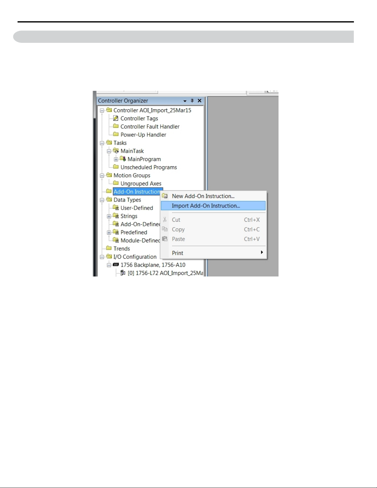
Open RSLogix 5000/Logix Designer and right-click on “Add-On Instructions” in the Controller Organizer tree then
select “Import Add-On Instruction…”
Figure 1 Import Add-On Instruction in the Controller Organizer Tree
Refer to AOI Selection on page 17 to select the correct AOI based on the application.
2.
NOTICE: Use the correct AOI. Using incorrect AOI could result in incorrectly mapped data or AOI set-up problems.
6
YASKAWA TOEP YAICOM 21A Logix Add-On Instruction (AOI) User Guide
Page 7
3 Importing AOI
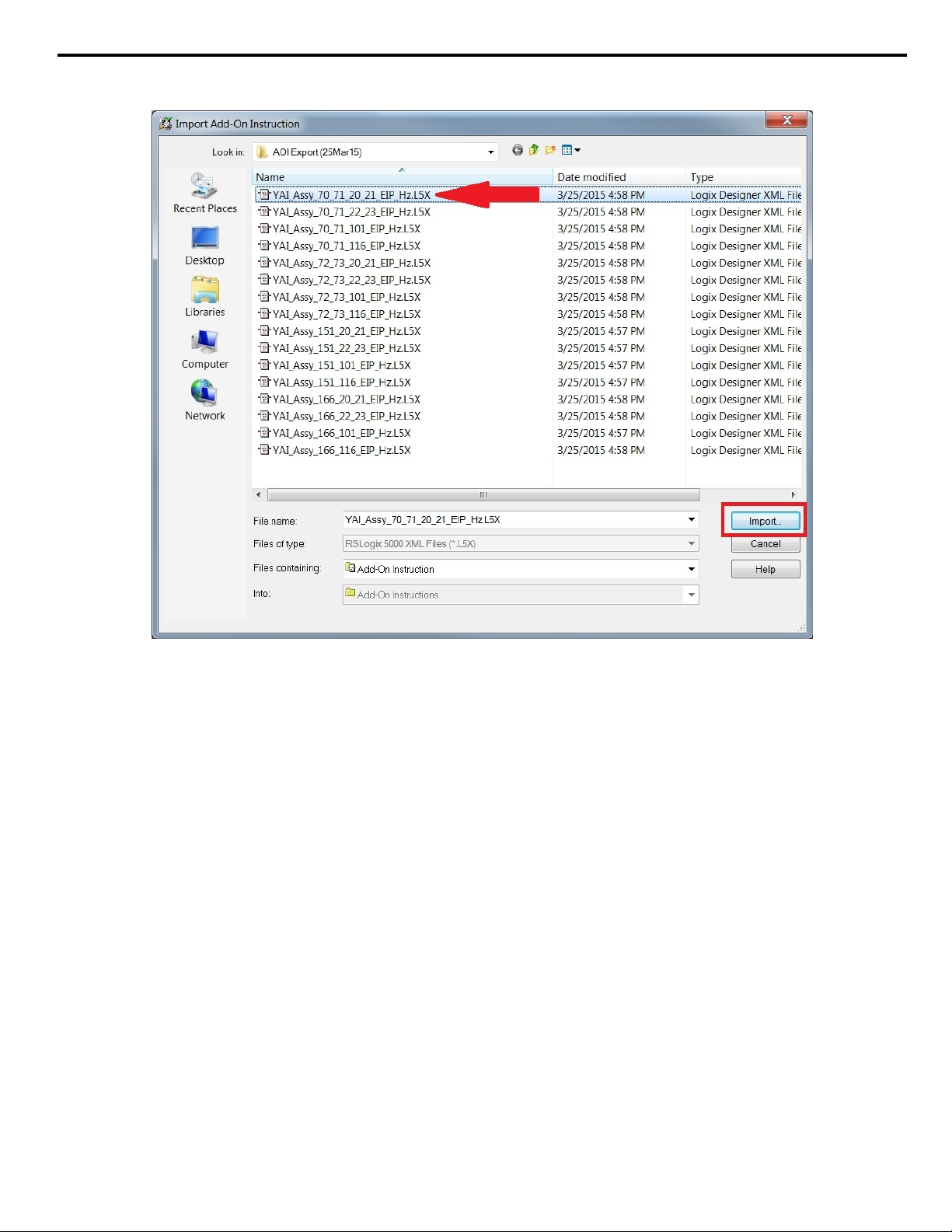
Navigate to the unzipped file directory from Step 1, select the AOI file and click the “Import…” button as shown in
3.
Figure 2.
Figure 2 Import the AOI File
YASKAWA TOEP YAICOM 21A Logix Add-On Instruction (AOI) User Guide
7
Page 8

3 Importing AOI
The ”Import Configuration” window will display the AOI import properties and notify the user of any warnings or errors.
4.
Click “OK” in the “Import Configuration” window.
Figure 3 Import Configuration Window
The imported AOI now appears under the “Add-On Instructions” folder of the Controller Organizer tree.
5.
Figure 4 Imported AOI in the Controller Organizer Tree
8
YASKAWA TOEP YAICOM 21A Logix Add-On Instruction (AOI) User Guide
Page 9

4 Setting Up the AOI
Click on file name
displayed here
This is the file name shown
in the “Add-On” Tab
Incorporate the imported AOI into the Logix program.
1.
Either drag and drop the file from the Controller Organizer tree as shown in Figure 5.
4 Setting Up the AOI
Figure 5 Drag the AOI from the Toolbar into the Program
Or click on the file name in the “Add-On” tab as shown in Figure 6.
Figure 6 Click on the the AOI in the Add-On Tab
YASKAWA TOEP YAICOM 21A Logix Add-On Instruction (AOI) User Guide
9
Page 10

4 Setting Up the AOI
Define a tag for the AOI.
2.
Click on the “?” next to the “...” button on the tag for which the AOI should be assigned.
Figure 7 Define the Tag
Note: The assigned tag name will be used throughout the program and should reflect the application. For example, the name
“Chilled_Water_Pump_01” would be appropriate for an application where the drive operates a chilled water pump.
In this procedure, the example assigned name will be “AOI_Name” as shown in Figure 8.
When the tag assigned to the AOI does not exist, proceed to Step 3 to create a new variable.
If the tag assigned to the AOI already exists, skip to Step 5.
Figure 8 Assign the Tag Name
10
YASKAWA TOEP YAICOM 21A Logix Add-On Instruction (AOI) User Guide
Page 11

4 Setting Up the AOI
Right-click on the tag (“AOI_Name” in this example), then select “New 'AOI_Name'” as shown in Figure 9to bring up
3.
the “New Tag” window.
Figure 9 Create a New Variable
YASKAWA TOEP YAICOM 21A Logix Add-On Instruction (AOI) User Guide
11
Page 12

4 Setting Up the AOI
The information shown in the “New Tag” window will define the new tag.
4.
Confirm the information as shown in Figure 10 and click “Create”.
Figure 10 New Tag Window
12
YASKAWA TOEP YAICOM 21A Logix Add-On Instruction (AOI) User Guide
Page 13

4 Setting Up the AOI
Direct the AOI to where it will read and write data.
5.
Note: The Yaskawa drive must be added to the I/O configuration prior to determining AOI read and write locations. Refer to application
note AN.AFD.09 for details on adding Yaskawa drives into Logix. AN.AFD.09 is posted on the Yaskawa website,
www.yaskawa.com.
Cick the “?” next to “Node_Input_Assy” as shown in Figure 11 to assign the input assembly (from drive to PLC) data.
Figure 11 Assign the Input Assembly
YASKAWA TOEP YAICOM 21A Logix Add-On Instruction (AOI) User Guide
13
Page 14

4 Setting Up the AOI
Click the “?” next to “Node_Output_Assy” as shown in Figure 12 to assign the output assembly (PLC to drive) data.
NOTICE: If the “Node_Input_Assy” or “Node_Output_Assy” fields do not appear in the AOI block, the node has not yet been created.
The fields will automatically appear when the node is created.
Figure 12 Assign the Output Assembly
The AOI setup is now complete and the AOI is ready to be used in the program.
6.
Figure 13 Successfully Completed AOI
14
YASKAWA TOEP YAICOM 21A Logix Add-On Instruction (AOI) User Guide
Page 15

5 Using the AOI
The following sections outline the more useful features of the AOI.
u
Creating Tags
When the AOI is implemented it will automatically create additional tags for use in the PLC logic.
5 Using the AOI
Figure 14 Tags Associated with AOI Names YAI_Assy_70_71_20_21_EIP_Hz
YASKAWA TOEP YAICOM 21A Logix Add-On Instruction (AOI) User Guide
15
Page 16

5 Using the AOI
u
Test Run
The AOI can test run the motor to which it is connected and help verify communication to the desired drive prior to creating
any type of logic.
Observing the output bits of the AOI while online with the PLC allows users to view the status of the drive. The corresponding
tag displays green when the bit is high.
Users can also enter values into the AOI to send commands through the function block.
For example, enter a value of “1” in the “RunFwd” section to send a forward run command to the drive, and it will set the
forward run command bit high. The “RunningFwd” output bit then turns green to indicate that the drive is running.
Figure 15 Test Run Information on AOI Block
u
Troubleshooting
The AOI block can help troubleshoot communications between the PLC and drive.
The AOI block will display the status of the AOI tags being used. The block displays the command being issued to the drive
and the drive status information being received from the drive.
16
Figure 16 AOI Block Displaying Status
YASKAWA TOEP YAICOM 21A Logix Add-On Instruction (AOI) User Guide
Page 17

6 AOI Selection
Use Table 1 to select the proper AOI based on Input and Output Assemblies.
Table 1 AOI Selection Table
Input Assembly Output Assembly Correct AOI
70 or 71 20 or 21 YAI_Assy_70_71_20_21_EIP_Hz
70 or 71 22 or 23 YAI_Assy_70_71_22_23_EIP_Hz
70 or 71 101 YAI_Assy_70_71_101_EIP_Hz
70 or 71 116 YAI_Assy_70_71_116_EIP_Hz
72 or 73 20 or 21 YAI_Assy_72_73_20_21_EIP_Hz
72 or 73 22 or 23 YAI_Assy_72_73_22_23_EIP_Hz
72 or 73 101 YAI_Assy_72_73_101_EIP_Hz
72 or 73 116 YAI_Assy_72_73_116_EIP_Hz
151 20 or 21 YAI_Assy_151_20_21_EIP_Hz
151 22 or 23 YAI_Assy_151_22_23_EIP_Hz
151 101 YAI_Assy_151_101_EIP_Hz
151 116 YAI_Assy_151_116_EIP_Hz
166 20 or 21 YAI_Assy_166_20_21_EIP_Hz
166 22 or 23 YAI_Assy_166_22_23_EIP_Hz
166 101 YAI_Assy_166_101_EIP_Hz
166 116 YAI_Assy_166_116_EIP_Hz
6 AOI Selection
YASKAWA TOEP YAICOM 21A Logix Add-On Instruction (AOI) User Guide
17
Page 18

7 AOI Data Tag Description
7 AOI Data Tag Description
Table 2 gives descriptions of tags found in the various AOIs.
Table 2 AOI Data Tags
Tag Description
Alarm Drive is in an alarm (not faulted) state.
Analog_Input_1_Level Signal level of analog input 1 (AI1) in %.
Analog_Output_1 Signal level of analog output 1 (AO1) in %.
Analog_Output_2 Signal level of analog output 2 (AO2) in %.
At_Speed Drive output frequency is at the level set by frequency reference.
Custom_In_1 Data read from custom data defined by F7-33.
Custom_In_1_Error Error reading custom data defined by F7-33.
Custom_In_10 Data read from custom data defined by F7-42.
Custom_In_10_Error Error reading custom data defined by F7-42.
Custom_In_2 Data read from custom data defined by F7-34.
Custom_In_2_Error Error reading custom data defined by F7-34.
Custom_In_3 Data read from custom data defined by F7-35.
Custom_In_3_Error Error reading custom data defined by F7-35.
Custom_In_4 Data read from custom data defined by F7-36.
Custom_In_4_Error Error reading custom data defined by F7-36.
Custom_In_5 Data read from custom data defined by F7-37.
Custom_In_5_Error Error reading custom data defined by F7-37.
Custom_In_6 Data read from custom data defined by F7-38.
Custom_In_6_Error Error reading custom data defined by F7-38.
Custom_In_7 Data read from custom data defined by F7-39.
Custom_In_7_Error Error reading custom data defined by F7-39.
Custom_In_8 Data read from custom data defined by F7-40.
Custom_In_8_Error Error reading custom data defined by F7-40.
Custom_In_9 Data read from custom data defined by F7-41.
Custom_In_9_Error Error reading custom data defined by F7-41.
Custom_Out_1 Data to be written to custom data defined by F7-23.
Custom_Out_1_Error Error writing to custom data defined by F7-23.
Custom_Out_10 Data to be written to custom data defined by F7-32.
Custom_Out_10_Error Error writing to custom data defined by F7-24.
Custom_Out_2 Data to be written to custom data defined by F7-24.
Custom_Out_2_Error Error writing to custom data defined by F7-25.
Custom_Out_3 Data to be written to custom data defined by F7-25.
Custom_Out_3_Error Error writing to custom data defined by F7-26.
Custom_Out_4 Data to be written to custom data defined by F7-26.
Custom_Out_4_Error Error writing to custom data defined by F7-27.
Custom_Out_5 Data to be written to custom data defined by F7-27.
Custom_Out_5_Error Error writing to custom data defined by F7-28.
Custom_Out_6 Data to be written to custom data defined by F7-28.
Custom_Out_6_Error Error writing to custom data defined by F7-29.
Custom_Out_7 Data to be written to custom data defined by F7-29.
Custom_Out_7_Error Error writing to custom data defined by F7-30.
Custom_Out_8 Data to be written to custom data defined by F7-30.
Custom_Out_8_Error Error writing to custom data defined by F7-31.
Custom_Out_9 Data to be written to custom data defined by F7-31.
Custom_Out_9_Error Error writing to custom data defined by F7-32.
DC_Bus_Volt Drive DC bus voltage in Vdc.
18
YASKAWA TOEP YAICOM 21A Logix Add-On Instruction (AOI) User Guide
Page 19

7 AOI Data Tag Description
Tag Description
Digital_Output_1 Digital output one status (M1-M2).
Digital_Output_2 Digital output two status (M3-M4).
Digital_Output_3 Digital output three status (M5-M6).
Digital_Output_Fault Digital output status of the fault contact (MA-MB-MC).
Digital_Output_Fault_Enable Bit to enable to the ability to control the fault contact via the network.
Drive_State Status code of the drive state.
Error_Code Custom data error code provides additional information on the cause of the custom error bit.
External_Fault Activating this bit will trigger an EF0 fault in the drive.
Faulted Drive is in a faulted state.
FaultReset Activating this bit will reset a fault in the drive (if resettable).
Freq_Cmd Commanded frequency reference from the network.
Freq_Ref Frequency reference command that is sent to the drive via the network.
MFI_3 Activating this bit will execute the function programmed for S3.
MFI_4 Activating this bit will execute the function programmed for S4.
MFI_5 Activating this bit will execute the function programmed for S5.
MFI_6 Activating this bit will execute the function programmed for S6.
MFI_7 Activating this bit will execute the function programmed for S7.
MFI_8 Activating this bit will execute the function programmed for S8.
MFO_1 Activating this bit will change the status of multi-function output 1 (M1-M2).
MFO_1_Status Status of multi-function output 1 (M1-M2).
MFO_2 Activating this bit will change the status of multi-function output 2 (M3-M4).
MFO_2_Status Status of multi-function output 2 (M3-M4).
MFO_3 Activating this bit will change the status of multi-function output 3 (M5-M6).
MFO_3_Status Status of multi-function output 3 (M5-M6).
Motor_Rated_Torq
Motor_Speed Motor output speed in Hz.
Net_Control
Net_Ref
NetCtrlStatus Bit is active if start/stop control is through the network.
NetRefStatus Bit is active if the speed reference is through the network.
Node_Input_Assy Input assembly data fed into the AOI. Define this data for the AOI to operate.
Node_Output_Assy Output assembly data fed into the AOI. Define this data for the AOI to operate.
OPE oPE alarm is present in the drive.
Output_Current Output current of the drive in amps.
Output_Freq Output frequency of the drive in Hz.
PG_Count Encoder feedback counter. The value in quadrature counts of the encoder.
Ready Drive is in the ready state.
Reset Fault reset to the drive is active.
RunFwd Activate the bit to run the drive in the forward direction.
Running Drive is in run mode.
RunningFwd Drive is running in the forward direction.
RunningRev Drive is running in the reverse direction.
RunRev Activate the bit to run the drive in the reverse direction.
Torq_Ref_Limit Torque reference or limit that is being sent to the drive. Scaled by Motor_Rated_Torq.
Torque_Actual Torque value (U1-09) from that drive. Scaled by Motor_Rated_Torq.
UV Drive is in an under voltage condition.
Warning Drive is in a warning (alarm) state.
ZSP Drive is currently at zero speed.
ZSV Zero servo is activated in the drive.
Motor rated torque as defined by the motor. Enter this value to scale the torque command. Enter “100.0”
for a range of 0-100.0%.
Activate the bit if start/stop control is desired through the network when b1-02 ≠ 3.
Activate the bit if speed reference control is desired through the network when b1-03 ≠ 3.
YASKAWA TOEP YAICOM 21A Logix Add-On Instruction (AOI) User Guide
19
Page 20

Revision History
MANUAL NO.
Example:
TOEP YAICOM 21A
Published in USA May 2015 15-5
Date of publication
Date of original publication
The revision dates and the numbers of the revised manuals appear on the bottom of the back cover.
Date of Publication
Revision
Number
Section Revised Content
May 2015 - - First Edition. This manual supports software version 2.0.0.
20
YASKAWA TOEP YAICOM 21A Logix Add-On Instruction (AOI) User Guide
Page 21

Page 22

Add-On Instruction (AOI)
for Logix Designer/RSLogix 5000
User Guide
YASKAWA AMERICA, INC.
2121 Norman Drive South, Waukegan, IL 60085, U.S.A.
Phone: (800) YASKAWA (927-5292) or 1-847-887-7000 Fax: 1-847-887-7310
http://www.yaskawa.com
YASKAWA ELÉTRICO DO BRASIL LTDA.
Avenida Piraporinha 777, Diadema, São Paulo, 09950-0000, Brasil
Phone: 55-11-3585-1100
http://www.yaskawa.com.br
YASKAWA CANADA, INC.
298 Avenue Labrosse, Pointe-Claire, Quebec H9R 5L8, Canada
Phone: (800) 854-4124 or 1-514-693-6770 Fax: 1-514-693-9212
http://www.yaskawa.com
Fax: 55-11-3585-1187
YASKAWA AMERICA, INC.
In the event that the end user of this pro duct i s to be the military and said product is to be employed in any weapons system s or the manufactur e
thereof, the export will fall under t he relevant regulatio ns as stipulated in the Foreign Exchange and Foreign Trade Regula tions. Therefore, be sure
to follow all procedures and s ubmit all relevant documentation ac cording to any and all ru les, regula tions and laws that may ap ply.
Specifications are subject to change without notice for ongoing product modifications and improveme nts.
© 2015 YASKAWA AMERICA, INC. All rights reserved.
MANUAL NO. TOEP YAICOM 21A
Published in USA May 2015 15-5
 Loading...