

Page 1

YASKAWA AC Drive Option
Analog Monitor
Installation Manual
Type
AO-A3
To properly use the product, read this manual thoroughly and retain
for easy reference, inspection, and maintenance. Ensure the end user
receives this manual.
安川インバータオプション
アナログモニタ
取扱説明書
形式
AO-A3
製品を安全にお使いいただくために,この取扱説明書を必ずお読みください。
また,本書をお手元に保管していただくとともに,最終的に本製品をご使用になる
ユーザー様のお手元に確実に届けられるよう,お取り計らい願います。
MANUAL NO. TOBP C730600 79C
Page 2

Copyright © 2016 YASKAWA ELECTRIC CORPORATION
All rights reserved. No part of this publication may be reproduced, stored in a retrieval system, or
transmitted, in any form or by any means, mechanical, electronic, photocopying, recording, or otherwise,
without the prior written permission of Yaskawa. No patent liability is assumed with respect to the use of the
information contained herein. Moreover, because Yaskawa is constantly striving to improve its high-quality
products, the information contained in this manual is subject to change without notice. Every precaution has
been taken in the preparation of this manual. Yaskawa assumes no responsibility for errors or omissions.
Neither is any liability assumed for damages resulting from the use of the information contained in this
publication.
2 YASKAWA ELECTRIC TOBP C730600 79C YASKAWA AC Drive Option AO-A3 Installation Manual
Page 3

Table of Contents
1 PREFACE AND SAFETY . . . . . . . . . . . . . . . . . . . . . . . . . . .4
2 OVERVIEW . . . . . . . . . . . . . . . . . . . . . . . . . . . . . . . . . . . . . . 8
3 RECEIVING. . . . . . . . . . . . . . . . . . . . . . . . . . . . . . . . . . . . . . 9
4 OPTION COMPONENTS . . . . . . . . . . . . . . . . . . . . . . . . . .10
5 INSTALLATION PROCEDURE . . . . . . . . . . . . . . . . . . . . .11
6 RELATED PARAMETERS . . . . . . . . . . . . . . . . . . . . . . . . .30
7 TROUBLESHOOTING . . . . . . . . . . . . . . . . . . . . . . . . . . . . 32
8 EUROPEAN STANDARDS. . . . . . . . . . . . . . . . . . . . . . . . . 35
9 SPECIFICATIONS . . . . . . . . . . . . . . . . . . . . . . . . . . . . . . . 37
YASKAWA ELECTRIC TOBP C730600 79C YASKAWA AC Drive Option AO-A3 Installation Manual 3
Page 4

1 Preface and Safety
1 Preface and Safety
YASKAWA Electric supplies component parts for use in a wide variety of industrial
applications. The selection and application of YASKAWA products remain the responsibility
of the equipment designer or end user.
YASKAWA accepts no responsibility for the way its products are incorporated into the final
system design. Under no circumstances should any YASKAWA product be incorporated into
any product or design as the exclusive or sole safety control. Without exception, all controls
should be designed to detect faults dynamically and fail safely under all circumstances. All
products designed to incorporate a component part manufactured by YASKAWA must be
supplied to the end user with appropriate warnings and instructions as to the safe use and
operation of that part. Any warnings provided by YASKAWA must be promptly provided to
the end user. YASKAWA offers an express warranty only as to the quality of its products in
conforming to standards and specifications published in the manual. NO OTHER
WARRANTY, EXPRESS OR IMPLIED, IS OFFERED. YASKAWA assumes no liability
for any personal injury, property damage, losses, or claims arising from misapplication of its
products.
u Applicable Documentation
The following manuals are available for the option:
Analog Monitor AO-A3 Option
YASKAWA AC Drive Option
Analog Monitor AO-A3
Installation Manual
Manual No: TOBP C730600 79
(This book)
This guide is packaged together with the product and contains
information necessary to install the option and set related drive
parameters.
Yaskawa Drive
Drive manuals contain basic installation and wiring information
in addition to detailed parameter setting, fault diagnostic, and
maintenance information.
YASKAWA AC Drive
Manuals
4 YASKAWA ELECTRIC TOBP C730600 79C YASKAWA AC Drive Option AO-A3 Installation Manual
The most recent versions of these manuals are available for
download on our documentation websites:
U.S.: http://www.yaskawa.com
Europe: http://www.yaskawa.eu.com
Japan: http://www.e-mechatronics.com
Other areas: Check the back cover of these manuals.
Page 5

1 Preface and Safety
DANGER
u Terms
Note: Indicates supplemental information that is not related to safety messages
Option: YASKAWA AC Drive Option Analog Monitor AO-A3
Drive: • YASKAWA A1000-Series Drive
Digital Operator: • LCD Operator for YASKAWA AC Drive 1000-Series
Energy-Saving Unit:
• YASKAWA L1000A-Series Drive
• YASKAWA D1000 Series Power Regenerative Converter
• YASKAWA R1000 Series Power Regenerative Unit
• YASKAWA U1000-Series Drive
• YASKAWA U1000L-Series Drive
• YASKAWA AC Drive GA700
• YASKAWA AC Drive CR700
• YASKAWA AC Drive CH700
• YASKAWA AC Drive 1000-Series (A1000, L1000A, D1000, R1000, U1000, U1000L)
• LED Operator for YASKAWA AC Drive 1000-Series
• LCD Keypad for YASKAWA AC Drive GA700, CR700, and CH700
• LED Keypad for YASKAWA AC Drive GA700, CR700, and CH700
• YASKAWA D1000 Series Power Regenerative Converter
• YASKAWA R1000 Series Power Regenerative Unit
u Registered Trademarks
Trademarks are the property of their respective owners.
u Supplemental Safety Information
Read and understand this manual before installing, operating, or servicing this option. Install
the option according to this manual and local codes.
The following conventions indicate safety messages in this manual. Failure to heed these
messages could cause fatal injury or damage products and related equipment and systems.
Indicates a hazardous situation, which, if not avoided, will cause death or serious
injury.
YASKAWA ELECTRIC TOBP C730600 79C YASKAWA AC Drive Option AO-A3 Installation Manual 5
Page 6

1 Preface and Safety
W ARNING
CAUTION
NOTICE
DANGER
Indicates a hazardous situation, which, if not avoided, could cause death or serious
injury.
Indicates a hazardous situation, which, if not avoided, could cause minor or
moderate injury.
Indicates an equipment damage message.
n
General Safety
General Precautions
• The diagrams in this book may include options and drives without covers or safety shields to illustrate details. Be
sure to reinstall covers or shields before operating any devices. Use the option according to the instructions
described in this manual.
• The diagrams in this manual are provided as examples only and may not pertain to all products covered by this
manual.
• The products and specifications described in this manual or the content and presentation of the manual may be
changed without notice to improve the product and/or the manual.
• Contact a Yaskawa representative or the nearest Yaskawa sales office and provide the manual number shown on the
front cove to order new copies of the manual.
Heed the safety messages in this manual.
Failure to comply will cause death or serious injury.
The operating company is responsible for any injuries or equipment damage resulting
from failure to heed the warnings in this manual.
6 YASKAWA ELECTRIC TOBP C730600 79C YASKAWA AC Drive Option AO-A3 Installation Manual
Page 7

1 Preface and Safety
W ARNING
NOTICE
Electrical Shock Hazard
Do not attempt to modify or alter the drive or drive circuitry in any way not
explained in this manual.
Failure to comply could cause death or serious injury and will void warranty. Yaskawa is
not responsible for any modification of the product made by the user. Do not modify this
product.
Do not expose the drive or the option to halogen group disinfectants. Do not pack the
drive or the option in fumigated or sterilized wooden materials. Do not sterilize the
entire package after packing the product.
Failure to comply could damage electrical components in the option.
YASKAWA ELECTRIC TOBP C730600 79C YASKAWA AC Drive Option AO-A3 Installation Manual 7
Page 8

2 Overview
AO
2 Overview
The Analog Monitor Option AO-A3 allows the user to expand the number of available
analog outputs to monitor performance.
The option uses parameters and the output signal gain and bias to assign functions to output
terminals V1 and V2.
The option has two analog outputs, an 11-bit signed (1/2048) output resolution, and a
-10 to 10 Vdc non-isolated output voltage.
u Compatible Products
The option can be used with the products in Ta bl e 1 .
Table 1 Compatible Products
Product Series Model(s)
A1000 All models
L1000A All models
U1000 All models
U1000L All models
D1000 All models
R1000 All models
GA700 All models
CR700 All models
CH700 All models
Note: For Yaskawa customers in the North or South America region:
If your product is not listed in Table 1, refer to the web page below to confirm this manual is
correct for your product. The web page provides a list of option manuals by product, and a direct
link to download a PDF.
Scan QR code
Or refer to: http://www.yaskawa.com/optionlookup
8 YASKAWA ELECTRIC TOBP C730600 79C YASKAWA AC Drive Option AO-A3 Installation Manual
Page 9

3 Receiving
AO-A3
AO
MANUAL
3 Receiving
After receiving the option package:
1. Make sure that the option is not damaged and no parts are missing. Contact your sales
outlet if the option or other parts appear damaged.
NOTICE: Do not use damaged parts to connect the drive and the option. Failure to comply could damage
the drive and option.
2. Confirm that the model number on the option nameplate and the model listed in the
purchase order are the same. Refer to Figure 1 on page 10 for details. Contact the
distributor where the option was purchased or the Yaskawa sales office immediately about
any problems with the option.
u Option Package Contents
Description:
–
Quantity: 13
<1> GA700, CR700, and CH700 drives do not use the ground wire.
<2> GA700, CR700, and CH700 drives use two screws only.
Option Ground Wires
<1>
Screws (M3) Installation Manual
<2>
3
u Installation Tools
• A Phillips screwdriver. Phillips screw sizes vary by drive capacity.
• A flat-blade screwdriver (blade depth: 0.4 mm (0.02 in.), width: 2.5 mm (0.1 in.)).
• A pair of diagonal cutting pliers.
• A small file or medium-grit sandpaper.
Note: This manual does not list tools required to prepare option cables for wiring.
YASKAWA ELECTRIC TOBP C730600 79C YASKAWA AC Drive Option AO-A3 Installation Manual 9
1
Page 10

4 Option Components
AO
V1 AC V2 AC FE
AO
4 Option Components
u Analog Monitor AO-A3 Option
Figure 1
E
F
A
B
Underside
D
<1> Connect the provided ground wire during installation. Installation on GA700, CR700, and CH700 drives does not
require the ground wire.
<2> Do not adjust the potentiometers on the option. The potentiometers are factory set and may change the voltage
output characteristics and cause output signal inaccuracy if misadjusted.
AO-A3
C
A – Connector (CN5) D – Ground terminal (FE) and
B – Installation hole
C – Option model number E – Terminal Block TB1
Figure 1 Analog Monitor AO-A3 Option Components
installation hole
F–Potentiometers
<1>
<2>
u Terminal Block TB1
Refer to Table 5 on page 29 for details on TB1 terminal functions and signal levels.
10 YASKAWA ELECTRIC TOBP C730600 79C YASKAWA AC Drive Option AO-A3 Installation Manual
Page 11

5 Installation Procedure
DANGER
W ARNING
5 Installation Procedure
u Section Safety
Electrical Shock Hazard
Do not inspect, connect, or disconnect any wiring while the drive is energized.
Failure to comply will cause death or serious injury.
Before servicing, disconnect all power to the equipment and wait for at least the time
specified on the warning label. The internal capacitor remains charged even after the drive
is de-energized. The charge indicator LED will extinguish when the DC bus voltage is
below 50 Vdc. When all indicators are OFF, measure for unsafe voltages to confirm the
drive is safe.
Electrical Shock Hazard
Do not operate equipment with covers removed.
Failure to comply could cause death or serious injury.
The diagrams in this section may include options and drives without covers or safety
shields to illustrate details. Reinstall covers and shields before operating the drive and run
the drive according to the instructions described in this manual.
Do not allow unqualified personnel to perform work on the drive or option.
Failure to comply could cause death or serious injury.
Only authorized personnel familiar with installation, adjustment, and maintenance of AC
drives and options may perform work.
Do not remove covers or touch circuit boards while the drive is energized.
Failure to comply could cause death or serious injury.
YASKAWA ELECTRIC TOBP C730600 79C YASKAWA AC Drive Option AO-A3 Installation Manual 11
Page 12

5 Installation Procedure
NOTICE
W ARNING
Do not use damaged wires, stress the wiring, or damage the wire insulation.
Failure to comply could cause death or serious injury.
Fire Hazard
Tighten all terminal screws to the specified tightening torque.
Loose or overtightened connections could cause erroneous operation and damage to the
terminal block or start a fire and cause death or serious injury.
Damage to Equipment
Observe proper electrostatic discharge (ESD) procedures when handling the option,
drive, and circuit boards.
Failure to comply could cause ESD damage to circuitry.
Never connect or disconnect the motor from the drive while the drive is outputting
voltage.
Improper equipment sequencing could damage the drive.
Do not connect or operate any equipment with visible damage or missing parts.
Failure to comply could further damage the equipment.
Do not use unshielded wire for control wiring.
Failure to comply may cause electrical interference resulting in poor system performance.
Use shielded, twisted-pair wires and ground the shield to the ground terminal of the drive.
Properly connect all pins and connectors on the option and drive.
Failure to comply could prevent proper operation and damage equipment.
Confirm that all connections are correct after installing the option and connecting
peripheral devices.
Failure to comply could damage the option.
12 YASKAWA ELECTRIC TOBP C730600 79C YASKAWA AC Drive Option AO-A3 Installation Manual
Page 13

5 Installation Procedure
u Procedures for Installing and Wiring Options on a Drive
Procedures for installing and wiring options differ depending on the product.
Refer to Table 2 to check the procedures for installing and wiring options on a drive.
Table 2 Procedures for Installing and Wiring Options on a Drive
Product Series
A1000 Procedure A 14
L1000A Procedure A 14
U1000 Procedure A 14
U1000L Procedure A 14
GA700 Procedure B 21
CR700 Procedure B 21
CH700 Procedure B 21
Procedures for Installing and
Wiring Options on a Drive
Page
YASKAWA ELECTRIC TOBP C730600 79C YASKAWA AC Drive Option AO-A3 Installation Manual 13
Page 14

5 Installation Procedure
E
G
L
K
J
I
H
B
A
C
D
F
n
Procedure A
This section describes the procedure for installing and wiring options on 1000-series drives.
Prepare the Drive for the Option
Before beginning the installation procedure:
1. Wire the drive and make the proper connections to drive terminals according to the manual
packaged with the drive.
2. Verify that the drive functions normally.
Refer to Figure 2 for an exploded view of the drive with the option and related components
for reference in the installation procedure.
Figure 2
A – Insertion point for CN5 G – Included screws
B – Option card H – Ground wire
C – Front cover I – Drive grounding terminal (FE)
D – Digital operator J – Connector CN5-A
E – Terminal cover K – Connector CN5-B
F – Removable tabs for wire routing L – Connector CN5-C
14 YASKAWA ELECTRIC TOBP C730600 79C YASKAWA AC Drive Option AO-A3 Installation Manual
Figure 2 Drive Components with Option
Page 15

5 Installation Procedure
Install the Option
Refer to the instructions below to install the option.
DANGER! Electrical Shock Hazard. Do not inspect, connect, or disconnect any wiring while the drive is
energized. Failure to comply will cause death or serious injury. Before servicing, disconnect all power to the
equipment and wait for at least the time specified on the warning label. The internal capacitor remains
charged even after the drive is de-energized. The charge indicator LED will extinguish when the DC bus
voltage is below 50 Vdc. When all indicators are OFF, measure for unsafe voltages to confirm the drive is
safe.
1.
Shut off power to the drive, wait the appropriate amount of time for voltage to
dissipate, then remove the digital operator (D) and front covers (C, E).
Refer to the manual packaged with the drive for details on digital operator and cover
removal.
NOTICE: Damage to Equipment. Observe proper electrostatic discharge (ESD) procedures when handling
the option, drive, and circuit boards. Failure to comply could cause ESD damage to circuitry.
Figure 3
C
D
E
Figure 3 Remove the Digital Operator, Front Cover, and Terminal Cover
YASKAWA ELECTRIC TOBP C730600 79C YASKAWA AC Drive Option AO-A3 Installation Manual 15
Page 16

5 Installation Procedure
J
G
B
K
L
2.
Insert the option card (B) into the CN5-A (J), CN5-B (K), or CN5-C (L) connector on
the drive and fasten it into place using one of the included screws (G). Tighten both
screws to 0.5 to 0.6 Nm (4.4 to 5.3 in. lbs).
Figure 4
Figure 4 Insert the Option Card
16 YASKAWA ELECTRIC TOBP C730600 79C YASKAWA AC Drive Option AO-A3 Installation Manual
Page 17

5 Installation Procedure
I
G
H
B
3.
Connect one end of the ground wire (H) to the ground terminal (I) using one of the
remaining provided screws (G). Connect the other end of the ground wire (H) to the
remaining ground terminal and installation hole on the option (B) using the last
remaining provided screw (G). Tighten both screws to 0.5 to 0.6 Nm (4.4 to 5.3 in.
Figure 5
lbs).
Figure 5 Connect the Ground Wire
Note: 1. The option package includes three ground wires. Use the longest wire to connect the option to CN5-C.
Use the next longest wire to connect the option to CN5-B. Use the shortest wire to connect the option to
CN5-A. Refer to Option Package Contents on page 9 for more information.
2. The drive has only two ground terminal screw holes (I). Two ground wires should share the same
ground terminal when connecting three options.
YASKAWA ELECTRIC TOBP C730600 79C YASKAWA AC Drive Option AO-A3 Installation Manual 17
Page 18

5 Installation Procedure
Insulation
Shield sheath
Option terminal
To customer
circuit
FE
(Insulate with electrical tape
or heat-shrink tubing)
AO
Option terminal block
Preparing wire ends:
Screwdriver blade size
about 5.5 mm (7/32”)
When not using
crimped insulated
sleeves
Pull back the shielding and lightly
twist the end with fingers, keeping
the ends from fraying.
Wire crimping ferrule terminals
or not soldered ends
Loosen the screws and
insert the wire into the
opening on the terminal block.
Blade depth of
0.4 mm or less
Blade width of
2.5 mm or less
AO
4.
Prepare and connect the wire ends as shown in Figure 6 and Figure 7. Refer to
Wire Gauges and Tightening Torques on page 28 to confirm that the proper
tightening torque is applied to each terminal. Take particular precaution to ensure
that each wire is properly connected and wire insulation is not accidentally pinched
into electrical terminals.
WARNING! Fire Hazard. Tighten all terminal screws according to the specified tightening torque. Loose
electrical connections could result in death or serious injury by fire due to overheating electrical connections.
Tightening screws beyond the specified tightening torque may cause erroneous operation, damage the
terminal block, or cause a fire.
NOTICE: Heat shrink tubing or electrical tape may be required to ensure that cable shielding does not
contact other wiring. Insufficient insulation may cause a short circuit and damage the option or drive.
Figure 6
Figure 6 Prepare Ends of Shielded Cable
5.
Wire the customer-supplied circuit to the terminal block on the option according to
Figure 7. Refer to Figure 17 for the AO-A3 Option connection diagram. Refer to
Figure 7
Table 5 for a detailed description of the option terminal functions.
18 YASKAWA ELECTRIC TOBP C730600 79C YASKAWA AC Drive Option AO-A3 Installation Manual
Figure 7 Connect Cable Wiring
Page 19

Figure 8
A
B
5 Installation Procedure
6.
Route the option wiring inside the enclosure as shown in Figure 8-B. Take proper
precautions so that the front covers will easily fit back onto the drive.
Users may also choose to route the option wiring through openings on the front
cover of some models. Remove the perforated tabs on the left side of the front cover
as shown in Figure 8-A to create the necessary openings on these models.
Refer to the Peripheral Devices & Options section of the drive instruction manual for
more information.
Figure 8 Wire Routing Examples
YASKAWA ELECTRIC TOBP C730600 79C YASKAWA AC Drive Option AO-A3 Installation Manual 19
Page 20

5 Installation Procedure
C
D
E
7.
Replace and secure the front covers of the drive (C, E) and replace the digital
operator (D).
NOTICE: Do not pinch cables between the front covers and the drive. Failure to comply could cause
erroneous operation.
Figure 9
Figure 9 Replace the Front Covers and Digital Operator
8.
Set drive parameters in Table 6 for proper option performance.
20 YASKAWA ELECTRIC TOBP C730600 79C YASKAWA AC Drive Option AO-A3 Installation Manual
Page 21

5 Installation Procedure
C
I
F
H
G
B
A
D
E
AO
n
Procedure B
This section describes the procedure for installing and wiring options on GA700, CR700,
and CH700 drives.
Prepare the Drive for the Option
Before beginning the installation procedure:
1. Wire the drive and make the proper connections to drive terminals according to the manual
packaged with the drive.
2. Verify that the drive functions normally.
Refer to Figure 10 for an exploded view of the drive with the option and related
components for reference in the installation procedure.
Figure 10
A – Insertion point for CN5 connector F – LED Status Ring board
B – AO-A3 option G – Connector CN5-A
C – Included screws H – Connector CN5-B
D – Drive front cover I – Connector CN5-C
E – Keypad
YASKAWA ELECTRIC TOBP C730600 79C YASKAWA AC Drive Option AO-A3 Installation Manual 21
Figure 10 Drive Components with Option
Page 22

5 Installation Procedure
Keypad connector
Keypad connector tab
Move the keypad connector to the holder on the
drive after removing the keypad and before removing
the front cover. Insert the keypad connector tab into
the holder when installing the keypad connector to
the holder.
Holder
D
E
AO
Install the Option
DANGER! Electrical Shock Hazard. Do not inspect, connect, or disconnect any wiring while the drive is
energized. Failure to comply will cause death or serious injury. Before servicing, disconnect all power to the
equipment and wait for at least the time specified on the warning label. The internal capacitor remains
charged even after the drive is de-energized. The charge indicator LED will extinguish when the DC bus
voltage is below 50 Vdc. When all indicators are OFF, measure for unsafe voltages to confirm the drive is
safe.
1.
Shut off power to the drive, wait the appropriate amount of time for voltage to
dissipate, confirm all charge indicator LEDs extinguish, then remove the front cover
(D) including the keypad (E).
Refer to the manual packaged with the drive for details on cover removal.
NOTICE: Observe proper electrostatic discharge (ESD) procedures when handling the option, drive, and
circuit boards. Failure to comply could cause ESD damage to circuitry.
Figure11
22 YASKAWA ELECTRIC TOBP C730600 79C YASKAWA AC Drive Option AO-A3 Installation Manual
Figure 11 Remove the Front Cover Including Keypad
Page 23

5 Installation Procedure
AO
2.
Carefully remove the LED Status Ring board (F) and place it on the right side of the
drive using the temporary placement holes.
Refer to the manual packaged with the drive for details on removing the LED Status
Ring board.
NOTICE: Do not remove the LED Status Ring board cable connector. Failure to comply could cause
erroneous operation and damage the drive.
Figure 12
F
Temporary placement holes
Drive front view
Figure 12 Remove the LED Status Ring Board
YASKAWA ELECTRIC TOBP C730600 79C YASKAWA AC Drive Option AO-A3 Installation Manual 23
Page 24

5 Installation Procedure
C
I
H
G
B
A
AO
Insulation
Shield sheath
Option terminal
To customer
circuit
FE
(Insulate with electrical tape
or heat-shrink tubing)
AO
3.
Insert the option card (B) into the CN5-A (G), CN5-B (H) and CN5-C (I) connector
on the drive and fasten it into place using the included screws (C). Tighten both
Figure 13
Figure 14
screws to 0.5 to 0.6 Nm (4.4 to 5.3 in. lbs).
Figure 13 Insert the Option Card
Note: Installing the option card on a GA700, CR700, and CH700 drive requires only two screws and
does not require a ground wire. The option package ships with three screws and ground wires for
installation on other product series. Do not use the ground wire or the extra screw.
4.
Prepare the wire ends as shown in Figure 14.
Figure 14 Prepare Ends of Shielded Cable
24 YASKAWA ELECTRIC TOBP C730600 79C YASKAWA AC Drive Option AO-A3 Installation Manual
Page 25

Figure 15
Option terminal block
Preparing wire ends:
Screwdriver blade size
about 5.5 mm (7/32”)
When not using
crimped insulated
sleeves
Pull back the shielding and lightly
twist the end with fingers, keeping
the ends from fraying.
Wire crimping ferrule terminals
or not soldered ends
Loosen the screws and
insert the wire into the
opening on the terminal block.
Blade depth of
0.4 mm or less
Blade width of
2.5 mm or less
AO
5 Installation Procedure
5.
Wire the customer-supplied circuit to the terminal block on the option according to
Figure 15. Refer to Figure 17 for the AO-A3 Option connection diagram. Refer to
Table 5 for a detailed description of the option terminal functions.
Figure 15 Connect Cable Wiring
YASKAWA ELECTRIC TOBP C730600 79C YASKAWA AC Drive Option AO-A3 Installation Manual 25
Page 26

5 Installation Procedure
F
Install the keypad to the drive after replacing
the keypad connector and then the keypad
connector. At that time, insert the keypad
connector tab into the drive.
Keypad
connector
Ta b
D
E
AO
6.
Replace and secure the LED Status Ring board (F) and the front cover of the drive
Figure 16
(D) including the keypad (E).
Figure 16 Replace the LED Status Ring Board, Front Cover, and Keypad
26 YASKAWA ELECTRIC TOBP C730600 79C YASKAWA AC Drive Option AO-A3 Installation Manual
Page 27

5 Installation Procedure
AO
Replace and secure the LED Status Ring board (F).
Use the open space provided inside the LED Status Ring board to route option
wiring when using connector CN5-B.
NOTICE: Do not pinch cables between the front cover or the LED Status Ring board and the drive. Failure
to comply could cause erroneous operation.
Use the open space provided
inside the LED Status Ring
board to route option wiring.
F
7.
Set drive parameters in Table 6 for proper option performance.
YASKAWA ELECTRIC TOBP C730600 79C YASKAWA AC Drive Option AO-A3 Installation Manual 27
Page 28

5 Installation Procedure
Twisted-pair shielded line
Main circuit terminal Control circuit terminal
V1
AC
AC
V2
FE <1>
AO-A3
Monitor
CN5
R/L1
S/L2
T/L3
TB1
FE <1>
FM
AM
+
−
+
−
Drive
AO
u Option Connection Diagram
Refer to Table 5 on page 29 for a detailed description of the option board terminal functions.
To ensure accurate control, use stable power supply for the voltage reference source.
<1> Connect the provided ground wire during installation on 1000-series drives. Installation on GA700, CR700, and
CH700 drives does not require the ground wire.
Figure 17 Option Connection Diagram
NOTICE: Do not adjust the potentiometers on the option. The potentiometers are factory set and may
change the voltage output characteristics and cause output signal inaccuracy if misadjusted.
u Wire Gauges, Tightening Torques and Ferrule-Type Terminals
n
Wire Gauges and Tightening Torques
Wire gauge and torque specifications are listed in Tab l e 3.
Table 3 Wire Gauges and Tightening Torques
Ter min al
signal
V1, V2,
AC, FE
28 YASKAWA ELECTRIC TOBP C730600 79C YASKAWA AC Drive Option AO-A3 Installation Manual
Tightening
Screw
Size
M2
Torque
Nm (inlb)
0.22 to 0.25
(1.95 to 2.21)
Bare Cable Ferrule-Type Terminals
Recomm.
Gauge mm
0.75
(18 AWG)
Applicable
2
Gauges mm
Stranded wire:
0.25 to 1.0
(24 to 17 AWG)
Solid wire:
0.25 to 1.5
(24 to 16 AWG)
Recomm.
2
Gauge mm
0.5
(20 AWG)
2
(24 to 20 AWG)
Applicable
Gauges mm
0.25 to 0.5
2
Shielded
pair, etc.
Wire
Typ e
twisted
Page 29
5 Installation Procedure
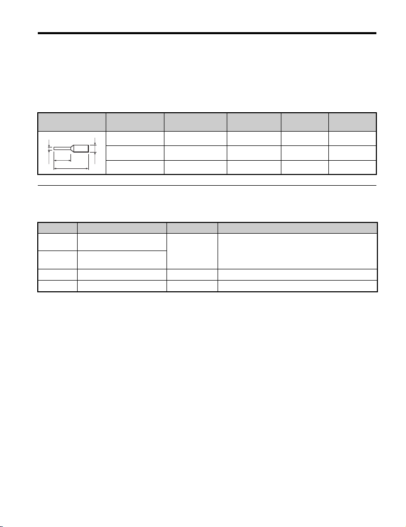
n
Ferrule-Type Terminals
Yaskawa recommends using CRIMPFOX 6 by Phoenix Contact or equivalent ferrule-type
terminals with the specifications listed in Table 4 for wiring to ensure proper connections.
Note: Properly trim wire ends so loose wire ends do not extend from the crimp terminals.
Table 4 Ferrule-Type Terminal Sizes
Ferrule-Type
Ter min al
6 mm
d1
L
Wire Gauge
mm
0.25 (24 AWG) AI 0.25 - 6YE 10.5 (13/32) 0.8 (1/32) 2 (5/64)
0.34 (22 AWG) AI 0.34 - 6TQ 10.5 (13/32) 0.8 (1/32) 2 (5/64)
d2
0.5 (20 AWG) AI 0.5 - 6WH 14 (9/16) 1.1 (3/64) 2.5 (3/32)
2
Phoenix Contact
Model
L
mm (in)
d1
mm (in)
d2
mm (in)
u Terminal Functions
Table 5 Option Terminal Functions
Ter min al Function Signal Level Description
V1
Analog voltage output 1
V2 Analog voltage output 2
AC Common 0 V Common for analog voltage output
FE Ground – Used for grounding shielded lines
<1> Set the functions and output levels for terminals V1 and V2 using drive parameters. See the drive Instruction
Manual for directions on setting parameters.
-10 to 10 V
• Analog voltage output for an external monitoring
<1>
device
• Output resolution 11-bit plus sign (1/2048)
• Max. load current 3 mA
YASKAWA ELECTRIC TOBP C730600 79C YASKAWA AC Drive Option AO-A3 Installation Manual 29
Page 30

6 Related Parameters
6 Related Parameters
The parameters outlined in the following sections are used to set up the drive for operation
with the option. Set parameters as needed. Refer to the manual packaged with the drive for
details on setting parameters.
u Parameter Table
“RUN” indicates that parameter can be changed during run.
Table 6 Related Parameters
No.
(Addr.
Hex)
F4-01
Terminal V1 Monitor Selection
(391)
<1>
F4-02
(392)
Terminal V1 Monitor Gain
RUN
F4-03
Terminal V2 Monitor Selection
(393)
<1>
F4-04
(394)
Terminal V2 Monitor Gain
RUN
F4-05
(395)
Terminal V1 Monitor Bias
RUN
F4-06
Terminal V2 Monitor Bias
(396)
F4-07
Terminal V1 Signal Level Select
(397)
F4-08
Terminal V2 Signal Level Select
(398)
Name Description Valu es
Default when installed
to drive: 102 (output
Sets the monitor signal for output from
terminal V1.
Sets the gain for voltage output via terminal
V1, where 100% equals 10 V output.
Sets the monitor signal for output from
terminal V2.
Sets the gain for voltage output via terminal
V2, where 100% equals 10 V output. Terminal
output voltage is limited to 10 V.
Sets the amount of bias added to the voltage
output via terminal V1.
Sets the amount of bias added to the voltage
output via terminal V2.
Sets the voltage level for the analog output.
0: 0 V to 10 V
1: -10 V to 10 V
<2>
<2>
<2>
frequency)
Default when installed
to energy-saving unit:
000 (reserved)
Range: 000 to 999
Default: 100.0%
Min: -999.9
Max: 999.9
Default when installed
to drive: 103 (output
voltage)
Default when installed
to energy-saving unit:
000 (reserved)
Range: 000 to 999
Default: 50.0%
Min: -999.9
Max: 999.9
Default: 0.0%
Min: -999.9
Max: 999.9
Default: 0.0%
Min: -999.9
Max: 999.9
Default: 0
Range: 0, 1
Default: 0
Range: 0, 1
30 YASKAWA ELECTRIC TOBP C730600 79C YASKAWA AC Drive Option AO-A3 Installation Manual
Page 31

6 Related Parameters
<1> A setting of 031 or 000 applies no drive monitor to the analog output. With this setting, terminal functions as well
as V1 and V2 output levels can be set by a PLC via a communication option or MEMOBUS/Modbus (through
mode).
<2> The drive outputs voltage while this parameter is being adjusted. Voltage levels can be adjusted to match the
specifications of an external meter.
YASKAWA ELECTRIC TOBP C730600 79C YASKAWA AC Drive Option AO-A3 Installation Manual 31
Page 32

7 Troubleshooting
7 Troubleshooting
u Drive-Side Error Codes
Table 7 lists the various fault codes related to the option. Refer to the drive instruction
manual for further details on fault codes.
Confirm the following items upon receiving an error notification on the drive digital
operator:
1. Correct and secure cable connections including ground wiring.
2. Proper option installation.
3. No momentary power loss occurred.
Table 7 Fault Displays, Causes, and Possible Solutions
Digital Operator Display Fault Name
oFA01 Option is not properly connected.
Cause Possible Solution
The option connected to option port CN5-A was
changed during run.
Digital Operator Display Fault Name
oFb01
Cause Possible Solution
Option in drive port CN5-B was changed during
run.
Digital Operator Display Fault Name
oFb02
Cause Possible Solution
Same type of option connected to ports
CN5-A and CN5-B.
Digital Operator Display Fault Name
oFC01 Option is not properly connected.
Cause Possible Solution
Option at drive port CN5-C was changed during
run.
De-energize the drive and plug the option into the drive
according to Installation Procedure on page 11.
Option Card Fault (CN5-B)
Option is not properly connected.
De-energize the drive and plug the option into the drive
according to Installation Procedure on page 11.
Option Fault (CN5-B)
Two identical options are connected at the same time.
Use only compatible options.
De-energize the drive and plug the option into the drive
according to Installation Procedure on page 11.
32 YASKAWA ELECTRIC TOBP C730600 79C YASKAWA AC Drive Option AO-A3 Installation Manual
Page 33

7 Troubleshooting
Digital Operator Display Fault Name
oFC02
Cause Possible Solution
Same type of option connected to unit ports
CN5-A, CN5-B, and CN5-C.
Option Fault (CN5-C)
Two identical options are connected at the same time.
Use only compatible options.
u Option Compatibility
Users may connect up to 3 options simultaneously depending on the type of option.
Refer to Table 8 for details.
Table 8 Option Compatibility
Option Card
PG-B3, PG-X3 CN5-B, C 2
PG-RT3
<2> <3>
, PG-F3
<2> <3>
DO-A3, AO-A3 CN5-A, B, C 1
SI-C3, SI-N3, SI-P3, SI-S3, SI-T3,
SI-ET3, AI-A3, DI-A3, SI-ES3,
SI-B3, SI-M3,
<3>
, SI-EM3
<3>
, SI-EN3
<3>
SI-W3
SI-EP3
<1> When connecting two PG option cards, use both CN5-B and CN5-C. When connecting only one PG option card,
use the CN5-C connector.
<2> Not available for the application with Motor 2 Selection.
<3> Not available with 1000-Series products with a capacities between 450 and 630 kW.
,
Connector Number of Cards Possible
<1>
CN5-C 1
CN5-A 1
u Preventing Electrical Signal Interference
Take the following steps to prevent erroneous operation caused by electrical signal
interference:
• Use shielded wire for the signal lines.
• Limit the length of wiring under 50 m (164 ft.).
• Separate the control wiring to the option, main circuit wiring, and power lines.
YASKAWA ELECTRIC TOBP C730600 79C YASKAWA AC Drive Option AO-A3 Installation Manual 33
Page 34

7 Troubleshooting
AO
n
Interface Circuit
Figure 17
Signal
processor
Figure 18 Output Interface Circuit
–
+
V1, V2
AC
34 YASKAWA ELECTRIC TOBP C730600 79C YASKAWA AC Drive Option AO-A3 Installation Manual
Page 35

8 European Standards
8 European Standards
Figure 18
Figure 19 CE Mark
The CE mark indicates compliance with European safety and environmental regulations. It
is required for engaging in business and commerce in Europe.
European standards include the Machinery Directive for machine manufacturers, the Low
Voltage Directive for electronics manufacturers, and the EMC guidelines for controlling
noise.
This option displays the CE mark based on the EMC guidelines.
EMC Guidelines: 2014/30/EU
Drives used in combination with this option and devices used in combination with the drive
must also be CE certified and display the CE mark. When using drives displaying the CE
mark in combination with other devices, it is ultimately the responsibility of the user to
ensure compliance with CE standards. Verify that conditions meet European standards after
setting up the device.
u EMC Guidelines Compliance
This option is tested according to European standards EN 61800-3:2004+A1:2012 and
complies with EMC guidelines. The CE marking is declared based on the harmonized
standards.
n
EMC Guidelines Installation Conditions
Verify the following installation conditions to ensure that other devices and machinery used
in combination with this option and drives also comply with EMC guidelines:
1.
Use dedicated shield cable for the option and external device (encoder, I/O device,
master), or run the wiring through a metal conduit.
2.
Keep wiring as short as possible and ground the largest possible surface area of the
shield to the metal panel according to Figure 21.
YASKAWA ELECTRIC TOBP C730600 79C YASKAWA AC Drive Option AO-A3 Installation Manual 35
Page 36

8 European Standards
A1
Figure 19
A
CB
A – Braided shield cable C – Cable clamp (conductive)
B–Metal panel
Figure 20 Ground Area
n
Option Installation for CE Compliance: Models PG-, DI-, DO-,
AI-, AO-, SI-
Figure 20
Enclosure panel
Threephase
power
supply
EMC filter PG option
L1
L2
L3
L1
L2
L3
R
S
T
CN5-B,
CN5-C
PG-
I/O option
Drive
CN5-A,
CN5-B,
CN5-C
CN5-A
Figure 21 Option Installation for CE Compliance
36 YASKAWA ELECTRIC TOBP C730600 79C YASKAWA AC Drive Option AO-A3 Installation Manual
DI-,
DO-,
AI-,
AO-
Communication
option
SI-
Cable clamp
Encoder
Cable clamp
I/O device
Cable clamp
Master
Page 37

9 Specifications
9 Specifications
Table 9 Option Specifications
Item Description
Model AO-A3
Analog Output
Ter min al s
Voltage Output
Ambient Temperature -10°C to +50°C (14°F to 122°F)
Humidity 95% RH or lower with no condensation
Storage Temperature -20°C to +60°C (-4°F to +140°F) allowed for short-term transport of the product
Area of use
Altitude 1000 m (3280 ft.) or lower
2 terminals
Output signal voltage: -10 to 10 Vdc
Output resolution: 11-bit plus sign (1/2048)
Max. load current: 3 mA
Indoors and free from:
• Oil mist, corrosive gas, flammable gas, and dust
• Radioactive materials or flammable materials, including wood
• Harmful gas or fluids
•Salt
• Direct sunlight
• Falling foreign objects
YASKAWA ELECTRIC TOBP C730600 79C YASKAWA AC Drive Option AO-A3 Installation Manual 37
Page 38

9 Specifications
AO
u Revision History
Revision dates and manual numbers are located on the bottom of the back cover.
MANUAL NO.
TOBP C730600 79B <1>
Published in Japan April 2017
Revision number
Date of publication
Date of
Publication
July 2017 <3> Chapter 2 Addition: Note in Table 1
July 2017 <2> Back cover Revision: Address
April 2017 <1>
April 2016 −−First edition
Revision
Number
Section Revised Content
All
Back cover Revision: Address
Addition: Applicable drive series
Revision: Reviewed and corrected entire documentation.
38 YASKAWA ELECTRIC TOBP C730600 79C YASKAWA AC Drive Option AO-A3 Installation Manual
Page 39

YASKAWA AC Drive Option
Analog Monitor
Installation Manual
DRIVE CENTER (INVERTER PLANT)
2-13-1, Nishimiyaichi, Yukuhashi, Fukuoka, 824-8511, Japan
Phone: +81-930-25-2548 Fax: +81-930-25-3431
http://www.yaskawa.co.jp
YASKAWA ELECTRIC CORPORATION
New Pier Takeshiba South Tower, 1-16-1, Kaigan, Minatoku, Tokyo, 105-6891, Japan
Phone: +81-3-5402-4502 Fax: +81-3-5402-4580
http://www.yaskawa.co.jp
YASKAWA AMERICA, INC.
2121, Norman Drive South, Waukegan, IL 60085, U.S.A.
Phone: +1-800-YASKAWA (927-5292) or +1-847-887-7000 Fax: +1-847-887-7310
http://www.yaskawa.com
YASKAWA ELÉTRICO DO BRASIL LTDA.
777, Avenida Piraporinha, Diadema, São Paulo, 09950-000, Brasil
Phone: +55-11-3585-1100
http://www.yaskawa.com.br
YASKAWA EUROPE GmbH
Hauptstraβe 185, 65760 Eschborn, Germany
Phone:
+49-6196-569-300 Fax: +49-6196-569-398
http://www.yaskawa.eu.com E-mail: info@yaskawa.eu.com
YASKAWA ELECTRIC KOREA CORPORATION
35F, Three IFC, 10 Gukjegeumyung-ro, Yeongdeungpo-gu, Seoul, 07326, Korea
Phone: +82-2-784-7844
http://www.yaskawa.co.kr
YASKAWA ELECTRIC (SINGAPORE) PTE. LTD.
151, Lorong Chuan, #04-02A, New Tech Park, 556741, Singapore
Phone: +65-6282-3003
http://www.yaskawa.com.sg
YASKAWA ELECTRIC (THAILAND) CO., LTD.
59, 1st-5th Floor, Flourish Building, Soi Ratchadapisek 18, Ratchadapisek Road, Huaykwang, Bangkok, 10310, Thailand
Phone: +66-2-017-0099 Fax: +66-2-017-0799
http://www.yaskawa.co.th
YASKAWA ELECTRIC (CHINA) CO., LTD.
22F, One Corporate Avenue, No.222, Hubin Road, Shanghai, 200021, China
Phone: +86-21-5385-2200 Fax: +86-21-5385-3299
http://www.yaskawa.com.cn
YASKAWA ELECTRIC (CHINA) CO., LTD. BEIJING OFFICE
Room 1011, Tower W3 Oriental Plaza, No. 1, East Chang An Ave.,
Dong Cheng District, Beijing, 100738, China
Phone: +86-10-8518-4086
YASKAWA ELECTRIC TAIWAN CORPORATION
12F, No. 207, Sec. 3, Beishin Rd., Shindian Dist., New Taipei City 23143, Taiwan
Phone: +886-2-8913-1333 Fax: +886-2-8913-1513 or +886-2-8913-1519
http://www.yaskawa.com.tw
YASKAWA INDIA PRIVATE LIMITED
#17/A, Electronics City, Hosur Road, Bangalore, 560 100 (Karnataka), India
Phone: +91-80-4244-1900
http://www.yaskawaindia.in
Fax: +55-11-3585-1187
Fax: +82-2-784-8495
Fax: +65-6289-3003
Fax: +86-10-8518-4082
Fax: +91-80-4244-1901
In the event that the end user of this product is to be the military and said product is to be
employed in any weapons systems or the manufacture thereof, the export will fall under the
relevant regulations as stipulated in the Foreign Exchange and Foreign Trade Regulations.
Therefore, be sure to follow all procedures and submit all relevant documentation according
to any and all rules, regulations and laws that may apply.
Specifications are subject to change without notice for ongoing product modifications and
improvements.
© 2016 YASKAWA ELECTRIC CORPORATION
MANUAL NO.
TOBP C730600 79C <3>-0
Published in Japan July 2017
17-4-18
 Loading...