

Page 1
3-15PSI Pressure Transducer Option Card
-
Part Number: AI-010.
Applicability: E7, F7, G7, P7, GPD506/P5, E7L (Electronic Bypass Control).
Introduction: This pressure transducer option card converts the air pressure (3-15PSI) applied to its on-board sensor to
electrical current, usable by both industrial and commercial air-conditioning systems. It can be used both as reference or
feedback signal generator. In case of feedback signal usage, the signal should be of course inverted by software or
external/system hardware. The card output range (4-20mA) is tunable by software or external/system hardware. The card
generally needs no calibration, as the accuracy is embedded inside its design.
WARNING
HAZARDOUS VOLTAGE CAN CAUSE SEVERE INJURY OR DEATH.
LOCK ALL INCOMING POWER SOURCES IN “OFF” POSITION.
CAUTION
• To prevent physical damage to the Drive or E7L Panel, Read these instructions thoroughly b efore installing.
• In GPD506/P5 Drives, an internal operator cable connects the front cover to the Drive. Take care when removing the front
cover.
• After installing the option, ensure all screws are tightened and the front cover is securely in place.
4
3
1
2
1
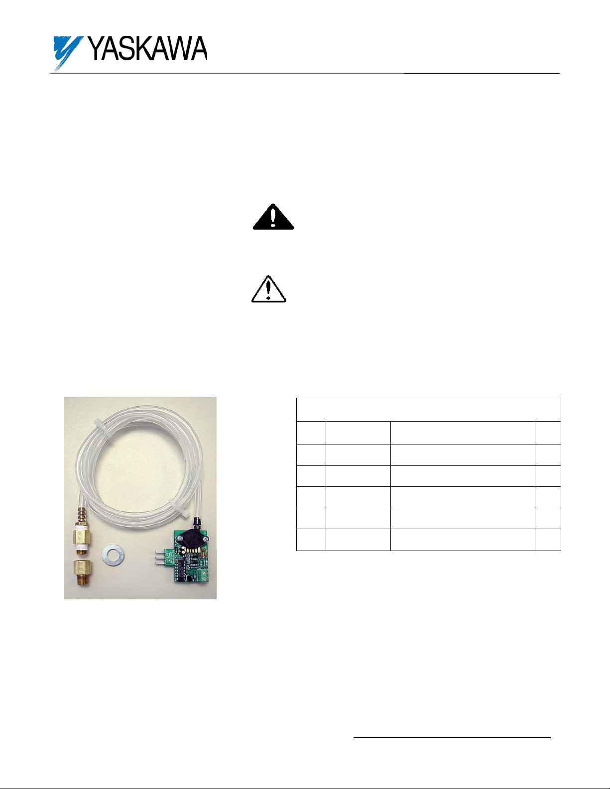
Figure 1. AI-010 Option Kit
5
Option Kit AI-010 Contents
Item
Part Number Description Qty
No
1 5P70-0247 Brass Female to Male Adapter 2
2 None 3/8 inch Flat Washer 1
3 5P70-0246 Brass Hose Barb to Male Adapter 1
4 5P70-0245 1/8 inch PVC (vinyl) tubing 5 Ft
5 UTC000038 Pressure Sensor Card 1
Yaskawa Electric America, Inc – www.drives.com
IG.AFD.50, Page 1 of 5
Date: 05/22/2007, Rev: 07-05
Page 2
3-15PSI Pressure Transducer Option Card
Pressure Transducer Installation on E7, F7, G7, P7 or GPD506/P5 Drives
1. Turn OFF all power to the drive.
2. Remove the drive’s front cover. Verify that “CHARGE” indicator lamp is off.
3. Verify voltage has been disconnected by using a voltmeter to check for voltage at incoming power terminals (L1, L2, L3).
4. Unpack and verify the contents of the option kit (See Figure 1).
5. Drill a 13/32-inch hole through the enclosure taking care not to damage any internal com ponents. The hole may be drilled
in any area that will not restrict or create crimps in the vinyl tubing when installed. Remove any burrs from the drilled hole.
6. Skip to step 7.
Pressure Transducer Installation on E7L Electronic Bypass Contro l
1. Turn OFF all power to the panel.
2. Remove drive front cover, if available. Verify that “CHARGE” indicator lamp is off.
3. Verify voltage has been disconnected by using a voltmeter to check for voltage at incoming power terminals (L1, L2, L3).
4. Replace and secure the drive front cover, if available.
5. Unpack and verify the contents of the option kit. See Figure 1.
6. Drill a 13/32-inch hole through the enclosure taking care not to damage any internal com ponents. The hole may be drilled
in any area that will not restrict or create crimps in the vinyl tubing when installed. Remove any burrs from the drilled hole.
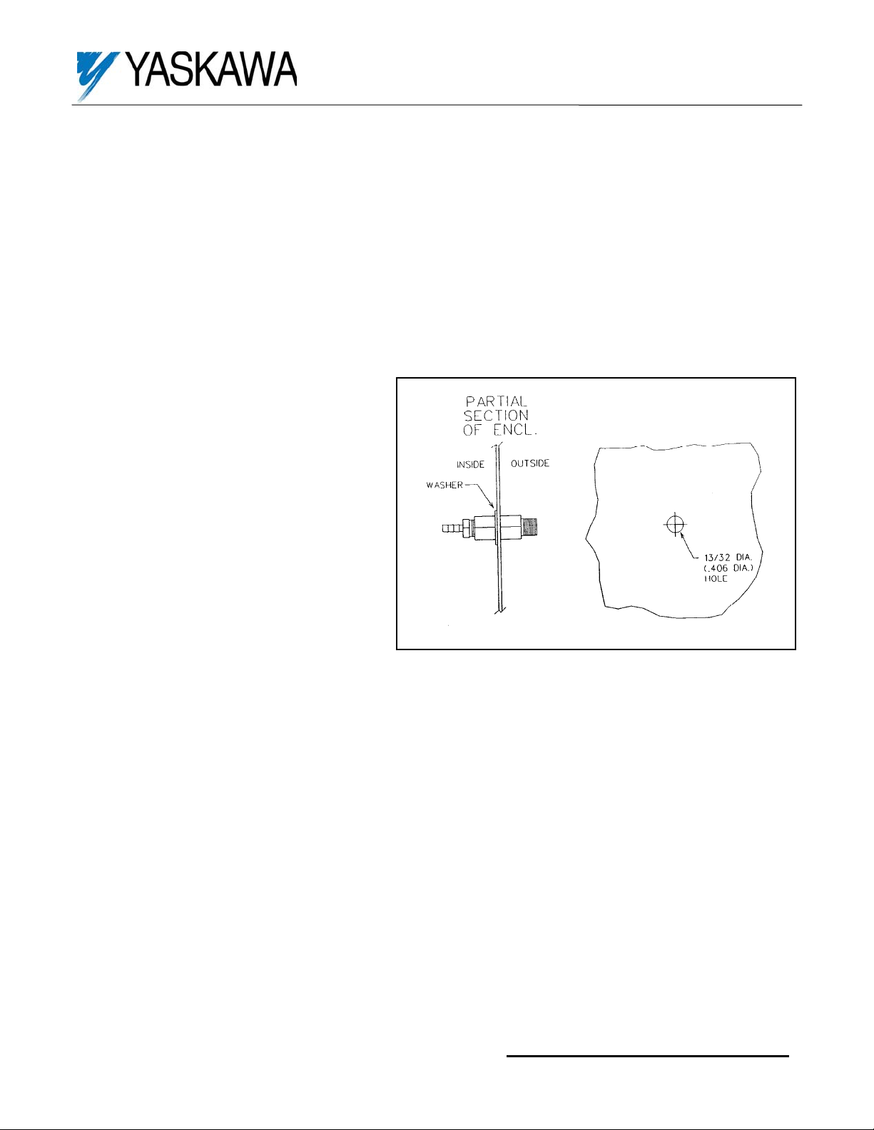
Refer to Figure 2 – Installing Adapters (All)
7. Thread the hose barb adapter into the inner
adapter and tighten securely. Then insert the
assembled hose barb and adapter, with flat
washer, through the drilled hole from inside the
Drive enclosure, thread the second adapter on
from the outside and tighten securely.
8. Press one end of the vinyl tubing onto the hose
barb of the transducer on the Pressure Sensor
Card.
Figure 2: Installing the Hose Adaptor
Refer to Figure 3 – Installing Pressure Sensor PCB on E7, F7, G7, P7 or GPD506/P5 Drive
9. Install the Pressure Sensor Card on the drive’s control board terminals as shown in Figur es 3 and 4. The fingers will fit
inside the terminal holes of the Drive, (Terminals FI, FS, and FC for GPD506/P5 drives or A2, +V and AC for E7/F7/G7/P7
drives). Please note that the card will be mounted with topside up, where the components are visible and not the
soldering. The (2) terminals “+V” and “AC” on the card are connected to the same (2) fingers on the card, and are
provided for customer thru connections (They are not used by the card).
10. Route the tubing the best way to the barb fitting, cut off any excess length and press onto the barb. If the tubing is already
pressed onto the barb, use a knife to place a sideways slit into the tubing, at the barb to remove it. Then cut the tubing to
desired length and press onto barb.
11. Connect the 3-15PSI pneumatic signal to the adapter on the outside of the drive enclosure.
12. Apply the maximum pressure (20PSI) to the hose to verify its proper installation and detect any leakage or breakage. After
this test, lower the pressure down to minimum (less than 2PSI) or zero.
13. Skip to step 14.
Refer to Figure 4 – Installing Pressure Sensor PCB on E7L Electronic Bypass
9. If option J or L (Lonworks) is installed, a wire-jumper should be placed between pins 2 and 7 of TB5. For this purpose, you
might need a short or right-angled screwdriver.
10. Again if option J or L is installed, set S4/2 to ON position, otherwise set it to OFF.
11. Install the Pressure Sensor Card on the Electronic Bypass Control inside the E7L Bypass panel, as sho wn in F igure 4.
The fingers will fit inside the terminal holes of the board’s TB5, Pins 7, 8 and 9. If the transducer card is to be installed on
the Electronic Bypass Control, in the field, a short or right-angled screwdriver will be necessary to tighten the three
terminal screws. Please note that the card will be mounted with topside up, where the components are visible and not the
Figure 2. Installing Adapters
-
Yaskawa Electric America, Inc – www.drives.com
IG.AFD.50, Page 2 of 5
Date: 05/22/2007, Rev: 07-05
Page 3

3-15PSI Pressure Transducer Option Card
A
p
(
A
A
-
soldering. The (2) terminals “+V” and “AC” on the card are connected to the same (2) fingers on the card, and are
provided for customer connections.
12. Route the tubing the best way to the barb fitting, cut off any excess length and press onto the barb. If the tubing is already
pressed onto the barb, use a knife to place a sideways slit into the tubing, at the barb to remove it. Then cut the tubing to
desired length and press onto barb.
13. Connect the 3-15PSI pneumatic signal to the adapter on the outside of the drive enclosure. Apply the maximum pressure
(20PSI) to the hose to verify its proper installation and detect any leakage or breakage. After this test, lower the pressure
down to minimum (less than 2PSI) or zero.
GPD 506/P5 AC Drive
Terminal No: FI
(With n043 =1) 4 - 20mA Auto
Mode FREQ. REF. In
ut
Terminal No: FS
+15VDC
Terminal No: FC
Analog Common
E7, F7 or P7 AC Drive
Terminal No: A2
4 - 20mA
uto Mode FREQ. REF. Input
Terminal No: +V
+15VDC
Terminal No: AC
Analog Common
G7 AC Drive
Terminal No: A2
4 - 20mA
uto Mode FREQ. REF. Input
Terminal No: +V
+15VDC
Terminal No:
Analog Common
C
Close up of Pressure Sensor Card
UTC000038)
Figure 3. Installation of Pressure Sensor Card onto Drive Control Board of
GPD506/P5, E7, F7, P7, and G7 Drives
Yaskawa Electric America, Inc – www.drives.com
IG.AFD.50, Page 3 of 5
Date: 05/22/2007, Rev: 07-05
Page 4

3-15PSI Pressure Transducer Option Card
E7L Electronic Bypass Control
-
Set-up for E7, F7, G7, P7 or GPD 506/P5 Drive
14. Now power up the drive. Do not run the motor at this time. The “ON” LED on the card should now be lit. If not, power
down the drive, check connections and then power up again.
15. Replace and secure the drive front cover.
16. Now monitor the frequency reference for the E7, F7, G7, P7 or GPD506/P5 drive through the keypad. The value sho uld
be zero. Now increase the pressure slowly to 15PSI, you should read between 59.9 and 60.0Hz. Adjustment of some
parameters may be required if the monitor values are not acceptable. Please note that due to the embedded high
accuracy of the card, adjusting the parameters any further for calibrating the card will require a very accurate pressure
gauge, otherwise the marginal values will only deteriorate.
17. Lower the pressure to 3PSI, the output frequency should read between 0.0 and 2.4Hz. In order to zero it at exactly 3 PSI
(or what your system can provide as 3PSI), change the setting of parameter “H3-11” for E7/F7/G7/P7, or “n051” for P5.
Now set the pressure to 15PSI. In order to have an output frequency of 60.0Hz, change the setting of parameter “H3-10”
for E7/F7/G7/P7, or “n050” for P5.
Figure 4. Installation of Pressure Sensor Card to E7L Electronic Bypass Control
Yaskawa Electric America, Inc – www.drives.com
IG.AFD.50, Page 4 of 5
Date: 05/22/2007, Rev: 07-05
Page 5

3-15PSI Pressure Transducer Option Card
18. The card and Drive are now set up and ready to go. For testing, you can set the pressure to 3PSI and run the drive. By
increasing the pressure, you should see that the motor accelerates and settles to a higher speed proportionally. T ypical
results are shown in the table 2 below.
Set-up for E7L Electronic Bypass Control
14. Now power up the panel and set it to OFF mode. The “ON” LED on the transducer card installed on the E7L control
should now be lit. If not, power down the panel, check connections and then power up again. Make sure that D1 LED
(DRV_OK) is lit on the E7L control card.
15. Close and secure the panel door.
16. If option J or L is installed, modify the drive parameters as: H1-02 Å 3.
17. Now monitor the frequency reference (U1-01) through the keypad on the panel door. By default it shows the output
frequency (U1-02). The value should be zero. Now increase the pressure slowly to 15PSI, you should read between 59.9
and 60.0Hz. Adjustment of some parameters may be required if the monitor values are not acceptable. Pleas e note that
due to the embedded high accuracy of the card, adjusting the parameters any further for calibrating the card will require a
very accurate pressure gauge, otherwise the marginal values will only deteriorate.
18. Lower the pressure to 3PSI, the output frequency should read 0.0Hz.
19. If adjustments are absolutely necessary to zero the frequency reference at higher pressure that your system provides as
3PSI, change the setting of parameter “H3-11”. And to get 60Hz at the PSI that your system can provide as maximum,
change the setting of parameter “H3-10”.
20. The transducer card, E7L Control card and drive are now set up and ready to go. For testing, you can set the pressure to
3PSI and press the “AUTO” on the bypass keypad to run the drive through the speed reference provided b y the
transducer card. By increasing the pressure, you should see that the motor accelerates and settles to a higher speed
proportionally. Typical results are shown in Table 2 above.
Specifications:
• Input Pressure: 3 - 14.5PSI (20.7 to 100kPa)
• Output Current: 4.0 - 20.0mADC ± 1%
• Bandwidth: 300Hz - 1kHz, depending on the loop impedance
• Power Supply: 15VDC ± 5%, 35mADC-max
• Open loop output: 11 - 12VDC
• Output with zero-pressure: 0VDC, 0mADC
• Linearity: 96.7% over full temperature range
• Accuracy: 95.7% over full temperature range
• Working Temperature Range: 0 - 70ºC
• Protection: Protected against short circuit, reverse supply/connection
• Input Interface: 4.78mm Hose Nipple
• Output Interface: 3 fingers, 0.1” pitch Header
• Dimensions: 1.86” X 1.88” X 0.33”
• Weight: Approx. 1oz. (35 grams)
Frequency
Reference
PSI Minimum 2.9 4.4 4.8 6.1 8.7 10.3 12.3 14.3
PSI Maximum 3.1 4.6 5.0 6.3 8.8 10.5 12.5 14.5
Table 2:The relationship between the applied pressure and frequency reference on the drive
0Hz 10Hz 12Hz 20Hz 30Hz 40Hz 50Hz 60Hz
-
Yaskawa Electric America, Inc – www.drives.com
IG.AFD.50, Page 5 of 5
Date: 05/22/2007, Rev: 07-05
 Loading...