

Page 1
MEMOCON GL120, GL130
120-SERIES I/O MODULES
USER'S MANUAL
MANUAL NO. SIE-C825-20.22C
Page 2
Manual Contents
This manual describes specifications, connections, and precautions for 120-series
I/O Modules. The 120-series I/O Modules are used with the MEMOCON GL120,
GL130 Programmable Controllers (PLCs).
Read this manual carefully and be sure to understand the information provided
before attempting to install or use 120-series I/O Modules.
Also, keep this manual in a safe place so that it can be used whenever necessary.
Visual Aids
The following aids are used to indicate certain types of information for easier refer-
ence.
Indicates references for additional information.
IMPORTANT
EXAMPLE
INFO
SUMMARY
Note
TERMS
Notice
WARNING
Indicates important information that should be memorized.
Indicates application examples.
Indicates supplemental information.
Indicates a summary of the important points of explanations.
Indicates inputs, operations, and other information required for correct operation
but that will not cause damage to the device.
Indicates definitions of terms used in the manual.
The following conventions are used to indicate precautions in this manual. Failure to
heed precautions provided in this manual can result in injury to people or damage to
the products.
Indicates precautions that, if not heeded, could possibly result in loss of life or seri-
ous injury.
CAUTION
Indicates precautions that, if not heeded, could result in relatively serious or minor
injury, damage to the product, or faulty operation.
© Yaskawa, 1998
All rights reserved. No part of this publication may be reproduced, stored in a retrieval system,
or transmitted, in any form, or by any means, mechanical, electronic, photocopying, recording,
or otherwise, without the prior written permission of Yaskawa. No patent liability is assumed
with respect to the use of the information contained herein. Moreover, because Yaskawa is constantly striving to improve its high-quality products, the information contained in this manual is
subject to change without notice. Every precaution has been taken in the preparation of this
manual. Nevertheless, Yaskawa assumes no responsibility for errors or omissions. Neither is
any liability assumed for damages resulting from the use of the information contained in this
publication.
iii
Page 3

CONTENTS
Manual Contents - - - - - - - - - - - - - - - - - - - - - - - - - - - - - - - - - - - - - - - iii
Visual Aids- - - - - - - - - - - - - - - - - - - - - - - - - - - - - - - - - - - - - - - - - - - - iii
Notice - - - - - - - - - - - - - - - - - - - - - - - - - - - - - - - - - - - - - - - - - - - - - - - iii
1 Introduction and Precautions
1.1 Overview of Manual - - - - - - - - - - - - - - - - - - - - - - - - - - - - - 1-2
1.2 Precautions - - - - - - - - - - - - - - - - - - - - - - - - - - - - - - - - - - - 1-3
1.2.1 Safety Precautions - - - - - - - - - - - - - - - - - - - - - - - - - - - - - - - - - - - - -1-3
1.2.2 Installation Precautions - - - - - - - - - - - - - - - - - - - - - - - - - - - - - - - - - -1-4
1.2.3 Removal Precautions - - - - - - - - - - - - - - - - - - - - - - - - - - - - - - - - - - -1-5
1.2.4 Wiring Precautions - - - - - - - - - - - - - - - - - - - - - - - - - - - - - - - - - - - - -1-6
1.2.5 Application Precautions- - - - - - - - - - - - - - - - - - - - - - - - - - - - - - - - - 1-11
1.2.6 Maintenance - - - - - - - - - - - - - - - - - - - - - - - - - - - - - - - - - - - - - - - - 1-14
1.3 Using This Manual - - - - - - - - - - - - - - - - - - - - - - - - - - - - - 1-15
2 Models and General Specifications of I/O Modules
2.1 General Specifications - - - - - - - - - - - - - - - - - - - - - - - - - - - 2-2
2.2 I/O Modules - - - - - - - - - - - - - - - - - - - - - - - - - - - - - - - - - - - 2-3
2.2.1 Models of I/O Modules - - - - - - - - - - - - - - - - - - - - - - - - - - - - - - - - - -2-3
2.2.2 Overview of I/O Module Specifications - - - - - - - - - - - - - - - - - - - - - - -2-5
2.2.3 Using I/O Modules - - - - - - - - - - - - - - - - - - - - - - - - - - - - - - - - - - - -2-10
3 Digital I/O Specifications
3.1 Digital Input Module specifications - - - - - - - - - - - - - - - - - - 3-2
3.1.1 100-VAC 16-point Input Module - - - - - - - - - - - - - - - - - - - - - - - - - - - -3-2
3.1.2 200-VAC 16-point Input Module - - - - - - - - - - - - - - - - - - - - - - - - - - - -3-6
3.1.3 12/24-VDC 16-point Input Module - - - - - - - - - - - - - - - - - - - - - - - - - 3-10
3.1.4 12/24-VDC 32-point Input Module - - - - - - - - - - - - - - - - - - - - - - - - - 3-14
3.1.5 12/24-VDC 64-point Input Module - - - - - - - - - - - - - - - - - - - - - - - - - 3-18
3.2 Digital Output Module Specifications - - - - - - - - - - - - - - - - 3-24
3.2.1 100/200-VAC 8-point Output Module - - - - - - - - - - - - - - - - - - - - - - -3-24
3.2.2 100/200-VAC 16-point Output Module - - - - - - - - - - - - - - - - - - - - - -3-28
3.2.3 12/24-VDC 8-point Output Module - - - - - - - - - - - - - - - - - - - - - - - - -3-32
3.2.4 12/24-VDC 16-point Output Module (Sinking) - - - - - - - - - - - - - - - - - 3-36
3.2.5 12/24-VDC 16-point Output Module (Sourcing) - - - - - - - - - - - - - - - -3-40
3.2.6 12/24-VDC 32-point Output Module - - - - - - - - - - - - - - - - - - - - - - - -3-44
3.2.7 12/24-VDC 64-point Output Module - - - - - - - - - - - - - - - - - - - - - - - -3-49
3.2.8 Relay Contact 16-point Output Module - - - - - - - - - - - - - - - - - - - - - -3-55
3.3 I/O Module Cables - - - - - - - - - - - - - - - - - - - - - - - - - - - - - 3-60
3.3.1 I/O Module Cable Types - - - - - - - - - - - - - - - - - - - - - - - - - - - - - - - -3-60
3.3.2 W0300 Cables (Model No. JZMSZ-120W0300-) - - - - - - - - - - - -3-62
3.3.3 W0302 Cables (Model No. JZMSZ-120W0302-) - - - - - - - - - - - -3-65
3.3.4 W0301 Cables (Model No. JZMSZ-120W0301-) - - - - - - - - - - - -3-68
3.3.5 32-point I/O Connector Terminal Block - - - - - - - - - - - - - - - - - - - - - -3-71
3.3.6 W5410 Cables (Model No. JEPMC-W5410-) - - - - - - - - - - - - - - - 3-74
v
Page 4

3.4 I/O Allocation - - - - - - - - - - - - - - - - - - - - - - - - - - - - - - - - - 3-81
3.4.1 16-point Input Modules - - - - - - - - - - - - - - - - - - - - - - - - - - - - - - - - - 3-81
3.4.2 32-point Input Modules - - - - - - - - - - - - - - - - - - - - - - - - - - - - - - - - - 3-84
3.4.3 64-point Input Modules - - - - - - - - - - - - - - - - - - - - - - - - - - - - - - - - - 3-87
3.4.4 8-point Output Modules - - - - - - - - - - - - - - - - - - - - - - - - - - - - - - - - 3-92
3.4.5 16-point Output Modules - - - - - - - - - - - - - - - - - - - - - - - - - - - - - - - 3-94
3.4.6 32-point Output Modules - - - - - - - - - - - - - - - - - - - - - - - - - - - - - - - 3-97
3.4.7 64-point Output Modules - - - - - - - - - - - - - - - - - - - - - - - - - - - - - - 3-101
3.5 Operations Using MEMOSOFT - - - - - - - - - - - - - - - - - - - 3-106
3.5.1 MEMOSOFT Versions Supporting 64-point I/O Modules - - - - - - - - 3-106
3.5.2 Digital Input Module I/O Allocation Screen - - - - - - - - - - - - - - - - - - 3-107
3.5.3 Digital Output Module I/O Allocation Screen - - - - - - - - - - - - - - - - - 3-108
3.5.4 I/O Allocations - - - - - - - - - - - - - - - - - - - - - - - - - - - - - - - - - - - - - - 3-109
4 Analog I/O Specifications
4.1 Analog Input Specifications - - - - - - - - - - - - - - - - - - - - - - - - 4-2
4.1.1 Analog Input Modules (±10 V, 4 channels) - - - - - - - - - - - - - - - - - - - - 4-2
4.1.2 Analog Input Modules (0 to 10 V, 4 channels) - - - - - - - - - - - - - - - - - - 4-8
4.1.3 Analog Input Modules (4 to 20-mA, 4 channels) - - - - - - - - - - - - - - - 4-14
4.2 Analog Output Specifications- - - - - - - - - - - - - - - - - - - - - - 4-20
4.2.1 Analog Output Modules (±10 V, 2 channels) - - - - - - - - - - - - - - - - - - 4-20
4.2.2 Analog Output Modules (0 to 10 V, 2 channels) (0 to 5 V, 2 channels)4-25
4.2.3 Analog Output Modules (4 to 20-mA, 2 channels) - - - - - - - - - - - - - - 4-30
4.3 I/O Allocation - - - - - - - - - - - - - - - - - - - - - - - - - - - - - - - - - 4-35
4.3.1 Analog Input Modules- - - - - - - - - - - - - - - - - - - - - - - - - - - - - - - - - - 4-35
4.3.2 Analog Output Modules - - - - - - - - - - - - - - - - - - - - - - - - - - - - - - - - 4-39
4.4 Operations Using MEMOSOFT - - - - - - - - - - - - - - - - - - - - 4-41
4.4.1 Analog Input Module I/O Allocation Screen- - - - - - - - - - - - - - - - - - - 4-41
4.4.2 Analog Output Module I/O Allocation Screen - - - - - - - - - - - - - - - - - 4-42
4.4.3 I/O Allocations - - - - - - - - - - - - - - - - - - - - - - - - - - - - - - - - - - - - - - - 4-43
5 Register I/O Specifications
5.1 Register Input Specifications - - - - - - - - - - - - - - - - - - - - - - - 5-2
5.1.1 Register Input Modules- - - - - - - - - - - - - - - - - - - - - - - - - - - - - - - - - - 5-2
5.2 Register Output Specifications- - - - - - - - - - - - - - - - - - - - - - 5-6
5.2.1 Register Output Modules - - - - - - - - - - - - - - - - - - - - - - - - - - - - - - - - 5-6
5.3 I/O Allocation - - - - - - - - - - - - - - - - - - - - - - - - - - - - - - - - 5-10
5.3.1 Register Input Modules- - - - - - - - - - - - - - - - - - - - - - - - - - - - - - - - - 5-10
5.3.2 Register Output Modules - - - - - - - - - - - - - - - - - - - - - - - - - - - - - - - 5-13
5.4 Operations Using MEMOSOFT - - - - - - - - - - - - - - - - - - - - 5-17
5.4.1 Register Input Module I/O Allocation Screen- - - - - - - - - - - - - - - - - - 5-17
5.4.2 Register Output Module I/O Allocation Screen - - - - - - - - - - - - - - - - 5-18
5.4.3 I/O Allocations - - - - - - - - - - - - - - - - - - - - - - - - - - - - - - - - - - - - - - - 5-20
vi
Page 5

6 Installation and Wiring
6.1 Installing Modules - - - - - - - - - - - - - - - - - - - - - - - - - - - - - - 6-2
6.1.1 Module Installation Location - - - - - - - - - - - - - - - - - - - - - - - - - - - - - -6-2
6.1.2 Installing I/O Modules with Terminal Blocks - - - - - - - - - - - - - - - - - - - -6-4
6.1.3 Installing I/O Modules with Connectors - - - - - - - - - - - - - - - - - - - - - -6-10
6.2 Panel Wiring - - - - - - - - - - - - - - - - - - - - - - - - - - - - - - - - - 6-13
6.2.1 Separation of Power Supply Systems- - - - - - - - - - - - - - - - - - - - - - -6-13
6.2.2 Wiring AC I/O Modules - - - - - - - - - - - - - - - - - - - - - - - - - - - - - - - - - 6-14
6.2.3 Wiring DC I/O Modules - - - - - - - - - - - - - - - - - - - - - - - - - - - - - - - - -6-17
6.2.4 Wiring Analog I/O Modules - - - - - - - - - - - - - - - - - - - - - - - - - - - - - -6-25
6.2.5 Grounding - - - - - - - - - - - - - - - - - - - - - - - - - - - - - - - - - - - - - - - - - - 6-28
6.3 External Wiring - - - - - - - - - - - - - - - - - - - - - - - - - - - - - - - 6-31
6.3.1 External Wiring for Digital I/O Modules - - - - - - - - - - - - - - - - - - - - - -6-31
6.4 Precautions on Wiring - - - - - - - - - - - - - - - - - - - - - - - - - - 6-32
6.4.1 AC Input Modules - - - - - - - - - - - - - - - - - - - - - - - - - - - - - - - - - - - - 6-32
6.4.2 AC Output Modules - - - - - - - - - - - - - - - - - - - - - - - - - - - - - - - - - - - 6-35
6.4.3 DC Input Modules- - - - - - - - - - - - - - - - - - - - - - - - - - - - - - - - - - - - - 6-40
6.4.4 DC Output Modules - - - - - - - - - - - - - - - - - - - - - - - - - - - - - - - - - - -6-45
6.4.5 Connections between AC I/O Modules - - - - - - - - - - - - - - - - - - - - -6-49
6.4.6 Connections between DC I/O Modules - - - - - - - - - - - - - - - - - - - - -6-50
6.4.7 Analog Input Modules - - - - - - - - - - - - - - - - - - - - - - - - - - - - - - - - - -6-50
6.4.8 Analog Output Modules- - - - - - - - - - - - - - - - - - - - - - - - - - - - - - - - - 6-51
6.4.9 External Power Supplies - - - - - - - - - - - - - - - - - - - - - - - - - - - - - - -6-52
7 Maintenance
7.1 Built-in Fuses - - - - - - - - - - - - - - - - - - - - - - - - - - - - - - - - - 7-2
7.1.1 I/O Modules with Built-in Fuses - - - - - - - - - - - - - - - - - - - - - - - - - - - -7-2
7.1.2 Built-in Fuses - - - - - - - - - - - - - - - - - - - - - - - - - - - - - - - - - - - - - - - - -7-3
7.1.3 Replacement of Built-in Fuses - - - - - - - - - - - - - - - - - - - - - - - - - - - - -7-5
7.2 Hot Swapping - - - - - - - - - - - - - - - - - - - - - - - - - - - - - - - - - 7-6
7.2.1 Hot Swapping- - - - - - - - - - - - - - - - - - - - - - - - - - - - - - - - - - - - - - - - -7-6
8 EN Standard Low voltage Directive Compliant I/O Modules
8.1 EN Standard Compliant I/O Modules - - - - - - - - - - - - - - - - - 8-2
8.1.1 Low Voltage Directive Compliant I/O Modules - - - - - - - - - - - - - - - - - -8-2
8.1.2 External Appearances- - - - - - - - - - - - - - - - - - - - - - - - - - - - - - - - - - -8-3
8.1.3 EN Standards - - - - - - - - - - - - - - - - - - - - - - - - - - - - - - - - - - - - - - - - -8-5
8.1.4 Specifications of the I/O Mo
dules - - - - - - - - - - - - - - - - - - - - - - - - - - -8-7
Appendix A External Dimensions
A.1 I/O Module Types- - - - - - - - - - - - - - - - - - - - - - - - - - - - - - - A-2
A.2 I/O Modules with Terminal Blocks - - - - - - - - - - - - - - - - - - - A-3
A.3 DC 32-point I/O Modules - - - - - - - - - - - - - - - - - - - - - - - - - A-3
A.4 DC 64-point I/O Modules - - - - - - - - - - - - - - - - - - - - - - - - - A-4
A.5 Register I/O Modules - - - - - - - - - - - - - - - - - - - - - - - - - - - - A-4
INDEX
vii
Page 6

Introduction and Precautions
This chapter introduces the features of 120-series I/O Modules and pro-
vides precautions for the use of this manual and the product.
Read this chapter before attempting to read the rest of the manual or use
the product.
1.1 Overview of Manual - - - - - - - - - - - - - - - - - - - - - - - - - - - - - 1-2
1.2 Precautions - - - - - - - - - - - - - - - - - - - - - - - - - - - - - - - - - - -1-3
1.2.1 Safety Precautions - - - - - - - - - - - - - - - - - - - - - - - - - - - - - - - - - - - - 1-3
1.2.2 Installation Precautions - - - - - - - - - - - - - - - - - - - - - - - - - - - - - - - - - 1-4
1.2.3 Removal Precautions - - - - - - - - - - - - - - - - - - - - - - - - - - - - - - - - - - 1-5
1.2.4 Wiring Precautions - - - - - - - - - - - - - - - - - - - - - - - - - - - - - - - - - - - - 1-6
1.2.5 Application Precautions - - - - - - - - - - - - - - - - - - - - - - - - - - - - - - - - 1-11
1.2.6 Maintenance - - - - - - - - - - - - - - - - - - - - - - - - - - - - - - - - - - - - - - - 1-14
1
1
1.3 Using This Manual - - - - - - - - - - - - - - - - - - - - - - - - - - - - - 1-15
1-1
Page 7

1 Introduction and Precautions
1.1 Overview of Manual
• This manual describes the functional specifications of the 120-series I/O Modules used for the MEMOCON GL120 and GL130 Programmable Controllers.
Read this manual carefully in order to use the 120-series I/O Modules properly.
Also, keep this manual in a safe place so that it can be used whenever necessary.
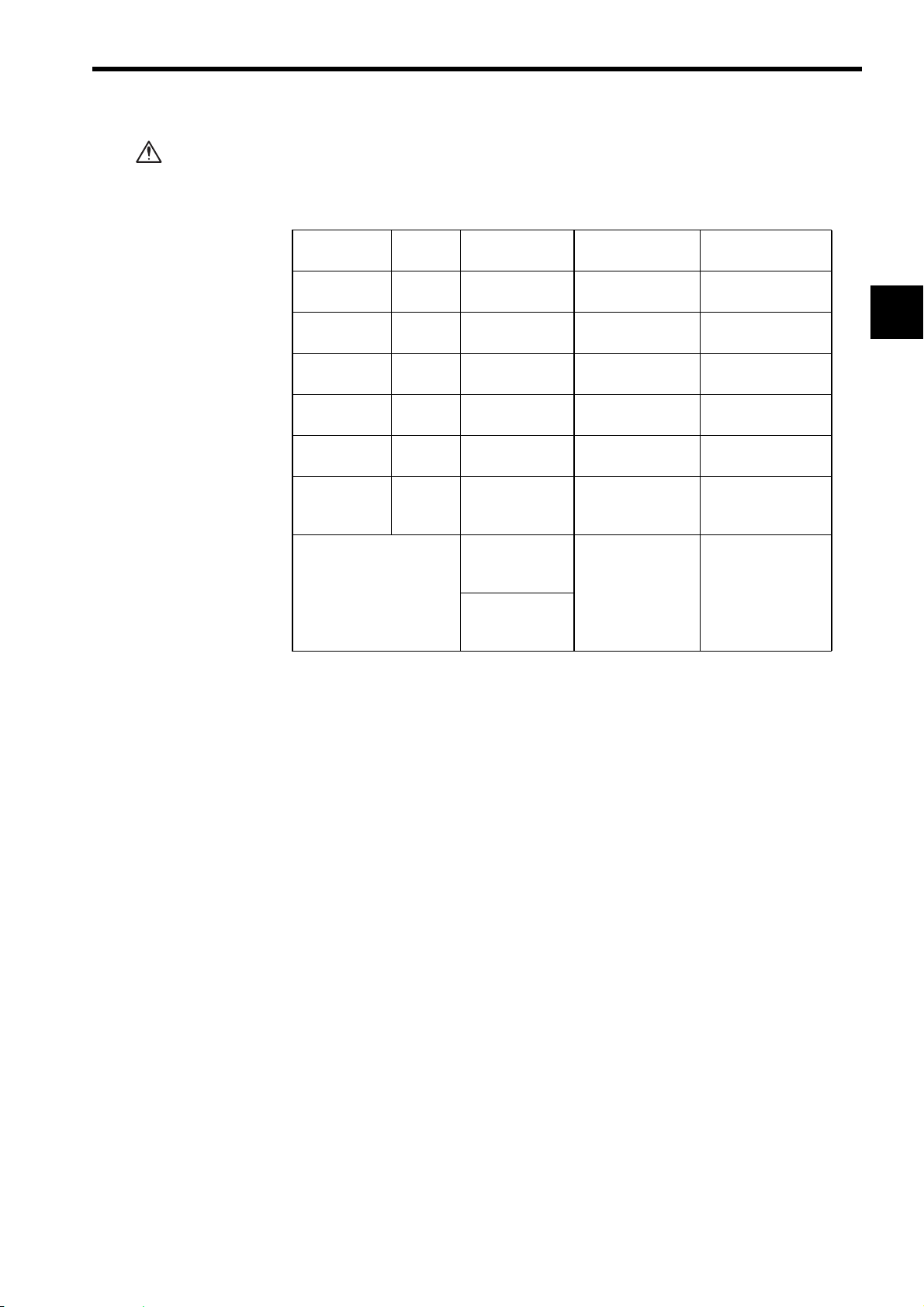
• Refer to the following manuals for related Peripheral Devices and Modules.
Product Manual Name Manual No. Contents
CPU Module MEMOCON GL120, GL130
Hardware User’s Manual
MEMOCON GL120, GL130
Software User’s Manual Vol. 1
MEMOCON GL120, GL130
Software User’s Manual Vol.2
HumanMachine
Interface
MEMOCON GL120, GL130
MEMOSOFT for P120
Programming Panel
User’s Manual
MEMOCON GL120, GL130
MEMOSOFT
User’s Manual
MEMOCON GL120, GL130
MEMOSOFT for Windows
User’s Manual
SIEZ-C825-20.1 Gives information on the GL120 and GL130 hard-
ware, including explanations on the following items.
1) System configuration
2) System components
3) Function and specifications of system components
4) Installation and wiring
5) Examples of panel-layout and hole dimensions
6) External Dimensions
SIEZ-C825-20.11 Describes the following items for the GL120 and
GL130.
1) Operating principles
2) I/O allocation
3) Overview of instructions
4) Instruction processing times
SIEZ-C825-20.12 Describes the programming instructions used to
create ladder programs for the GL120 and GL130.
The following items are explained in other manuals.
1) Expansion Math instructions
2) Process control instructions
3) Communications instructions
4) Motions control instructions (ladder motion
instructions)
5) Motion language
SIEZ-C825-60.7 Describes the functions, specifications, and opera-
tional methods of the Programming Panel P120 with
built-in MEMOSOFT.
SIEZ-C825-60.10 Describes the functions and operational methods of
MEMOSOFT for DOS.
SIEZ-C825-60.25 Describes the functions and operational methods of
MEMOSOFT for Windows.
• Thoroughly check the specifications and conditions or restrictions of the product
before use.
1-2
Page 8

1.2 Precautions
This section outlines general precautions that apply to using this manual and the
product. Read this section first before reading the remainder of the manual.
1.2.1 Safety Precautions - - - - - - - - - - - - - - - - - - - - - - - - - - - - - - - - - - - - 1-3
1.2.2 Installation Precautions - - - - - - - - - - - - - - - - - - - - - - - - - - - - - - - - - 1-4
1.2.3 Removal Precautions - - - - - - - - - - - - - - - - - - - - - - - - - - - - - - - - - - 1-5
1.2.4 Wiring Precautions - - - - - - - - - - - - - - - - - - - - - - - - - - - - - - - - - - - - 1-6
1.2.5 Application Precautions - - - - - - - - - - - - - - - - - - - - - - - - - - - - - - - - 1-11
1.2.6 Maintenance - - - - - - - - - - - - - - - - - - - - - - - - - - - - - - - - - - - - - - - 1-14
1.2.1 Safety Precautions
• The GL120 and GL130 were not designed or manufactured for use in devices or
systems directly related to human life. Users who intend to use the product
described in this manual for special purposes such as devices or systems relating to transportation, medical, space aviation, atomic power control, or underwater use must contact Yaskawa Electric Corporation beforehand.
1.2 Precautions
1
• This product has been manufactured under strict quality control guidelines. However, if this product is to be installed in any location in which a failure of GL120
and GL130 involves a life and death situation or in a facility where failure may
cause a serious accident, safety devices MUST be installed to minimize the likelihood of any accident.
• Any illustrations, photographs, or examples used in this manual are provided as
examples only and may not apply to all products to which this manual is applicable.
• The products and specifications described in this manual or the content and presentation of the manual may be changed without notice to improve the product
and/or the manual. A new version of the manual will be released under a revised
manual number when any changes are made.
• Contact your Yaskawa representative or a Yaskawa office listed on the back of
this manual to order a new manual whenever this manual is damaged or lost.
Please provide the manual number listed on the front cover or this manual when
ordering.
• Contact your Yaskawa representative or a Yaskawa office listed on the back of
this manual to order new nameplates whenever a nameplate becomes worn or
damaged.
• Yaskawa cannot guarantee the quality of any products that have been modified.
Yaskawa assumes no responsibility for any injury or damage caused by a modified product.
1-3
Page 9

1 Introduction and Precautions
1.2.2 Installation Precautions
1.2.2 Installation Precautions
Abide by the following precautions when installing MEMOCON systems.
CAUTION
CAUTION
CAUTION
• The installation environment must meet the environmental conditions given in product catalogs and manuals. Using the GL120 and GL130 in environments subject to
high temperatures, high humidity, excessive dust, corrosive gases, vibration, or
shock can lead to electrical shock, fire, or faulty operation. Do not use the GL120
and GL130 in the following locations.
• Locations subject to direct sunlight or ambient temperatures not between 0 °C
and 60 °C.
• Locations subject to relative humidity in excess of 95%, or condensation
because of rapid changes in humidity.
• Locations subject to corrosive or flammable gas.
• Locations that would subject the GL120 and GL130 to direct vibration or
shock.
• Locations subject to contact with water, oil, chemicals, and so on.
• Install Modules as described in the user’s manuals.
Faulty or inappropriate installation may result in detachment or malfunction.
• Do not remove the connector covers from the Module connectors on the Mounting
Base slots where no Modules are installed.
The presence of any foreign matter in a Module connector may cause the
GL120 and GL130 to malfunction.
CAUTION
CAUTION
CAUTION
CAUTION
CAUTION
• Make sure that all mounting screws for the Modules are securely tightened.
Loose screws may cause malfunction of the GL120 and GL130.
• Make sure that all mounting screws for the terminal block are securely tightened.
Loose screws may cause a malfunction of the GL120 and GL130.
• When installing the terminal block for the AC I/O Modules, turn OFF the AC power
supply to the I/O Modules for inputting signals and for driving load.
Installing a terminal block with the AC power being supplied to the terminal of
the external power supply for the AC I/O Modules may cause an electric shock if
the power supply terminals are touched.
• When using a single-phase AC power supply (100/200 VAC) for driving loads of the
Relay Contact Output Module, turn OFF the AC power to the Modules for driving
loads before installing the terminal block for the Modules.
Installing a terminal block with the AC power being supplied to the external
power supply terminal of the Relay Contact Output Module may cause an electric shock if the power supply terminals are touched.
• Make sure that all cable connectors for the Module are securely inserted and tightened.
Incorrect connections may cause malfunction of the GL120 or GL130.
1-4
Page 10

1.2.3 Removal Precautions
1.2 Precautions
CAUTION
CAUTION
CAUTION
CAUTION
• Always turn OFF the AC power supply to the AC I/O Modules that are used for
inputting signals and driving loads before removing the terminal block from the AC I/
O Modules.
Removing a terminal block with AC power to the external power supply terminal
of the AC I/O Modules may cause an electric shock at touching the power supply terminals.
1
• When using a single-phase AC power supply (100/200 VAC) for driving loads of the
Relay Contact Output Module, turn OFF the AC power to the Modules for driving
loads before removing the terminal block for the Modules.
Removing a terminal block with the AC power being supplied to the external
power supply terminal of the Relay Contact Output Module may cause an electric shock if the power supply terminals are touched.
• When inserting or removing an AC I/O Module while the AC power supply is turned
ON, install a safety switch for each Module and always turn this safety switch OFF
to turn OFF the AC power supply to the Module.
Inserting or removing an AC I/O Module while AC power is being supplied may
result in an electric shock at touching the power supply terminals.
• When using a single-phase AC power supply (100/200 VAC) for driving the loads of
the Relay Contact Output Module, install a safety switch for each Module. Before
inserting or removing the Relay Contact Output Module, always turn this safety
switch OFF to turn OFF the AC power supply to the Module.
Inserting or removing a Relay Contact Output Module while AC power is being
supplied may result in an electric shock at touching the power supply terminals.
1-5
Page 11

1 Introduction and Precautions
1.2.4 Wiring Precautions
1.2.4 Wiring Precautions
CAUTION
CAUTION
CAUTION
CAUTION
CAUTION
• Wiring must be performed by qualified personnel.
Wrong or inappropriate wiring may result in fire, product failure, or electric
shock.
• Connect the correct power supply for the required ratings.
Connecting unsuitable power supplies may result in fires.
• Do not allow foreign matter such as cable chips in the Modules or Mounting Bases.
Foreign matter in the Modules or Mounting Bases may cause fire, failures and/
or malfunctions.
• Connect power supplies of the same phases to the common 1 and common 2 of the
AC I/O Module.
If power supplies of different phases are connected, overheating or fire may
occur.
• If using a single-phase AC power supply (100/200 VAC) for driving the loads of the
Relay Contact Output Module, connect power supplies with the same phases to the
common 1 and common 2 of the Module.
CAUTION
CAUTION
If power supplies of different phases are connected, overheating or fire may
occur.
• If using an Output Module, connect a fuse that complies with the load specifications
in series with the load.
A protective fuse is not built into the following Output Modules. If a fuse is not
connected, a fire or damage to the device or output circuits may occur if the load
is short-circuited or the circuit overloaded.
• 100/200-VAC 8-point Output Module: Model No. JAMSC-120DAO083000
• Relay contact 16-point Output Module: Model No. JAMSC-120DRA84300
• If using an Output Module, connect a fuse that complies with the load specifications
in series with the load.
A protective fuse built into the following Output Modules does not protect the
output element. If a fuse is not connected, a fire or damage to the device or output circuits may occur if the load is short-circuited or the circuit overloaded.
• 100/200-VAC 16-point Output Module: Model No. JAMSC-120DAO84300
• 12/24-VDC 8-point Output Module: Model No. JAMSC-120DDO33000
• 12/24-VDC 16-point Output Module: Model No. JAMSC-120DAO34310
• 12/24-VDC 16-point Output Module: Model No. JAMSC-120DAO34320
• 12/24-VDC 32-point Output Module: Model No. JAMSC-120DAO35410
• 12/24-VDC 64-point Output Module: Model No. JAMSC-120DAO36410
1-6
Page 12

1.2 Precautions
CAUTION
CAUTION
CAUTION
CAUTION
• Connect an AC power supply (100/200 VAC) or a DC power supply (12/24 VDC) to
the Power Supply for driving loads of the Relay Contact Output Module.
Do not connect both an AC power supply and a DC power supply to one Module
at the same time. If unsuitable power supplies are connected, in overheating or
fire may result.
• Although a 0.6-A load can be connected to each output point for the AC 16-point
Output Module, the total load must be 2.4A or less for each common. Keep the
maximum load at 2.4A for each common.
If this limit is exceeded, damage may occur to the output circuit.
• Although a 0.5-A load can be connected to each output point for the DC 16-point
Output Module, the total load must be 1.0 A or less for each of the four output
points. Keep the load distribution within the 1.0 A limit.
If this limit is exceeded, damage may occur to the output circuit.
• Although a 0.3-A load can be connected to each output point of the DC 32-point
Output Module, the total load must be 0.4 A or less for each of the four output
points. Keep the load distribution within the 0.4 A limit.
If this limit is exceeded, damage may occur to the output circuit.
1
CAUTION
CAUTION
• If using an Output Module, connect a fuse that complies with the load specifications
in series with the load.
• 100/200-VAC 8-point Output Module: Model No. JAMSC-120DAO83000
• 100/200-VAC 16-point Output Module: Model No. JAMSC-120DAO84300
• 12/24-VDC 16-point Output Module (sinking output):
Model No. JAMSC-120DDO33000
• 12/24-VDC 16-point Output Module (sourcing output):
Model No. JAMSC-120DAO34320
• 12/24-VDC 32-point Output Module (sinking output):
Model No. JAMSC-120DAO35410
• 12/24 VDC 64-point Output Module (sinking output):
Model No. JAMSC-120DAO36410
• Relay Contact 16-point Output Module: Model No. JAMSC-120DAO84300
If a fuse is not connected, a fire or damage to the device or output circuit may
occur if the load is short-circuited or the circuit overloaded.
• If connecting an inductive load in parallel with AC Input Module, connect the surge
absorber in parallel with the inductive load to prevent surge voltage.
CAUTION
Failure to connect a surge absorber may result in damage to the AC Input Module.
• If connecting an inductive load to the AC Output Module, connect the surge
absorber in parallel with the inductive load to prevent surge voltage.
Failure to connect a surge absorber may result in damage to the AC Output
Module.
1-7
Page 13

1 Introduction and Precautions
1.2.4 Wiring Precautions
CAUTION
CAUTION
CAUTION
CAUTION
• If connecting an inductive load in parallel with DC Input Module, connect the flywheel diode in parallel with the inductive load to prevent surge voltage.
Failure to connect a flywheel diode may result in damage to the DC Input Module.
• If connecting an inductive load to the DC Output Module, connect the flywheel
diode in parallel with the inductive load to prevent surge voltage.
Failure to connect a flywheel diode may result in damage to the DC Output
Module.
• If connecting a contact to an inductive load of the DC Output Module, connect the
flywheel diode in parallel with the inductive load to prevent surge voltage.
Failure to connect a flywheel diode may result in damage to the DC Output
Module.
• Insulation is not provided between the channels of the Analog Input Module.
To insulate all the analog signals connected to the Analog Input Module, use a commercial isolation amplifier for each channel.
Incorrect connections may cause damages and malfunctions of the Analog
Input Modules.
CAUTION
CAUTION
CAUTION
CAUTION
• The maximum allowable load current for Analog Output Modules (±10V, 2 chan-
nels) is ±5 mA (2 kΩ). The load resistance must be 2 kΩ or more.
Incorrect connection may cause the output signal to be overloaded, and result in
damages or malfunction of the Analog Output Module.
• The maximum allowable load current for Analog Output Modules (0 to10V, 2 channels) is 5 mA (2 kΩ). The load resistance must be 2 kΩ or more.
Incorrect connection may cause the output signal to be overloaded, and result in
damages or malfunction of the Analog Output Module.
• The maximum allowable load current for Analog Output Modules (0 to 5V, 2 channels) is 2.5 mA (2 kΩ). The load resistance must be 2 kΩ or more.
Incorrect connection may cause the output signal to be overloaded, and result in
damages or malfunction of the Analog Output Module.
• The maximum allowable load resistance for Analog Output Modules (4 mA to 20
mA, 2 channels) is 550 kΩ). The load resistance must be 550 kΩ or more.
Incorrect connection may cause the output signal to be overloaded, and result in
damages or malfunction of the Analog Output Module.
CAUTION
• If using Low Voltage Directive compliant products, always use round crimp terminals for M3 screws and mount insulation cover at each crimp when connecting
wires to wiring terminals.
If bare wires are used, an electric shock or a short-circuit may result if the wires
become loose.
1-8
Page 14

1.2 Precautions
CAUTION
CAUTION
• Ground the shield of the shielded twisted-pair wire that connects to the Analog I/O
Module to one point (a resistance of 100 Ω max.).
Not grounding the shield of the shielded twisted-pair wire may result in malfunction of the GL120 and GL130.
• Ground the ground terminal of the Analog Input Module to a resistance of 100 Ω
max.
Not grounding the ground terminal may result in malfunction of the GL120 and
GL130.
Power Supply Noise Reduction
• Prevent noise from penetrating into the product by installing an isolation transformer or a noise filter for the external power supply.
Noise from power supply may result in malfunction of the GL120 and GL130.
• Do not install the GL120 and GL130 system components in the same control
panel as high-voltage or high-current circuits.
Here, high-voltage circuits are those with voltages of 600 VAC or 750 VDC
min. and high-current circuits are those with amperages of 800 A min.
1
• When installing the GL120 and GL130 system components in the same control
panel as low-voltage main circuits, separate the low-voltage circuits and related
devices as far as possible from the GL120 and GL130 system components and
wiring.
The recommended separation is 200 mm min. Here. low-voltage main circuits
are those with voltages up to 600 VAC or 750 VDC and amperages of 20 A
min.
• Do not bundle GL120 and GL130 wiring together with wiring for normal control
circuits.
Here, normal control circuits are those with voltages up to 600 VAC or 750
VDC and amperages up to 20 A.
Insert the Interface Cables Properly
• Insert the connectors of the various interface cables that are to be connected to
the GL120 and GL130 into the communication ports and secure them properly.
Improper insertion of interface cables may cause operational errors in the
GL120 and GL130.
1-9
Page 15

1 Introduction and Precautions
1.2.4 Wiring Precautions
Select, Separate, and Lay External Wiring Correctly
• I/O lines connecting external devices to the 120-series I/O Modules must be
selected based on the following considerations: mechanical strength, resistance
to noise, wiring distance, signal voltage, and so on.
• I/O lines must be separated from power lines both inside and outside the control
panel to minimize the affects of noise. Faulty operation may result if I/O lines are
not sufficiently separated from power lines.
Example of external wiring separation
Power lines General control
circuit cables
Steel-plate separator
Digital I/O
signal cables
Analog I/O
signal cables
Pulse input
signal cables
1-10
Page 16

1.2.5 Application Precautions
1.2 Precautions
WARNING
WARNING
WARNING
• Do not touch the Module terminals while the power is ON.
Touching live terminals may cause electric shock.
• Construct an emergency stop circuit and an interlock circuit outside of the GL120
and GL130.
The absence of emergency stop and interlock circuits may result in machine
damage or accidents should the GL120 or GL130 fail.
Install an Emergency Stop Circuit Outside the GL120 and GL130.
An emergency stop circuit for the control system should not be constructed
using the ladder programming in the GL120 and GL130. Always construct the
emergency stop circuit externally using a relay circuit, as shown in the figure
below.
Use an N.C. contact (mechanical contact) in the emergency stop switch. The
main power supply to the servo must be cut off by pressing the switch.
Failure to provide an emergency stop circuit as described above, may result in
failure of the emergency stop when input circuits fail or cables break, and may
cause machine damage or injury.
1
Controlpower
supplyOFF
Emergencystop
ESP-TBOX
Noisefilter
MC1
MC2
ControlpowersupplyON
MC1
ALM
r
SERVOPACK
t
r
s
t
ServoOFF
MC1
Noisefilter
MC1
ServoON
MC2
MEMOCONGL120,GL130
U
V
W
Z
MC2
Z
Surgeabsorber
ControlsignaltoMCModule
Encoder
Servomotor
1-11
Page 17

1 Introduction and Precautions
1.2.5 Application Precautions
External Interlocks for the GL120 and GL130
WARNING
Externally connect an interlock to the GL120 and GL130 if there is any chance
that GL120 and GL130 failure could result in bodily harm or equipment damage.
Always use an external interlock system as shown in the following example
when reciprocal operations (e.g., forward and reverse directions) are being performed with a motor.
An interlock is generally programmed in the GL120 and GL130 ladder program
to ensure that forward and reverse signals are not simultaneously output. An
external interlock circuit must also be provided using the auxiliary contacts of
electromagnetic contactors.
CPU Module
Ladder logic program
Output program with
an interlock which
prohibit simultaneous
forward and reverse
runs
Output Module
R
F
Electric interlock using the auxiliary contacts
of electromagnetic contactors
F
Contact of overcurrent protection
R
device.
OL
CAUTION
CAUTION
F (Forward run)
R (Reverse run)
Induction motor
• When inserting or removing an AC I/O Module while the AC power supply is turned
ON, install a safety switch for each Module and always turn this safety switch OFF
to turn OFF the AC power supply to the Module.
Inserting or removing an AC I/O Module while AC power is being supplied may
result in an electric shock at touching the power supply terminals.
• When using a single-phase AC power supply (100/200 VAC) for driving the loads of
the Relay Contact Output Module, install a safety switch for each Module. Before
inserting or removing the Relay Contact Output Module, always turn this safety
switch OFF to turn OFF the AC power supply to the Module.
Inserting or removing a Relay Contact Output Module while AC power is being
supplied may result in an electric shock at touching the power supply terminals.
1-12
Page 18
1.2 Precautions
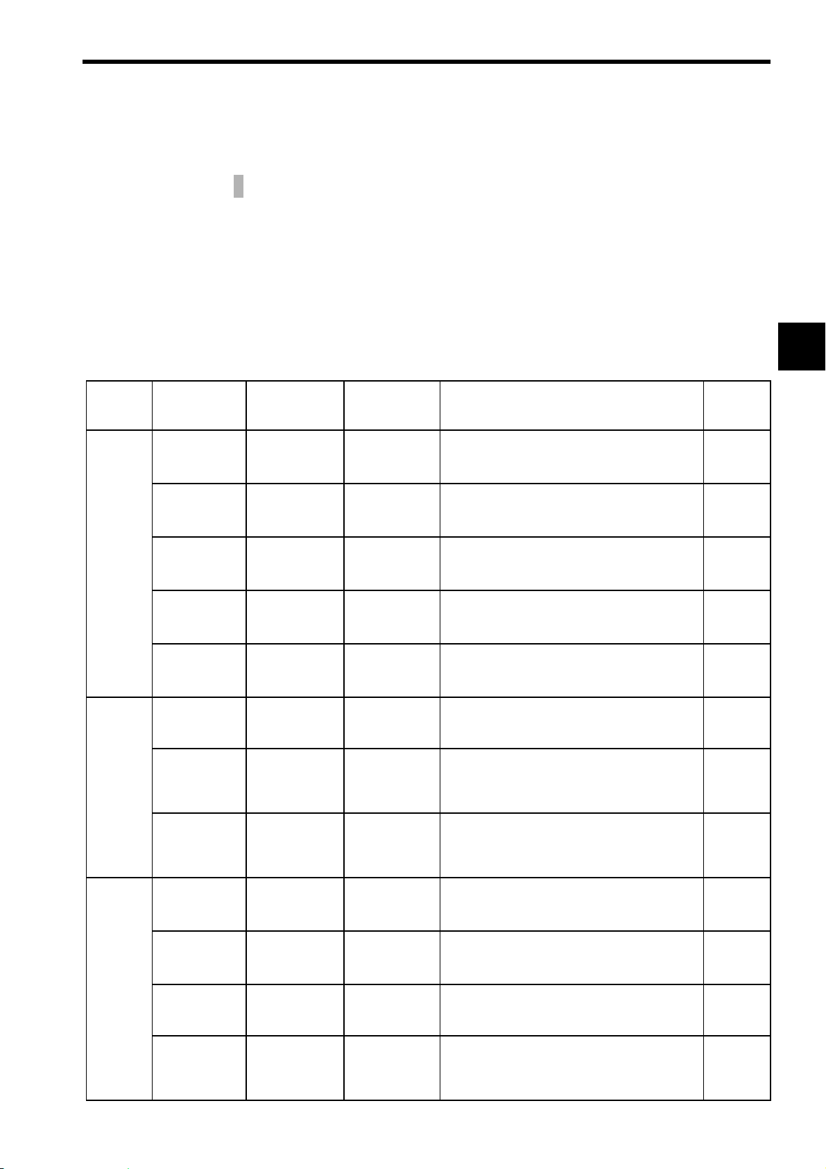
CAUTION
• The following CPU Modules, Remote I/O Receiver Modules, and MEMOSOFT versions are required to use DC 64-point I/O Modules.
Using a version that is not recommended may result in failure or malfunction.
Name Model
Name
CPU Module
(8 kW)
CPU Module
(16 kW)
CPU Module
(16 kW)
CPU Module
(32 kW)
CPU Module
(40 kW)
Remote I/O
Receiver
Module
MEMOSOFT FMSGL-AT3
CPU10 DDSCR-
CPU20 DDSCR-
CPU21 DDSCR-
CPU30 DDSCR-
CPU35 DDSCR-
RIORCOAX
Model No. Version Number Location of
Version Number
A01 and later Module nameplate
120CPU14200
B05 and later Module nameplate
120CPU34100
A01 and later Module nameplate
120CPU34110
B05 and later Module nameplate
120CPU54100
A01 and later Module nameplate
120CPU154110
JAMSC120CRR13100
(for English
DOS)
FMSGL-PP3E
(for P120
English version)
A10 and later Module nameplate
1.21 and later In the middle at the
bottom of the
MEMOSOFT
startup screen.
1
* The nameplate is on the right side of the Module.
1-13
Page 19

1 Introduction and Precautions
1.2.6 Maintenance
1.2.6 Maintenance
CAUTION
CAUTION
CAUTION
CAUTION
CAUTION
• Do not disassemble or modify Modules and Mounting Bases.
Failure to observe this caution may result in fire, product failure, or malfunction.
• Do not replace the built-in fuses of the AC 16-point Output Modules.
If the built-in fuses are replaced by anyone other than a Yaskawa-approved
technician, a failure or a malfunction may occur in the AC 16-point Output Modules, and the guarantee is void.
• Do not replace the built-in fuses of the DC 8-point Output Modules.
If the built-in fuses are replaced by anyone other than a Yaskawa-approved
technician, a failure or malfunction may occur in the DC 8-point Output Modules,
and the guarantee is void.
• Do not replace the built-in fuses of the DC 32-point Output Modules.
If the built-in fuses are replaced by anyone other than a Yaskawa-approved
technician, a failure or malfunction may occur in the DC 32-point Output Modules, and the guarantee is void.
• Do not replace the built-in fuses of the DC 64-point Output Modules.
CAUTION
If the built-in fuses are replaced by anyone other than a Yaskawa-approved
technician, a failure or malfunction may occur in the DC 64-point Output Modules, and the guarantee is void.
• Do not replace the built-in fuses of the Register I/O Modules.
If the built-in fuses are replaced by anyone other than a Yaskawa-approved
technician, a failure or malfunction may occur in the Register I/O Modules, and
the guarantee is void.
1-14
Page 20

1.3 Using This Manual
This manual is written for those who already have a basic knowledge of MEMOCON
PLCs. We recommended reading the MEMOCON GL120, GL130 Hardware User’s
Manual (manual No. SIEZ-C825-20.1) before attempting to read this manual.
• Meaning of Basic Terms
1.3 Using This Manual
In this manual, the following terms indicate the meanings as described below,
unless otherwise specified.
Terms Meaning Remarks
PLC Programmable (Logic) Controller Does not mean “personal
computer.”
PP Programming Panel −
GL120, GL130 MEMOCON GL120 and MEMOCON GL130
Programmable Controllers
AC I/O
Module
DC I/O
Module
Analog
I/O
Module
Register I/O Module Register Input Module −
AC input
Module
AC output
Module
DC input
Module
DC output
Module
Analog
input Module
Analog
output Module
100-VAC 16-point Input Module
200-VAC 16-point Input Module
100/200-VAC 8-point Output Module
100/200-VAC 16-point Output Module
Relay Contact 16-point Output Module*
12/24-VDC 16-point Input Module
12/24-VDC 32-point Input Module
12/24-VDC 64-point Input Module
12/24-VDC 8-point Output Module
12/24-VDC 16-point Output Module
12/24-VDC 32-point Output Module
12/24-VDC 64-point Output Module
Relay contact 16-point Output Module*
Analog Input Module (±10V, 4CH)
Analog Input Module (0 to 10V, 4CH)
Analog Input Module (4 to 20mA, 4CH)
Analog Output Module (±10V, 2CH)
Analog Output Module (0 to 10V, 2CH)
Analog Output Module (0 to 5V, 2CH)
Analog Output Module (4 to 20mA, 2CH)
Register Output Module
2
−
−
*1 When the AC load is
applied.
1
−
*2 When the DC load is
applied.
−
−
1
TERMS
• Description of Technical Terms
The bold technical terms in this manual are briefly explained in the Glossary
provided at the bottom of the page. An example is shown below.
Glossary
The following types of terms are described.
• Specific sequence control terms required for explanation of functions.
• Terms that are specific to programmable controllers and electronic devices.
1-15
Page 21

Models and General Specifications of I/O Modules
This chapter describes the models and general specifications of I/O
Modules.
2.1 General Specifications - - - - - - - - - - - - - - - - - - - - - - - - - - -2-2
2.2 I/O Modules - - - - - - - - - - - - - - - - - - - - - - - - - - - - - - - - - - -2-3
2.2.1 Models of I/O Modules - - - - - - - - - - - - - - - - - - - - - - - 2-3
2.2.2 Overview of I/O Module Specifications - - - - - - - - - - - - 2-5
2.2.3 Using I/O Modules - - - - - - - - - - - - - - - - - - - - - - - - - 2-10
2
2
2-1
Page 22

2 Models and General Specifications of I/O Modules
2.1 General Specifications
This section gives the general specifications of I/O Modules.
Item Specification
Environmental
Conditions
Mechanical
Operating
Conditions
Electrical
Operating
Conditions
Installation
Requirements
Ambient Operating Temperature 0 °C to 60 °C
Ambient Storage Temperature -25 C° to 85 °C (excluding battery)
Ambient Operating Humidity 30 % to 95 % RH (with no condensation)
Ambient Storage Humidity 5 % to 95 % RH (with no condensation)
Pollution Level Pollution level 1 (according to JIS B3502)
Corrosive Gas No corrosive gas
Operating Altitude Less than 2,000 m above sea level
Vibration Shock 10 to 57 Hz with half-amplitude of 0.075mm
Shock Resistance
Noise Resistance 1,500 V in either normal or common mode with pulse
Ground Ground to 100 Ω or less
Configuration Building-block, wall-mounted, or DIN track mounted
Cooling Method Natural cooling
Mass See specifications for individual I/O Modules.
External Dimensions See specifications for individual I/O Modules.
Table 2.1 General Specifications
57 to 150 Hz with fixed acceleration of 9.8 m/s
10 sweep times each in X, Y, and Z directions
(sweep time: 1 octave/min) (according to JIS B3502)
Peak acceleration of 147 m/s
and Z directions (according to JIS B3502)
widths of 100 ns and 1 µs and rise time of 1 ns (with
impulse noise simulator) (according to JIS B3502)
2
2
twice for 11 ms in X, Y,
2-2
Page 23
2.2 I/O Modules
2.2 I/O Modules
This section describes various input modules and output modules.
2.2.1 Models of I/O Modules - - - - - - - - - - - - - - - - - - - - - - - - - - - - - - - - - -2-3
2.2.2 Overview of I/O Module Specifications - - - - - - - - - - - - - - - - - - - - - - -2-5
2.2.3 Using I/O Modules - - - - - - - - - - - - - - - - - - - - - - - - - - - - - - - - - - - -2-10
2.2.1 Models of I/O Modules
Twenty models of I/O Modules are available.
Table 2.2 I/O Modules
Product Name Model Name Model No. Features Number
of slots
required
Digital
Input
Modules
Analog
Input
Modules
Digital
Output
Modules
100-VAC
16-point Input
Module
200-VAC
16-point Input
Module
12/24-VDC
16-point Input
Module
12/24-VDC
32-point Input
Module
12/24-VDC
64-point Input
Module
Analog Input
Module (±10V,
4 channels)
Analog Input
Module (0 to
10V, 4 channels)
Analog Input
Module (4 to
20mA, 4 channels)
100/200-VAC
8-point
Output Module
100/200-VAC
16-point
Output Module
12/24-VDC 8point Output
Module
12/24-VDC
16-point Output Module
(sinking)
AC100IN-16P JAMSC-
120DAI54300
AC200IN-16P JAMSC-
120DAI74300
DC24IN-16P JAMSC-
120DDI34300
DC24IN-32P JAMSC-
120DDI35400
DC24IN-64P JAMSC-
120DDI36400
A/D-VOL4CH
A/D 0-10V
4CH
A/D-CUR4CH
ACOUT-8P JAMSC-
ACOUT-16P JAMSC-
DC24OUT-8P JAMSC-
DC24OUT16PSN
JAMSC120AVI02000
JAMSC120AVI02100
JAMSC120ACI02000
120DAO83000
120DAO84300
120DDO33000
JAMSC120DDO34310
1) Used to input digital signals.
2) 100VAC, 16 points, 7mA (50Hz)
1) Used to input digital signals.
2) 200VAC, 16 points, 7mA (50Hz)
1) Used to input digital signals.
2) 12/24VDC, 16 points, 4mA (12VDC), 8mA
(24VDC)
1) Used to input digital signals.
2) 12/24VDC, 32 points, 2mA (12VDC), 4mA
(24VDC)
1) Used to input digital signals.
2) 12/24VDC, 64 points, 2mA (12VDC), 4mA
(24VDC)
1) Used to input analog signals.
2) -10 to 10V, 4 channels
1) Used to input analog signals.
2) 0 to 10V, 4 channels
1) Used to input analog signals.
2) 4 to 20mA/1 to 5V, 4 channels
1) Used to output digital signals.
2) 100/200VAC, 8 points, 1.0 A/point
1) Used to output digital signals.
2) 100/200VAC, 16 points, 0.3 A/point
1) Used to output digital signals.
2) 12/24VDC, 8 points, sourcing/sinking
outputs, 2.0 A/point
1) Used to output digital signals.
2) 12/24VDC, 16 points, sinking outputs, 0.5
A/point, 1.0 A/4points
1
1
1
1
1
1
1
1
1
1
1
1
2
2-3
Page 24

2 Models and General Specifications of I/O Modules
2.2.1 Models of I/O Modules
Table 2.2 I/O Modules
Product Name Model Name Model No. Features Number
of slots
required
Digital
Output
Modules
12/24-VDC
16-point Output Module
DC24OUT16PSR
JAMSC120DDO34320
1) Used to output digital signals.
2) 12/24VDC, 16 points, sourcing outputs,
0.5 A/point, 1.0 A/4points
1
(sourcing)
12/24-VDC
32-point Output Module
DC24OUT32PSN
JAMSC120DDO35410
1) Used to output digital signals.
2) 12/24VDC, 32 points, sinking outputs, 0.3
A/point, 0.4 A/4points
1
(sinking)
12/24-VDC
64-point Output Module
DC24OUT64PSN
JAMSC120DDO36410
1) Used to output digital signals.
2) 12/24VDC, 64 points, sinking outputs, 0.1
A/point
1
(sinking)
Relay Contact
16-point Out-
RELAY-16P JAMSC-
120DRA84300
1) Used to output digital signals.
2) Relay contacts, 16 points, 1.0 A/point
1
put Module
Analog
Output
Modules
Analog Output Module
(±10V, 2 chan-
D/A-VOL-2CH JAMSC-
120AVO01000
1) Used to output analog signals.
2) -10 to 10V, 2 channels
1
nels)
Analog Output Module
D/A 0-10V 2CH JAMSC-
120AVO01100
1) Used to output analog signals.
2) 0 to 10V, 2 channels
1
(0 to 10V, 2
channels)
Analog Output Module
D/A 0-5V 2CH JAMSC-
120AVO01200
1) Used to output analog signals.
2) 0 to 5V, 2 channels
1
(0 to 5V, 2
channels)
Analog Output Module
D/A-CUR- 2CH JAMSC-
120ACO01000
1) Used to output analog signals.
2) 4 to 20mA, 2 channels
1
(4 to 20mA, 2
channels)
Special
Purpose
Modules
Register Input
Module
REGISTER-IN JAMSC-
120RDI34410
1) Used to input a maximum of 8 sets (8
channel) or 16 sets (16 channel) of 16-bit
or BCD 4-digit values.
1
2) The data input cycle can be selected:
For 8 channels: 10/32/64/192/320 ms
For 16 channels: 20/64/128/384/640 ms
Register Output Module
REGISTEROUT
JAMSC120RDO34410
1) Used to output a maximum of 8 sets (8
channel) or 16 sets (16 channel) of 16-bit
1
or BCD 4-digit values.
2) Select the data output cycle.
For 8-channel: 32/64/192/320 ms
For 16-channel: 64/128/640 ms
Note: The 64-point I/O Modules are limited to versions for the CPU Module, remote I/O
Receiver Module and MEMOSOFT. Refer to 2.2.3 Using I/O Modules for details.
2-4
Page 25
2.2.2 Overview of I/O Module Specifications
1) Digital Input Modules
a) Function
A Digital Input Module converts the digital signals coming from pushbutton switches,
limit switches, and digital switches into signals of appropriate voltage for PLC inter-
nal processing. The converted digital signals are stored by the CPU Module as input
relays and input registers in state memory.
b) Specifications
2.2 I/O Modules
The following table shows the main specifications of Digital Input Modules.
Table 2.3 Main Specifications of Digital Input Modules
Name Model
Name
100-VAC
16-point
Input
Module
200-VAC
16-point
Input
Module
12/24VDC 16point Input
Module
12/24VDC 32point Input
Module
12/24VDC 64point Input
Module
Other Specifications
1) Slots required: 1
2) Width: 40.3 mm Height: 130 mm Depth: 103.9 mm
3) Approx. mass
16-point Input Module: 250 g
32-point Input Module: 250 g
64-point Input Module: 300 g
4) Field connections
16-point Input Module: terminal block
32-point Input Module: connector
64-point Input Module: connector
5) Number of points per common
16-point Input Module: 8 points per common
32-point Input Module: 16 points per common
64-point Input Module: 16 points per common
AC100IN16P
AC200IN16P
DC24IN16P
DC24IN32P
DC24IN64P
Model No. Rated
Vol t-
age
JAMSC120DAI54
300
JAMSC120DAI74
300
JAMSC120DDI34
300
JAMSC120DDI35
400
JAMSC120DDI36
400
100
VAC
200
VAC
12/24
VDC
12/24
VDC
12/24
VDC
Rated
Current
7 mA
(50Hz)
7 mA
(50Hz)
4 mA
(12 VDC)
8 mA
(24 VDC)
2 mA
(12 VDC)
4 mA
(24 VDC)
2 mA
(12 VDC)
4 mA
(24 VDC)
Input
Imped-
ance
14.3 kΩ
(50 Hz)
12.5 kΩ
(60 Hz)
28.6 kΩ
(50 Hz)
23.1 kΩ
(60 Hz)
3.0 kΩ OFF→ON:
5.6 kΩ OFF→ON:
5.6 kΩ OFF→ON:
Input
Delay
Times
OFF→ON:
Max. 20 ms
ON→OFF:
Max. 35 ms
OFF→ON:
Max. 20 ms
ON→OFF:
Max. 35 ms
Max. 5 ms
ON→OFF:
Max. 5 ms
Max. 5 ms
ON→OFF:
Max. 5 ms
Max. 5 ms
ON→OFF:
Max. 5 ms
Num-
ber of
inputs
16 With all points
16 With all points
16 With all points
32 With all points
64 With all points
Internal
Current Con-
sumption
ON: 90 mA
ON: 90 mA
ON: 100 mA
ON: 80 mA
ON: 100 mA
Maxi-
mum
Heat-
ing
Value
2.0 W Per-
3.5 W Per-
3.7 W Per-
3.6 W Per-
7.0 W Per-
Hot
Swap-
ping
mitted
mitted
mitted
mitted
mitted
2
2-5
Page 26

2 Models and General Specifications of I/O Modules
2.2.2 Overview of I/O Module Specifications
2) Analog Input Modules
a) Function
An Analog Input Module converts the analog signals coming from weight sensors,
temperature sensors, etc., into numeric data appropriate for PLC internal process-
ing. The converted numeric data is stored by the CPU Module as the input registers
in state memory.
b) Specifications
The following table shows the main specifications of the Analog Input Modules.
Table 2.4 Main Specifications of Analog Input Modules
Name Model
Name
Analog
Input
Module
A/DVOL-
4CH
(±10 V, 4
channels)
Analog
Input
Module
A/D
0-10V
4CH
(0 to
10 V,
4 channels)
Analog
Input
Module (4
A/D-
CUR-
4CH
to 20 mA,
4 channels)
Other Specifications
1) Slots required: 1
2) Approx. mass: 300 g
3) Width: 40.3 mm Height: 130 mm Depth: 103.9 mm
4) Field connections: Terminal block
Model
No.
JAMSC120AVI
02000
JAMSC120AVI
02100
JAMSC120ACI
02000
Input
Signal
Range
-10 to
+10 V
0 to
+10 V
Current
input:
4 to 20
mA
Voltage
input:
1 to 5 V
Overall
Accuracy
±0.5% F.S.
(25°C)
±1.0% F.S.
(0 to 60°C)
±0.5% F.S.
(25°C)
±1.0% F.S.
(0 to 60°C)
±0.5% F.S.
(25 °C)
±1.0% F.S.
(0 to 60°C)
Resolution
0 to 4000
mode: 12 bits,
binary between
0 and 4000
± 2000 mode:
12 bits, 2’s
complement
between -2000
and +2000
12 bits, binary
between 0 and
4000
12 bits, binary
between 0 and
4000
and Data
Typ es
Num-
nels
Internal
Current
Con-
sump-
tion
Input
Impedance
ber of
Chan-
1 MΩ min. 4 450
mA
1 MΩ min. 4 450
mA
Current
input: 250 Ω
4 450
mA
voltage
input: 1 MΩ
min.
Maxi-
mum
Heat-
Hot
Swap-
ping
ing
Value
2.3 W Permitted
2.3 W Permitted
2.3 W Permitted
2-6
Page 27

3) Digital Output Modules
a) Function
A Digital Output Module converts the numeric data stored in output registers or the
ON/OFF state of the output coil in the state memory of the CPU Module into digital
signals for control of indicators, electromagnetic switches, relays, solenoid valves,
numeric indicators, etc.
b) Specifications
The following table shows the main specifications of Digital Output Modules.
2.2 I/O Modules
Name Model
100/200VAC
8-point
Output
Module
100/200VAC
16-point
Output
Module
12/24-VDC
8-point
Output
Module
12/24-VDC
16-point
Output
Module
(sinking)
12/24-VDC
16-point
Output
Module
(sourcing)
12/24-VDC
32-point
Output
Module
(sinking)
12/24-VDC
64-point
Output
Module
(sinking)
Relay contact
16-point
Output
Module
ACOUT
-8P
ACOUT
-16P
DC24O
UT-8P
DC24O
UT16PSN
DC24O
UT16PSR
DC24O
UT32PSN
DC24O
UT64PSN
RELAY16P
Name
Table 2.5 Main Specifications of Digital Output Modules
Model No. Rated
Vol t-
age
JAMSC120DAO83
000
JAMSC120DAO84
300
JAMSC120DDO33
000
JAMSC120DDO34
310
JAMSC120DDO34
320
JAMSC120DDO35
410
JAMSC120DDO36
410
JAMSC120DRA84
300
100/
200
VAC
100/
200
VAC
12/24
VDC
12/24
VDC
12/24
VDC
12/24
VDC
12/24
VDC
Relay
contact
Load
Current
1.0 A/
point
0.6 A/
point
2.0 A/
point
0.5 A/
point,
1.0 A/
4 points
0.5 A/
point,
1.0 A/
4 points
0.3 A/
point,
0.4 A/
4 points
0.1 A/
point
1.0 A/
point
Remarks Output
Delay
Times
Unprotected
outputs
Unprotected
outputs
Short-circuit protection
Sourcing/
sinking
outputs
Unprotected
outputs
Sinking
outputs
Unprotected
outputs
Sourcing
outputs
Unprotected
outputs
Sinking
outputs
Unprotected
output
Sinking
outputs
Unprotected
outputs
OFF→ON:
Max. 5 ms
ON→OFF:
1/2 cycle +
5 ms max.
OFF→ON:
Max. 5 ms
ON→OFF:
1/2 cycle +
5 ms max.
OFF→ON:
Max. 3 ms
ON→OFF:
Max. 5 ms
OFF→ON:
Max. 1 ms
ON→OFF:
Max. 1 ms
OFF→ON:
Max. 1 ms
ON→OFF:
Max. 1 ms
OFF→ON:
Max. 1 ms
ON→OFF:
Max. 1 ms
OFF→ON:
Max. 1 ms
ON→OFF:
Max. 1 ms
OFF→ON:
Max. 10 ms
ON→OFF:
Max. 15 ms
Num
ber
of
Outputs
8 With all
16 With all
8 With all
16 With all
16 With all
32 With all
64 With all
16 With all
Internal
Current Con-
sumption
points ON:
150 mA
points ON:
300 mA
points ON:
220 mA
points ON:
220 mA
points ON:
300 mA
points ON:
330 mA
points ON:
650 mA
points ON:
610 mA
Maximum
Heat-
ing
Val ue
9.0 W Per-
5.5 W Per-
1.6 W Per-
7.1 W Per-
7.5 W Per-
6.5 W Per-
13.0 W Per-
3.1 W Per-
Hot
Swap
ping
mitted
mitted
mitted
mitted
mitted
mitted
mitted
mitted
2
2-7
Page 28

2 Models and General Specifications of I/O Modules
2.2.2 Overview of I/O Module Specifications
Table 2.5 Main Specifications of Digital Output Modules
Name Model
Name
Model No. Rated
Vol t-
Load
Current
Remarks Output
age
Other Specifications
1) Slots required: 1
2) Width: 40.3 mm Height: 130 mm Depth: 103.9 mm
3) Approx. mass
AC Output Module: 300 g
DC Output Module (8-point, 16-point, 32-point): 250 g
DC Output Module (64-point): 300 g
Relay Contact Output Module: 300 g
4) Field connections
8-point Output Module: terminal block
16-point Output Module: terminal block
32-point Output Module: connector
64-point Output Module: connector
Relay Contact Output Module: terminal block
5) Number of points per common
8-point Output Module: Independent outputs
16-point Output Module: 8 points per common
32-point Output Module: 16 points per common
64-point Output Module: 16 points per common
Relay Contact Output Module: 8 points per common
Delay
Times
Num
ber
of
Outputs
Internal
Current Con-
sumption
Maxi-
mum
Heat-
ing
Value
Hot
Swap
ping
2-8
Page 29

4) Analog Output Module
a) Function
An Analog Output Module converts the numeric data stored in output registers in the
state memory of the CPU Module into analog signals for control of heaters, pumps,
PID adjusters, inverters, etc.
b) Specifications
The following table shows the main specifications of the Analog Output Modules.
Table 2.6 Main Specifications of Analog Output Modules
2.2 I/O Modules
Name Model
Name
Analog
Output
Module
(±10 V, 2
channels)
Analog
Output
Module (0
to 10 V, 2
channels)
Analog
Output
Module (0
to 5 V, 2
channels)
Analog
Output
Module (4
to 20 mA,
2 channels)
Other Specifications
1) Slots required: 1
2) Approx. mass : 350 g
3) Width: 40.3 mm Height: 130 mm Depth: 103.9 mm
4) Field connection: Terminal block
D/AVOL2CH
D/A
0-10V
2CH
D/A
0-5V
2CH
D/ACUR2CH
Model
No.
JAMSC120AVO
01000
JAMSC120AVO
01100
JAMSC120AVO
01200
JAMSC120AC
O01000
Output
Signal
Range
-10 to
+10 V
0 to +10 V±0.2% F.S.
0 to +5 V±0.2% F.S.
4 to 20 mA±0.2% F.S.
Overall
Accuracy
±0.2% F.S.
(25 °C)
±0.5% F.S.
(0 to
60 °C)
(25 °C)
±0.5% F.S.
(0 to 60 °C)
(25 °C)
±0.5% F.S.
(0 to 60 °C)
(25 °C)
±0.5% F.S.
(0 to 60 °C)
Resolution and
Data Types
0 to 4000 mode:
12 bits, binary
between 0 and
4000
±2000 mode: 12
bits, 2’s complements between
-2000 and
+2000
12 bits, binary
between 0 and
4000
12 bits, binary
between 0 and
4000
12 bits, binary
between 0 and
4000
Maxi-
mum
Permis-
sible
Load
Current
±5 mA,
2 kΩ
min.
5 mA,
2 kΩ
min.
2.5 mA,
2 kΩ
min.
550 Ω
max.
Number of
Chan-
nels
2 400
2 400
2 400
2 500
Inter-
nal Cur-
rent
Con-
sump-
tion
mA
mA
mA
mA
Maximum
Heat-
ing
Val ue
2.0 W Permit-
2.0 W Permit-
2.0 W Permit-
2.5 W Permit-
Hot
Swap-
ping
ted
ted
ted
ted
2
2-9
Page 30

2 Models and General Specifications of I/O Modules
2.2.3 Using I/O Modules
2.2.3 Using I/O Modules
1) Installation Location of I/O Modules
(1) I/O Modules can be mounted to any slot of the Mounting Base of any Rack.
Each I/O Module occupies one slot.
(2) The following diagram shows an example on where to mount I/O Modules.
EXAMPLE
1234 5 7
PS10 DODI
1 2 3 4 5 7 10 11 12
05
PS10: Power Supply Module (7 A)
PS05: Power Supply Module (3 A)
CPU30: CPU Module (32 kW)
DI: 12/24-VDC 16-point Input Module
DO: 12/24-VDC 16-point Output Module
CPU30
MP
DI DI DI DI DI DO DO DO DO
6
DI
689
89
MC20
10
MC20
MC20: 4-axis Motion Module
EXP: Expander Module
MB12: 12 slot Mounting Base
W0100-02: Rack-to-rack I/O Cable (0.2 m)
Fig. 2.1 Example of Mounting I/O Modules
2) Versions Supporting 64-point I/O Modules
11 12
EXP
EXPDIPS
Slot No.
Rack 1 (CPU Rack)
MB12
W0100-02
Rack 2
MB12
The following CPU Modules, Remote I/O Receiver Modules, and MEMOSOFT ver-
sions are required to user 64-point I/O Modules.
Table 2.7 Versions Supporting 64-point I/O Modules
Name Model
Name
CPU Module
CPU10 DDSCR-120CPU14200 A01 and later Module nameplate
(8 kw)
CPU Module
CPU20 DDSCR-120CPU34100 B05 and later Module nameplate
(16 kw)
CPU Module
CPU21 DDSCR-120CPU34110 A01 and later Module nameplate
(16 kw)
CPU Module
CPU30 DDSCR-120CPU54100 B05 and later Module nameplate
(32 kw)
CPU Module
CPU35 DDSCR-120CPU54110 A01 and later Module nameplate
(40 kw)
Remote I/O
Receiver
RIORCOAX
Module
MEMOSOFT FMSGL-AT3
Model No. Version Number Location of Ver-
sion Number
DDSCR-120CRR13100 A10 and later Module nameplate
1.21 and later In the middle at the
(for English DOS)
FMSGL-PP3E
(for P120 English version)
bottom of the
MEMOSOFT
startup screen
Note: The nameplate is on the right side of the Module.
2-10
Page 31

Digital I/O Specifications
This chapter describes the specifications of Digital I/O Modules.
3
3.1 Digital Input Module specifications - - - - - - - - - - - - - - - - - - - 3-2
3.1.1 100-VAC 16-point Input Module - - - - - - - - - - - - - - - - - - - - - - - - - - - 3-2
3.1.2 200-VAC 16-point Input Module - - - - - - - - - - - - - - - - - - - - - - - - - - - 3-6
3.1.3 12/24-VDC 16-point Input Module - - - - - - - - - - - - - - - - - - - - - - - - 3-10
3.1.4 12/24-VDC 32-point Input Module - - - - - - - - - - - - - - - - - - - - - - - - 3-14
3.1.5 12/24-VDC 64-point Input Module - - - - - - - - - - - - - - - - - - - - - - - - 3-18
3.2 Digital Output Module Specifications - - - - - - - - - - - - - - - - 3-24
3.2.1 100/200-VAC 8-point Output Module - - - - - - - - - - - - - - - - - - - - - - 3-24
3.2.2 100/200-VAC 16-point Output Module - - - - - - - - - - - - - - - - - - - - - - 3-28
3.2.3 12/24-VDC 8-point Output Module - - - - - - - - - - - - - - - - - - - - - - - - 3-32
3.2.4 12/24-VDC 16-point Output Module (Sinking) - - - - - - - - - - - - - - - - 3-36
3.2.5 12/24-VDC 16-point Output Module (Sourcing) - - - - - - - - - - - - - - - 3-40
3.2.6 12/24-VDC 32-point Output Module - - - - - - - - - - - - - - - - - - - - - - - 3-44
3.2.7 12/24-VDC 64-point Output Module - - - - - - - - - - - - - - - - - - - - - - - 3-49
3.2.8 Relay Contact 16-point Output Module - - - - - - - - - - - - - - - - - - - - - 3-55
3.3 I/O Module Cables - - - - - - - - - - - - - - - - - - - - - - - - - - - - - 3-60
3.3.1 I/O Module Cable Types - - - - - - - - - - - - - - - - - - - - - - - - - - - - - - - 3-60
3.3.2 W0300 Cables (Model No. JZMSZ-120W0300-) - - - - - - - - - - - 3-62
3.3.3 W0302 Cables (Model No. JZMSZ-120W0302-) - - - - - - - - - - - 3-65
3.3.4 W0301 Cables (Model No. JZMSZ-120W0301-) - - - - - - - - - - - 3-68
3.3.5 32-point I/O Connector Terminal Block - - - - - - - - - - - - - - - - - - - - - 3-71
3.3.6 W5410 Cables (Model No. JEPMC-W5410-) - - - - - - - - - - - - - - 3-74
3
3.4 I/O Allocation - - - - - - - - - - - - - - - - - - - - - - - - - - - - - - - - - 3-81
3.4.1 16-point Input Modules - - - - - - - - - - - - - - - - - - - - - - - - - - - - - - - - 3-81
3.4.2 32-point Input Modules - - - - - - - - - - - - - - - - - - - - - - - - - - - - - - - - 3-84
3.4.3 64-point Input Modules - - - - - - - - - - - - - - - - - - - - - - - - - - - - - - - - 3-87
3.4.4 8-point Output Modules - - - - - - - - - - - - - - - - - - - - - - - - - - - - - - - - 3-92
3.4.5 16-point Output Modules - - - - - - - - - - - - - - - - - - - - - - - - - - - - - - - 3-94
3.4.6 32-point Output Modules - - - - - - - - - - - - - - - - - - - - - - - - - - - - - - - 3-97
3.4.7 64-point Output Modules - - - - - - - - - - - - - - - - - - - - - - - - - - - - - - 3-101
3.5 Operations Using MEMOSOFT - - - - - - - - - - - - - - - - - - - 3-106
3.5.1 MEMOSOFT Versions Supporting 64-point I/O Modules - - - - - - - - 3-106
3.5.2 Digital Input Module I/O Allocation Screen - - - - - - - - - - - - - - - - - - 3-107
3.5.3 Digital Output Module I/O Allocation Screen - - - - - - - - - - - - - - - - 3-108
3.5.4 I/O Allocations - - - - - - - - - - - - - - - - - - - - - - - - - - - - - - - - - - - - - 3-109
3-1
Page 32

3 Digital I/O Specifications
3.1.1 100-VAC 16-point Input Module
3.1 Digital Input Module specifications
This section describes the performance specifications, circuit configuration, external
connections, and the external appearance of the 120-series Digital Input Modules.
3.1.1 100-VAC 16-point Input Module - - - - - - - - - - - - - - - - - - - - - - - - - - - 3-2
3.1.2 200-VAC 16-point Input Module - - - - - - - - - - - - - - - - - - - - - - - - - - - 3-6
3.1.3 12/24-VDC 16-point Input Module - - - - - - - - - - - - - - - - - - - - - - - - - 3-10
3.1.4 12/24-VDC 32-point Input Module - - - - - - - - - - - - - - - - - - - - - - - - - 3-14
3.1.5 12/24-VDC 64-point Input Module - - - - - - - - - - - - - - - - - - - - - - - - - 3-18
3.1.1 100-VAC 16-point Input Module
1) Performance Specifications
Item Specifications
Name 100-VAC 16-point Input Module
Model Name AC100IN-16P
Model No. JAMSC-120DAI54300
Rated Voltage 100 VAC
Maximum Allowable Voltage 132 VAC
Rated Frequency 50/60 Hz
Allowable Frequency Range 47 to 63 Hz
Inrush Current 160 mA
Rated Current 7 mA (at 100 VAC, 50 Hz)
Input Impedance 14.3 kΩ (at 100 VAC, 50 Hz)
12.5 kΩ (at 100 VAC, 50 Hz)
Standard Operating Ranges ON voltage range: 74 to 132 VAC
OFF voltage range: 30 VAC max.
Input Type AC type2 (according to JIS B3502)
Input Delay Times OFF to ON: 20 ms max.
ON to OFF: 35 ms max.
Number of common 2
Number of Inputs per Common 8 points/common
Input Power Supply per Common Connect power supplies of the same phase to the Common 1 and
Common 2.
External Connections Removable terminal block with M3 screw terminals
Number of Inputs 16
Input Signal Indication Indicator for each point; lit when the input is ON.
Status saved in internal logic.
Status Indication ACTIVE: Lights during input processing
Insulation Method Photocoupler
Dielectric Strength 1,500 VAC for 1 min or 1,800 VAC for 1 s between input terminals and
internal circuits and between all input commons.
Insulation Resistance 100 MΩ min. at room temperature and humidity between input termi-
nals and ground
(measured with a 500-VDC test voltage megohmmeter).
External Power Supply 100 VAC supplied to signals
Derating Conditions None
Internal Current Consumption 90 mA max. at 5 VDC (with all points ON)
3-2
Page 33

Item Specifications
Maximum Heating Value 2.0 W
Hot Swapping
(Removal/insertion under power)
Approx. Mass 250 g
External Dimensions 40.3×130×103.9 mm (W×H×D)
Permitted
2) The following diagram shows the circuit configuration.
Input 1
3.1 Digital Input Module specifications
Input signal
indicator
CAUTION
Input 8
Common 1
100 VAC
Input 9
Input 16
Common 2
100 VAC
Photocoupler
To CPU
Internal circuits
Connect power supplies of the same phase to the Common 1 and Common 2.
If power supplies of different phases are connected, overheating or fire may
occur.
3
3-3
Page 34

3 Digital I/O Specifications
3.1.1 100-VAC 16-point Input Module
3) The following diagram shows an example of terminal connections.
EXAMPLE
Terminals
Input 1
Input 2
Input 3
Input 4
Input 5
Input 6
Input 7
Input 8
Common 1
Not connected.
Input 9
Input 10
Input 11
Input 12
CAUTION
Connect power supplies of the same phase to the Common 1 and Common 2.
Note: (1) Crimp Terminals
Use M3 terminal for crimping to the terminal block.
(2) Recommended Wires
Use wires of 1.3 mm
block.
(3) Terminal 10 and terminal 20 are not connected.
Input 13
Input 14
Input 15
Input 16
Common 2
100 VAC
Not connected.
If power supplies of different phases are connected, overheating or fire may
occur.
2
(AWG16) to 0.5mm2 (AWG20) to connect to the terminal
3-4
Page 35

Color code (pink)
3.1 Digital Input Module specifications
4) External Appearance
Module description (120DAI54300)
LED area
Module mounting screw
(Use a M4 Phillips screwdriver.)
Field wiring terminal
(Use a M3 Phillips screwdriver.)
Removable terminal block
for field connections
Terminal block mounting screw
(Use a M3 Phillips screwdriver.)
Hinged terminal
cover
Signal label insert
3
LED Area
120 DIA 543 00
ACTIVE
1
2
3
4
5
6
7
8
F
9
10
11
12
13
14
15
16
LED Color Indication when ON
ACTIVE Green Processing I/O.
F Red Always not lit.
1 to 16 Green The corresponding LED is lit when
the input signal is ON.
3-5
Page 36

3 Digital I/O Specifications
3.1.2 200-VAC 16-point Input Module
3.1.2 200-VAC 16-point Input Module
1) Performance Specifications
Item Specifications
Name 200-VAC 16-point Input Module
Model Name AC200IN-16P
Model No. JAMSC-120DAI74300
Rated Voltage 200 VAC
Maximum Allowable Voltage 264 VAC
Rated Frequency 50/60 Hz
Allowable Frequency Range 47 to 63 Hz
Inrush Current 320 mA
Rated Current 7 mA (at 200 VAC, 50 Hz)
Input Impedance 28.6 kΩ (at 200 VAC, 50 Hz)
Standard Operating Ranges ON voltage range: 159 to 264 VAC
Input Type AC type 2 (according to JIS B3502)
Input Delay Times OFF to ON: 20ms max.
Number of commons 2
Number of Inputs per Common 8 points/common
Input Power Supply per Common Connect power supplies of the same phases to the Common 1 and
External Connections Removable terminal block with M3 screw terminals
Number of Inputs 16
Input Signal Indication Indicator for each point; lit when the input is ON.
Status Indication ACTIVE: Lights during input processing
Insulation Method Photocoupler
Dielectric Strength 1,500 VAC for 1 min or 1,800 VAC for 1 s between input terminals and
Insulation Resistance 100 MΩ min. at room temperature and humidity between input termi-
External Power Supply 200 VAC supplied to signals
Derating Conditions None
Internal Current Consumption 90 mA max. at 5 VDC (with all points ON)
Maximum Heating Value 3.5 W
Hot Swapping
(Removal/insertion under power)
Approx. Mass 250 g
External Dimensions 40.3×130×103.9 mm (W×H×D)
23.1 kΩ (at 200 VAC, 50 Hz)
OFF voltage range: 40 VAC max.
ON to OFF: 35ms max.
Common 2.
Status saved in internal logic.
internal circuits and between all input commons.
nals and ground
(measured with a 500-VDC test voltage megohmmeter).
Permitted
3-6
Page 37

2) The following diagram shows the circuit configuration.
Input 1
3.1 Digital Input Module specifications
Input signal
indicator
CAUTION
Input 8
Common 1
200 VAC
Input 9
Input 16
Common 2
200 VAC
Photocoupler
To CPU
Internal circuits
Connect power supplies of the same phase to the Common 1 and Common 2.
If power supplies of different phases are connected, overheating or fire may
occur.
3
3-7
Page 38

3 Digital I/O Specifications
3.1.2 200-VAC 16-point Input Module
3) The following diagram shows an example of terminal connections.
EXAMPLE
Terminals
Input 1
Input 2
Input 3
Input 4
Input 5
Input 6
Input 7
Input 8
Common 1
Not connected.
Input 9
Input 10
Input 11
Input 12
Input 13
CAUTION
Connect power supplies of the same phase to the Common 1 and Common 2.
Note: (1) Crimp Terminals
Use M3 terminal for crimping to the terminal block.
(2) Recommended Wires
Use wires of 1.3 mm
block.
(3) Terminal 10 and terminal 20 are not connected.
Input 14
Input 15
Input 16
Common 2
Not connected.200 VAC
If power supplies of different phases are connected, overheating or fire may
occur.
2
(AWG16) to 0.5mm2 (AWG20) to connect to the terminal
3-8
Page 39

Color code (pink)
LED area
4) External Appearance
Module description (120DAI74300)
Removable terminal block
for field connections
3.1 Digital Input Module specifications
Hinged terminal
cover
Signal label insert
3
Module mounting screw
(Use a M4 Phillips screwdriver.)
LED Area
120 DIA 743 00
ACTIVE
1
2
3
4
5
6
7
8
F
9
10
11
12
13
14
15
16
Field wiring terminal
(Use a M3 Phillips screwdriver.)
Terminal block mounting screw
(Use a M3 Phillips screwdriver.)
LED Color Indication when ON
ACTIVE Green Processing I/O.
F Red Always not lit.
1 to 16 Green The corresponding LED is lit when
the input signal is ON.
3-9
Page 40

3 Digital I/O Specifications
3.1.3 12/24-VDC 16-point Input Module
3.1.3 12/24-VDC 16-point Input Module
1) Performance Specifications
When 12-VDC Modules are used, the specifications do not comply with JIS B3502.
Name 12/24 VDC 16-point Input Module
Model Name DC24IN-16P
Model No. JAMSC-120DDI34300
Rated Voltage 12/24 VDC
Maximum Allowable Voltage 30 VDC
Input Form Sourcing or sinking
Rated Current 4 mA 8 mA
Input Impedance 3.0 kΩ
Standard Operating Ranges ON voltage range: 9 VDC
Input Type Not covered under JIS
Input Delay Times OFF to ON: 5 ms max.
Number of Commons 2
Number of Inputs per Common 8 points/common
External Connections Removable terminal block with M3 screw terminals
Number of Inputs 16
Input Signal Indication Indicator for each point; lit when the input is ON.
Status Indication ACTIVE: Lights during input processing
Insulation Method Photocoupler
Dielectric Strength 1,500 VAC for 1 min or 1,800 VAC for 1 s between input
Insulation Resistance 100 MΩ min. at room temperature and humidity between
External Power Supply 12 VDC supplied to signals 24 VDC supplied to signals
Derating Conditions None
Internal Current Consumption 100 mA max. at 5 VDC (with all points ON)
Maximum Heating Value 3.7 W
Hot Swapping
(Removal/insertion under power)
Approximate Mass 250 g
External Dimensions 40.3×130×103.9 mm (W×H×D)
Item Specification
At 12 VDC At 24 VDC
OFF voltage range: 5 VDC
DC type 2 (according to JIS
B3502
ON to OFF: 5 ms max.
Status saved in internal logic.
terminals and internal circuits and between all input commons
input terminals and ground
(measured with a 500-VDC test voltage megohmmeter).
Permitted
B3502)
3-10
Page 41

2) The following diagram shows the circuit configuration.
Input 1
3.1 Digital Input Module specifications
Input signal
indicator
12/24 VDC
12/24 VDC
Input 8
Common 1
Input 9
Input 16
Common 2
Photocoupler
To CPU
Internal circuits
3
3-11
Page 42

3 Digital I/O Specifications
3.1.3 12/24-VDC 16-point Input Module
3) The following diagram shows an example of terminal connections.
EXAMPLE
12/24 VDC
Terminals
Input 1
Input 2
Input 3
Input 4
Input 5
Input 6
Input 7
Input 8
Common 1
Not connected
Input 9
Input 10
Input 11
Input 12
Input 13
12/24 VDC
Note: (1) Crimp Terminals
Use M3 terminal for crimping to the terminal block.
(2) Recommended Wires
Use wires of 0.8 mm
2
(AWG18) to 0.2 mm2 (AWG24) to
connect to the terminal block.
(3) Terminal 10 and terminal 20 are not connected.
(4) The polarity of the external power supply for signals can be
either positive or negative.
Input 14
Input 15
Input 16
Common 2
Not connected
3-12
Page 43

Color code
(light blue)
LED area
4) External Appearance
Module description (120DDI34300)
Removable terminal block
for field connections
3.1 Digital Input Module specifications
Hinged terminal
cover
Signal label insert
3
Module mounting screw
(Use a M4 Phillips screwdriver.)
LED Area
120 DDI 343 00
ACTIVE
1
2
3
4
5
6
7
8
F
9
10
11
12
13
14
15
16
Field wiring terminal
(Use a M3 Phillips screwdriver.)
Terminal block mounting screw
(Use a M3 Phillips screwdriver.)
LED Color Indication when ON
ACTIVE Green Processing I/O.
F Red Always not lit.
1 to 16 Green The corresponding LED is lit when
the input signal is ON.
3-13
Page 44

3 Digital I/O Specifications
3.1.4 12/24-VDC 32-point Input Module
3.1.4 12/24-VDC 32-point Input Module
1) Performance Specifications
When 12VDC Modules are used, the specifications do not comply with JIS B3502.
Name 12/24-VDC 32-point Input Module
Model Name DC24IN-32P
Model No. JAMSC-120DDI35400
Rated Voltage 12/24 VDC
Maximum Allowable Voltage 30 VDC
Input Form Sourcing or sinking
Rated Current 2 mA 4 mA
Input Impedance 5.6 kΩ
Standard Operating Ranges ON voltage range: 9 VDC
Input Type Not covered under JIS
Input Delay Times OFF to ON: 5 ms max.
Number of Commons 2
Number of Inputs per Common 16 points/common
External Connections 40-pin connector: one piece
Number of Inputs 32
Input Signal Indication Indicator for each point; lit when the input is ON.
Status Indication ACTIVE: Lights during input processing
Insulation Method Photocoupler
Dielectric Strength 1,500 VAC for 1 min or 1,800 VAC for 1 s between input
Insulation Resistance 100 MΩ min. at room temperature and humidity between
External Power Supply 12 VDC supplied to signals 24 VDC supplied to signals
Derating Conditions None
Internal Current Consumption 80 mA max. at 5 VDC (with all points ON)
Maximum Heating Value 3.6 W
Hot Swapping
(Removal/insertion under power)
Approximate Mass 250 g
External Dimensions 40.3×130×103.9 mm (W×H×D)
Item Specification
At 12 VDC At 24 VDC
OFF voltage range: 5VDC
DC type 2 (according to JIS
B3502
ON to OFF: 5 ms max.
Connector: 10340-52A2JL (made by 3M)
Status saved in internal logic.
terminals and internal circuits and between all input commons
input terminals and ground
(measured with a 500-VDC test voltage megohmmeter).
Permitted
B3502)
3-14
Page 45

2) The following diagram shows the circuit configuration.
Input 1
Input 2
Input 15
3.1 Digital Input Module specifications
Input signal
indicator
Input 16
Common 1
12/24 VDC
Input 17
Input 18
Input 31
Input 32
Common 2
Photocoupler
To CPU
Internal circuits
3
12/24 VDC
3-15
Page 46

3 Digital I/O Specifications
3.1.4 12/24-VDC 32-point Input Module
3) The following diagram shows an example or terminal connections.
EXAMPLE
12/24 VDC
12/24 VDC
Pin No.
Not
connected
Input 32
Input 30
Input 28
Input 26
Input 24
Input 22
Input 20
Input 18
Not
connected
Input 16
Input 14
Common 2
Common 1
Pin No.
Not
connected
Input 31
Input 29
Input 27
Input 25
Input 23
Input 21
Input 19
Input 17
Not
connected
Input 15
Input 13
Input 12
Input 10
Input 8
Input 6
Input 4
Input 2
Input 11
Input 9
Input 7
Input 5
Input 3
Input 1
Note: (1) Pins 9 and 29, pins 19 and 39 are internally connected.
Connect these pins externally as well. Not connecting
them can cause malfunction.
(2) Connectors for External Connections
On the Module: 10240-52A2JL (manufactured by 3M)
(3) Recommended wires
Use wires of 0.08mm
2
(AWG28) to connect to each pin of
the connector.
(4) The polarity of the external power supply for signals can be
connected with either plus or minus.
(5) Pins 10, 20, 30, and 40 are not connected.
(6) External Connection Cable
Use a 32-point I/O Module Cable to connect to field
devices. Refer to 3.3 I/O Module Cables for details.
3-16
Page 47

4) External Appearance
Module description
(120DDI35400)
Color code
(light blue)
LED area
3.1 Digital Input Module specifications
Hinged terminal cover Signal label insert
3
(Use a M4 Phillips screwdriver.)
LED Area
120 DDI 354 00
ACTIVE
9
1
10
2
11
3
12
4
13
5
14
6
15
7
16
8
17
18
19
20
21
22
23
24
25
26
27
28
29
30
31
32
5) Special Purpose Components
The following components must be purchased separately.
• 32-point I/O Module Cable Type: JZMSZ-120W0300-
or
• 32-point I/O Module Cable Type: JZMSZ-120W0302-
or
32-point I/O Module cable connectorModule mounting screw
LED Color Indication when ON
ACTIVE Green Processing I/O.
1 to 32 Green The corresponding LED is lit when the input
signal is ON.
• 32-point I/O Module Cable Type: JZMSZ-120W0301-
Terminal block connector for 32-point I/O type: XW2B-40F5-P (manufactured by
OMRON)
3-17
Page 48

3 Digital I/O Specifications
3.1.5 12/24-VDC 64-point Input Module
Note: (1) The symbol “ -” in the type stands for length for the cable. See 3.3 I/O Mod-
ule Cables for details.
(2) The terminal block number for the 32-point I/O connector type (manufactured
by OMRON) is not that same as that for the 12/24-VDC 32-point Output Module. Refer to 3.3 I/O Module Cables for details.
3.1.5 12/24-VDC 64-point Input Module
1) Performance Specifications
The Module does not conform to JIS B3502 when used as a 12-VDC Module.
Name 12/24-VDC 64-point Input Module
Model Name DC24IN-64P
Model No. JAMSC-120DDI36400
Rated Voltage 12/24 VDC
Maximum Allowable
Voltage
Input Form Sourcing or sinking
Rated Current 2 mA 4 mA
Input Impedance 5.6 kΩ
Standard Operating
Ranges
Input Type Does not conform to JIS B3502. DC type 2 (according to JIS B3502)
Input Delay Times OFF to ON: 5 ms max.
Number of Commons 4
Number of Inputs per
Common
External Connections 40-pin connector: 2 pieces
Number of Inputs 64
Input Signal Indication
Status Indication ACTIVE: Lights during input processing
Insulation Method Photocoupler
Dielectric Strength 1,500 VAC for 1 min or 1,800 VAC for 1 s between input terminals and
Insulation Resistance 100 MΩ min. at room temperature and humidity between input terminals
External Power Supply
Derating Conditions None
Internal Current Consumption
Maximum Heating
Val ue
Item Specification
At 12 VDC At 24 VDC
30 VDC
Minimum ON voltage: 9 VDC
Maximum OFF voltage: 5 VDC
ON to OFF: 5 ms max.
16 points/common
Connector type: FCN-365P040 (made by Fujitsu)
Indicator for each point; lit when the input is ON.
Status saved in internal logic.
32 indicators controlled by toggle switches
internal circuits and between all input commons
and ground (measured with a 500-VDC test voltage megohmmeter).
12 VDC supplied to signals 24 VDC supplied to signals
100 mA max. at 5 VDC (with all points ON)
7.0 W
3-18
Page 49

Item Specification
At 12 VDC At 24 VDC
Hot Swapping
Permitted
(Removal/insertion
under power)
Approximate Mass 300 g
External Dimensions 40.3×130×103.9 mm (W×H×D)
2) The following diagram shows the circuit configuration.
CN1 connector pin
Input 1
Input 2
Input 15
numbers
3.1 Digital Input Module specifications
3
Input signal
indicator
12/24 VDC
Input 16
Common 1
Input 17
Input 18
Input 31
Input 32
Photocoupler
To
CPU
Internal circuits
Common 2
12/24 VDC
(Continued on next page)
3-19
Page 50

3 Digital I/O Specifications
3.1.5 12/24-VDC 64-point Input Module
(Continued from previous page)
Input 33
Input 34
Input 47
Input 48
Common 3
12/24 VDC
Input 49
CN2 connector pin
numbers
Photocoupler
Input signal
indicator
To
Internal circuits
CPU
12/24 VDC
Input 50
Input 63
Input 64
Common 4
3-20
Page 51

EXAMPLE
3.1 Digital Input Module specifications
3) The following diagram shows an example of terminal connections.
12/24 VDC
12/24 VDC
CN1 connector
pin numbers
Not
connected
Common 2
Input 32
Input 30
Input 28
Input 26
Input 24
Input 22
Input 20
Input 18
Not
connected
Common 2
Input 16
CN1 connector
pin numbers
Not
connected
Common 2
Input 31
Input 29
Input 27
Input 25
Input 23
3
Input 21
Input 19
Input 17
Not
connected
Common 1
Input 15
Input 14
Input 12
Input 10
Input 8
Input 6
Input 4
Input 2
(Continued on next page)
Input 13
Input 11
Input 9
Input 7
Input 5
Input 3
Input 1
Note: (1) CN1 pins A9 and B9 and pins A19 and B19 are internally connected. Connect
these pins externally as well. Not connecting them can cause malfunction.
(2) Pins A10, A20, B10, and B20 are not connected.
(3) The polarity of the external power supply for signals can be either positive or
negative.
(4) Connector for External Connections (included)
Connector: FCN-361J040-AU (soldered) (manufactured by Fujitsu Ltd.)
Cover: FCN-360C040-B (manufactured by Fujitsu Ltd.)
(5) Recommended Wires
Use wires of 0.26 mm
2
(AWG23) to connect to each connector pin.
3-21
Page 52

3 Digital I/O Specifications
3.1.5 12/24-VDC 64-point Input Module
(Continued from previous page)
12/24 VDC
12/24 VDC
CN2 connector
pin numbers
Not
connected
Common 4
Input 64
Input 62
Input 60
Input 58
Input 56
Input 54
Input 52
Input 50
Not
connected
Common 3
Input 48
CN2 connector
pin numbers
Not
connected
Common 4
Input 63
Input 61
Input 59
Input 57
Input 55
Input 53
Input 51
Input 49
Not
connected
Common 3
Input 47
Input 46
Input 44
Input 42
Input 40
Input 38
Input 36
Input 34
Input 45
Input 43
Input 41
Input 39
Input 37
Input 35
Input 33
Note: (1) CN2 pins A9 and B9 and pins A19 and B19 are internally connected. Connect
these pins externally as well. Not connecting them can cause malfunction.
(2) Pins A10, A20, B10, and B20 are not connected.
(3) The polarity of the external power supply for signals can be either positive or
negative.
(4) Connector for External Connections (included)
Connector: FCN-361J040-AU (soldered) (manufactured by Fujitsu Ltd.)
Cover: FCN-360C040-B (manufactured by Fujitsu Ltd.)
(5) Recommended Wires
Use wires of 0.26 mm
2
(AWG23) to connect to each connector pin.
(6) External Connection Cable
Two pairs of connectors to connect the external input signal and a 64-point I/O
Module Cable to connect to field devices are provided. For details, refer to 3.3
I/O Module Cables.
3-22
Page 53

4) External Appearance
Module description
(120DDI36400)
Color code
(light blue)
LED area
CN1 connector
3.1 Digital Input Module specifications
Input signal indicator switch
3
120 DDI 364 00
9
1
10
2
11
3
12
4
13
5
14
6
15
7
16
8
CN2 connector
LED Area
ACTIVE
17
18
19
20
21
22
23
24
25
26
27
28
29
30
31
32
Connector and
Module mounting screw
(Use a M4 Phillips screwdriver.)
cover (2 sets)
LED Color Indication when ON Input Signal
Indicator Switch
ACTIVE Green Processing I/O. −
1 to 32 Green Input signal (1 to 32) is ON. Left side (1 to 32)
Input signal (33 to 64) is ON. Right side (33 to 64)
5) Accessories
The following items are included in the accessories.
• Connector for External Connections
Connector: FCN-361J040-AU (soldered) (manufactured by Fujitsu Ltd.)
Cover: FCN-360C040-B (manufactured by Fujitsu Ltd.)
3-23
Page 54

3 Digital I/O Specifications
3.2.1 100/200-VAC 8-point Output Module
3.2 Digital Output Module Specifications
This section describes the performance specifications, circuit configuration, external
connections, and external appearance of the 120-series Digital Output Modules.
3.2.1 100/200-VAC 8-point Output Module - - - - - - - - - - - - - - - - - - - - - - - 3-24
3.2.2 100/200-VAC 16-point Output Module - - - - - - - - - - - - - - - - - - - - - - 3-28
3.2.3 12/24-VDC 8-point Output Module - - - - - - - - - - - - - - - - - - - - - - - - 3-32
3.2.4 12/24-VDC 16-point Output Module (Sinking) - - - - - - - - - - - - - - - - 3-36
3.2.5 12/24-VDC 16-point Output Module (Sourcing) - - - - - - - - - - - - - - - 3-40
3.2.6 12/24-VDC 32-point Output Module - - - - - - - - - - - - - - - - - - - - - - - 3-44
3.2.7 12/24-VDC 64-point Output Module - - - - - - - - - - - - - - - - - - - - - - - 3-49
3.2.8 Relay Contact 16-point Output Module - - - - - - - - - - - - - - - - - - - - - 3-55
3.2.1 100/200-VAC 8-point Output Module
1) Performance Specifications
Item Specifications
Name 100/200-VAC 8-point Output Module
Model Name ACOUT-8P
Model No. JAMSC-120DAO83000
Rated Voltage 100/200 VAC
Allowable Voltage Range 80 to 264 VAC
Rated Frequency 50/60 Hz
Allowable Frequency Range 47 to 63 Hz
Maximum Load Current 1.0 Arms/point
Output Voltage Drop 1.0 Vrms
Output Delay Times OFF to ON: 5 ms max.
ON to OFF: 1/2 cycle + 5 ms max.
OFF Leakage Current 3 mA max. at 240 VAC, 50 Hz
Minimum Load Current 10 mArms
Output Type Triac outputs
Number of Commons 8 (Each output circuit is independent.)
Output Power Supply
per Common
External Connections Removable terminal block with M3 screw terminals
Output Protection Type Unprotected outputs (according to JIS B3502)
Built-in Fuse None
Surge Suppressor Varistor
Other Output Protection None
Number of Outputs 8
Output Signal Indication Indicator for each point; lit when the output is ON.
Status Indication ACTIVE: Lights during input processing.
Insulation Method Phototriac
Dielectric Strength 1,500 VAC for 1 min or 1,800 VAC for 1 s between output terminals and
Possible to connect different power supply phases to the commons.
Status saved in internal logic.
internal circuits and between all output circuits.
3-24
Page 55

3.2 Digital Output Module Specifications
Item Specifications
Insulation Resistance 100 MΩ min. at room temperature and humidity between input termi-
nals and ground
(measured with a 500-VDC test voltage megohmmeter).
External Power Supply 100/200 VAC supplied to drive loads
Derating Conditions None
Internal Current Consumption 50 mA max. at 5 VDC (with all points ON)
Maximum Heating Value 9.0 W
Hot Swapping
(Removal/insertion under power)
Approx. Mass 300 g
External Dimensions 40.3×130×103.9 mm (W×H×D)
Permitted
2) The following diagram shows the circuit configuration.
Output signal
indicator
3
CAUTION
Phototriac
Output 1
From CPU
Internal circuits
100/200 VAC
Output 8
100/200 VAC
If using a 100/200-VAC 8-point Output Module, connect a fuse, which complies with
the load specifications, in series with the load.
A protective fuse does not built into the following 100/200-VAC 8-point Output
Modules. If a fuse is not connected, fire or damage to the devices or output circuits may occur if the load is short-circuited or the circuit overloaded.
3-25
Page 56

3 Digital I/O Specifications
3.2.1 100/200-VAC 8-point Output Module
3) The following diagram shows an example of terminal connections.
EXAMPLE
Output 1
ACIN 1
Output 2
ACIN 2
Output 3
ACIN 3
Output 4
ACIN 4
Not
connected
Not connected
Output 5
ACIN 5
Output 6
ACIN 6
Fuses
LoadsFuses
100/200 VAC
100/200 VAC
100/200 VAC
100/200 VAC
Loads
100/200 VAC
100/200 VAC
CAUTION
If using a 100/200-VAC 8-point Output Module, connect a fuse, which complies with
the load specifications, in series with the load.
A protective fuse does not built into the following 100/200-VAC 8-point Output
Modules. If a fuse is not connected, fire or damage to the devices or output circuits may occur if the load is short-circuited or the circuit overloaded.
Note: (1) Crimp Terminals
Use M3 terminals for crimping to the terminal block.
(2) Recommended Wires
Use wires of 1.3mm
block.
Output 7
ACIN 7
Output 8
ACIN 8
Not
connected
Not connected
2
(AWG16) to 0.5mm2 (AWG20) to connect to the terminal
100/200 VAC
100/200 VAC
3-26
Page 57

4) External Appearance
3.2 Digital Output Module Specifications
Module description (120DAO83000)
Color code
(red)
LED area
Module mounting screw
(Use a M4 Phillips screwdriver.)
Removable terminal block
for field connections
Field wiring terminal
(Use a M3 Phillips screwdriver.)
Hinged terminal
cover
Terminal block mounting screw
(Use a M3 Phillips screwdriver.)
Signal label insert
3
LED Area
120 DAO 830 00
ACTIVE
1
2
3
4
5
6
7
8
LED Color Indication when ON
ACTIVE Green Processing I/O.
1 to 8 Green The corresponding LED is lit when the output
signal is ON.
3-27
Page 58

3 Digital I/O Specifications
3.2.2 100/200-VAC 16-point Output Module
3.2.2 100/200-VAC 16-point Output Module
1) Performance Specifications
Name 100/200-VAC 16-point Output Module
Model Name ACOUT-16P
Model No. JAMSC-120DAO84300
Rated Voltage 100/200 VAC
Allowable Voltage Range 80 to 264 VAC
Rated Frequency 50/60 Hz
Allowable Frequency Range 47 to 63 Hz
Maximum Load Current 0.6 Arms/point, 2.4 A/common
Output Voltage Drop 1.0 Vrms
Output Delay Times OFF to ON: 5 ms max.
OFF Leakage Current 3 mA max. at 240 VAC, 50 Hz
Minimum Load Current 7 mArms
Output Type Triac outputs
Number of Commons 2
Number of Outputs per Common 8 points/common
Output Power Supply per Common Connect power supplies of the same phase to the Common
External Connections Removable terminal block with M3 screw terminals
Output Protection Type Unprotected outputs (according to JIS B3502)
Built-in Fuse Two, 5-A fuses (one per common)
Surge Suppressor Varistor
Other Output Protection None
Number of Outputs 16
Output Signal Indication Indicator for each point; lit when the output the is ON.
Status Indication ACTIVE: Lights during output processing
Insulation Method Phototriac
Dielectric Strength 1,500 VAC for 1 min or 1,800 VAC for 1 s between output
Insulation Resistance 100 MΩ min. (room temperature and humidity) between out-
External Power Supply 100/200 VAC supplied to drive loads
Derating Conditions None
Internal Current Consumption 300 mA max. at 5 VDC (with all points ON)
Maximum Heating Value 5.5 W
Hot Swapping
(Removal/insertion under power)
Approximate Mass 300 g
External Dimensions 40.3×130×103.9 mm (W×H×D)
Item Specifications
ON to OFF: 1/2 cycle + 5 ms max.
1 and Common 2.
(Burnout time: 2 min max. at 200 % of rated current)
Status saved in internal logic.
F: Lights when fuse is burnt out or output power supply is not
connected
terminals and internal circuits and between all output commons
put terminals and ground
(measured with a 500-VDC test voltage megohmmeter).
Permitted
3-28
Page 59

2) The following diagram shows the circuit configuration.
3.2 Digital Output Module Specifications
From CPU
Phototriac
Internal circuits
Blown fuse
detection circuit
Output signal
indicator
Blown fuse
Power not
connected indicator
Fuse
Output 1
Output 8
Common 1-1
Common 1-2
Output 9
Output 16
Common 2-1
Loads
100/200 VAC
3
Loads
CAUTION
CAUTION
CAUTION
100/200 VAC
Common 2-2
Do not replace the built-in fuse of the 100/200-VAC 16-point Output Modules.
If the built-in fuses are replaced by anyone other than a Yaskawa-approved
technician, failure or malfunction may occur in the Modules.
Connect power supplies of the same phase to the Common 1 and Common 2 of the
AC I/O Module.
If power supplies of different phases are connected, overheating or fire may
occur.
If using a 100/200-VAC 16-point Output Module, connect a fuse, which complies with
the load specifications, in series with the load.
A protective fuse built into the following 100/200-VAC 16-point Output Modules
does not protect the output element. If a fuse is not connected, a fire or damage to the devices or output circuits may occur if the load is short-circuited or
the circuit overloaded.
3-29
Page 60

3 Digital I/O Specifications
3.2.2 100/200-VAC 16-point Output Module
3) The following diagram shows an example of terminal connections.
EXAMPLE
Output 1
Output 2
Output 3
Output 4
Output 5
Output 6
Output 7
Output 8
Common 1-1
Common 1-2
Output 9
Output 10
Output 11
Output 12
Output 13
Terminals
Fuses
Fuses
Loads
Loads
CAUTION
CAUTION
Output 14
Output 15
Output 16
Common 2-1
Common 2-2
100/200 VAC
Connect power supplies of the same phase to the Common 1 and Common 2 of the
AC I/O Module.
If power supplies of different phase are connected, overheating or fire may
occur.
If using a 100/200-VAC 16-point Output Module, connect a fuse, which complies with
the load specifications, in series with the load.
A protective fuse built into the following 100/200-VAC 16-point Output Modules
does not protect the output element. If a fuse is not connected, a fire or damage to the devices or output circuits may occur if the load is short-circuited or
the circuit overloaded.
Note: (1) Crimp Terminals
Use M3 terminals for crimping to the terminal block.
(2) Recommended Wires
User wires of 1.3mm
block. Use wires of the size more than 1.3 mm2 (AWG16) for common lines.
2
(AWG16) to 0.5mm2 (AWG20) to connect to the terminal
3-30
Page 61

4) External Appearance
3.2 Digital Output Module Specifications
Color code
(red)
LED area
Module mounting screw
(Use a M4 Phillips screwdriver.)
Field wiring terminal
(Use a M3 Phillips screwdriver.)
Removable terminal block
for field connections
Module description
(120DAO84300)
Hinged terminal
cover
Terminal block mounting screw
(Use a M3 Phillips screwdriver.)
Signal label insert
3
LED Area
120 DAO 843 00
ACTIVE
1
2
3
4
5
6
7
8
F
9
10
11
12
13
14
15
16
LED Color Indication when ON
ACTIVE Green Processing I/O.
F Red Fuse blown out, or external power supply not
connected.
1 to 16 Green The corresponding LED is lit when the output
signal is ON.
3-31
Page 62

3 Digital I/O Specifications
3.2.3 12/24-VDC 8-point Output Module
3.2.3 12/24-VDC 8-point Output Module
1) Performance Specifications
Name 12/24-VDC 8-point Output Module
Model Name DC24OUT-8P
Model No. JAMSC-120DDO33000
Rated Voltage 12/24 VDC
Allowable Voltage Range 10.2 to 30.0 VDC
Output Form Sourcing or sinking
Maximum Load Current 2.0 A/point
Output Voltage Drop 0.1 V max (2.0 A)
Output Delay Times OFF to ON: 3 ms max.
OFF Leakage Current 1 mA max. at 24 VDC
Output Type Transistor (FET) outputs
Number of Commons 8 (Each output circuit is independent.)
External Connections Removable terminal block with M3 screw terminals
Output Protection Type Protected outputs (according to JIS B3502)
Built-in Fuse Eight, 3.5-A fuses (one per circuit)
Surge Suppressor Zener diode
Other Output Protection None
Number of Outputs 8
Output Signal Indication Indicator for each point; lit when the output is ON.
Status Indication ACTIVE: Lights during output processing.
Insulation Method Photocoupler
Dielectric Strength 1,500 VAC for 1 min or 1,800 VAC for 1 s between output
Insulation Resistance 100 MΩ min. at room temperature and humidity between
External Power Supply 12/24 VDC supplied to drive loads
Derating Conditions None
Internal Current Consumption 220 mA max. at 5 VDC (with all points ON)
Maximum Heating Value 1.6 W
Hot Swapping
(Removal/insertion under power)
Approximate Mass 250 g
External Dimensions 40.3×130×103.9 mm (W×H×D)
Item Specifications
ON to OFF: 5 ms max.
(Burnout time: 1 s max. at 200% of rated current)
Status saved in internal logic.
terminals and internal circuits
output terminals (connected together)
(measured with a 500-VDC test voltage megohmmeter).
Permitted
and ground
3-32
Page 63

2) The following diagram shows the circuit configuration.
3.2 Digital Output Module Specifications
From CPU
Photocoupler
Internal circuits
Output signal
indicator
Fuse
Output 1A
Sinking connection
Output 1B
12/24 VDC
Output 2A
12/24 VDC
Output 2B
Sourcing connection
Output 8A
12/24 VDC
Loads
3
Loads
CAUTION
Do not replace the built-in fuses of the DC 8-point Output Modules.
If the built-in fuses are replaced by anyone other than a Yaskawa-approved
technician, a failure or malfunction may occur in the DC 8-point Output Mod-
ules, and the guarantee is void.
CAUTION
If using a 12/24-VDC 8-point Output Module, connect a fuse, which complies with the
load specifications, in series with the load.
A protective fuse built into the following 12/24-VDC 8-point Output Modules
does not protect the output element. If a fuse is not connected, a fire or dam-
age to the devices or output circuits may occur if the load is short-circuited or
the circuit overloaded.
Note: A blown-fuse detection circuit is not built into the circuit. If no output current flows
while the output signal indicator is lit under the rated voltage, the built-in fuse may
be blown. The built-in fuse must be replaced by a Yaskawa service representative.
Output 8B
Loads
3-33
Page 64

3 Digital I/O Specifications
3.2.3 12/24-VDC 8-point Output Module
3) The following diagram shows an example of terminal connections.
EXAMPLE
Output 1A
Output 1B
Output 2A
Output 2B
Output 3A
Output 3B
Output 4A
Output 4B
Not
connected
Not connected
Loads
12/24 VDC
12/24 VDC
12/24 VDC
12/24 VDC
Sinking connection
Sourcing connection
CAUTION
Output 5A
Output 5B
Output 6A
Output 6B
Output 7A
Output 7B
Output 8A
Output 8B
Not
connected
Not connected
Loads
12/24 VDC
12/24 VDC
12/24 VDC
12/24 VDC
If using a 12/24-VDC 8-point Output Module, connect a fuse, which complies with the
load specifications, in series with the load.
A protective fuse built into the following 12/24-VDC 8-point Output Modules
does not protect the output element. If a fuse is not connected, a fire or damage to the devices or output circuits may occur if the load is short-circuited or
the circuit overloaded.
Note: (1) Crimp Terminals
Use M3 crimp terminals for the terminal block.
(2) Recommended Wires
Use wires of 0.8 mm
2
(AWG18) to 0.2 mm2 (AWG24) to connect to the terminal
block.
(3) A blown-fuse detection circuit is not built into the circuit. If no output current
flows while the output signal indicator is lit under the rated voltage, the built-in
fuse may be blown. The built-in fuse must be replaced by a Yaskawa service
representative.
3-34
Page 65

4) External Appearance
3.2 Digital Output Module Specifications
Module description (120DDO33000)
Color code
(dark blue)
LED area
Module mounting screw
(Use a M4 Phillips screwdriver.)
Removable terminal block
for field connections
Field wiring terminal
(Use a M3 Phillips screwdriver.)
Hinged terminal
cover
Terminal block mounting screw
(Use a M3 Phillips screwdriver.)
Signal label insert
3
LED Area
120 DDO 330 00
ACTIVE
1
2
3
4
5
6
7
8
LED Color Indication when ON
ACTIVE Green Processing I/O.
1 to 8 Green The corresponding LED is lit when the output
signal is ON.
3-35
Page 66

3 Digital I/O Specifications
3.2.4 12/24-VDC 16-point Output Module (Sinking)
3.2.4 12/24-VDC 16-point Output Module (Sinking)
1) Performance Specifications
Item Specifications
Name 12/24 VDC 16-point Output Module
Model Name DC24OUT-16PSN
Model No. JAMSC-120DDO34310
Rated Voltage 12/24 VDC
Allowable Voltage Range 10.2 to 30.0 VDC
Output Form Sinking
Maximum Load Current 0.5 A/point, 1.0 A/4 points
Output Voltage Drop 1.5 V max (0.5 A)
Output Delay Times OFF to ON: 1 ms max.
OFF Leakage Current 1 mA max. at 24 VDC
Output Type Transistor outputs
Number of Commons 2
Number of Outputs per Common 8 points/common
External Connections Removable terminal block with M3 screw terminals
Output Protection Type Unprotected outputs (according to JIS B3502)
Built-in Fuse Two, 4-A fuses (one per common)
Surge Suppressor None
Other Output Protection None
Number of Outputs 16
Output Signal Indication Indicator for each point; lit when the output is ON.
Status Indication ACTIVE: Lights during output processing
Insulation Method Photocoupler
Dielectric Strength 1,500 VAC for 1 min or 1,800 VAC for 1 s between output
Insulation Resistance 100 MΩ min. at room temperature and humidity between
External Power Supply 12/24 VDC supplied to drive loads
Derating Conditions None
Internal Current Consumption 220 mA max. at 5 VDC (with all points ON)
Maximum Heating Value 7.1 W
Hot Swapping
(Removal/insertion under power)
Approximate Mass 250 g
External Dimensions 40.3×130×103.9 mm (W×H×D)
ON to OFF: 1 ms max.
(Burnout time: 5 s max. at 200% of rated current)
Status saved in internal logic.
F: Lights when fuse is burnt out or output power supply is not
connected
terminals and internal circuits and between all output commons
output terminals and ground (measured with a 500-VDC test
voltage megohmmeter).
Permitted
3-36
Page 67

2) The following diagram shows the circuit configuration.
3.2 Digital Output Module Specifications
From CPU
Output signal
indicator
Photocoupler
Internal circuits
Blown fuse
detection circuit
Blown fuse
Power not
connected
indicator
Fuse
Output 1
Output 8
-Common 1
+ Common 1
Output 9
Output 16
- Common 2
Loads
12/24 VDC
3
Loads
CAUTION
+ Common
12/24 VDC
If using a 12/24-VDC 16-point Output Module (sinking), connect a fuse, which
complies with the load specifications, in series with the load.
A protective fuse built into the following 12/24-VDC 16-point Output Modules
does not protect the output element. If a fuse is not connected, a fire or dam-
age to the devices or output circuits may occur if the load is short-circuited or
the circuit overloaded.
3-37
Page 68

3 Digital I/O Specifications
3.2.4 12/24-VDC 16-point Output Module (Sinking)
3) The following diagram shows an example of terminal connections.
EXAMPLE
Output 1
Output 2
Output 3
Output 4
Output 5
Output 6
Output 7
Output 8
- Common 1
+ Common 1
Output 9
Output 10
Output 11
Output 12
Terminals
Fuse
Fuse
Loads
12/24 VDC
Loads
CAUTION
CAUTION
Output 13
Output 14
Output 15
Output 16
- Common 2
+ Common 2
12/24 VDC
Although a 0.5 A load can be connected to each output point of the 12/24-VDC 16point Output Module (sinking), the total load must be 1.0A or less for each of the four
output points shown in the shaded areas. Keep the load distribution within the 1.0A
limit.
It this limit is exceeded, damage may occur to the output circuit.
If using a 12/24-VDC 16-point Output Module (sinking), connect a fuse, which
complies with the load specifications, in series with the load.
A protective fuse built into the following 12/24-VDC 16-point Output Modules
does not protect the output element. If a fuse is not connected, a fire or damage to the devices or output circuits may occur if the load is short-circuited or
the circuit overloaded.
Note: (1) Crimp Terminals
Use M3 terminals for crimping to the terminal block.
(2) Recommended Wires
Use wires of 0.8mm
block.
2
(AWG18) to 0.2mm2 (AWG24) to connect to the terminal
3-38
Page 69

Color code
(dark blue)
LED area
4) External Appearance
Module description
(120DDO34310)
Removable terminal block
for field connections
3.2 Digital Output Module Specifications
Hinged terminal cover
Signal label insert
3
Module mounting screw
(Use a M4 Phillips screwdriver.)
LED Area
120 DDO 343 10
ACTIVE
1
2
3
4
5
6
7
8
INFO
F
9
10
11
12
13
14
15
16
• Users can replace the fuses.
5) Spare Parts
Field wiring terminal
(Use a M3 Phillips screwdriver.)
Terminal block mounting screw
(Use a M3 Phillips screwdriver.)
LED Color Indication when ON
ACTIVE Green Processing I/O.
F Red Fuse blown out, or external power supply not
connected.
1 to 16 Green The corresponding LED is lit when the output
signal is ON.
Reserve the following spare part for maintenance.
Fuse Type: 235004 (LITTEL FUSE)
3-39
Page 70

3 Digital I/O Specifications
3.2.5 12/24-VDC 16-point Output Module (Sourcing)
3.2.5 12/24-VDC 16-point Output Module (Sourcing)
1) Performance Specifications
Item Specifications
Name 12/24-VDC 16-point Output Module (Sourcing)
Model Name DC24OUT-16PSR
Model No. JAMSC-120DDO34320
Rated Voltage 12/24 VDC
Allowable Voltage Range 10.2 to 30.0 VDC
Output Form Sourcing
Maximum Load Current 0.5 A/point, 1.0 A/4 points
Output Voltage Drop 1.5 V max (0.5 A)
Output Delay Times OFF to ON: 1 ms max.
OFF Leakage Current 1 mA max. at 24 VDC
Output Type Transistor outputs
Number of Commons 2
Number of Outputs per Common 8 points/common
External Connections Removable terminal block with M3 screw terminals
Output Protection Type Unprotected outputs (according to JIS B3502)
Built-in Fuse Two, 4-A fuses (one per common)
Surge Suppressor None
Other Output Protection None
Number of Outputs 16
Output Signal Indication Indicator for each point; lit when the output is ON.
Status Indication ACTIVE: Lights during output processing
Insulation Method Photocoupler
Dielectric Strength 1,500 VAC for 1 min or 1,800 VAC for 1 s between output
Insulation Resistance 100 MΩ min. at room temperature and humidity between
External Power Supply 12/24 VDC supplied to drive loads
Derating Conditions None
Internal Current Consumption 300 mA max. at 5 VDC (with all points ON)
Maximum Heating Value 7.5 W
Hot Swapping
(Removal/insertion under power)
Approximate Mass 250 g
External Dimensions 40.3×130×103.9 mm (W×H×D)
ON to OFF: 1 ms max.
(Burnout time: 5 s max. at 200% of rated current)
Status saved in internal logic.
F: Lights when fuse is burnt out or output power supply is not
connected
terminals and internal circuits and between all output commons
output terminals and ground (measured with a 500-VDC test
voltage megohmmeter).
Permitted
3-40
Page 71

2) The following diagram shows the circuit configuration.
3.2 Digital Output Module Specifications
From CPU
Photocoupler
Internal circuits
Blown-fuse
detection circuit
Output signal
indicator
Blown fuse/
Power disconnected
indicator
Fuse
Output 1
Output 8
- Common 1
+ Common 1
Output 9
Output 16
Loads
3
12/24 VDC
Loads
CAUTION
- Common 2
+ Common 2
12/24 VDC
If using a 12/24-VDC 16-point Output Module (sourcing), connect a fuse, which
complies with the load specifications, in series with the load.
A protective fuse built into the following 12/24-VDC 16-point Output Modules
does not protect the output element. If a fuse is not connected, a fire or dam-
age to the devices or output circuits may occur if the load is short-circuited or
the circuit overloaded.
3-41
Page 72

3 Digital I/O Specifications
3.2.5 12/24-VDC 16-point Output Module (Sourcing)
3) The following diagram shows an example of terminal connections.
EXAMPLE
Output 1
Output 2
Output 3
Output 4
Output 5
Output 6
Output 7
Output 8
- Common 1
+ Common 1
Output 9
Fuses
12/24 VDC
Fuses
Loads
Loads
CAUTION
CAUTION
Output 10
Output 11
Output 12
Output 13
Output 14
Output 15
Output 16
- Common 2
+ Common 2
12/24 VDC
Although a 0.5 A load can be connected to each output point of the 12/24-VDC 16point Output Module (sourcing), the total load must be 1.0 A or less for each of the
four output points shown in the shaded area. Keep the load distribution within the 1.0
A limit.
It this limit is exceeded, damage may occur to the output circuit.
If using a 12/24-VDC 16-point Output Module (sourcing), connect a fuse, which
complies with the load specifications, in series with the load.
A protective fuse built into the following 12/24-VDC 16-point Output Modules
does not protect the output element. If a fuse is not connected, a fire or damage to the devices or output circuits may occur if the load is short-circuited or
the circuit overloaded.
Note: (1) Crimp Terminals
Use M3 terminals for crimping to the terminal block.
(2) Recommended Wires
Use wires of 0.8mm
block.
2
(AWG18) to 0.2mm2 f(AWG24) to connect to the terminal
3-42
Page 73

4) External Appearance
3.2 Digital Output Module Specifications
Module description (120DDO34320)
Color code
(dark blue)
LED area
Fuse
Module mounting screw
(Use a M4 Phillips screwdriver.)
Removable terminal block
for field connections
Field wiring terminal
(Use a M3 Phillips screwdriver.)
Hinged terminal
cover
Terminal block mounting screw
(Use a M3 Phillips screwdriver.)
Signal label insert
3
LED Area
120 DDO 343 20
ACTIVE
1
2
3
4
5
6
7
8
INFO
5) Spare Parts
LED Color Indication when ON
ACTIVE Green Processing I/O.
F
9
10
11
12
13
14
15
16
F Red Fuse blown out, or external power supply not
connected.
1 to 16 Green The corresponding LED is lit when the output
signal is ON.
• Users can replace the fuses.
Reserve the following spare part for maintenance.
Fuse Type: 235004 (LITTEL FUSE)
3-43
Page 74

3 Digital I/O Specifications
3.2.6 12/24-VDC 32-point Output Module
3.2.6 12/24-VDC 32-point Output Module
1) Performance Specifications
Name 12/24 VDC 32-point Output Module
Model Name DC24OUT-32P
Model No. JAMSC-120DDO35410
Rated Voltage 12/24 VDC
Allowable Voltage Range 10.2 to 30.0 VDC
Output Form Sinking
Maximum Load Current 0.3 A/point, 0.4 A/4 points
Output Voltage Drop 1.5 V max (0.3 A)
Output Delay Times OFF to ON: 1 ms max.
OFF Leakage Current 1 mA max. at 24 VDC
Output Type Transistor outputs
Number of Commons 2
Number of Outputs per Common 16 points/common
External Connections 40-pin connector: one piece
Output Protection Type Unprotected outputs (according to JIS B3502)
Built-in Fuse Two, 3.5-A fuses (one per common)
Surge Suppressor None
Other Output Protection None
Number of Outputs 32
Output Signal Indication Indicator for each point; lit when the output is ON.
Status Indication ACTIVE: Lights during output processing
Insulation Method Photocoupler
Dielectric Strength 1,500 VAC for 1 min or 1,800 VAC for 1 s between output
Insulation Resistance 100 MΩ min. at room temperature and humidity between
External Power Supply 12/24 VDC supplied to drive loads
Derating Conditions None
Internal Current Consumption 330 mA max. at 5 VDC (with all points ON)
Maximum Heating Value 6.5 W
Hot Swapping
(Removal/insertion under power)
Approximate Mass 250 g
External Dimensions 40.3×130×103.9 mm (W×H×D)
Item Specifications
ON to OFF: 1 ms max.
Connector: 10340-52A2JL (manufacutured by 3M)
(Burnout time: 1 s max. at 200 % of rated current)
Status saved in internal logic.
F: Lights when fuse is burnt out or output power supply is not
connected
terminals and internal circuits and between all output commons
output terminals (connected together) and ground
(measured with a 500-VDC test voltage megohmmeter).
Permitted
3-44
Page 75

2) The following diagram shows the circuit configuration.
3.2 Digital Output Module Specifications
From CPU
Photocoupler
Internal circuits
Blown fuse
detection circuit
Output signal
indicator
Blown fuse
Power not
connected
indicator
Fuse
Output 1
Output 2
Output 15
Output 16
- Common 1
+Common 1
Output 17
Output 18
Loads
12/24 VDC
3
Loads
CAUTION
CAUTION
Output 31
Output 32
- Common 2
12/24 VDC
+ Common 2
Do not replace the built-in fuse of the 12/24-VDC 32-point Output Modules.
If the built-in fuses are replaced by anyone other than a Yaskawa-approved
technician, failure or malfunction may occur in the Modules.
If using a 12/24-VDC 32-point Output Module, connect a fuse, which complies with
the load specifications, in series with the load.
A protective fuse built into the following 12/24-VDC 32-point Output Modules
does not protect the output element. If a fuse is not connected, a fire or dam-
age to the devices or output circuits may occur if the load is short-circuited or
the circuit overloaded.
3-45
Page 76

3 Digital I/O Specifications
3.2.6 12/24-VDC 32-point Output Module
3) The following diagram shows an example of terminal connections.
EXAMPLE
Loads
Loads
12/24 VDC
12/24 VDC
Fuses
Pin No. Pin No.
+ Common 2
- Common 2
Output 32 Output 31
Output 30 Output 29
Output 28
Output 26
Output 24
Output 22
Output 20
Output 18
+ Common 1
- Common 1
Output 16
Output 27
Output 25
Output 23
Output 21
Output 19
Output 17
Output 15
FusesFuses
Fuses
Loads
Loads
CAUTION
CAUTION
Output 14
Output 12
Output 10
Output 8
Output 6
Output 4
Output 2
Output 13
Output 11
Output 9
Output 7
Output 5
Output 3
Output 1
Although a 0.3 A load can be connected to each output point of 12/24-VDC 32-point
Output Module, the total load must be 0.4 A or less for each of the four output points
shown in the shaded area. Keep the load distribution within the 0.4 A limit.
If this limit is exceeded, damage may occur to the output circuit.
If using a 12/24-VDC 32-point Output Module, connect a fuse, which complies with
the load specifications, in series with the load.
A protective fuse built into the following 12/24-VDC 32-point Output Modules
does not protect the output element. If a fuse is not connected, a fire or damage to the devices or output circuits may occur if the load is short-circuited or
the circuit overloaded.
3-46
Page 77

3.2 Digital Output Module Specifications
Note: (1) Pins 9 and 29, pins 19 and 39, pins 10 and 30, pins 20 and 40 are internally
connected. Connect these pins externally as well, otherwise, malfunction may
occur.
(2) Connector for External Connections
On the Module: 10240-52A2JL (made by 3M)
(3) Recommended Wires
Use wires of 0.08mm
2
(AWG28) to connect to each connector pin.
(4) External Connection Cable
Use a 32-point I/O Module Cable to connect to field devices. Refer to 3.3 I/O
Module Cables for details.
4) External Appearance
Module description
(120DDO35410)
Color code
(dark blue)
LED area
Hinged terminal
cover
Signal label insert
3
LED Area
120 DDO 354 10
ACTIVE
9
1
10
2
11
3
12
4
13
5
14
6
15
7
16
8
17
18
19
20
21
22
23
24
Module mounting screw
(Use a M4 Phillips screwdriver.)
LED Color Indication when ON
ACTIVE Green Processing I/O.
F
25
26
27
28
29
30
31
32
F Red Fuse blown out, or external power supply not
1 to 32 Green The corresponding LED is lit when the output
32-point I/O Module cable connector
connected.
signal is ON.
3-47
Page 78

3 Digital I/O Specifications
3.2.6 12/24-VDC 32-point Output Module
5) Special Purchase Components
The following components must be purchased separately.
• 32-point I/O Module Cable Type: JZMSZ-120W0300-
• 32-point I/O Module Cable Type: JZMSZ-120W0302-
• 32-point I/O Module Cable Type: JZMSZ-120W0301-
or
or
Terminal Block for 32-point I/O connector Type: XW2B-40F5-P
(manufactured by OMRON)
Note: (1) The symbol “-” in the type stands for the length of the
cable. See section 3.3 I/O Module Cables for details.
(2) The terminal block number for the 32-point I/O connector
type (made by OMRON) is not that same as that for the 12/
24-VDC 32-point Output Module. Refer to 3.3 I/O Module
Cables.
3-48
Page 79

3.2.7 12/24-VDC 64-point Output Module
1) Performance Specifications
Item Specifications
Name 12/24-VDC 64-point Output Module (Sinking)
Model Name DC24OUT-64PSN
Model No. JAMSC-120DDO36410
Rated Voltage 12/24 VDC
Allowable Voltage Range 10.2 to 30.0 VDC
Output Form Sinking
Maximum Load Current 0.1 A/points
Output Voltage Drop 1.5 V max (0.1 A)
Output Delay Times OFF to ON: 1 ms max.
ON to OFF: 1 ms max.
OFF Leakage Current 1 mA max. at 24 VDC
Output Type Transistor outputs
Number of Commons 4
Number of Outputs per Common 16 points/common
External Connections 40-pin connector: 2 pieces
Connector: FCN-365P040 (manufactured by Fujitsu)
Output Protection Type Unprotected outputs (according to JIS B3502)
Built-in Fuse Four, 2-A fuses (one per common)
(Burnout time: 1 s max. at 200 % of rated current)
Surge Suppressor None
Other Output Protection None
Number of Outputs 64
Output Signal Indication Indicator for each point; lit when output is ON.
Status saved in internal logic.
32 indicators controlled by toggle switches
Status Indication ACTIVE: Lights during output processing
F: Lights when fuse is burnt out or output power supply is not
connected
Insulation Method Photocoupler
Dielectric Strength 1,500 VAC for 1 min or 1,800 VAC for 1 s between output
terminals and internal circuits and between all output commons
Insulation Resistance 100 MΩ min. at room temperature and humidity between
output terminals and ground (measured with a 500-VDC test
voltage megohmmeter).
External Power Supply 12/24 VDC supplied to drive loads
Derating Conditions None
Internal Current Consumption 650 mA max. at 5 VDC (with all points ON)
Maximum Heating Value 13 W
Hot Swapping
(Removal/insertion under power)
Approximate Mass 300 g
External Dimensions 40.3×130×103.9 mm (W×H×D)
Permitted
3.2 Digital Output Module Specifications
3
3-49
Page 80

3 Digital I/O Specifications
3.2.7 12/24-VDC 64-point Output Module
2) The following diagram shows the circuit configuration.
From CPU
Photocoupler
Internal circuits
Output signal
indicator
Blown fuse/power
disconnection indicator
Blown-fuse
detection circuit
CN1 connector
pin numbers
Fuse
Output 1
Output 2
Output 15
Output 16
- Common 1
+ Common 1
Output 17
Output 18
Loads
12/24 VDC
Loads
CAUTION
Output 31
Output 32
- Common 2
12/24 VDC
+ Common 2
(Continued on next page)
Do not replace the built-in fuse of the 12/24-VDC 64-point Output Modules.
If the built-in fuses are replaced by anyone other than a Yaskawa-approved
technician, failure or malfunction may occur in the Modules.
3-50
Page 81

(Continued from previous page)
CN2 connector
pin numbers
3.2 Digital Output Module Specifications
Output 33
Loads
From CPU
Photocoupler
Internal circuits
Blown-fuse
detection circuit
Output signal
indicator
Blown fuse/power
disconnection indicator
Fuse
Output 34
Output 47
Output 48
- Common 3
+ Common 3
Output 49
Output 50
12/24 VDC
3
Loads
CAUTION
Output 63
Output 64
- Common 4
12/24 VDC
+ Common 4
If using a 12/24-VDC 64-point Output Module, connect a fuse, which complies with
the load specifications, in series with the load.
A protective fuse built into the following 12/24-VDC 64-point Output Modules
does not protect the output element. If a fuse is not connected, a fire or dam-
age to the devices or output circuits may occur if the load is short-circuited or
the circuit overloaded.
3-51
Page 82

3 Digital I/O Specifications
3.2.7 12/24-VDC 64-point Output Module
3) The following diagram shows an example of terminal connections.
EXAMPLE
12/24 VDC
Loads
12/24 VDC
Loads
Fuses
Fuses
CN1 connector
pin numbers
+ Common 2
- Common 2
Output 32
Output 30
Output 28
Output 26
Output 24
Output 22
Output 20
Output 18
+ Common 1
- Common 1
Output 16
CN1 connector
pin numbers
+ Common 2
- Common 2
Output 31
Output 29
Output 27
Output 25
Output 23
Output 21
Output 19
Output 17
+ Common 1
- Common 1
Output 15
Fuses
Fuses
Loads
Loads
CAUTION
Output 14
Output 12
Output 10
Output 8
Output 6
Output 4
Output 2
(Continued on next page)
If using a 12/24-VDC 64-point Output Module, connect a fuse, which complies with
Output 13
Output 11
Output 9
Output 7
Output 5
Output 3
Output 1
the load specifications, in series with the load.
A protective fuse built into the following 12/24-VDC 64-point Output Modules
does not protect the output element. If a fuse is not connected, a fire or damage to the devices or output circuits may occur if the load is short-circuited or
the circuit overloaded.
Note: (1) CN1 pins A9 and B9, pins A10 and B10, pins A19 and B19, and pins A20 and
B20 are internally connected. Connect these pins externally as well. Not connecting them can cause malfunction.
(2) Connector for External Connections (included)
Connector: FCN-361J040-AU (soldered) (manufactured by Fujitsu Ltd.)
Cover: FCN-360C040-B (manufactured by Fujitsu Ltd.)
(3) Recommended Wires
Use wires of 0.26 mm
2
(AWG23) to connect to each connector pin.
3-52
Page 83

3.2 Digital Output Module Specifications
12/24 VDC
Loads
12/24 VDC
Loads
Fuses
Fuses
CN2 connector
pin numbers
+ Common 4
- Common 4
Output 64
Output 62
Output 60
Output 58
Output 56
Output 54
Output 52
Output 50
+ Common 3
- Common 3
Output 48
CN2 connector
pin numbers
+ Common 4
- Common 4
Output 63
Output 61
Output 59
Output 57
Output 55
Output 53
Output 51
Output 49
+ Common 3
- Common 3
Output 47
Fuses
Fuses
Loads
3
Loads
CAUTION
Output 46
Output 44
Output 42
Output 40
Output 38
Output 36
Output 34
If using a 12/24-VDC 64-point Output Module, connect a fuse, which complies with
Output 45
Output 43
Output 41
Output 39
Output 37
Output 35
Output 33
the load specifications, in series with the load.
A protective fuse built into the following 12/24-VDC 64-point Output Modules
does not protect the output element. If a fuse is not connected, a fire or dam-
age to the devices or output circuits may occur if the load is short-circuited or
the circuit overloaded.
Note: (1) CN2 pins A9 and B9, pins A10 and B10, pins A19 and B19, and pins A20 and
B20 are internally connected. Connect these pins externally as well. Not connecting them can cause malfunction.
(2) External Connection Cable
Two pairs of connectors to connect the external output signal and a 64-point I/O
Module Cable to connect to field devices are provided. For details, refer to 3.3
I/O Module Cables.
3-53
Page 84

3 Digital I/O Specifications
3.2.7 12/24-VDC 64-point Output Module
4) External Appearance
Module description
(120DDO36410)
Color code
(dark blue)
LED area
CN1 connector
Output signal indicator
switch
LED Area
120 DDO 364 10
ACTIVE
9
1
10
2
11
3
12
4
13
5
14
6
15
7
16
8
CN2 connector
F
25
17
26
18
27
19
28
20
29
21
30
22
31
23
32
24
Connector and cover (2 sets)
Module mounting screw
(Use a M4 Phillips screwdriver.)
LED Color Indication when ON Output Signal
Indicator Switch
ACTIVE Green Processing I/O.
F Red Fuse blown out, or external
power supply not connected.
1 to 32 Green Output signal (1 to 32) is ON. Left side (1 to 32)
Output signal (33 to 64) is
ON.
Right side
(33 to 64)
−
−
5) Accessories
The following items are included in the accessories.
• Connector for External Connections
Connector: FCN-361J040-AU (soldered) (made by Fujitsu Ltd.)
Cover: FCN-360C040-B (made by Fujitsu Ltd.)
3-54
Page 85

3.2.8 Relay Contact 16-point Output Module
1) Performance Specifications
Item Specifications
Name Relay Contact 16-point Output Module
Model Name RELAY-16P
Model No. JAMSC-120DRA84300
Rated Voltage/Current 200 VAC, 1 A, resistive load
24 VDC, 1 A, resistive load
Maximum Load Power 750 VA (AC loads)
90W (DC loads)
Maximum Load Voltage 264 VAC/125 VDC
Minimum Load
Voltage/Current
Contact Resistance 100 mΩ max.
Contact Life Electrical 3 A at 30 VDC, resistive load: 100,000 operations min.
Contact Specifications
Mechanical 20 million operations min.
Output Delay Times OFF to ON: 10 ms max.
Output Type Relay contact outputs
Number of Commons 2
Number of Outputs per Common 8 points/common
Output Power Supply per
Common
External Connections Removable terminal block with M3 screw terminals
Output Protection Type Unprotected outputs (according to JIS B3502)
Built-in Fuse None
Surge Suppressor None
Other Output Protection None
Number of Outputs 16
Output Signal Indication Indicator for each point; lit when the output is ON.
Status Indication ACTIVE: Lights during output processing
Insulation Method Relay
Dielectric Strength 1,500 VAC for 1 min or 1,800 VAC for 1 s between output termi-
Insulation Resistance 100 MΩ min. at room temperature and humidity between output
External Power Supply 100/200 VAC or 24 VDC supplied to drive loads
Derating Conditions None
Internal Current Consumption 610 mA max. at 5 VDC (with all points ON)
100 mVDC, 0.1 mA
1 A at 30 VDC, resistive load:
τ = 7 ms:
τ = 40 ms:
1 A at 120 VAC, cosφ = 1.0:
cosφ = 0.4:
1 A at 240 VAC, cosφ = 1.0:
cosφ = 0.4:
ON to OFF: 15 ms max.
Connect power supplies of the same phase to the Common 1
and Common 2 for 100/200VAC.
Status saved in internal logic.
nals and internal circuits and between all output commons
terminals and ground (measured with a 500-VDC test voltage
megohmmeter).
3.2 Digital Output Module Specifications
3
300,000 operations min.
150,000 operations min.
40,000 operations min.
400,000 operations min.
250,000 operations min.
300,000 operations min.
200,000 operations min.
3-55
Page 86

3 Digital I/O Specifications
3.2.8 Relay Contact 16-point Output Module
Maximum Heating Value 3.1 W
Hot Swapping
(Removal/insertion under power)
Approximate Mass 300 g
External Dimensions 40.3×130×103.9 mm (W×H×D)
2) The following diagram shows the circuit configuration.
Item Specifications
Permitted
From CPU
Relay
Internal circuits
Output signal
indicator
Output 1
Output 8
Common 1
100/200 VAC
Output 9
Output 16
Common 2
100/200 VAC
Loads
12/24 VDC
Loads
CAUTION
CAUTION
12/24 VDC
If using a single-phase 100/200-VAC power supply for driving loads of the Relay
Contact Output Module, connect a power supply of the same phase to the Common 1
and Common 2 of the Relay Contact Output Module.
If power supplies of different phases are connected, overheating or fire may
occur.
If using a Relay Contact Output Module, connect a fuse, which complies with the load
specifications, in series with the load.
A protective fuse does not built into the following Relay Contact Output Modules. If a fuse is not connected, fire or damage to the devices or output circuits
may occur if the load is short-circuited or the circuit overloaded.
3-56
Page 87

3.2 Digital Output Module Specifications
3) The following illustration shows an example of terminal connections with AC loads.
EXAMPLE
Output 1
Output 2
Output 3
Output 4
Output 5
Output 6
Output 7
Output 8
Common 1
Not connected.
Output 9
Output 10
Output 11
Output 12
Terminals
Loads
3
Loads
CAUTION
If using a single-phase 100/200-VAC power supply for driving loads of the Relay
Contact Output Module, connect a power supply of the same phase to the Common 1
and Common 2 of the Relay Contact Output Module.
CAUTION
If using a Relay Contact Output Module, connect a fuse, which complies with the load
specifications, in series with the load.
Note: (1) Crimp Terminals
Use M3 terminals for crimping to the terminal block.
(2) Recommended Wires
Use wires of 1.3 mm2 (AWG16) to 0.5 mm2 (AWG20) to connect to the terminal
block. Use cables of the size more than 1.3 mm2 (AWG16) for common lines.
(3) Terminal 10 and terminal 20 are not connected.
Output 13
Output 14
Output 15
Output 16
Common 2
Not connected.
100/200 VAC
If power supplies of different phases are connected, overheating or fire may
result.
A protective fuse does not built into the following Relay Contact Output Modules. If a fuse is not connected, fire or damage to the devices or output circuits
may occur if the load is short-circuited or the circuit overloaded.
3-57
Page 88

3 Digital I/O Specifications
3.2.8 Relay Contact 16-point Output Module
4) The following diagram shows an example of terminal connections with DC loads.
EXAMPLE
Output 1
Output 2
Output 3
Output 4
Output 5
Output 6
Output 7
Output 8
Common 1
Not connected.
Output 9
Output 10
Output 11
Terminals
Loads
12/24 VDC
Loads
CAUTION
If using a Relay Contact Output Module, connect a fuse, which complies with the load
specifications, in series with the load.
Note: (1) Crimp Terminals
Use M3 terminals for crimping to the terminal block.
(2) Recommended Wires
Use wires of 0.8 mm
block.
(3) Terminal 10 and terminal 20 are not connected.
Output 12
Output 13
Output 14
Output 15
Output 16
Common 2
Not connected.
12/24 VDC
A protective fuse does not built into the following Relay Contact Output Modules. If a fuse is not connected, fire or damage to the devices or output circuits
may occur if the load is short-circuited or the circuit overloaded.
2
(AWG18) to 0.2 mm2 (AWG24) to connect to the terminal
3-58
Page 89

Color code
(yellow)
LED area
5) External Appearance
3.2 Digital Output Module Specifications
Module description (120DRA84300)
Hinged terminal cover
Removable terminal block
for field connections
Signal label
insert
3
Module mounting screw
(Use a M4 Phillips screwdriver.)
LED Area
120 DRA 843 00
ACTIVE
1
2
3
4
5
6
7
8
F
9
10
11
12
13
14
15
16
Field wiring terminal
(Use a M3 Phillips screwdriver.)
Terminal block mounting screw
(Use a M3 Phillips screwdriver.)
LED Color Indication when ON
ACTIVE Green Processing I/O.
F Red Always not lit.
1 to 16 Green The corresponding LED is lit when
the output signal is ON.
3-59
Page 90

3 Digital I/O Specifications
3.3.1 I/O Module Cable Types
3.3 I/O Module Cables
This section describes the use and types together with the specifications of the I/O
Module Cables.
3.3.1 I/O Module Cable Types - - - - - - - - - - - - - - - - - - - - - - - - - - - - - - - 3-60
3.3.2 W0300 Cables (Model No. JZMSZ-120W0300-) - - - - - - - - - - - - 3-62
3.3.3 W0302 Cables (Model No. JZMSZ-120W0302-) - - - - - - - - - - - - 3-65
3.3.4 W0301 Cables (Model No. JZMSZ-120W0301-) - - - - - - - - - - - - 3-68
3.3.5 32-point I/O Connector Terminal Block - - - - - - - - - - - - - - - - - - - - - 3-71
3.3.6 W5410 Cables (Model No. JEPMC-W5410-) - - - - - - - - - - - - - - 3-74
3.3.1 I/O Module Cable Types
1) 32-point I/O Module Cables
a) Use
The 32-point I/O Module Cables are used to connect external devices to the Mod-
ules listed below.
• 12/24-VDC 32-point Input Module (Model No. JAMSC-120DDI35400)
• 12/24-VDC 32-point Output Module (Model No. JAMSC-120DDO35410)
• One-axis Motion Module (Model No. JAMSC-120MMB10100)
• Two-axis Motion Module (Model No. JAMSC-120MMB20200)
b) Types
There are nine types of 32-point I/O Module Cables, as shown in the following table.
Product Name Model
Name
32-point
I/O
Module
Cables
W0300 Cable W0300-01 JZMSZ-
W0300-03 JZMSZ-
W0300-05 JZMSZ-
W0302 Cable W0302-01 JZMSZ-
W0302-03 JZMSZ-
W0302-05 JZMSZ-
W0301 Cable W0301-01 JZMSZ-
W0301-03 JZMSZ-
W0301-05 JZMSZ-
Table 3.1 32-point I/O Module Cables
Model
Number
1) Used to connect external devices to 32-point Input
120W0300-01
120W0300-03
120W0300-05
120W0302-01
120W0302-03
120W0302-05
120W0301-01
120W0301-03
120W0301-05
Modules, 32-point Output Modules, and Motion
Control Modules (MC10 and MC15).
2) Cables provide connector on Module end and with
loose wires (AWG28: 0.08 mm
device end.
1) Used to connect external devices to 32-point Input
Modules, 32-point Output Modules, and Motion
Control Modules (MC10 and MC15).
2) Cables provide connector on Module end and with
loose wires (AWG24: 0.2 mm
end.
1) Used to connect external devices to 32-point Input
Modules, 32-point Output Modules, and Motion
Control Modules (MC10 and MC15).
2) Cables provide connector on both Module and
external device ends
3) Used in combination with a connector terminal
block for 32-point I/O Modules.
Features Cable
Length
1.0 m
3.0 m
2
) on external
2
) on external device
5.0 m
1.0 m
3.0 m
5.0 m
1.0 m
3.0 m
5.0 m
INFO
The difference between the W0300 Cable and the W0302 Cable is the size of the
end which connects to the Module Connector.
3-60
Page 91

2) 64-point I/O Module Cables
a) Use
The 64-point I/O Module Cables are used to connect external devices to the follow-
ing Modules.
• 12/24-VDC 64-point Input Module (Model No. JAMSC-120DDI36400)
• 12/24-VDC 64-point Output Module (Model No. JAMSC-120DDO36410)
• Register Input Module (Model No. JAMSC-120RDI34410)
• Register Output Module (Model No. JAMSC-120RDO34410)
b) Types
Three types of 64-point I/O Module Cables are available.
3.3 I/O Module Cables
Product Name Model
Name
64-point
I/O
Module
Cables
W5410 Cable W5410-05 JEPMC-
W5410-10 JEPMC-
W5410-30 JEPMC-
Table 3.2 64-point I/O Module Cables
Model
Number
1) Used to connect external devices to 64-point I/O
W5410-05
W5410-10
W5410-30
Modules.
2) Cables have a connector on the Module end and
loose wires on the end for external device.
3
Features Cable
Length
0.5 m
1.0 m
3.0 m
3-61
Page 92

3 Digital I/O Specifications
3.3.2 W0300 Cables (Model No. JZMSZ-120W0300-)
3.3.2 W0300 Cables (Model No. JZMSZ-120W0300-)
1) Use
(1) This Cable is used to connect external devices to the Modules listed below.
(a) 12/24-VDC 32-point Input Module (Model No. JAMSC-120DDI35400)
(b) 12/24-VDC 32-point Output Module (Model No. JAMSC-120DDO35410)
(2) The end of the Cable to the external device is loose wires.
2) Specifications
The following table shows specifications of W0300 Cables.
Item Specifications
Model Name W0300-01 W0300-03 W0300-05
Model No. JZMSZ-120W0300-01 JZMSZ-120W0300-03 JZMSZ-120W0300-05
Length L 1.0 m 3.0 m 5.0 m
Cable
Specifications
Cable
Termination
Insulation
Resistance
Shielded cable, 40 cores, equivalent to UL20276, AWG28 (0.08 mm
Module
side
External
device
side
100 MΩ min. at room temperature and humidity between core wires (connected together) and shielding wire, and between core wires (measured
with a 500-VDC test voltage megohmmeter).
Table 3.3 Specifications of W0300 Cable
Connector: Connector 10140-6000EL (3M)
Shell 10640-5500-008 (3M)
Screw 3342-26 (3M)
Latch 10600-L0F0-8 (3M)
Loose wires: Wire length 150 mm with pin number label on
each wire.
2
)
3) Appearance
INFO
The difference between the W0300 Cable and the W0302 Cable is the size of the end
which connects to the Module Connector.
The following illustration shows the appearance of a W0300 Cable.
Connector (Module side)
Model Name
A pin number label is on each loose wire
Shielded cable
Loose wires (external device side)
150 mm
40-core
loose
wires
3-62
Page 93

4) Connecting to External Input Device with Cable W0300
The following diagram shows signal names of wires when the W0300 Cable con-
nects the 12/24-VDC 32-point Input Module to an external input device. Connector
pin numbers and dot marks are on each loose wire to identify the wire number and
its signal name.
3.3 I/O Module Cables
Connector on
the Module side
Pin No.
Shielded cable
Loose wire side
Wire No.
Signal Name Covering
Color
Not connected Pink
Not connected Pink − − − − − − − −
Common 2 Yellow
Common 2 Yellow − − − − − − − −
Input 32 White
Input 31 White − − − − − − − −
Input 30 Light gray
Input 29 Light gray − − − − − − − −
Input 28 Orange
Input 27 Orange − − − − − − − −
Input 26 Pink
Input 25 Pink − − − − − − − −
Input 24 Yellow
Input 23 Yellow − − − − − −
Input 22 White
Input 21 White − − − − − −
Input 20 Light gray
Input 19 Light gray − − − − − −
Input 18 Orange
Input 17 Orange − − − − − −
Not connected Pink
Not connected Pink − − − −
Common 1 Yellow
Common 1 Yellow − − − −
Input 16 White
Input 15 White − − − −
Input 14 Light gray
Input 13 Light gray − − − −
Input 12 Orange
Input 11 Orange − − − −
Input 10 Pink − − − − − − − − − − − − − − − −
Input 9 Pink − −
Input 8 Yellow − − − − − − − − − − − − − − − −
Input 7 Yellow − −
Input 6 White − − − − − − − − − − − − − − − −
Input 5 White − −
Input 4 Light gray − − − − − − − − − − − − − − − −
Input 3 Light gray − −
Input 2 Orange − − − − − − − − − − − − − − − −
Input 1 Orange − −
Dot Mark Dot:
Dash:
Space:
approx. 1 mm
approx. 3 mm
approx. 2 mm
3
3-63
Page 94

3 Digital I/O Specifications
3.3.2 W0300 Cables (Model No. JZMSZ-120W0300-)
5) Connecting to External Output Device with Cable W0300
The following diagram shows signal names of wires when the W0300 Cable con-
nects the 12/24-VDC 32-point Output Module to an external output device. Connec-
tor pin numbers and dot marks are on each loose wire to identify the wire number
and its signal name.
Connector on
the Module side
Shielded cable
Loose wire side
Wire No.
Signal Name Covering
Color
Dot Mark Dot:
Dash:
Space:
approx. 1 mm
approx. 3 mm
approx. 2 mm
+Common 2 Pink
+Common 2 Pink − − − − − − − −
-Common 2 Yellow
-Common 2 Yellow − − − − − − − −
Output 32 White
Output 31 White − − − − − − − −
Output 30 Light gray
Output 29 Light gray − − − − − − − −
Output 28 Orange
Output 27 Orange − − − − − − − −
Output 26 Pink
Output 25 Pink − − − − − − − −
Output 24 Yellow
Output 23 Yellow − − − − − −
Output 22 White
Output 21 White − − − − − −
Output 20 Light gray
Output 19 Light gray − − − − − −
Output 18 Orange
Output 17 Orange − − − − − −
+Common 2 Pink
+Common 2 Pink − − − −
-Common 1 Yellow
-Common 1 Yellow − − − −
Output 16 White
Output 15 White − − − −
Output 14 Light gray
Output 13 Light gray − − − −
Output 12 Orange
Output 11 Orange − − − −
Output 10 Pink − − − − − − − − − − − − − − − −
Output 9 Pink − −
Output 8 Yellow − − − − − − − − − − − − − − − −
Output 7 Yellow − −
Output 6 White − − − − − − − − − − − − − − − −
Output 5 White − −
Output 4 Light gray − − − − − − − − − − − − − − − −
Output 3 Light gray − −
Output 2 Orange − − − − − − − − − − − − − − − −
Output 1 Orange − −
3-64
Page 95

3.3.3 W0302 Cables (Model No. JZMSZ-120W0302-)
1) Use
(1) This Cable is used to connect external devices to the Modules listed below.
(a) 12/24-VDC 32-point Input Module (Model No. JAMSC-120DDI35400)
(b) 12/24-VDC 32-point Output Module (Model No. JAMSC-120DDO35410)
(2) The end of the Cable to the external device is loose wires.
2) Specifications
The following table shows specifications of W0302 Cables.
Table 3.4 Specifications of W0302 Cable
Item Specifications
Model Name W0302-01 W0302-03 W0302-05
Model No. JZMSZ-120W0302-01 JZMSZ-120W0302-03 JZMSZ-120W0302-05
Length L 1.0 m 3.0 m 5.0 m
Cable
Specifications
Cable
Ter min atio n
Insulation
Resistance
Shielded cable, 40 cores, equivalent to UL20276, AWG24 (0.20 mm
Module
side
External
device
side
100 MΩ min. at room temperature and humidity between core wires
(connected together) and shielding wire, and between core wires
(measured with a 500-VDC test voltage megohmmeter).
Connector: Connector 10140-6000EL (3M)
Shell 10640-5500-008 (3M)
Screw 3342-26 (3M)
Latch 10600-L0F0-8 (3M)
Loose wires: Wire length 150 mm with pin number label on
each wire.
3.3 I/O Module Cables
2
)
3
3) Appearance
INFO
The difference between the W0300 Cable and the W0302 Cable is the size of the end
which connects to the Module Connector.
The following illustration shows the appearance of a W0302 Cable.
Connector (Module side)
Model Name
Loose wires (external device side)
A pin number label is on each loose wire
Shielded cable
150 mm
40-core
loose
wires
3-65
Page 96

3 Digital I/O Specifications
3.3.3 W0302 Cables (Model No. JZMSZ-120W0302-)
4) Connecting to External Input Device with Cable W0302
The following diagram shows signal names of wires when the W0302 Cable con-
nects the 12/24-VDC 32-point Input Module to an external input device. Connector
pin numbers and dot marks are on each loose wire to identify the wire number and
its signal name.
Connector on
the Module side
Pin No.
Shielded cable
Loose wire side
Wire No.
Signal Name Covering
Color
Dot Mark Dot:
Dash:
Space:
approx. 1 mm
approx. 3 mm
approx. 2 mm
Not connected Gray
Not connected Gray − − − − − − − −
Common 2 Orange
Common 2 Orange − − − − − − − −
Input 32 Green
Input 31 Green − − − − − − − −
Input 30 Pink
Input 29 Pink − − − − − − − −
Input 28 Light blue
Input 27 Light blue − − − − − − − −
Input 26 Gray
Input 25 Gray − − − − − −
Input 24 Orange
Input 23 Orange − − − − − −
Input 22 Green
Input 21 Green − − − − − −
Input 20 Pink
Input 19 Pink − − − − − −
Input 18 Light blue
Input 17 Light blue − − − − − −
Not connected Gray
Not connected Gray − − − −
Common 1 Orange
Common 1 Orange − − − −
Input 16 Green
Input 15 Green − − − −
Input 14 Pink
Input 13 Pink − − − −
Input 12 Light blue
Input 11 Light blue − − − −
Input 10 Gray − − − − − − − − − − − − − − − −
Input 9 Gray − −
Input 8 Orange − − − − − − − − − − − − − − − −
Input 7 Orange − −
Input 6 Green − − − − − − − − − − − − − − − −
Input 5 Green − −
Input 4 Pink − − − − − − − − − − − − − − − −
Input 3 Pink − −
Input 2 Light blue − − − − − − − − − − − − − − − −
Input 1 Light blue − −
3-66
Page 97

3.3 I/O Module Cables
5) Connecting to External Output Device with Cable W0302
The following diagram shows signal names of wires when the W0302 Cable con-
nects the 12/24-VDC 32-point Output Module to an external output device. Connec-
tor pin numbers and dot marks are on each loose wire to identify the wire number
and its signal name.
Connector on
the Module side
Pin No.
Shielded cable
Loose wire side
Wire No.
Signal Name Covering
Color
+Common 2 Gray
+Common 2 Gray − − − − − − − −
-Common 2 Orange
-Common 2 Orange − − − − − − − −
Output 32 Green
Output 31 Green − − − − − − − −
Output 30 Pink
Output 29 Pink − − − − − − − −
Output 28 Light blue
Output 27 Light blue − − − − − − − −
Output 26 Gray
Output 25 Gray − − − − − −
Output 24 Orange
Output 23 Orange − − − − − −
Output 22 Green
Output 21 Green − − − − − −
Output 20 Pink
Output 19 Pink − − − − − −
Output 18 Light blue
Output 17 Light blue − − − − − −
+Common 1 Gray
+Common 1 Gray − − − −
-Common 1 Orange
-Common 1 Orange − − − −
Output 16 Green
Output 15 Green − − − −
Output 14 Pink
Output 13 Pink − − − −
Output 12 Light blue
Output 11 Light blue − − − −
Output 10 Gray − − − − − − − − − − − − − − − −
Output 9 Gray − −
Output 8 Orange − − − − − − − − − − − − − − − −
Output 7 Orange − −
Output 6 Green − − − − − − − − − − − − − − − −
Output 5 Green − −
Output 4 Pink − − − − − − − − − − − − − − − −
Output 3 Pink − −
Output 2 Light blue − − − − − − − − − − − − − − − −
Output 1 Light blue − −
Dot Mark Dot:
Dash:
Space:
approx. 1 mm
approx. 3 mm
approx. 2 mm
3
3-67
Page 98

3 Digital I/O Specifications
3.3.4 W0301 Cables (Model No. JZMSZ-120W0301-)
3.3.4 W0301 Cables (Model No. JZMSZ-120W0301-)
1) Use
(1) This Cable is used to connect external devices to the Modules listed below.
(a) 12/24VDC 32-point Input Module (Model No. JAMSC-120DDI35400)
(b) 12/24VDC 32-point Output Module (Model No. JAMSC-120DDO35410)
(2) The end of the Cable on the external device is fitted with a connector.
Use the Cable in combination with a 32-point I/O connector Terminal Block.
See 3.3.5 32-point I/O Connector Terminal Block for information about the 32-
point I/O connector Terminal Block.
2) Specifications
The following table shows specifications of W0301 Cables.
Table 3.5 Specifications of W0301 Cable
Item Specifications
Model Name W0301-01 W0301-03 W0301-05
Model No. JZMSZ-120W0301-01 JZMSZ-120W0301-03 JZMSZ-120W0301-05
Length L 1.0 m 3.0 m 5.0 m
Cable
Specifications
Cable
Termination
Insulation
Resistance
3) Appearance
The following illustration shows the appearance of a W0301 Cable.
Shielded cable, 40 cores, equivalent to UL20276, AWG28 (0.08 mm
Module
side
External
device
side
100 MΩ min. at room temperature and humidity between core wires
(connected together) and shielding wire, and between core wires
(measured with a 500-VDC test voltage megohmmeter).
Connector 1 (Module side)
Connector: Connector 10140–6000EL (3M)
Shell 10640-5500-008 (3M)
Screw 3342-26 (3M)
Latch 10600-L0F0-8 (3M)
Connector fitted: FCN-361J040-AU + FCN-360C040-E
(made by Fujitsu Ltd.).
2
)
Model name
3-68
Connector 2 (external device side)
Shielded cable
Page 99

4) Connecting to External Input Device with Cable W0301
The following diagram shows the signal names of terminals when the W0301 Cable
and 32-point terminal I/O terminal connector block are used to connect the 12/24
VDC 32-point Input Module to an external input device.
3.3 I/O Module Cables
32-point I/O Module Cable (W0301)
Connector on the
Connector on
the Module side
Pin No.
Shielded cable
terminal block side
Pin No.
32-point I/O Connector Terminal Block (XW2B-40F5-P)
Connector
Pin No.
Terminal block
Signal name Signal name
Not con-
Not connected
Common 2
Input 31
Input 29
Input 27
Input 25
Input 23
Input 21
Input 19
Input 17
Not connected
Common 1
Input 15
Input 13
Input 11
Input 9
Input 7
Input 5
Input 3
Input 1
nected
Common 2
Input 32
Input 30
Input 28
Input 26
Input 24
Input 22
Input 20
Input 18
Not connected
Common 1
Input 16
Input 14
Input 12
Input 10
Input 8
Input 6
Input 4
Input 2
3
3-69
Page 100

3 Digital I/O Specifications
3.3.4 W0301 Cables (Model No. JZMSZ-120W0301-)
5) Connecting to External Output Device with Cable W0301
The following diagram shows the signal names of wires when the W0301 Cable and
32-point I/O connector Terminal Block are used to connect the 12/24 VDC 32-point
Output Module to an external output device.
32-point I/O Module Cable (W0301)
Connector on
the Module side
Pin No.
Shielded cable
Connector on the
terminal block side
Pin No.
32-point I/O Connector Terminal Block (XW2B-40F5-P)
Connector
Pin No.
Terminal block
Signal name Signal name
+Common 2
+Common 2
-Common 2
-Common 2
Output 32
Output 31
Output 30
Output 29
Output 28
Output 27
Output 26
Output 25
Output 24
Output 23
Output 22
Output 21
Output 20
Output 19
Output 18
Output 17
+Common 1
+Common 1
-Common 1
-Common 1
Output 16
Output 15
Output 14
Output 13
Output 12
Output 11
Output 10
Output 9
Output 8
Output 7
Output 6
Output 5
Output 4
Output 3
Output 2
Output 1
3-70
 Loading...