

Yanmar 4JH3-TE, 4JH3-DTE, 4JH3-HTE, 4JH3-TCE Operation Manual

GB
California
Proposition 65 Warning
Diesel engine exhaust and some of
its constituents are recognized by
the State of California to cause
cancer, birth defects, and other
reproductive harm.
MARINE DIESEL ENGINE
MODELS:
4JH3-TE/-HTE/-DTE/-TCE Series
OPERATION MANUAL
JH-Turbo-Engels1a 30-06-2002 13:17 Pagina 1
GB
Warranty
YANMAR CO., LTD. LIMITED EMISSIONS CONTROL SYSTEM WARRANTY
Your Warranty Rights and Obligations:
California:
The California Air Resources Board and Yanmar Co., Ltd. ("Yanmar") is pleased to explain the
emission control system warranty on your off-road compression-ignition model year 2000 or
later engine. In California, new heavy-duty off-road engines must be designed, built and
equipped to meet the State's stringent anti-smog standards.
All States
Yanmar warrants that the engine is: (1) designed, built and equipped so as to conform with all
applicable emissions regulations, including in California, all applicable regulations adopted by
the Air Resources Board; and (2) free from defects in materials and workmanship which cause
such engine to fail to conform with applicable emissions regulations for its warranty period.
Yanmar warrants the emission control system on your engine for the periods of time listed below provided there has been no abuse, neglect or improper maintenance of your engine. Your
emission control system may include parts such as the fuel injection system and the air induction system. Also included may be hoses, belts, connectors and other emission-related assemblies.
Where a warrantable condition exists, Yanmar will repair your heavy-duty off-road engine at
no expense to you for diagnosis, parts or labor. Warranty services or repairs wiII be provided
at a Yanmar authorized Dealer.
Manufacturer's Warranty Period:
The model year 2000 or later heavy-duty off-road engines are warranted for the periods listed
below. If any emission-related part on your engine is defective, the part will be replaced by
Yanmar.
Engine Type Warranty Period by Number of Years or Hours of 0peration
Engines rated at or above 19 kW Warranty period is five (5) years or 3,000 hours of use, whichever
occurs first. In the absence of a device to measure hours of use, the
engine has a warranty period of five (5) years.
Engines rated under 19 kW Warranty period is two (2) years or 1,500 hours of use, whichever
occurs first. In the absence of a device to measure hours of use, the
engine has a warranty period of two (2) years.
Constant speed engines rated
under 37 kW with rated speeds
greater than or equal to 3,000 min-1
Warranty period is two (2) years or 1,500 hours of use, whichever
occurs first. In the absence of a device to measure hours of use, the
engine has a warranty period of five (5) years,
Constant speed engines rated at or
above 37 kW
Warranty period is five (5) years or 3,000 hours of use, whichever
occurs first. In the absence of a device to measure hours of use, the
engine has a warranty period of five (5) years.
Warranty-GB.fm Page 1 Tuesday, February 22, 2005 9:06 PM

GB
Warranty Coverage:
This warranty is transferable to each subsequent purchaser for the duration of the warranty
period. Repair or replacement of any warranted part will be performed at an authorized Yanmar dealer.
Warranted parts not scheduled for replacement as required maintenance in the owner's manual shall be warranted for the warranty period. Any part repaired or replaced under warranty
shall be warranted for the remaining warranty period. Warranted parts scheduled for replacement as required maintenance in the owner's manual are warranted for the period of time prior
to the first scheduled replacement.
Yanmar is liable for damages to other engine components caused by the failure of any warranted part during the warranty period.
Any replacement part which is functionally identical to the original equipment part in all respects may be used in the maintenance or repair of your engine, and shall not reduce Yanmar's warranty obligations. Add-on or modified parts that are not exempted may not be used.
The use of any non-exempted add-on or modified parts shall be grounds for disallowing a warranty.
Warranted Systems/ Parts Covered by this Warranty:
(1) Fuel Injection System
(2) Cold start enrichment system
(3) Intake manifold
(4) Turbocharger Systems
(5) Exhaust manifold
Exclusions:
Failures other than those arising from defects in material or workmanship are not covered by
this warranty. The Warranty does not extend to the following: malfunctions caused by abuse,
misuse, improper adjustment, modification, alteration, tampering, disconnection, improper or
inadequate maintenance, or use of non-recommended fuels or lubricating oils; accidentcaused damage, or replacement of expendable items made in connection with scheduled
maintenance. Yanmar disclaims any responsibility for incidental or consequential damages
such as loss of time, inconvenience, loss of use of equipment/engine or commercial loss.
Owner's Warranty Responsibilities:
As the heavy-duty off-road engine owner, you are responsible for the performance of
the required maintenance listed in your owner's manual.
Yanmar recommends that you retain all documentation, including receipts, covering maintenance on your heavy-duty off-road engine, but Yanmar cannot deny warranty solely for the
lack of receipts, or for your failure to ensure the performance of all scheduled maintenance.
Your engine is designed to operate on diesel fuel only. Use of any other fuel may result in your
engine no longer operating in compliance with applicable emissions requirements.
You are responsible for initiating the warranty process. You must present your off-road engine
to a Yanmar Dealer as soon as a problem exists. The warranty repairs should be completed
by the Dealer as expeditiously as possible. If you have any questions regarding your warranty
rights and responsibilities, or would like information on the nearest Yanmar Dealer/authorized
service center, you should contact Yanmar Marine U.S.A. Corp. at Adairsville, GA U.S.A.
Warranty-GB.fm Page 2 Tuesday, February 22, 2005 9:06 PM

Contents
2
GB
CONTENTS
INTRODUCTION .............................................. 3
1 FOR YOUR SAFETY ................................... 4
1.1 Warning symbols ................................ 4
1.2 Safety Precautions.............................. 4
1.3 Warning Labels ................................... 7
2 PRODUCT EXPLANATION ......................... 8
2.1 Use, Driving System etc...................... 8
2.2 Engine Specifications ....................... 10
2.3 Names of Parts ..................................13
2.4 Major Servicing Parts.........................14
2.5 Control Equipment ............................15
2.5.1 Control Panel...........................15
2.5.2 Remote Control Handle...........18
2.5.3 Stopping Equipment ...............19
3 OPERATION ............................................. 20
3.1 Fuel Oil, Lube Oil & Cooling Water .... 20
3.1.1 Fuel Oil.................................... 20
3.1.2 Lube Oil .................................. 20
3.1.3 Cooling Water......................... 21
3.2 Before Initial Operation ..................... 22
3.2.1 Supply Fuel Oil........................ 22
3.2.2 Bleeding the fuel system......... 22
3.2.3 Supply Engine Lube Oil........... 22
3.2.4 Supply Clutch Lube Oil .......... 23
3.2.5 Supply Cooling Water............. 23
3.2.6 Cranking (Idling)...................... 24
3.2.7 Check and Resupply Lube
Oil and Cooling Water............. 25
3.3 Operating your Engine ...................... 25
3.3.1 Inspection Before Starting ...... 25
3.3.2 How to Start the Engine .......... 27
3.3.3 Operation................................ 28
3.3.4 Cautions during Operation...... 29
3.3.5 Stopping the Engine ............... 30
3.3.6 Procedure............................... 31
3.4 Long term Storage ............................ 32
4 MAINTENANCE & INSPECTION ............... 34
4.1 General Inspection Rules.................. 34
4.2 List of Periodic Inspection Items ....... 35
4.3 Periodic Inspection Items ................. 37
4.3.1 Inspection on Initial 50 Hrs. of
Operation (or after 1 month).... 37
4.3.2 Inspection Every 50 Hours
(or monthly)............................. 38
4.3.3 Inspection Every 250 Hrs ........ 39
4.3.4 Inspection Every 500 Hrs ........ 42
4.3.5 Inspection Every 1000 Hrs ...... 42
5 TROUBLE AND TROUBLESHOOTING..... 43
5.1 Trouble and Troubleshooting............ 43
5.2 Emergency Repairs for Clutch .......... 44
6 PIPING DIAGRAMS .................................. 47
7 WIRING DIAGRAMS ................................. 48
APPENDIX A (Piping diagrams)..................... A-1
(See the back of this Manual)
APPENDIX B (Wiring diagrams) .................... B-1
(See the back of this Manual)
JH-Turbo-Engels1a 30-06-2002 13:17 Pagina 2
Introduction
This Operation Manual describes the operation, maintenance and inspection of the
4JH3-TE/-HTE/-DTE/-TCE Series Yanmar Marine Diesel Engines.
Read this Operation Manual carefully before operating the engine to ensure that it is used
correctly and that it stays in the best possible condition.
Keep this Operation Manual in a convenient place for easy access.
If this Operation Manual is lost or damaged, order a new one from your dealer or distributor.
Make sure this manual is transfered to subsequent owners. It should be considered as a
permanent part of the engine and remain so.
Constant efforts are made to improve the quality and performance of Yanmar products, so
some details included in this Operation Manual may differ slightly from your engine. If you
have any questions about this, please contact your Yanmar dealer or distributor.
3
GB
Thank you for purchasing a YANMAR Marine Diesel Engine.
Operation Manual
(Marine Engine)
Models
Code. No.
4JH3-TE/-HTE/-DTE/-TCE
49961-202850
JH-Turbo-Engels1a 30-06-2002 13:17 Pagina 3
4
GB
1. For your safety
1.1 WARNING SYMBOLS
Most operation, maintenance and inspection problems arise due to users’ failure to comply
with the rules and precautions for safe operation described in this operation manual. Often,
users do not understand or recognize the signs of approaching problems. Improper
handling can cause burns and other injuries and can result in death.
Be sure to read this operation manual carefully before operating the engine and observe all
of the instructions and precautions described in this manual.
Below follow the warning signs used in this manual and on the products. Pay special
attention to parts containing these words and signs.
DANGER indicates an imminently hazardous
situation which, if not avoided, WILL result in death
or serious injury.
WARNING indicates a potentially hazardous situation which, if not avoided, COULD result in death or
serious injury.
CAUTION indicates a potentially hazardous situation
which, if not avoided, MAY result in minor or
moderate injury.
This sign is also be used to alert against unsafe
practices.
The descriptions captioned by are particularly important cautions for
handling. If you ignore them, the performance of your machine may deteriorate leading to
problems.
1.2 SAFETY PRECAUTIONS
(Observe these instructions for your own safety!)
Precautions for Operation
Filler Cap of Fresh Water Tank
Never open the cap of the fresh water tank while the engine is still hot.
Steam and hot water will spurt out and burn you seriously. Wait until the
temperature of the fresh water tank has dropped, wrap a cloth around
the filler cap and loosen the cap slowly. After inspection, refasten the
cap firmly.
NOTICE
DANGER
DANGER
WARNING
CAUTION
JH-Turbo-Engels1a 30-06-2002 13:17 Pagina 4

1. For your safety
Battery
Never smoke or permit sparks near the battery, because it may emit
explosive hydrogen gas. Place the battery in a well-ventilated place.
Fuel
Use only diesel oil. Never use other fuels, including gasoline, kerosene,
etc., because they could cause a fire. The wrong fuel could also cause
the fuel injection pump and injector to fail due to lack of proper
lubrication. Be sure to check that you have selected the correct diesel
fuel before filling the fuel tank.
Fire Prevention
Be sure to stop the engine and confirm that there are no open flames in
the vicinity before supplying fuel. If you do spill fuel, wipe such spillage
carefully and dispose of the wiping materials properly. Wash your hands
thorougly with soap and water.
Never place oil or other flammable material in the engine room.
Install a fire extinguisher near the engine room, and familiarize yourself
with its use.
Exhaust Gas
Exhaust gas contains poisonous carbon monoxide and should not be
inhaled.
Be sure to install ventilation ports or ventilators in the engine room and
ensure good ventilation during engine operation.
Moving Parts
Do not touch or let your clothing get caught in the moving parts of the
engine, such as the front drive shaft, V-belt or propeller shaft, during
engine operation. You will be injured.
Never operate the engine without the covers on the moving parts.
Before starting the engine, check to see that any tools or cloths used in
maintenance have been removed from the area.
Burns
The whole engine is hot during operation and immediately after
stopping. The turbocharger, intercooler, exhaust manifold, exhaust pipe
and high pressure fuel pipe are very hot. Never touch these parts with
your body or clothing.
5
GB
DANGER
DANGER
DANGER
WARNING
WARNING
CAUTION
JH-Turbo-Engels1a 30-06-2002 13:17 Pagina 5

1. For your safety
6
GB
Alcohol
Never operate the engine while you are under the influence of alcohol.
Never operate the engine when you are ill or feeling unwell.
SAFETY PRECAUTIONS FOR INSPECTION
Battery Fluid
Battery fluid is dilute sulfuric acid. It can blind you if it gets in your eyes,
or burn your skin. Keep the fluid away from your body. If you touch it,
wash it off immediately with a large quantity or fresh water and call your
doctor for treatment.
Fire by Electric Short-Circuits
Always turn off the battery switch before inspecting the electrical
system.
Failure to do so could cause short-circuiting and fires.
Stop the engine before servicing
Stop the engine before you service it.
Turn the battery switch off. If you must inspect while the engine is in
operation, never touch moving parts. Keep your body and clothing well
clear of all moving parts.
Scalds
If extracting oil from the engine while it is still hot, don’t let the oil splash
on you.
Wait until the temperature has dropped before extracting cooling water
from the engine. Don’t let it splash on you.
Forbidden Modifications
Never release the limiting devices such as the engine speed limit, fuel
injection limit, etc.
Modification will impair the safety and performance of the product and
shorten product life.
Also note that any troubles arising from modification are not covered by
our warranty.
Precautions for Treating Waste
Never dispose of waste oil or other fluid in a field, sewer, river, or the sea.
Treat waste matters safely observing regulations or laws.
Ask a waste recovery company to collect it.
DANGER
WARNING
CAUTION
NOTICE
NOTICE
WARNING
WARNING
JH-Turbo-Engels1a 30-06-2002 13:17 Pagina 6

SAFETY PRECAUTIONS FOR INSPECTION
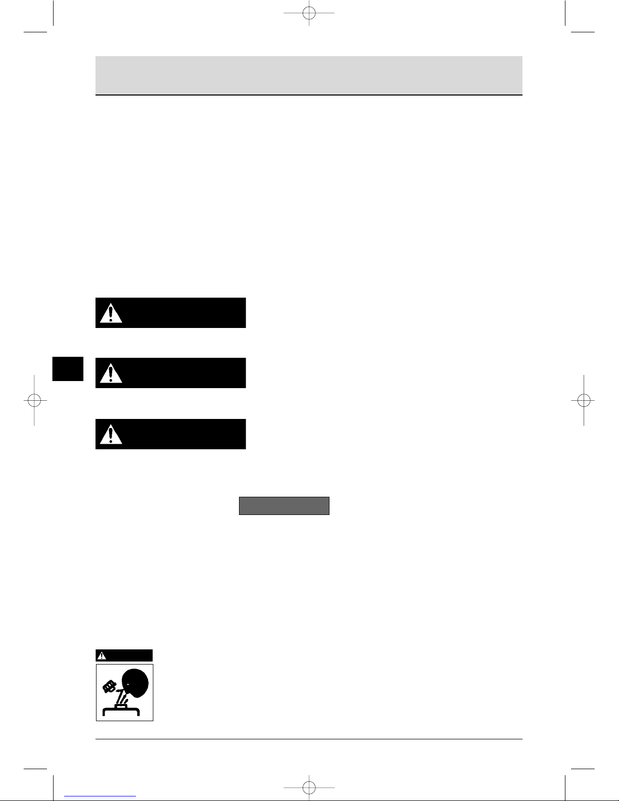
1.3 WARNING LABELS
To insure safe operation, warning device
labels have been attached. Their location is
shown below and they should always be
visible. Please replace if damaged or lost.
1. For your safety
7
GB
Product Safety Labels, Parts Code Numbers
128377-07350
128296-07260
128296-07300
196630-12980
JH-Turbo-Engels1a 30-06-2002 13:17 Pagina 7

2.1 USE, DRIVING SYSTEM, ETC.
This is a light, compact diesel engine for use in pleasure boats. The engine is equipped with
a turbocharger and intercooler which insures maximum output while preserving lightness
and compact size. (The 4JH3-TE series is equipped with the turbocharger only.)
Power output for this group of engines increases progressively from 4JH3-TE, 4JH3-HTE to
4JH3-DTE.
The inboard series is equipped with a marine gear connecting the output shaft with the
propeller shaft for operation.
The different types of marine gears used for each series are shown below.
In order to obtain full performance from your engine, it is imperative that you check the size
and structure of the hull and use a propeller of the appropriate size.
The engine must be installed correctly with safe cooling water and exhaust piping and
electrical wiring. The PTO work should be easy to use for onboard equipment.
The laws of some countries may require hull and engine inspections, depending on the use,
size and cruising area of the boat.
The installation, fitting and surveying of this engine all require specialized knowledge and
engineering skills. Consult Yanmar’s local subsidiary in your region or your distributor or
dealer.
Consult your Yanmar dealer or distributor when selecting optional parts. Optional parts
selections should take into account operational and surrounding conditions.
This Operation Manual explains the basic points for standard operation. Variations are
explained under the specially marked sections.
2. Product explanation
8
GB
4JH3-TE 4JH3-HTE 4JH3-DTE
Marine Gear Series Series Series
KBW21 Clutch 4JH3-TE 4JH3-HTE N/A
KM4A Clutch 4JH3-TBE 4JH3-HTBE N/A
KMH4A Clutch 4JH3-THE 4JH3-HTHE 4JH3-DTHE
Mechanical wet cone clutch
Input/output special parallel drive
Mechanical wet cone clutch
7° Down angle drive
Hydraulic wet multiple disk clutch
8° Down angle drive
JH-Turbo-Engels1a 30-06-2002 13:17 Pagina 8

This Operation Manual explains the basic points for standard operation. Variations are
explained under the letter emblems for easy reference.
Model : Explanation of indicated model only.
Option : Explanation of optional parts.
Customer : Explanation of use of parts from other boat manufacturers.
In sections without letter emblems, the explanation applies to all models.
Explanation for driving devices, propellers, etc. and optional parts are not included,
and special attention should be paid to the explanations and safety precautions in the
operation manuals provided by the boat and equipment manufacturers.
2. Product explanation
9
GB
JH-Turbo-Engels1a 30-06-2002 13:17 Pagina 9
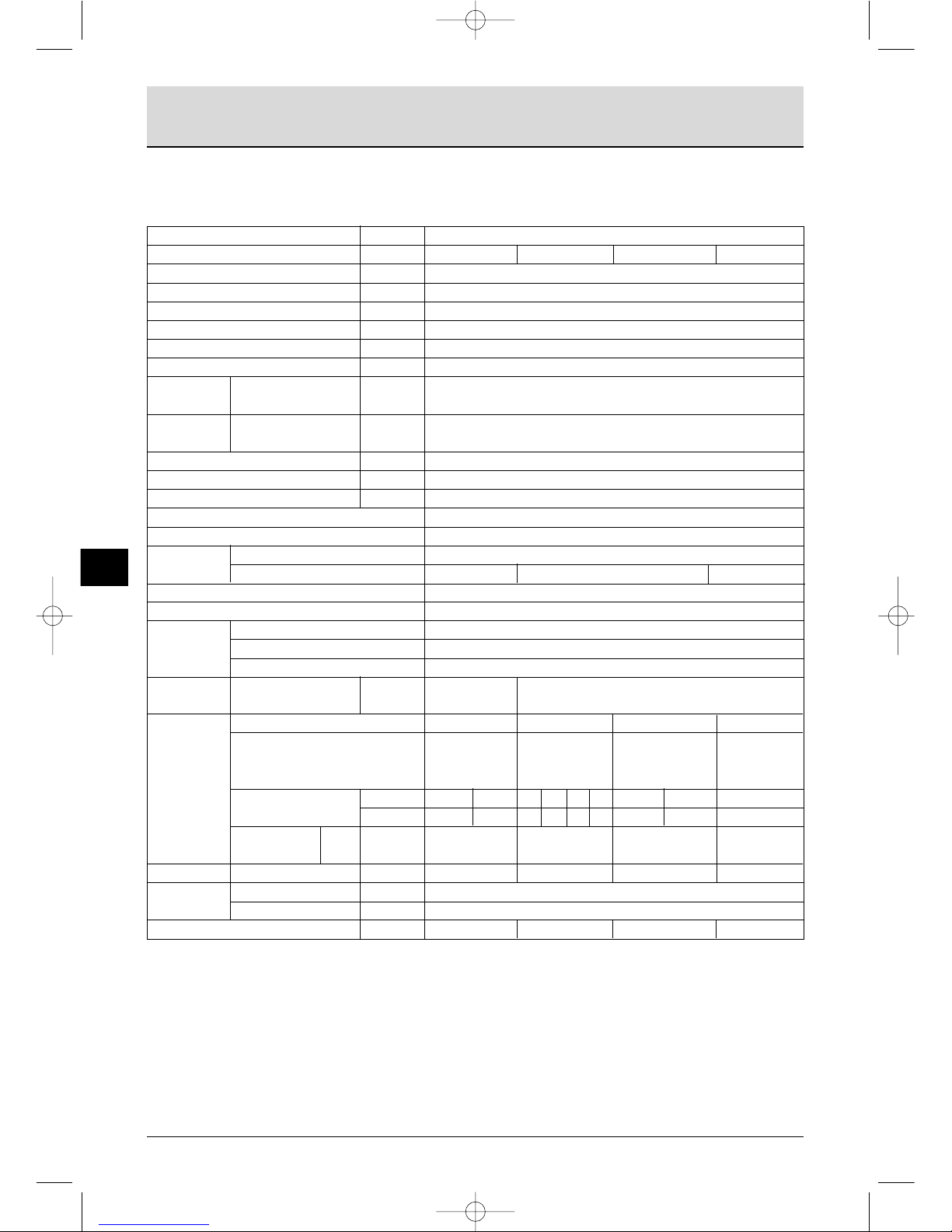
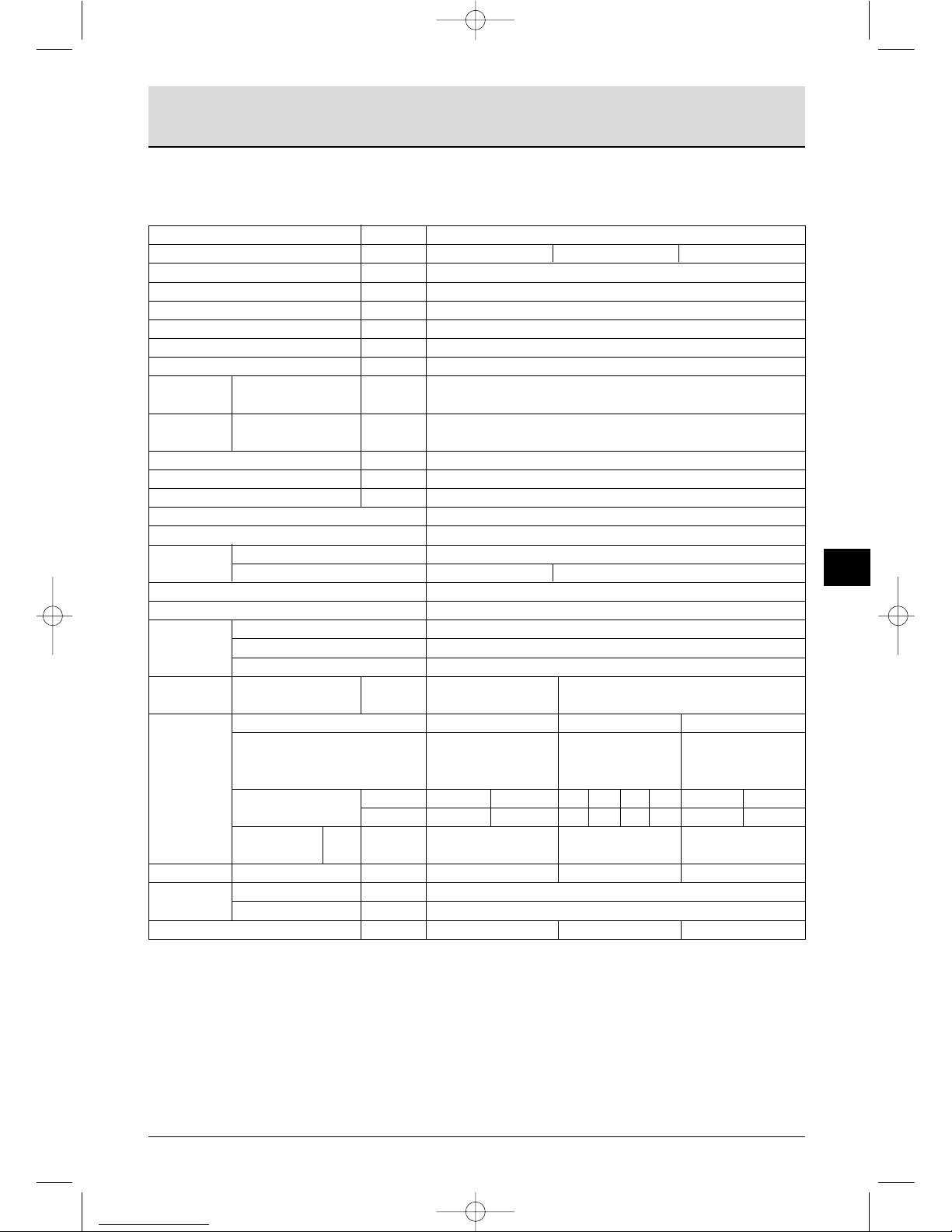
2.2 Engine Specifications
2.2.1
2. Product explanation
10
GB
Item Unit Model
Engine Model -- 4JH3-TE 4JH3-TBE 4JH3-THE 4JH3-TCE
Type --
Combustion system --
Number of cylinders -- 4
Bore x stroke mm 84 x 90
Displacement 1.995
Aspiration system -- turbocharger
Continuous Output/crankshaft kW/rpm 50.7 / 3700
rating output speed (hp/rpm) (69 / 3700)
One hour Output/crankshaft kW/rpm 55.2 / 3800
rating output
speed (hp/rpm) (75 / 3800)
Low idling rpm 700 ± 25
Fuel injection timing (b.T.D.C.) º 12 ± 1
Fuel injection pressure kg/cm
2
220 ± 5
Main power take off
Front power take off
Direction of
Crankshaft
rotation
Propeller shaft (ahead)
Cooling system
Lubrication system
Type
Starting
Starting motor
system
AC generator
Engine
Lubricating oil standard 6.3 7.05
capacity (rake angle) unit (7°) (0°)
Model
KWB21 KM4A KMH4A
SD40-4TSail
Drive
Type
Marine gear
Reduction ratio
Forward
2.17 2.62 1.47 2.14 2.63 3.30 2.04 2.45 2.32
Reverse
3.06 3.06 1.47 2.14 2.63 3.30 2.04 2.45 2.32
Lubricating oil
capacity
Total 1.2 1.3 2.0 1.8
Dimensions L x W x H mm 906 x 560 x 635 888 x 565 x 635 938 x 565 x 635
1086 x 565 x 433
Cooling water
Fresh water tank 6.0
capacity
Subtank 0.8
Engine weight with marine gear kg 249 247 250 260
vertical 4-cycle water cooled diesel engine
direct injection
at flywheel side
at crankshaft V-pulley side
Counter-clockwise viewed from stern
fresh water cooler with heat exchanger
complete enclosed forced lubrication
electric
DC 12V, 1.4 kW
12V, 55A (12V, 80A optional)
clockwise bi-rotation
mechanical wet
multiple disk clutch
Input/output eccen-
tric parallel drive
mechanical wet
cone clutch 7°
down angle drive
hydraulic wet
multiple disk clutch
8° down angle drive
Cone clutch
1.) Rating condition: ISO 3046-1 and ISO 8665 2.) 1hp=0.7355 kW
counter-clockwise or
clockwise viewed from
stem
JH-Turbo-Engels1a 30-06-2002 13:17 Pagina 10
2. Product explanation
GB
11
2.2.2
Item Unit Model
Engine Model -- 4JH3-HTE 4JH3-HTBE 4JH3-HTHE
Type --
Combustion system --
Number of cylinders -- 4
Bore x stroke mm 84 x 90
Displacement 1.995
Aspiration system -- turbocharger, intercooler
Continuous Output/crankshaft kW/rpm 67.7 / 3700
rating output speed (hp/rpm) (92 / 3700)
One hour Output/crankshaft kW/rpm 73.6 / 3800
rating output
speed (hp/rpm) (100 / 3800)
Low idling rpm 700 ± 25
Fuel injection timing (b.T.D.C.) º 12 ± 1
Fuel injection pressure kg/cm
2
220 ± 5
Main power take off
Front power take off
Direction of
Crankshaft
rotation
Propeller shaft (ahead)
Cooling system
Lubrication system
Type
Starting
Starting motor
system
AC generator
Engine
Lubricating oil standard 6.3 7.5
capacity (rake angle) unit (7°) (0°)
Model KWB21 KM4A KMH4A
Type
Marine gear
Reduction ratio
Forward 2.17 2.62 1.47 2.14 2.63 3.30 2.04 2.45
Reverse 3.06 3.06 1.47 2.14 2.63 3.30 2.04 2.45
Lubricating oil
capacity
Total 1.2 1.3 2.0
Dimensions L x W x H mm 906 x 576 x 660 888 x 581 x 660 938 x 581 x 660
Cooling water
Fresh water tank 7.2
capacity
Subtank 0.8
Engine weight with marine gear kg 258 256 259
vertical 4-cycle water cooled diesel engine
direct injection
at flywheel side
at crankshaft V-pulley side
Counter-clockwise viewed from stern
fresh water cooler with heat exchanger
complete enclosed forced lubrication
electric
DC 12V, 1.4 kW
12V, 55A (12V, 80A optional)
clockwise bi-rotation
mechanical wet multiple
disk clutch Input/output
eccentric parallel drive
mechanical wet cone
clutch 7° down angle
drive
hydraulic wet multiple
disk clutch 8° down
angle drive
1.) Rating condition: ISO 3046-1 and ISO 8665 2.) 1hp=0.7355 kW
JH-Turbo-Engels1a 30-06-2002 13:17 Pagina 11

2. Product explanation
12
GB
2.2.3
Item Unit Model
Engine Model -- 4JH3-DTHE
Type --
Combustion system --
Number of cylinders -- 4
Bore x stroke mm 84 x 90
Displacement 1.995
Aspiration system -- turbocharger, intercooler
Continuous Output/crankshaft kW/rpm 85.3 / 3700
rating output speed (hp/rpm) (116.0 / 3700)
One hour Output/crankshaft kW/rpm 91.9 / 3800
rating output
speed (hp/rpm) (125 / 3800)
Low idling rpm 700 ± 25
Fuel injection timing (b.T.D.C.) º 12 ± 1
Fuel injection pressure kg/cm
2
220 ± 5
Main power take off
Front power take off
Direction of
Crankshaft
rotation
Propeller shaft (ahead)
Cooling system
Lubrication system
Type
Starting
Starting motor
system
AC generator
Engine
Lubricating oil standard 7.5
capacity (rake angle) unit (0°)
Model KMH4A
Type
Marine gear
Reduction ratio
Forward 2.04 2.45
Reverse 2.04 2.45
Lubricating oil
capacity
Total 2.0
Dimensions L x W x H mm 938 x 581 x 660
Cooling water
Fresh water tank 7.2
capacity
Subtank 0.8
Engine weight with marine gear kg 260
vertical 4-cycle water cooled diesel engine
direct injection
at flywheel side
at crankshaft V-pulley side
clockwise viewed from stern
fresh water cooler with heat exchanger
complete enclosed forced lubrication
electric
DC 12V, 1.4 kW
12V, 55A (12V, 80A optional)
bi-rotation
hydraulic wet multiple disk clutch 8° down angle drive
1.) Rating condition: ISO 3046-1 and ISO 8665 2.) 1hp=0.7355 kW
JH-Turbo-Engels1a 30-06-2002 13:17 Pagina 12
2. Product explanation
13
GB
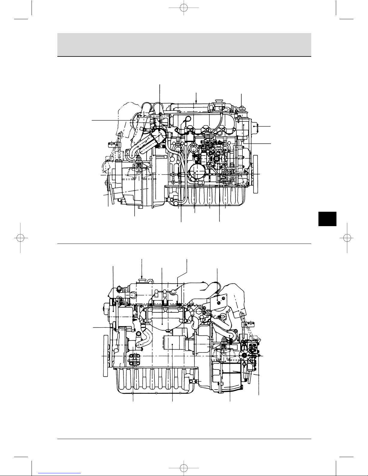
Non Operation Side
2.3 Names of Parts Operation Side
Oil cooler (engine)
Fuel oil filter
Name plate
Fuel priming pump
Fresh water
pump
Trawling lever
(option)
Dipstick
(clutch)
Dipstick
(engine)
Lube oil filter
Fuel injection pump
Intake air
silencer
Filler cap
Fresh water cooler
Alternator
* Intercooler
Turbocharger
V-belt
Clutch lever
Seawater pump
Starter
Oil cooler(clutch)
NOTE:
The 4JH3-DTHE engine (with KMH4A clutch) is used as the example for the above diagram.
The 4JH3-TE Series is not equipped with an intercooler (indicated by * in the diagram).
JH-Turbo-Engels1a 30-06-2002 13:17 Pagina 13
2. Product explanation
14
GB
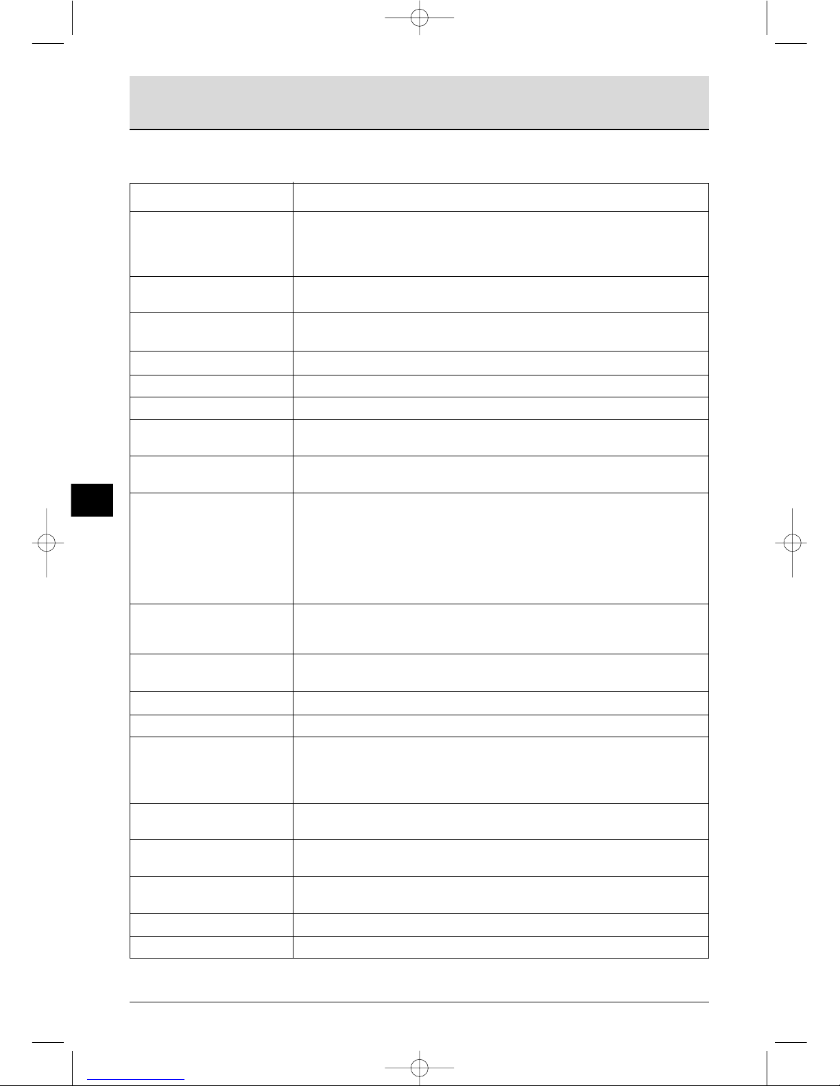
Name of part Function
Fuel filter Removes dust and water from fuel. The internal element (filter) should be
changed periodically.
A water separator is on the bottom of the filter and should be drained
periodically.
Fuel priming pump This is a manual fuel pump. Moving the knob on the top of the fuel filter
feeds the fuel. The pump is also used to bleed air from the fuel system.
Fuel feed pump This is a mechanical pump used to feed fuel to the fuel injection pump. It is
built into the fuel injection pump.
Filler port (engine) Filler port for engine lube oil.
Filler port (marine gear) Filler port for marine gear lube oil.
Dipstick (Lube oil) Gauge stick for determinining the level of the engine and marine gear oil.
Lube oil filter Filters fine metal fragments and carbon from the lube oil.
Filtered lube oil is distributed to the engine’s moving parts.
Cooling System Seawater passes through the heat exchanger cooling the fresh water,
which in turn cools the engine.
Fresh water cooling
Fresh water pump There are two cooling systems: fresh water and seawater.
The fresh water pump is run by the alternator and the V-belt.
Fresh water cooling The fresh water in the fresh water cooler is fed to the engine by the fresh
water pump. The cooling fresh water returns to the engine after it is cooled
with seawater in the fresh water cooler.
Filler cap The filler cap on the cooling water tank covers the water supply port. The
cap has a pressure regulating valve. When the cooling water temp. rises,
the pressure rises inside the fresh water cooler.
Subtank The pressure regulating valve releases vapor and hot water overflow to the
subtank.
Oil cooler (engine oil) This heat exchanger cools high temp. engine oil with seawater.
Oil cooler (clutch oil) This heat exchanger cools high temp. clutch oil with seawater.
Turbocharger With the pressurized intake air feeding device the exhaust gas turbine is
rotated by exhaust gas, and the power is used to rotate the blower.
This pressurizes the intake air for sending to the cylinder gives high power
output.
Intercooler This heat exchanger cools the pressurized intake air from the
turbocharger with seawater and further compresses it.
Intake air silencer This is the air intake silencer. The silencer guards against dirt in the air and
reduces the noise of air intake.
Name plate Name plates are provided on the engine and the marine gear and have the
model, serial number and other data.
Starter Starter motor for the engine. Powered by the battery.
Alternator Rotates by belt drive, generates electricity and charges the battery.
2.4 Major Servicing Parts
JH-Turbo-Engels1a 30-06-2002 13:17 Pagina 14

2.5 Control Equipment
2.5.1 Control Panel
The instrument panel is located in the control room. The following instruments enable you to
start/stop the engine and to monitor its condition during operation.
B type New B type
C type New C type
D type New D type
15
GB
2. Product explanation
Tachometre
Hour metre
C.W. temp. metre
L.O. temp. metre
Boost pressure metre
Alarm lamps
Starter switch
Stop button switch
Buzzer stop switch
Alarm buzzer
Illumination switch
Digital clock
Fuse
JH-Turbo-Engels1a 30-06-2002 13:18 Pagina 15

(1) Metres
The following metres are located in the
upper centre part of the instrument panel.
• B/C/D and New B/C/D type panels use
analog electric systems and have a
pointer indicator.
Turn the panel light switch ON for easy
viewing.
• Tachometre
The engine's rotation speed is indicated.
Load and engine rotation can be
monitored.
• Hour metre
The number of hours of operation is
indicated, and can be used as a guide for
periodic maintenance checks.
• Cooling Water Temperature Metre
Option Instrument Panel C.D.
The cooling water temperature is
indicated. Enables monitoring of the
cooling condition of the engine.
• Lube Oil Pressure Metre
Option Instrument Panel C.D.
The engine oil pressure is indicated.
Enables monitoring of the condition of
the engine's lube oil.
1 BATTERY CHARGE
When the charge is abnormal, the
lamp will come on. When charging
begins the lamp will go off. (Alarm
buzzer will not sound when the lamp comes
on.)
2 C. WATER TEMP
When the temperature of the
cooling fresh water exceeds the
maximum (95°C or higher), the lamp
will light. Continuing operation at
temperatures exceeding the maximum will
result in damage and seizure. Check the
load and the fresh water cooling system for
any abnormalities.
3 LUB. OIL PRESS.
When the lube oil pressure falls
below normal the oil pressure
sensor will register this and the lamp
will come on. Continuing operation with
2. Product explanation
16
GB
insufficient oil will result in damage and
seizure. Check the oil level.
4 FUEL FILTER
When the drain inside the water
separator in the fuel filter becomes
excessive, the sensor will cause the
lamp to come on. Clean out the drain in the
water separator. If operation is continued
without cleaning, it will become impossible
to feed fuel to the engine or damage and
seizure of the fuel injection pump will result.
5 EXHAUST Option
When the amount of cooling
seawater being discharged
becomes too small, the sensor will
activate the lamp. Continuing operation
under this condition will result in damage
and seizure. Check for clogging in the
seawater cooling system and damaged
parts.
JH-Turbo-Engels1a 30-06-2002 13:18 Pagina 16
 Loading...