

Yanmar 4BY2, 6BY2 Operation Manuals
BY
series
OPERATION MANUAL
4BY2
6BY2
P/N: 0ABY0-G00200
MARINE
ENGINES
Disclaimers:
All information, illustrations and specifications in this manual are based on the latest
information available at the time of publishing. The illustrations used in this manual are
intended as representative reference views only. Moreover, because of our continuous
product improvement policy, we may modify information, illustrations and / or specifications
to explain and / or exemplify a product, service or maintenance improvement. We reserve
the right to make any change at any time without notice. Yanmar and are
registered trademarks of Yanmar Co., Ltd. in Japan, the United States and / or other
countries.
All Rights Reserved:
No part of this publication may be reproduced or used in any form by any means - graphic,
electronic, or mechanical, including photocopying, recording, taping, or information storage
and retrieval systems - without the written permission of Yanmar Marine International.
© 2008 Yanmar Marine International
1108
ii BY Series Operation Manual
© 2008 Yanmar Marine International

TABLE OF
CONTENTS
Page
Introduction......................................................................1
Record of Ownership......................................................2
Safety...............................................................................3
Safety Precautions.........................................................4
General Information .................................................4
Before You Operate .................................................4
During Operation and Maintenance .............................4
Safety Decals................................................................8
Product Overview..............................................................9
Yanmar BY-Series Features and Applications......................9
New Engine Break In.............................................. 10
Component Identification...............................................11
Left Side (as viewed from flywheel) - 4BY2.................. 11
Right Side (as viewed from flywheel) - 4BY2................ 11
Top View - 4BY2 ................................................... 12
Left Side - 6BY2 .................................................... 12
Right Side - 6BY2 .................................................. 13
Top View - 6BY2 ................................................... 13
Location of Nameplates.................................................14
Function of Major Components........................................16
Fuses and Relays.........................................................18
Engine Cover..............................................................19
Before You Operate..........................................................21
Diesel Fuel..................................................................22
Diesel Fuel Specifications ....................................... 22
Filling the Fuel Tank ............................................... 24
Bleeding the Fuel System........................................ 24
Engine Oil...................................................................25
Engine Oil Specifications......................................... 25
Acceptable Engine Oil ............................................ 26
Checking Engine Oil............................................... 29
BY Series Operation Manual iii
© 2008 Yanmar Marine International

TABLE OF CONTENTS
Adding Engine Oil.................................................. 29
Marine Gear or Stern Drive Oil.........................................30
Power Steering Fluid Specifications..................................30
Checking Power Steering Fluid Level......................... 30
Engine Coolant............................................................31
Acceptable Engine Coolant...................................... 31
Engine Operation.............................................................33
Starting the Engine.......................................................34
Starting at Low Temperatures .................................. 35
Shutting Down the Engine..............................................35
Emergency Shut Down ........................................... 35
Checking the Engine After Operation................................36
Periodic Maintenance.......................................................37
Safety Precautions.......................................................37
Precautions.................................................................39
The Importance of Periodic Maintenance .................... 39
Performing Periodic Maintenance ............................. 39
The Importance of Daily Checks ............................... 39
Keep a Log of Engine Hours and Daily Checks............. 39
Yanmar Replacement Parts ..................................... 39
Tools Required ..................................................... 39
Ask Your Authorized Yanmar Marine Dealer or
Distributor For Help................................................ 39
Required EPA Maintenance..................................... 39
EPA Requirements.......................................................40
Conditions to Ensure Compliance with EPA Emission
Standards............................................................ 40
Inspection and Maintenance .................................... 40
Tightening Fasteners.............................................. 40
Periodic Maintenance Schedule......................................42
Inspection and Maintenance of EPA Emission-Related
Parts................................................................... 46
Daily Checks...............................................................46
Visual Checks....................................................... 46
Checking Diesel Fuel, Engine Oil and Engine Coolant
Levels................................................................. 47
Checking the Battery Electrolyte Level ....................... 47
Checking the Alarm Indicators.................................. 47
Preparing Fuel, Oil and Coolant in Reserve ................. 47
Checking Power Steering Fluid................................. 47
Draining the Fuel / Water Separator ........................... 47
Periodic Maintenance Procedures....................................48
After Initial 50 Hours of Operation.............................. 48
Every 50 Hours of Operation .................................... 49
Every 250 Hours of Operation .................................. 50
Every 500 Hours of Operation .................................. 55
iv BY Series Operation Manual
© 2008 Yanmar Marine International

TABLE OF CONTENTS
Every 1000 Hours of Operation................................. 56
Every 2000 Hours of Operation................................. 57
Troubleshooting..............................................................59
Troubleshooting Information........................................... 59
Troubleshooting Chart...................................................60
Starting Trouble .................................................... 60
Exhaust Color....................................................... 61
Vibration - Drive Disengaged.................................... 61
Vibration - Drive Engaged........................................ 62
Engine Knocks...................................................... 62
Low Power Output ................................................. 62
Engine Overheat ................................................... 63
Engine Runs Cold.................................................. 63
Coolant Loss ........................................................ 63
Diagnostic Trouble Codes..............................................64
Diagnostic Trouble Code Table ................................ 65
Long-Term Storage..........................................................69
Prepare Engine for Long-Term Storage.............................69
Draining the Seawater Cooling System....................... 70
Specifications..................................................................71
Engine Specifications....................................................71
EPA Warranty USA Only....................................................75
Yanmar Co., Ltd. Limited Emission Control System Warranty
- USA Only..................................................................75
Your Warranty Rights and Obligations: ....................... 75
Warranty Period: ................................................... 76
Warranty Coverage:............................................... 76
Exclusions: .......................................................... 76
Owner’s Responsibility: .......................................... 76
Customer Assistance: ............................................ 77
Maintenance Log................................................... 78
BY Series Operation Manual v
© 2008 Yanmar Marine International

TABLE OF CONTENTS
This Page Intentionally Left Blank
vi BY Series Operation Manual
© 2008 Yanmar Marine International

INTRODUCTION
Welcome to the world of Yanmar Marine!
Yanmar Marine offers engines, drive
systems and accessories for all types of
boats, from runabouts to sailboats, and from
cruisers to mega yachts. In marine leisure
boating, the worldwide reputation of Yanmar
Marine is second to none. We design our
engines to respect nature. This means
quieter engines, with minimal vibrations,
cleaner than ever. All of our engines
designed after 1996 meet most of the
present and future emission regulations,
such as BSO II, SAV, EPA II, IMO and RCD.
To help you enjoy your Yanmar BY2 engine
for many years to come, please follow these
recommendations:
• Read and understand this Operation
Manual before you operate the machine to
ensure that you follow safe operating
practices and maintenance procedures.
• Keep this Operation Manual in a
convenient place for easy access.
• If this Operation Manual is lost or
damaged, order a new one from your
authorized Yanmar marine dealer or
distributor.
• Make sure this manual is transferred to
subsequent owners. This manual should
be considered a permanent part of the
engine and remain with it.
• Constant efforts are made to improve the
quality and performance of Yanmar
products, so some details included in this
Operation Manual may differ slightly from
your engine. If you have any questions
about these differences, please contact
your authorized Yanmar marine dealer or
distributor.
• The specifications and components
(instrument panel, fuel tank, etc.)
described in this manual may differ from
ones installed on your vessel. Please refer
to the manual provided by the
manufacturer of these components.
• Refer to the Yanmar Limited Warranty
Handbook for a complete warranty
description.
BY Series Operation Manual 1
© 2008 Yanmar Marine International

INTRODUCTION
RECORD OF OWNERSHIP
Take a few moments to record the information you need when you contact Yanmar for
service, parts or literature.
Engine Model:
Engine Serial No.:
Date Purchased:
Dealer:
Dealer Phone:
2 BY Series Operation Manual
© 2008 Yanmar Marine International
SAFETY
!
Yanmar considers safety of great
importance and recommends that anyone
that comes into close contact with its
products, such as those that install, operate,
maintain or service Yanmar products,
exercise care, common sense and comply
with the safety information in this manual
and on the machine’s safety labels. Keep
the labels from becoming dirty or torn and
replace them if they are lost or damaged.
Also, if you need to replace a part that has a
label attached to it, make sure you order the
new part and label at the same time.
This safety alert symbol appears
with most safety statements. It
means attention, become alert,
your safety is involved! Please
read and abide by the message
that follows the safety alert
symbol.
DANGER
Indicates an hazardous situation which, if
not avoided, will result in death or serious
injury.
WARNING
Indicates a hazardous situation which, if not
avoided, could result in death or serious
injury.
CAUTION
Indicates a hazardous situation which, if not
avoided, could result in minor or moderate
injury.
NOTICE
Indicates a situation which can cause
damage to the engine, personal property
and / or the environment or cause the
equipment to operate improperly.
BY Series Operation Manual 3
© 2008 Yanmar Marine International
SAFETY
SAFETY PRECAUTIONS
General Information
There is no substitute for common sense
and careful practices. Improper practices or
carelessness can cause burns, cuts,
mutilation, asphyxiation, other bodily injury
or death. This information contains general
safety precautions and guidelines that must
be followed to reduce risk to personal safety.
Special safety precautions are listed in
specific procedures. Read and understand
all of the safety precautions before operation
or performing repairs or maintenance.
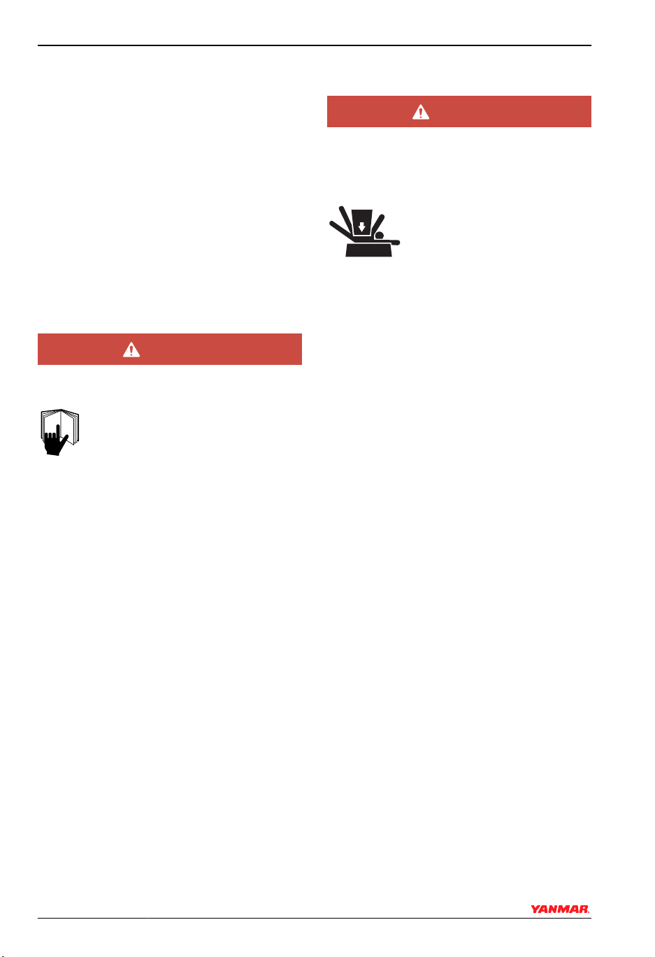
Before You Operate
DANGER
The safety message that follows has
DANGER level hazards.
NEVER permit anyone to install or
operate the engine without proper
training.
• Read and understand this Operation
Manual before you operate or service the
engine to ensure that you follow safe
operating practices and maintenance
procedures.
• Safety signs and labels are additional
reminders for safe operating and
maintenance techniques.
• See your authorized Yanmar Marine
dealer or distributor for additional training.
During Operation and Maintenance
DANGER
The safety message that follows has
DANGER level hazards.
Crush Hazard
NEVER stand under hoisted
engine. If the hoist
mechanism fails, the engine
will fall on you.
4 BY Series Operation Manual
© 2008 Yanmar Marine International
SAFETY
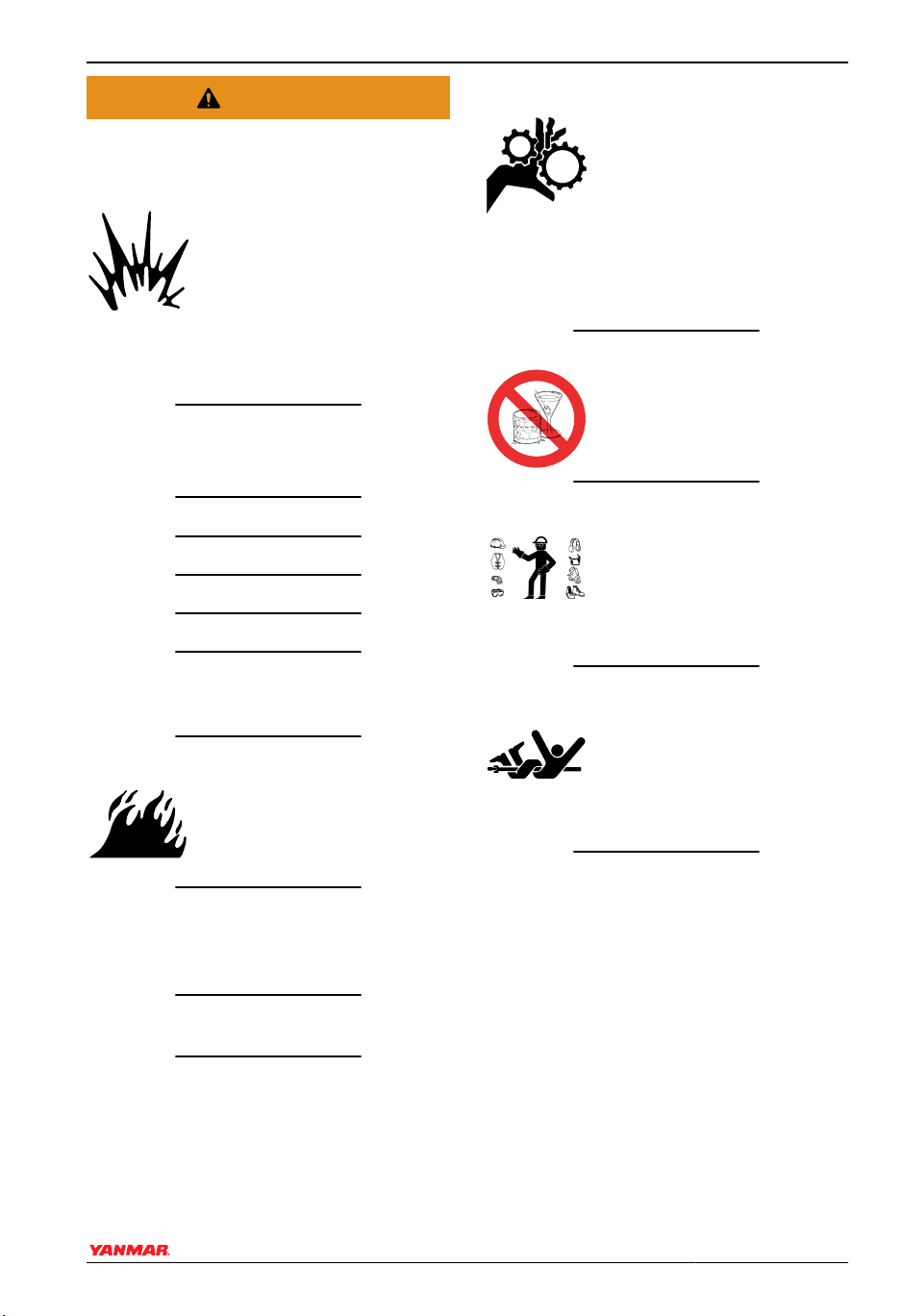
WARNING
The safety messages that follow have
WARNING level hazards.
Explosion Hazard
While the engine is running or
the battery is charging,
hydrogen gas is being
produced and can be easily
ignited. Keep the area around
the battery well-ventilated and keep sparks,
open flames and any other form of ignition
out of the area.
Fire and Explosion Hazard
Diesel fuel is flammable and explosive
under certain conditions.
NEVER use a shop rag to catch the fuel.
Wipe up all spills immediately.
NEVER refuel with the engine running.
NEVER use diesel fuel as a cleaning agent.
Store any containers containing fuel in a
well-ventilated area, away from any
combustibles or sources of ignition.
Fire Hazard
Undersized wiring systems
can cause an electrical fire.
Sever Hazard
Rotating parts can cause
severe injury or death.
NEVER wear jewelry,
unbuttoned cuffs, ties or loose
fitting clothing and ALWAYS
tie long hair back when working near
moving / rotating parts such as the flywheel
or PTO shaft. Keep hands, feet and tools
away from all moving parts.
Alcohol and Drug Hazard
NEVER operate the engine
while under the influence of
alcohol or drugs or feeling ill.
Exposure Hazard
ALWAYS wear personal
protective equipment
including appropriate
clothing, gloves, work shoes,
eye and hearing protection as
required by the task at hand.
Entanglement Hazard
NEVER leave the key in the
key switch when you are
servicing the engine.
Someone may accidentally
start the engine and not
realize you are servicing it.
Store any containers containing fuel or other
flammable products in a well-ventilated
area, away from any combustibles or source
of ignition.
Store any equipment in a designated area
away from moving parts.
NEVER use the engine compartment for
storage.
BY Series Operation Manual 5
© 2008 Yanmar Marine International
NEVER operate the engine while wearing a
headset to listen to music or radio because
it will be difficult to hear the warning signals.

SAFETY
WARNING
Piercing Hazard
Avoid skin contact with highpressure diesel fuel spray
caused by a fuel system leak
such as a broken fuel injection
line. High-pressure fuel can
penetrate your skin and result in serious
injury. If you are exposed to high-pressure
fuel spray, obtain prompt medical treatment.
NEVER check for a fuel leak with your
hands. ALWAYS use a piece of wood or
cardboard. Have your authorized Yanmar
Marine dealer or distributor repair the
damage.
Burn Hazard
Some of the engine surfaces
become very hot during
operation and shortly after
shutdown. Keep hands and
other body parts away from
hot engine surfaces.
Sudden Movement Hazard
ALWAYS stop the engine before beginning
service.
Exhaust Hazard
NEVER block windows, vents
or other means of ventilation if
the engine is operating in an
enclosed area. All internal
combustion engines create
carbon monoxide gas during operation and
special precautions are required to avoid
carbon monoxide poisoning.
CAUTION
The safety messages that follow have
CAUTION level hazards.
Poor Lighting Hazard
Ensure that the work area is adequately
illuminated. ALWAYS install wire cages on
portable safety lamps.
Tool Hazard
ALWAYS use tools appropriate for the task
at hand and use the correct size tool for
loosening or tightening machine parts.
Flying Object Hazard
ALWAYS wear eye protection when
servicing the engine or when using
compressed air or high-pressure water.
Dust, flying debris, compressed air,
pressurized water or steam may injure your
eyes.
Coolant Hazard
Wear eye protection and
rubber gloves when you
handle Long Life engine
coolant. If contact with the
eyes or skin should occur,
flush eyes and wash immediately with clean
water.
6 BY Series Operation Manual
© 2008 Yanmar Marine International

SAFETY
NOTICE
The safety messages that follow have
NOTICE level hazards.
It is important to perform daily checks as
listed in the Operation Manual. Periodic
maintenance prevents unexpected
downtime, reduces the number of accidents
due to poor engine performance and helps
extend the life of the engine.
See your authorized Yanmar Marine dealer
or distributor if you need to operate the
engine at high altitudes. At high altitudes the
engine will lose power, run rough and
produce exhaust gases that exceed the
design specifications.
ALWAYS be environmentally
responsible.
Follow the guidelines of the
EPA or other governmental
agencies for the proper
disposal of hazardous materials such as
engine oil, diesel fuel and engine coolant.
Consult the local authorities or reclamation
facility.
NEVER dispose of hazardous materials by
dumping them into a sewer, on the ground
or into ground water or waterways.
If a Yanmar Marine engine is installed at an
angle that exceeds the specifications stated
in the Yanmar Marine installation manuals,
engine oil may enter the combustion
chamber, causing excessive engine speed,
white exhaust smoke and serious engine
damage. This applies to engines that run
continuously or those that run for short
periods of time.
If you have an installation with two or three
engines and only one engine is operating,
the water pickup (thru-hull) of the nonrunning engine(s) should be closed. This will
prevent water from being forced past the
seawater pump and eventually finding its
way into the engine. The result of water
entering the engine could cause seizure or
other serious problems.
If you have an installation with two or three
engines, and only one engine is operating,
please note that if the propeller shaft thruhull (stuffing box) is lubricated by engine
water pressure and the engines are
interconnected, care must be taken that
water from the running engine does not
enter the exhaust of the non-running
engine(s). This water could cause seizure of
the non-running engine(s). See your
authorized Yanmar Marine dealer or
distributor for a complete explanation of this
condition.
If you have an installation with two or three
engines, and only one engine is operating,
it is important to limit the amount of throttle
applied to the running engine. If you observe
black smoke or movement of the throttle
does not increase engine rpm, you are
overloading the engine that is running.
Immediately throttle back to approximately
2/3 throttle or to a setting where the engine
performs normally. Failure to do so may
cause the running engine to overheat or
cause excess carbon buildup which may
shorten the engine’s life.
BY Series Operation Manual 7
© 2008 Yanmar Marine International

SAFETY
SAFETY DECALS
(1)
60˚
0.5 ton
When lifting the
engine, lift only
as shown in
diagram.
Weight: 0.5 ton
120650-07030
(9)
(2)
• Never remove
the cap while the
engine is still hot.
• Hot water may spurt
out and burn you.
120650-07040
(4)
(7)
(3)
ATTENTION
Before filling with
cooling water, close
the drain cock.
The drain cock is open
during shipment.
• NEVER pour the
engine oil across
the full line.
FULL
LOW
120650-07050
(1)
60˚
0.5 ton
When lifting the
engine, lift only
as shown in
diagram.
Weight: 0.5 ton
120650-07030
(6)
Replacement items
Lube oil
Lube oil filter element
Fuel filter element
Pre fuel filter element
Anitcorrosion zinc
(please refer to operation manual for details)
Air filter
After 250 hrs
or 1 year
120650-07070
(5)
Figure 1
1 – 120650-07030
2 – 120650-07040
3 – 120650-07050
4 – 120650-07060
6 – 120650-07080
7 – 120650-07090
8 – 120650-07100
9 – 120650-07121
5 – 120650-07070
8 BY Series Operation Manual
© 2008 Yanmar Marine International
(8)
0006620

PRODUCT OVERVIEW
YANMAR BY-SERIES FEATURES AND APPLICATIONS
The BY-series engines are in-line 4- and
6-cylinder direct injection diesel engines.
The engines are turbocharged and
equipped with a liquid cooling system.
These engines are designed for pleasure
craft use.
In order to obtain full performance from your
engine, it is imperative that you check the
size and structure of the hull and use a
propeller of the appropriate size. As new
boats are used, owners add additional
equipment and completely fill the fuel and
water tanks adding to the overall
displacement (weight) of the vessel. Extra
canvas enclosures, bottom paint, and
bottom fouling can add additional hull
resistance. It is recommended that a new
vessel be propped so the engine can
operate at 100 rpm above maximum rpm to
allow for some added weight and hull
resistance. Failure to do so can lead to
reduced vessel performance, increased
smoke levels and cause permanent
damage to your engine.
The engine must be installed correctly with
the seawater or cooling water piping,
exhaust gas piping and electrical wiring. Any
auxiliary equipment attached to the engine
should be easy to use and accessible for
service. To handle the drive equipment,
propulsion systems (including the propeller)
and other on-board equipment, be sure to
observe the instructions and cautions given
in the operation manuals supplied by the
shipyard and equipment manufacturers.
The laws of some countries may require hull
and engine inspections, depending on the
use, size and cruising area of the boat. The
installation, fitting and surveying of this
engine all require specialized knowledge
and engineering skills. See Yanmar's local
subsidiary in your region or your authorized
Yanmar marine dealer or distributor.
This engine is designed for pleasure boat
applications. The engine is designed to be
operated at: maximum throttle for less than
5% of its total operation time (30 minutes out
of every 10 hours). The engine should be
operated at cruising speed (3200 - 3300
rpm) for less than 90% of its total operation
time (9 hours out of every 10 hours).
BY Series Operation Manual 9
© 2008 Yanmar Marine International

PRODUCT OVERVIEW
New Engine Break In
• On the initial engine start-up, check for
proper engine oil pressure, diesel fuel
leaks, engine oil leaks, coolant leaks, and
for proper operation of the indicators and /
or gauges.
• During the first 50 hours of operation,
operate your new engine under a
substantial load at all times. For best
break-in results, operate the engine at
various speeds.
• During the first 50 hours of operation, try to
reduce unnecessary idling in Neutral.
• During the break-in period, carefully
observe the engine oil pressure and
engine temperature.
• During the break-in period, check the
engine oil and coolant levels frequently.
10 BY Series Operation Manual
© 2008 Yanmar Marine International

COMPONENT IDENTIFICATION
PRODUCT OVERVIEW
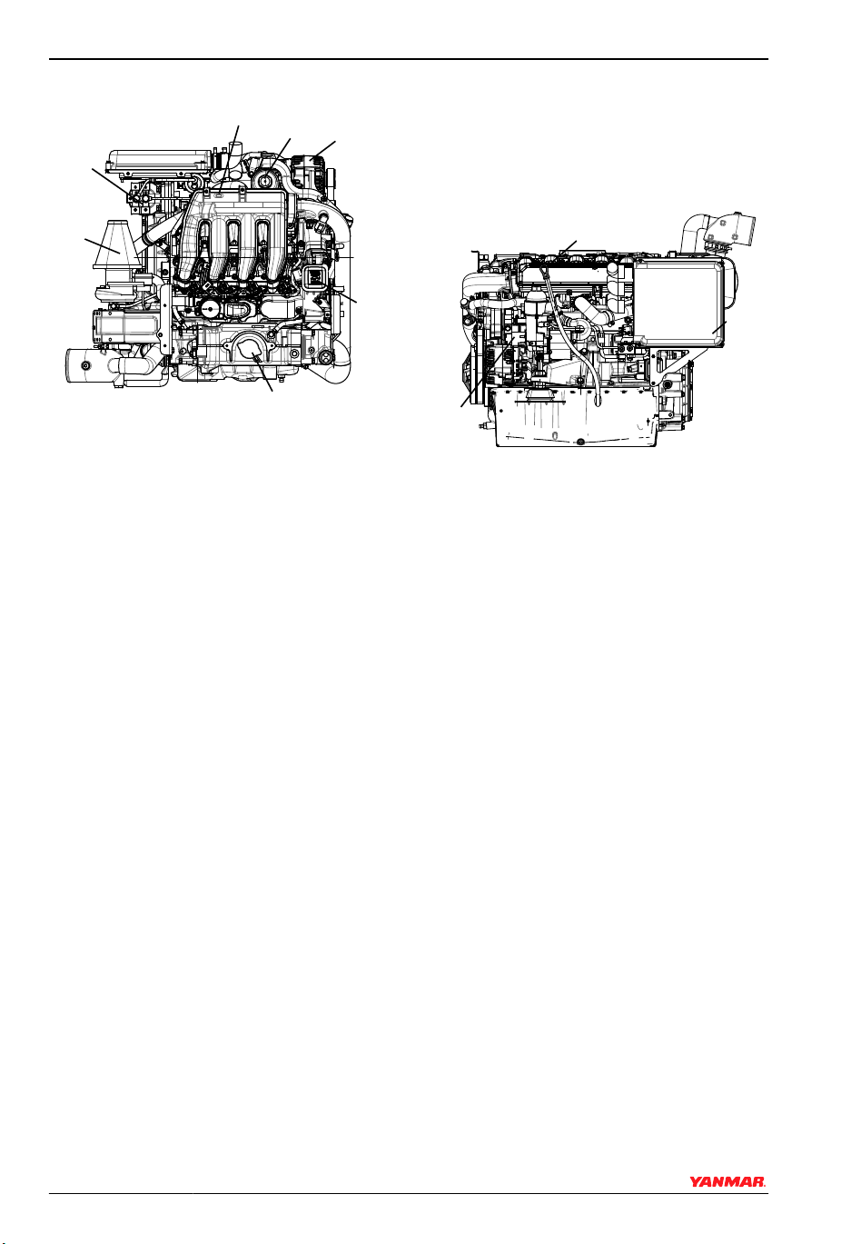
Figure 1, Figure 2 and Figure 3 illustrate a
typical version of a 4BY2 engine. Your
engine may have different equipment from
that illustrated.
Left Side (as viewed from flywheel) - 4BY2
(1)
(2)
(3)
Figure 1
1 – Engine Oil Dipstick
2 – E-Box Panel
3 – High Pressure Fuel Pump
0006557
Right Side (as viewed from flywheel) - 4BY2
(3)
(2)
(1)
(9)
Figure 2
1 – Zinc Anode
2 – Zinc Anode
3 – Exhaust / Water Mixing Elbow
4 – Coolant Drain Cock
5 – Heat Exchanger
6 – Seawater Pump
7 – Seawater Drain Cock
8 – Hydraulic Oil Cooler
9 – Coolant Drain Plug
(4)
(5)
(8)
0006559
(6)
(7)
BY Series Operation Manual 11
© 2008 Yanmar Marine International
PRODUCT OVERVIEW
Top View - 4BY2
(2)
(1)
(7)
Figure 3
1 – Fuel Fine Filter
2 – Intake Air Manifold
3 – Engine Oil Filter
4 – Power Steering Filler Port (if
equipped)
5 – Engine Oil Filler Port
6 – Coolant Filler Port
7 – Air Filter
Note: Yanmar supplies a water-separating
pre-filter for mounting by the installer. The
engine is equipped with an on-engine fine
filter (Figure 3, (1)).
(6)
(3)
0006560
(4)
(5)
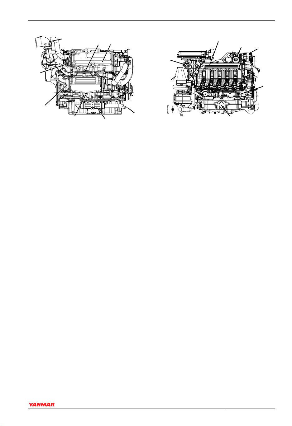
Figure 4, Figure 5 and Figure 6 illustrate a
typical version of a 6BY2 engine. Your
engine may have different equipment from
that illustrated.
Left Side - 6BY2
(1)
(2)
(3)
0006558
Figure 4
1 – Engine Oil Dipstick
2 – E-Box Panel
3 – High Pressure Fuel Pump
12 BY Series Operation Manual
© 2008 Yanmar Marine International
PRODUCT OVERVIEW
Right Side - 6BY2
(3)
(2)
(1)
(9)
Figure 5
1 – Zinc Anode
2 – Zinc Anode
3 – Exhaust / Water Mixing Elbow
4 – Coolant Drain Cock
5 – Heat Exchanger
6 – Seawater Pump
7 – Seawater Drain Cock
8 – Hydraulic Oil Cooler
9 – Coolant Drain Plug
(4)
(5)
(8)
(6)
(7)
0006561
Top View - 6BY2
(2)
(1)
(7)
Figure 6
1 – Fuel Fine Filter
2 – Intake Air Manifold
3 – Engine Oil Filter
4 – Power Steering Filler Port (if
equipped)
5 – Engine Oil Filler Port
6 – Coolant Filler Port
7 – Air Filter
Note: Yanmar supplies a water-separating
pre-filter for mounting by the installer. The
engine is equipped with an on-engine fine
filter (Figure 6, (1)).
(6)
(3)
(4)
(5)
0006562
BY Series Operation Manual 13
© 2008 Yanmar Marine International
PRODUCT OVERVIEW
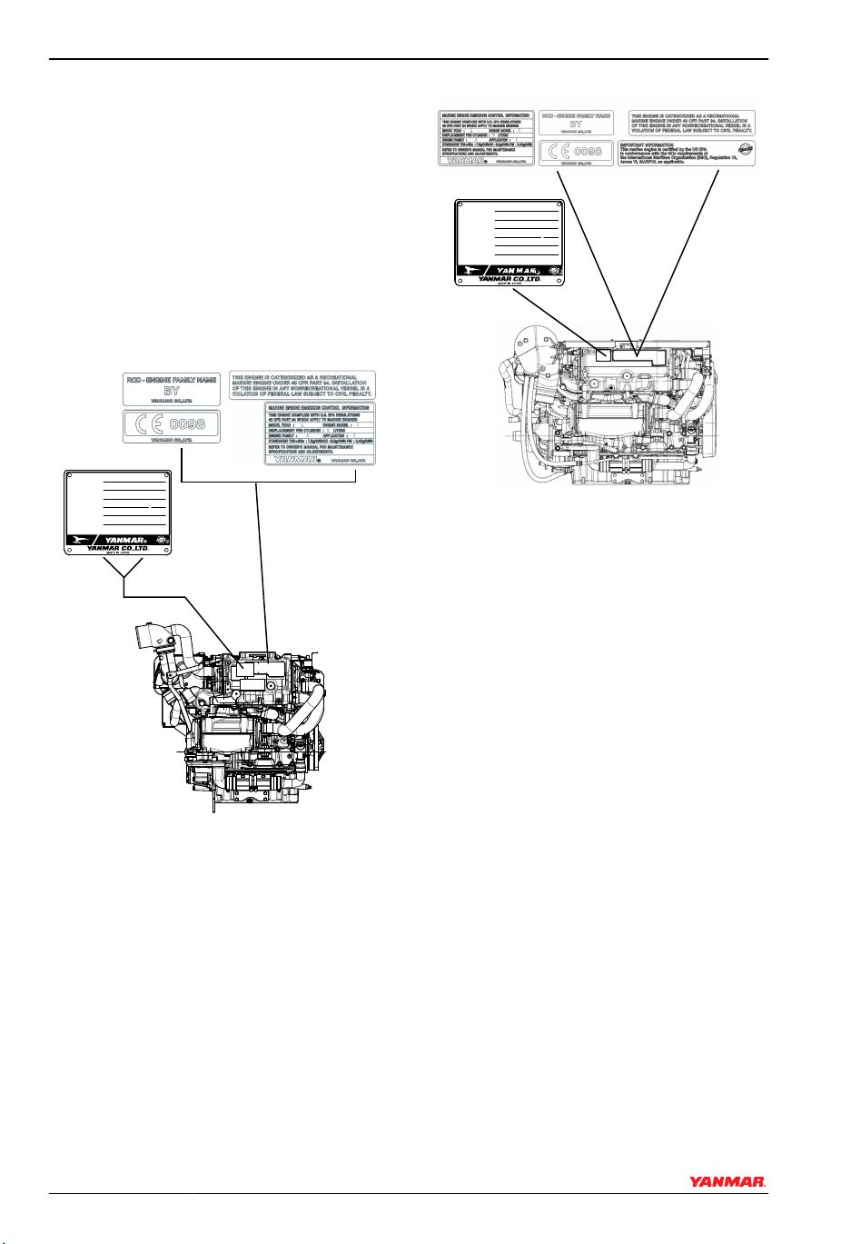
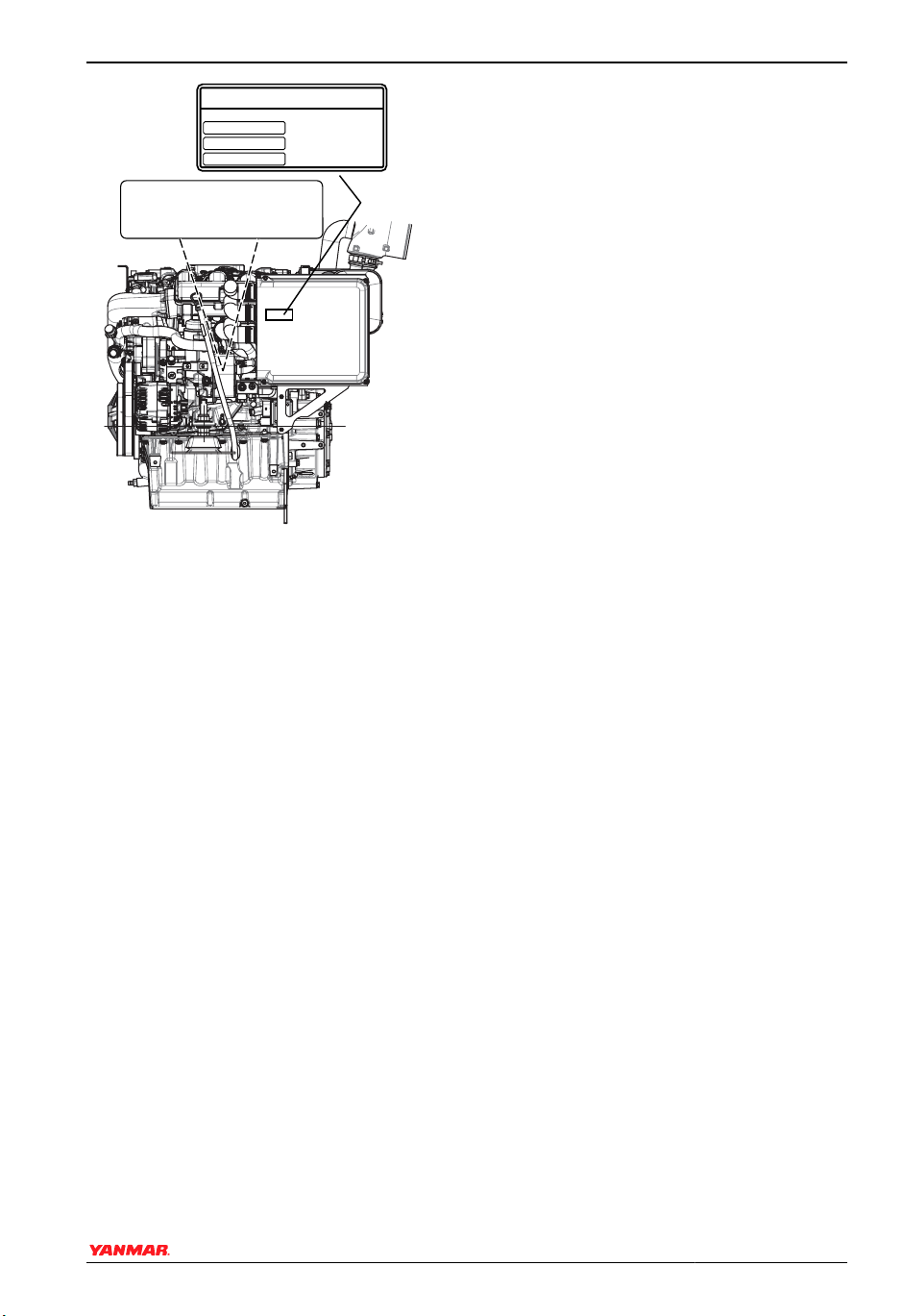
LOCATION OF NAMEPLATES
The engine data and drive information
nameplates on Yanmar BY2 series engines
are shown in Figure 7, Figure 8 and
Figure 9. Replace if damaged or lost.
The typical location of the engine name plate
is shown for Yanmar 4BY2 Series marine
engines (Figure 7) and 6BY2 engines
(Figure 8).
4BY2
Model
Gear Model
Continuous power kW
Speed of prop shaft
Fuel stop power kW
ENG.No.
-1
min
/
-1
min
-1
/
min
6BY2
Model
Gear Model
Continuous power kW
Speed of prop shaft
Fuel stop power kW
ENG.No.
-1
min
/
-1
min
-1
/
min
0006631
Figure 8
The engine block information is etched into
the cylinder block behind the engine oil
cooler near the end of the starting motor
(Figure 9).
0006563
Figure 7
14 BY Series Operation Manual
© 2008 Yanmar Marine International
MERCRUISER
DIVISION OF MERCURY MARINE
STILLWATER, OK, U.S.A.
SERIAL NUMBERS
ENGINE
TRANSOM
DRIVE
MODEL:
TRANSOM ASSEMBLY
AND STERN DRIVE
SERIAL NUMBER DECAL
STRIPS TO THE
RESPECTIVE BLANK
ON THIS DECAL.
PRODUCT OVERVIEW
4 B Y
1 0 8 5 N 0 7 5
1 1 0 0 7 8 2 4 9 5 1
N
Figure 9
0006567
BY Series Operation Manual 15
© 2008 Yanmar Marine International
PRODUCT OVERVIEW
FUNCTION OF MAJOR COMPONENTS
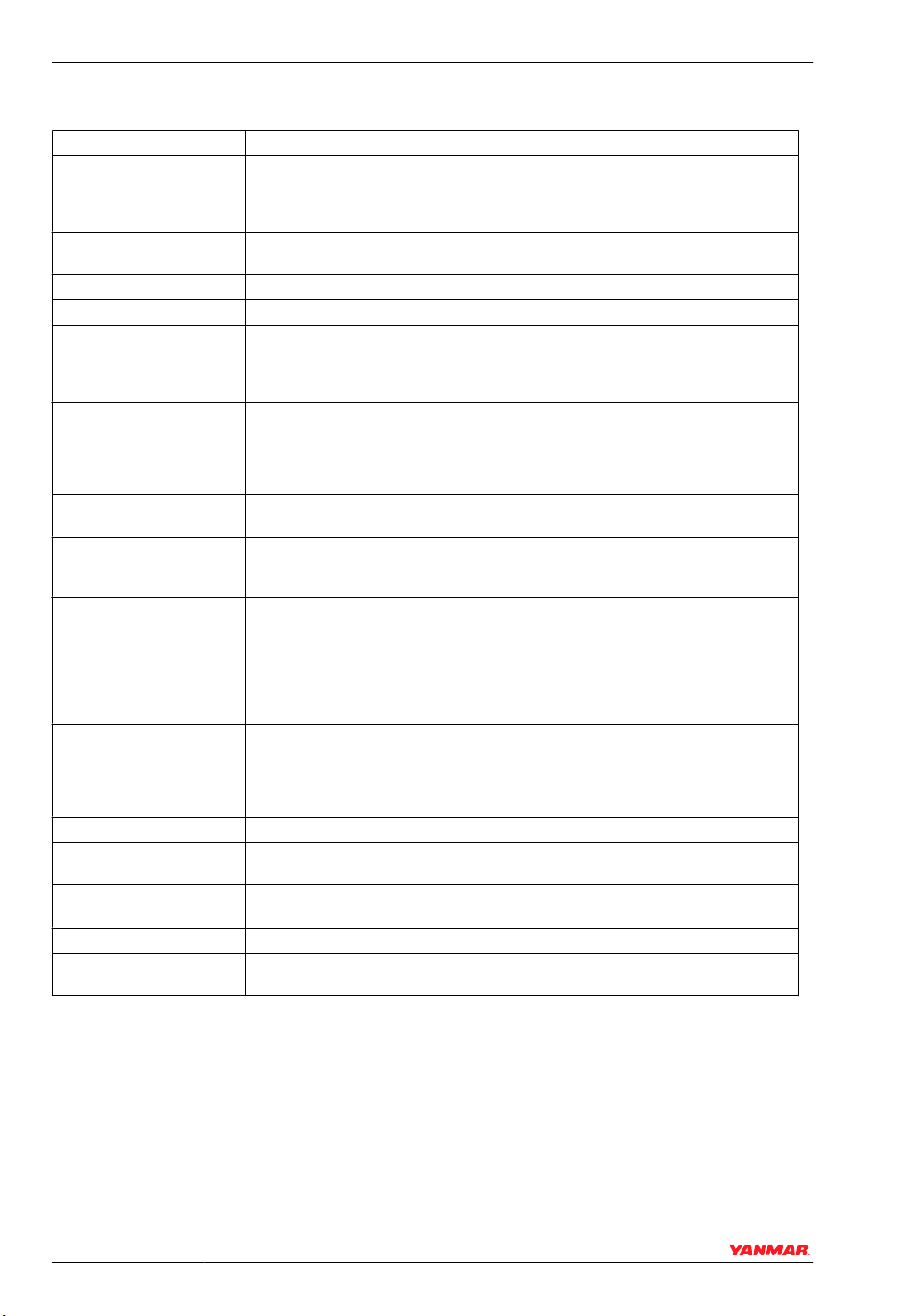
Name of Component Function
Fuel Filter / Water Separator (not supplied by
Yanmar)
Fuel Fine Filter Removes extremely fine contaminants from fuel prior to entering fuel injection
Fuel Feed Pump Pumps fuel from the tank to the fuel injection system.
Engine Oil Fill Port To add engine oil.
Engine Oil Filter Filters fine metal fragments and carbon from the engine oil. Filtered engine oil is
Coolant System There are two cooling systems: 1) closed cooling with coolant and 2) seawater.
Closed Cooling Circulation Pump
Seawater Pump Pumps seawater from outside vessel to the engine. The seawater pump is belt-
Coolant Fill Cap When the coolant temperature rises, the pressure inside the heat exchanger
Coolant Recovery Tank
Oil Cooler - Engine
Oil Cooler - Hydraulic A heat exchanger that cools the marine gear oil or power steering fluid using
Turbocharger The turbocharger pressurizes the air coming into the engine. It is powered by a
Air Filter The air filter removes dirt from the intake combustion air reducing engine wear.
Nameplates Nameplates are provided on the engine and the marine gear and have the model,
Removes dirt and water from the fuel. The filter element should be replaced periodically. See Replacing Fuel Filter / Water Separator Element on page 52.
The water separator should be drained periodically. See Draining the Fuel / Wa-
ter Separator on page 47.
system.
distributed to the engine's moving parts. The filter is a cartridge type and the
element should be replaced periodically. See Changing the Engine Oil and Re-
placing the Engine Oil Filter on page 48.
The engine is cooled by the closed cooling system. The closed system coolant
is cooled by seawater using a heat exchanger. The seawater also cools the marine gear or power steering oil, and the combustion intake air through cooler(s)
in an open circuit.
The centrifugal coolant pump circulates coolant inside the engine. The circulating
pump is driven by a poly V-belt.
driven and has a replaceable rubber impeller. Avoid impeller damage, do not
operate it without seawater.
increases, causing the pressure valve in the filler cap to open, forcing hot water
and steam through a rubber hose to the coolant recovery tank. When the engine
becomes cool and the pressure inside the coolant recovery tank drops, the vacuum valve in the filler cap opens and the coolant in the coolant recovery tank
returns to the heat exchanger through the hose and filler cap. This minimizes
coolant consumption.
The coolant fill cap valve releases vapor and hot water overflow to the coolant
recovery tank. When the engine stops and the coolant cools, the pressure in the
heat exchanger drops. The fill cap valve then opens to send coolant back from
the coolant recovery tank. This minimizes coolant consumption. The closed
cooling system coolant level can easily be checked and refilled in this tank.
A heat exchanger that cools high temperature engine oil using engine coolant.
seawater.
turbine that is driven by exhaust gases.
serial number and other data.
16 BY Series Operation Manual
© 2008 Yanmar Marine International

PRODUCT OVERVIEW
Name of Component Function
Electrical Panel (E-Box) The electrical panel houses the engine electrical system fuses, relays, and ECU.
Electrical Panel (E-Box)
Circuit Breaker
The ECU monitors data from the various sensors and controls such functions as
low-pressure fuel pump operation, fuel injection pressure, fuel injection system
volume, and the timing and volume of fuel injected by the Bosch electronic fuel
injectors. Throttle control is fly-by-wire meaning it is controlled by electric signals
from the helm. The throttle control is either analog or digital depending on the
level of control options installed. The ECU also uses sensor inputs to monitor
engine condition and will set a trouble code if a system or sensor indicates a
problem. In most cases, a Check Engine light will be displayed. The engine may
or may not run normally depending on the fault. Not all inputs are monitored by
the ECU. Low oil pressure and water in fuel are two examples. Either of these
conditions will result in a warning indicator and possible audible alarm. Low oil
pressure will also be indicated by the oil gauge at the helm (not available with
Classic Controls).
The electrical panel circuit breaker is installed in the positive (+) cable of the
electrical panel power lead, and provides overload protection for the electrical
panel. The electrical panel power leads must be connected directly to the battery,
and must have a breaker installed in the B+ (red) lead.
BY Series Operation Manual 17
© 2008 Yanmar Marine International

PRODUCT OVERVIEW
FUSES AND RELAYS
(2)
(4)
(1)
(3)
(13)
(14)
(15)
Figure 10
1 – Fuse F1 (3 A) - CAN Switched
Power
2 –
Fuse F2 (10 A) - Ignition
3 – Fuse F3 (15 A) - Fuel Supply
Pump
4 – Fuse F4 (30 A) - ECU Switched
Power
5 – Fuse F5 (20 A) - Power to Sensors
and Actuators
6 – Fuse F6 (10 A) - Auxiliary Power
7 – Jumper Fuse F7 (3 A) - Single /
Port Selection, default is single /
port (fuse in). Remove fuse for
starboard configuration.
8 – Jumper Fuse F8 (3 A) - CAN /
Analog Throttle Selection,
default is analog (fuse out).
Insert 3 A fuse to configure for
CAN.
9 – K1 - Starter Relay
10–K3 - Fuel Supply Pump Relay
11–K2 - Main Power Relay
12–ECU
13–Connector X1 - Communication
to Helm Display
14–Connector X21/1 - Engine Wiring
Harness
15–Connector X22/1 - Fuel Injector
Wiring Harness
(5)
(6)
(7)
(8)
(9)
(10)
0004043
*
(11)
(12)
To access the fuse and relay panel, remove
the four bolts from the E-Box cover and
remove cover.
NOTICE: The electrical panel cables must
be connected directly to the battery, and
must have a circuit breaker installed in the B
+ (red) lead.
* NEVER connect any additional devices to F2. F6 may be used however, it is not switched.
18 BY Series Operation Manual
© 2008 Yanmar Marine International
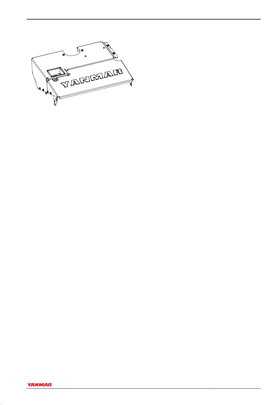
ENGINE COVER
0006552
Figure 11
To remove the cover from the engine,
remove all bolts, then lift cover from engine.
PRODUCT OVERVIEW
BY Series Operation Manual 19
© 2008 Yanmar Marine International

PRODUCT OVERVIEW
This Page Intentionally Left Blank
20 BY Series Operation Manual
© 2008 Yanmar Marine International

BEFORE YOU OPERATE
This section of the Operation Manual
describes the diesel fuel, engine oil, and
engine coolant specifications and how to
replenish them. It also describes the daily
engine checkout.
BY Series Operation Manual 21
© 2008 Yanmar Marine International
 Loading...