

Yanmar 2YM15, 3YM20, 3YM30E, 3YM30 Operation Manual

OPERATION MANUAL
MARINE ENGINES
2YM15
3YM20
3YM30E
3YM30
en
English

Disclaimers:
All information, illustrations and specifications in this manual are based on the latest
information available at the time of publishing. The illustrations used in this manual
are intended as representative reference views only. Moreover, because of our
continuous product improvement policy, we may modify information, illustrations
and/or specifications to explain and/or exemplify a product, service or maintenance
improvement. We reserve the right to make any change at any time without notice.
Yanmar and are registered trademarks of YANMAR CO., LTD. in
Japan, the United States and/or other countries.
All Rights Reserved:
No part of this publication may be reproduced or used in any form by any means graphic, electronic, or mechanical, including photocopying, recording, taping, or
information storage and retrieval systems - without the written permission of
YANMAR CO., LTD.
OPERATION MANUAL
MODEL
CODE
2YM15, 3YM20, 3YM30E, 3YM30
0AYMM-G00202
All Rights Reserved, Copyright

TABLE OF
CONTENTS
INTRODUCTION .............................................................. 1
YM SERIES EMISSION CONTROL SYSTEM
WARRANTY-USA, THE ENVIRONMENTAL
PROTECTION AGENCY (EPA) ONLY ...................... 2
RECORD OF OWNERSHIP ...................................... 3
SAFETY ........................................................................... 5
SAFETY PRECAUTIONS .......................................... 6
General Information ............................................. 6
Before You Operate............................................. 6
During Operation and Maintenance..................... 6
LOCATION OF SAFETY DECALS .......................... 10
PRODUCT OVERVIEW ................................................. 11
YANMAR YM SERIES FEATURES AND
APPLICATIONS ....................................................... 11
New Engine Break-In......................................... 12
COMPONENT IDENTIFICATION ............................ 13
Right Side (Viewed from Flywheel) - 2YM15 ..... 13
Left Side (Viewed from Flywheel) - 2YM15 ....... 13
Right Side (Viewed from Flywheel) - 3YM20 ..... 14
Left Side (Viewed from Flywheel) -3YM20 ........ 14
Right Side (Viewed from Flywheel) - 3YM30(E) 15
Left Side (Viewed from Flywheel) - 3YM30(E)... 15
NAMEPLATES ......................................................... 16
FUNCTION OF MAJOR COMPONENTS ................ 17
CONTROL EQUIPMENT ......................................... 18
Instrument Panel ............................................... 18
Single-Handle Remote Control Head ................ 24
YM Series Operation Manual

TABLE OF CONTENTS
BEFORE YOU OPERATE .............................................. 25
INTRODUCTION ...................................................... 25
SAFETY PRECAUTIONS......................................... 25
DIESEL FUEL........................................................... 26
Diesel Fuel Specifications .................................. 26
Filling the Fuel Tank........................................... 29
Bleeding the Fuel System .................................. 30
ENGINE OIL ............................................................. 31
Engine Oil Specifications .................................. 31
Engine Oil Viscosity .......................................... 31
Checking the Engine Oil..................................... 32
Adding Engine Oil .............................................. 32
MARINE GEAR OR SAIL DRIVE OIL ...................... 33
Marine Gear Oil Specifications........................... 33
Sail Drive Oil Specifications- SD20 .................... 33
Checking Marine Gear Oil .................................. 33
Adding Marine Gear Oil...................................... 33
Checking and Adding Sail Drive Oil ................... 33
ENGINE COOLANT ................................................. 34
Engine Coolant Specifications ........................... 34
Coolant (Closed Cooling System) ...................... 34
Checking and Adding Coolant............................ 35
CRANKING THE ENGINE........................................ 37
ENGINE OPERATION .................................................... 39
INTRODUCTION ...................................................... 39
SAFETY PRECAUTIONS......................................... 39
STARTING THE ENGINE ........................................ 41
If the Engine Fails to Start.................................. 42
Starting at Low Temperatures ............................ 42
After the Engine has Started .............................. 43
REMOTE CONTROL HANDLE OPERATION .......... 44
Acceleration and Deceleration ........................... 44
Shifting the Engine ............................................. 44
CAUTIONS DURING OPERATION.......................... 45
SHUTTING DOWN THE ENGINE ............................ 46
Normal Shutdown............................................... 46
Emergency Shutdown ........................................ 47
CHECKING THE ENGINE AFTER OPERATION..... 48
PERIODIC MAINTENANCE ........................................... 49
INTRODUCTION ...................................................... 49
SAFETY PRECAUTIONS......................................... 49
YM Series Operation Manual

12/05
TABLE OF CONTENTS
PRECAUTIONS ....................................................... 51
The Importance of Periodic Maintenance.......... 51
Performing Periodic Maintenance ..................... 51
The Importance of Daily Checks ....................... 51
Keep a Log of Engine Hours and Daily Checks 51
Yanmar Replacement Parts .............................. 51
Tools Required .................................................. 51
Ask Your Authorized Yanmar Marine Dealer or
Distributor for Help............................................. 51
Tightening Fasteners ......................................... 52
EPA MAINTENANCE REQUIREMENTS................. 53
EPA Requirements for USA and Other
Applicable Countries.......................................... 53
Conditions to Ensure Compliance with
EPA Emission Standards .................................. 53
Inspection and Maintenance.............................. 53
Installing Sample Port........................................ 54
PERIODIC MAINTENANCE SCHEDULE ................ 55
Inspection and Maintenance of
EPA Emission-Related Parts............................. 58
PERIODIC MAINTENANCE PROCEDURES .......... 59
Daily Checks...................................................... 59
After Initial 50 Hours of Operation ..................... 60
Every 50 Hours of Operation ............................. 65
Every 100 Hours of Operation ........................... 67
Every 150 Hours of Operation ........................... 67
Every 250 Hours of Operation ........................... 68
Every 1000 Hours of Operation ......................... 71
TROUBLESHOOTING ................................................... 75
SAFETY PRECAUTIONS ........................................ 75
TROUBLESHOOTING AFTER STARTING ............. 75
TROUBLESHOOTING INFORMATION ................... 76
TROUBLESHOOTING CHART................................ 77
LONG-TERM STORAGE ............................................... 79
PREPARE ENGINE FOR LONG-TERM STORAGE 79
DRAIN SEAWATER COOLING SYSTEM ............... 80
YM Series Operation Manual

TABLE OF CONTENTS
SPECIFICATIONS .......................................................... 83
PRINCIPAL ENGINE SPECIFICATIONS................. 83
2YM15 Engine Specifications ............................ 84
3YM20 Engine Specifications ............................ 85
3YM30E Engine Specifications .......................... 86
3YM30 Engine Specifications ............................ 87
Marine Gear and Sail Drive Specifications......... 88
SYSTEM DIAGRAMS..................................................... 89
PIPING DIAGRAMS ................................................. 89
WIRING DIAGRAMS ................................................ 94
EPA WARRANTY USA ONLY ....................................... 97
YANMAR CO., LTD. LIMITED EMISSION
CONTROL SYSTEM WARRANTY - USA ONLY ..... 97
Your Warranty Rights and Obligations:.............. 98
Warranty Period: ................................................ 98
Warranty Coverage: ........................................... 99
Exclusions: ......................................................... 99
Owner’s Responsibility:...................................... 99
Customer Assistance: ........................................ 99
EMISSION SYSTEM WARRANTY............................... 101
NON-ROAD EMISSION SYSTEM WARRANTY .... 101
Yanmar Co., Ltd. Limited Emission
Control System Warranty - USA Only .............. 101
Maintenance Log.............................................. 104
YM Series Operation Manual

INTRODUCTION
Welcome to the world of Yanmar Marine!
Yanmar Marine offers engines, drive
systems and accessories for all types of
boats, from runabouts to sailboats, and
from cruisers to mega yachts. In marine
leisure boating, the worldwide reputation of
Yanmar Marine is second to none. We
design our engines to respect nature. This
means quieter engines, with minimal
vibrations, cleaner than ever. All of our
engines meet applicable regulations,
including emissions, at the time of
manufacture.
To help you enjoy your Yanmar YM series
engine for many years to come, please
follow these recommendations:
• Read and understand this Operation
Manual before you operate the machine
to ensure that you follow safe operating
practices and maintenance procedures.
• Keep this Operation Manual in a
convenient place for easy access.
•If this Operation Manual is lost or
damaged, order a new one from your
authorized Yanmar Marine dealer or
distributor.
• Make sure this manual is transferred to
subsequent owners. This manual should
be considered a permanent part of the
engine and remain with it.
• Constant efforts are made to improve the
quality and performance of Yanmar
products, so some details included in
this Operation Manual may differ slightly
from your engine. If you have any
questions about these differences,
please contact your authorized Yanmar
Marine dealer or distributor.
• The specifications and components
(instrument panel, fuel tank, etc.)
described in this manual may differ from
ones installed on your vessel. Please
refer to the manual provided by the
manufacturer of these components.
• Refer to the Yanmar Limited Warranty
Handbook for a complete warranty
description.
YM Series Operation Manual 1

INTRODUCTION
YM SERIES EMISSION CONTROL SYSTEM WARRANTY-USA, THE ENVIRONMENTAL PROTECTION AGENCY (EPA) ONLY
YM series engines come with an emission control system warranty. In all states, 2009 and
later compression-ignition engines must be designed, built and equipped to meet the
United States EPA emissions standards. Yanmar warrants the emission control system on
your YM series engine for the periods of time listed below.
Emission Control Certification
Model Year 2011 2012 2013 2014
2YM15 EPA marine CI Tier 3
3YM20 EPA marine CI Tier 3
3YM30E
3YM30 EPA marine CI Tier 3 intermediate -
-
Note: Since 2013, the 3YM30 does not comply with the EPA regulation.
EPA marine CI Tier 3
intermediate (NTE)
-
2 YM Series Operation Manual

12/05
INTRODUCTION
RECORD OF OWNERSHIP
Take a few moments to record the information you need when you contact Yanmar for
service, parts or literature.
Engine Model: __________________________________________________________
Engine Serial No.: _______________________________________________________
Date Purchased: ________________________________________________________
Dealer: ________________________________________________________________
Dealer Phone: __________________________________________________________
YM Series Operation Manual 3

INTRODUCTION
This Page Intentionally Left Blank
4 YM Series Operation Manual

SAFETY
DANGER
WARNING
CAUTION
NOTICE
Yanmar considers safety of great
importance and recommends that anyone
that comes into close contact with its
products, such as those who install,
operate, maintain or service Yanmar
products, exercise care, common sense
and comply with the safety information in
this manual and on the machine’s safety
decals. Keep the labels from becoming
dirty or torn and replace them if they are
lost or damaged. Also, if you need to
replace a part that has a label attached to
it, make sure you order the new part and
label at the same time.
This safety alert symbol
appears with most safety
statements. It means
A
attention, become alert,
your safety is involved!
Please read and abide by
the message that follows
the safety alert symbol.
Indicates a hazardous situation which,
if not avoided, will result in death or
serious injury.
Indicates a hazardous situation which,
if not avoided, could result in death or
serious injury.
Indicates a hazardous situation which,
if not avoided, could result in minor or
moderate injury.
Indicates a situation which can cause
damage to the machine, personal property
and / or the environment, or cause the
equipment to operate improperly.
YM Series Operation Manual 5

SAFETY
DANGER
WARNING
SAFETY PRECAUTIONS
General Information
There is no substitute for common sense
and careful practices. Improper practices
or carelessness can cause burns, cuts,
mutilation, asphyxiation, other bodily injury
or death. This information contains general
safety precautions and guidelines that
must be followed to reduce risk to personal
safety. Special safety precautions are
listed in specific procedures. Read and
understand all of the safety precautions
before operation or performing repairs or
maintenance.
Before You Operate
The safety messages that follow have
DANGER level hazards.
Never permit anyone to install
or operate the engine without
proper training.
Read and understand this
Operation Manual before you operate or
service the engine to ensure that you
follow safe operating practices and
maintenance procedures.
• Safety signs and labels are additional
reminders for safe operating and
maintenance techniques.
• Consult authorized Yanmar Marine
dealer or distributor for additional
training.
During Operation and Maintenance
The safety messages that follow have
WARNING level hazards.
Explosion Hazard
While the engine is running
or the battery is charging,
hydrogen gas is being
produced and can be easily
ignited. Keep the area
around the battery
well-ventilated and keep sparks, open
flames and any other form of ignition
out of the area.
Fire and Explosion Hazard
Diesel fuel is flammable and explosive
under certain conditions.
Never use a shop rag to catch the fuel.
Wipe up all spills immediately.
Never refuel with the engine running.
Fire Hazard
Undersized wiring systems
can cause an electrical fire.
Store any containers containing fuel or
other flammable products in a
well-ventilated area, away from any
combustibles or source of ignition.
Store any equipment in a designated
area away from moving parts.
Never use the engine compartment for
storage.
6 YM Series Operation Manual

12/05
WARNING
Sever Hazard
Rotating parts can cause
severe injury or death.
Never wear jewelry,
unbuttoned cuffs, ties or
loose-fitting clothing and
always tie long hair back when working
near moving / rotating parts such as the
flywheel or PTO shaft. Keep hands, feet
and tools away from all moving parts.
Alcohol and Drug Hazard
Never operate the engine
while under the influence of
alcohol or drugs, or when
feeling ill.
Exposure Hazard
Always wear personal
protective equipment
including appropriate
clothing, gloves, work
shoes, and eye and hearing protection
as required by the task at hand.
SAFETY
Exhaust Hazard
Never block windows, vents
or other means of
ventilation if the engine is
operating in an enclosed
area. All internal combustion engines
create carbon monoxide gas during
operation and special precautions are
required to avoid carbon monoxide
poisoning.
Sudden Movement Hazard
Never operate the engine while wearing
a headset to listen to music or radio
because it will be difficult to hear the
warning signals.
Burn Hazard
Some of the engine
surfaces become very hot
during operation and
shortly after shutdown.
Keep hands and other body
parts away from hot engine surfaces.
YM Series Operation Manual 7

SAFETY
CAUTION
NOTICE
The safety messages that follow have
CAUTION level hazards.
Poor Lighting Hazard
Ensure that the work area is adequately
illuminated. Always install wire cages
on portable safety lamps.
Too l Ha z a r d
Always use tools appropriate for the
task at hand and use the correct size
tool for loosening or tightening
machine parts.
Flying Object Hazard
Always wear eye protection when
servicing the engine or when using
compressed air or high-pressure water.
Dust, flying debris, compressed air,
pressurized water or steam may injure
your eyes.
Coolant Hazard
Wear eye protection and
rubber gloves when you
handle engine coolant. If
contact with the eyes or skin should
occur, flush eyes and wash immediately
with clean water.
The safety messages that follow have
NOTICE level hazards.
It is important to perform daily checks as
listed in the Operation Manual. Periodic
maintenance prevents unexpected
downtime, reduces the number of
accidents due to poor engine performance
and helps extend the life of the engine.
Consult authorized Yanmar Marine dealer
or distributor if you need to operate the
engine at high altitudes. At high altitudes
the engine will lose power, run rough and
produce exhaust gases that exceed the
design specifications.
Always be environmentally
responsible.
Follow the guidelines of the
EPA or other governmental
agencies for the proper disposal of
hazardous materials such as engine oil,
diesel fuel and engine coolant. Consult the
local authorities or reclamation facility.
Never dispose of hazardous materials by
dumping them into a sewer, on the ground,
or into ground water or waterways.
If a Yanmar Marine Engine is installed at
an angle that exceeds the specifications
stated in the Yanmar Marine Installation
Manuals, engine oil may enter the
combustion chamber causing excessive
engine speed, white exhaust smoke and
serious engine damage. This applies to
engines that run continuously or those that
run for short periods of time.
8 YM Series Operation Manual

12/05
NOTICE
If you have an installation with two or three
engines and only one engine is operating,
the water pickup (thru-hull) of the
non-running engine(s) should be closed.
This will prevent water from being forced
past the seawater pump and eventually
finding its way into the engine. The result
of water entering the engine could cause
seizure or other serious problems.
If you have an installation with two or three
engines, and only one engine is operating,
please note that if the propeller shaft
thru-hull (stuffing box) is lubricated by
engine water pressure and the engines are
interconnected, care must be taken that
water from the running engine does not
enter the exhaust of the non-running
engine(s). This water could cause seizure
of the non-running engine(s). Consult
authorized Yanmar Marine dealer or
distributor for a complete explanation of
this condition.
SAFETY
If you have an installation with two or three
engines, and only one engine is operating,
it is important to limit the amount of throttle
applied to the running engine. If you
observe black smoke or movement of the
throttle does not increase engine speed,
you are overloading the engine that is
running. Immediately throttle back to
approximately 2/3 throttle or to a setting
where the engine performs normally.
Failure to do so may cause the running
engine to overheat or cause excess
carbon buildup which may shorten the
engine’s life.
Never turn off the battery switch (if
equipped) or short the battery cables
during operation. Damage to the electrical
system will result.
YM Series Operation Manual 9

SAFETY
051101-00X00
1
2
3
LOCATION OF SAFETY DECALS
Figure 1, show the location of safety decals on Yanmar YM series marine engines.
YM Engines
Figure 1
1–Part Number: 128990-07270
2–Part Number: 128377-07350
3–Part Number: 196630-12980
10 YM Series Operation Manual

PRODUCT OVERVIEW
YANMAR YM SERIES FEATURES AND APPLICATIONS
The YM series are four-stroke swirl
pre-combustion chamber diesel engines
equipped with liquid coolant systems.
The 2YM15 is a 2-cylinder engine and is
naturally aspirated.
The 3YM20 is a 3-cylinder engine and is
naturally aspirated.
The 3YM30E, 3YM30 is a 3-cylinder
engine and is naturally aspirated.
The engines are equipped with a marine
gear or sail drive unit.
These engines are designed for pleasure
craft use and complied with EPA regulation
Tier3 marine from 2009 year.
It is recommended that new vessels be
propped so the engines can operate at 100
to 200 min
output power engine speed (3700 to 3800)
to allow for some added weight and hull
resistance.
The engine must be able to reach the
Maximum Rated Power engine speed
(3600) under full load at all times.
-1
above the Maximum Rated
Failure to do so can lead to reduced vessel
performance, lead to increased smoke
levels and cause permanent damage to
your engine.
The engine must be installed correctly with
coolant lines, exhaust gas lines and
electrical wiring. Any auxiliary equipment
attached to the engine should be easy to
use and accessible for service. To handle
the drive equipment, propulsion systems
(including the propeller) and other inboard
equipment, always observe the
instructions and cautions given in the
operation manuals supplied by the
shipyard and equipment manufacturers.
The YM series engines are designed to be
operated at maximum throttle (3600 min
for less than 5% of total engine time (30
minutes out of every 10 hours) and
cruising speed (3400 min
The laws of some countries may require
hull and engine inspections, depending on
the use, size and cruising area of the boat.
The installation, fitting and surveying of
this engine all require specialized
knowledge and engineering skills. See
Yanmars local subsidiary in your region or
your authorized Yanmar Marine dealer or
distributor.
-1
or less).
-1
)
YM Series Operation Manual 11

PRODUCT OVERVIEW
NOTICE
New Engine Break-In
As with all reciprocating engines, the way
your engine is operated during its first 50
hours of operation plays a very significant
role in determining how long it will last and
how well the engine will perform over its
lifetime.
A new Yanmar diesel engine must be
operated at suitable speeds and power
settings during the break-in period to make
the sliding parts, such as piston rings,
break-in properly and to stabilize engine
combustion.
During the break-in period, the engine
coolant temperature gauge should be
monitored; temperature should be
between 71° and 87°C (160° and 190°F).
During the first 10 hours of operation, the
engine should be run at maximum engine
speed minus 400 to 500 min
(approximately 60 to 70% of load) most of
the time. This will ensure the sliding parts
break in properly. During this period, avoid
operating at maximum engine speed and
load to avoid damaging or scoring sliding
parts.
Do not operate at WOT (wide open
throttle) for more than a minute at a time
during the first 10 hours of operation.
Do not operate the engine at low idle or at
low speed and light load for more than
30 minutes at a time. Since unburned fuel
and engine oil will adhere to the piston
rings when operating at low speeds for
long periods, this will interfere with proper
movement of the rings and the engine oil
consumption may increase. Low idle
speed does not allow break-in of sliding
parts.
-1
If operating engine at low speed and light
load, you must race the engine to clean the
carbon from the cylinders and fuel injection
valve.
Perform this procedure in open waters:
• With the clutch in NEUTRAL, accelerate
from the low-speed position to the
high-speed position briefly.
• Repeat this process five times.
Once past the initial 10 hours until 50
hours, the engine should be used over its
full operating range, with special emphasis
on running at relatively high power
settings. This is not the time for an
extended cruise at idle or low speed. The
boat should be run at maximum speed
minus 400 min
(approximately 70% load), with a 10
minute run at maximum minus 200 min
(approximately 80% load) every
30 minutes and a 4 to 5 minute period of
operation at WOT (wide open throttle)
once each 30 minutes. During this period,
be sure not to operate your engine at low
speed and light load for more than
30 minutes. If operating engine at low
speed and light load by necessity, just
after the low idle operation, be sure to race
the engine.
To complete engine break-in, perform
After Initial 50 Hours of Operation
maintenance procedures. After Initial 50
Hours of Operation on page 60.
-1
most of the time
-1
12 YM Series Operation Manual

12/05
051098-00X00
8
7
5
6
COMPONENT IDENTIFICATION
PRODUCT OVERVIEW
Left Side (Viewed from Flywheel)
- 2YM15
Right Side (Viewed from Flywheel) - 2YM15
Figure 1 and Figure 2 illustrate a typical
version of a 2YM15 engine. Your engine
may have different equipment from that
illustrated.
2
3
1
9
Figure 1
4
5
6
7
8
0004781
3
2
1
Figure 2
1 – Seawater Pump
2 – Coolant Filler Cap
3 – Engine Nameplate (on rocker
arm cover)
4 – Coolant Tank / Heat Exchanger
5 – Exhaust Manifold
6 – Starter Motor
7 – Shift Lever
8–Alternator
4
1 – Intake Silencer (air cleaner)
2 – Intake Manifold
3 – Fuel Filter
4 – Fuel Injection Pump
5 – Engine Oil Dipstick
6 – Engine Oil Filler Cap
7 – Fuel Feed Pump
8 – Engine Oil Filter
9–Marine Gear
YM Series Operation Manual 13

PRODUCT OVERVIEW
1
2
3
4
5
6
7
8
9
0004783
051099-00X00
4
5
6
7
8
Right Side (Viewed from Flywheel) - 3YM20
Figure 3 and Figure 4 illustrate a typical
version of a 3YM20 engine. Your engine
may have different equipment from that
illustrated.
Figure 3
1 – Intake Silencer (air cleaner)
2 – Intake Manifold
3 – Fuel Filter
4 – Fuel Injection Pump
5 – Engine Oil Dipstick
6 – Engine Oil Filler Cap
7 – Fuel Feed Pump
8 – Engine Oil Filter
9–Marine Gear
Left Side (Viewed from Flywheel)
-3YM20
23
1
Figure 4
1 – Seawater Pump
2 – Coolant Filler Cap
3 – Engine Nameplate (on rocker
arm cover)
4 – Coolant Tank / Heat Exchanger
5 – Exhaust Manifold
6 – Starter Motor
7 – Shift Lever
8–Alternator
14 YM Series Operation Manual

12/05
1
2
4
5
6
7
8
9
3
0004785
4
5
6
7
8
Right Side (Viewed from Flywheel) - 3YM30(E)
PRODUCT OVERVIEW
Left Side (Viewed from Flywheel)
- 3YM30(E)
Figure 5 and Figure 6 illustrate a typical
version of a 3YM30(E) engine. Your
engine may have different equipment from
that illustrated.
Figure 5
1 – Intake Silencer (air cleaner)
2 – Intake Manifold
3 – Fuel Filter
4 – Fuel Injection Pump
5 – Engine Oil Dipstick
6 – Engine Oil Filler Cap
7 – Fuel Feed Pump
8 – Engine Oil Filter
9–Marine Gear
2
1
051100-00X00
Figure 6
1 – Seawater Pump
2 – Coolant Filler Cap
3 – Engine Nameplate (on rocker
arm cover)
4 – Coolant Tank / Heat Exchanger
5 – Exhaust Manifold
6 – Starter Motor
7 – Shift Lever
8–Alternator
3
YM Series Operation Manual 15

PRODUCT OVERVIEW
129670-07201
Continuous power kW
Speed of prop.shaft
Gear Model
min
-1
Fuel stop power kW
MFG.DATE
min
-1
/
/
min
-1
Model
ENG.No.
/
kW
㻹㻻㻰㻱㻸
㻹㻲㻳㻚㻌㻺㻻㻚
㻳㻱㻭㻾㻌㻾㻭㼀㻵㻻
㻻㻵㻸㻌
177524-02903
㻹㻲㻳㻚㻺㼛㻚
㻼㻭㻿㻿㻱㻰
㻹㻭㻾㻷
㻹㻻㻰㻱㻸
196420-02124
NAMEPLATES
The nameplates of Yanmar YM series
engines are shown in Figure 7. Check the
engine’s model, output, min
number on the nameplate. Please replace
if damaged or lost.
The engine nameplate is attached to the
engine rocker arm cover.
Figure 7
-1
and serial
The marine gear nameplate (Figure 8) is
attached to the marine gear. Check the
marine gears model, gear ratio, oil used,
oil quantity and serial number.
Figure 8
The sail drive nameplate (Figure 9) is
attached to the sail drive. Check the sail
drive model and serial number.
16 YM Series Operation Manual
Figure 9

12/05
PRODUCT OVERVIEW
FUNCTION OF MAJOR COMPONENTS
Name of Component Function
Fuel Filter Removes dirt and water from the fuel. Drain the filter periodically. The filter element should be
Fuel Feed Pump Pumps fuel from the tank to the fuel injection system. Pushing the manual lever on the side of
Fuel Feed Lever Moving the fuel feed lever up and down feeds the fuel. The lever is used to bleed air from the
Engine Oil Filler Port Filler port for engine oil.
Engine Oil Filter Filters fine metal fragments and carbon from the engine oil. Filtered engine oil is distributed to
Marine Gear Filler Port Filler port for marine gear lube oil. Located on top of the marine gear case.
Cooling System There are two cooling systems: closed cooling with coolant (fresh water) and seawater. The
Closed Cooling Circulation
Pump
Seawater Pump Pumps seawater from outside vessel to the engine. The seawater pump is gear-driven and
Coolant Filler Cap The filler cap on the heat exchanger / coolant tank covers the water supply port. The cap has
Reservoir The pressure valve in the filler cap releases vapor and hot water overflow to the reservoir.
Engine Oil Cooler A heat exchanger that cools high temperature engine oil using coolant.
Intake Silencer (Air Cleaner) The intake silencer guards against dirt in the air and reduces the noise of air intake.
Nameplates Nameplates are provided on the engine and the marine gear and have the model, serial
Starter Starter motor for the engine; powered by the battery.
Alternator Driven by a belt and generates electricity and charges the battery.
Engine Oil Dipstick Gauge stick for checking the engine oil level.
replaced periodically. The water separator (if equipped) should be drained periodically. See
Draining Fuel Filter / Water Separator on page 65.
the feed pump supplies fuel to the engine when fuel priming is needed.
fuel system after running out of fuel.
the engine’s moving parts. The filter is a cartridge type and the element should be replaced
periodically. See Changing the Engine Oil on page 61.
engine is cooled by the closed cooling circuit. The closed circuit is cooled by seawater using
a heat exchanger. The seawater also cools the engine / marine gear oil.
The centrifugal water pump circulates coolant inside the engine. The circulating pump is
driven by a V-ribbed belt.
has a replaceable rubber impeller. Do not operate it without seawater, as this will damage the
impeller.
a pressure regulating valve. When the cooling water temperature rises, the pressure rises
inside the coolant system.
When the engine stops and the coolant cools, the pressure in the coolant tank drops. The filler
cap vacuum valve then opens to send water back from the reservoir. This minimizes coolant
consumption. The closed cooling system coolant level can easily be checked and refilled in
this tank.
number and other data. See Nameplates on page 16
YM Series Operation Manual 17

PRODUCT OVERVIEW
042563-00X00
4
213
042564-00X00
042565-00X00
042566-00X00
042567-00X00
CONTROL EQUIPMENT
The equipment in the control room makes remote control operation possible. It consists of
the instrument panel, which is connected to the engine by a wire harness, and the remote
control handle, which is connected by control cables to the engine control lever and
marine gear.
Instrument Panel
Equipment and Functions
The instrument panel is located at the helm. The following instruments enable you to start
or stop the engine and to monitor its condition during operation.
B20-Type
1 – Alarm lamps
2–Tachometer
Control panel switches
All switches are push-buttons.
Start switch
Pushing this switch operates
the starter and starts the
engine.
Stop switch
Pushing this switch stops the
engine.
Figure 10
3–LCD
4 – Switches (push-buttons)
Glow switch
Pushing this switch for the
specified time heats the glow
plug in the combustion
chamber. It becomes red-hot,
facilitating fuel ignition. This
assists starting in cold weather.
Power switch
Pushing this switch turns on or
off the power.
18 YM Series Operation Manual

12/05
PRODUCT OVERVIEW
Meters
Instrument Function
Tachometer Shows engine rotation speed.
Hourmeter Shows number of operating hours. Can be used as a guide for periodic
maintenance checks. The hourmeter is located at the bottom of the
tachometer.
Panel Lights When the power switch is pushed, the gauges will illuminate for easier viewing.
Note: The LCD on the instrument panel show hourmeter, display brightness and
battery voltage.
Indicators and Alarms (Optional)
When a sensor detects a problem during operation, the indicator on the instrument panel
will light and an alarm will sound. Indicators are located on the instrument panel and the
alarms are located on the back of the panel. Under normal operating conditions, the
indicators are off.
Battery Low Charge Indicator
When the alternator output is too low, the indicator will light. When
charging begins, the indicator will turn off.
Coolant High Temperature Indicator and Alarm
When coolant temperature reaches the maximum allowable temperature
(95°C [203°F] or higher), the indicator will light and the alarm will sound.
Continuing operation at temperatures exceeding the maximum limit will
result in damage and seizure. Check the load and troubleshoot the
cooling system.
Engine Oil Low Pressure Indicator and Alarm
When the engine oil pressure falls below normal, the oil pressure sensor
will send a signal to the indicator, causing it to light and the alarm to
sound. Stop operation to avoid damage to the engine. Check the oil level
and troubleshoot the lubrication system.
Water in Sail Drive Seal Indicator and Alarm
When water is detected between the seals of the sail drive, the indicator
will light and the alarm will sound.
YM Series Operation Manual 19

PRODUCT OVERVIEW
Scroll
Push and hold
(display will blink when
ready)
Scroll
100, 80, 60, 40, 20, 0
(value will be set after
3 seconds)
1 2 3
051899-00EN00
Engine hour ( >300 min-1)
Coolant temperature
Backlighting Brightness
Oil pressure
Battery voltage
LCD control (hourmeter, display brightness, battery voltage)
You can switch (scroll) between displays
by pressing the buttons on the bottom.
• Switching screens by pressing the
right button (Pressing the left button
switches the screens in the opposite
direction.)
Press the power switch.
• After 4 seconds, the LCD shows the
hourmeter.
Pressing the right button on the bottom of
the LCD shows the temperature display.
This feature is not available on this
engine.
Pressing the right button again shows the
LCD brightness settings.
To set the brightness of the backlight:
Press the left button continuously and
the digits of the LCD start flashing.
In this condition, press the right button
to decrease the brightness and the left
button to increase the brightness.
(The brightness changes in 6 steps of
20 %.)
Figure 1
To set the desired brightness, do not
touch the buttons for 3 seconds.
Note: Continuously pressing means
holding the button for approx. 2
seconds.
Next, press the right button to show the
pressure display.
This feature is not available on this
engine.
Press again to show the battery voltage.
Pressing the button once more returns the
display to the initial hourmeter.
20 YM Series Operation Manual
Return to hourmeter
Figure 11
12/05
043719-02EN02
1 2
3
4
7
8
5
6
Engine type select
Select
Exit setup
Scroll
Return to LCD control
Scroll
Select
PRODUCT OVERVIEW
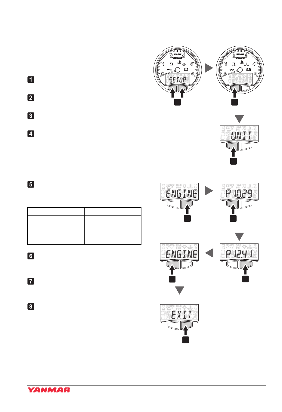
Setup Screen Access and Control
(Setting the engine speed pulse value for B20/C30 type panel)
Use the buttons on the bottom of the LCD
display to set the instrument panel.
Press the left button to switch between
displays.
Press and hold both buttons until “SET
UP” appears.
Press the left button and go to the
screen “UNIT”.
Press the left button and go to the next
screen “ENGINE”.
Confirm that the display says
“ENGINE”. Press the right button and
“P****” appears.
Note: The pre-set value of speed pulse
is indicated on the box of each
panel.
Next, press the left button and select
the speed pulse value for each engine
model.
Figure 2
Engine model Speed pulse value
YM with HITACHI
alternator
YM with VALEO
alternator
After confirming the value is changed
correctly, press the right button to
return to the “ENGINE” screen.
Press the left button again to go from
the “ENGINE” screen to the “EXIT”
screen.
After confirming the display, press the
right button to re-start the panel and
return to the hourmeter display.
10.29
12.41
Figure 12
YM Series Operation Manual 21
PRODUCT OVERVIEW
NOTICE
Alarms
Checking the Warning Devices
Before and after engine start, make sure that the instruments and warning devices
operate correctly.
If the engine runs out of coolant or lubricating oil and the instruments and warning devices
fail, they can not give you warning to prevent accidents. This can also lead to incorrect
operation and cause further malfunctions of the engine.
Before Engine Start
1. Turn on the battery switch.
2. Push the power switch on.
• All alarm lamps light up for 4 seconds.
• After 4 seconds, the charge lamp and the lubricating oil pressure alarm lamp light up,
and the hourmeter is displayed.
• The alarm buzzer sounds until the engine starts.
After Engine Start
After engine start, make sure that the warning devices operate correctly and according to
“After start” in the below table.
• All alarm lamps turn off. The above check tells you whether the electric circuit for the
warning lamps and alarm buzzer operate correctly. If they do not operate correctly,
inspection and repair are required. Consult your dealer or distributor for repairs.
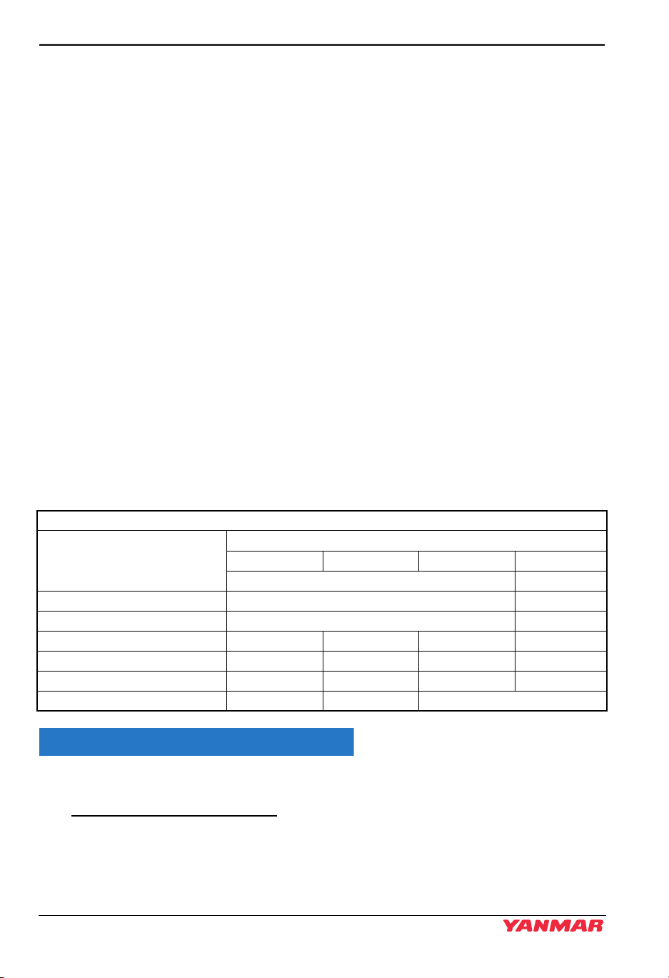
Correct operation of the warning devices
Instrument panel (power switch) Power ON
Immediately After 2 seconds After 4 seconds
Before start After start
Starter switch OFF ON
Alarm buzzer ON OFF
Charge lamp ON ON ON OFF
Coolant temperature lamp ON ON OFF OFF
Engine lubricating oil pressure lamp ON ON ON OFF
LCD display Yanmar Full display Hourmeter
When the warning devices are activated and normal operation is impossible, stop the
engine and do not use it until the problem has been solved.
22 YM Series Operation Manual

12/05
043801-00E00
F1A - 3 AMP Fuse
Buzzer
ACC Output
PRODUCT OVERVIEW
Accessory power output
The harness attached to the panel has a terminal where the signal that is synchronized to
the panel power supply can be taken off. (Figure 13) ( Refer to the Wiring Diagrams on
page 94.)
The maximum current of this output terminal is 3 A. Do not use a current higher than 3 A.
For the content of the output terminal, refer to the Wiring Diagrams on page 94.
Figure 3
Figure 13
YM Series Operation Manual 23

PRODUCT OVERVIEW
Single-Handle Remote Control Head
Figure 4
3
1
4
Figure 14
Note: Direction of travel will vary
depending on installation
location.
1 – Low Speed - FWD or REV
2 – Low Speed - FWD or REV
3 – NEUTRAL - Power to the
propeller shaft is cut off and
the engine idles
4 – Maximum Engine Speed - FWD
or REV
5 – Maximum Engine Speed - FWD
or REV
A single handle-type (Figure 14) should
be used to operate the marine gear clutch
(NEUTRAL, FORWARD and REVERSE)
and to control the engine speed.
2
5
0004504
2
1
0004511
Figure 15
Note: Yanmar recommends the use of
a single-handle type for the
remote control system. If only a
two-handle type is available in
the market, reduce engine
speed to 1000 min
-1
or less
before engaging and
disengaging the marine gear
clutch.
The handle controls the direction of the
boat (ahead or astern) and also acts as an
accelerator by increasing engine speed as
the control handle is pushed further in
FORWARD or REVERSE directions.
When the handle is pulled out
(Figure 15, (1)), the engine speed can be
controlled without engaging the marine
gear. The marine gear remains in
NEUTRAL, no load
position. Turn the knob (Figure 15, (2))
counterclockwise to move the handle or
clockwise to lock the handle.
24 YM Series Operation Manual
 Loading...