

Page 1

SERVICE MANUAL
INDUSTRIAL ENGINES 3TNV88F
SERVICE MANUAL
INDUSTRIAL ENGINES
3TNV88F
0BTN4-G00400
PRINTED IN JAPAN
Page 2

California
product improvement policy, we may modify information, illustrations and/or specifications
Proposition 65 Warning
Diesel engine exhaust and some of its
constituents are known to the state of
California to cause cancer, birth
defects, and other reproductive harm.
Proposition 65 Warning
Battery posts, terminals, and related
accessories contain lead and lead
compounds, chemicals known to the
state of California to cause cancer and
reproductive harm.
Wash hands after handling.
California
Foreword:
This Service Manual has been developed for the exclusive use of service and repair
professionals such as YANMAR authorized distributors and YANMAR authorized dealers.
It is written with these professionals in mind and may not contain the necessary detail or
safety statements that may be required for a non-professional to perform the service or
repair properly and/or safely. Please contact an authorized YANMAR repair or service
professional before working on your YANMAR product.
Disclaimers:
All information, illustrations and specifications in this manual are based on the latest
information available at the time of publishing. The illustrations used in this manual are
intended as representative reference views only. Moreover, because of our continuous
to explain and/or exemplify a product, service or maintenance improvement. We reserve
the right to make any change at any time without notice. YANMAR and are
registered trademarks of YANMAR CO., LTD. in Japan, the United States and/or other
countries.
Head Office:
YANMAR CO., LTD.
Umeda Gate Tower 1-9 Tsurunocho, kita-ku, Osaka, Japan
http://www.yanmar.co.jp
Yanmar America Corporation
101 International Parkway
Adairsville, GA 30103, U.S.A.
TEL: +1-770-877-9894 FAX: +1-770-877-9009
http://www.yanmar.com
Yanmar Europe B.V.
Brugplein11, 1332 BS Almere -de Vaart,
The Netherlands.
TEL: +31-36-5493200 FAX: +31-36-5493209
http://www.yanmar.nl
Yanmar Asia (Singapore) Corporation Pte. Ltd.
4 Tuas Lane, Singapore 638613
TEL: +65-68615077 FAX: +65-68611509
http://www.yanmar.co.jp/yasc/
Yanmar Engine (Shanghai) Corporation Ltd.
10F, E-Block POLY PLAZA, No.18 Dongfang Road,
Pudong Shanghai, CHINA P.R.C 200120
TEL: +86-21-6880-5090 FAX: +86-21-6880-8682
http://www.yanmar-sha.com
All Rights Reserved:
No part of this publication may be reproduced or used in any form by any means graphic, electronic, or mechanical, including photocopying, recording, taping, or information storage and retrieval systems - without the written permission of YANMAR CO., LTD.
SERVICE MANUAL
Model
Code No.
All Rights Reserved, Copyright
3TNV88F
0BTN4-G00400
Yanmar South America Industria De Maquinas Ltda.
Av. Presidente Vargas 1400, Indaiatuba, S.P., Brazil, CEP: 13338-901
TEL: +55-19-3801-9224 FAX: +55-19-3875-3899, 2241
http://www.yanmar.com.br
SERVICE MANUAL
3TNV88F
1st edition: June 2012
1st edition 1st rev. : December 2012
Issued by: YANMAR CO., LTD.
Edited by: YANMAR TECHNICAL SERVICE CO., LTD.
Page 3

TNV DI Service Manual
TABLE OF
CONTENTS
Introduction ......................................................................................... 1-1
YANMAR Warranties........................................................................... 2-1
Safety.................................................................................................... 3-1
General Service Information .............................................................. 4-1
Periodic Maintenance ......................................................................... 5-1
Engine .................................................................................................. 6-1
Fuel System. .......... .............................................................................. 7-1
Cooling System................................................................................... 8-1
Lubrication System............................................................................. 9-1
Page
Starter Motor...................................................................................... 10-1
Alternator........................................................................................... 11-1
Electronic Control System ............................................................... 12-1
Electric Wiring................................................................................... 13-1
Failure Diagnosis .............................................................................. 14-1
TNV DI Service Manual
i
Page 4

TABLE OF CONTENTS
This Page Intentionally Left Blank
ii
TNV DI Service Manual
Page 5

3TNV88F Service Manual
Section 1
INTRODUCTION
This Service Manual describes the service
procedures for the TNV series direct injection
engines. These engines are certified by the U.S.
EPA, California ARB for industrial use.
Please use this manual f or accurate, quic k and saf e
servicing of the engine. Since the directions in this
manual are for a typical engine, some
specifications and components may be different
from your engine. Refer to the documentation
supplied by the optional equipment manufacturer
for specific service instructions.
YANMAR products are continuously undergoing
improvement. This Service Manual might not
address possible field modifications to the
equipment. Contact an authorized YANMAR
industrial engine dealer or distributor for ans w ers to
any questions relating to field modifications.
3TNV88F Service Manual
1-1
Page 6

INTRODUCTION
This Page Intentionally Left Blank
1-2
3TNV88F Service Manual
Page 7

3TNV88F Service Manual
WARRANTIES
YANMAR Limited Warranty............................................................. 2-3
What is Covered by this Warranty? .......................................... 2-3
How Long is the Warranty Period? ........................................... 2-3
What the Engine Owner must Do: ............................................ 2-3
To Locate an Authorized YANMAR Industrial Engine
Dealer or Distributor: ................................................................. 2-4
What YANMAR will Do:............................................................. 2-4
What is not Covered by this Warranty? .................................... 2-4
Warranty Limitations: ................................................................ 2-5
Warranty Modifications: ............................................................ 2-5
Questions: ................................................................................. 2-5
Section 2
YANMAR
Page
Emission System Warranty............................................................. 2-6
YANMAR Co., Ltd. Limited Emission Control System
Warranty - USA Only....................................................................... 2-6
Your Warranty Rights and Obligations:..................................... 2-6
Manufacturer’s Warranty Period:............................................... 2-6
Warranty Coverage: .................................................................. 2-7
Warranted Parts: ....................................................................... 2-7
Exclusions: ................................................................................ 2-8
Owner’s Warranty Responsibilities:........................................... 2-8
3TNV88F Service Manual
2-1
Page 8

YANMAR WARRANTIES
This Page Intentionally Left Blank
2-2
3TNV88F Service Manual
Page 9

YANMAR Limited Warranty
YANMAR WARRANTIES
YANMAR LIMITED WARRANTY
What is Covered by this Warranty?
YANMAR warrants to the original retail purchaser that a new YANMAR TNV series industrial engine will be
free from defects in material and/or workmanship for the duration of the warranty period.
Note: YANMAR engines may be equipped with external components including, but not limited to: wiring
harnesses, electrical devices, control panels, r adiators , air filters, fue l filters, and/or e xhaust systems
that are supplied and/or installed by manuf acturers other than YANMAR. For w arranty inf ormation on
such external components, please contact the machine or component manufacturer directly or see
your authorized YANMAR dealer or distributor.
This warranty is provided in lieu of all other warranties, express or implied. YANMAR specifically disclaims
any implied warranties of merchantability or fitness for a particular purpose, except where such disclaimer
is prohibited by law. If such disclaimer is prohibited by law, then implied warranties shall be limited in
duration to the life of the express warranty.
How Long is the Warranty Period?
The YANMAR standard limited warranty period runs for a period of twenty-four (24) months or twothousand (2000) engine operation hours, whichever occurs first. An extended limited warranty of thirty-
six (36) months or three thousand (3000) engine operating hours, whichever occurs first, is provided for
these specific parts only: the cylinder block, cylinder head, crankshaft forging, connecting rods, flywheel,
flywheel housing, camshaft, timing gear, and gear case. The warranty period for both the standard limited
warranty and the extended limited warranty (by duration or operation hours) begins on the date of delivery
to the original retail purchaser and is valid only until the applicable warranted duration has passed or the
operation hours are exceeded, whichever comes first.
What the Engine Owner must Do:
If you believe your YANMAR engine has experienced a failure due to a defect in material and/or
workmanship, you must contact an authorized YANMAR industrial engine dealer or distributor within thir ty
(30) days of discov ering the failure. You must provide proof of o wnership of the engine, proof of the date of
the engine purchase and delivery, and documentation of the engine operation hours. Acceptable forms of
proof of delivery date include, but are not limited to: the original warranty registration or sales receipts or
other documents maintained in the ordinary course of business by YANMAR dealers and/or distributors,
indicating the date of delivery of the YANMAR product to the original retail purchaser. This information is
necessary to establish whether the YANMAR product is still within the warranty period. Thus, YANMAR
strongly recommends you register your engine as soon as possible after purchase in order to facilitate any
future warranty matters.
You are responsible for the transportation of the engine to and from the repair location as designated by
YANMAR.
3TNV88F Service Manual
2-3
Page 10

YANMAR WARRANTIES
YANMAR limited warranty - continued
YANMAR Limited Warranty
To Locate an Authorized YANMAR Industrial Engine Dealer or Distributor:
You can locate your nearest authorized YANMAR industrial engine dealer or distributor by visiting the
YANMAR Co., Ltd. website at:
http://www.yanmar.co.jp (The Japanese language page will be displayed.) For English language “click” on
“English Page.”)
• “Click” on “Network” in the website heading to view the “Yanmar Worldwide Network.”
• Choose and “Click” on the desired product group.
• “Click” on the Icon closest to your region.
• “Click” on the desired country or associate company to locate your nearest authorized YANMAR
industrial engine dealer or distributor.
• You may also contact YANMAR by clicking on “Inquiry” in the website heading and typing in you r question
or comment.
What YANMAR will Do:
YANMAR warrants to the original retail purchaser of a new YANMAR engine that YANMAR will make such
repairs and/or replacements at YANMAR’s option, of any part(s) of the YANMAR product covered by this
warranty found to be defective in material and/or workmanship. Such repairs and/or replacements will be
made at a location designated by YANMAR at no cost to the purchaser for parts or labor.
What is not Covered by this Warranty?
This warranty does not cov er parts affected b y or damaged b y an y reason othe r than def ectiv e ma terials or
workmanship including, but not limited to, accident, misuse, abuse, “Acts of God,” neglect, improper
installation, improper maintenance, improper storage, the use of unsuitable attachments or parts, the use
of contaminated fuels, the use of fuels, oils, lubricants, or fluids other than those recommended in your
YANMAR Operation Manual, unauthorized alterations or modifications, ordinary wear and tear, and rust or
corrosion. This warranty does not cover the cost of parts and/or labor required to perform
normal/scheduled maintenance on your YANMAR engine. This warranty does not cover consumable parts
such as, but not limited to, filters, belts, hoses, fuel injector nozzles, lubricants and cleaning fluids. This
warranty does not cover the cost of shipping the product to or from the Warranty repair facility.
2-4
3TNV88F Service Manual
Page 11

YANMAR Limited Warranty
YANMAR limited warranty - continued
YANMAR WARRANTIES
Warranty Limitations:
The foregoing is YANMAR’s only obligation to you and your exclusive remedy for breach of
warranty. Failure to follow the requirements for submitting a claim under this warranty may result in a
waiver of all claims f or damages and othe r relief . In no event shall YANMAR or any authorized industrial
engine dealer or distributor be liable for incidental, special or consequential damages. Such
consequential damages may include , b ut n ot be limited to, loss of revenue, loan payments, cost of rental of
substitute equipment, insurance coverage, storage, lodging, transportation, fuel, mileage, and telephone
costs. The limitations in this warranty apply regardless of whether your claims are based on breach of
contract, tort (including negligence and strict liability) or any other theory. Any action arising hereunder
must be brought within one (1) year after the cause of action accrues or it shall be barred. Some states and
countries do not allow certain limitations on warranties or for breach of warranties. This warranty gives
you specific legal rights, and you may also have other rights which vary from state to state and
country to country. Limitations set forth in this paragraph shall not apply to the extent that they are
prohibited by law.
Warranty Modifications:
Except as modified in writing and signed by the parties, this warranty is and shall remain the complete and
exclusive agreement between the parties with respect to warranties, superseding all prior agreements,
written and oral, and all other communications between the parties relating to warranties. No person or
entity is authorized to give any other warranty or to assume any other obligation on behalf of
YANMAR, either orally or in writing.
Questions:
If you hav e any questions or concerns regarding this warranty, please call or write to the nearest authorized
YANMAR industrial engine dealer or distributor or other authorized facility.
3TNV88F Service Manual
2-5
Page 12

YANMAR WARRANTIES
Emission System Warranty
EMISSION SYSTEM WARRANTY
YANMAR CO., LTD. LIMITED EMISSION CONTROL SYSTEM WARRANTY - USA ONLY
Your Warranty Rights and Obligations:
■ California
The California Air Resources Board (CARB), the Environmental Protection Agency (EPA) and YANMAR
Co., Ltd. hereafter referred to as Y ANMAR, are pleased to explain the emission control system warranty
on your industrial compression-ignition engine. In California, 2013 MY and subsequent model years offroad compression-ignition engines must be designed, built and equipped to meet the state’s stringent antismog standards. In all states, 1998 and later non-road compression-ignition engines must be designed,
built and equipped to meet the United States EPA emissions standards. YANMAR warrants the emission
control system on your engine for the periods of time listed below provided there has been no abuse,
neglect or improper maintenance of your engine.
Your emission control system may include parts such as the fuel injection system, Electronic Control Unit,
Exhaust Gas Recirculation (EGR) system and the air induction system. Also included may be hoses, belts ,
connectors and other emission-related assemblies.
Where a warrantable condition e xists , YANMAR will repair your non-road compression-ignition engine at n o
charge to you including diagnosis, parts and labor.
Manufacturer’s Warranty Period:
The model year 1998 or later certified and labeled non-road compression-ignition engines are warranted
for the periods listed below. If any emission-related part on your engine is found to be defective during the
applicable warranty period, the part will be replaced by YANMAR.
If your engine is
certified as
Variable speed or
constant speed
Constant speed 19 kW < 37 3,000 rpm or higher
Constant speed 19 kW < 37 Less than 3,000 rpm
Variable speed 19 kW < 37 Any speed
Variable speed or
constant speed
And its maximum
power is
kW < 19 Any speed
kW 37 Any speed
And its rated speed is Then its warranty period is
1,500 hours or two (2) years whichever comes first.
In the absence of a device to measure the hours of use,
the engine has a warranty period of two (2) years.
1,500 hours or two (2) years whichever comes first.
In the absence of a device to measure the hours of use,
the engine has a warranty period of two (2) years.
3,000 hours or five (5) years whichever comes first.
In the absence of a device to measure the hours of use, the
engine has a warranty period of five (5) years.
3,000 hours or five (5) years whichever comes first.
In the absence of a device to measure the hours of use,
the engine has a warranty period of five (5) years.
3,000 hours or five (5) years whichever comes first.
In the absence of a device to measure the hours of use,
the engine has a warranty period of five (5) years.
2-6
3TNV88F Service Manual
Page 13

Emission System Warranty
Limited emission control system warranty - USA only - continued
YANMAR WARRANTIES
Warranty Coverage:
This warranty is transferable to each subsequent purchaser for the duration of the warranty period. Repair
or replacement of any warranted part will be performed at an authorized YANMAR industrial engine dealer
or distributor.
Warranted parts not scheduled for replacement as required maintenance in the operation manual shall be
warranted f or the warranty period. Warran ted parts scheduled for replacement as require d maintenan ce in
the operation manual are w arranted f or the period of time prior to the first scheduled replacement. An y part
repaired or replaced under warranty shall be warranted for the remaining warranty period.
During the warranty period, YANMAR is liable for damages to other engine components caused by the
failure of any warranted part during the warranty period.
Any replacement part which is functionally identical to the original equipment part in all respects may be
used in the maintenance or repair of your engine, and shall not reduce YANMAR’s warranty obligations.
Add-on or modified parts that are not exempted ma y not be used. The use of an y n on-exempted add-on or
modified parts shall be grounds for disallowing a warranty.
Warranted Parts:
This warranty covers engine components that are a part of the emission control system of the engine as
delivered by YANMAR to the original retail purchaser. Such components may include the following:
• Fuel injection system
• Electronic control system
• Cold start enrichment system
• Intake manifold
• Turbocharger systems
• Exhaust manifold
• EGR system
• Positive crankcase ventilation system
• Hoses, belts, connectors and assemblies associated with emission control systems
Since emissions-related parts may vary slightly between models, certain models may not contain all of
these parts and other models may contain the functional equivalents.
3TNV88F Service Manual
2-7
Page 14

YANMAR WARRANTIES
Limited emission control system warranty - USA only - continued
Emission System Warranty
Exclusions:
Failures other than those arising from defects in material and/or workmanship are not covered by this
warranty. The warranty does not extend to the following: malfunctions caused by abuse, misuse, improper
adjustment, modification, alteration, tampering, disconnection, improper or inadequate maintenance or use
of non-recommended fuels and lubricating oils; accident-caused damage, and replacement of expendable
items made in connection with scheduled maintenance. YANMAR disclaims any responsibility for
incidental or consequential damages such as loss of time, inconvenience, loss of use of equipment/engine
or commercial loss.
Owner’s Warranty Responsibilities:
As the engine owner, you are responsible for the performance of the required maintenance listed in
your owner’s manual. YANMAR recommends that you retain all documentation, including receipts,
covering maintenance on your non-road compression-ignition engine, but YANMAR cannot deny warranty
solely for the lack of receipts, or for your failure to ensure the performance of all scheduled maintenance.
YANMAR may deny your warranty coverage of your non-road compression-ignition engine if a part has
failed due to abuse, neglect, improper maintenance or unapproved modifications.
Your engine is designed to operate on diesel fuel only. Use of any other fuel may result in your engine no
longer operating in compliance with applicable emissions requirements.
You are responsible for initiating the warranty process. You must present your engine to a YANMAR dealer
as soon as a problem exists. The warranty repairs should be completed by the dealer as expeditiously as
possible. If you have any questions regarding your warranty rights and responsibilities, or would like
information on the nearest YANMAR dealer or authorized service center, you should contact YANMAR
America Corporation.
Website: www.yanmar.com
E-mail: CS support@yanmar.com
Toll free telephone number: 1-800-872-2867, 1-855-416-7091
2-8
3TNV88F Service Manual
Page 15

3TNV88F Service Manual
Safety Statements........................................................................... 3-3
Safety Precautions.......................................................................... 3-4
Section 3
SAFETY
Page
3TNV88F Service Manual
3-1
Page 16

SAFETY
This Page Intentionally Left Blank
3-2
3TNV88F Service Manual
Page 17

Safety Statements
DANGER
WARNING
CAUTION
NOTICE
SAFETY STATEMENTS
SAFETY
YANMAR is concerned for your safety and your
machine’s condition. Safety statements are one of
the primary ways to call your attention to the
potential hazards associated with YANMAR TNV
engine operation. Follow the precautions listed
throughout the manual before operation, during
operation and during periodic maintenance
procedures for your safety, the safety of others and
to protect the performance of your engine . Ke ep the
labels from becoming dirty or torn and replace
them if they are lost or damaged. Also, if you need
to replace a part that has a label attached to it,
make sure you order the new part and label at the
same time.
This safety alert symbol appears
with most safety statements. It
means attention, become alert,
A
your safety is in vo lved! Please read
and abide by the message that
follows the safety alert symbol.
DANGER indicates a hazardous situation
which, if not avoided, will result in death or
serious injury.
WARNING indicates a hazardous situation
which, if not avoided, could result in death or
serious injury.
CAUTION indicates a hazardous situation
which, if not avoided, could result in minor or
moderate injury.
NOTICE indicates a situation which can cause
damage to the machine, personal property and/or
the environment or cause the equipment to operate
improperly.
3TNV88F Service Manual
3-3
Page 18

SAFETY
DANGER
DANGER
DANGER
SAFETY PRECAUTIONS
Scald Hazard!
• Never remove the radiator cap if
the engine is hot. Steam and hot
engine coolant will spurt out and
seriously burn you. Allow the
engine to cool down before you
attempt to remove the radiator
cap.
• Tighten the radiator cap securely after you
check the radiator. Steam can spurt out
during engine operation if the cap is loose.
• Always check the level of the engine coolant
by observing the reserve tank.
• Failure to comply will result in death or
serious injury.
Safety Precautions
Fire and Explosion Hazard!
• Diesel fuel is flammable and
explosive under certain
conditions.
• When you remove any fuel system component
to perform maintenance (such as changing
the fuel filter) place an approved container
under the opening to catch the fuel.
• Never use a shop rag to catch the fuel. Vapors
from the rag are flammable and explosive.
• Wipe up any spills immediately.
• Wear eye pr otection. T he fuel system is und er
pressure and fuel could spray out when you
remove any fuel system component.
• Only use the key switch to start the engine.
Explosion Hazard!
• Keep the area around the battery
well-ventilated. While the engine
is running or the battery is
charging, hydrogen gas is
produced which can be easily
ignited.
• Keep sparks, open flame and any other form
of ignition away while the engine is running or
battery is charging.
• Never check the remaining battery charge by
shorting out the terminals. This will result in a
spark and may cause an explosion or fire. Use
a hydrometer to check the remaining battery
charge.
• If the electrolyte is frozen, slowly warm the
battery before you recharge it.
• Failure to comply will result in death or
serious injury.
• Never jump-start the engine. Sparks caused
by shorting the battery to the starter terminals
may cause a fire or explosion.
• If the unit has an electric fuel pump, when you
prime the fuel system, turn the key switch to
the ON position for 10 to 15 seconds to allow
the electric fuel pump to prime the system.
• If the unit has a mechanical fuel pump, when
you prime the fuel system, operate the fuel
priming lever of the mechanical fuel pump
several times until the fuel filter cup is filled
with fuel.
• Only fill the fuel tank with diesel fuel. Filling
the fuel tank with gasoline may result in a fire
and will damage the engine.
• Never refuel with the engine running.
• Keep sparks, open flames or any other form of
ignition (match, cigarette, static electric
source) well away when refueling.
• Never overfill the fuel tank.
3-4
• Fill the fuel tank. Store any containers
containing fuel in a well-ventilated area, away
from any combustibles or sources of ignition.
3TNV88F Service Manual
Page 19
Safety Precautions
DANGER
(Continued)
DANGER
WARNING
SAFETY
• Be sure to place the diesel fuel container on
the ground when transferring the diesel fuel
from the pump to the container. Hold the hose
nozzle firmly against the side of the container
while filling it. This prevents static electricity
buildup which could cause sparks and ignite
fuel vapors.
• Never place diesel fuel or other flammable
material such as oil, hay or dried grass close
to the engine during engine operation or
shortly after shutdown.
• Before you operate the engine, check for fuel
leaks. Replace rubberized fuel hoses every
two years or every 2000 hours of engine
operation, whichever comes first, even if the
engine has been out of service. Rubberized
fuel lines tend to dry out and become brittle
after two years or 2000 hours of engine
operation, whichever comes first.
• Never remove the fuel cap with the engine
running.
• Never use diesel fuel as a cleaning agent.
• Place an approved container under the air
bleed port when you prime the fuel system.
Never use a shop rag to catch the fuel. Wipe
up any spills immediately. Always close the
air bleed port after you complete priming the
system.
Crush Hazard!
• When you need to transport an
engine for repair, have a helper
assist you to attach it to a hoist
and load it on a truck.
• Never stand under a hoisted engine. If the
hoist mechanism fails, the engine will fall on
you, causing death or serious injury.
• Failure to comply will result in death or
serious injury.
Sever Hazard!
• Keep hands and other body parts
away from moving/rotating parts
such as the cooling fan, flywheel
or PTO shaft.
• Wear tight-fitting clothing and keep your hair
short or tie it back while the engine is
running.
• Remove all jewelry before you operate or
service the machine.
• Never start the engine in gear. Sudden
movement of the engine and/or machine
could cause death or serious personal injury.
• Wear eye pr otection. The fuel system is under
pressure and fuel could spray out when you
open the air bleed port.
• If the unit has an electric fuel pump, turn the
key switch to the ON position for 10 to 15
seconds, or until the fuel coming out of the air
bleed port is free of bubbles, to allow the
electric fuel pump to prime the system.
• If the unit has a mechanical fuel pump,
operate the fuel priming pump several times
until the fuel coming out of the air bleed port
is free of bubbles.
• Failure to comply will result in death or
serious injury.
• Never operate the engine without the guards
in place.
• Before you start the engine make sure tha t all
bystanders are clear of the area.
• Keep children and pets away while the engine
is operating.
• Check before starting the engine that any
tools or shop rags used during maintenance
have been removed from the area.
• Failure to comply could result in death or
serious injury.
3TNV88F Service Manual
3-5
Page 20

SAFETY
WARNING
WARNING
WARNING
WARNING
Safety Precautions
Exhaust Hazard!
• Never operate the engine in an
enclosed area such as a garage,
tunnel, underground room,
manhole or ship’s hold without
proper ventilation.
• Never block windows, vents, or other means
of ventilation if the engine is operating in an
enclosed area. All internal combustion
engines create carbon monoxide gas during
operation. Accumulation of this gas within an
enclosure could cause illness or even death.
• Make sure that all connections are tightened
to specifications after repair is made to the
exhaust system.
• Failure to comply could result in death or
serious injury.
Alcohol and Drug Hazard!
• Never operate the engine while
you are under the influence of
alcohol or drugs.
• Never operate the engine when you are
feeling ill.
• Failure to comply could result in death or
serious injury.
Exposure Hazard!
• Wear personal protective
equipment such as gloves, work
shoes, eye and hearing protection
as required by the task at hand.
• Never wear jewelry, unbuttoned cuffs, ties or
loose-fitting clothing when you are working
near moving/rotating parts such as the
cooling fan, flywheel or PTO shaft.
• Always tie back long hair when you are
working near moving/rotating parts such as a
cooling fan, flywheel, or PTO shaft.
• Never operate the engine while wearing a
headset to listen to music or radio because it
will be difficult to hear the alert signals.
• Failure to comply could result in death or
serious injury.
Burn Hazard!
• If you must drain the engine oil
while it is still hot, stay clear of
the hot engine oil to avoid being
burned.
• Always wear eye protection.
• Wait until the engine cools before you drain
the engine coolant. Hot engine coolant may
splash and burn you.
3-6
• Keep your hands and other body parts away
from hot engine surfaces such as the muffler,
exhaust pipe, turbocharger (if equipped) and
engine block during operation and shortly
after you shut the engine down. These
surfaces are extremely hot while the engine is
operating and could seriously burn you.
• Failure to comply could result in death or
serious injury.
3TNV88F Service Manual
Page 21

Safety Precautions
WARNING
WARNING
WARNING
WARNING
WARNING
SAFETY
Burn Hazard!
• Batteries contain sulfuric acid.
Never allow battery fluid to come
in contact with clothing, skin or
eyes. Severe burns could result.
Always wear safety goggles and
protective clothing when
servicing the battery. If battery
fluid contacts the eyes and/or
skin, immediately flush the
affected area with a large amount
of clean water and obtain prompt
medical treatment.
• Failure to comply could result in death or
serious injury.
High-Pressure Hazard!
• Avoid skin contact with the
high-pressure diesel fuel spray
caused by a fuel system leak such
as a broken fuel injection line.
High-pressure fuel can penetrate
your skin and result in serious
injury. If you are exposed to highpressure fuel spray, obtain
prompt medical treatment.
• Never check for a fuel leak with your hands.
Always use a piece of wood or cardboard.
Have your authorized YANMAR industrial
engine dealer or distributor repair the
damage.
• Failure to comply could result in death or
serious injury.
Shock Hazard!
• Turn off the battery switch (if
equipped) or disconnect the
negative battery cable before
servicing the electrical system.
• Check the electrical harnesses for cracks,
abrasions, and damaged or corroded
connectors. Always keep the connectors and
terminals clean.
• Failure to comply could result in death or
serious injury.
Entanglement Hazard!
• Stop the engine before you begin
to service it.
• Never leave the key in the key switch when
you are servicing the engine. Someone may
accidentally start the engine and not realize
you are servicing it. This could result in a
serious injury.
• If you must service the engine while it is
operating, remove all jewelry, tie back long
hair, and keep your hands, other body parts
and clothing away fr om moving/rotating parts.
• Failure to comply could result in death or
serious injury.
Sudden Movement Hazard!
3TNV88F Service Manual
• Engaging the transmission or PTO at an
elevated engine speed could result in
unexpected movement of the equipment.
• Failure to comply could result in death or
serious injury.
3-7
Page 22
SAFETY
WARNING
WARNING
WARNING
WARNING
WARNING
WARNING
WARNING
WARNING
Safety Precautions
To prevent possible eye injury,
always wear safety glasses while
servicing the engine.
Fume/Burn Hazard!
• Always read and
follow safety related
precautions found on
containers of
hazardous substances
like parts cleaners,
primers, sealants and
sealant removers.
• Failure to comply could result in death or
serious injury.
Never apply over 40 PSI (2.8 kgf/cm) to the
waste gate actuator.
• Be sure to use the E-ECU in conjunction with
the engines whose models or serial numbers
are specified by YANMAR.
Other E-ECU/engine combinations than
specified will void the engine warranty.
• Improper use or misuse of the E-ECU may
result in death or serious injury due to an
abrupt and unexpected increase in engine
speed.
• Replacing the fuel injection pump involves
rewriting the fuel injection data in the E-ECU.
Be sure to contact your local YANMAR dealer
before replacing the fuel injection pump.
Failure to rewrite the fuel injection data bef ore
replacing the fuel injection pump will void the
engine warranty.
• Improper use or misuse of the E-ECU may
result in death or serious injury due to an
abrupt and unexpected increase in engine
speed.
• Never inject fuel toward you. Since the fuel is
injected at high pressure from the nozzle, it
may penetrate the skin, resulting in injury.
• Never inject fuel toward a fire source.
Atomized fuel is highly flammable and may
cause a fire or burn skin.
• Never use the E-ECU for other purposes than
intended or in other ways than specified by
YANMAR. Doing so could result in the
violation of emission control regulations and
will void the product warranty.
• Improper use or misuse of the E-ECU may
result in death or serious injury due to an
abrupt and unexpected increase in engine
speed.
• Replacing the E-ECU involves migrating the
fuel injection data to the existing E-ECU to the
new unit.
Be sure to contact your local YANMAR dealer
before replacing the E-ECU.
Failure to migrate the fuel injection data
before replacing the E-ECU will void the
engine warranty.
• Improper use or misuse of the E-ECU may
result in death or serious injury due to an
abrupt and unexpected increase in engine
speed.
3-8
3TNV88F Service Manual
Page 23
Safety Precautions
CAUTION
CAUTION
CAUTION
CAUTION
CAUTION
CAUTION
NOTICE
NOTICE
NOTICE
NOTICE
SAFETY
Coolant Hazard!
• Wear eye protection
and rubber gloves
when you handle long
life or extended life
engine coolant. If
contact with the eyes
or skin should occur,
flush eyes and wash
immediately with
clean water.
• Failure to comply may result in minor or
moderate injury.
Flying Object Hazard!
• Always wear eye protection when
servicing the engine and when
using compressed air or highpressure water. Dust, flying
debris, compressed air,
pressurized water or steam may
injure your eyes.
• Failure to comply may result in minor or
moderate injury.
If any oil pump component clearance exceeds
its limit, the oil pump must be replaced as an
assembly.
To refuel the engine oil, refuel slowly after
removing the dipstick and both caps. If you
refuel rapidly, the oil intrusion to the intake
occurs through the PCV valve of the valve
cover. It will result in an oil hammer at engine
start, which may cause damage to the engine.
• Only use diesel fuels recommended by YANMAR
for the best engine performance, to prevent
engine damage and to comply with EPA/ARB
warranty requirements.
• Only use clean diesel fuel.
• Never remove the primary strainer (if equipped)
from the fuel tank filler port. If removed, dirt and
debris could get into the fuel system causing it to
clog.
Be sure to secure the engine solidly to prevent
injury or damage to parts due to the engine
falling during work on the engine.
Pinch Hazard!
Carefully rotate the alternator
toward the cylinder block while
loosening the V-belt. Failure to
comply may result in minor or
moderate injury.
Never attempt to adjust the low or high idle speed
limit screw. This may impair the safety and
performance of the machine and shorten its life. If
adjustment is ever required, contact your
authorized YANMAR industrial engine dealer or
distributor.
If any problem is noted during the visual check, the
necessary corrective action should be taken before
you operate the engine.
Never ho ld the k ey in the START position f or longer
than 15 seconds or the starter motor will overheat.
3TNV88F Service Manual
3-9
Page 24

SAFETY
NOTICE
NOTICE
NOTICE
NOTICE
NOTICE
Safety Precautions
Make sure the engine is installed on a le v el surface .
If a continuously running engine is installed at an
angle greater than (IDI = 25°, DI = 30°) in any
direction or if an engine runs for short periods of
time (less than three minutes) at an angle greater
than (IDI = 30°, DI = 35°) in any direction, engine oil
may enter the combustion chamber causing
excessive engine speed and white exhaust smoke.
This may cause serious engine damage.
Observe the following environmental operating
conditions to maintain engine performance and
avoid premature engine w ea r:
• Avoid operating in extremely dusty conditions.
• Avoid operating in the presence of chemical
gases or fumes.
• Avoid operating in a corrosive atmosphere such
as salt water spray.
• Never install the engine in a floodplain unless
proper precautions are taken to avoid being
subject to a flood.
• Never expose the engine to the rain.
Observe the following environmental operating
conditions to maintain engine performance and
avoid premature engine w ea r:
• The standard range of ambient temperatures for
the normal operation of YANMAR engines is from
+5 °F (-15 °C) to +113 °F (+45 °C).
• If the ambient temperature exceeds +113 °F (+45
°C) the engine may overheat and cause the
engine oil to break down.
• If the ambient temperature is below +5 °F (-15 °C)
the engine will be hard to start and the engine oil
may not flow easily.
• Contact your authorized YANMAR industrial
engine dealer or distributor if the engine will be
operated outside of this standard temperature
range.
The illustrations and descriptions of optional
equipment in this manual, such as the operator’s
console, are for a typical engine installation. Refer
to the documentation supplied by the optional
equipment manufacturer for specific operation and
maintenance instructions.
If any indicator illuminates during engine operation,
stop the engine immediately. Determine the cause
and repair the problem before you continue to
operate the engine.
3-10
3TNV88F Service Manual
Page 25

Safety Precautions
NOTICE
NOTICE
NOTICE
NOTICE
NOTICE
NOTICE
NOTICE
SAFETY
• Only use the engine oil specified. Other engine
oils may affect warranty coverage, cause internal
engine components to seize and/or shorten
engine life.
• Prevent dirt and debris from contaminating the
engine oil. Carefully clean the oil cap/dipstick and
the surrounding area before you remove the cap.
• Never mix different types of engine oil. This may
adversely affect the lubricating properties of the
engine oil.
• Never overfill. Overfilling may result in white
exhaust smoke, engine overspeed or internal
damage.
• Only use the engine coolant specified. Other
engine coolants may affect warranty coverage,
cause an internal buildup of rust and scale and/or
shorten engine life.
• Prevent dirt and debris from contaminating the
engine coolant. Carefully clean the radiator cap
and the surrounding area before you remove the
cap.
• Never mix diff eren t types of engine coolants . This
may adversely affect the properties of the engine
coolant.
For maximum engine life, YANMAR recommends
that when shutting the engine down, you allow the
engine to idle, without load, for five minutes. This
will allow the engine components that operate at
high temperatures, such as the turbocharger (if
equipped) and exhaust system, to cool slightly
before the engine itself is shut down.
Never use an engine starting aid such as ether.
Engine damage will result.
• Always be environmentally
responsible.
• Follow the guidelines of the EPA or other
governmental agencies for the prope r dispo sal of
hazardous materials such as engine oil, diesel
fuel and engine coolant. Consult the local
authorities or reclamation facility.
• Never dispose of hazardous materials
irresponsibly by dumping them into a sewer, on
the ground, or into ground water or waterways.
• Failure to follow these procedures may seriously
harm the environment.
• Never overfill the engine with engine oil.
• Always keep the oil level between the upper and
lower lines on the oil cap/dipstick.
Never engage the starter motor while the engine is
running. This may damage the starter motor pinion
and/or ring gear.
3TNV88F Service Manual
3-11
Page 26
SAFETY
NOTICE
NOTICE
NOTICE
NOTICE
NOTICE
NOTICE
NOTICE
NOTICE
Safety Precautions
New engine break-in:
• On the initial engine start-up, allow the engine to
idle for appro ximately 15 minutes while y ou chec k
for proper engine oil pressure, diesel fuel leaks,
engine oil leaks, coolant leaks, and for proper
operation of the indicators and/or gauges.
• During the first hour of operation, vary the engine
speed and the load on the engine. Short periods
of maximum engine speed and load are
desirable. Avoid prolonged operation at minimum
or maximum engine speeds and loads for the
next four to five hours.
• During the break-in period, carefully observe the
engine oil pressure and engine temperature.
• During the break-in period, check the engine oil
and coolant levels frequently.
• Never attempt to modify the engine’s design or
safety features such as defeating the engine
speed limit control or the fuel injection quantity
control.
Never attempt to adjust the low or high idle speed
limit screw. This may impair the safety and
performance of the machine and shorten its life. If
the idle speed limit screws require adjustment, see
your authorized YANMAR industrial engine dealer
or distributor.
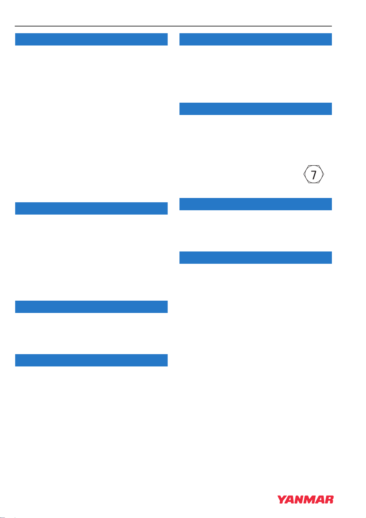
The tightening torque in the Standard Torque Chart
(see General Service Information section) should
be applied only to the bolts with a “7” head. (JIS
strength classification: 7T)
• Apply 60 % torque to bolts that are
not listed.
• Apply 80 % torque when tightened to
aluminum alloy.
If any indicator fails to illuminate when the key
switch is in the ON position, see your authorized
YANMAR industrial engine dealer or distributor for
service before operating the engine.
• Failure to comply may impair the engine’s safety
and performance characteristics and shorten the
engine’s life. Any alterations to this engine may
affect the warranty coverage of your engine. See
YANMAR Limited Warranty in Warranty Section.
Protect the air cleaner, turbocharger (if equipped)
and electric components from damage when you
use steam or high-pressure water to clean the
engine.
Never use high-pressure water or compressed air
at greater than 28 PSI (193 kPa ; 19686 mmAq) or a
wire brush to clean the radiator fins. Radiator fins
damage easily.
Establish a periodic maintenance plan according to
the engine application and make sure you perform
the required periodic maintenance at the intervals
indicated. Failure to follow these guidelines will
impair the engine’s safety and performance
characteristics, shorten the engine’s life and may
affect the warranty coverage on your engine.
See YANMAR Limited Warranty in Warranty
Section.
Consult your authorized YANMAR dealer or
distributor for assistance when checking items
marked with a
.
3-12
3TNV88F Service Manual
Page 27

Safety Precautions
NOTICE
NOTICE
NOTICE
NOTICE
NOTICE
NOTICE
NOTICE
NOTICE
NOTICE
NOTICE
NOTICE
NOTICE
NOTICE
SAFETY
If the fuel filter/water separator is positioned higher
than the fuel level in the fuel tank, water may not
drip out when the fuel filter/water separator drain
cock is opened. If this happens, turn the air vent
screw on the top of the fuel filter/water separ ator 2 3 turns counterclockwise.
Be sure to tighten the air vent screw a fter the w ater
has drained out.
• When the engine is operated in dusty conditions,
clean the air cleaner element more frequently.
• Never operate the engine with the air cleaner
element(s) removed. This may allow foreign
material to enter the engine and damage it.
The maximum air intake restriction, in terms of
differential pressure measurement, must not
exceed 0.90 PSI (6.23 kPa; 635 mmAq). Clean or
replace the air cleaner element if the air intake
restriction exceeds the above mentioned value.
Do not loosen or remove the f our bolts retaining the
fuel injection pump drive gear to the fuel injection
pump hub. Do not disassemble the fuel injection
pump drive gear from the hub . Correct fuel injection
timing will be very difficult or impossible to achieve.
The starter motor can be damaged if operated
continuously longer than 10 seconds while
performing the no-load test.
Do not short-circuit the charging system between
alternator terminals IG and L. Damage to the
alternator will result.
Do not connect a load between alternator terminals
L and E. Damage to the alternator will result.
Do not remove the positive (+) battery cable from
alternator terminal B while the engine is operating.
Damage to the alternator will result.
It is important to perform daily checks.
Periodic maintenance prevents unexpected
downtime, reduces the number of accidents due to
poor machine performance and helps extend the
life of the engine.
If the oil pump must be replaced, replace it as an
assembly only. Do not replace individual
components.
Do not turn the battery switch OFF while the engine
is operating. Damage to the alternator will result.
Do not operate the engine if the alternator is
producing unusual sounds. Damage to the
alternator will result.
If the engine coolant pump must be replaced,
replace the engine coolant pump as an assembly
only. Do not attempt to repair the engine coolant
pump or replace individual components.
3TNV88F Service Manual
3-13
Page 28

SAFETY
NOTICE
NOTICE
NOTICE
NOTICE
NOTICE
NOTICE
NOTICE
NOTICE
NOTICE
NOTICE
NOTICE
NOTICE
Safety Precautions
Use a new special O-ring between the engine
coolant pump and the joint. Be sure to use the
special O-ring for each engine model. Although the
O-ring dimensions are the same as a commercially
available O-ring, the material is different.
Remove or install the high-pressure fuel injection
lines as an assembly whenever possible.
Disassembling the high-pressure fuel injection lines
from the retainers or bending any of the fuel lines
will make it difficult to reinstall the fuel lines.
After marking the position of the pump drive gear,
do not rotate the engine crankshaft. Rotating the
crankshaft will cause the fuel injection pump to
become misaligned.
Do not use a high-pressure wash directly on the
alternator. Water will damage the alternator and
result in inadequate charging.
Do not reverse the positive (+) and negative (-)
ends of the battery cable. The alternator diode and
stator coil will be damaged.
Agricultural or other chemicals, especially those
with a high sulfur content, can adhere to the IC
regulator. This will corrode the co nductor and result
in battery over-charging (boiling) and charging
malfunctions. Consult YANMAR before using the
equipment in such an environment or the warranty
is voided.
Make sure that the combined total resistance of the
battery cable in both directions between the starter
motor and the battery is within the value indicated
on the wiring diagram. The starter motor will
malfunction or break down if the resistance is
higher than the specified value.
The starter motor is water-proofed according to JIS
D 0203, R2 which protects the motor from rain or
general cleaning. Do not use high-pressure wash
or submerse the starter motor in water.
Use a specialized battery charger to recharge a
battery with a voltage of 8 volts or less. Booster
starting a batter y with a voltage of 8 volts or less
will generate an abnormally high voltage and
destroy electrical equipment.
When the battery indicator goes out, it should not
come on again. The battery indicator only comes
on during operation if the alternator fails. However,
if an LED is used in the battery indicator, the LED
will shine faintly during normal operation.
Using a non-specified V-belt will cause inadequate
charging and shorten the belt life. Use the specified
belt.
Make sure that the combined total resistance of the
battery cable in both directions between the starter
motor and the battery is within the value indicated
in the Battery Cable Resistance chart in the Electric
Wiring Section of this manual. The starter motor will
malfunction and fail if the resistance is higher than
the specified value.
3-14
3TNV88F Service Manual
Page 29

Safety Precautions
NOTICE
NOTICE
NOTICE
NOTICE
NOTICE
NOTICE
NOTICE
NOTICE
NOTICE
NOTICE
NOTICE
SAFETY
Removing the battery cables or the battery while
the engine is operating may cause damage to the
current limiter depending on the electrical
equipment being used. This situation could cause
loss of control of output voltage. The continuous
high voltage of 23 - 24 volts (for 5000 min
dynamo) will damage the current limiter and other
electrical equipment.
Reversing the battery cable connections at the
battery or on the engine will destroy the SCR diode
in the current limiter. This will cause the charging
system to malfunction and may cause damage to
the electrical harnesses.
Avoid damage to the turbocharger or the engine.
Do not spray blower wash fluid or water too quickly.
Use short strokes from a spray bottle to inject
blower wash fluid or water into the turbocharger.
Spraying too much wash fluid or water, or spraying
too quickly will damage the turbocharger.
-1
(rpm)
• Never attempt to modify the engine’s design or
safety features such as defeating the engine
speed limit control or the diesel fuel injection
quantity control.
• Modifications may impair the engine’s safety and
performance characteristics and shorten the
engine’s life. Any alterations to this engine may
void its warranty. Be sure to use YANMAR
genuine replacement parts.
Identify all parts and their location using an
appropriate method. It is important that all parts are
returned to the same position during the
reassembly process.
Each pressure adjusting shim removed or added
changes the pressure threshold by approximately
275 PSI (1.9 MPa, 19 kgf/cm
shims increases the threshold pressure. Removing
adjusting shims reduces the pressure threshold.
2
). Adding adjusting
Do not allow any material to fall into the oil lines or
the oil inlet and outlet ports of the turbocharger.
If the waste valve does not meet specifications,
replace the turbocharger or have it repaired by a
qualified repair facility.
Do not rotate the crankshaft with the injection pump
removed.
Keep the piston pin parts, piston assemblies, and
connecting rod assemblies together to be returned
to the same position during the reassembly
process. Label the parts using an appropriate
method.
Do not allow the honing tool to operate in one
position for any length of time. Damage to the
cylinder wall will occur. Keep the tool in constant
up-and-down motion.
3TNV88F Service Manual
3-15
Page 30

SAFETY
NOTICE
NOTICE
NOTICE
NOTICE
NOTICE
NOTICE
NOTICE
NOTICE
NOTICE
Safety Precautions
Any part which is found defective as a result of
inspection or any part whose measured value does
not satisfy the standard or limit must be replaced.
Any part determined to not meet the service
standard or limit before the next service, as
determined from the state of current rate of wear,
should be replaced even though the part currently
meets the service standard limit.
• Never remove or attempt to remove the tamperproof devices from the full-load fuel adjusting
screw or the high-speed throttle limit scre w on the
fuel injection pump and governor assembly.
These adjustments have been made at the
factory to meet all applicable emissions
regulations and then sealed.
• Never attempt to make any adjustments to these
sealed adjustment screws. If adjustments are
required, they can be made only by a qualified
fuel injection shop that will ensure the injection
pump continues to meet all applicable emissions
regulations and then replace the tamper-proof
seals.
Shut down the engine if the fault indicator comes
on.
Continuing running the engine with the fault
indicator being on may result in a serious
malfunction of or damage to the engine, and will
void the engine warranty.
Do not energize the starter for a period of longer
than 15 seconds.
Take a pause of at least 30 seconds between
energization of the starter.
Otherwise the starter could suffer damage.
• High-pressure washing not recommended.
• Avoid using high-pressure washing for electronic
or electric devices installed in, on or around the
engine, including the E-ECU, relays and harness
couplers.
Otherwise such devices ma y suffer malf unction due
to water ingress into them.
• Tampering with or removing these devices may
void the “YANMAR Limited Warranty.”
Never use a steel wire brush to clean fuel injectors .
Damage to the nozzle and other components is
likely to result.
Allow the engine to warm-up for at least five
minutes and the idle speed of the engine to return
to normal before engaging the transmission or any
PTOs. Engaging the transmission or PTO at an
elevated engine speed could result in an
unexpected movement of the equipment.
Always check the battery for proper charge.
Otherwise the electronically controlled engines ma y
fail to start.
3-16
3TNV88F Service Manual
Page 31

Safety Precautions
NOTICE
NOTICE
SAFETY
• Do not plug or unplug the E-ECU for a period of
at least 6 seconds after power to the unit has
been turned on or off.
• Do not touch connector pins of the E-ECU with
bare hands.
Doing so may result in corrosion o f the connector
pins and/or damage to the internal circuits of the
E-ECU due to static electricity.
• Do not force a measuring probe into the female
coupler.
Doing so may cause contact failure of the
connector pins, resulting in malfunction of the EECU.
• Take care to prevent water from entering the
couplers when plugging or unplugging the
connector.
Water inside the couplers may cause corrosion,
resulting in malfunction of the E-ECU.
• Avoid plugging/unplugging the connector more
than approx. 10 times.
Frequent plugging/unplugging of the connector
may cause contact failure of the connector pins,
resulting in malfunction of the E-ECU.
• Never permit anyone to operate the
engine or driven machine without
proper training.
• Read and understand this Operation Manual
before you operate or service the machine to
ensure that you follow safe operating practices
and maintenance procedures.
• Machine safety signs and labels are additional
reminders for safe operating and maintenance
techniques.
• See your authorized YANMAR industrial engine
dealer or distributor for additional training.
• Do not use the E-ECU that has ever suff ered drop
impact.
3TNV88F Service Manual
3-17
Page 32

SAFETY
Safety Precautions
This Page Intentionally Left Blank
3-18
3TNV88F Service Manual
Page 33

3TNV88F Service Manual
Section 4
GENERAL SERVICE
INFORMATION
Component Identification................................................................. 4-3
Location of Labels........................................................................... 4-4
Engine Nameplate (Typical)...................................................... 4-4
Emission Control Regulations......................................................... 4-5
EPA/ARB Regulations - USA Only............................................ 4-5
Emission Control Labels.................................................................. 4-5
EPA/CARB Labels (Typical)...................................................... 4-5
Engine Family.................................................................................. 4-6
Page
Function of Major Engine Components........................................... 4-7
Main Electronic Control Components and Features........................ 4-8
Function of Cooling System Components..................................... 4-10
Diesel Fuel .................................................................................... 4-11
Diesel Fuel Specifications ....................................................... 4-11
Filling The Fuel Tank............................................................... 4-15
Priming the Fuel System ......................................................... 4-16
Engine Oil...................................................................................... 4-17
Engine Oil Specifications ........................................................ 4-17
Engine Oil Viscosity................................................................. 4-17
Checking Engine Oil................................................................ 4-18
Adding Engine Oil.................................................................... 4-18
Engine Oil Capacity (Typical).................................................. 4-18
Engine Coolant.............................................................................. 4-19
Engine Coolant Specifications................................................. 4-20
Filling Radiator with Engine Coolant........................................ 4-20
Engine Coolant Capacity (Typical).......................................... 4-21
3TNV88F Service Manual
4-1
Page 34

GENERAL SERVICE INFORMATION
Specifications................................................................................. 4-22
Description of Model Number................................................... 4-22
Engine General Specifications................................................. 4-22
Principal Engine Specifications...................................................... 4-23
Engine Service Standards.............................................................. 4-24
Tightening Torques for Standard Bolts and Nuts........................... 4-25
Abbreviations and Symbols............................................................ 4-27
Symbols.................................................................................... 4-27
Unit Conversions............................................................................ 4-28
4-2
3TNV88F Service Manual
Page 35

Component Identification
045002-00X00
456789101112
3
4
5
19202122
GENERAL SERVICE INFORMATION
COMPONENT IDENTIFICATION
Figure 4-1 shows where the major engine components are located.
3TNV88F
231
1
1
1
16 17 18
1 –Lifting eye (flywheel end)
2 –Lifting eye (engine cooling fan end)
3 –Engine coolant pump
4 –Engine cooling fan
5 –Crankshaft V-pulley
6–V-belt
7 –Side filler port (engine oil)
8 –Engine oil cooler
9 –Fuel injection pump
10–Engine oil filter
11– Intake manifold
12–Dipstick (engine oil)
13–Fuel filter
14–Fuel return to fuel tank
15–Fuel inlet
16–Top filler port (engine oil)
17– Rocker arm cover
18–EGR valve
19–Flywheel
20–Starter moto r
21–Exhaust manifold
22– Alternator
Figure 4-1
*: Engine oil drain plug locati on may vary based on oil pan opti ons.
3TNV88F Service Manual
4-3
Page 36

GENERAL SERVICE INFORMATION
045044-00X01
MODEL
DISPLACEMENT
ENGINE NO.
MADE IN JAPAN
043923-00X00
Location of Labels
LOCATION OF LABELS
Figure 4-2 shows the location of regulatory and safety labels on YANMAR TNV series direct injection
model engine.
12
Figure 4-2
■ Location of labels/nameplates on direct injection model engines
Model Engine nameplate EPA/ARB certification label
3TNV88F
On the top of the locker arm cover (cooling
fan end) Figure 4-2, (2)
On the top of the locker arm cover
(flywheel end) Figure 4-2, (1)
Engine Nameplate (Typical)
4-4
Figure 4-3
3TNV88F Service Manual
Page 37

Emission Control Regulations
REFER TO OWNER'S MANUAL FOR MAINTENANCE SPECIFICATIONS AND
ADJUSTMENTS.
EMISSION CONTROL INFORMATION
ULTRA LOW SULFUR FUEL ONLY
THIS ENGINE COMPLIES WITH U.S. EPA REGULATIONS FOR M. Y.
NONROAD AND STATIONARY DIESEL ENGINES.
ENGINE FAMILY : DISPLACEMENT : LITERS
ENGINE MODEL : E. C. S. :
FUEL RATE :
MM3/STROKE @ kW /
RPM
PM : 0.30g / kWh
REFER TO OWNER'S MANUAL FOR MAINTENANCE SPECIFICATIONS AND
ADJUSTMENTS.
EMISSION CONTROL INFORMATION
ENGINE FAMILY : DISPLACEMENT : LITERS
ENGINE MODEL : E. C. S. :
FUEL RATE :
MM3/STROKE @ kW /
RPM
THIS ENGINE COMPLIES WITH U. S. EPA AND CALIFORNIA REGULATIONS
FOR M. Y. NONROAD AND STATIONARY / OFF-ROAD DIESEL ENGINES.
ULTRA LOW SULFUR FUEL ONLY
GENERAL SERVICE INFORMATION
EMISSION CONTROL
REGULATIONS
EPA/ARB Regulations - USA Only
YANMAR TNV engines meet Environmental
Protection Agency (EPA) (U. S. Federal) emission
control standards as well as the California Air
Resources Board (ARB, California) regulations.
Only engines that conform to ARB regulations can
be sold in the State of California.
Refer to the specific EPA/ARB installation
(page 5-4) and maintenance (page 5-4) in the
Periodic Maintenance Schedule section of this
manual. Also refer to theEmission System W arranty
on page 2-6.
EMISSION CONTROL LABELS
Since emission control regulations are being issued
on a global basis, it is necessary to identify which
regulations a particular engine complies with. We
have listed several different types of labels you
might find on your engine.
EPA/CARB Labels (Typical)
■ EPA
■ EPA and CARB
3TNV88F Service Manual
4-5
Page 38

GENERAL SERVICE INFORMATION
ENGINE FAMILY
The EPA/ARB labels have an Engine Family field.
The following is an explanation of the Engine Family designation:
CYDXL1.64M 3 N
Method of air aspiration
Number of cylinders
Engine speed specifications
Displacement (l)
Non-road/off-road engine
YANMAR diesel
Model year
C: 2012
D: 2013
Engine Family
E: 2014
F: 2015
4-6
3TNV88F Service Manual
Page 39

Function of Major Engine Components
GENERAL SERVICE INFORMATION
FUNCTION OF MAJOR ENGINE COMPONENTS
Components Functions
Air cleaner The air cleaner prevents airborne contaminants from entering the engine.
Since the air cleaner is application specific, it must be carefully selected by
an application engineer. It is not part of the basic engine packag e as shipped
from the YANMAR factory. Periodic replacement of the air cleaner filter
element is necessary. See the Periodic Maintenance Sched ule on page 5-5
for the replacement frequency.
Alternator The alternator is driven by a V-belt which is powered by the crankshaft V-
pulley. The alternator supplies electricity to the engine systems and charges
the battery while the engine is running.
Dipstick (engine oil) The engine oil dipstick is used to determine the amount of engine oil in the
crankcase.
Electric fuel pump The electric fuel pump makes sure there is a constant supply of diesel fuel
to the fuel injection pump. The electric fuel pump is electro-magnetic and
runs on 12 V DC. It must be installed on every application. This is standard
equipment with every engine.
Engine oil filter The engine oil filter removes contaminants and sediment s from the engine
oil. Periodic replacement of the engine oil filter is necessary. See the
Periodic Maintenance Schedule on page 5-5 for the replacement frequency.
Engine oil cooler
(if equipped)
Fuel filter The fuel filter removes contaminants and sediments from the diesel fuel.
Fuel filter/water separator The fuel filter/water separator removes co ntaminants, sediments a nd water
Fuel tank The fuel tank is a reservoir that holds diesel fuel. When the fuel leaves the
Side and top filler port (engine oil) You can fill the crankcase with engine oil from either the side or the top filler
Starter motor The starter motor is powered by the battery. When you turn the key switch
The engine oil cooler helps to keep the engine oil cool. Engine coolant from
the cooling system is circulated through an adapter at the base of the engine
oil filter assembly and then returned to the coolant pump inlet.
Periodic replacement of the fuel filter is necessary. See the Periodic
Maintenance Schedule on page 5-5 for the replacement frequency.
Please note that the word “diesel” is implied throughout this manual
when the word “fuel” is used.
from the diesel fuel going to the fuel filter. This is a required component of
the fuel system. This is standard equipment with every engine. The
separator is installed between the fuel tank and the electric fuel pump.
Periodically drain the water from the fuel filter/water separator.
fuel tank it goes to the fuel filter /water separator. Next the fuel is pump ed to
the fuel filter by the electric fuel pump. Then the fuel goes to the fu el injection
pump. Since the fuel is used to keep the fuel injection pump cool and
lubricated, more fuel than necessary enters the injection pump. When the
injection pump pressure reaches a preset value, a relief valve allows the
excess fuel to be returned back to the fuel tank. The fuel tank is a required
engine component.
port depending upon which one is most convenient.
in the operator’s console to the START position, the start er mot or engag es
with the ring gear installed on the flywheel and starts t he flywheel in motion.
3TNV88F Service Manual
4-7
Page 40

GENERAL SERVICE INFORMATION
Main Electronic Control Components and Features
MAIN ELECTRONIC CONTROL COMPONENTS AND FEATURES
Component/feature Description
Engine controller (E-ECU) Adjusts the rack position of the fuel injection pump depending
on the speed command signal from t he accelerator sensor, thus
regulating the engine speed and power. The engine controller
also regulates the opening of the EGR valve dep en ding on t he
engine speed and power. It serves as the master station for the
following components/control features.
Electronic governor (Eco-governor) Consists of the engine speed sensor, rack actuator, etc., and is
directly connected to the fuel injection pump in order to regulate
the rack position of the fuel injection pump depending on the
signals communicated with the E-ECU.
Fuel injection pump (for Eco-governor) Is of single plunger type and equipped with a CSD solenoid
valve that allows the fuel injection timing to advance and the
injection quantity to increase, thereby improving the cold sta rt
performance of the engine.
EGR valve Controls the exhaust gas recirculation flow rate depending on
the engine speed/load signals from the E-ECU. It is installed on
the top of the exhaust manifold.
Accelerator sensor Unlike mechanical governors, the Eco-governor has no
governor lever. The accelerator sensor ser ves as t he gover nor
lever to provide the speed command signal (voltage signal) to
the E-ECU for engine speed control. It is installed in the
operator cabin of the driven mach ine . Constant sp eed e ng ines
for e.g. generator use do not require accelerator sensors
because the engine speed can be shifted via a switch on the
operator's console.
Optional CAN communication capability is available as an option.
Fault indicator Is installed on the operator’s console. If a fault occurs in th e E-
ECU or Eco-governor, the fault indicator fl ashes alerting the
operator to a fault. The number of flashe s and/or the flashing
pattern vary depending on the type or source of the fault,
Optional
Engine diagnosis tool Allows the operator to troubleshoot the cause of a problem
Option for service
Engine coolant temperature sensor Allows the CSD to be controlled in en gine col d-st art conditio ns.
Glow plugs Optional When the key switch is turned to the ON position , the glow plugs
enabling quick-fix.
based on detailed information regarding the prob lem occurring
in the E-ECU or Eco-governor. This tool can also be used for
data maintenance tasks including programming and mapping.
See Failure Diagnosis on page 14-1.
are energized for up to 15 seconds. The duration of
energization depends on the engine coolant temperature. The
HEAT indicator is on during energization. When the indicator
goes out, turn the key switch to the START position to start the
engine.
4-8
3TNV88F Service Manual
Page 41

Main Electronic Control Components and Features
GENERAL SERVICE INFORMATION
Component/feature Description
Droop control Standard with VM series Reduces the engine speed by a certain percentage from no
load to full (rated) load in steady state oper ation. The same
percentage droop is maintained even when the load increases
at any no-load speed.
Isochronous control Standard with CL series
Optional with VM series
Offers a constant engine speed from no load to full load. The
engine speed does not decrease even when the load increase s
at any no-load speed.
Low-idling speed up
Increases the low-idling speed to up to 1000 min
-1
(rpm)
depending on the engine coolant temperature. When the
coolant temperature reaches a predeterm ined value, this
feature returns the engine speed to the normal low idle setting,
thus reducing the warm-up time.
High-idling speed
down
Optional Decreases the high-idling speed depending on the engine
coolant temperature. When the coolant temperature falls to a
predetermined value, this feature returns the engine speed to
the normal high idle setting, thus minimizing the emission of
white smoke at low temperatures.
Auto deceleration Optional Brings the running engine in low idle mode automat ically when
the accelerator pedal is not opera ted for a predetermined period
of time. When the pedal is operated, i.e., the acce lerator sensor
is activated, the low idle mode is cancelled.
3TNV88F Service Manual
4-9
Page 42

GENERAL SERVICE INFORMATION
Function of Cooling System Components
FUNCTION OF COOLING SYSTEM COMPONENTS
Components Functions
Cooling system The TNV engine is liquid-cooled by means of a cooling system. The cooling
system consists of a radiator, radiator cap, engine cooling fan, engine
coolant pump, thermostat, and reserve tank.
Note that all cooling system components are required for proper
engine operation. Since some of the components are application
specific, they must be carefully selected by an application engineer.
The application specific ite ms are not part of the basic engine package
as shipped from the YANMAR factory.
• Engine cooling fan The engine cooling fan is driven by a V-b elt which is powered by the
crankshaft V-pulley. The purpose of the engine cooling fan is to circula te air
through the radiator.
• Engine coolant pump The engine coolant pump circulates the engine coolant through t he cylinder
block and the cylinder head and returns the engine coolant to the radiator.
• Radiator The radiator acts as a heat exchanger. As the engine coolant circulates
through the cylinder block it absorbs heat. Th e heat in the engine coolant is
dissipated in the radiator. As the engine cooling fan circulates air through
the radiator, the heat is transferred to the air.
• Radiator cap The radiator cap controls the cooling system pre ssure. The co oling syst em
is pressurized to raise the boiling point of the en gine coolant. As the engine
coolant temperature rises, the system pressure and the coolant volume
increases. When the pressure reaches a preset value, the release valve in
the radiator cap opens and the excess engine coo lant flows into the reserve
tank. As the engine coolant temperature is reduced, the system pressure
and volume is reduced and the vacuum valve in the radiator cap opens
allowing the engine coolant to flow from the reserve tank back into the
radiator.
• Reserve tank The reserve tank contains the overflow of engin e coolant fro m the rad iator .
If you need to add engine coolant to the system, add it to the reserve tank;
not the radiator.
• Thermostat A thermostat is placed in the cooling system to prevent the engine coolant
from circulating into the radiator until the engine coolant temperature
reaches a preset temperature. When the engine is cold, no engine coolant
flows through the radiator. Once the engine rea ches its operating
temperature, the thermostat opens and al lows the engine coolant to flow
through the radiator. By letting the engine warm up as quickly as possible,
the thermostat reduces engine wear, depo sits and emissions.
4-10
3TNV88F Service Manual
Page 43

Diesel Fuel
GENERAL SERVICE INFORMATION
DIESEL FUEL
Diesel Fuel Specifications
Diesel fuel should comply with the following
specifications. The table lists several worldwide
specifications for diesel fuels.
Diesel fuel specification Location
ASTM D975
No. 1D S15
No. 2D S15
EN590:96 European Union
ISO 8217 DMX International
BS 2869-A1 or A2 United Kingdom
JIS K2204 Grade No. 2 Japan
KSM-2610 Korea
GB252 China
USA
■ Additional technical fuel requirements
• The fuel cetane number should be equal to 45 or
higher.
• The sulfur content must not exceed 0.5 % by
volume. Less than 0.05 % is preferred.
For electronically controlled engines 3TNV88F
(EGR system equipped engine), it is mandatory
to use fuel that does not contain 0.1 % or more
sulfur content.
In general, using a high sulfur fuel may
possible result in corrosion inside the
cylinder. Especially in U.S.A. and Canada,
Ultra Low Sulfur fuel must be used.
• Bio-Diesel fuels. See Bio-diesel fuels on
page 4-12.
• Never mix kerosene, used engine oil, or residual
fuels with the diesel fuel.
• The water and sediment in the fuel should not
exceed 0.05 % by volume.
• Keep the fuel tank and fuel-handling equipment
clean at all times.
• Poor quality fuel can reduce engine performance
and/or cause engine damage.
• Fuel additives are not recommended. Some fuel
additives may cause poor engine performance.
Consult your YANMAR representative for more
information.
• The ash content must not exceed 0.01 % by
volume.
• The carbon residue content must not exceed 0.35
% by volume. Less than 0.1 % is preferred.
• The total aromatics content should not ex ceed 35
% by volume. Less than 30 % is preferred.
• The PAH (Polycyclic Aromatic Hydrocarbons)
content should be below 10 % by volume.
• The metal content of Na, Mg, Si, and Al should be
equal to or lower than 1 mass ppm. (Test analysis
method JPI-5S-44-95)
• Lubricity: The wear mark of WS1.4 should be
Max. 0.018 in. (460 µm) at HFRR test.
3TNV88F Service Manual
4-11
Page 44

GENERAL SERVICE INFORMATION
Diesel Fuel
■ Bio-diesel fuels
General description of biodiesel
1. Biodiesel is a renewable, oxygenated fuel made
from agricultural and renewable resources such
as soybeans or rapeseeds. Biodiesel is a fuel
comprised of methyl or ethyl ester-based
oxygenates of long chain fatty acids derived
from the transesterification of vegetable oils,
animal fats, and cooking oils. It contains no
petroleum-based diesel fuel but can be blended
at any level with petroleum-based diesel fuel. In
case it is not blended with petroleum-based
diesel fuel such biodiesel is referred to as
“B 100”, which means that it consists of 100 %
(pure) biodiesel. However, most common
biodiesel is blended with conventional
(petroleum-based) diesel fuel. The percentage
of the blend can be identified by its name. The
most common blends are “B 7” (consisting of 7
% bio- diesel and 93 % conventional petroleumbased diesel fuel) and “B 20” (a blend of 20 %
biodiesel and 80 % conventional diesel). Raw
pressed vegetable oils are not considered to be
biodiesel.
2. Advantages of biodiesel:
• Biodiesel produces less visible smoke and a
lower amount of particulate matter .
• Biodiesel is biodegradable and nonto xic.
• Biodiesel is safer than conv entional diesel fuel
because of its higher flash point.
Following the increased interest in the reduction
of emissions and the reduction of the use of
petroleum distillate based fuels; many
governments and regulating bodies e ncourage
the use of biodiesel.
• Biodiesel can accelerate the oxidation of
Aluminum, Brass, Bronze , Copper and Zinc.
• Biodiesel damages, and finally seeps through
certain seals, gaskets, hoses, glues and
plastics.
• Certain natural rubbers, nitride and butyl
rubbers will become harder and more brittle as
degradation proceeds when used with
biodiesel.
• Biodiesel typically creates deposits in the
engines.
• Due to its natural characteristic, biodiesel will
decrease the engine output by appro ximately 2
percent (in case of B 20) comparing to
conventional (p etroleum-based) diesel fuel.
• The fuel consumption ratio will increase by
approximately 3 percent (in case o f B 20)
comparing to conventional diesel fuel.
Approved engines
All of the following engine series of YANMAR can
be operated with biodiesel with concentrations up
to B 20. In case of using biodiesel fuel up to
B 7 concentrations, no special preparations etc.
have to be made and the original operating
conditions and service intervals as stated in the
operating manuals apply. In case of running below
indicated engines with biodiesel concentrations
above B 8 up to B 20, the required operating
conditions (see below Conditions for the operation
with biodiesel (B 8 through B 20)) have to be
observed.
Other than the following listed engines cannot be
run with biodiesel:
• 3TNV88F series
3. Disadvantages of biodiesel:
Concentrations that are higher than 7 % of
biodiesel (higher than B 7) can hav e an adverse
affect on the engine’ s perf ormance, its integrity
and/ or durability . The risk of proble ms occurring
in the engine increases as the lev el of biodiesel
blend increases. The f ollowing negativ e affects
are ex emplary and typical for the usage of high
concentrated biodiesel blends:
4-12
3TNV88F Service Manual
Page 45

Diesel Fuel
GENERAL SERVICE INFORMATION
Approved fuel
In case of using biodiesel (only concentrations up
to B 20) such fuel should comply with the below
recommended standards. However, raw pressed
vegetable oils are not considered to be biodiesel
and are not acceptable for use as fuel in any
concentration in YANMAR engines.
1. EN14214 (European standard) and/or ASTM D6751 (American standard).
2. All applicable engines can be operated with
biodiesel fuel up to B 20 (20 % bio-fuel blend)
as a maximum concentration.
(For your information: In Japan, the legally
allowed maximum concentration for on-road
applications is B 5.)
Conditions for the operation with biodiesel
(B 8 through B 20)
When operating your applicable YANMAR engine
with biodiesel blends concentrated above B 5, we
seriously recommend observing the following
operation, service and maintenance conditions:
1. The original service interval of the below stated
services as indicated in the respective
YANMAR engine standard operation manual,
the application manual and the service manual
should be halved (please refer to your own
manuals for the each service interval):
• Replacement interval of engine oil filter, engine
oil and the fuel filter.
• Cleaning interval of the water separator
4. Please use only biodiesel fuel that is
appropriate to the intended operation
environment of the engines. This especially
applies if the operating ambient temperature
falls below 0 degree centigrade.
5. Operation with biodiesel requires daily
maintenance as follows:
• Please daily check the engine oil le vel. If the oil
level rises abov e the oil le vel of the pre vious
day, the engine oil needs to be immediately
replaced.
• Please daily check the water le vel of the water
separator . If the water le vel rises abov e the
“max” indicator, an immediate drain of the
water separator is required.
6. Biodiesel blends up to B 20 can only be used
for a limited time of up to 3 months of the date
of biodiesel manufacture. Therefore biodiesel
needs to be used at latest within 2 months from
the time of filling the tank or within 3 months
from the time of production by the fuel supplier,
whichever comes first.
7. Before a long-term storage without operating
the engine, the biodiesel needs to be drained
out completely and the engine has to be run for
5 hours with conventional diesel fuel as
indicated in your operation manual.
• Drain interval of the fuel tank.
2. It is required to inspect, clean and adjust the
fuel injector every 1000 operating hours.
3. Replacement of the following parts before using
the recommended biodiesel:
• Fuel hose
• If not already installed, a water separator
needs to be built in
• O-ring of fuel filter
• O-ring of water separator
Please refer to the attached list of exchange
parts for details.
3TNV88F Service Manual
4-13
Page 46

GENERAL SERVICE INFORMATION
033042-00X
C 24326-000750 (G75)
D 24316-000160 (P16)
E 24316-000070 (P7)
■ KIT parts list for B 20 (TNV DI engines)
No. (1)
Fuel oil tank / - Fuel oil tank
Fuel feed pump
- Fuel oil filter
Fuel oil filter
- Fuel injection pump
Fuel injection pump
- Fuel oil filter
Cap, fuel injection nozzle
Fuel injection nozzle
-Fuel injection nozzle
Fuel injection nozzle
- Fuel injection pump
Fuel oil filter
Water separator
Length 2000
Part No. 129946-59050
Part name FO-T CMP
Number 2
No. (4)
Length 1000
Part No. 129946-59040
Part name FO-T CMP
Number 1
No. (5)
Length 220
Part No. 129236-59000
Part name FO-T CMP
Number 1
No. (7)
Length 300
Part No. 129236-59010
Part name FO-T CMP
Number 1
Part No.
Part name
Number
No. (13)
Length 115
Part No. 129486-59581
Part name FO-T CMP
Number 2
No. (17)
Length Formed pipe
Part No. 129636-59561
Part name FO-T CMP
Number 1
KIT-V384BGS-BI
3TNV84(T),88
D29283-59260
119593-59581
124060-77680
CAP
CLIP
1
1
(Because of cartridge type)
G75 : 24326-000750 --> C
P16 : 24316-000160 --> D
P7 : 24316-000070 --> E
G65 : 24326-000650 --> C (Need only for TAIYO-GIKEN)
Need to change only O-ring.
No need
Diesel Fuel
4-14
D
C
E
3TNV88F Service Manual
Page 47

Diesel Fuel
DANGER
NOTICE
Filling The Fuel Tank
Fire and Explosion Hazard!
• Diesel fuel is flammable and
explosive under certain
conditions.
• Only fill the fuel tank with diesel fuel. Filling
the fuel tank with gasoline may result in a fire
and will damage the engine.
GENERAL SERVICE INFORMATION
• Only use diesel fuels recommended by YANMAR
for the best engine performance, to prevent
engine damage and to comply with EPA/ARB
warranty requirements.
• Only use clean diesel fuel.
• Never remove the primary strainer (if equipped)
from the fuel tank filler port. If removed, dirt and
debris could get into the fuel system causing it to
clog.
• Never refuel with the engine running.
• Wipe up all spills immediately.
• Keep sparks, open flames or any other form of
ignition (match, cigarette, static electric
source) well away when refueling.
• Never overfill the fuel tank.
• Fill the fuel tank. Store any containers
containing fuel in a well-ventilated area, away
from any combustibles or sources of ignition.
• Be sure to place the diesel fuel container on
the ground when transferring the diesel fuel
from the pump to the container. Hold the hose
nozzle firmly against the side of the container
while filling it. This prevents static electricity
buildup which could cause sparks and ignite
fuel vapors.
• Never place diesel fuel or other flammable
material such as oil, hay or dried grass close
to the engine during engine operation or
shortly after shutdown.
Note that a typical fuel tank is shown. The fuel tank
on your equipment may be different.
1. Clean the area around the fuel cap
(Figure 4-4, (1)).
2. Remove the fuel cap (Figure 4-4, (1)) from the
fuel tank (Figure 4-4, (2)).
3. Observe the fuel level sight gauge
(Figure 4-4, (3)) and stop fueling when the
gauge shows the fuel tank is full. Neve r overfill
the fuel tank.
4. Replace the fuel cap (Figure 4-4, (1)) and hand
tighten. Over-tightening the fuel cap will
damage it.
1
2
• Before you operate the engine, check for fuel
leaks. Replace rubberized fuel hoses every
two years or every 2000 hours of engine
operation, whichever comes first, even if the
engine has been out of service. Rubberized
fuel lines tend to dry out and become brittle
after two years or 2000 hours of engine
operation, whichever comes first.
• Failure to comply will result in death or
serious injury.
3TNV88F Service Manual
3
K0000002A
Figure 4-4
4-15
Page 48

GENERAL SERVICE INFORMATION
Priming the Fuel System
The fuel system needs to be primed under certain
conditions:
• Before starting the engine for the first time.
• After running out of fuel and fuel has been added
to the fuel tank.
• After fuel system maintenance such as changing
the fuel filter and draining the fuel filter/water
separator, or replacing a fuel system component.
To prime the fuel system:
1. Turn the key to the ON position for 10 - 15
seconds. This will allow the electric fuel pump
to prime the fuel system.
2. Never use the starter motor to crank the engine
in order to prime the fuel system. This may
cause the starter motor to overheat and
damage the coils, pinion and/or ring gear.
Diesel Fuel
4-16
3TNV88F Service Manual
Page 49

Engine Oil
NOTICE
-30°C -20°C -10°C 0 10°C 20°C 30°C
SAE 5W-30
SAE 15W-40
SAE 20
SAE 30
SAE 10W-30
K0000005A05
40°C
GENERAL SERVICE INFORMATION
ENGINE OIL
• Only use the engine oil specified. Other engine
oils may affect warranty coverage, cause internal
engine components to seize and/or shorten
engine life.
• Prevent dirt and debris from contaminating the
engine oil. Carefully clean the oil cap/dipstick and
the surrounding area before you remove the cap.
• Never mix different types of engine oil. This may
adversely affect the lubricating properties of the
engine oil.
• Never overfill. Overfilling may result in white
exhaust smoke, engine overspeed or internal
damage.
Engine Oil Specifications
Note:
• Be sure the engine oil, engine oil storage
containers, and engine oil filling equipment are
free of sediment and water.
• Change the engine oil after the first 50 hours of
operation and then every 250 hours thereafter.
• Select the oil viscosity based on the ambient
temperature where the engine is being operated.
See the SAE service grade viscosity chart
(Figure 4-5).
• YANMAR does not recommend the use of engine
oil “additives”.
■ Additional technical engine oil
requirements:
The engine oil must be changed when the Total
Base Number (TBN) has been reduced to 1.0
mgKOH/g test method; JIS K-201-5.2-2 (HCI),
ASTM D4739 (HCI).
Use an engine oil that meets or exceeds the
following guidelines and classifications:
■ Service categories
• API service categories CF, CF-4 and CI-4
• ACEA service categories E-3, E-4, and E-5
• JASO service category DH-1
■ Definitions
• API classification (American Petroleum Institute)
• ACEA classification (Association des
Constructeurs Européens d’Automobilies)
• JASO (Japanese Automobile Standards
Organization)
Engine Oil Viscosity
Select the appropriate engine oil viscosity based on
the ambient temperature and use the SAE service
grade viscosity chart in Figure 4-5.
Figure 4-5
3TNV88F Service Manual
4-17
Page 50

GENERAL SERVICE INFORMATION
CAUTION
045046-00X02
2
4
5
1
4
3
Engine Oil
Checking Engine Oil
1. Make sure the engine is level.
2. Remove the dipstick (Figure 4-6, (1)) and wipe
it with clean cloth.
3. Fully reinsert the dipstick.
4. Remove the dipstick. The oil level should be
between the upper (Figure 4-6, (2)) and lower
(Figure 4-6, (3)) lines on the dipstick.
5. Fully reinsert the dipstick.
Adding Engine Oil
1. Make sure the engine is level.
2. Remove the oil cap (Figure 4-6, (4)).
3. Add the indicated amount of engine oil at the
top or the side engine oil filler port
(Figure 4-6, (5)).
4. Wait three minutes and check the oil level.
5. Add more oil if necessary.
6. Reinstall the oil cap (Figure 4-6, (4)) and
hand-tighten. Over-tightening may damage the
cap.
Engine Oil Capacity (Typical)
Note: These are the engine oil capacities
associated with a “deep standard” oil pan.
The oil capacity will vary dependant upon
which optional oil pan is used. Refer to the
operation manual provided by the driven
machine manufacturer for the actual engine
oil capacity of your machine.
The following are the engine oil capacities for
various YANMAR TNV engines.
Engine model
3TNV88F 7.1/4.1 qt (6.7/3.9 l)
upper limit/lower limit
Dipstick
To refuel the engine oil, refuel slowly after
removing the dipstick and both caps. If you
refuel rapidly, the oil intrusion to the intake
occurs through the PCV valve of the valve
Figure 4-6
cover. It will result in an oil hammer at engine
start, which may cause damage to the engine.
4-18
3TNV88F Service Manual
Page 51

Engine Coolant
DANGER
WARNING
CAUTION
NOTICE
ENGINE COOLANT
Scald Hazard!
• Never remove the radiator cap if
the engine is hot. Steam and hot
engine coolant will spurt out and
seriously burn you. Allow the
engine to cool down before you
attempt to remove the radiator
cap.
• Tighten the radiator cap securely after you
check the radiator. Steam can spurt out
during engine operation if the cap is loose.
• Always check the level of the engine coolant
by observing the reserve tank.
• Failure to comply will result in death or
serious injury.
GENERAL SERVICE INFORMATION
• Only use the engine coolant specified. Other
engine coolants may affect warranty coverage,
cause an internal buildup of rust and scale and/or
shorten engine life.
• Prevent dirt and debris from contaminating the
engine coolant. Carefully clean the radiator cap
and the surrounding area before you remove the
cap.
• Never mix diff eren t types of engine coo lants. This
may adversely affect the properties of the engine
coolant.
Burn Hazard!
• Wait until the engine cools before
you drain the engine coolant. Hot
engine coolant may splash and
burn you.
• Failure to comply could result in death or
serious injury.
Coolant Hazard!
• Wear eye protection
and rubber gloves
when you handle long
life or extended life
engine coolant. If
contact with the eyes
or skin should occur,
flush eyes and wash
immediately with
clean water.
• Failure to comply may result in minor or
moderate injury.
3TNV88F Service Manual
4-19
Page 52

GENERAL SERVICE INFORMATION
1
046370-00X00
Engine Coolant
Engine Coolant Specifications
Use a Long Life Coolant (LLC) or an Extended Life
Coolant (ELC) that meets or exceeds the following
guidelines and specifications:
■ Additional technical coolant specifications:
• ASTM D6210, D4985 (US)
• JIS K-2234 (Japan)
• SAE J814C, J1941, J1034 or J2036
(International)
■ Alternative engine coolant
If an Extended or Long Life Co olant is not av ailab le,
alternatively, you may use an ethylene glycol or
propylene glycol based conventional coolant
(green).
Note:
• Always use a mix of coolant and water.
Never use water only.
• Mix the coolant and water per the mixing
instructions on the coolant container.
• Water quality is important to coolant
performance. YANMAR recommends that soft,
distilled, or demineralized water be used to mix
with coolants.
Filling Radiator with Engine Coolant
Fill the radiator and reserve tank as follows. This
procedure is for filling the radiator for the first time
or refilling it after it is flushed. Note that a typical
radiator is illustrated (Figure 4-7).
2
5
3
6
4
1
1. Check to be sure the radiator drain plug is
installed and tightened or the drain cock
(Figure 4-7, (1)) is closed. Also make sure the
coolant drain plug (Figure 4-8, (1)) in the
cylinder block is closed.
FULL
LOW
Figure 4-7
K0000029A
• Never mix extended or long life coolants and
conventional (green) coolants.
• Never mix different types and/or colors of
extended life coolants.
• Replace the coolant every 1000 engine hours or
once a year.
Figure 4-8
2. Remove the radiator cap (Figure 4-7, (2)) by
turning it counter-clockwise about 1/3 of a turn.
4-20
3TNV88F Service Manual
Page 53

Engine Coolant
GENERAL SERVICE INFORMATION
3. Pour the engine coolant slowly into the radiator
until it is even with the lip of the engine coolant
filler port. Make sure that air bubbles do not
develop as you fill the radiator.
4. Reinstall the radiator cap (Figure 4-7, (2)).
Align the tabs on the back side of the radiator
cap with the notches on the engine coolant filler
port. Press down and turn the cap clockwise
about 1/3 of a turn.
5. Remove the cap on the reserve tank
(Figure 4-7, (3)), and fill it to the LOW (COLD)
mark (Figure 4-7, (4)) with engine coolant.
Reinstall the cap.
6. Check the hose (Figure 4-7, (5)) that connects
the reserve tank (Figure 4-7, (3)) to the
radiator. Be sure it is securely connected and
there are no cracks or damage. If the hose is
damaged, the engine coolant will leak out
instead of going into the reserve tank.
7. Run the engine until it is at operating
temperature. Check the level of engine coolant
in the reserve tank. When the engine is running
and the engine coolant is at normal
temperature, the coolant le vel in the tank should
be at the FULL (HOT) mark (Figure 4-7, (6)). If
the engine coolant is not at the FULL (HOT)
mark (Figure 4-7, (6)), add additional engine
coolant to the reserve tank to bring the level to
the FULL (HOT) mark.
Engine Coolant Capacity (Typical)
Note: The capacities listed are for the engine only
without a radiator. Refer to the operation
manual provided by the driven machine
manufacturer for the actual engine coolant
capacity on your machine.
The engine coolant capacity of 3TNV88F is
3TNV88F 2.1 qt (2.0 l) (engine only).
3TNV88F Service Manual
4-21
Page 54

GENERAL SERVICE INFORMATION
Specifications
SPECIFICATIONS
Description of Model Number
3 TNV 88 F - E 0 00
Customer code
Rated RPM
Electronic governor (Eco-governor)
EPA Tier 4 certified with Hot EGR
Cylinder bore (mm)
Engine series
No. of cylinders
Engine General Specifications
Type Vertical in-line, water cooled, 4-cycle diesel engine
Combustion system Direct injection
Starting system Electric starting
Cooling system Radiator
Lubricating system Forced lubrication with trochoid pump
PTO position Flywheel end
Direction of rotation Counterclockwise viewed from flywheel end
Note:
• The information described in Principal Engine Specificationsis for a “standard” engine. To obtain the
information for the engine installed in your driven machine, please refer to the manual provided by the
driven machine manufacturer.
• Engine rating conditions are as follows (SAE J1349, ISO 3046/1):
• Atmospheric condition: Room temperature 77 °F (25 °C), atmospheric pressure 29.53 in. Hg (100 kPa,
750 mmHg), relative humidity 30 %
• Fuel temperature at fuel injector pump inlet: 104 °F (40 °C)
• Fuel feeding pressure: 20 ± 10 kP a (net) after engine break-in has been performed with the cooling f an,
air cleaner and muffler installed to the engine .
• With cooling fan, air cleaner , muffler: YANMAR standard
• After the engine break-in period. Output allowable de viation: ± 3 %
• 1 PS = 0.7355 kW
• 1 hp SAE (Society of Automotive Engineers) = 0.7457 kW
4-22
3TNV88F Service Manual
Page 55

Principal Engine Specifications
GENERAL SERVICE INFORMATION
PRINCIPAL ENGINE SPECIFICATIONS
Engine model 3TNV88F
Version VM
Type Vertical in-line diesel engine
Combustion system Direct injection
Aspiration Naturally aspiration
No. of cylinders 3
Bore × stroke 88 × 90 mm
Displacement 1.642 l
2400 min
Max. rated output (gross)
17.6 kW
23.9 PS
High idling 2550 ± 25 min
Engine weight (dry) 152 kg
PTO position Flywheel end
Direction of rotation Counterclockwise viewed from flywheel end
Cooling system Liquid-cooled with radiator
Lubricating system Forced lubrication with trochoid pump
Normal oil pressure at rated engine speed 0.34 - 0.54 MPa
Normal oil pressure at low idle speed 0.06 MPa
Electric starting (starter motor: DC12 V - 1.7 kW)
Starting system
Alternator (12 V - 40 A)
Recommended battery capacity: 12 V 413CCA
Dimensions (L × W × H) 588 × 577 × 634 mm
Engine oil pan capacity
Dipstick upper limit/lower Limit
6.7/3.9 l
Engine coolant capacity 2.0 l (Engine only)
Standard cooling fan ø335 Pusher
Crank V-pulley dia./Fan V-pulley dia. ø110/ø110 mm
Top clearance 0.73 ± 0.06 mm
-1
-1
3TNV88F Service Manual
4-23
Page 56

GENERAL SERVICE INFORMATION
Engine Service Standards
ENGINE SERVICE STANDARDS
Inspection item Standard Limit Reference page
Intake/exhaust valve clearance
Fuel injection timing See Checking and Adjusting Fuel Injection Timing on page 7-20.
Fuel injection pressure See Test and Adjustment Specifications on page 7-6.
Compression pressure
at 250 min
Deviation between cylinders
Oil pressure switch operating
pressure
Thermostat
Thermostat Option
Coolant temperature switch
-1
(rpm)
0.006 - 0.010 in.
(0.15 - 0.25 mm)
483 - 513 PSI
(3.33 - 3.53 MPa;
34 - 36 kgf/cm²)
29 - 43 PSI
(0.2 - 0.3 MPa;
2 - 3 kgf/cm²)
5.8 - 8.8 PSI
(0.04 - 0.06 MPa;
0.4 - 0.6 kgf/cm²)
Valve opening
temperature
157 °F - 163 °F
(70 °C - 73 °C)
176 °F - 183 °F
(80 °C - 84 °C)
225 °F - 235 °F
(107 °C - 113 °C)
–
384 - 414 PSI
(2.65 - 2.85 MPa;
27 - 29 kgf/cm²)
––
––
Full opening lift
temperature
0.32 in. (8 mm)
or above
185 °F (85 °C)
0.39 in. (10 mm)
or above
203 °F (95 °C)
–
See Measuring and
Adjusting Valve
Clearance on page 6-30
See Troubleshooting By
Measuring Compression
Pressure on page 14-4
See Thermostat on
page 8-9
See Temperature switch
on page 8-8
4-24
3TNV88F Service Manual
Page 57

Tightening Torques for Standard Bolts and Nuts
GENERAL SERVICE INFORMATION
TIGHTENING TORQUES FOR STANDARD BOLTS AND NUTS
Use the correct amount of torque when you tighten the fasteners on the machine. Applying excessive
torque may damage the fastener or component and not enough torque may cause a leak or component
failure.
NOTICE
The tightening torque in the Standard Torque Chart (see General Service Information section) should be
applied only to the bolts with a “7” head. (JIS strength classification: 7T)
•Apply 60 % torque to bolts that are not listed.
•Apply 80 % torque when tightened to aluminum alloy.
Item
Hexagon bolt (7T)
and nut
PT plug
Nominal thread
diameter
M6 × 1.0 mm
M8 × 1.25 mm
M10 × 1.5 mm
M12 × 1.75 mm
M14 × 1.5 mm
M16 × 1.5 mm
1/8
1/4
3/8
1/2
× pitch Tightening torque Remarks
7 - 9 ft-lb
(87 -104 in.-lb,
9.8 -11.8 N·m,
1.0 -1.2 kgf·m)
17 - 21 ft-lb
(200 - 251 in.-lb,
22.6 - 28.4 N·m,
2.3 - 2.9 kgf·m)
33 - 40 ft-lb
(44.1 - 53.9 N·m,
4.5 - 5.5 kgf·m)
58 - 72 ft-lb
(78.4 - 98.0 N·m,
8.0 - 10 kgf·m)
94 - 108 ft-lb
(127.5 - 147.1 N·m,
13 - 15 kgf·m)
159 - 174 ft-lb
(215.7- 235.4 N·m,
22 - 24 kgf·m)
7 ft-lb
(87 in.-lb, 9.8 N·m, 1.0 kgf·m)
14 ft-lb
(173 in.-lb, 19.6 N·m, 2.0 kgf·m)
22 ft-lb
(29.4 N·m, 3.0 kgf·m)
43 ft-lb
(58.8 N·m, 6.0 kgf·m)
Use 80 % of the value at
left when the tightening
part is aluminum.
Use 60 % of the value at
left for 4T bolts and lock
nuts.
–
3TNV88F Service Manual
4-25
Page 58

GENERAL SERVICE INFORMATION
Tightening Torques for Standard Bolts and Nuts
Item
Pipe joint bolt
Nominal thread
diameter
M8
M10
M12
M14
M16
× pitch Tightening torque Remarks
9 - 12 ft-lb
(112 - 148 in.-lb,
12.7 - 16.7 N·m,
1.3 - 1.7 kgf·m)
14 - 19 ft-lb
(173 - 225 in.-lb,
19.6 - 18.734 N·m,
2.0 - 3.5 kgf·m)
18 - 25 ft-lb
(24.5 - 34.3 N·m,
2.5 - 3.5 kgf·m)
29 - 36 ft-lb
(39.2 - 49.0 N·m,
4.0 - 5.0 kgf·m)
36 - 43 ft-lb
(49.0 - 58.8 N·m,
5.0 - 6.0 kgf·m)
–
Note: Torque values shown in this manual are for clean, non-lubricated fasteners unless otherwise
specified.
4-26
3TNV88F Service Manual
Page 59

Abbreviations and Symbols
ABBREVIATIONS AND SYMBOLS
GENERAL SERVICE INFORMATION
■ Abbreviations
A ampere
AC alternating current
ACEA
Ah ampere-hour
API American Petroleum Institute
ARB Air Resources Board
ATDC after top dead center
BDC bottom dead center
BTDC before top dead center
°C degree Celsius
CARB California Air Resources Board
CCA cold cranking amp
cfm cubic feet per minute
cm centimeter
cm³ cubic centimeter
cm³/min cubic centimeter per minute
cu in. cubic inch
D diameter
DC direct current
DI direct injection
DVA direct volt adapter
EPA Environmental Protection Agency
ESG electronic speed governor
°F degree Fahrenheit
fl oz fluid ounce (U.S.)
fl oz/min fluid ounce (U.S.) per minute
ft foot
ft-lb foot pound
ft-lbf/min foot pound force per minute
g gram
gal gallon (U.S.)
gal/hr gallon (U.S.) per hour
gal/min gallon (U.S.) per minute
GL gear lubricant
hp horsepower (U.S.)
hr hour
I.D. inside diameter
ID identification
IDI indirect injection
in. inch
in.Aq inches Aqueous (water)
in.Hg inches Mercury
in.-lb inch pound
j joule
JASO
Association des Constructeurs
Européens d’Automobilies
Japanese Automobile Standards
Organization
k kelvin
kg kilogram
kgf/cm²
kgf/m kilogram force per meter
km kilometers
kPa kilo
kW kilowatt
L liter
L/hr liter per hour
lb pound
lbf pound force
m meter
ml milliliter
mm millimeter
mmAq millimeter Aqueous (water)
MPa megapascal
mV millivolt
N newton
N·m newton meter
No. number
O.D. outside diameter
oz ounce
Pa pascal
PS horsepower (metric)
PSI pound per square inch
qt quart (U.S.)
R radius
rpm revolutions per minute
SAE Society of Automotive Engineers
sec. second
t short ton 2000 lb
TBN total base number
TDC top dead center
V volt
VAC volt alternating current
VDC volt direct current
W watt
kilogram force per square
centimeter
pascal
■ Symbols
° degree
+ plus
- minus
± plus or minus
% percent
ohm
micro
3TNV88F Service Manual
4-27
Page 60

GENERAL SERVICE INFORMATION
Unit Conversions
UNIT CONVERSIONS
■ Unit prefixes
Prefix Symbol Power
mega M × 1,000,000
kilo k × 1,000
centi c × 0.01
milli m × 0.001
micro × 0.000001
■ Units of length
mile × 1.6090 = km
ft × 0.3050 = m
in. × 2.5400 = cm
in. × 25.4000 = mm
km × 0.6210 = mile
m × 3.2810 = ft
cm × 0.3940 = in.
mm × 0.0394 = in.
■ Units of volume
gal (U.S.) × 3.78540 = l
qt (U.S.) × 0.94635 = l
cu in. × 0.01639 = l
cu in. × 16.38700 = ml
fl oz (U.S.) × 0.029 57 = l
fl oz (U.S.) × 29.57 00 0 = ml
cm³ × 1.00000 = ml
cm³ × 0.03382 = fl oz (U.S.)
■ Units of mass
lb × 0.45360 = kg
oz × 28.35000 = g
kg × 2.20500 = lb
g × 0.03527 = oz
■ Units of force
lbf × 4.4480 = N
lbf × 0.4536 = kgf
N × 0.2248 = lbf
N × 0.1020 = kgf
kgf × 2.2050 = lbf
kgf × 9.8070 = N
■ Units of torque
ft-lb × 1.3558 = N·m
ft-lb × 0.1383 = kgf/m
in.-lb × 0.1130 = N·m
in.-lb × 0.0115 = kgf/m
kgf/m × 7.2330 = ft-lb
kgf/m × 86.8000 = in.-lb
kgf/m × 9.8070 = N·m
N·m × 0.7376 = ft-lb
N·m × 8.8510 = in.-lb
N·m × 0.1020 = kgf/m
■ Units of pressure
PSI
PSI
PSI
bar × 14.5030 = psi
bar × 100.0000 = kPa
bar × 29.5300 = inHg (60 °F)
kPa × 0.1450 = PSI
kPa × 0.0100 = bar
kPa × 0.0102 = kg/cm²
kg/cm² × 98.0700 = psi
kg/cm² × 0.9807 = bar
kg/cm² × 14.2200 = kPa
in.Hg (60°) × 0.0333 = bar
in.Hg (60°) × 3.3770 = kPa
in.Hg (60°) × 0.0344 = kg/cm²
mmAq × 0.0394 = in.Aq
× 0.0689 = bar
× 6.8950 = kPa
× 0.0703 = kg/cm²
■ Units of power
hp (metric or
PS)
hp (metric or
PS)
hp SAE × 1.0138697 = hp (metric or PS)
hp SAE × 0.7456999 = kW
kW × 1.3596216 = hp (metric or PS)
kW × 1.3410221 = hp SAE
× 0.9863201 = hp SAE
× 0.7354988 = kW
■ Units of temperature
°F = (1.8 × °C) + 32
°C = 0.556 × (°F - 32)
4-28
3TNV88F Service Manual
Page 61

3TNV88F Service Manual
MAINTENANCE
Before You Begin Servicing ............................................................ 5-3
Introduction...................................................................................... 5-4
The Importance of Periodic Maintenance.................................. 5-4
Performing Periodic Maintenance............................................. 5-4
YANMAR Replacement Parts.................................................... 5-4
Required EPA/ARB Maintenance - USA Only........................... 5-4
EPA/ARB Installation Requirements - USA Only ...................... 5-4
Periodic Maintenance Schedule...................................................... 5-5
Periodic Maintenance Procedures .................................................. 5-7
After Initial 50 Hours of Operation............................................. 5-7
Every 50 Hours of Operation................................................... 5-11
Every 250 Hours of Operation................................................. 5-14
Every 500 Hours of Operation................................................. 5-17
Every 1000 Hours of Operation............................................... 5-20
Every 1500 Hours of Operation............................................... 5-22
Every 2000 Hours of Operation............................................... 5-23
Every 3000 Hours of Operation............................................... 5-24
Section 5
PERIODIC
Page
3TNV88F Service Manual
5-1
Page 62

PERIODIC MAINTENANCE
This Page Intentionally Left Blank
5-2
3TNV88F Service Manual
Page 63

Before You Begin Servicing
BEFORE YOU BEGIN
SERVICING
Before performing any service procedures within
this section, read the following safety information
and review the Safety section on page 3-1.
PERIODIC MAINTENANCE
3TNV88F Service Manual
5-3
Page 64

PERIODIC MAINTENANCE
WARNING
Introduction
INTRODUCTION
This section of the Service Manual describes the
procedures for proper care and maintenance of the
engine.
The Importance of Periodic Maintenance
Engine deterioration and wear occurs in proportion
to length of time the engine has been in service and
the conditions the engine is subject to during
operation. Periodic maintenance prevents
unexpected downtime, reduces the number of
accidents due to poor machine performance and
helps extend the life of the engine.
Performing Periodic Maintenance
Exhaust Hazard!
• Never operate the engine in an
enclosed area such as a garage,
tunnel, underground room,
manhole or ship’s hold without
proper ventilation.
• Never block windows, vents, or other means
of ventilation if the engine is operating in an
enclosed area. All internal combustion
engines create carbon monoxide gas during
operation. Accumulation of this gas within an
enclosure could cause illness or even death.
YANMAR Replacement Parts
YANMAR recommends that you use genuine
YANMAR parts when replacement parts are
needed. Genuine replacement parts help ensure
long engine life.
Required EPA/ARB Maintenance USA Only
To maintain optimum engine performance and
compliance with the Environmental Protection
Agency (EPA) Regulations Non-road Engines and
the California Air Resources Board (ARB,
California), it is essential that you follow the
Periodic Maintenance Schedule on page 5-5 and
Periodic Maintenance Procedures on page 5-7.
EPA/ARB Installation Requirements USA Only
The following are the installation requirements for
the EPA/ARB. Unless these requirements are met,
the exhaust gas emissions will not be within the
limits specified by the EPA and ARB.
Maximum Exhaust Gas Restriction shall be:
• 1560 mmAq or less
Maximum air intake restriction shall be 0.90 PSI
(6.23 kPa; 635 mmAq) or less . Clean or replace the
air cleaner element if the air intake restriction
exceeds the above mentioned value.
• Make sure that all connections are tightened
to specifications after repair is made to the
exhaust system.
• Failure to comply could result in death or
serious injury.
Perform periodic maintenance procedures in an
open, level area free from traffic. If possible,
perform the procedures indoors to prevent
environmental conditions, such as rain, wind, or
snow, from damaging the machine.
5-4
3TNV88F Service Manual
Page 65

Periodic Maintenance Schedule
PERIODIC MAINTENANCE
PERIODIC MAINTENANCE SCHEDULE
Daily and periodic maintenance is important to keep the engine in good operating condition. The following
is a summary of maintenance items by periodic maintenance intervals. P eriodic maintenance intervals v ary
depending on engine application, loads, diesel fuel and engine oil used and are hard to establish
definitively. The following should be treated only as a general guideline.
NOTICE
Establish a periodic maintenance plan according to the engine application and make sure you perform the
required periodic maintenance at the intervals indicated. Failure to follow these guidelines will impair the
engine’s safety and performance characteristics, shorten the engine’s life and may affect the warranty
coverage on your engine.
See YANMAR Limited Warranty in Warranty Section.
Consult your authorized YANMAR dealer or distributor for assistance when checking items marked with a .
: Check : Replace : Contact your authorized YANMAR industrial engine dealer or distributor
Periodic maintenance interval
System Check item Daily
Check and refill engine coolant
Check and clean radiator fins
Check and adjust cooling fan V-belt
Cooling
system
Drain, flush and refill cooling system with
new coolant
Cylinder
head
Electrical
equipment
Engine oil
Adjust intake/exhaust valve clearance
Lap intake/exhaust valve seats
(if required)
Check indicators
Check battery
Check engine oil level
Drain and fill engine oil
Replace engine oil filter
Every
hours
time
time
50
1st
1st
Every
250
hours
2nd
and
after
2nd
and
after
Every
500
hours
Every
1000
hours
or
every
1 year
which-
ever
comes
first
Every
1500
hours
Every
2000
hours
Every
3000
hours
3TNV88F Service Manual
5-5
Page 66

PERIODIC MAINTENANCE
: Check : Replace : Contact your authorized YANMAR industrial engine dealer or distributor
System Check item Daily
Inspect, clean and test fuel injectors,
Emission
control
warranty
Fuel
Hoses
Intake and
exhaust
Complete
engine
if necessary
Inspect, clean and test EGR valve
Clean EGR lead valve
Inspect crankcase breather system
Check and refill fuel tank level
Drain fuel tank
Drain fuel filter/water separator
Check fuel filter/water separator
Clean fuel filter/water separator
Replace fuel filter
Replace fuel system and cooling system
hoses
Clean or replace air cleaner element
Overall visual check daily
Every
50
hours
Periodic Maintenance Schedule
Periodic maintenance interval
Every
250
hours
Every
500
hours
Every
1000
hours
Every
1500
hours
Every
2000
hours
or
every 2
yrs.
Every
3000
hours
Note: These procedures are considered normal maintenance and are performed at the owner’s expense.
5-6
3TNV88F Service Manual
Page 67

Periodic Maintenance Procedures
WARNING
WARNING
NOTICE
NOTICE
PERIODIC MAINTENANCE
PERIODIC MAINTENANCE
PROCEDURES
After Initial 50 Hours of Operation
Perform the following maintenance after the initial
50 hours of operation.
• Replace engine oil and engine oil filter
• Check and adjust cooling fan V-belt
■ Replace engine oil and engine oil filter
Burn Hazard!
• If you must drain the engine oil
while it is still hot, stay clear of
the hot engine oil to avoid being
burned.
• Always wear eye protection.
• Failure to comply could result in death or
serious injury.
Sudden Movement Hazard!
• Engaging the transmission or PTO at an
elevated engine speed could result in
unexpected movement of the equipment.
• Failure to comply could result in death or
serious injury.
• Only use the engine oil specified. Other engine
oils may affect warranty coverage, cause internal
engine components to seize and/or shorten
engine life.
• Prevent dirt and debris from contaminating the
engine oil. Carefully clean the oil cap/dipstick and
the surrounding area before you remove the cap.
• Never mix different types of engine oil. This may
adversely affect the lubricating properties of the
engine oil.
• Never overfill. Overfilling may result in white
exhaust smoke, engine overspeed or internal
damage.
• Always be environmentally
responsible.
• Follow the guidelines of the EPA or other
governmental agencies for the prope r dispo sal of
hazardous materials such as engine oil, diesel
fuel and engine coolant. Consult the local
authorities or reclamation facility.
• Never dispose of hazardous materials
irresponsibly by dumping them into a sewer, on
the ground, or into ground water or waterways.
• Failure to follow these procedures may seriously
harm the environment.
3TNV88F Service Manual
5-7
Page 68

PERIODIC MAINTENANCE
046795-00X00
1
046796-00X00
1
045049-00X00
2
3
4
1
Periodic Maintenance Procedures
The engine oil in a new engine becomes
contaminated from the initial break-in of internal
parts. It is very important that the initial oil and filter
change is performed as scheduled.
Note: The oil drain plug may be in another location
if an optional oil pan is used.
Drain the engine oil as follows:
1. Make sure the engine is level.
2. Start the engine and bring it up to operating
temperature.
3. Stop the engine.
4. Remove one of the oil filler caps
(Figure 5-1, (1)) to vent the engine crankcase
and allow the engine oil to drain more easily.
5. Position a container under the engine to collect
waste oil.
6. Remove the oil drain plug (Figure 5-2, (1)) from
the engine oil pan. Allow oil to drain.
7. After all oil has been drained from the engine,
reinstall the oil drain plug (Figure 5-2, (1)) and
tighten to 139.8 - 47.0 ft·lb (53.9 - 63.7 N·m; 5.5
- 6.5 kgf·m).
8. Dispose of used oil properly.
Remove the engine oil filter as follows:
1. Turn the engine oil filter (Figure 5-2, (2))
counterclockwise (Figure 5-2, (3)) using a filter
wrench.
Figure 5-1
Figure 5-2
2. Clean the engine oil filter mounting face.
3. Lightly coat the gasket on the new oil filter with
engine oil. Install the new engine oil filter
manually by turning it clockwise
(Figure 5-2, (4)) until it contacts the mounting
surface. Tighten to 14 - 17 ft·lb (19.6 - 23.5 N·m;
2.0 - 2.4 kgf·m) or one additional turn using the
filter wrench.
Engine oil filter Part No.
Standard Dust proof*
129150-35153 119005-35151
* Consult the operation manual for the driven
machine for applicability of the dust proof filter.
5-8
3TNV88F Service Manual
Page 69

Periodic Maintenance Procedures
NOTICE
045046-00X02
2
4
5
1
4
3
PERIODIC MAINTENANCE
4. Add new engine oil to the engine as specified in
Adding Engine Oil on page 4-18.
• Never ov erfill the engine with engine oil.
• Always keep the o il lev el between the upper
and lower lines on the oil cap/dipstic k.
5. Warm up the engine by running it for five
minutes and check for any engine oil leaks.
6. After engine is warm, shut it off and let it sit for
10 minutes.
7. Recheck the engine oil level.
8. Add engine oil (Figure 5-3, (5)) as needed until
the level is between the upper (Figure 5-3, (2))
and lower lines (Figure 5-3, (3)) shown on the
dipstick (Figure 5-3, (1)).
9. Reinstall the oil filler cap (Figure 5-3, (4)). If
any engine oil is spilled, wipe it away with a
clean cloth.
■ Check and adjust cooling fan V-belt
The V-belt will slip if it does not have the proper
tension. This will prevent the alternator from
generating sufficient power. Also, the engine will
overheat due to the engine coolant pump pulley
slipping.
Check and adjust the V-belt tension (deflection) as
follows:
1. Press the V-belt down with your thumb with a
force of approximately 22 ft·lb (98 N·m; 10 kgf)
to check the deflection.
There are three positions to check f or V -belt
tension (Figure 5-4, (A), (B) and (C)). You can
check the tension at whichev er position is the
most accessible. The proper deflection of a used
V -belt at each position is:
Used V-belt tension
ABC
3/8 - 1/2 in.
(10 - 14 mm)
1/4 - 3/8 in.
(7 - 10 mm)
5/16 - 1/2 in.
(9 - 13 mm)
Note: A “Used V-Belt” refers to a V-belt which
has been used on a running engine for
five minutes or more.
B
C
A
K0000063B
Figure 5-4
Figure 5-3
3TNV88F Service Manual
5-9
Page 70

PERIODIC MAINTENANCE
Periodic Maintenance Procedures
2. If necessary, adjust the V-belt tension. Loosen
the adjusting bolt (Figure 5-5, (1)) and the
other related bolts and/or nuts, then move the
alternator (Figure 5-5, (2)) with a pry bar
(Figure 5-5, (3)) to tighten the V-belt to the
desired tension. Then tighten the adjusting
bolts and/or nuts.
3
1
2
K0000064B
Figure 5-5
3. Tighten the V-belt to the proper tension. There
must be clearance (Figure 5-6, (1)) between
the V -belt and the bottom of the pulle y groov e. If
there is no clearance (Figure 5-6, (2)) between
the V-belt and the bottom of the pulley groove,
replace the V-belt.
6. After adjusting, run the engine for 5 minutes or
more. Check the tension again using the
specifications for a used V-belt.
Used V-belt tension
ABC
3/8 - 1/2 in.
(10 - 14 mm)
1/4 - 3/8 in.
(7 - 10 mm)
5/16 - 1/2 in.
(9 - 13 mm)
2
1
K0000584
Figure 5-6
4. Check the V-belt for cracks, oil or wear. If any of
these conditions exist, replace the V-belt.
5. Install the new V-belt. Refer to the table for
proper tension.
New V-belt tension
ABC
5/16 - 7/16 in.
(8 - 12 mm)
3/16 - 5/16 in.
(5 - 8 mm)
1/4 - 7/16 in.
(7 - 11 mm)
5-10
3TNV88F Service Manual
Page 71

Periodic Maintenance Procedures
DANGER
NOTICE
NOTICE
Every 50 Hours of Operation
After you complete the initial 50 hour maintenance
procedures, perform the f ollowing procedures e very
50 hours thereafter.
• Drain fuel filter/water separator
• Check battery
■ Drain fuel filter/water separator
PERIODIC MAINTENANCE
• Always be environmentally
responsible.
• Follow the guidelines of the EPA or other
governmental agencies for the prope r dispo sal of
hazardous materials such as engine oil, diesel
fuel and engine coolant. Consult the local
authorities or reclamation facility.
Fire and Explosion Hazard!
• Diesel fuel is flammable and
explosive under certain
conditions.
• When you remove an y fuel system component
to perform maintenance (such as changing
the fuel filter) place an approved container
under the opening to catch the fuel.
• Never use a shop rag to catch the fuel. Vapors
from the rag are flammable and explosive.
• Wipe up any spills immediately.
• Wear eye pr otection. The fuel system is under
pressure and fuel could spray out when you
remove any fuel system component.
• Failure to comply will result in death or
serious injury.
• Never dispose of hazardous materials
irresponsibly by dumping them into a sewer, on
the ground, or into ground water or waterways.
• Failure to follow these procedures may seriously
harm the environment.
Drain the fuel filter/water separator whenever there
are contaminants, such as water, collected in the
bottom of the cup. Never wait until the scheduled
periodic maintenance if contaminants are
discovered.
The cup of the separator is made from semitransparent material. In the cup is a red colored
float ring. The float ring will rise to the surface of the
water to show how m uch needs to be drained. Also ,
some optional fuel filter/water separators are
equipped with a sensor to detect the amount of
contaminants. This sensor sends a signal to an
indicator to alert the operator.
If the fuel filter/water separator is positioned higher
than the fuel level in the fuel tank, water may not
drip out when the fuel filter/water separator drain
cock is opened. If this happens, turn the air vent
screw on the top of the fuel filter/water separ ator 2 3 turns counterclockwise.
Be sure to tighten the air vent screw a fter the w ater
has drained out.
3TNV88F Service Manual
5-11
Page 72

PERIODIC MAINTENANCE
NOTICE
DANGER
WARNING
045099-00X00
1
2
4
Periodic Maintenance Procedures
Drain the fuel filter/water separator as follows:
1. Position an approved container under the fuel
filter/water separator (Figure 5-7, (1)) to collect
the contaminants.
3
Figure 5-7
2. Close (Figure 5-7, (2)) the fuel cock
(Figure 5-7, (3)).
3. Loosen the drain cock (Figure 5-7, (4)) at the
bottom of the fuel filter/water separator. Drain
any water collected inside.
4. Hand-tighten the drain cock. (tightening torque:
1.0 - 2.0 N·m (0.1 - 0.2 kgf·m))
If the fuel filter/water separator is positioned
higher than the fuel lev el in the fuel tank, water
may not drip out when the fuel filter/w ater
separator drain cock is opened. If this happens,
turn the air vent screw on the top of the fuel
filter/water separator 2 - 3 turns
counterclockwise.
■ Check battery
Explosion Hazard!
• Never check the remaining
battery charge by shorting out the
terminals. This will result in a
spark and may cause an
explosion or fire. Use a
hydrometer to check the
remaining battery charge.
• If the electrolyte is frozen, slowly warm the
battery before you recharge it.
• Failure to comply will result in death or
serious injury.
Burn Hazard!
• Batteries contain sulfuric acid.
Never allow battery fluid to come
in contact with clothing, skin or
eyes. Severe burns could result.
Always wear safety goggles and
protective clothing when
servicing the battery. If battery
fluid contacts the eyes and/or
skin, immediately flush the
affected area with a large amount
of clean water and obtain prompt
medical treatment.
• Failure to comply could result in death or
serious injury.
Be sure to tighten the air vent scre w after the
water has drained out.
5. Open the fuel cock (Figure 5-7, (3)).
6. Be sure to prime the diesel fuel system when
you are finished. See Priming the Fuel System
on page 4-16.
7. Check for leaks.
5-12
3TNV88F Service Manual
Page 73

Periodic Maintenance Procedures
NOTICE
031783-00X
• Always be environmentally
responsible.
• Follow the guidelines of the EPA or other
governmental agencies for the prope r dispo sal of
hazardous materials such as engine oil, diesel
fuel and engine coolant. Consult the local
authorities or reclamation facility.
• Never dispose of hazardous materials
irresponsibly by dumping them into a sewer, on
the ground, or into ground water or waterways.
• Failure to follow these procedures may seriously
harm the environment.
PERIODIC MAINTENANCE
• If the engine still will not start after charging, have
your authorized YANMAR industrial engine dealer
or distributor check the battery and the engine’s
starting system.
• If operating the machine where the ambient
temperature could drop to 5 °F (-15 °C) or less,
remove the battery from the machine at the end
of the day. Store the battery in a warm place until
the next use. This will help start the engine easily
at low ambient temperatures.
• When the amount of fluid nears the lower limit
(Figure 5-8, (3)), fill with distilled water
(Figure 5-8, (2)) so it is at the upper limit
(Figure 5-8, (1)). If operation continues with
insufficient battery fluid, the battery life is
shortened, and the battery may overheat and
explode. During the summer, check the fluid level
more often than specified.
2
1
3
Figure 5-8
• If the engine cranking speed is so slow that the
engine does not start, recharge the battery.
3TNV88F Service Manual
5-13
Page 74

PERIODIC MAINTENANCE
DANGER
NOTICE
Every 250 Hours of Operation
Perf orm the following maintenance e v ery 250 hours
of operation.
• Drain fuel tank
Periodic Maintenance Procedures
• Always be environmentally
responsible.
• Replace engine oil and engine oil filter
• Check and clean radiator fins
• Check and adjust cooling fan V-belt
• Clean air cleaner element
■ Drain fuel tank
Fire and Explosion Hazard!
• Diesel fuel is flammable and
explosive under certain
conditions.
• When you remove any fuel system component
to perform maintenance (such as changing
the fuel filter) place an approved container
under the opening to catch the fuel.
• Never use a shop rag to catch the fuel. Vapors
from the rag are flammable and explosive.
• Follow the guidelines of the EPA or other
governmental agencies fo r the proper disposal of
hazardous materials such as engine oil, diesel
fuel and engine coolant. Consult the local
authorities or reclamation facility.
• Never dispose of hazardous materials
irresponsibly by dumping them into a sewer, on
the ground, or into ground water or waterways.
• Failure to follow these procedures may seriously
harm the environment.
Note that a typical fuel tank is illustrated.
1. Position an appro ved container un der the diesel
fuel tank (Figure 5-9, (1)) to collect the
contaminates.
2. Remove the fuel cap (Figure 5-9, (3)).
3. Remove the drain plug (Figure 5-9, (2)) of the
fuel tank to drain the contaminates (water, dirt,
etc.) from the bottom of the tank.
• Wipe up any spills immediately.
• Wear eye pr otection. T he fuel system is und er
pressure and fuel could spray out when you
remove any fuel system component.
• Failure to comply will result in death or
serious injury.
3
1
2
K0000065A
Figure 5-9
4. Drain the tank until clean diesel fuel with no
water and dirt flows out. Reinstall and tighten
the drain plug firmly.
5. Reinstall the fuel cap.
6. Check for leaks.
5-14
3TNV88F Service Manual
Page 75

Periodic Maintenance Procedures
NOTICE
NOTICE
CAUTION
NOTICE
K0000085A
1
PERIODIC MAINTENANCE
■ Replace engine oil and engine oil filter
• Only use the engine oil specified. Other engine
oils may affect warranty coverage, cause internal
engine components to seize and/or shorten
engine life.
• Prevent dirt and debris from contaminating the
engine oil. Carefully clean the oil cap/dipstick and
the surrounding area before you remove the cap.
• Never mix different types of engine oil. This may
adversely affect the lubricating properties of the
engine oil.
• Never overfill. Overfilling may result in white
exhaust smoke, engine overspeed or internal
damage.
• Always be environmentally
responsible.
• Follow the guidelines of the EPA or other
governmental agencies for the prope r dispo sal of
hazardous materials such as engine oil, diesel
fuel and engine coolant. Consult the local
authorities or reclamation facility.
■ Check and clean radiator fins
Flying Object Hazard!
• Always wear eye protection when
servicing the engine and when
using compressed air or highpressure water. Dust, flying
debris, compressed air,
pressurized water or steam may
injure your eyes.
• Failure to comply may result in minor or
moderate injury.
Dirt and dust adhering to the radiator fins reduce
the cooling performance, causing overheating.
Make it a rule to check the radiator fins daily and
clean as needed.
Note that a typical radiator is shown in Figure 5-10
for illustrative purposes only.
• Blow off dirt and dust from fins and radiator with
28 PSI (0.19 MPa; 2 kgf/cm
compressed air (Figure 5-10, (1)). Be careful not
to damage the fins with the compressed air.
• If there is a large amount of contamination on the
fins, apply detergent, thoroughly clean and rinse
with tap water.
2
) or less of
• Never dispose of hazardous materials
irresponsibly by dumping them into a sewer, on
the ground, or into ground water or waterways.
• Failure to follow these procedures may seriously
harm the environment.
Change the engine oil ev ery 250 hours of operation
after the initial change at 50 hours. Replace the
engine oil filter at the same time. See Replace
engine oil and engine oil filter on page 5-7.
Never use high-pressure water or compressed air
at greater than 28 PSI (193 kPa; 1968 6 mmAq) or a
wire brush to clean the radiator fins. Radiator fins
damage easily.
FULL
LOW
Figure 5-10
3TNV88F Service Manual
5-15
Page 76

PERIODIC MAINTENANCE
CAUTION
NOTICE
K0000070A
3
6
4
2
5
1
Periodic Maintenance Procedures
■ Check and adjust cooling fan V-belt
Check and adjust the cooling fan V-belt every 250
hours of operation after the initial 50 hour V-belt
maintenance. See Check and adjust cooling fan V-
belt on page 5-9.
■ Clean air cleaner element
Flying Object Hazard!
• Always wear eye protection when
servicing the engine and when
using compressed air or highpressure water. Dust, flying
debris, compressed air,
pressurized water or steam may
injure your eyes.
• Failure to comply may result in minor or
moderate injury.
Note that a typical air cleaner is shown in
Figure 5-11 and Figure 5-12 for illustrative
purposes only.
The engine performance is adversely affected
when the air cleaner element is clogged with dust.
Be sure to clean the air filter element periodically.
1. Unlatch and remove the air cleaner cover
(Figure 5-11, (1)).
4. If the air cleaner is equipped with a double
element, only remove and replace the inner
element (Figure 5-12, (1)) if the engine lacks
power or the dust indicator actuates (if
equipped).
2
1
K0000071A-01X
Figure 5-12
5. The inner element should not be removed
when cleaning or replacing the outer element.
The inner element is used to prevent dust from
entering the engine while servicing the outer
element.
6. Replace the element with a new one if the
element is damaged, excessively dirty or oily.
7. Clean inside of the air cleaner cover.
8. Install the element into the air cleaner case
(Figure 5-11, (4)).
Note: If there is a red line (Figure 5-12, (2)) in
the outer element, reinsert the element
until the overlap position of red line and
end face of the air cleaner case.
Figure 5-11
2. Remove the element (Figure 5-11, (2)) (outer
element if equipped with two elements).
3. Blow air (Figure 5-11, (3)) through the element
from the inside out using 42 - 71 PSI (0.29 -
2
0.49 MPa; 3.0 - 5.0 kgf/cm
) compressed air to
remove the particulates. Use the lowest
possible air pressure to remov e the dust without
damaging the element.
9. Reinstall the air cleaner cover making sure you
match the arrow (Figure 5-11, (5)) on the cover
with the arrow on the case (Figure 5-11, (6)).
10. Latch the air cleaner cover to the case.
• When the engine is operated in dusty
conditions, clean the air cleaner element
more frequently.
• Never operate the engine with the air cleaner
element(s) removed. This may allow foreign
material to enter the engine and damage it.
5-16
3TNV88F Service Manual
Page 77

Periodic Maintenance Procedures
NOTICE
DANGER
NOTICE
PERIODIC MAINTENANCE
Every 500 Hours of Operation
Perf orm the follo wing maintenance ev ery 500 hours
of operation.
• Replace air cleaner element
• Replace fuel filter
• Clean fuel filter/water separator
■ Replace air cleaner element
The maximum air intake restriction, in terms of
differential pressure measurement, must not
exceed 0.90 PSI (6.23 kPa; 635 mmAq). Clean or
replace the air cleaner element if the air intake
restriction exceeds the above mentioned value.
Replace the air cleaner element (Figure 5-11, (2))
every 500 hours even if it is not damaged or dirty.
When replacing the element, clean the inside of the
air cleaner case (Figure 5-11, (4)).
■ Replace fuel filter
Fire and Explosion Hazard!
• Diesel fuel is flammable and
explosive under certain
conditions.
• When you remove an y fuel system component
to perform maintenance (such as changing
the fuel filter) place an approved container
under the opening to catch the fuel.
• Never use a shop rag to catch the fuel. Vapors
from the rag are flammable and explosive.
• Wipe up any spills immediately.
• Wear eye pro tection. The fuel system is under
pressure and fuel could spray out when you
remove any fuel system component.
• Failure to comply will result in death or
serious injury.
If the air cleaner is equipped with a double element,
only remove and replace the inner element
(Figure 5-12, (1)) if the engine lacks power or the
dust indicator actuates (if equipped). This is in
addition to replacing the outer element.
• Always be environmentally
responsible.
• Follow the guidelines of the EPA or other
governmental agencies for the prope r dispo sal of
hazardous materials such as engine oil, diesel
fuel and engine coolant. Consult the local
authorities or reclamation facility.
• Never dispose of hazardous materials
irresponsibly by dumping them into a sewer, on
the ground, or into ground water or waterways.
• Failure to follow these procedures may seriously
harm the environment.
3TNV88F Service Manual
5-17
Page 78

PERIODIC MAINTENANCE
NOTICE
DANGER
K0000072A
2
1
For maximum engine life, YANMAR recommends
that when shutting the engine down, you allow the
engine to idle, without load, for five minutes. This
will allow the engine components that operate at
high temperatures, such as the turbocharger (if
equipped) and exhaust system, to cool slightly
before the engine itself is shut down.
Replace the fuel filter at specified intervals to
prevent contaminants from adversely affecting the
diesel fuel flow.
1. Stop the engine and allow it to cool.
2. Close the fuel cock of the fuel filter/water
separator.
3. Remove the fuel filter with a filter wrench,
turning it to the left (Figure 5-13, (1)). When
removing the fuel filter, carefully hold it to
prevent the fuel from spilling. Wipe up all spilled
fuel.
Periodic Maintenance Procedures
Applicable fuel filter Part No.
Standard Dust proof*
119802-55801 129907-55801
* Consult the operation manual for the driven
machine for applicability of the dust proof filter.
6. Open the fuel cock of the fuel filter/water
separator.
7. Prime the fuel system. See Priming the Fuel
System on page 4-16.
8. Check for leaks.
■ Clean fuel filter/water separator
Fire and Explosion Hazard!
• Diesel fuel is flammable and
explosive under certain
conditions.
• Never use diesel fuel as a cleaning agent.
Figure 5-13
4. Clean the filter mounting surface and apply a
small amount of diesel fuel to the gasket of the
new fuel filter.
5. Install the new fuel filter. Turn to the right
(Figure 5-13, (2)) and hand-tighten it only until
it comes in contact with the mounting surface.
Tighten to 14 - 17 ft·lb (19.6 - 23.5 N·m; 2.0 -
2.4 kgf·m) or one additional turn using the filter
wrench.
• When you remove any fuel system component
to perform maintenance (such as changing
the fuel filter) place an approved container
under the opening to catch the fuel.
• Never use a shop rag to catch the fuel. Vapors
from the rag are flammable and explosive.
• Wipe up any spills immediately.
• Wear eye pr otection. T he fuel system is und er
pressure and fuel could spray out when you
remove any fuel system component.
• Failure to comply will result in death or
serious injury.
5-18
3TNV88F Service Manual
Page 79

Periodic Maintenance Procedures
NOTICE
045100-00X00
2
8
9
610
4
1
• Always be environmentally
responsible.
• Follow the guidelines of the EPA or other
governmental agencies for the prope r dispo sal of
hazardous materials such as engine oil, diesel
fuel and engine coolant. Consult the local
authorities or reclamation facility.
• Never dispose of hazardous materials
irresponsibly by dumping them into a sewer, on
the ground, or into ground water or waterways.
PERIODIC MAINTENANCE
4. Turn the cup (Figure 5-14, (1)) to the left
(Figure 5-14, (10)) and remove the cup
(Figure 5-14, (1)). If equipped, disconnect the
sensor wire from the cup before removing the
cup.
5. Carefully hold the cup to prevent fuel from
spilling. If you spill any fuel, clean up the spill
completely.
6. Remove the float ring (Figure 5-14, (8)) from
the cup. Pour the contaminants into the
container and dispose of it properly.
7. Clean the element (Figure 5-14, (9)) and inside
cup. Replace the element if it is damaged.
Applicable element Part No. 119802-55710
• Failure to follow these procedures may seriously
harm the environment.
Periodically clean the fuel filter/water separator
element and inside cup.
1. Position an approved container under the cup
(Figure 5-14, (1)) of the fuel filter/water
separator to collect the contaminants.
3
8. Install the element into the filter body.
9. Position the float ring in the cup.
10. Check the condition of the cup O-ring. Replace
if necessary.
11. Install the cup to the bracket by tightening the
cup to the right (Figure 5-14, (6)) to a torque of
18 - 22 N·m (1.8 - 2.2 kgf·m).
12. Close the drain cock. Reconnect the sensor
wire if equipped. (tightening torque: 1.0 - 2.0
N·m (0.1 - 0.2 kgf·m))
13. Open the fuel cock (Figure 5-14, (3)).
14. Prime the fuel system. See Priming the Fuel
System on page 4-16.
15. Check for leaks.
Figure 5-14
2. Close (Figure 5-14, (2)) the fuel cock
(Figure 5-14, (3)).
3. Loosen the drain cock (Figure 5-14, (4)) and
drain the contaminants. See Drain fuel
filter/water separator on page 5-11.
3TNV88F Service Manual
5-19
Page 80

PERIODIC MAINTENANCE
DANGER
WARNING
CAUTION
NOTICE
Every 1000 Hours of Operation
Perform the following maintenance every 1000
hours of operation.
• Drain, flush and refill cooling system with new
coolant
• Adjust intake/exhaust valve clearance
■ Drain, flush and refill cooling system
with new coolant
Scald Hazard!
• Never remove the radiator cap if
the engine is hot. Steam and hot
engine coolant will spurt out and
seriously burn you. Allow the
engine to cool down before you
attempt to remove the radiator
cap.
Periodic Maintenance Procedures
Coolant Hazard!
• Wear eye protection
and rubber gloves
when you handle long
life or extended life
engine coolant. If
contact with the eyes
or skin should occur,
flush eyes and wash
immediately with
clean water.
• Failure to comply may result in minor or
moderate injury.
• Always be environmentally
responsible.
• Tighten the radiator cap securely after you
check the radiator. Steam can spurt out
during engine operation if the cap is loose.
• Always check the level of the engine coolant
by observing the reserve tank.
• Failure to comply will result in death or
serious injury.
Burn Hazard!
• Wait until the engine cool s before
you drain the engine coolant. Hot
engine coolant may splash and
burn you.
• Failure to comply could result in death or
serious injury.
• Follow the guidelines of the EPA or other
governmental agencies fo r the proper disposal of
hazardous materials such as engine oil, diesel
fuel and engine coolant. Consult the local
authorities or reclamation facility.
• Never dispose of hazardous materials
irresponsibly by dumping them into a sewer, on
the ground, or into ground water or waterways.
• Failure to follow these procedures may seriously
harm the environment.
Engine coolant contaminated with rust or scale
reduces the cooling effect. Ev en when ex tended life
engine coolant is properly mixed, the engine
coolant gets contaminated as its ingredients
deteriorate. Drain, flush and refill the cooling
system with new coolant every 1000 hours or once
a year, whichever comes first.
1. Allow engine and coolant to cool.
2. Remove the radiator cap (Figure 5 -15, (1)).
5-20
3TNV88F Service Manual
Page 81

Periodic Maintenance Procedures
K0000074A
1
046370-00X00
PERIODIC MAINTENANCE
3. Remove the drain plug or open the drain cock
(Figure 5-15, (2)) at the lower portion of the
radiator and drain the engine coolant.
1
FULL
LOW
2
Figure 5-15
4. Drain the coolant from the engine block.
• On models not equipped with an oil cooler ,
remove the coolant dr ain plug
(Figure 5-16, (1)) from the engine block.
6. Fill radiator and engine with engine coolant.
See Filling Radiator with Engine Coolant on
page 4-20.
■ Adjust intake/exhaust valve clearance
Proper adjustment is necessary to maintain the
correct timing for opening and closing the valves.
Improper adjustment will cause the engine to run
noisily, resulting in poor engine performance and
engine damage. See Intake/Exhaust Valve and
Guide on page 6-4.
Figure 5-16
5. After draining the engine coolant, flush the
radiator and engine block to remove any rust,
scale and contaminants. Then reinstall and
tighten the drain plug or close the drain cock in
the radiator. Reinstall and tighten the cylinder
block drain plug.
3TNV88F Service Manual
5-21
Page 82

PERIODIC MAINTENANCE
WARNING
3
2
4
5
1
K0002135
Periodic Maintenance Procedures
Every 1500 Hours of Operation
Perform the following maintenance every 1500
hours of operation.
• Inspect, clean and test fuel injectors, if
necessary
• Inspect crankcase breather system
■ Inspect, clean and test fuel injectors
High-pressure Hazard!
• Avoid skin contact with the
high-pressure diesel fuel spray
caused by a fuel system leak such
as a broken fuel injection line.
High-pressure fuel can penetrate
your skin and result in serious
injury. If you are exposed to highpressure fuel spray, obtain
prompt medical treatment.
• Never check for a fuel leak with your hands.
Always use a piece of wood or cardboard.
Have your authorized YANMAR industrial
engine dealer or distributor repair the
damage.
■ Inspect crankcase breather system
Proper operation of the crankcase breather system
is required to maintain the emission requirements
of the engine. The EPA/ARB requires that the
crankcase breather system is inspected e very 1500
hours.
There are three different crankcase breather
systems used on the TNV engines. Only the nonturbo TNV engines crankcase breather system
requires periodic maintenance.
The non-turbo TNV engines use a crankcase
breather system that has a spring-backed
diaphragm (Figure 5-17, (1)) in the valve cover
(Figure 5-17, (2)). When the crankcase pressure
reaches a predetermined value, the diaphragm
opens a passage that allows crankcase fumes to
be routed to the intake manifold.
To inspect the diaphragm and spring
(Figure 5-17, (3)):
1. Remove the bolts retaining the diaphragm co ver
(Figure 5-17, (4)).
• Failure to comply could result in death or
serious injury.
Proper operation of the fuel injectors is required to
obtain the optimum injection pattern for full engine
performance. The EPA/ARB requires that the fuel
injectors are inspected, cleaned and tested every
1500 hours. See Testing of Fuel Injectors on
page 7-27.
This procedure is considered normal maintenance
and is performed at the owner’s expense. This
procedure is not covered by the YANMAR Limited
Warranty.
Figure 5-17
2. Remove the diaphragm cover, spring,
diaphragm plate (Figure 5-17, (5)) and
diaphragm.
3. Inspect the diaphragm for tears. Inspect the
spring for distortion. Replace components if
necessary.
5-22
3TNV88F Service Manual
Page 83

Periodic Maintenance Procedures
NOTICE
PERIODIC MAINTENANCE
4. Reinstall the diaphragm, diaphragm plate,
spring and diaphragm cover. Tighten the
diaphragm bolts to specified torque.
Failure of the diaphragm and/or spring will cause
the loss of pressure control and allow an excessive
amount of crankcase fumes to be routed to the
intake manifold. This could result in excessive
deposits in the intake system, high engine exhaust
smoke levels, excessive engine oil consumption,
and/or engine run-on due to the burning of the
engine oil.
Every 2000 Hours of Operation
Perform the following maintenance every 2000
hours of operation.
• Check and replace fuel hoses and engine
coolant hoses
• Lap the intake and exhaust valves.
If necessary
■ Check and replace fuel hoses and engine
coolant hoses
• Always be environmentally
responsible.
• Follow the guidelines of the EPA or other
governmental agencies for the prope r dispo sal of
hazardous materials such as engine oil, diesel
fuel and engine coolant. Consult the local
authorities or reclamation facility.
• Never dispose of hazardous materials
irresponsibly by dumping them into a sewer, on
the ground, or into ground water or waterways.
• Failure to follow these procedures may seriously
harm the environment.
Regularly check the fuel system and engine coolant
system hoses. If they are cracked or degraded,
replace them. Replace the hoses at least ev ery two
years.
■ Lap the intake and exhaust valves
Adjustment is necessary to maintain proper contact
of the valves and seats. See Inspection of intake
and exhaust valves on page 6-23.
3TNV88F Service Manual
5-23
Page 84

PERIODIC MAINTENANCE
EGR valve
EGR lead valve
046356-00EN00
Every 3000 Hours of Operation
Perform the following maintenance every 3000
hours of operation.
• Inspect, clean and test EGR valve
• Inspect and clean EGR lead valve
■ Inspect, clean and test EGR valve
The EGR valve is a key component for cleaning
exhaust gas.
To prevent the valve from deteriorating in exhaust
gas recirculation performance due to carbon
accumulation, inspect, clean and test the valve at
least every 3000 hours.
Consult your local YANMAR dealer for this service.
■ Inspect and clean EGR lead valve
Periodic Maintenance Procedures
The EGR lead valve is located in the passage of
recirculated gas.
To prevent carbon accumulation in or clogging of
the lead valve, inspect and clean the lead valve at
regular intervals.
Consult your local YANMAR dealer for this service.
5-24
Figure 5-18
3TNV88F Service Manual
Page 85

3TNV88F Service Manual
Before You Begin Servicing ............................................................ 6-3
Introduction...................................................................................... 6-4
Cylinder Head Specifications .......................................................... 6-4
Adjustment Specifications ......................................................... 6-4
Cylinder Head ............................................................................ 6-4
Intake/Exhaust Valve and Guide............................................... 6-4
Push Rod ................................................................................... 6-5
Rocker Arm and Shaft............................................................... 6-5
Valve Spring.............................................................................. 6-5
Section 6
ENGINE
Page
Camshaft and Timing Gear Train Specifications............................. 6-6
Camshaft................................................................................... 6-6
Idler Gear Shaft and Bushing.................................................... 6-6
Timing Gear Backlash............................................................... 6-6
Crankshaft and Piston Specifications.............................................. 6-7
Crankshaft................................................................................. 6-7
Thrust Bearing........................................................................... 6-7
Piston......................................................................................... 6-7
Piston Ring................................................................................ 6-8
Connecting Rod......................................................................... 6-8
Tappet ....................................................................................... 6-9
Cylinder Block Specifications.......................................................... 6-9
Cylinder Block............................................................................ 6-9
Special Torque Chart .................................................................... 6-10
Torque for Bolts and Nuts........................................................ 6-10
Special Service Tools.................................................................... 6-11
Measuring Instruments.................................................................. 6-13
Cylinder Head................................................................................ 6-15
Cylinder Head Components .................................................... 6-15
3TNV88F Service Manual
6-1
Page 86

ENGINE
Components of a Cylinder Head.............................................. 6-16
Disassembly of Cylinder Head................................................. 6-17
Cleaning of Cylinder Head Components.................................. 6-21
Inspection of Cylinder Head Components................................ 6-21
Reassembly of Cylinder Head.................................................. 6-26
Measuring and Adjusting Valve Clearance .................................... 6-30
Crankshaft and Camshaft Components......................................... 6-32
Disassembly of Engine............................................................. 6-33
Disassembly of Camshaft and Timing Components ................ 6-34
Disassembly of Crankshaft and Piston Components............... 6-37
Inspection of Crankshaft and Camshaft Components.............. 6-40
Honing and Boring.................................................................... 6-46
Reassembly of Crankshaft and Piston Components................ 6-47
Reassembly of Camshaft and Timing Components................. 6-53
Final Reassembly of Engine..................................................... 6-56
EGR system................................................................................... 6-57
EGR System............................................................................. 6-57
Inspecting/Cleaning EGR Related Components...................... 6-60
6-2
3TNV88F Service Manual
Page 87

Before You Begin Servicing
BEFORE YOU BEGIN
SERVICING
Before performing any service procedures within
this section, read the following safety information
and review the Safety section on page 3-1.
ENGINE
3TNV88F Service Manual
6-3
Page 88

ENGINE
Introduction
INTRODUCTION
This section of the Service Manual describes servicing of the engine.
CYLINDER HEAD SPECIFICATIONS
Adjustment Specifications
Valve clearance 0.006 - 0.010 in. (0.15 - 0.25 mm)
Cylinder Head
Inspection item Standard Limit Reference page
Combustion surface distortion (flatness)
Intake
Valve recession
Exhaust
Valve seat
Seat angle
Seat correction angle 40°, 150° –
Intake 120° –
Exhaust 90° –
0.0020 in.
(0.05 mm) or less
0.0118 - 0.0197 in.
(0.30 - 0.50 mm)
0.0118 - 0.0197 in.
(0.30 - 0.50 mm)
0.0059 in.
(0.15 mm)
0.0315 in.
(0.8 mm)
0.0315 in.
(0.8 mm)
See Valve recession on
page 6-24.
See Valve face and valve
seat on page 6-24.
Intake/Exhaust Valve and Guide
Inspection item Standard Limit Reference page
Guide inside diameter
Valve stem outside diameter
Valve stem bend
Guide inside diameter
Valve stem outside diameter
Valve stem bend
Valve guide projection from cylinder head
Valve guide installation method Cold-fitted –
Valve stem seal projection from cylinder head
Intake
Exhaust
0.3154 - 0.3159 in.
(8.010 - 8.025 mm)
0.3132 - 0.3140 in.
(7.955 - 7.975 mm)
0.0014 - 0.0028 in.
(0.035 - 0.070 mm)
0.3156 - 0.3161 in.
(8.015 - 8.030 mm)
0.3132 -.3134 in.
(7.955 - 7.960 mm)
0.0018 - 0.0030 in.
(0.045 - 0.075 mm)
0.5791 - 0.5905 in.
(14.71 - 15.00 mm)
0.736 - 0.748 in.
(18.7 - 19.0 mm)
0.3189 in.
(8.10 mm)
0.3110 in.
(7.90 mm)
0.0071 in.
(0.18 mm)
0.3189 in.
(8.10 mm)
0.3110 in.
(7.90 mm)
0.0071 in.
(0.18 mm)
See Inspection of valve
guides on page 6-23.
–
–
See Reassembly of valve
guides on page 6-26.
See Reassembly of intake
and exhaust valves on
page 6-26.
6-4
3TNV88F Service Manual
Page 89

Cylinder Head Specifications
Push Rod
Inspection item Standard Limit Reference page
Push rod bend
Rocker Arm and Shaft
Inspection item Standard Limit Reference page
Arm shaft hole diameter
Shaft outside diameter
Oil clearance
Valve Spring
Less than 0.0012 in.
(0.03 mm)
0.6299 - 0.6307 in.
(16.000 - 16.020 mm)
0.6286 - 0.6293 in.
(15.966 - 15.984 mm)
0.0006 - 0.0021 in.
(0.016 - 0.054 mm)
0.0012 in.
(0.03 mm)
0.6327 in.
(16.07 mm)
0.6276 in.
(15.94 mm)
0.0051 in.
(0.13 mm)
ENGINE
See Push rod bend on
page 6-22.
See Inspection of rocker
arm assembly on
page 6-22.
Inspection item Standard Limit Reference page
Free length
Squareness –
1.6535 in.
(42.0 mm)
1.6339 in.
(41.5 mm)
0.0551 in.
(1.4 mm)
See Inspection of valve
springs on page 6-25.
3TNV88F Service Manual
6-5
Page 90

ENGINE
Camshaft and Timing Gear Train Specifications
CAMSHAFT AND TIMING GEAR TRAIN SPECIFICATIONS
Camshaft
Inspection item Standard Limit Reference page
End play
Bend (1/2 the dial gauge reading)
Cam lobe height
Gear end
Shaft outside
diameter/bearing
inside diameter
Intermediate
Flywheel
end
Bushing
inside
diameter
Camshaft
outside
diameter
Oil clearance
Bore inside
diameter
Camshaft
outside
diameter
Oil clearance
Bore inside
diameter
Camshaft
outside
diameter
Oil clearance
0.0020 - 0.0079 in.
(0.05 - 0.20 mm)
0 - 0.0008 in.
(0 - 0.02 mm)
1.5197 - 1.5276 in.
(38.600 - 38.800 mm)
1.7713 - 1.7738 in.
(44.990 - 45.055 mm)
1.7687 - 1.7697 in.
(44.925 - 44.950 mm)
0.0016 - 0.0051 in.
(0.040 - 0.130 mm)
1.7716 - 1.7726 in.
(45.000 - 45.025 mm)
1.7681 - 1.7691 in.
(44.910 - 44.935 mm)
0.0026 - 0.0045 in.
(0.065 - 0.115 mm)
1.7716 - 1.7726 in.
(45.000 - 45.025 mm)
1.7687 - 1.7697 in.
(44.925 - 44.950 mm)
0.0020 - 0.0039 in.
(0.050 - 0.100 mm)
0.0118 in.
(0.030 mm)
0.0020 in.
(0.05 mm)
1.5098 in.
(38.350 mm)
1.7768 in.
(45.130 mm)
1.7673 in.
(44.890 mm)
0.0094 in.
(0.240 mm)
1.7756 in.
(45.100 mm)
1.7667 in.
(44.875 mm)
0.0089 in.
(0.225 mm)
1.7756 in.
(45.100 mm)
1.7673 in.
(44.890 mm)
0.0083 in.
(0.210 mm)
See Removal of camshaft
on page 6-36.
See Inspection of camshaft
on page 6-45.
See Inspection of camshaft
on page 6-45.
Idler Gear Shaft and Bushing
Inspection item Standard Limit Reference page
Shaft outside diameter
Bushing inside diameter
Oil clearance
Timing Gear Backlash
Inspection item Standard Limit Reference page
Crank gear, cam gear, idler gear, fuel injection
pump gear and PTO gear
6-6
1.8091 - 1.8100 in.
(45.950 - 45.975 mm)
1.8110 - 4.8120 in.
(46.000 - 46.025 mm)
0.0010 - 0.0030 in.
(0.025 - 0.075 mm)
0.0028 - 0.0059 in.
0.07 - 0.15 mm)
(
1.8071 in.
(45.900 mm)
1.8140 in.
(46.075 mm)
0.0069 in.
(0.175 mm)
0.0067 in.
(0.17 mm)
3TNV88F Service Manual
See Inspection of idler gear
and shaft on page 6-46.
See Checking timing gear
backlash on page 6-34.
Page 91

Crankshaft and Piston Specifications
CRANKSHAFT AND PISTON SPECIFICATIONS
Crankshaft
Note: Check appropriate parts catalog for various sizes of replacement main bearing inserts.
Inspection item Standard Limit Reference page
Bend (1/2 the dial gauge reading) –
1.8879 - 1.8883 in.
(47.952 - 47.962 mm)
1.8898 - 1.8909 in.
(48.000 - 48.026 mm)
0.0587 - 0.0591 in.
(1.492 - 1.500 mm)
0.0015 - 0.0029 in.
(0.038 - 0.074 mm)
1.9666-1.9670 in.
(49.952-49.962 mm)
1.9685 - 1.9693 in.
(50.000 - 50.020 mm)
0.0785 - 0.0791 in.
(1.995 - 2.010 mm)
0.0015 - 0.0027 in.
(0.038 - 0.068 mm)
Connecting rod
journals
Main bearing
journal
Journal outside diameter
Bearing inside diameter
Bearing insert thickness
Oil clearance
Journal outside diameter
Bearing inside diameter
Bearing insert thickness
Oil clearance
0.0008 in.
(0.02 mm)
1.8859 in.
(47.902 mm)
–
–
0.0059 in.
(0.150 mm)
1.9646 in.
(49.902 mm)
–
–
0.0059 in.
(0.150 mm)
See Inspection of
crankshaft on page 6-44.
See Inspection of
crankshaft on page 6-44.
ENGINE
Thrust Bearing
Inspection item Standard Limit Reference page
Crankshaft end play
Piston
Inspection item Standard Limit Reference page
Piston outside diameter
(Measure at 90° to the piston pin.)
Piston diameter measure location
(Upward from the bottom of the piston.)
Hole inside diameter
Piston pin
Pin outside diameter
Oil clearance
0.0051 - 0.0091 in.
(0.13 - 0.23 mm)
3.4622 - 3.4634 in.
(87.940 - 87.970 mm)
0.9449 in.
(24 mm)
1.0236 - 1.0240 in.
(26.000 - 26.009 mm)
1.0234 - 1.0236 in.
(25.995 - 26.000 mm)
0.0000 - 0.0006 in.
(0.000 - 0.014 mm)
0.0110 in.
(0.28 mm)
3.4604 in.
(87.895 mm)
–
1.0252 in.
(26.039 mm)
1.0222 in.
(25.965 mm)
0.0029 in.
(0.074 mm)
See Removal of crankshaft
on page 6-39.
See Inspection of pistons,
piston rings and wrist pin
on page 6-41.
See Inspection of pistons,
piston rings and wrist pin
on page 6-41.
3TNV88F Service Manual
6-7
Page 92

ENGINE
Piston Ring
Inspection item Standard Limit Reference page
Top ring
Second ring
Oil ring
Ring groove
width
Ring width
Side clearance
End gap
Ring groove
Width
Ring width
Side clearance
End gap
Ring groove
width
Ring width
Side clearance
End gap
0.0811 - 0.0817 in.
(2.060 - 2.075 mm)
0.0776 - 0.0783 in.
(1.970 - 1.990 mm)
0.0028 - 0.0041 in.
(0.070 - 0.105 mm)
0.0079 - 0.157 in.
(0.200 -0.400 mm)
0.0797 - 0.0803 in.
(2.025 - 2.040 mm)
0.0776 - 0.0783 in.
(1.970 - 1.990 mm)
0.0014 - 0.0028 in.
(0.035 - 0.070 mm)
0.0079 - 0.0157 in.
(0.200 - 0.400 mm)
0.1581 - 0.1587 in.
(4.015 - 4.030 mm)
0.1563 - 0.1571 in.
(3.970 - 3.990 mm)
0.0010 - 0.0024 in.
(0.025 - 0.060 mm)
0.0079 - 0.0157 in.
(0.200 - 0.400 mm)
Crankshaft and Piston Specifications
–
0.0768 in.
(1.950 mm)
–
0.0193 in.
(0.490 mm)
0.0843 in.
(2.140 mm)
0.0768 in.
(1.950 mm)
0.0075 in.
(0.190 mm)
0.0193 in.
(0.490 mm)
0.1626 in.
(4.130 mm)
0.1555 in.
(3.950 mm)
0.0071 in.
(0.180 mm)
0.0193 in.
(0.490 mm)
See Inspection of pistons,
piston rings and wrist pin
on page 6-41.
Connecting Rod
■ Connecting rod small end
Inspection item Standard Limit Reference page
Wrist pin bushing inside diameter
Wrist pin outside diameter
Oil clearance
1.0234 - 1.0251 in.
(26.025 - 26.038 mm)
1.0234 - 1.0236 in.
(25.995 - 26.000 mm)
0.0010 - 0.0017 in.
(0.025 - 0.043 mm)
■ Connecting rod big end
Inspection item Standard Limit Reference page
Side clearance
Note: See Special Torque Chart on page 6-10 for other specifications.
0.0079 - 0.0157 in.
(0.20 - 0.40 mm)
1.0263 in.
(26.068 mm)
1.0223 in.
(25.967 mm)
0.0040 in.
(0.101 mm)
See Inspection of
connecting rod on
page 6-43.
See Inspection of
–
connecting rod on
page 6-43.
6-8
3TNV88F Service Manual
Page 93

Cylinder Block Specifications
Tappet
Inspection item Standard Limit Reference page
Tappet bore (block) inside diameter
Tappet stem outside diameter
Oil clearance
0.4724 - 0.4734 in.
(12.000 - 12.025 mm)
0.4715 - 0.4720 in.
(11.975 - 11.990 mm)
0.0004 - 0.0020 in.
(0.010 - 0.050 mm)
CYLINDER BLOCK SPECIFICATIONS
Cylinder Block
Inspection item Standard Limit Reference page
Cylinder inside diameter
Cylinder bore
Roundness
Taper
3.4646 - 3.4657 in.
(88.000 - 88.030 mm)
0.0004 in. (0.01 mm)
or less
0.4742 in.
(12.045 mm)
0.4707 in.
(11.955 mm)
0.0035 in.
(0.090 mm)
3.4724 in.
(88.200 mm)
0.0012 in.
(0.03 mm)
ENGINE
See Inspection of tappets
on page 6-44.
See Inspection of cylinder
block on page 6-41.
3TNV88F Service Manual
6-9
Page 94

ENGINE
SPECIAL TORQUE CHART
Torque for Bolts and Nuts
Special Torque Chart
Thread
Component
Cylinder head bolt M10 × 1.25 mm
Connecting rod bolt M9 × 1.0 mm
Flywheel bolt M10 × 1.25 mm
Main bearing cap bolt M12 × 1.5 mm
Crankshaft pulley bolt M14 × 1.5 mm
Fuel injector bolt M8 × 1.25 mm
Fuel pump drive gear nut M14 × 1.5 mm
High-pressure fuel lines bolt M12 × 1.5 mm
Glow plug M10 × 1.25 mm
Glow connector nut M4 × 0.7 mm
diameter and
pitch
Torque
63 - 67 ft·lb
(85.3 - 91.1 N·m;
8.7 - 9.3 kgf·m)
33 - 36 ft·lb
(44.1 - 49.0 N·m;
4.5 - 5.0 kgf·m)
61 - 65 ft·lb
(83.3 - 88.2 N·m;
8.5 - 9.0 kgf·m)
69 - 72 ft·lb
(93.2 - 98.1 N·m;
9.5 - 10.5 kgf·m)
Cast metal (FC300)
62 - 69 ft·lb
(83.3 - 93.1 N·m;
8.5 - 9.5 kgf·m)
Steel metal (S45C)
83 - 91 ft·lb
(112.7 - 122.7 N·m;
11.5 - 12.5 kgf·m)
18 - 21 ft·lb
(24.4 - 28.4 N·m;
2.5 - 2.9 kgf·m)
58 - 65 ft·lb
(78 - 88 N·m;
8 - 9 kgf·m)
22 - 25 ft·lb
(29.4 - 34.3 N·m;
3.0 - 3.5 kgf·m)
133 - 177 in·lb
(15 - 20 N·m
1.53 - 2.04 kgf·m)
9 - 13 in·lb
(1 - 1.5 N·m)
Lubricating oil
application
(thread portion and
seat surface)
Applied
Applied
Applied
Applied
Applied
Not applied
Not applied
Not applied
Not applied
Not applied
Note: See Tightening Torques for Standard Bolts and Nuts on page 4-25 for standard hardware torque
values.
6-10
3TNV88F Service Manual
Page 95

Special Service Tools
L
2
L
1
d
1
d
2
010932-00X
001422-00X
SPECIAL SERVICE TOOLS
No. Tool name Applicable model and tool size Illustration
Model L1 L2 d1 d2
Valve guide tool
1
(for removing
valve guide)
3TNV88F
0.787 in.
(20 mm)
Locally manufactured
2.953 in.
(75 mm)
0.295 in.
(7.5 mm)
0.433 in.
(11 mm)
ENGINE
Valve guide tool
2
(for installing
valve guide)
Fuel injector
3
removal tool
Connecting rod
bushing
replacer
4
(for removal/
installation of
connecting rod
bushing)
Valve spring
compressor
5
(for removal/
installation of
valve spring)
Model L1 L2 d1 d2
3TNV88F
0.591 in.
(15 mm)
2.559 in.
(65 mm)
0.551 in.
(14 mm)
Locally manufactured
YANMAR Part No. 129470-92305
Model L1 L2 d1 d2
3TNV88F
0.787 in.
(20 mm)
3.937 in.
(100 mm)
1.024 in.
(26 mm)
Locally manufactured
YANMAR Part No. 129100-92630
0.787 in.
(20 mm)
1.142 in.
(29 mm)
2
L
1
L
1
d
2
d
L
1
L
1
d
001421-00X
K0001618
2
2
d
010933-00X
010931-00X
Model d1d2d3L1L2L3
3TNV88F
0.638
in.
(16.2
mm)
0.866
in.
(22
mm)
0.531
in.
(13.5
mm)
0.740
in.
(18.8
mm)
2.559
in.
(65
mm)
0.157
(4 mm)
Locally manufactured
in.
2
d
2
L
1
L
1
d
001421-00X
Stem seal
installer (for
6
installing valve
stem seal)
L2
d3
d1
d2
3TNV88F Service Manual
L3
L1
6-11
Page 96

ENGINE
010930-00X
007236-00X
A
20
16
36
(16)
0.1 AA
M14 x 1.5
52
0.05
6.3
C0.5
C0.5
C1
C1
ø 6
ø 35.4
-0.05
-0.15
3
Knurling
Special Service Tools
No. Tool name Applicable model and tool size Illustration
Filter wrench
(for removal/
7
installation of
Available locally
engine oil filter)
002829-01X
Camshaft
bushing tool
8
(for extracting
camshaft
bushing)
Flex-hone
(for preparation
9
of cylinder
walls)
Piston ring
compressor
10
(for installing
piston)
Piston ring
expander
11
(for removal/
installation of
piston ring)
Model L1 L2 d1 d2
3TNV88F
0.709 in.
(18 mm)
2.756 in.
(70 mm)
1.772 in.
(45 mm)
Allowance: d1 d2
Locally manufactured
Model YANMAR Part No. Cylinder bore
3TNV88F 129400-92430
3.268 - 3.740 in.
(83 - 95 mm)
YANMAR Part No. 95550-002476
The piston insertion tool is applicable for
2.362 - 4.921 in. (60 - 125 mm) diameter pistons
Available locally
1.890 in.
(48 mm)
2
L
1
L
1
d
2
d
001421-00X
001411-00X
Pulley installing
12
tool
6-12
3TNV88F Service Manual
Page 97

Measuring Instruments
001432-00X
001435-00X
ENGINE
MEASURING INSTRUMENTS
No. Instrument name Application Illustration
1 Dial indicator Locally available Measure shaft bend and end play
001429-00X
2 Test indicator Locally available
Measurements of narrow or deep portions that
cannot be measured by dial gauge
3 Magnetic stand Locally available For holding the dial gauge when measuring
4 Micrometer Locally available
5 Cylinder bore gauge Locally available
6 Calipers Locally available
For measuring the outside diameters of
crankshaft, pistons, piston pins, etc.
For measuring the inside diameters of cylinder
liners, bearing bores, etc.
For measuring outside diameters, depth,
thickness and width
001430-00X
001431-00X
001433-00X
001434-00X
7 Depth micrometer Locally available For measuring of valve recession
8 Square Locally available
For measuring valve spring inclination and
straightness of parts
001436-00X
3TNV88F Service Manual
6-13
Page 98

ENGINE
001437-00X
001438-00X
001426-00X
Measuring Instruments
No. Instrument name Application Illustration
9 V-block Locally available For measuring shaft bend
10 Torque wrench Locally available
11 Feeler gauge Locally available
For tightening nuts and bolts to the speci f ied
torque
For measuring piston ring gaps, piston ring
clearance, and valve adjustment clearance
6-14
3TNV88F Service Manual
Page 99

Cylinder Head
7
8
9
26
10
11
12
13
14
15
17
18
19
20
21
22
23
24
25
27
28
29
31
30
32
16
33
3
1
2
4
5
6
34
046614-00X00
CYLINDER HEAD
Cylinder Head Components
ENGINE
3TNV88F Service Manual
Figure 6-1
6-15
Page 100

ENGINE
1
2
3
Cylinder Head
1–Valve cover nut
2 –Valve cover nut O-ring
3 –Crankcase breather cover
4 –Diaphragm spring
5 –Diaphragm plate
6 –Crankcase breather diaphragm
(non-turbocharged engines only)
7 –Oil fill cap
8 –Valve cover gasket
9 –Rocker arm shaft spring
10–Valve adjusting screw lock nut
11–Valve adjusting screw
12– Rocker arm
13–Rocker arm shaft
14–Rocker arm shaft aligning stud
15–Support bolt
16– Rocker arm shaft support
17–Valve cap
18–Valve keepers
19– Spring retainer
20–Valve spring
21–Valve stem seal
22–Valve guide
23– Cylinder head
24–Intake valve
25– Exhaust valve
26– Cylinder head gasket
27–Fuel injector retainer
28–Washer
29–Fuel injector retainer bolt
30–Fuel injector nozzle protector
31–Fuel injector nozzle seat
32– Push rod
33– Crankcase breather components
34–Valve cover
Components of a Cylinder Head
■ Cylinder head with glow plugs
046615-00X00
1 –Cylinder head
2 –Glow plug
3 –Harness, glow plug
Figure 6-2
6-16
3TNV88F Service Manual
 Loading...