

Yanmar 3JH4E, 3JH4BE, 3JH4ME, 3JH4CE Service Manual

M9961-03E090
Service Manual
3JH4(B)(C)(M)E

M9961-03E090

Publication No. M9961-03E090
History of Revision
Manual Name Service Manual for Marine Diesel Engine
Engine Model: 3JH4(B)(C)(M)E
Number
of
revision
New edition January 2004
Date of
revision
Reason for
correction
Outline of correction
Correction item
No (page)
Corrected
by
Printed in Japan
M9961-03E090

FOREWORD
This service manual has been complied for engineers engaged in sales, service, inspection and
maintenance. Accordingly, descriptions of the construction and functions of the engine are emphasized
in this manual, while items, which should already be common knowledge, are omitted.
One characteristic of a marine diesel engine is that its performance in a vessel is governed by the
applicability of the vessel's hull construction and its steering system.
Engine installation, fitting out and propeller selection have a substantial effect on the performance of the
engine and the vessel. Moreover, when the engine runs unevenly or when trouble occurs, it is essential
to check a wide range of operating conditions - such as installation to the full and suitability of the ship's
piping and propeller - and not just the engine itself. To get maximum performance from this engine, you
should completely understand its functions, construction and capabilities, as well as proper use and
servicing.
Use this manual as a handy reference in daily inspection and maintenance, and as a text for engineering
guidance.
Model 3JH4E has been used for the illustrations in this service manual, but they apply to other models in
the JH4 series engines.
California
Proposition 65 Warning
Diesel engine exhaust and some of its
constituents are known to the State of
California to cause cancer, birth defects, and other reproductive harm.
The contents of this service manual may not be copied or
reproduced without permission.
California
Proposition 65 Warning
Battery posts, terminals, and related accessories contain lead and lead compounds, chemicals known to the State
of California to cause cancer and reproductive harm.
Wash hands, after handling.

FOR SAFTY
1. SAFETY LABELS
• Most accidents are caused by negligence of basic safety rules and precautions. For accident
prevention, it is important to avoid such causes before development to accidents.
Please read this manual carefully before starting repair or maintenance to fully understand safety
precautions and appropriate inspection and maintenance procedures.
Attempting at a repair or maintenance job without sufficient knowledge may cause an unexpected
accident.
• It is impossible to cover every possible danger in repair or maintenance in the manual. Sufficient
consideration for safety is required in addition to the matters marked . Especially for
safety precautions in a repair or maintenance job not described in this manual, receive instructions
from a knowledgeable leader.
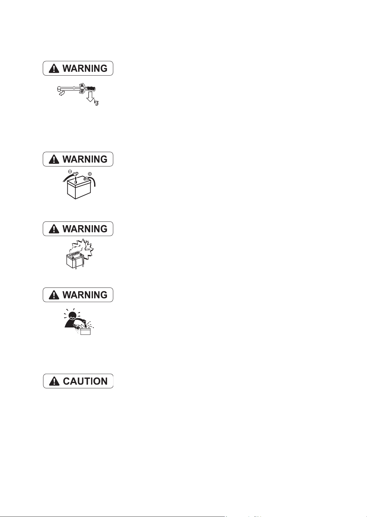
• Safety marks used in this manual and their meanings are as follows:
DANGER-indicates an imminent hazardous situation which, if
not avoided, WILL result in death or serious injury.
WARNING-indicates a potentially hazardous situation which, if
not avoided, COULD result in death or serious injury.
CAUTION-indicates a potentially hazardous situation which, if
not avoided, may result in minor or moderate injury.
• NOTICE - indicates that if not observed, the product performance or quality may not be
guaranteed.

2. Safety Precautions
(1) SERVICE AREA
• Sufficient Ventilation
Inhalation of exhaust fumes and dust particles may be hazardous to ones
health. Running engines welding, sanding, painting, and polishing tasks
should be only done in well ventilated areas.
• Safe / Adequate Work Area
The service area should be clean, spacious, level and free from holes in
the floor, to prevent "slip" or "trip and fall" type accidents.
• Clean, orderly arranged place
No dust, mud, oil or parts should be left on the floor surface.
[Failure to Observe]
An unexpected accident may be caused.
• Bright, Safely Illuminated Area
The work area should be well lit or illuminated in a safe manner. For work
in enclosed or dark areas, a "drop cord" should be utilized. The drop cord
must have a wire cage to prevent bulb breakage and possible ignition of
flammable substances.
• Safety Equipment
Fire extinguisher(s), first aid kit and eye wash / shower station should be
close at hand (or easily accessible) in case of an emergency.

(2) WORK - WEAR (GARMENTS)
• Safe Work Clothing
Appropriate safety wear (gloves, special shoes/boots, eye/ear protection,
head gear, harness', clothing, etc.) should be used/worn to match the
task at hand. Avoid wearing jewelry, unbuttoned cuffs, ties or loose fitting
Well fitting !!
clothes around moving machinery. A serious accident may occur if caught
in moving/rotating machinery.
(3) TOOLS
• Appropriate Lifting / Holding
When lifting an engine, use only a lifting device (crane, jack, etc.) with
sufficient lifting capacity. Do not overload the device. Use only a chain,
cable, or lifting strap as an attaching device. Do not use rope, serious
injury may result.
To hold or support an engine, secure the engine to a support stand, test
bed or test cart designed to carry the weight of the engine. Do not
overload this device, serious injury may result
Never run an engine without being properly secured to an engine support
stand, test bed or test cart, serious injury may result.
• Appropriate Tools
Always use tools that are designed for the task at hand. Incorrect usage
of tools may result in damage to the engine and or serious personal
injury.
(4) GENUINE PARTS and MATERIALS
• Genuine Parts
Always use genuine YANMAR parts or YANMAR recommended parts
and goods. Damage to the engine, shortened engine life and or personal
injury may result.
(5) FASTENER TORQUE
• Torqueing Fasteners
Always follow the torque values and procedures as designated in the
service manual. Incorrect values, procedures and or tools may cause
damage to the engine and or personal injury.
(6) Electrical
• Short Circuits
Always disconnect the (-) Negative battery cable before working on the
electrical system. An accidental "short circuit" may cause damage, fire
and or personal injury. Remember to connect the (-) Negative battery
cable (back onto the battery) LAST
• Charging Batteries
Charging wet celled batteries produces hydrogen gas. Hydrogen gas is
extremely explosive. Keep sparks, open flame and any other form of
ignition away. Explosion may occur causing severe personal injury.
• Battery Electrolyte
Batteries contain sulfuric acid. Do NOT allow it to come in contact with
clothing, skin and or eyes, severe burns will result.
(7) WASTE MANAGEMENT
Observe the following instructions with regard to hazardous waste
disposal. Negligence of these will have a serious impact on environmental
pollution concerns.
1) Waste fluids such as lube oil, fuel and coolant shall be carefully put
into separate sealed containers and disposed of properly.
2) Do NOT dispose of waste materials irresponsibly by dumping them
into the sewer, overland or into natural waterways.
3) Waste materials such as oil, fuel, coolant, solvents, filter elements and
batteries, must be disposed of properly according to local ordinances.
Consult the local authorities or reclamation facility.

(8) FURTHER PRECAUTIONS
• Fueling / Refueling
Keep sparks, open flames or any other form of ignition (match, cigarette,
etc.) away when fueling/refueling the unit. Fire and or an explosion may
result.
• Hot Surfaces.
Do NOT touch the engine (or any of its components) during running or
shortly after shutting it down. Scalding / serious burns may result. Allow
the engine to cool down before attempting to approach the unit.
• Rotating Parts
Be careful around moving/rotating parts. Loose clothing, jewelry, ties or
tools may become entangled causing damage to the engine and or
severe personal injury.
• Preventing burns from scalding
1) Never open the radiator filler cap shortly after shutting the engine
down.
Steam and hot water will spurt out and seriously burn you. Allow the
engine to cool down before attempt to open the filler cap.
2) Securely tighten the filler cap after checking the radiator.
Steam can spurt out during engine running, if tightening loose.
• Safety Label Check
Pay attention to the product safety label.
A safety label (caution plate) is affixed on the product for calling special
attention to safety.
If it is missing or illegible, always affix a new one.

3. Precautions for Service Work
(1) Precautions for Safety
Read the safety precautions given at the beginning of this manual carefully and always mind safety in
work.
(2) Preparation for Service Work
Preparation is necessary for accurate, efficient service work. Check the customer ledger file for the
history of the engine.
• Preceding service date
• Period/operation hours after preceding service
• Problems and actions in preceding service
• Replacement parts expected to be required for service
• Recording form/check sheet required for service
(3) Preparation before Disassembly
• Prepare general tools, special service tools, measuring instruments, oil, grease, non-reusable parts,
and parts expected to be required for replacement.
• When disassembling complicated portions, put match-marks and other marks at places not
adversely affecting the function for easy reassembly.
(4) Precautions in Disassembly
• Each time a parts is removed, check the part installed state, deformation, damage, roughening,
surface defect, etc.
• Arrange the removed parts orderly with clear distinction between those to be replaced and those to
be used again.
• Parts to be used again shall be washed and cleaned sufficiently.
• Select especially clean locations and use clean tools for disassembly of hydraulic units such as the
fuel injection pump.
(5) Precautions for Inspection and Measurement
Inspect and measure parts to be used again as required to determine whether they are reusable or not.
(6) Precautions for Reassembly
• Reassemble correct parts in correct order according to the specified standards (tightening torques,
and adjustment standards). Apply oil important bolts and nuts before tightening when specified.
• Always use genuine parts for replacement.
• Always use new oil seals, O-rings, packing and cotter pins.
• Apply sealant to packing depending on the place where they are used. Apply of grease to sliding
contact portions, and apply grease to oil seal lips.
(7) Precautions for Adjustment and Check
Use measuring instruments for adjustment to the specified service standards.

CONTENTS
1. GENERAL ....................................................................................................................... 1
1.1 Exterior Views ..........................................................................................................................1
1.2 Specifications ...........................................................................................................................2
1.3 Engine Outline ..........................................................................................................................4
1.4 Piping Diagrams ....................................................................................................................... 7
1.5 Exhaust Gas Emission Regulation ...........................................................................................9
1.5.1 Engine identification (3JH4E)............................................................................................................ 9
1.5.2 Exhaust Gas Regulations ............................................................................................................... 10
1.5.3 Guarantee Conditions for Emission Standard................................................................................. 10
2. Inspection and Adjustment ............................................................................................ 12
2.1 Periodic Maintenance Schedule .............................................................................................12
2.2 Periodic Inspection and Maintenance Procedure ...................................................................14
2.2.1 Check before starting...................................................................................................................... 14
2.2.2 inspection after initial 50 hours or one month operation ................................................................. 17
2.2.3 Inspection every 50 hours or monthly ............................................................................................. 22
2.2.4 Inspection every 250 hours or one year.......................................................................................... 26
2.2.5 Inspection every 1,000 hours or four years..................................................................................... 31
2.3 Adjusting the no-load maximum or minimum speed ..............................................................38
2.4 Sensor Inspection ..................................................................................................................38
2.4.1 Oil pressure switch ................................................................... 38
2.4.2 Thermo switch....................................................................... 38
2.5 Thermostat inspection ............................................................................................................ 39
2.6 Adjusting Operation ................................................................................................................40
2.6.1 Preliminary Precautions .................................................................................................................. 40
2.6.2 Adjusting operation procedure ........................................................................................................ 40
2.6.3 Check Points and Precautions During Running.............................................................................. 41
2.7 Long storage .......................................................................................................................... 42
3. Troubleshooting .............................................................................................................43
3.1 Preparation before troubleshooting ........................................................................................43
3.2 Quick Reference Chart for Troubleshooting ...........................................................................44
3.3 Troubleshooting (Concerning engine and fuel injection equipment) ......................................53
3.4 Troubleshooting by measuring Compression Pressure .........................................................56
4. Disassembly and Reassembly ......................................................................................58
4.1 Disassembly and Reassembly Precautions ...........................................................................58
4.2 Disassembly and Reassembly Tools .....................................................................................59
4.2.1 General Handtools .......................................................................................................................... 59

4.2.2 Special Handtools ........................................................................................................................... 62
4.2.3 Measuring Instruments ................................................................................................................... 65
4.2.4 Other material ................................................................................................................................. 66
4.2.5 Measuring Instruments ................................................................................................................... 69
4.3 Disassembly and Reassembly ...............................................................................................72
4.3.1 Disassembly.................................................................................................................................... 72
4.3.2 Reassembly .................................................................................................................................... 82
5. Inspection and Servicing of Basic Engine Parts ............................................................ 93
5.1 Cylinder Block ........................................................................................................................93
5.1.1 Inspection of parts........................................................................................................................... 93
5.1.2 Cleaning of oil holes .................................................................. 93
5.1.3 Color check procedure.................................................................................................................... 93
5.1.4 Replacement of cup plugs .............................................................................................................. 94
5.1.5 Cylinder bore measurement............................................................................................................ 95
5.2 Cylinder Head ........................................................................................................................96
5.2.1 Inspecting the cylinder head ........................................................................................................... 97
5.2.2 Valve seat correction procedure........................................................ 98
5.2.3 Intake/exhaust valves, valve guides .................................................... 99
5.2.4 Valve springs ................................................................................................................................ 101
5.2.5 Assembling the cylinder head......................................................... 102
5.2.6 Measuring top clearance ............................................................. 102
5.2.7 Intake and exhaust rocker arms....................................................... 103
5.2.8 Adjustment of valve clearance ...................................................................................................... 103
5.3 Piston and Piston Pins ..........................................................104
5.3.1 Piston ............................................................................................................................................ 104
5.3.2 Piston pin .......................................................................... 105
5.3.3 Piston rings ........................................................................ 105
5.4 Connecting Rod ................................................................108
5.4.1 Inspecting the connection rod......................................................... 108
5.4.2 Crank pin metal............................................................................................................................. 109
5.4.3 Piston pin bushing .................................................................. 111
5.4.4 Assembling piston and connecting rod ................................................. 111
5.5 Crankshaft and Main Bearing ...............................................................................................112
5.5.1 Crankshaft..................................................................................................................................... 112
5.5.2 Main bearing ....................................................................... 115
5.6 Camshaft and Tappets ......................................................................................................... 116
5.6.1 Camshaft .......................................................................... 116
5.6.2 Tappets ......................................................................................................................................... 118

5.7 Timing Gear .........................................................................................................................119
5.7.1 Inspecting the gears...................................................................................................................... 119
5.7.2 Gear timing marks .................................................................. 119
5.8 Flywheel and Housing .......................................................................................................... 120
5.8.1 Position of top dead center and fuel injection timing..................................................................... 120
5.8.2 Damper disc and cooling fan ........................................................................................................ 121
6. FUEL INJECTION EQUIPMENT .................................................................................122
6.1 Fuel Injection Pump/Governor .............................................................................................122
6.1.1 Fuel system diagram ................................................................ 122
6.1.2 Fuel injection pump service data .................................................................................................. 123
6.1.3 Fuel injection pump structure........................................................................................................ 125
6.1.4 Removing a fuel injection pump.................................................................................................... 127
6.1.5 Installing a fuel injection pump...................................................................................................... 127
6.1.6 Adjusting fuel injection timing........................................................................................................ 127
6.1.7 Troubleshooting of fuel injection pump ......................................................................................... 128
6.1.8 Major faults and troubleshooting................................................................................................... 128
6.1.9 Tools ............................................................................................................................................. 131
6.2 Fuel Feed Pump ................................................................133
6.2.1 Construction of fuel feed pump........................................................ 133
6.2.2 Fuel feed pump specifications ...................................................................................................... 133
6.2.3 Disassembly and reassembly of fuel feed pump .......................................................................... 134
6.2.4 Fuel feed pump inspection............................................................................................................ 134
6.3 Fuel Filter .....................................................................136
6.3.1 Fuel filter specifications................................................................................................................. 136
6.3.2 Fuel filter inspection ...................................................................................................................... 136
6.4 Fuel Tank ............................................................................................................................. 137
7. INTAKE AND EXHAUST SYSTEM .............................................................................138
7.1 Intake System ......................................................................................................................138
7.1.1 Breather system (A reductor to intake air system of blowby gas)........................... 138
7.1.2 Diaphragm assy inspection........................................................................................................... 139
7.2 Exhaust System ................................................................................................................... 140
7.2.1 Construction.................................................................................................................................. 140
7.2.2 3Mixing elbow inspection .............................................................................................................. 140
8. LUBRICATION SYSTEM .............................................................................................141
8.1 Lubrication System ............................................................................................................... 141
8.2 Lube Oil Pump .....................................................................................................................142
8.2.1 Lube oil pump construction ........................................................... 142
8.2.2 Specifications of lube oil pump ..................................................................................................... 142

8.2.3 Lube oil pump disassembly and reassembly ................................................................................ 142
8.2.4 Lube oil pump inspection .............................................................................................................. 143
8.2.5 Oil pressure control valve construction ......................................................................................... 143
8.3 Lube Oil Filter ....................................................................................................................... 144
8.3.1 Lube oil filter construction ............................................................ 144
8.3.2 Lube oil filter replacement............................................................................................................. 144
8.4 Lube oil Cooler .....................................................................................................................144
8.4.1 Lube oil cooler construction .......................................................................................................... 144
8.4.2 Inspecting the lube oil cooler ........................................................................................................ 144
8.5 Rotary Waste Oil Pump (Optional) .......................................................................................145
9. Cooling Water System ................................................................................................. 146
9.1 Cooling Water System .........................................................................................................146
9.2 Seawater Pump .................................................................................................................... 148
9.2.1 Specifications of seawater pump .................................................................................................. 148
9.2.2 Seawater pump disassembly ........................................................................................................ 149
9.2.3 Seawater pump Inspection ........................................................... 149
9.2.4 Seawater pump reassembly ......................................................................................................... 149
9.3 Fresh Water Pump ..............................................................................................................150
9.3.1 Fresh water pump construction..................................................................................................... 150
9.3.2 Specifications of fresh water pump ............................................................................................... 151
9.3.3 Fresh water pump disassembly .................................................................................................... 151
9.3.4 Fresh water pump inspection........................................................................................................ 151
9.4 Heat Exchanger ................................................................................................................... 153
9.4.1 Heat exchanger construction ......................................................... 153
9.4.2 Specifications of heat exchanger ...................................................... 153
9.4.3 Disassembly and reassembly of the heat exchanger ................................................................... 153
9.4.4 Heat exchanger inspection ........................................................................................................... 153
9.5 Pressure cap and coolant recovery tank ..............................................................................154
9.5.1 Pressure cap construction............................................................ 154
9.5.2 Pressure cap pressure control ...................................................................................................... 154
9.5.3 Pressure cap inspection................................................................................................................ 154
9.5.4 Replacing filler neck...................................................................................................................... 155
9.5.5 Function of the coolant recovery tank .................................................. 156
9.5.6 Specifications of coolant recovery tank......................................................................................... 156
9.5.7 Mounting the coolant recovery tank .............................................................................................. 156
9.5.8 Precautions on usage of the coolant recovery tank ...................................................................... 156
9.6 Thermostat ...........................................................................................................................157
9.6.1 Functioning of thermostat ............................................................................................................. 157
9.6.2 Thermostat construction ............................................................. 157

9.6.3 Characteristics of thermostat ........................................................................................................ 157
9.6.4 Thermostat inspection................................................................................................................... 157
9.6.5 Testing the thermostat .................................................................................................................. 157
9.7 Bilge Pump and Bilge Strainer (Optional) ............................................................................158
9.7.1 Introduction ................................................................................................................................... 158
9.7.2 Description .................................................................................................................................... 159
9.7.3 Cautions........................................................................................................................................ 159
9.7.4 Assembly Procedure..................................................................................................................... 160
9.7.5 Cautions for Assembling ............................................................................................................... 162
9.7.6 Troubleshooting ............................................................................................................................ 163
10. Reduction and Reversing Gear ................................................................................. 164
11. REMOTE CONTROL (OPTIONAL) ........................................................................... 165
11.1 Remote Control system ......................................................................................................165
11.1.1 Construction of remote control system ....................................................................................... 165
11.1.2 Remote control device components............................................................................................ 165
11.2 Remote Control Installation ................................................................................................167
11.3 Remote Control Inspection .................................................................................................169
11.4 Remote Control Adjustment ...............................................................................................170
12. Electrical System ....................................................................................................... 171
12.1 Electrical System ..............................................................171
12.1.1 Wiring diagram............................................................................................................................ 172
12.2 Battery ................................................................................................................................ 174
12.3 Starting Motor .....................................................................................................................175
12.3.1 Specifications.............................................................................................................................. 175
12.3.2 Characteristics .................................................................... 175
12.3.3 Structure ..................................................................................................................................... 176
12.3.4 Wiring diameter of a starting motor............................................................................................. 177
12.4 Alternator Standard, 12V/60A ............................................................................................178
12.4.1 Specifications.............................................................................................................................. 178
12.4.2 Structure ..................................................................................................................................... 179
12.4.3 Wiring diagram .................................................................... 180
12.4.4 Standard output characteristics .................................................................................................. 180
12.4.5 Inspection.................................................................................................................................... 181
12.5 Alternator 12V/80A (Optional) ............................................................................................182
12.5.1 Specifications.............................................................................................................................. 182
12.5.2 Structure ..................................................................................................................................... 183
12.5.3 Wiring diagram .................................................................... 184
12.5.4 Standard output characteristics .................................................................................................. 184

12.6 Instrument Panel ................................................................................................................185
12.6.1 B-type instrument panel (optional).................................................... 185
12.6.2 C-type instrument panel ............................................................ 185
12.7 Warning Devices ................................................................................................................186
12.7.1 Oil pressure alarm....................................................................................................................... 186
12.7.2 Sender unit for lube oil pressure gauge ............................................... 187
12.7.3 Cooling water temperature alarm................................................................................................ 188
12.7.4 Sender unit for the cooling water temperature gauge ................................... 188
12.8 Air Heater (Optional) ..........................................................................................................189
12.9 Electric Engine Stopping Device (Optional) .......................................190
13. SERVICE STANDARDS ............................................................................................ 191
13.1 Engine Tuning ....................................................................................................................191
13.2 Engine Body ....................................................................................................................... 192
13.2.1 Cylinder head.............................................................................................................................. 192
13.2.2 Camshaft and gear train ............................................................................................................. 193
13.2.3 Cylinder block ............................................................................................................................. 194
13.3 Lubricating Oil System (Trochoid Pump) ...........................................................................196
14. TIGHTENING TORQUE FOR BOLTS AND NUTS ................................................... 197
14.1 Main Bolt and Nut ............................................................................................................... 197
14.2 Standard Bolts and Nuts (without lube oil) .........................................................................197

1. GENERAL
1.1 Exterior Views
(1) 3JH4E
Operating Side
1. GENERAL
Intake silencer Intake manifold Dipstick
Fuel filter
Fuel injection pump
Oil filter cap
Shift lever
Marine gear Oil cooler
Non-Operating Side
Fuel feed pump
Lubricating oil filter
Engine name plate (on the rocker arm cover)
Fresh water filler cap
Coolant tank / Heat exchanger
Alternator
Exhaust manifold
Mixing elbow
Starter motor
Sea water pump
<Note> This illustration shows the 3JH4E with Yanmar marine gear (Model:KM35P).
1

1. GENERAL
1.2 Specifications
(1) 3JH3E, 3JH3BE, 3JH3CE, 3JH4ME
Official engine model name unit 3JH4E
Company internal model name
Marine gear model - KM35P KM35A SD40 Bobtail
Use - Pleasure use
Type - Vertical water cooled 4 cycle diesel engine
Combustion system - Direct injection
Air charging - Naturally aspirated
Number of cylinders - 3
Bore x stroke mm(inch) 88 x 90 (3.46 x 3.54)
Displacement L 1 .642
Continuous
power
Fuel stop
power
Installation - Flexible mounting
Fuel injection timing
Fuel injection opening
pressure
Main power take off - At flywheel side
Direction of
rotation
Cooling system - Fresh water cooling with heat exchanger
Lubrication system - Complete enclosed forced lubrication
Cooling water capacity (fresh)
Lubricating
oil capacity
(engine)
Starting
system
Engine
Dimension
Flywheel major dimension mm(inch) Ø300 x 66 (11.8 x 2.6)
Engine dry mass
(include marine gear)
Output at
crankshaft /
Engine speed
Output at
crankshaft /
Engine speed
Output at
propeller shaft /
Engine speed
Crankshaft - Counter-clockwise viewed from stern
Propeller shaft
(Ahead)
Rake angle deg.
Total (Note 4)
Oil pan only
Effective (Note 5)
Type - Electric
Starting motor
AC generator V-A 12V-60A (12V-80A optional)
Overall length
Overall width 539 (21.2) 539 (21.2) 539 (21.2) 539 (21.2)
Overall height 623 (24.5) 623 (24.5) 623 (24.5) 623 (24.5)
- 3JH4E 3JH4BE 3JH4CE 3JH4ME
kW(HP)/
-1
min
kW(HP)/
-1
min
kW(HP)/
min
deg b.T.D.C.
MPa
(kgf/cm
L(quart) Engine:4.5 (4.8), Coolant recovery tank : 0.8 (0.8)
L(quart)
V-kW
mm(inch)
kg 185 186
28.0(38.1) / 3000 (at Fuel temp. 25°C)*
-1
27.4(37.3) / 3000 (at Fuel temp. 40°C) **
2
)
- Clockwise viewed from stern - -
at rake angle 8 deg
5.0±0.3 (5.3±0.3) 5.5±0.3 (5.8±0.3) 5.5±0.3 (5.8±0.3) 5.5±0.3 (5.8±0.3)
4.5±0.3 (4.8±0.3) 5.0±0.3 (5.3±0.3) 5.0±0.3 (5.3±0.3) 5.0±0.3 (5.3±0.3)
1.1 (1.2) 1.2 (1.3) 1.2 (1.3) 1.2 (1.3)
777 (30.6) 776 (30.6) 700 (27.6) 700 (27.6)
26.7(36.3) / 2907 (at Fuel temp. 25°C)*
29.4(40.0) / 3000 (at Fuel temp. 25°C)*
28.7(39.0) / 3000 (at Fuel temp. 40°C)* *
--
FID 12±1 (FIC-Air 13±1)
21.6±0.5 (2.12±0.05)
at rake angle 0 deg -
DC 12V-1.4 kW
212
(engine:173)
173
2

1. GENERAL
(Note)
1. Rating condition : ISO 3046-1, 8665
2. 1HP (metric horse power) ≒ 0.7355 kW
3. Fuel condition : Density at 15°C = 0.842
* Fuel temperature 25°C at the inlet of the fuel injection pump. (ISO 3046-1)
** Fuel temperature 40°C at the inlet of the fuel injection pump. (ISO 8665)
4. The "Total" oil quantity includes: oil in oil pan and oil in channels, coolers and filter.
5. The effective amount of oil shows the difference in maximum scale of the dipstick and minimum scale.
(2) Sales condition, Marine gear
Reduction ratio
(Marine gear
model)
2.61 (KM35P)
2.64 (KM35A)
2.36 (KM35P)
2.33 (KM35A)
Outer diameter
No. of blades
3 (A/R=0.52) 18
4 (A/R=0.69) 17
3 (A/R=0.52) 18
4 (A/R=0.69) 17
of propeller
(inch)
Moment of
propeller inertiaI
2
GD
N•m2 (kgf•m2)
2.94 (0.30)
2.55 (0.26)
propeller
materials
Bronze 3JH4(B)E
Engine
application
3

1.3 Engine Outline
(1) 3JH4E (with KM35P marine gear)
1. GENERAL
MIXING ELBOW
U-MIXING ELBOW
174
MOUNTING BLOCKS ID#150
DIRECTION OF ROTATION
+0.025
100
50
0
6 7.5
32
4
210
210
(OPTIONAL)
60
169.3
12 X 30
MOUNTING BLOCKS ID#100
174
206
412 190
143
7
120
0
+0.025
50
DETAIL OF PULLEY
SCALE 1:3
3-M10 X 1.5
DEPTH 14 / 20
4- 10.5
PC 78
DETAIL OF COUPLING
SCALE 1:3
538.6
4
(274)
517.6
243.6
194.1
65 32
MIN. 100
MAX. 110
167
ROTATION
120.493.2
330
480
191.2 431.4
622.6
(202.5)(65)
(72.5)
6 724.3 47
777.3
NOTE
1. The original height of mounting blocks is shown
in this drawing. Engine weight will compress
blocks by 4mm (approx).
2. The figures marked with show the dimensions
with u-mixing elbow, or optional coupling.

(2) 3JH4BE(with KM35A Marine gear)
MIXING ELBOW
U-MIXING ELBOW
MOUNTING BLOCKS ID#150
DIRECTION OF ROTATION
6 7.5
3-M10 X 1.5
DEPTH 14 / 20
0
+0.025
DETAIL OF COUPLING
210
210
7
0
60
+0.025
DETAIL OF PULLEY
SCALE 1:3
SCALE 1:3
12 X 30
538.6
194.1
517.6
243.6
(OPTIONA
L)
5
(274)
174
206
168
MOUNTING BLOCKS ID#100
143
412 190
MIN. 100
MAX. 110
79.5
ASTERN
AHEAD
5.955
(202.5)
(72.5)
723 47
776
NOTE
1. The original height of mounting blocks is shown
in this drawing. Engine weight will compress
blocks by 4mm (approx).
2. The figures marked with show the dimensions
with u-mixing elbow, or optional coupling.
1. GENERAL
ROTATION
32
167
120.493.2
330
480
622.6
191.2 431.4

1. GENERAL
(274)
194.1
538.6
517.6
243.6
MOUNTING BLOCKS ID#200
MOUNTING BLOCKS ID#200
185 538
(OPTIONA
L)
(3) 3JH4CE (with SD40 sail drive)
7
210
DIRECTION OF ROTATION
3-M10 X 1.5
DEPTH 14 / 20
0
210
+0.025
60
174
206
12 X 30
143
DETAIL OF PULLEY
SCALE 1:3
6
431.4
MAX. 110
MIN. 105
(266.4)
(202.5)
605
(185)
(202.5)
(112.5)
538
973
372
143
47
210
641.4
1036.4
395
32
167
420
480
NOTE
1. The original height of mounting blocks is shown
in this drawing. Engine weight will compress
blocks by 4mm (approx).
2. The figures marked with show the dimensions
Available propeller dia. 181 inch max.
with u-mixing elbow, or optional coupling.

1.4 Piping Diagrams
(1) 3JH4(B) E
Note: The following piping diagram is for the 3JH4E model.
Marks of piping
Screw joint (Union)
Flange joint
Eye joint
Insertion joint
Drill hole
Cooling fresh water piping
Cooling seawater piping
Lubricating oil piping
Fuel oil piping
Fuel oil filter (cartridge type)
Pressure control valve
Lubricating oil pump
Fresh water temperature switch
7.8 x t4.5 rubber hose
7.8 x t4.5 rubber hose
Check valve
7.8 x t4.5 rubber hose
D
Overflow
Fuel oil inlet
7.8 x t4.5 rubber hose
5 x t4.5
rubber hose
C
P
7.8 x t4.5 rubber hose
Fuel feed pump
Fuel injection pump
4.76 x t0.7 steel pipe
9 x t3.5 rubber hose
Lubricating oil filter (cartridge type)
Lubricating oil cooler
5 x t4.5 rubber hose
Fuel high pressure pipe
1.General
30
26
Detail of part A
45
76.3
27 x t4 rubber hose
Hot water connection inlet (R3/8)
Cooling water pump (fresh water)
28.6 x t2 copper pipe
Thermostat
Hot water connection outlet (R3/8)
28 x t4 rubber hose
28 x t4 rubber hose
Cooling water pump (seawater)
P
Fuel injection nozzle
9 x t3.5 rubber hose
Oil pressure switch
To oil pan
P
P
T
From
cylinder
head
To cam shaft
Detail of part B
9
8
17
B
Detail of part C
Mixing elbow
8.5
8
25.4 x t4.3 rubber hose
Notes
1. Dimension of steel pipe : outer dia. x thickness.
Dimension of rubber pipe : inner dia. x thickness.
2. Fuel rubber pipes (marked ) satisfy EN/ISO7840.
A
Seawater inlet
Lubricating oil inlet filter
Main bearing
25 x t1.8 copper pipe
7
Fresh water cooler
16.5
25.4 x t4.3 rubber hose
25.4 x t4.3 rubber hose
Detail of part D

(2) 3JH4CE (with sail drive SD40)
Marks of piping
Screw joint (Union)
Flange joint
Eye joint
Insertion joint
Drill hole
Cooling fresh water piping
Cooling seawater piping
Lubricating oil piping
Fuel oil piping
7.8 x t4.5 rubber hose
Fuel oil filter (cartridge type)
Pressure control valve
Lubricating oil pump
Fresh water temperature switch
7.8 x t4.5 rubber hose
7.8 x t4.5 rubber hose
Check valve
D
Overflow
Fuel oil inlet
7.8 x t4.5 rubber hose
5 x t4.5
rubber hose
C
P
7.8 x t4.5 rubber hose
Fuel feed pump
Fuel injection pump
4.76 x t0.7 steel pipe
9 x t3.5 rubber hose
Lubricating oil filter (cartridge type)
Lubricating oil cooler
5 x t4.5 rubber hose
Fuel high pressure pipe
1.General
45
76.3
27 x t4 rubber hose
Hot water connection inlet (R3/8)
Cooling water pump (fresh water)
28.6 x t2 copper pipe
Thermostat
Hot water connection outlet (R3/8)
28 x t4 rubber hose
28 x t4 rubber hose
Cooling water pump (seawater)
P
Fuel injection nozzle
9 x t3.5 rubber hose
Oil pressure switch
To oil pan
P
P
T
From
cylinder
head
To cam shaft
B
Mixing elbow
Detail of part B
9
8
17
Detail of part C
8.5
8
16.5
Notes
1. Dimension of steel pipe : outer dia. x thickness.
Dimension of rubber pipe : inner dia. x thickness.
2. Fuel rubber pipes (marked ) satisfy EN/ISO7840.
25.4 x t4.3 rubber hose
Main bearing
25 x t1.8 copper pipe
8
Fresh water cooler
Lubricating oil inlet filter
25.4 x t4.3 rubber hose
25.4 x t4.3 rubber hose
25.4 x t4.3 rubber hose
Detail of part D

1.general
1.5 Exhaust Gas Emission Regulation
The EPA and ARB (,California Air Resources Board)
Off-road Compression Ignition engines regulations
1.5.1 Engine identification (3JH4E)
With the regulations on exhaust gas emission worldwide, it has become necessary to identify engines in
a manner to determine which regulations they comply with, hence
(1) Emission control label
(EPA and ARB label)
(Note) Emission Control is accomplished through Engine Modification (EM-Design)
• The tamper resistance device is installed with EPA/ARB certified 3JH4E series engines to prevent
illegal change of fuel injection volume and high idling speed.
(Fuel injection volume : cap type, High idling speed : cap type)
• Engine family name as assigned by EPN/ARB identifying engine family group
4YDXM1.64D3N and this identifies
YYDXM1.64D3N and this identifies
4 YDX M 1.64 D 3 N
Method of air aspiration
Number of cylinders
Combustion chamber design
Displacement (liter)
Marine engine
Y : 2000
1 : 2001
2 : 2002
3 : 2003
4*: 2004
5 : 2005
Yanmar
*2004 Model Year
(2) Label location:
Emission control label
9

1.General
1.5.2 Exhaust Gas Regulations
This engine conforms to the EPA exhaust gas regulations (19kW and under 37kW).
Engine Power Tier Model Year NOx HC
19 <= kW < 37
(25 <= hp < 50)
Tier 1 1999 - - 9.5 (7.1) 5.5 (4.1) 0.80 (0.60)
Tier 2 2004 - - 7.5 (5.6) 5.5 (4.1) 0.60 (0.45)
NMHC + NOx
CO PM
Note
1. The transit smoke (ACC/LUG/PEAK) is not applicable.
2. The EPA recommended fuel is used.
3. The ARB standard is the same as the EPA's.
1.5.3 Guarantee Conditions for Emission Standard
In addition to making sure that these conditions are met, check for any deterioration that may occur
before the required periodic maintenance times.
(1) Requirement on engine installation condition
(a) Air intake negative pressure
kPa (mmAq)
Permissible
¹3.9 (400)
(b) Exhaust gas back pressure
kPa (mmAq)
Permissible
¹14.7 (1500)
(2) Fuel oil and lubricating oil
(a) Fuel: The diesel fuel oil [BS 2869 A1 or A2 (Cetane No.45 min.)]
(b) Lube oil : API grade, class CD
(3) Do not remove the caps restricting injection quantity and engine speed.
(4) Perform maintenance without fail.
Note : Inspections to be carried out by the user and by the maker are divided and set down in the "List of
Periodic Inspection" on the operation manual and should be checked carefully.
EPA allows to apply Maintenance schedule for Emission related parts as follows.
Maintenance period
Parts
Power Rating
19 ¹ kW < 37 Every 1500 hours Every 3000 hours
Fuel nozzle cleaning Adjustment, cleaning, repairs for fuel
nozzle, fuel pump, and electronic control
unit etc.
10

1.general
(5) Quality guarantee period for exhaust emission related parts
For exhaust emission related parts, follow the inspections outlined in the "List of Periodic Inspections",
on the operation manual, and use the table below to carry out inspections based on operation hours or
time in years. Whichever comes first is the guarantee period.
19 ¹ kW < 37 3000 hours or 5 years
The specific emissions-related parts are
(a) Fuel injection nozzle
(b) Fuel injection pump
11

2. Inspection and Adjustment
2. Inspection and Adjustment
2.1 Periodic Maintenance Schedule
The engine periodic inspection timing is hard to determine as it varies with the application, load status,
qualities of the fuel and lubricating oils used and handling status. General rules are described here.
{ : User-maintenance Å : Parts replacement z : Shop-inspection
System Item
Whole Visual inspection of engine outside {
Check the fuel level, and refill {
Drain the fuel tank { {
Drain the fuel/water separator {
Fuel system
Lubricating
system
Replace the fuel filter
Check the injection timing z
Check the injection spray condition
Check the lube oil
level
Replace the lube
oil
Crankcase {
Marine gear {
Crankcase
Marine gear
Before
starting
2
Initial
*
50hrs. or
one month
Å Å
ÅÅ
2
Every
*
50hrs. or
one month
2
*
Every
250 hrs. or
one year
Å
2
*
Every
1000 hrs. or
4 years
1
z*
Cooling
system
Air intake
and
exhaust
system
Electrical
system
Replace the engine lube oil filter.
{
Seawater outlet
Check cooling water level
Check the impeller of the cooling
water pump (seawater pump)
Replace the fresh water
Clean & check the water passages z
Clean the element of the air intake
silencer
Clean the exhaust/water mixing
elbow
Diaphragm assembly inspection z
Check the alarm lamps & devices {
Check the electrolyte level in the
battery
Adjust the tension of the alternator
driving belt
Check the wiring connectors {
(During
operation)
{
When long life coolant of the specified type is used, the
replacement period of two years can be obtained.
ÅÅ
{
Every year
-
{
{
{{
Å
Å
12

2. Inspection and Adjustment
{ : User-maintenance
System Item
Check the leakage of water,
Cylinder
head,
etc.
lube oil and fuel.
Retighten all major nuts and bolts z
Adjust intake/exhaust valve
clearance
Remote
control
system, etc.
*1
For EPA requirements see also 1.5 in chapter 1.
*2
Whichever comes first
Check/adjust the remote control
operation
Adjust the propeller shaft alignment zz
Å : Parts replacement z : Shop-inspection
Before
starting
*2 Initial
50hrs. or
one month
{
(After
starting)
z z
{{ z
*2 Every
50hrs. or
one month
*2 Every
250 hrs. or
one year
*2 Every
1000 hrs. or
4 years
13

2. Inspection and Adjustment
2.2 Periodic Inspection and Maintenance Procedure
2.2.1 Check before starting
Be sure to check the following points before starting an engine every day.
No. Inspection Item
(1) Visual inspection of engine outside
(2) Check the fuel level, and refill
(3) Check the lube oil level (Crankcase/Marine gear)
(4) Seawater outlet
(5) Check cooling water level
(6) Check the alarm lamps & devices
(7) Check the leakage of water, lube oil and fuel.
(8) Check/adjust the remote control operation
(1) Visual inspection of engine outside
If any problem is found, do not use before the engine repairs have been completed.
• Oil leak from the lubrication system
• Fuel leak from the fuel system
• Cooling water leak from the cooling water system
• Damaged parts
• Loosened or lost bolts
• Fuel, coolant tank rubber hoses, V belt cracked, loosened clamp
(2) Check the fuel level, and refill
Check the remaining fuel oil level in the fuel tank and refuel the recommended fuel if necessary.
(3) Check the lube oil level (Crankcase/Marine
gear)
1) Checking engine lube oil level
a) Check the lube oil level of a engine with a
dipstick. Insert the dipstick fully and check the oil
level. The oil shall not be contaminated heavily
and have appropriate viscosity. No cooling water
or diesel fuel shall be mixed.
Standard
The level shall be between the upper and lower limit
lines on the dipstick.
Unit: liter(quart)
Model
3JH4E with KM35P Full : 5.0 ± 0.3 (5.3 ± 0.3)
3JH4E with KM35A
3JH4E with SD40
Engine oil capacity
at rake angle 8 degree
Full : 5.5 ± 0.3 (5.8 ± 0.3)
b) If the remaining engine oil level is low, fill the oil pan with the specified engine oil to the specified
level through the filler port.
Rocker arm cover
Filter port
Dipstick
Upper limit
Lower limit
[NOTICE]
The engine oil should not be overfilled to exceed the upper limit line. If engine oil is overfilled, the
engine may intake the engine oil in the combustion chamber during the operation, and white smoke, oil
hummer or urgent rotation may occur, because the blowby gas is reduced in the suction air flow.
14
 Loading...