

Page 1

INSTRUCTION MANUAL
FOR
Vacuum Controller
The 2nd Edition
The 2nd Edition
The 2nd EditionThe 2nd Edition
VR100
Yamato Scientific
Yamato Scientific Co
Yamato Scientific Yamato Scientific
2-1-6,
2-1-6, Nihonbashi Honcho, Chuo-
2-1-6, 2-1-6,
Congratulations on your selection of Yamato Scie ntific’s VR100!
Please read these operating instructions, user notes and the warranty card thoroughly before the
initial operatio n of your VR100. This will ensure proper operati ng procedures and extended life for the
unit. Please keep the operating instructions together with the warranty card for easy access
whenever you need them.
Nihonbashi Honcho, Chuo-ku
Nihonbashi Honcho, Chuo-Nihonbashi Honcho, ChuoTokyo 103-8432 JAPAN
Tokyo 103-8432 JAPAN
Tokyo 103-8432 JAPANTokyo 103-8432 JAPAN
Co...., Ltd.
, Ltd.
CoCo
, Ltd., Ltd.
ku
kuku
Page 2

TABLE OF CONTENTS
Explanation of Picture Display......................................................................................1
Cautions in Using with Safety.......................................................................................2
Notes to Users................................................................................................................3
Description and Function of Each Part.....................................................................................3
Requiremen ts for Installa tion....................................................................................................5
Handling Precautions ....................................................................................................9
Corrosive Resistance.............................................................................................................11
Operation ......................................................................................................................12
The Fixed Value Control.........................................................................................................13
Changing the Set point While the Fixed Value Control Operates............................................14
The Ramp Control..................................................................................................................15
The Free Mode ......................................................................................................................16
Shutdown...............................................................................................................................17
Restart...................................................................................................................................17
Shifting to Oth er Operation .....................................................................................................18
Using the Function Menu.............................................................................................19
Calibrating Measurements.....................................................................................................20
Editing the Set point of the Ramp control...............................................................................21
Error ..............................................................................................................................24
Maintenance..................................................................................................................25
Daily Inspection and Maintenance..........................................................................................25
Replacing Fuse......................................................................................................................26
After Service and Warranty..........................................................................................27
If a Service Call is required:...................................................................................................27
Troubleshooting .....................................................................................................................27
Specifications...............................................................................................................28
Wiring Diagram.............................................................................................................29
Replacement Parts Table.............................................................................................30
Reference......................................................................................................................31
Dangerous Substances..........................................................................................................31
Pressure Conversion..............................................................................................................32
Explanation of Character on the display.................................................................................32
Page 3

Explanation of Picture Display
MEANING OF ILLUSTRATED SYMBOLS
Illustrated Symbols
Various symbols are used in this safety manual in order to use the unit without
danger of injury and damage of the unit. A list of problems caused by ignoring the
warnings and improper handling is divided as shown below.Be sure that you
understand the warnings and cautions in this manual before operating the unit.
Warning
Caution
If the warning is ignored, there is the danger of a problem that may
cause a serious accident or even fatality.
If the caution is ignored, there is the danger of a problem that may
cause injury/damage to property or the unit itself.
Meaning of Symbols
This symbol indicates items that urge the warning (including the caution).
A detailed warning message is shown adjacent to the symbol.
This symbol indicates items that are strictly prohibited.
A detailed message is shown adjacent to the symbol with specific actions not to
perform.
This symbol indicates items that should be always performed.
A detailed message with instructions is shown adjacent to the symbol.
1
Page 4

Cautions in Using with Safety
WARNING
Do not use the unit in an area where there is flammable or explosive gas.
••••
Never use the unit in an area where there is flammable or explosive gas.
The unit is not explosion-proof. An arc may be generated when the power switch is turned on or off, and
fire/explosion may result.
Always ground the unit.
••••
Always ground the unit on the power equipment side in order to avoid electrical shock due to a power surge.
If a problem occurs, you should:
••••
If smoke or strange odor should come out of the unit for some reason,
off
the circuit breaker and the main power. Immediately contact a service technician for inspection. If this
procedure is not followed, fire or electrical shock may resul t.
Never perform repair work yourself, since it is dangerous and not recommended.
Do not use the power cord if it is bundled or tangled.
••••
Do not use the power cord if it is bundled or tangled. If it is used in this manner, it can overheat and fire may be
caused.
turn off
the power key right away, then
turn
Do not process, bend, wring, or stretch the power cord forcibly.
••••
Do not process, bend, wring, or stretch the power cord forcibly. Fire or electrical shock may result.
Substances that can not be used.
••••
Never use explosive substances, flammable substances and substances that include explosive or flammable
ingredients in the unit. Explosion or fire may occur.
Do not disassemble or modify the unit.
••••
Do not reconfigure the unit. Fire or electrical shock may be caused.
CAUTION
During a thunder storm
••••
During a thunder storm,
If this procedure is not followed, fire or electrical shock may be caused.
turn off
the power key immediately, then
turn off
the circuit breaker and the main power.
2
Page 5
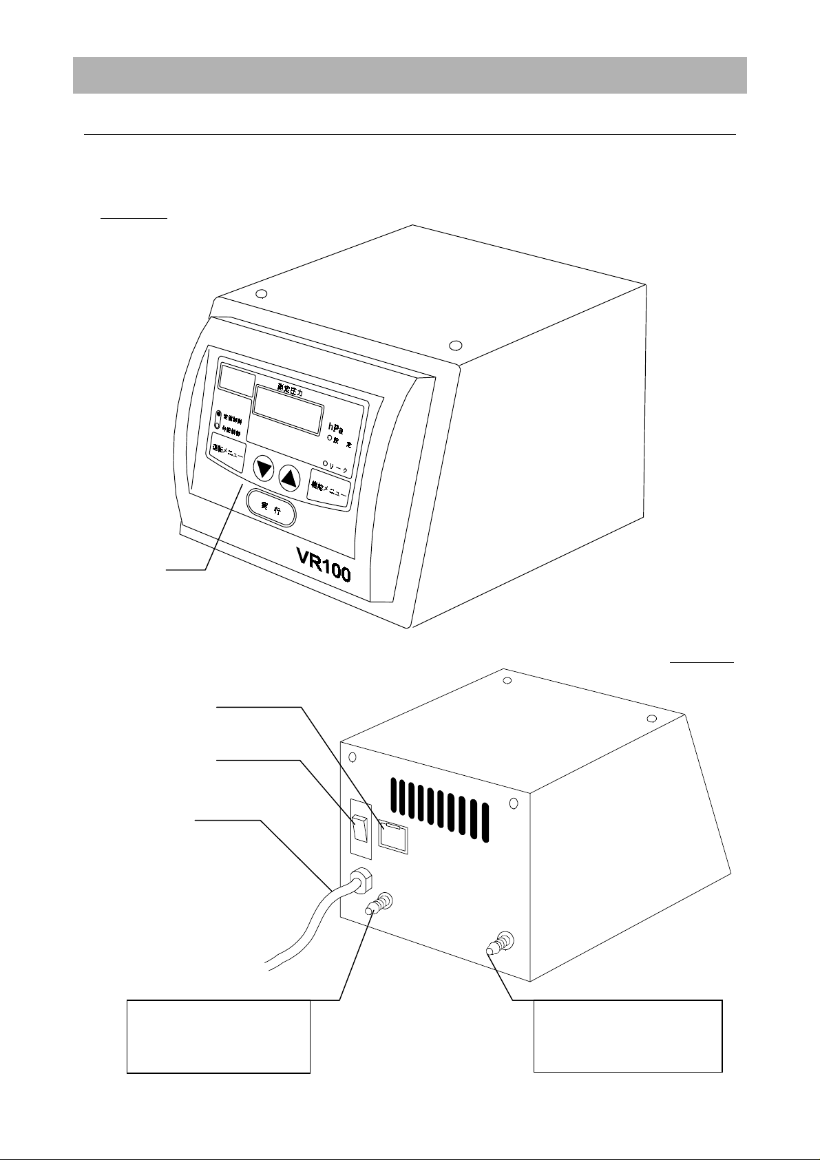
Main unit
Front view
Notes to Users
Description and Function of Each Part
Control panel
Power Switch
Power Cord
Rear view
Fuse Box
Connection for Evaporator
Port for Hose:
Outside Diameter 10mm,
Nominal Size 1/8 x 5/16
Connection for Aspirator
Port for Hose
Outside Diameter 10mm,
Nominal Size 1/8 x 5/16
3
Page 6
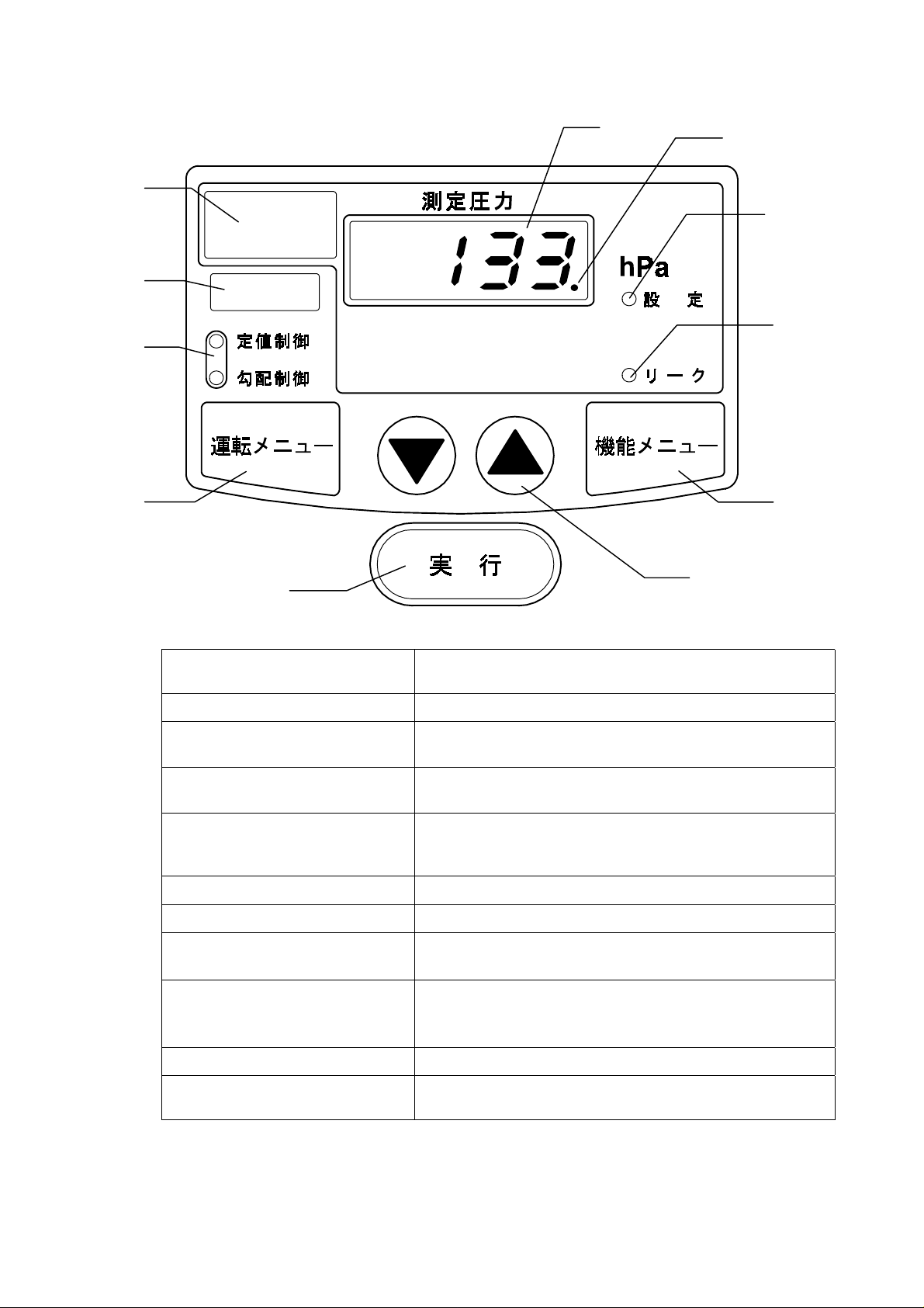
Control Panel
①
⑩
Main Display:
①
Solenoid Valve Lamp (LED):
②
Blind Window:
③
Edit Mode Display Lamp
④
(LED)
Operation Mode Display
⑤
Lamp
Set Mode Display Lamp
⑥
Leak Lamp
⑦
Operation Menu Key
⑧
Function Menu Key
⑨
Up/Down Key
⑩
Enter Key
⑪
Displays measureme nts, set points ( indicated as ~h Pa),
literal informations in the ramp control editing, etc.
Lit while the solenoid valve for control opens.
Indicates a blinking
abnormality occurred.
Lights up
selected.
indicates a selected operation mode. It is lit while
operation, and blinked in the set mode and the edit
mode. Nothing is indicated in the free mode.
lit when settings and edits are done.
lit while the leak valve opens.
used to select one of the following operations.「the fixed
value control」,「the ramp control」,「the free mode
used to select the function;「the measurement
calibrating mode」in the fixed value control and 「the
edit mode」 in the ramp control.
used to change the set point.
used to decide or input set points and modes, such as
operation, calibration, edit.
「編集」
「異常」
(Means
(Means
EDIT
TROUBLE
) when the edit mode is
) when an
」
4
Page 7

Requirements for Installation
Installation to Rotary Evaporator RE400/500/440/540
1. 2.
Unscrew the
screw which fix
the rubber-leg of
the body.
Rubber leg Metal Fixture
3. 4.
Fix the metal
fixture to the
rear of the
control unit with
four screws.
Control Unit of
RE400/500
Fix the metal
fixture
provided as
standard
accessories
with flat-head
screws.
Put the
power plug of
the vacuum
regulator in
the outlet at
the rear of
the control
unit.
5.
Finished View
Power Cord Plug
VR100
RE400/500/440/540
Being the auto lift style, the body-outlook of
RE440/540 is not the same as the drawing on the
left.
5
Page 8
Warn ing
Warning
WarningWarning
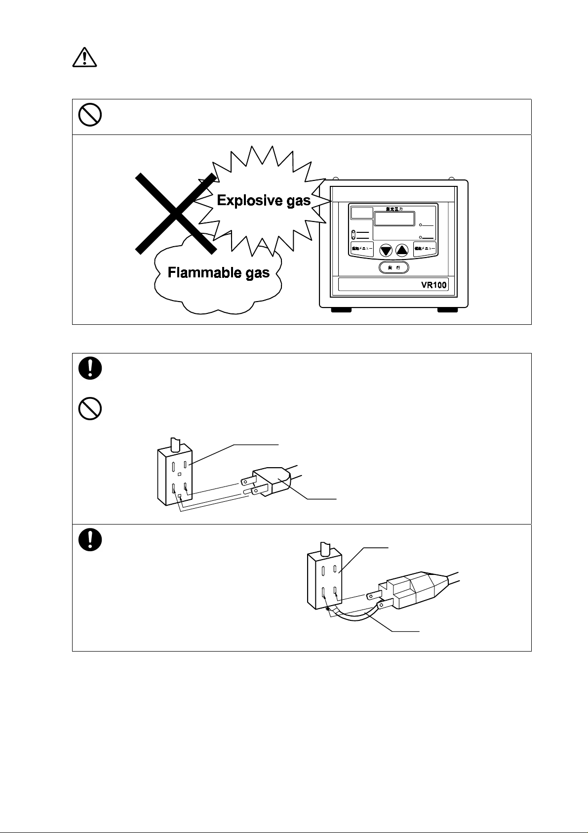
Do not use the unit in an area where there is flammable or explosive gas.
•
Never use the unit in an area where there is flammable or explosive gas. The unit is not explosion-
proof. An arc may be generated when the power switch is turned ON or OFF, and fire/explosion may
result.
Always ground the unit.
•
Connect VR100’s power plug to a receptacle with grounding connectors.
•
Do not forget to ground VR100, to protect you and the uni t from electr ical sho ck in cas e of pow er surge.
Choose a receptacle with grounding connectors as often as possible.
•
Do not connect the grounding wire to a gas pipe, or by means of a light ni ng ro d or t ele pho ne line. A fire
or electrical shock will occur.
•
If only bipolar receptacles are available for
VR100, connect an optional grounding
adapter to VR100’s power plug. Check
the polarity of the receptacle before
connecting the adapter to the receptacle.
Connect the adapter’s grounding wire
(green) to a grounding terminal to the
power supply. Contact our sales
representative in your vicinity or our service
center for additional information or
assistance.
100V receptacle with grounding terminals
Power plug
100V bipolar receptacle
Grounding wire
6
Page 9

Choose a correct power distribution board or receptacle.
•
Choose a correct power distribution board or receptacle that meets VR100’s rated electric capacity.
Electric capacity : AC100 V, 1A
•
Do not connect VR100 to an outlet that differs from the above spe cif ic ations because a fire or electrical
shock will occur.
Install on a level area.
•
Do not installation VR100
on a non level surface.
This will cause hazards to
the operator and create
problems during actual
operation.
Choose a proper place for installation.
•
Do not install VR100 in a place where:
Flammable gas or corrosive gas is generated.
♦
Ambient temperature exceeds 35°C, also bellow 5°C.
♦
Ambient temperature fluctuates violently.
♦
There is direct sunlight.
♦
There is excessive humidity and dust.
♦
There is constant vibrations.
♦
•
Keep the clearance over 15cm around VR100.
7
Page 10
Caution
Caution
CautionCaution
Handling of power code.
•
Do not entangle the power cord. This will cause overheating and possibly a fire.
•
Do not bend or twist the power cord, or apply excessive tension to it. This may cause a fire and
electrical shock.
•
Do not lay the power cord under a desk or chair, and do not allow it to be pinched in order to prevent it
from being damaged and to avoid a fire or electrical shock.
•
Keep the power cord away from any heating equipment such as a room heater. The cord's insulation
may melt and cause a fire or electrical shock.
•
If the power cord becomes damaged (wiring exposed, breakage, etc.), immediately turn off the power
at the rear of the product and shut off the main supply power. Then contact your nearest dealer for
replacement of the power cord. Leaving it may cause a fire or electrical shock.
•
Connect the power plug to the outlet which is suppl ied appr opriate pow er and voltage . If the p ow er cord
is connected the supply which is also connected to a aspirator or a vacuum pomp etc., with no
sufficient power and voltage, the product may not operate properly because the power would fall.
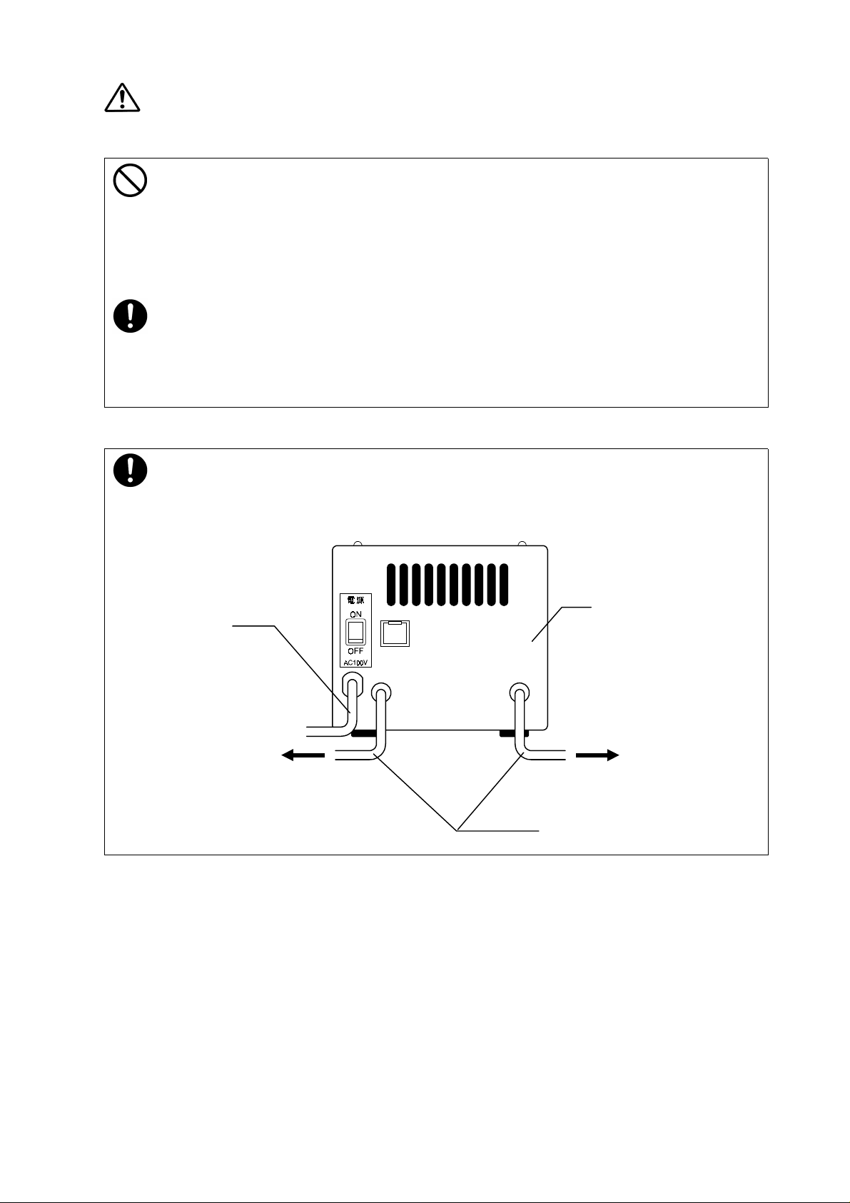
Piping
•
Vacuum hoses (outside diameter 12 x inside diameter 6mm) are required. These are not included in
accessories.
•
Refer to figure below in order to pipe. Stickers that indicate where to connect are attached at the rear.
Connect the pipes correctly in accordance with each indication of them.
Power code
to condenser's
decompression
port of ROTARY
EVAPORATOR
The rear of the body
to suction port of
ASPIRATOR
Vacuum Hose
8
Page 11

Warn ing
Warning
WarningWarning
Approaching Thunderstorm
•
If a thunderstorm approaches in the distance, immediately turn off the power at the rear panel and shut
off the supply power. Leaving the power turned on may cause a fire or electrical shock.
During Power Failure
•
In case of power failure, the leak valve opens, the atmosphere in the system of the rotary evaporator is
released, and the solenoid valve for control is shut. It prevents spout of organic solvent in distillation,
and back-flow of water from the aspirator.
•
After power failure was repaired, the set mode is automatically switched to the fixed value control. The
indicator displays the set pressure blinking. The leak valve opens and the solenoid valve for control
shuts.
•
The product is not interlocked with neither the rotary evaporator nor bath. Care should be taken that
each movement of them is not the same after the power failure. If power failes wh ile the evaporator is
revolving, it starts revolving after power failure was repaired.
•
Make sure that the aspirator and the cold circulating device etc. is working properly when you start
the vacuum control again.
Handling Precautions
Aspirator Shutdown
•
The device must be stoppe d be fore y o u st op the aspirator. If not,ba ck- f low ,from the aspirator's bath to
the pressure senser,may occur.In case of back-flow, the indicator may not display accurate values,or
the sensor may be damaged.
Using the Product
•
The product is not a pressure measurement apparatus. Do not use it for calibration.
•
There are not functions for vacuum and pressure raising in the product itself. The product is used to
control the pressure in the system. The operation runs in order to reach to the pressure which is set
depending on the rise of pressure, by connecting to a decompression device of aspirator etc. The rise
of pressure (depending on the steam pressure of sample) is that occurs when the rotary evaporator
operates distillations.
Corrosive Samples
•
The product's connections to gas are made of materials given in Table 1. Especially metal piping parts
and gas-joint for pressure sensor are corroded by strong acids and strong alkalines. Do not use the
product for distillation of strong acids and strong alkalines.
•
As the product's gas-joints are exposed to low-concentrated steam that can not be trapped by the
condenser (cooler),the joints are not corroded soon. However a sort of rubber might swell depending
on the kind of solvent or frequency of use. If pressure in the system is not held,or,an abnormality is
shown the indicator ,please contact us.
•
Make sure that vacuum hoses are connected correctly ,to 「pressure」 and to「load」.
9
Page 12

Caution
Caution
CautionCaution
Do not lay down the product.
•
Do not lay down the product. It may cause troubles.
Do not put anything on the product.
•
Do not put anything on the product. It may fall and cause an injury.
10
Page 13

Corrosive Resistance
TABLE:
Corrosive resistance of the parts connected to gas
Methyl alcohol
Ethyl alcohol
Isopropanol
Methyl chloride
Chloroform
Aceton
Methyl ethyl ketone
Benzene
Toluene
FPM: Fluoro Rubber, PTFE: Teflon
Part
Pressure
sensor
Silicon
ceramic
nickel
Solenoid valve Solenoid valve armature
Material
Brass
(body)
FPM
(O-Ring)
FPM
(sheet)
SUS
(body)
Piping
tube
PTFE Brass
Joint
○○××○○○
○○○○○○○
○○○○○○○
×○○○○○○
×○○○○○○
△○××○○○
△○××○○○
×○○○○○○
×○○○○○○
Ethyl acetate
Hydrochloric acid
(20℃ under5%)
Hydrochloric acid
(20℃ over5%)
Sulphuric acid
(20℃ under5%)
Sulphuric acid
(20℃ over5%)
Sodium hydroxide
(20℃ under10%)
△○××○○○
××○○△○×
××○○×○×
××○○△○×
××○○×○×
××○○○○×
○
:suitable for use, △ :not recommended, × :unsuited
NOTE 1
The corrosion resistance above shows the case when samples are immersed in solvent or the
like. Since the product's gas-joints are exposed to low-concentrated steam that can not be
trapped by the condenser(cooler), the joints are not corroded soon. However some sort of
rubber might swell depending on the kind of solvent, or, frequency of use. If pressure in the
system is not held or an abnormality is shown, please contact us.
NOTE 2
Since the pressure detection circuit which is constructed in the pressure sensor is exposed,
care should be taken to see that no liquid touch it. If the aspirator is shutdown without
leaking the vacuum, it may cause a back-flow and sensor parts may be damaged by water
from the aspirator's bath.
11
Page 14

Operation
There are three modes, the fixed value control, the ramp control, free mode (controlfree), as a series in the operation menu.
In the fixed value control mode, step-control runs, aiming at the pressure set point which is
selected freely .
In the ramp control mode, the ramp control runs, aiming at the preset ramp level in the fixed
ramp time.
I n the free mode, the pressure control is cancelled and the solenoid valve is kept opening.
In any control mode, the operation stops after pressing ENTER again. In this case, the
solenoid valve for control is closed and the leak valve is opened.
Shifting to other control mode during operation is accepted in four cases;「the fixed value
control
the free mode」. To shift the mode, press OPERATION MENU. The selecting mode
→
appears on the indicator, showing a feasible control(depending on what operation is
running). Pressing OPERATION MENU makes control modes scroll. Select the control mode
you desired and press ENTER. The present operation continues unless ENTER, which is
used to decide the control mode, is pressed.
the free mode」 「the ramp control→ the fixed value control」 「the ramp control
←→
After turning the power on, the fixed control mode is automatically selected. Everytime
OPERATION MENU is pressed, the modes, the ramp control m ode, t he free mode, the fixed
value control mode, shift and scroll in order.
The operation menu is accepted either before or during operation. If the control menu key
was pressed during operation, the control mode which is placed next to the present mode is
selected. Press ENTER, which is used to decide the control mode, and the operation is shift.
It is possible to stop shifting the operation mode, if it is done on the verge of p ressing ENTER.
Press OPERATUON MENU and select the present operation mode again, or leave it. All
function selecting and set point editing, which have been done during selecting the operation
mode in the function menu,are cancelled.
If there is no key operation for ten seconds after pressing OPERATI ON MENU, the display
returns to the original state.
12
Page 15

1
2
The Fixed Value Control
Display After Operation Key Explanation
•
Turn the power on.
•
After turning the power on, the fixed
value control set mode is
automatically selected. The previous
pressure set point appears blinking
on the indicator.
•
Set at 133hPa in the exam ple on the
left.
•
The fixed value control lamp appears
blinking.
•
The set lamp is on, indicating that the
set mode is ready for operation.
•
The leak lamp is on since the leak
valve opens.
•
The solenoid valve for control closes.
3
4
▼▲
▼▲
▼▲▼▲
ENTER
•
Press
•
Press ENTER and the pressure set
•
The set mode ends so that the set
「▲」or「▼」
pressure set point you desired.
Changed to 60hPa in the example.
point is decided then the fixed value
control starts. The present pressure
measurement is displayed, then the
fixed value control lamp is on but stop
blinking.
lamp turns off. The solenoid valve for
control lamp is on. After the pressure
was reached to the aimed set point,
the solenoid valve opens or close
according to the fluctuations of the
pressure, the fixed value control
continues.
and change to the
13
Page 16

1
Changing the Set point While the Fixed Value Control Operates
Display After Operation Key Explanation
•
The fixed value control is running.
2
3
4
▼▲
▼▲
▼▲▼▲
▼▲
▼▲
▼▲▼▲
ENTER
•
Press
•
The fixed value control lamp is on.
•
The set mode lamp is on, indicating
•
Press
•
Changed to 60hPa in the example.
•
At this stage, the present control is
•
Press ENTER and the fixed value
•
The present pressure measurement
•
The set mode ends so that the set
•
In the example, the solenoid valve
•
After the pressure was reached to the
「▲」or「▼」
pressure values appears blinking on
the indicator. Changed to 200hPa in
the example on the left.
that the set mode is ready for
operation.
「▲」or「▼」
pressure value you desired .
still running.
control (step-control)starts,aiming at
the new-set point you have set.
appears on the indicator. The fixed
value control lamp is on, but stop
blinking.
lamp is off.
lamp is on, since the pressure set
point was lowered and the solenoid
valve for control opened.
aimed set point, the solenoid valve
for control opens or closes according
to the fluctuations of the pressure.
The fixed value control continues.
. The previous set
and change to the
14
Page 17

1
2
3
The Ramp Control
Display After Operation Key Explanation
•
Turn the power on.
•
After turning the power on, the fixed
value control set mode is
automatically selected. The previous
pressure set point appears blinking
on the indicator.
•
Set at 133hPa in the exam ple on the
left.
•
The fixed value control lamp appears
blinking on the indicator.
•
The set mode lamp is on, indicating
that the set mode is ready for
operation.
•
OPERATION
MENU
Press OPERATION MENU to select
the ramp control mode. Then the
previous 「Ramp Level」 and 「Ramp
Time」 appears alternately blinking
on the indicator.
•
The ramp control lamp blinks on the
operation mode indicator.
•
The set mode lamp is on, indicating
that the set mode is ready for
operation.
•
Refer to 「Editing the Set point of the
Ramp Control」 (p.20),when you
change 「Ramp Level」 and 「Ramp
Time」.
4
ENTER
15
•
Press ENTER and 「Ramp Level
and 「Ramp Time」 are decided.
Then the ramp control starts. The
present pressure measurement
appears on the indicator.
•
The ramp control lamp is on, but stop
blinking.
•
The set mode ends and the set lamp
is off, The solenoid valve opens and
the solenoid valve lamp is on.
•
Until the pressure is reached to the
aimed set point, the solenoid valve
for control opens or closes according
to the ramp time. The ramp control
continues.
」
Page 18

1
2
3
The Free Mode
Display After Operation Key Explanation
•
Turn the power on.
•
After turning the power on, the fixed
value control set mode is
automatically selected. The previous
pressure set point appears blinking
on the indicator.
•
Set at 133hPa in the exam ple on the
left.
•
The fixed value control lamp appears
blinking.
•
The set mode lamp is on, indicating
that the set mode is ready for
operation.
•
OPERATION
MENU
Press OPERATION MENU twice to
select the free mode.「FrEE」appears
blinking on the indicator.
•
All operation mode lamp is off,
indicating that the control is
cancelled.
•
The set mode lamp is also off.
4
ENTER
•
Press ENTER and the present
pressure measurement appears.
•
The solenoid valve for control opens
so that the solenoid valve lamp is on.
•
The solenoid valve for control is kept
opening unless ENTER is pressed
again or the power is turned off.
16
Page 19

1
2
Display After Operation Key Explanation
•
The fixed value control is running.
•
ENTER
Press ENTER while operation runs,
and an operation stops at that point.
•
Present pressre measurement and
「
StoP」appear alternately blinking
on the indicator.
•
All operation mode lamp is off and the
leak lamp is on, indicating that it is
opening.
•
The solenoid valve for control closes
and the leak valve opens.
Shutdown
1
2
Display After Operation Key Explanation
•
Stop
•
ENTER
When operation stopped, press
ENTER again. Returned to the
previous mode, which was set just
before shutdown, the operation
restarts in order to achieve the
previous set point. The present
pressure measurement appears. The
operation mode lamp is on, indicating
that the operation which was stoppe d
is now running as before.
•
The leak valve closes and the
solenoid valve for control opens at
this stage.
Restart
17
Page 20

1
2
Shifting to Other Operation
Display After Operation Key Explanation
•
The ramp control is running.
•
OPERATION
MENU
Press OPERATION MENU while the
operation runs, and the selecting
mode appears on the indicator,
showing a feasible controls
(depending on what operation is
running). The control modes are
scrolled by OPERATION MENU.
•
The ramp control is shifted to the
fixed value control or the free mode. It
is shifted to the fixed value control
mode in the example on the left.
Select the control mode you desired
and press ENTER to shift. The
present operations continues unless
ENTER, which is used to decide the
control mode,is pressed. Thus, the
lamp of the present operation mode
is on,at the same time,the next-mode
lamp blinks at this stage.
3
ENTER
•
Select the control mode you desired
and press ENTER. Then the control
is shifted.
•
The lamp of the mode which was
selected newly turned on, and the
privious-mode lamp is off.
18
Page 21

Using the Function Menu
T h e function menu is accepted either before or during operations.
The measurement calibrating system is programmed in the function menues of the fixed
value control mode and of the free mode. The calibration mode is accepted before a control
starts,or,while a control operates.
There are 「Ramp time edi t」and 「Pressure ramp lev el ed it」system in the ramp control as
a series.
When FUNCTION MENU is pressed again, just before ENTER is pressed to decide values;
Function selectings and set point editings, which has been done in the function menu,are
☆
stopped.
Operat ions, which has been running untill FUNCTION MENU was pressed, are returned.
☆
The set point which was decided during editing is restored.
If there is no key operations for ten seconds after FUNCTION MENU was pressed, the
indication is returned to the original state.
19
Page 22

Calibrating Measurements
This function is used to calibrate the deviation which is occurred between the displayed-
measurement of the product and the reading of calibrated vacuum gage you have(e.g.
manometer).The calibrated informations relate to the ramp control mode.
It is programmed in the function menu of the fixed value control mode and of the free mode.
The calibration mode is accepted either before or during operations.
The following shows the proce d ure for calibrating while the fixed value control o per ates.
Display After Operation Key Explanation
•
1
2
FUNCTION
MENU
The fixed value control is running.
•
The present pressure measurement
appears on the indicator. The fixed
value control lamp is on.
•
Press 「FUNCTION MENU」and
「
cAL」appears blinking on the
indicator,showing that the pressure
measurement calibration mode was
shifted.
•
The operation continues and the
operation lamp is still on.
3
4
5
ENTER
▼▲
▼▲
▼▲▼▲
ENTER
•
Press ENTER and the present
pressure measurement appears
blinking on the indicator.
•
The operation is still running.
•
Change to the calibration value you
desired by pressing
Changed to 60hPa in the example.
•
The operation is still running.
•
Press ENTER and the calibration
value is decided. The pressure
measurement appears on the
indicator again.
•
At this stage, the suitable operation is
continued by the controller. Because
deviations occur between the
pressure set point and the pressure
measurement during calibrations.
「▲」or「▼」
.
20
Page 23

Editing the Set point of the Ramp control
The set point of the ramp control can be edited either before operations (the power is
on) or during operations.
Editing the Set point Before Operation
Display After Operation Key Explanation
•
1
OPERATION
MENU
Press OPERATION MENU and
select the ramp control.
•
The ramp control was selected, the
previous 「Ramp Level」 and 「Ramp
Time」 alternately appear blinking on
the indicator.
•
The ramp control lamp is turned on.
•
The set point lamp is turned on,
indicating that the setting mode is
ready for operation.
2
3
4
FUNCTION
MENU
▼▲
▼▲
▼▲▼▲
•
The 「Ramp Time」-edit mode starts
by pressing FUNCTION before or
during the operation. 「rt.」 appears
blinking on the indicator.
•
「Edit」 LED turns on, indicat ing that
the edit mode starts.
•
Three seconds later, the previous
ramp time appears blinking on the
indicator, showing that you can
change values. The ramp time is set
at 20min. in the example.
•
Press
the ramp time you desired. To
increase values, keep on pressing
「▲」
(the maximum:99hours 59 minutes),it
returns to 「00.00」 and starts
increasing again. To decrease
values, keep on pressing
values reached 「00.00」, it returns to
the maximum point and starts
decreasing again.
•
The ramp time is set at 10min.in the
example.
「▲」
. Once values reached 「99.59
or
「▼」
and change to
「▼」
. Once
」
21
Page 24

5
6
Display After Operation Key Explanation
•
ENTER
Press the Enter and the 「Ramp
Level」-edit mode starts. 「rL
appears blinking on the indicator.
•
Three seconds later, the previous
ramp level appears blinking on the
indicator, showing that you can
change values. The ramp level is set
at 500hPa in the example.
」
7
8
▼▲
▼▲
▼▲▼▲
ENTER
•
Press
the ramp level you desired. To
increase values, keep on pressing
「▲」
「
increasing. To decrease values, keep
on pressing
reached 「66hPa」, the minimum, it
stops decreasing.
•
The ramp level is set at 200hPa using
「▼」
•
Press ENTER and the changed set
point is restored. The edit mode
ends.
•
These new level and time alternately
appear blinking on the indicator.
•
「EDIT」 LED is off.
「▲」
. Once values reached
660hPa」 ,the maximum, it stops
in the example.
「▼」
or
「▼」
. Once values
and change to
22
Page 25

Editing the Setting Point During the Ramp Control
Display After Operation Key Explanation
1
2
FUNCTION
MENU
3
•
The ramp control is running.
•
Press FUNCTION MENU while the
ramp control is running, and the
RAMP TIME edit mode starts.「rt.
appears blinking on the indicator.
•
「EDIT」LED is on, indicating that the
edit mode starts.
•
Three seconds later, The previous
ramp time appears blinking,
indicating that you can change
values.
」
4
5
6
7
8
▼▲
▼▲
▼▲▼▲
ENTER
▼▲
▼▲
▼▲▼▲
ENTER
•
Press
•
Press ENTER, and the 「Ramp
•
Three seconds later, the previous
•
Press
•
Press ENTER, and the changed set
•
「EDIT」LED is off.
「▲」or「▼」
ramp time you desired. Refer to the
previous chapter 「EDITING THE
SET POINT BEFORE OPERATION
in order to input the time.
Level」 edit mode starts. 「rL.
appears blinking on the indicator.
ramp level appears blinking,
indicating that you can change the
values.
「▲」or「▼」
ramp level you desired. Refer to the
previous chapter in order to input
ramp level.
point is restored. The ramp control
continues, aiming at the pressure and
the time you have set.
, and change the
」
, and change the
」
23
Page 26

Error
The product features the detection function for breakages of the pressure sensor.
Er01」 appears blinking on the indicator(and two japanese
「
letters appear on the blind window) when breakages of the
pressure sensor occurred. The solenoid valve for control
shuts, the leak valve opens.
During Power Failure
In case of power failure, the leak valve opens, the atmosphere in the system of the rotary
evaporator is released, and the solenoid valve for control is shut. It prevents spout of organic
solvent in distillation, and back-flow of water from the aspirator.
After Power Failure
After power failure was repaired, the set mode is automatically switched to the fixed value
control. The indicator displays the set pressure blinking. The leak valve opens and the leak
lamp is on. The solenoid valve for control shuts. The fixed value control lamp blinks and the
set lamp is on.
•
Make sure that the cooling circulating dev ice or others are worki ng proper ly w hen the vacuum c ontrol i s
started again.
Caution
Caution
CautionCaution
The product is not interlocked with neither the rotary evaporator nor bath. Care should be
taken that each movement of them are not the same after the power failure. If power fa ils
while the evaporator is revolving, it starts to revolve after power failure was repaired.
24
Page 27

Daily Inspection and Maintenance
Warn ing
Warning
WarningWarning
Do not make modifications to this product.
•
Disassembly of the product is strictly prohibited. This may cause an electrical shock since there are
high-voltage circuits inside the product. Inspection, maintenance, or repair of the internal circuits and
mechanism should be inquired of the dealer or your nearest sales representative office.
•
Modification is strictly prohibited. This may cause a fire or electrical shock.
Maintenance
Caution
Caution
CautionCaution
Maintenance
•
Make sure that you turn off the power at the rear and shut off the supply power, before maintenance.
•
Use a soft, dump cloth to wipe off dirt from the resin moldings and operation panel. Do not clean the
product with volatile solvent such as thinner or benzen or cleanser, and do not rub it with a pot cleaner
or brush. This may cause a deformity, alteration, or discoloration.
Warn ing
Warning
WarningWarning
Long Storage and Disposal
Not Using For a Long Period
•
If you will not use the product for a long period, turn off the power switch and shut off the power supply
surely for safety.
Disposing
•
When you dispose the product, do not put the product where children are around.
For any q uestions, contact the dealer who you purchased the product from, or the nearest
sales division in our company.
25
Page 28

Replacing Fuse
1. Put an appropriate tool(e.g. a flathead screw driver) into a hole at the top of the fuse box on
the rear. Hold a lever inside with the tool and pull it.
Fuse Box
2. The fuse is removed with a fuse holder. Pull out the disconnected fuse from the fuse holder
and replace to new one.
3. Insert the fuse holder and push it lightly and the lever is locked.
Fuse Holder
Fuse Pipe
26
Page 29

After Service and Warranty
If a Service Call is Required:
If a Service Call is required Warranty Card (attached to your VR100)
lf a problem occurs with VR100, record the
error code on the display and stop the
operation immediately, turn off the power
switch, and disconnect the power plug from
the receptacle. Contact our sales or service
representative.
Check the warranty card or the name plate
of your VR100 and give us the information
below.
■
Name of the product;
■
Serial product number of the product;
■
Date of purchase;
■
Problem with the product
(as detailed as possible).
Please fill out completely and return the
bottom portion of the warranty card when the
unit is received. The completed top portion is
your Registration Card that should be
retained for your records.
Warranty period is one (1) year after the date
of your purchase. During this warranty
period, we will offer free repair service on the
basis of the conditions provided on the
warranty card.
If you need repair service after expiration of
the warranty period, contact our sales or
service representative in your vicinity or
service office for advice.
Minimum Inventory Period of Repair Parts
Repair parts will be available for at least 7
years after termination of our production of
VR100. Repair parts mean the parts that are
necessary to maintain the performance of
VR100.
Problem Confirm if…
The power turning on, the indicator of the
operation panel is not lit.
The pressure does not fall.
The pressure does not rise.
The decompression speed is slow.
The decompression starts after turning the
power on.
Troubleshooting
•
The power cord is surely connected to an outlet. (If a
rotary evaporator RE400/500/440/540 is installed,
check its power as well.)
•
The fuse is not disconnected.
•
There is not a power failure.
•
The decompression device is working.
•
The atmosphere is n ot e sc apin g fro m th e c ond ens er of
the rotary evaporator(for load).
•
The vacuum hose is surely conn ect ed.
•
Condensation and vaporizati on in th e condenser of the
rotary evaporator have not ended.
•
The hose for vacuum is connected.(The hose is not
crushed.)
•
Cooling operation is done in the conden ser of rot ary
evaporator
•
The vacuum hose is properly connected to the
evaporator, or,to the aspirator.
27
Page 30

Specifications
Model
Pressure Control Range(hPa):
Pressure Measurement/Display
Range(hPa):
Pressure Setting Range(hPa)
Grading Pressure
Setting Range(hPa):
Grading Time Setting Range
Measurement Calibration
Setting Range(hPa):
Pressure Control Method:
Pressure Setting Method:
Pressure (etc.) Indication
Method:
Setting/Displayed Pressu r e
Resolving Power (hPa):
Functions For Operation:
VR100
Reached pressure in the vacuum system ~ 800±5% Full scale
1~1013±5% Full scale
1~1013
66~600
1~99hrs.59min.
Measurement±5% Full scale
Feedback ON/OFF Control by Semiconductor Pressure Sensor
and Control Valve
Digital Setting by
(up/down) Key
▲▼
Measured Pressure, Set point (pressure, ramp time) are digitally
displayed on the indicator
1
Fixed Control Operation(Step-Control ranged1~800hPa), Ramp
Control Operation (ramp control ranged66~600hPa), Free Mode
Operation ( cancels operations. Depends on reached pressure
in the vacuum system)
Control Mode:
Auxiliary Functions:
Controller:
Pressure Sensor:
Solenoid Valve for Control:
Leak Valve:
Safety System:
Dimensions (WxDxH mm):
Power Supply:
Weight:
Accessories:
Optional Accessories:
Fixed Value Control, Ramp Control
Measured Pressure Calibrating Function(fixed value
control; accepted before or during the free mode), Ramp Control
Set point Edit Function
IV LE type Controller +PIO 4 I ndicator
Measurement Range;0~1030 hPa ±5% Full scale
AC100V normally clos e
AC100V normally open
Fuse (rating;AC250V 2A), Leak Function, Self-Diagnostics
Sensor (for disconnectioned sens or)
155x190x145(approximately)
AC100V 1A
3.5kg (approximately)
Metal Fixture, Screws, Fuse(1), Guarantee, Instruction Manual
None
28
Page 31

Wiring Diagram
29
Symbol Part Name
C Condenser
FFuse
S Power switch
P T e rminal table
MV1 Solenoid valve for control
(normally close)
MV2 solenoid valve for leak
(normally open)
Tr Power transformer
X Relay
PLANAR Control circuit board
PIO Displa y circ uit board
SE Pressure sensor board
SSR Solid-state relay
Page 32

Replacement Parts Table
Part Name Code No. Specifications manufacturer
Control Circuit Board IV LE Yamato Scientific
Display Circuit Board IV FR Yamato Scientific
Transformer 1-01-320-0005 IV FR AC100V Yam ato Scientific
TRIAC 1 Board 2-16-000-0010 YLT-SSR-01 Yam a t o Scientif ic
Sensor Placing Board Yam ato Scientific
Relay 2-05-000-0013 JR1aF-TM-DC6V Matsushita
Power Switch DS-850S-F-00 Miyama
Solenoid Valve
for Control
Leak Valve
Fuse
VX2122V-01-1G
NO type(SMC)
VX2122V-01-1G
NO type(SMC)
6.2x30 AC250V 2A Nagasawa
φ
SMC
SMC
30
Page 33

EXPLOSIVE
EXPLOSIVE:
FLAMMABLE
IGNITING:
Reference
Dangerous Substances
•
Ethylene glicol dinitrate (nitroglycol), glycerine trinitrate (nitroglycerine), cellulose
nitrarte (nitrocellulose), and other explosive nitrate esters
•
Trinitrobenzene, trintrotoluene, trinitrophenol (picric acid), and other explosive nitro
compounds
•
Acetyl hidroperoxide (peracetic acid), methyl ethyl ketone peroxide, benzoyl
peroxide, and other organic peroxides
•
Lithium (matal), potassium (metal), sodium (metal), yellow phosphorus, phosphorus
sulfide, red phosphorus, celluloid compounds, calcium carbide, lime phosphide,
magnesium(powder), aluminum(powder), powser of metals other than magnesium
and aluminum, sodium hydrosulfite
•
Potassium chlorate sodium chlorate, ammonium chlorate, and other chlorate
•
Potassium perchlorate, sodium perchlorate ammonium perchlorate, and other
perchlorate
OXIDIZING:
INFLAMMABLE
LIQUID:
FLAMMABLE
GAS:
(Source: Appendix Table 1 of Article 6 of the Industrial Safety and Health Order in Japan)
•
Potassium peroxide, sodium peroxide, barium peroxide, and other inorganic
peroxide
•
Potassium nitrate, sodium nitrate, ammonium nitrate, and other nitrate
•
Sodium chlorite and other chlorites
•
Calcium hypochlorite and other hypochlorites
•
Ethyl ether, gasoline, acetaldehyde, propylene chloride, carbon disulfide, and other
flammable substances having a flash point of -30℃ or higher but lower than 0
•
Normal hexane, ethylene oxide, acetone, benzenz, methyl ethyl ketone, and other
flammable substances having a flash point of -30℃ or higher but lower than 65
•
Methanol, ethanol, xylene, pentyl acetate(amyl acetate),and other flammable
substances having a flash point of 0℃ or higher but lower than 30
•
Kerosene, light oil(gas oil), oil of turpentine, isopentyl alcohol (isoamyl alcohol),
acetic acid, and other flammable substances having a flash point of 30℃ or higher
but lower than 65
•
Hydrogen, acetylene, ethylene, methane, propane, butane, and other flammable
substances which assume a gaseous state at 15℃ and 1 atm
℃
℃
℃
℃
31
Page 34

Refer to the Pressure Conversion Table below.
hPa Torr
1013 760
800 600
600 450
400 300
200 150
60 45
11
Explanation of Character on the Display
Pressure Conversion
(1Torr=1.33hPa)
7 segment LED is applied in the indicator of the product. The meanings of displays
are shown below.
Display Displayed Word Meanings
calibration Calibration mode of measurement
error ## Error No. (in the case of a abnormality)
free Free mode
ramp level Ramp level in ramp control
ramp time Ramp time in ramp control
stop Shutdown
32
 Loading...