


Autoclave
Model
SN 200/300/500 /210/310/510
SQ 500/510
Instruction Manual
- Third Edition -
zThank you for purchasing "Autoclave, SN/SQ Series" of Yamato Scientific Co., Ltd.
zTo use this unit properly, read this "Instruction Manual" thoroughly before using this unit.
Keep this instruction manual around this unit for referring at anytime.
 WARNING!:
Carefully read and thoroughly understand the important warning items described in this manual before using this unit.
Yamato Scientific Co. LTD.

|
|
Contents |
Cautions in Using with Safety................................................................ |
1 |
|
• |
Explanation.................................................................................................................... |
1 |
• Table of Illustrated Symbols .......................................................................................... |
2 |
|
• Fundamental Matters of "WARNING!" and "CAUTION!"............................................... |
3 |
|
• Fundamental Matters of "WARNING!" and "CAUTION!"............................................... |
4 |
|
Before Using This Unit ........................................................................... |
6 |
|
• |
Requirements for Installation......................................................................................... |
6 |
• |
Installation Procedure.................................................................................................. |
10 |
Description and Function of Each Part ............................................... |
16 |
|
• |
Main Unit ..................................................................................................................... |
16 |
• |
Inner structure ............................................................................................................. |
17 |
• |
Control Panel (Keys) ................................................................................................... |
18 |
• |
Control Panel (Indicators)............................................................................................ |
19 |
• Control Panel (Operation monitoring lamp)................................................................. |
20 |
|
• Characters of the Controller ........................................................................................ |
21 |
|
Operation Method ................................................................................. |
22 |
|
• |
Operation Course/Function List................................................................................... |
22 |
• Operation Course/Functional Setting Key and Character ........................................... |
25 |
|
• |
Apparatus/Liquid Sterilization Course ......................................................................... |
27 |
• Sterilization & Warm/Melting & Warm/Manual Course ................................................ |
29 |
|
• |
Maintenance Mode...................................................................................................... |
31 |
• Forced Cooling Function / Preheating Function .......................................................... |
34 |
|
• |
Memory Function......................................................................................................... |
35 |
• |
Auto Start Function...................................................................................................... |
36 |
• |
Sample Temperature Function .................................................................................... |
37 |
• External Output Terminal (optional)............................................................................. |
39 |
|
Handling Precautions ........................................................................... |
41 |
Maintenance Method............................................................................. |
43 |
• Daily Inspection and Maintenance .............................................................................. |
43 |
Long storage and disposal................................................................... |
44 |
• When not using this unit for long term / When disposing ............................................ |
44 |
In the Event of Failure… ....................................................................... |
45 |
• Safety Device and Error Code..................................................................................... |
45 |
• Trouble Shooting ......................................................................................................... |
47 |
After Service and Warranty .................................................................. |
48 |
Specification.......................................................................................... |
49 |
|
Wiring Diagram...................................................................................... |
50 |
|
|
• |
SN200/300/500, SQ500 .............................................................................................. |
50 |
|
• |
SN210/310/510, SQ510 .............................................................................................. |
51 |
|
Piping Diagram...................................................................................... |
52 |
|
|
Replacement Parts Table...................................................................... |
53 |
|
|
Reference............................................................................................... |
56 |
|
|
• List of Dangerous Substances .................................................................................... |
56 |
|
|
Installation Standard Manual................................................................ |
57 |
|
|
Periodical Inspection ............................................................................ |
58 |
|
|
• Periodical Voluntary Inspection of Small-sized Pressure Vessel................................. |
58 |
|
Cautions in Using with Safety
Explanation
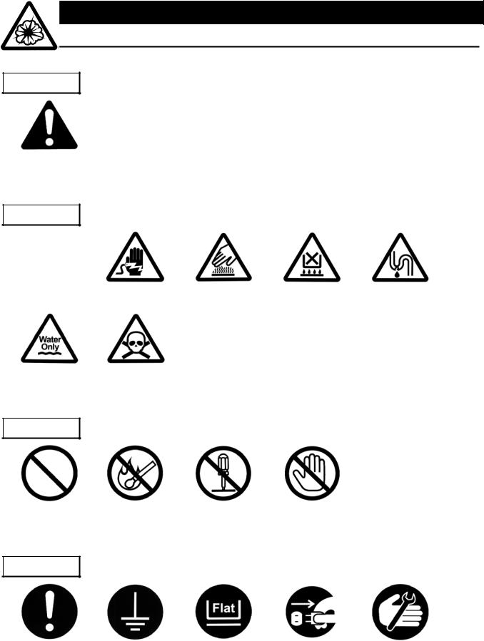
MEANING OF ILLUSTRATED SYMBOLS
Illustrated Symbols
Various symbols are used in this safety manual in order to use the unit without danger of injury and damage of the unit. A list of problems caused by ignoring the warnings and improper handling is divided as shown below.Be sure that you understand the warnings and cautions in this manual before operating the unit.
 WARNING!
 CAUTION!
If the warning is ignored, there is the danger of a problem that may cause a serious accident or even fatality.
If the caution is ignored, there is the danger of a problem that may cause injury/damage to property or the unit itself.
Meaning of Symbols
This symbol indicates items that urge the warning (including the caution). A detailed warning message is shown adjacent to the symbol.
This symbol indicates items that are strictly prohibited.
A detailed message is shown adjacent to the symbol with specific actions not to perform.
This symbol indicates items that should be always performed.
A detailed message with instructions is shown adjacent to the symbol.
1
Cautions in Using with Safety
Table of Illustrated Symbols
Warning
Warning, |
Warning, |
Warning, |
Warning, |
Warning, |
generally |
high voltage |
high temperature |
drive train |
explosive |
Caution
Caution, |
Caution, |
Caution, |
Caution, |
Caution, |
generally |
electrical shock |
scald |
no road heating |
not to drench |
Caution, |
Caution, |
water only |
deadly poison |
Prohibit
Prohibit, |
Prohibit, |
Prohibit, |
Prohibit, |
generally |
inflammable |
to disassemble |
to touch |
Compulsion
Compulsion, |
Compulsion, |
Compulsion, |
Compulsion, |
Compulsion, |
generally |
connect to the |
install on a flat |
disconnect the |
periodical |
|
grounding |
surface |
power plug |
inspection |
|
terminal |
|
|
|
2
Cautions in Using with Safety
Fundamental Matters of "WARNING!" and "CAUTION!"
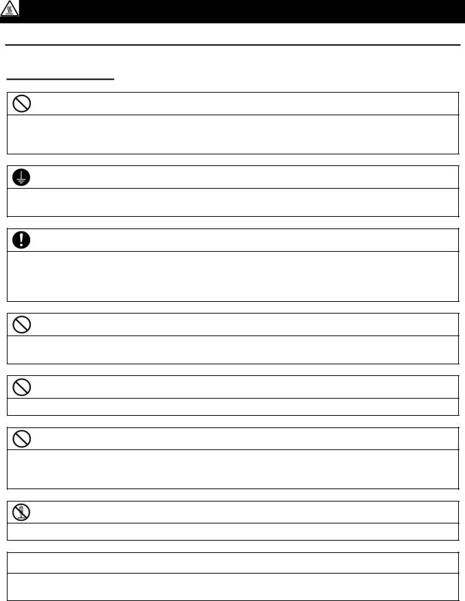
 WARNING!
Do not use this unit in an area where there is flammable or explosive gas
Never use this unit in an area where there is flammable or explosive gas. This unit is not explosion-proof. An arc may be generated when the power switch is turned on or off, and fire/explosion may result. (Refer to page 56 "List of Dangerous Substances".)
Always ground this unit
Always ground this unit on the power equipment side in order to avoid electrical shock due to a power surge.
If a problem occurs
If smoke or strange odor should come out of this unit for some reason, turn off the circuit breaker right away, and then disconnect the power plug or power terminal. Immediately contact a service technician for inspection. If this procedure is not followed, fire or electrical shock may result. Never perform repair work yourself, since it is dangerous and not recommended.
Do not use the power cord if it is bundled or tangled
Do not use the power cord if it is bundled or tangled. If it is used in this manner, it can overheat and fire may be caused.
Do not process, bend, wring, or stretch the power cord forcibly
Do not process, bend, wring, or stretch the power cord forcibly. Fire or electrical shock may result.
Substances that can not be used
Never use explosive substances, flammable substances and substances that include explosive or flammable ingredients in this unit. Explosion or fire may occur. (Refer to page 56 "List of Dangerous Substances".)
Do not disassemble or modify this unit
Do not disassemble or modify this unit. Fire or electrical shock or failure may be caused.
Do not get close to the vapor outlet / Do not block the outlet
The vapor outlet is provided on the left face of equipment. Do not put your hands or face close to the outlet. Do not block the outlet. A burn injury or equipment failure may result in.
3
Cautions in Using with Safety
Fundamental Matters of "WARNING!" and "CAUTION!"
 CAUTION!
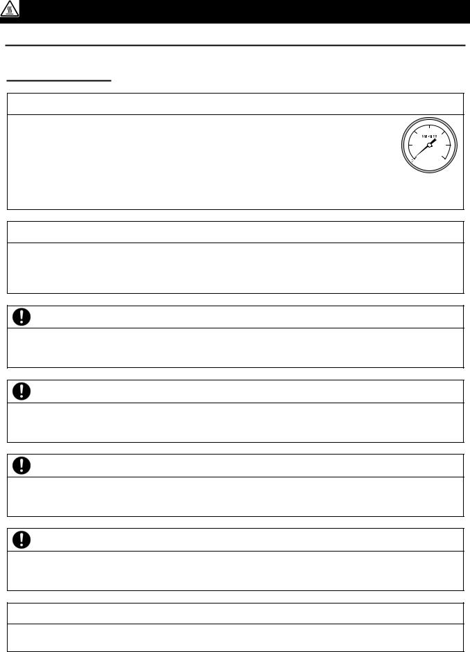
When opening the cover...
Make sure that the pressure of equipment has decreased to 0(zero) MPa before opening the cover. Generally the cover does not open due to the safety lock mechanism under the high pressure condition. The high-temperature and pressure vapor blows out if the cover is forced open under high pressure, which may cause a burn injury. A large amount of vapor blows out from inside of the chamber when opening the cover just after the sterilizing operation has completed (when the temperature inside the chamber is high). Do not put your hands and face close to the cover.
When draining water...
Make sure that the pressure of equipment has decreased to 0(zero) MPa before draining the sterilizing water. The hot water blows out if the valve is opened under high pressure. The sterilizing water remains very hot just after the sterilizing operation has completed even the pressure reading is 0(zero) MPa. Drain the water after it is sufficiently cooled down.
Do not touch the drain bottle during operation
A drain bottle, which contains hot water during and just after operation, is placed inside the door in the front face of equipment. To avoid a burn injury, remove the bottle after the water is sufficiently cooled down. Do not open the door during the operation of equipment.
Make sure to drain the water when the water level comes to the seal position
The hot water or vapor may blow out from the drain bottle if the equipment is operated with too much drain water (water level above the seal position). (Refer to 17 of “Precautions for continuous operation” in Page 13 for details.)
Securely fix the silicon plug of the drain bottle
Securely fix the silicon plug when installing the drain bottle. The hot water or vapor may blow out from the drain bottle if the equipment is operated with the plug loosen. (Refer to 6 of “Set the drain bottle” in Page 10 for details.)
Pour off the water inside the vapor cup after every operation
The cup becomes full with the water after the equipment is operated a few times. Pour off the water inside the cup after every operation. The hot water or vapor may blow out from the drain bottle if the cup is full with water. (Refer to 14 of “Attach the vapor cup” in Page 12 for details.)
Do not touch the hot section
Some sections on the equipment such as the circumference of cover or drain bottle are very hot during or just after the operation of equipment. Do not touch these sections to avoid burn injury.
4
Cautions in Using with Safety
Fundamental Matters of "WARNING!" and "CAUTION!"
When taking the sterile samples from the chamber...
Sufficiently remove the vapor inside the chamber before taking the sterile samples from the chamber. Wear heat-resistant leather gloves to take them from the chamber to protect your hands from high-temperature samples.
Do not touch the heat releasing outlet
Do not directly touch the heat releasing outlet located around the outer covering. The vapor may blow out from the safety valve by an accident during sterilizing operation. Do not block the outlet.
During a thunder storm
During a thunderstorm, turn off the power key immediately, then turn off the circuit breaker and the main power. If this procedure is not followed, fire or electrical shock may be caused.
When power failure occurs...
The lock lever on the cover goes into locked state for safety reasons when the power is turned off due to a power failure. The state is automatically cancelled when the power is turned on and the pressure inside the equipment decreases.
Do not operate the equipment without supplying sufficient amount of water
Do not operate the equipment without supplying sufficient amount of water. The heater is exposed to the open-air if the amount of water supplied is insufficient, which causes a deterioration or breakage of equipment. Make sure before operation that the appropriate amount of water is supplied inside the chamber. (Refer to 9 of “Pour water into the chamber” in Page 11 for details.)
Do not open the panel on the outer covering
Touching the interior portion of equipment may cause an electric shock, burn injury, fire disaster or equipment failure.
Do not touch the power plug with a wet hand
An electric shock may result in.
Do not place your hand over the top board
The hand may be stuck in the cover and injured.
5
Before Using This Unit
Requirements for Installation
1.Choose a proper place for installation
•Do not install this unit in a place where:
♦Rough or dirty surface.
♦Flammable gas or corrosive gas is generated.
♦Ambient temperature 35°C and above or 5°C and below.
♦Ambient temperature fluctuates violently.
♦There is direct sunlight.
♦There is excessive humidity and dust.
♦There is a constant vibration.
♦Not horizontal surface.
♦The power source is instable.
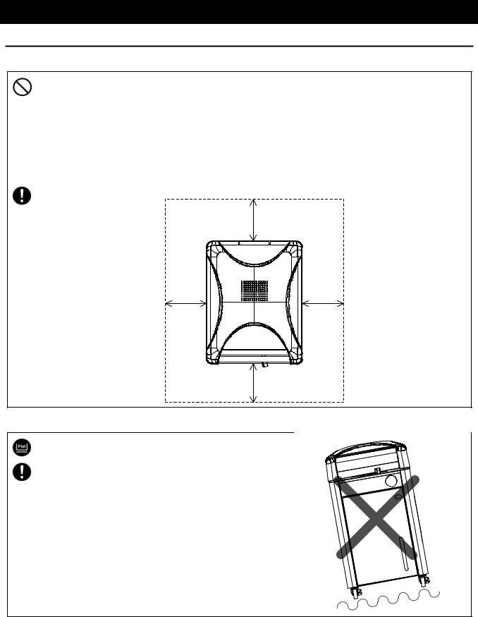
• Install this unit on a stable place with the space as shown below.
Back side |
30cm or more |
|
|
15cm |
15cm |
or |
or |
more |
more |
Front side
15cm or more
2.Installation on horizontal surface
•Use the equipment on the horizontal and firm place to keep the water inside the chamber horizontal. If the equipment tilts and the heater appears from the water surface, the temperature on the area above the water rises and a heater failure or operation stop due to water level detector function may occur.
•The weight of main unit is approximately 65 to 95kg. Carry and install the equipment carefully by two or more persons.
6
Before Using This Unit
Requirements for Installation
3.Before/after installing
•It may cause injure to a person if this unit falls down or moves by the earthquake and the impact. etc..To prevent, take measures that the unit cannot fall down, and not install to busy place.
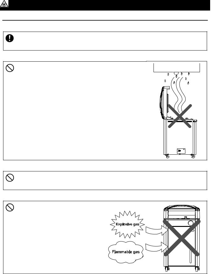
4.Do not install the equipment near alarm device
•The equipment releases large amount of vapor when the cover
is opened just after the operation is completed. Accordingly, do not install the equipment on the site over which electrical equipment especially an alarm device is provided over it.
5.Ventilate the equipment sufficiently
•Do not block the heat releasing outlets on the side face and back face of equipment during operation. The temperature inside the equipment rises, which may cause the deterioration or failure of equipment, accident, or fire disaster.
6.Do not use this unit in an area where there is flammable or explosive gas
•Never use this unit in an area where there is flammable or explosive gas.
This unit is not explosion-proof. An arc
may be generated when the power
switch is turned ON or OFF, and fire/explosion may result.
• To know about flammable or explosive gas, refer to page 56 “List of Dangerous Substances”.
7
Before Using This Unit
Requirements for Installation
7.Choose a correct power distribution board or receptacle
•Choose a correct power distribution board or receptacle that meets the unit’s rated electric capacity.
•Operating voltage range for respective equipment models are as follows.
SN200/300/500 and SQ500 models: AC100 to 120V SN210/310/510 and SQ510models: AC200 to 240V
Electric capacity: SN200: AC100V-120V 12.5A-15A, SN210: AC200V-240V 6.5A-7.5A SN300: AC100V-120V 16.5A-20A, SN310: AC200V-240V 8.5A-10A SN500: AC100V-120V 19.5A-23.5A, SN510: AC200V-240V 10A-12A SQ500: AC100V-120V 20.5A-24.5A, SQ510: AC200V-240V 10.5A-12.5A
NOTE)
There could be the case that the unit does not run even after turning ON the power. Inspect whether the voltage of the main power is lowered than the specified value, or whether other device(s) uses the same power line of this unit. If the phenomena might be found, change the power line of this unit to the other power line.
•Starburst connection with a branching receptacle or extended wiring with a cord reel lowers electrical power voltage, which may cause the degradation of refrigeration capability.
•Connect the unit to only the power supply. If it is connected to a gas pipe, water pipe or telephone line, an accident or malfunction may result.
8.Handling of power code
•Do not entangle the power cord. This will cause overheating and possibly a fire.
•Do not bend or twist the power cord, or apply excessive tension to it. This may cause a fire and electrical shock.
•Do not lay the power cord under a desk or chair, and do not allow it to be pinched in order to prevent it from being damaged and to avoid a fire or electrical shock.
•Keep the power cord away from any heating equipment such as a room heater. The cord's insulation may melt and cause a fire or electrical shock.
•If the power cord becomes damaged (wiring exposed, breakage, etc.), immediately turn off the power at the rear of this unit and shut off the main supply power. Then contact your nearest dealer for replacement of the power cord. Leaving it may cause a fire or electrical shock.
•Connect the power plug to the receptacle which is supplied appropriate power and voltage.
8
Before Using This Unit
Requirements for Installation
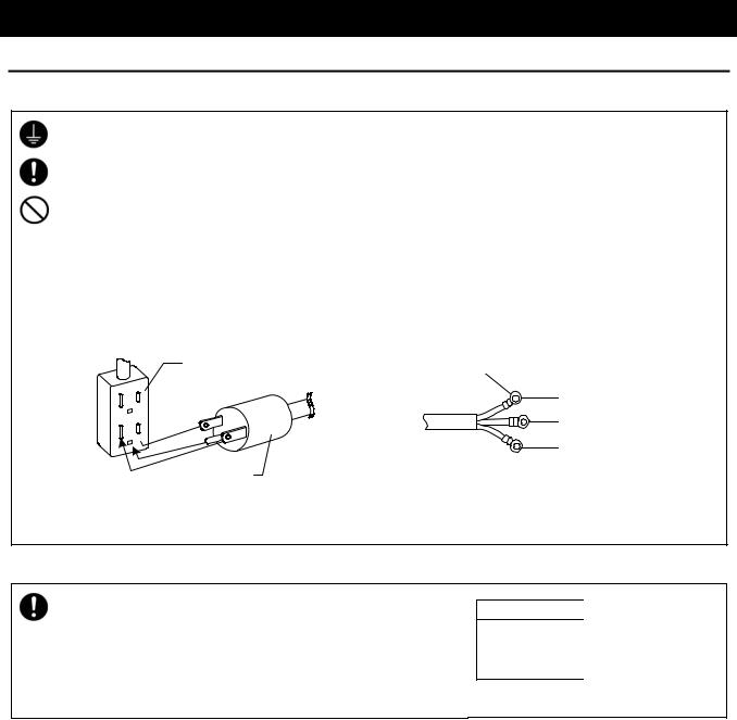
9.Always ground this unit
•Be sure to connect the earth wire (the green cable of power cord) to the grounding conductor or ground terminal to prevent accidents caused by electric leakage.
•Do not connect the earth wire to gas or water pipes. If not, fire disaster may be caused.
•Do not connect the earth wire to the ground for telephone wire or lightning conductor. If not, fire disaster or electric shock may be caused.
•Please consult your local electrical contractor for power connecting work.
•Do not use a branching receptacle, which may cause the heat generation.
•The D class earth connecting works is required if no ground terminal is provided. In this case, consult with the selling office where you purchased or our sales office.
•Securely connect it to the switchboard or outlet.
SN200
Earth connecting outlet
G
G
Power plug
An earth connecting outlet is recommended to be used.
SN210/300/310/500/510, SQ500/510
Rounded terminal
for M4
Green (to ground)
Black (to power supply)
White (to power supply)
These models do not include the power plug. Correctly connect the ground to fit with the power supply facility to be connected.
10. Connect the power cord paying attention to the color of each core wire
•When connecting the power cord, do check the breaker on the electric power equipment be "OFF". Note that SN210/300/310/500/510 and SQ500/510 do not equip with the power plug. Select and connect the appropriate plug or terminal corresponding to the power capacity that is adjusted to the status of the power supply equipment side.
Core Wire Color |
Interior Wiring |
Black |
Power Supply Side |
White |
Power Supply Side |
Green |
Ground Wire Side |
9
Before Using This Unit
Installation Procedure
1Determine the installation site
•If there is a bump on the floor, the casters may receive excessive load and get damaged. In this case, lift and move carefully by two or more persons.
Install the equipment referring to 1 to 5 of "Requirements for Installation" in Page 6.
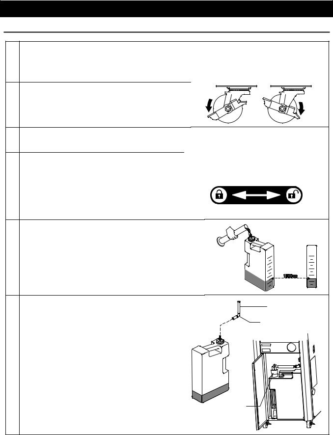
2 After the unit is placed in the desired position, |
Lock |
|
|
lock the stopper button of the casters |
Release |
||
|
|||
• Only the two casters on the front side of the unit |
|
|
|
are equipped with a stopper. |
|
|
3Connecting the power
•Connect the power referring to 7 to 10 of "Requirements for Installation" in Page 6.
4Open the cover
• Turn on the electric leakage breaker at the right |
Turn the lock lever to the left to close the cover. |
side of equipment and turn on the power to |
Turn the lock lever to the right to open the cover. |
open the cover. The safety lock is released |
|
and the cover can be opened. |
|
• Slide the lock lever on the cover to the right and |
|
grasp the handle of cover to open it. |
|
5 Pour water into the drain bottle
• Pour 1500cc of water into the drain bottle. The water is used to cool down the high-temperature vapor generated inside the chamber.
6 Set the drain bottle |
Exhaust hose |
|
• During operation, high-temperature vapor blows |
||
|
||
out from the equipment. Make sure to set the |
Silencer |
|
drain bottle. If the bottle is not set, the safety |
|
|
device (micro switch) functions to prevent the |
|
|
equipment from operating. |
|
Open the door in the front face of equipment.
Put the exhaust hose silencer into the drain bottle which contains 1500cc of water in it.
Set the bottle to the inside of door. Insert the exhaust hose into the bottle and fix the silicon
plug onto the opening of bottle.
Silicon plug
The micro switch is pressed and the equipment is ready to operate. The temperature display screen and time display screen are displayed.
10
Before Using This Unit
Installation Procedure
7Set the attached drainboard onto the bottom surface inside the chamber
• The drainboard stabilizes the sterile samples |
Set the drainboard |
|
inside the chamber as well as protects the |
||
horizontally. |
||
heater and sensor. Make sure to set it. |
||
|
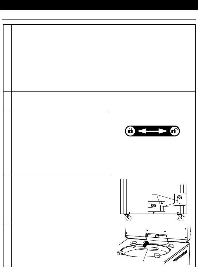
8 Close the drain valve |
Close |
•Close the drain valve at the bottom on the left side face of main unit. Water leak occurs if not fully closed, which may cause the burn injury or no-load (water) operation.
• |
Connect an appropriate hose (inner diameter: 12mm) to the |
Open |
||||
|
drain valve and lead it to the draining site. |
|
|
|
||
|
|
|
|
|||
9 Pour water into the chamber |
|
|
|
|||
• Before setting the sterile samples, pour water into the |
Water level |
|
||||
|
chamber to the water level gauge (notch) position. |
gauge |
|
|||
• Insufficient |
water may cause the no-load (water) |
|
|
|
||
|
operation. Check the water level every time before |
|
|
|
||
|
operation. |
Refill it before the level becomes too low. |
High |
|
||
|
Water is required to be poured at dissolution |
|
|
Low |
||
• |
operation, as well as sterilizing operation. |
|
|
|
||
When the water level lowers, the equipment detects |
|
|
|
|||
Water QTY for models |
||||||
|
an abnormality (“Err20”) and cuts off the heater. |
|||||
|
SN200/210 |
2200 2300 |
||||
|
Depending on the conditions of equipment, however, |
|||||
|
the detection requires too much time, which may |
SN300/310 |
3500 3700 |
|||
|
cause the |
heater deterioration. Refill water before |
|
|
|
|
|
SN500/510 |
3500 3700 |
||||
|
the water level becomes too low. |
|||||
|
SQ500/510 |
6300 6500 |
||||
• Refer to the right table for the quantity of water to be |
||||||
|
|
|
||||
|
refilled. |
|
|
|
|
|
10Use distillated or purified water for sterilizing water
•Fill distillated or purified water inside the chamber. Tap water may be used. Calculus generate inside the chamber when tap water is used. Frequent cleaning is therefore required.
•Do not use well water. It may cause the corrosion or dirt inside the chamber.
11
Before Using This Unit
Installation Procedure
11Set the sterile samples
•Set the samples to the chamber, putting them into the attached rack or cast (sold separately).
•Put the sample or sterilization bag into the chamber so they should not block or cover the sensor inside the chamber, exhaust outlet and end connection to pressure gauge. If they are blocked or covered, the vapor cannot be discharged and the equipment cannot be operated correctly. Do not spill the samples when taking them out from/putting them into the chamber. The failure in piping system, bad smell or dirt may result in.
•In case liquid such as medicinal solution or medium is sterilized, the amount of liquid should be 60% or less of the capacity of container. They may be boiled over if too much quantity is supplied.
•Widely open the opening of sterilization bag when used. If it is closed, the samples are insufficiently sterilized.
12Close the door before operation
•Make sure to close the door of equipment before operation. If the door is not fully closed, the drain bottle falls down and may cause a burn injury. Do not open the door during operation.
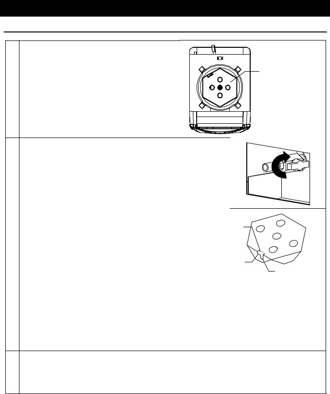
13 Close the cover |
Turn the lock lever to the left to close the cover. |
• Make sure that no foreign objects exist on the |
Turn the lock lever to the right to open the cover. |
packing of the cover and its contact area before |
|
closing the cover. If any foreign object exists, |
|
the vapor may leak from the inside. |
|
•The lock lever on the cover is held by the hook and does not move when the cover remains open.
•Fully close the cover and slide the lock lever on the cover to the left side. If it is closed inappropriately, the vapor blows out from the inside, which may cause a burn injury.
•Do not press the hook and operate the lock lever for purposes other than maintenance of equipment.
14Attach the vapor cup
•The equipment is equipped with a vapor cup to
prevent the vapor that generate during air purge
from becoming water droplet and dropping down Vapor cup onto the floor. Attach the cup onto the vapor
outlet on the left side face of equipment referring to the right figure. Make sure to pour off the water inside the vapor cup after every operation.
15Attach the droplet tray
•Attach the droplet tray to the equipment to
prevent the waterdrops that are made from vapor that generate during air purge from dropping
down from the packing onto the samples or onto the top board. Pour off the droplets inside the
tray periodically.
Droplet tray
12
Before Using This Unit
Installation Procedure
16Precautions for drainage
•Before draining the water, make sure that the pressure, equipment temperature and water temperature inside the chamber have decreased sufficiently.
17Precautions for continuous operation
• When operating the equipment continuously after sterilization is completed, leave the equipment for about 15 minutes with the cover opened to sufficiently lower the temperature inside the chamber and then close the cover. If the temperature is high, the cover may not close due to high internal pressure of chamber.
•Before operating the equipment again, check the water level of drain bottle by observing it from the observation window to make sure that it is below the level indicated by the drain level seal on the door. In case the water level of drain bottle is above the drain level seal, drain the water until the water level comes to 1500cc of the water level gauge, indicated on the side face of bottle. The hot water or vapor may blow out from the drain bottle if the equipment is operated with too much drain water (above the seal position).
13
Before Using This Unit
Installation Procedure
Reference Data
Sterilizing operation using disposal bag for biochemically dangerous object
Open the opening of sterilization bag so the vapor can be easily entered into it. Secure the bag with a wire rack so it should not fall down during operation.
The height of bag should be about two-thirds of chamber. If it is too high, the vapor cannot be easily entered into it, or it blocks the vapor outlet at the upper part of chamber, which may cause insufficient sterilization.
The preset temperature should be the upper temperature limit of bag to be used.
Sterilization
bag
The preset time varies depending on the quality and quantity of sterile samples. Refer to the following data for the preset time.
• Reference example of SN500 model at room temperature of 25
Sterile sample |
Sterilization temperature |
Sterilization time |
Note |
Gauze |
121 |
30 min. |
Five bolts of dry gauze |
|
|||
Petri dish |
121 |
40 min. |
30 Petri dish with a cover |
|
The data above, however, is used as reference. The actual sterile condition varies depending on the characteristics and quantity of samples or type of vessels to be used. Confirm the sterile condition using the biological indicator or chemical indicator.
14
Before Using This Unit
Installation Procedure
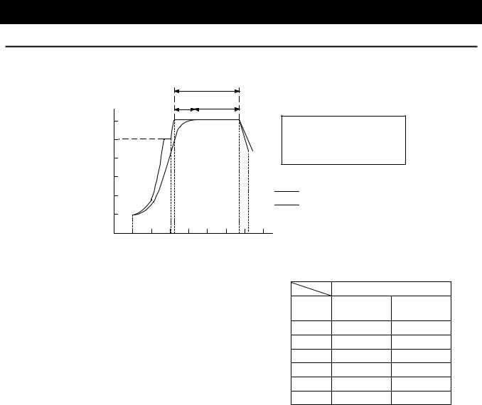
Time lag
a
b c
Saturated |
|
|
|
a= Preset sterilization time |
|
|
|
b= Time lag |
|
vapor |
|
|
|
|
|
|
|
c= sterilization time defined by the |
|
temperature |
|
|
|
|
|
|
|
|
Japanese Pharmacopoeia |
|
|
|
|
Temperature inside the chamber |
|
|
|
|
Water temperature |
|
|
|
|
Time |
When sterilizing liquid samples, a time lag (b) is made between the temperature inside the chamber and actual temperature of liquid by the time when the liquid temperature reaches the preset sterilization temperature. For this reason, a longer time than defined by the Japanese Pharmacopoeia (c) is required to completely sterilize the samples. Consequently, the actual preset sterilization time (a) should be set to be extended
The right table shows the time lag between the temperature inside the chamber and actual temperature of liquid (water). The table below shows the temperature rise and cooling time with no load (liquid).
Preset sterilization temperature:121 /room temperature: 25 (using conical flask)
Time lag
Load SN200/210 SN500/510
/300/310 SQ500/510
500cc 20min. 20min.
1000cc 20min. 20min.
2000cc 25min. 25min.
3000cc 25min. 25min.
4000cc 25min. 25min.
5000cc 30min. 30min.
Necessary time for sterilization
At room temperature of 25 Course: apparatus sterilization/forced cooling: OFF)
|
|
Sterilization |
|
Time required |
|
|||
|
|
conditions |
|
Total time |
||||
|
Water |
|
|
|
||||
|
|
|
Air |
|
|
|||
Model |
|
Preset |
Pressurizing |
Cooling-down |
required |
|||
temperature |
Preset |
|||||||
|
time |
purge |
time |
time |
+ + + |
|||
|
|
temperature |
time |
|||||
|
|
|
|
|
|
|||
|
|
|
|
|
||||
|
|
|
|
|
|
|
||
|
|
|
|
|
|
|
|
|
SN200/210 |
25 |
121 |
20min. |
23min. |
16min. |
29min. |
88min. |
|
|
|
|
|
|
|
|
||
25 |
126 |
15min. |
23min. |
20min. |
33min. |
91min. |
||
|
||||||||
SN300/310 |
25 |
121 |
20min. |
25min. |
20min. |
31min. |
96min. |
|
25 |
126 |
15min. |
25min. |
22min. |
35min. |
97min. |
||
|
||||||||
|
|
|
|
|
|
|
|
|
SN500/510 |
25 |
121 |
20min. |
25min. |
20min. |
33min. |
98min. |
|
|
|
|
|
|
|
|
||
25 |
126 |
15min. |
25min. |
22min. |
37min. |
99min. |
||
|
||||||||
SQ500/510 |
25 |
121 |
20min. |
30min. |
20min. |
36min. |
106min. |
|
25 |
126 |
15min. |
31min. |
24min. |
40min. |
110min. |
||
|
||||||||
|
|
|
|
|
|
|
|
|
15
Description and Function of Each Part
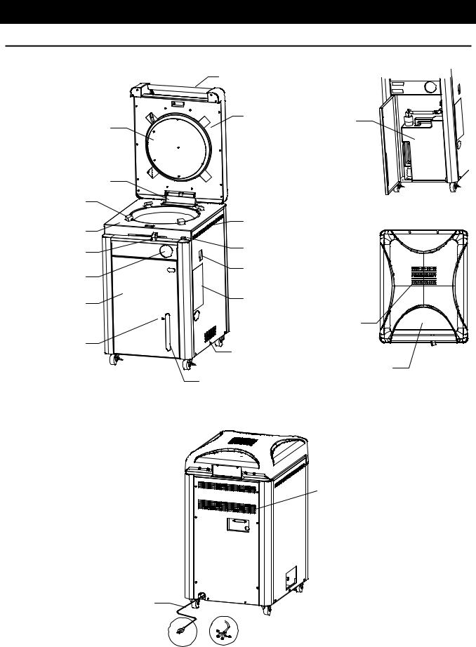
Main Unit
Front/upper view |
Handle |
|
|
Cover |
Drain bottle |
Packing |
|
|
|
|
Droplet |
tray |
Cover lock |
|
Top board |
Heat releasing outlet |
|
|
Cover locking lever |
Hook |
Pressure gauge |
Earth leakage breaker |
|
|
Door |
Rating notice sticker |
|
|
|
Heat releasing outlet |
Drain level scale |
Intake of forced cooling fan |
|
Control panel
Water level observation window for drain bottle
Rear view
 Heat releasing outlet
External output terminal (optional) 
Drain valve, Vapor cup,
 and Vapor outlet
Power cord
 Caster
SN200 SN210/300/310/500/510
SQ500/510
16

Description and Function of Each Part
Inner structure
Exhaust solenoid valve (F)
Exhaust solenoid valve (S)
Bottle sensor 
Fan motor 
Full lock
Chamber temperature sensor 
Back face
Option port (x2)
Back face
Chamber
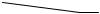 Safety valve
Option port (x2)
Vapor outlet
Vapor cup
Drain valve
17
 Loading...