


Forced Convection
Constant Temperature Oven
Model
DNF 400/410/600
610/810/910
Instruction Manual
- Version 5 -
zThank you for purchasing "Forced Convection Constant Temperature Oven, DNF Series" of Yamato Scientific Co., Ltd.
zTo use this unit properly, read this "Instruction Manual" thoroughly before using this unit.
Keep this instruction manual around this unit for referring at anytime.
 WARNING!:
Carefully read and thoroughly understand the important warning items described in this manual before using this unit.
Yamato Scientific Co. LTD.

|
|
Contents |
Cautions in Using with Safety................................................................ |
1 |
|
• |
Explanation.................................................................................................................... |
1 |
• Table of Illustrated Symbols .......................................................................................... |
2 |
|
• Fundamental Matters of "WARNING!" and "CAUTION!"............................................... |
3 |
|
Before Using this unit............................................................................. |
4 |
|
• |
Requirements for Installation......................................................................................... |
4 |
Description and Function of Each Part ................................................. |
9 |
|
• |
Main Unit ....................................................................................................................... |
9 |
• |
Control Panel............................................................................................................... |
12 |
Operation Method ................................................................................. |
13 |
|
• Key Operation Chart of Mode Setting and Program Registering ................................ |
13 |
|
• Operation Mode and Function List .............................................................................. |
14 |
|
• |
Fixed Temperature Operation...................................................................................... |
15 |
• |
Auto Stop Operation.................................................................................................... |
17 |
• |
Auto Start Operation.................................................................................................... |
20 |
• |
Program Operation...................................................................................................... |
22 |
• |
Input Program.............................................................................................................. |
25 |
• Input Program; Set the Temperature ........................................................................... |
27 |
|
• Input Program; Set the Time ....................................................................................... |
28 |
|
• Input Program; Set the Fan Rotation Speed ............................................................... |
29 |
|
• Input Program; Set the Repeat Initiating Step ............................................................. |
30 |
|
• Input Program; Set the Repeat Count ......................................................................... |
31 |
|
• Input Program; Insert Step .......................................................................................... |
32 |
|
• |
Input Program; Add Step ............................................................................................. |
33 |
• Input Program; Delete Step......................................................................................... |
34 |
|
• Input Program; End Program ...................................................................................... |
35 |
|
• |
Program Creation Method ........................................................................................... |
36 |
• |
Programming Preparation Form.................................................................................. |
42 |
• Set the Timer Mode ..................................................................................................... |
43 |
|
• Set the Key Lock Mode ............................................................................................... |
44 |
|
• Set the Buzzer Mode................................................................................................... |
45 |
|
• |
Calibration Offset Function.......................................................................................... |
46 |
• |
Integrating Operation Time.......................................................................................... |
47 |
• |
Set Clock..................................................................................................................... |
48 |
• Set Fan Operation at Wait State.................................................................................. |
50 |
|
• Set the Fan Rotation Speed ........................................................................................ |
51 |
|
• Set the Communication Lockout Mode (Optional accessory) ..................................... |
52 |
|
• How to Operate the Damper ....................................................................................... |
53 |
|
• The Independent Overheating Prevention Device ...................................................... |
54 |
|
• Temperature Rise/Fall Data (Reference Data) ............................................................ |
55 |
|
|
Handling Precautions ........................................................................... |
56 |
|
Maintenance Method............................................................................. |
57 |
|
• Daily Inspection and Maintenance .............................................................................. |
57 |
Long storage and disposal................................................................... |
58 |
|
|
• When not using this unit for long term / When disposing ............................................ |
58 |
In the Event of Failure… ....................................................................... |
59 |
|
|
• Safety Device and Error Code..................................................................................... |
59 |
|
• Trouble Shooting ......................................................................................................... |
61 |
After Service and Warranty .................................................................. |
62 |
|
|
Specification.......................................................................................... |
63 |
|
Wiring Diagram...................................................................................... |
65 |
|
Replacement Parts Table...................................................................... |
69 |
|
Reference............................................................................................... |
71 |
|
• List of Dangerous Substances .................................................................................... |
71 |
Cautions in Using with Safety
Explanation
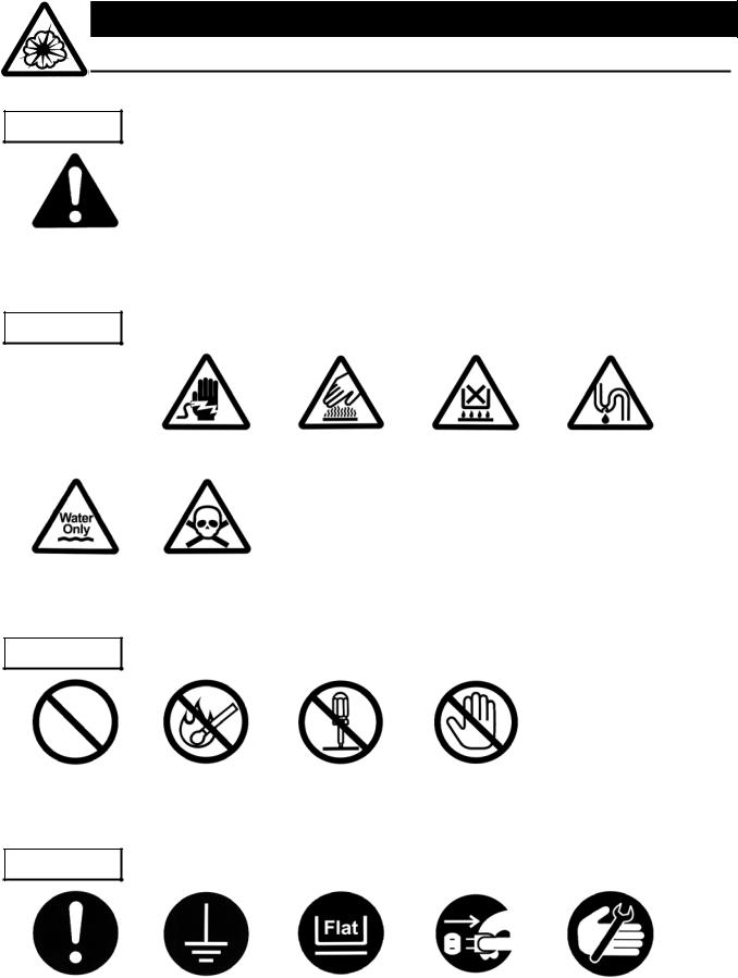
MEANING OF ILLUSTRATED SYMBOLS
Illustrated Symbols
Various symbols are used in this safety manual in order to use the unit without danger of injury and damage of the unit. A list of problems caused by ignoring the warnings and improper handling is divided as shown below.Be sure that you understand the warnings and cautions in this manual before operating the unit.
 WARNING!
 CAUTION!
If the warning is ignored, there is the danger of a problem that may cause a serious accident or even fatality.
If the caution is ignored, there is the danger of a problem that may cause injury/damage to property or the unit itself.
Meaning of Symbols
This symbol indicates items that urge the warning (including the caution). A detailed warning message is shown adjacent to the symbol.
This symbol indicates items that are strictly prohibited.
A detailed message is shown adjacent to the symbol with specific actions not to perform.
This symbol indicates items that should be always performed.
A detailed message with instructions is shown adjacent to the symbol.
1
Cautions in Using with Safety
Table of Illustrated Symbols
Warning
Warning, |
Warning, |
Warning, |
Warning, |
Warning, |
generally |
high voltage |
high temperature |
drive train |
explosive |
Caution
Caution, |
Caution, |
Caution, |
Caution, |
Caution, |
generally |
electrical shock |
scald |
no road heating |
not to drench |
Caution, |
Caution, |
water only |
deadly poison |
Prohibit
Prohibit, |
Prohibit, |
Prohibit, |
Prohibit, |
generally |
inflammable |
to disassemble |
to touch |
Compulsion
Compulsion, |
Compulsion, |
Compulsion, |
Compulsion, |
Compulsion, |
generally |
connect to the |
install on a flat |
disconnect the |
periodical |
|
grounding |
surface |
power plug |
inspection |
|
terminal |
|
|
|
2
Cautions in Using with Safety
Fundamental Matters of "WARNING!" and "CAUTION!"
 WARNING!
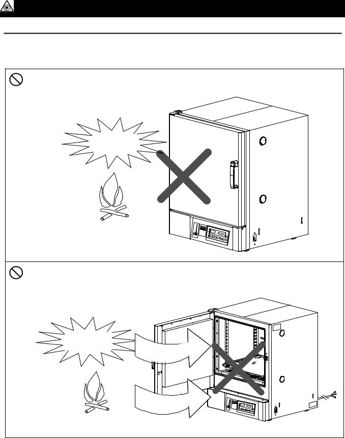
Do not use this unit in an area where there is flammable or explosive gas
Never use this unit in an area where there is flammable or explosive gas. This unit is not explosion-proof. An arc may be generated when the power switch is turned on or off, and fire/explosion may result. (Refer to page 71 "List of Dangerous Substances".)
Always ground this unit
Always ground this unit on the power equipment side in order to avoid electrical shock due to a power surge.
If a problem occurs
If smoke or strange odor should come out of this unit for some reason, turn off the power key right away, and then turn off the circuit breaker and the main power. Immediately contact a service technician for inspection. If this procedure is not followed, fire or electrical shock may result. Never perform repair work yourself, since it is dangerous and not recommended.
Do not use the power cord if it is bundled or tangled
Do not use the power cord if it is bundled or tangled. If it is used in this manner, it can overheat and fire may be caused.
Do not process, bend, wring, or stretch the power cord forcibly
Do not process, bend, wring, or stretch the power cord forcibly. Fire or electrical shock may result.
Substances that can not be used
Never use explosive substances, flammable substances and substances that include explosive or flammable ingredients in this unit. Explosion or fire may occur. (Refer to page 71 "List of Dangerous Substances".)
Do not disassemble or modify this unit
Do not disassemble or modify this unit. Fire or electrical shock or failure may be caused.
Do not touch high-temperature parts
The inside of the body or the door may become hot during and just after operation. It may cause burns.
 CAUTION!
During a thunder storm
During a thunderstorm, turn off the power key immediately, then turn off the circuit breaker and the main power. If this procedure is not followed, fire or electrical shock may be caused.
3

Before Using this unit
Requirements for Installation
 WARNING!
1.Always ground this unit
•The DNF400 and DNF600 types use a 100V power source.
•The DNF600 type does not contain a power plug. Please consult your local electrical contractor for power connecting work.
•The DNF410, DNF610, DNF810 and DNF910 types use a single-phase 200V power source. Please consult your local electrical contractor for power connecting work.
•Be sure to connect the earth wire (the green cable of power cord) to the grounding conductor or ground terminal to prevent accidents caused by electric leakage.
•Do not connect the earth wire to gas or water pipes. If not, fire disaster may be caused.
•Do not connect the earth wire to the ground for telephone wire or lightning conductor. If not, fire disaster or electric shock may be caused.
•Do not use a branching receptacle, which may cause the heat generation.
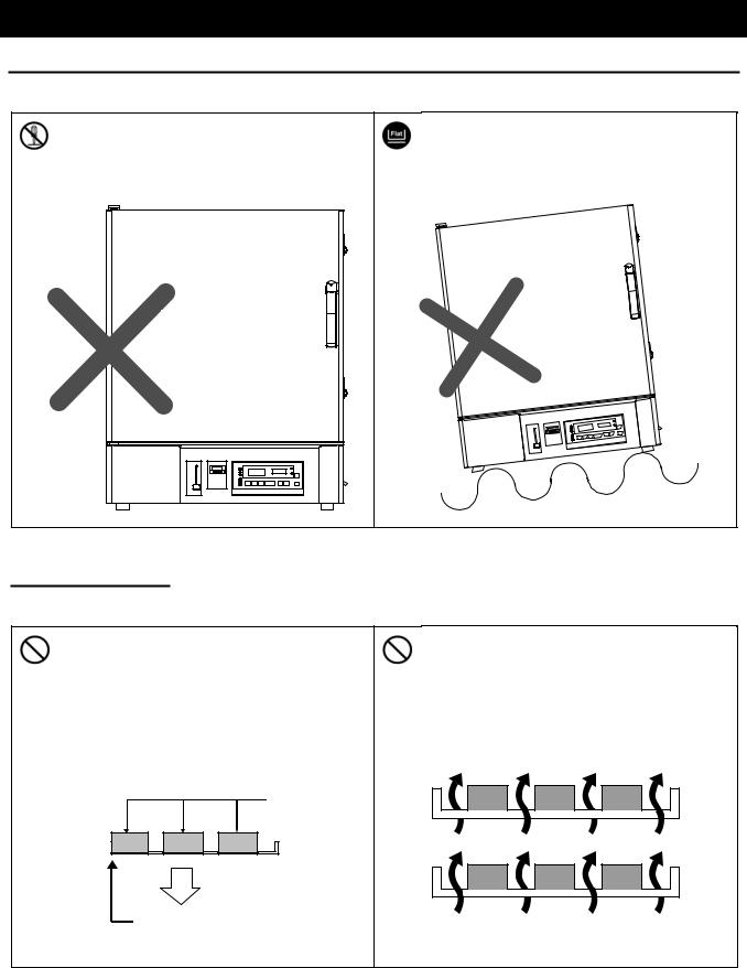
2.Choose a proper place for installation
•Do not install this unit in a place where:
♦Rough or dirty surface.
♦Flammable gas or corrosive gas is generated.
♦Ambient temperature exceeds 35°C.
♦Ambient temperature fluctuates violently.
♦There is direct sunlight.
♦There is excessive humidity and dust.
♦There is a constant vibration.
•Install this unit on a stable place with the space as shown below. The exhausted opening is provided on the back surface. Keep away from it during operation.
|
30cm or more |
30cm |
30cm |
or |
or more |
more |
|
DNF400/410 |
|
65cm or more |
|
DNF600/610 |
|
80cm or more |
|
|
30cm or more |
30cm |
15cm |
|
|
or more |
or |
|
more |
80cm or more
DNF400/410/600/610
DNF810
DNF910
30cm or more
30cm |
30cm or more |
|
or more
70cm or more
4
Before Using this unit
Requirements for Installation
3. Do not use this unit in an area where there is flammable or explosive gas
(Refer to page 71 "List of Dangerous Substances".)
•Never use this unit in an area where there is flammable or explosive gas. This unit is not explosion-proof. An arc may be generated when the power switch is turned ON or OFF, and fire/explosion may result.
Explosive
gas
Flammable gas
•Never use explosive substances, flammable substances and substances that include explosive or flammable ingredients in this unit. Explosion or fire may occur.
Explosive substance
Flammable substance
5
Before Using this unit
Requirements for Installation
4. Do not modify |
5. Installation on horizontal surface |
•Modification of this unit is strictly prohibited. This could cause a failure.
Do not modify
•Set this unit to the flattest place. Setting this unit on rough or slope place could cause the vibration or noise, or cause the unexpectible trouble or malfunction.
 CAUTION!
6. Do not make an overload |
7. Do not set samples in close formation |
•The withstand load of shelf is 15kguniform load Set the samples apart each other.
Samples
15Kg
Shelf
•The temperature in furnace cannot be controlled if too much samples are set there. Make sure to use the shelf and set samples apart each other so as to make the free space of 30% or more to the furnace to acquire accuracy of temperature.
Make the free space of 30% or more
6
Before Using this unit
Requirements for Installation
8.Do not use corrosive sample
•Stainless steel SUS304 is used for the main hot-air path; however, it may be corroded by strong acid etc. And the door packing made of silicon rubber may be corroded by some kind of solvent, e.g. alkaline, oil, halogen etc. Do not use the sample includes those.
9.Choose a correct power distribution board or receptacle
•Choose a correct power distribution board or receptacle that meets the unit’s rated electric capacity.
Electric capacity: |
|
|
|
|
DNF400: |
100V AC, 13.5A |
DNF410: |
1φ200V AC, 7A |
DNF810: 1φ200V AC, 15A |
DNF600: |
100V AC, 16A |
DNF610: |
φ |
DNF910: 1φ200V AC, 18A |
|
|
1 200V AC, 8A |
|
|
NOTE)
There could be the case that the unit does not run even after turning ON the power. Inspect whether the voltage of the main power is lowered than the specified value, or whether other device(s) uses the same power line of this unit. If the phenomena might be found, change the power line of this unit to the other power line. Please consult your dealer or a local electrical contractor for the connection of DNF600 and devices that use a single-phase 200V power source.
10.Handling of power code
•Do not entangle the power cord. This will cause overheating and possibly a fire.
•Do not bend or twist the power cord, or apply excessive tension to it. This may cause a fire and electrical shock.
•Do not lay the power cord under a desk or chair, and do not allow it to be pinched in order to prevent it from being damaged and to avoid a fire or electrical shock.
•Keep the power cord away from any heating equipment such as a room heater. The cord's insulation may melt and cause a fire or electrical shock.
•If the power cord becomes damaged (wiring exposed, breakage, etc.), immediately turn off the power at the rear of this unit and shut off the main supply power. Then contact your nearest dealer for replacement of the power cord. Leaving it may cause a fire or electrical shock.
•Connect the power plug to the receptacle which is supplied appropriate power and voltage.
11.Before/after installing
•It may cause injure to a person if this unit falls down or moves by the earthquake and the impact. etc..To prevent, take measures that the unit cannot fall down, and not install to busy place.
•Touching the unit may cause a burn during and just after the operation. To prevent, take measures that putting up a notice of operating etc..
•Make sure to lock the caster for DNF810 and DNF910 types.
7
Before Using this unit
Requirements for Installation
12.Setting of the shelf and sample
•The number of shelves attached varies depending on the type of product (2 to 8).One of them (two for DNF910) is previously fixed on the lowermost stand of bracket supporter with screws at factory shipment. Set the other shelves in place in furnace as necessary.
•One of the shelves is fixed on the lowermost stand of bracket supporter with screws at factory shipment. The temperature of the current plate and its adjacence is usually higher than the setting temperature because the heater is provided under it, which may cause burn of sample or fire disaster if the sample is directly put on the current plate. Do not shut the slit on near side of current plate with samples because it is an inlet slit on the circuration circuit of hot air,
with samples. To prevent such accidents, the shelf is fixed with a screw as shown in the figure. Be sure to provide sufficient space between the current plate and sample in case the shelf must be removed due to the shape of sample. Do not put the sample directly on the current plate.
Bracket supporter
Bracket
Current plate
Screw
Screw
Shelf
8
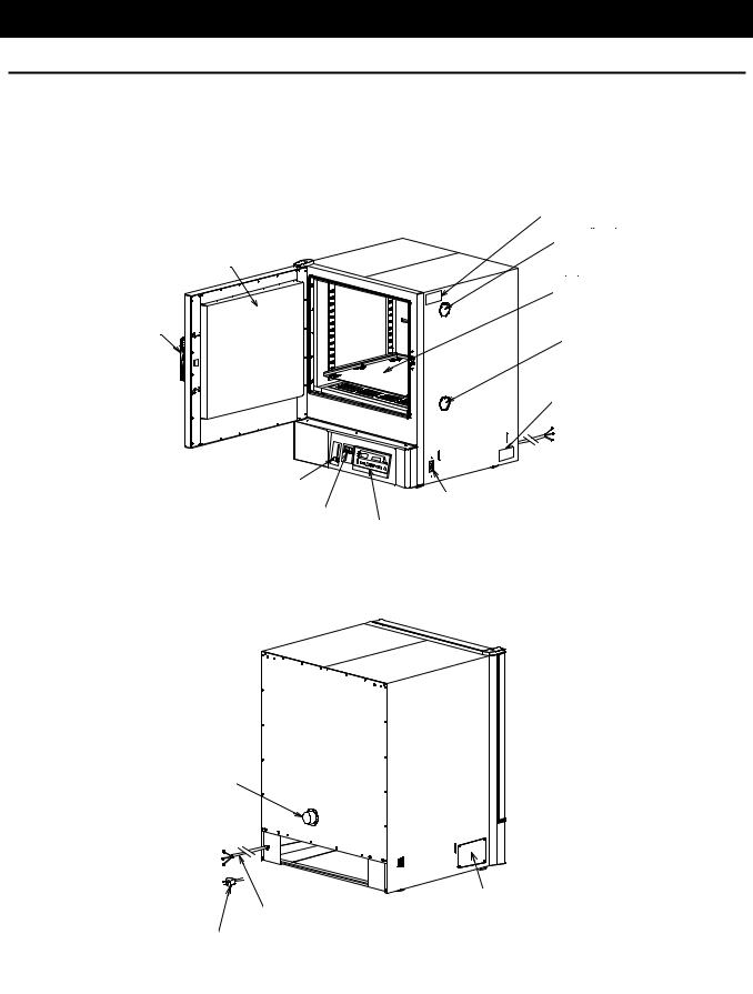
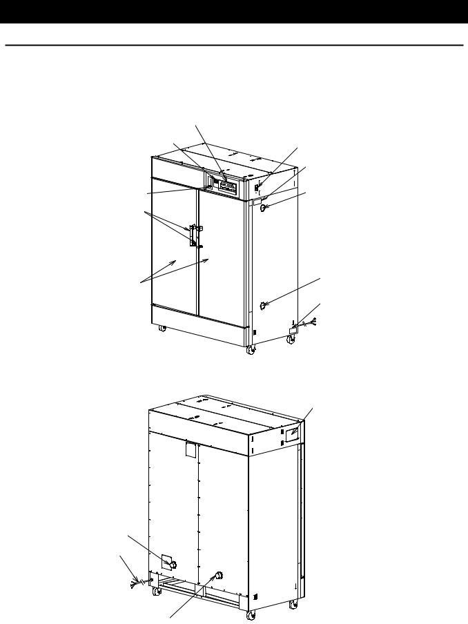
Description and Function of Each Part
Main Unit
DNF400/410/600/610
Front view
Production plate
Cable port
Door
Shelf
Door handle |
Intake opening |
|
Specification plate
Damper knob
Earth leakage breaker
Overheating prevention device
Control panel
Rear view
Exhaust opening
Optional accessory attaching port
Power code
(DNF410/600/610)
Power code (DNF400)
9
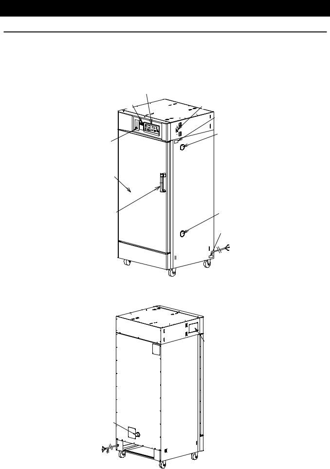
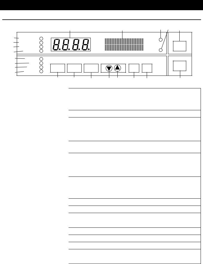
Description and Function of Each Part
Main Unit
DNF810
Front view
Control panel
Overheating prevention device Earth leakage breaker
Production plate
Cable port
Damper knob
Door
Door handle |
Intake opening |
Specification plate
Rear view
Optional accessory attaching port
Exhaust opening
Power code
10
Description and Function of Each Part
Main Unit
DNF910
Front view
Control panel |
|
Overheating prevention device |
Earth leakage breaker |
|
|
|
Production plate |
Damper knob |
Cable port |
Door handle |
|
Intake opening
Door
Specification plate
Rear view
Optional accessory attaching port
Exhaust opening
Power code
Exhaust opening
11
Description and Function of Each Part
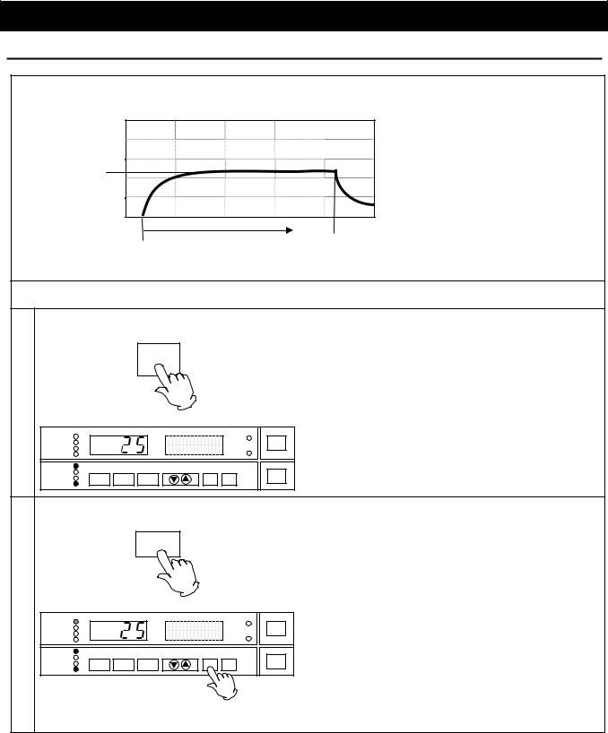
Control Panel
|
|
|
1 |
|
|
2 |
|
3 |
4 |
21 |
5 |
FIXED TEMP |
|
|
|
|
|
|
DOOR |
|
|
6 |
|
|
|
|
|
|
|
|
||
AUTO STOP |
|
|
|
|
|
|
|
|
|
|
7 |
AUTO START |
|
|
|
|
|
|
TROUBLE |
|
SUBMENU |
|
|
|
|
|
|
|
|
|||
8 |
PROGRAM |
|
|
|
|
|
|
|
|
|
|
|
|
|
|
|
|
|
|
||
9 |
STANDBY |
|
|
|
|
|
|
|
|
|
10 |
END |
|
|
|
|
|
|
|
|
POWER |
11 |
HEATER |
FUNCTION |
PROGRAM |
MENU |
|
|
ENTER |
CANCEL |
|
|
|
|
|
|
|||||||
12 |
FAN |
|
|
|
|
|
|
|
|
|
|
|
|
|
|
|
|
|
|
|
|
|
|
13 |
14 |
15 |
16 |
17 |
18 |
19 |
|
20 |
1 |
Main Display |
Displays the measured temperature and error code. |
2 |
Sub Display |
Displays the operation and setting information. |
|
|
Lights while the door is opened. (Disabled in this unit.) |
3 |
DOOR lamp |
|
|
|
Blinks when a trouble occurs. |
4 |
TROUBLE Lamp |
|
|
|
Lights while the fixed temperature operation is running. |
5 |
FIXED TEMP lamp |
|
|
|
Blinks while the choosing operation mode. |
6 |
AUTO STOP Lamp |
Lights while the auto stop operation is running. |
|
|
Blinks while choosing the operation mode. |
7 |
AUTO START Lamp |
Lights while the auto start operation is running. |
|
|
Blinks while choosing the operation mode. |
8 |
PROGRAM Lamp |
Lights while the program operation is running. |
|
|
Blinks while choosing the operation mode. |
9 |
STANDBY Lamp |
Lights while the device is in standby state. |
|
|
Blinks while the device is in startup wait state. |
10 |
END Lamp |
Blinks at end of the autostop or program operation. |
|
|
Lights while the heater works. |
11 |
HEATER Lamp |
|
|
|
Lights while the fan works. |
12 |
FAN Lamp |
|
|
|
Starts the function menu. |
13 |
FUNCTION Key |
|
|
|
Starts the program menu. |
14 |
PROGRAM Key |
|
|
|
Starts the operation menu. |
15 |
MENU Key |
|
|
|
Lowers down the setting value. |
16 |
▼(Down) Key |
|
|
|
Rises up the setting value. |
17 |
▲(Up) Key |
|
|
|
Settles the inputted value/item. |
18 |
ENTER Key |
|
|
|
Cancels the current inputting. |
19 |
CANCEL Key |
|
|
|
Turns ON/OFF the power. |
20 |
POWER Key |
|
|
|
Used for operation with the optional accessory. |
21 |
SUBMENU Key |
|
|
|
|
12

Operation Method
Key Operation Chart of Mode Setting and Program Registering
13

Operation Method
Operation Mode and Function List
The operation mode consists of the following four modes.
No. |
Name |
|
Description |
Page |
|
|
|
|
|
1. |
Fixed Temperature Operation |
Controls temperature with fixed temperature. |
15 |
|
|
|
|
|
|
2. |
Auto Stop Operation |
Stops operation at specified time. |
17 |
|
|
|
|
|
|
3. |
Auto Start Operation |
Starts operation at specified time. |
20 |
|
|
|
|
|
|
4. |
Program Operation |
Starts program operation at specified time. |
22 |
|
|
|
|
|
|
The function menus are listed below. |
|
|
|
|
|
|
|
|
|
|
Name |
|
Function |
Page |
|
|
|
|
|
Timer Mode |
|
Sets timer mode. |
43 |
|
|
|
|
|
|
Key Lock Mode |
|
Sets key lock mode. |
44 |
|
|
|
|
|
|
Buzzer Mode |
|
Sets buzzer mode. |
45 |
|
|
|
|
|
|
Calibration Offset |
|
Sets calibration offset temperature. |
46 |
|
|
|
|
|
|
Integrating Operation Time |
|
Displays integrating operation time. |
47 |
|
|
|
|
|
|
Date/Time |
|
Sets date and time. |
48 |
|
|
|
|
|
|
Fan in Standby State |
|
Sets start/stop of fan in standby state. |
50 |
|
|
|
|
|
|
Fan Rotation Speed |
|
Sets fan rotation speed. |
51 |
|
|
|
|
||
Communication Lockout Mode (Optional) |
Sets communication lockout mode. |
52 |
||
|
|
|
|
|
14
Operation Method
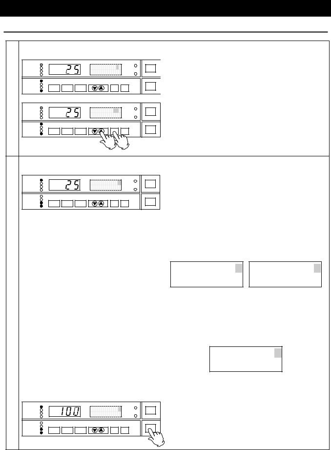
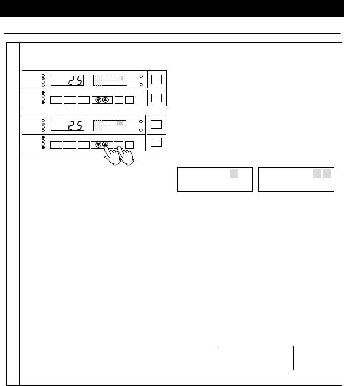
Fixed Temperature Operation
Start the operation from turning on the power shown in the figure, and continue the operation under the setting temperature unless turning off the power.
SV |
|
|
SV: Setting temperature |
|
|
|
|
||
|
|
|
t: Time |
|
|
t |
▲ |
|
|
▲ |
|
|
|
|
START |
|
STOP |
|
|
Setting of the Fixed Temperature Operation |
|
|
|
|
1 Turn on the power |
• |
Turn on the power switch of the unit (earth leakage |
||
|
|
breaker). Pressing the POWER key turns on the |
||
POWER |
|
power. |
The Main Display indicates the |
|
|
|
temperature in furnace. |
The Sub Display |
|
|
|
indicates "Standby" and the STANDBY lamp lights |
||
|
|
on. (Hereafter, this state is called the "standby |
||
|
|
state".) |
|
|
FIXED TEMP |
|
|
|
Standby |
DOOR |
• |
The FAN lamp lights on and the fan rotates when |
|
AUTO STOP |
|
|
|
TROUBLE |
SUBMENU |
"Standby" is displayed. |
Refer to the page 50 to |
|
PROGRAM |
|
|
2002/01/01 12:00 |
|
||||
AUTO START |
|
|
|
|
|
|
|
|
STANDBY |
|
|
|
|
|
|
stop the rotation of fan. |
|
END |
|
|
|
|
|
POWER |
|
|
HEATER |
FUNCTION |
PROGRAM |
MENU |
ENTER |
CANCEL |
|
|
|
FAN |
|
|
|
|||||
|
|
|
|
|
|
|
|
|
2 Select operation mode |
Pressing the MENU key displays the operation |
|
|
mode selection screen. |
|
MENU |
The Sub Display on the operation mode selection |
|
|
||
|
screen displays the name of operation mode |
|
|
currently selected with blinking. |
The |
|
corresponding operation mode lamp blinks at the |
|
|
same time. |
|
AUTO STOP |
|
|
|
Fixed TEMP OPR |
|
SUBMENU |
Keep pressing the MENU key until the fixed |
|
FIXED TEMP |
|
|
|
|
DOOR |
|
|
|
AUTO START |
|
|
|
Select OPR mode |
TROUBLE |
|
temperature operation mode is displayed. |
|
PROGRAM |
|
|
|
|||||
|
|
|
|
|
||||
STANDBY |
FUNCTION |
PROGRAM |
MENU |
ENTER |
CANCEL |
|
Press the ENTER key. |
The fixed temperature |
HEATER |
|
|||||||
END |
|
|
|
|
|
POWER |
|
|
|
|
|
|
|
|
|
|
|
FAN |
|
|
|
|
|
|
operation mode is decided. |
|
|
|
|
|
|
|
|
||
|
|
|
|
|
|
|
The fixed temperature operation is selected at the |
|
|
|
|
|
|
|
|
initial setting of unit. The operation mode carried |
|
|
|
|
|
|
|
|
out last is selected in case other than it. |
|
15
Operation Method
Fixed Temperature Operation
3 |
Set temperature |
|
|
|
|
|
The |
setting |
temperature |
input |
screen |
|
is |
||||||||
|
|
|
|
|
Set TEMP |
0 |
|
|
displayed. |
The |
Sub |
Display |
indicates |
"Set |
|||||||
|
AUTO STOP |
|
|
|
|
SUBMENU |
TEMP" and the numeric character that indicates |
||||||||||||||
|
FIXED TEMP |
|
|
|
|
|
DOOR |
|
|
|
|
|
|
|
|
|
|
|
|
|
|
|
AUTO START |
|
|
|
Fixed TEMP OPR |
TROUBLE |
|
temperature blinks. |
|
|
|
|
|
|
|
|
|||||
|
PROGRAM |
|
|
|
|
|
|
|
|
|
|
|
|
|
|
|
|
||||
|
|
|
|
|
|
|
|
|
|
|
|
|
|
|
|
|
|
|
|
||
|
STANDBY |
FUNCTION |
PROGRAM |
MENU |
|
ENTER |
CANCEL |
POWER |
Set the temperature using the "▲▼". |
|
|
|
|||||||||
|
HEATER |
|
|
|
|
||||||||||||||||
|
END |
|
|
|
|
|
|
|
|
|
|
|
|
|
|
|
|
|
|
|
|
|
FAN |
|
|
|
|
|
|
|
Press the ENTER key to decide the temperature |
||||||||||||
|
|
|
|
|
|
|
|
|
|||||||||||||
|
FIXED TEMP |
|
|
|
Set TEMP |
100 |
DOOR |
|
and start the fixed temperature operation. |
|
|
||||||||||
|
|
|
|
|
|
|
|
|
|
|
|
|
|
|
|
|
|
||||
|
AUTO STOP |
|
|
|
|
SUBMENU |
|
|
|
|
|
|
|
|
|
|
|
|
|
||
|
AUTO START |
|
|
Fixed TEMP OPR |
TROUBLE |
|
|
|
|
|
|
|
|
|
|
|
|
|
|
||
|
PROGRAM |
|
|
|
|
|
|
|
|
|
|
|
|
|
|
|
|
||||
|
|
|
|
|
|
|
|
|
|
|
|
|
|
|
|
|
|
|
|
||
|
STANDBY |
|
|
|
|
|
|
|
|
|
|
|
|
|
|
|
|
|
|
|
|
|
END |
|
|
|
|
|
|
POWER |
|
|
|
|
|
|
|
|
|
|
|
|
|
|
HEATER |
FUNCTION |
PROGRAM |
MENU |
|
ENTER |
CANCEL |
|
|
|
|
|
|
|
|
|
|
|
|
|
|
|
|
|
|
|
|
|
|
|
|
|
|
|
|
|
|
||||||
|
FAN |
|
|
|
|
|
|
|
|
|
|
|
|
|
|
|
|||||
|
|
|
|
|
|
|
|
|
|
|
|
|
|
|
|
|
|
|
|
|
|
4 |
Start operation |
|
|
|
|
|
The blinking FIXED TEMP lamp lights on when |
||||||||||||||
|
|
|
|
|
Set TEMP |
100 ↑ |
|
|
the fixed temperature operation starts. The unit |
||||||||||||
|
AUTO STOP |
|
|
|
|
SUBMENU |
starts to |
control |
temperature according to |
|
the |
||||||||||
|
FIXED TEMP |
|
|
|
|
|
DOOR |
|
|
|
|
|
|
|
|
|
|
|
|
|
|
|
AUTO START |
|
|
|
Fixed TEMP OPR |
TROUBLE |
|
setting temperature. The HEATER lamp lights |
|||||||||||||
|
PROGRAM |
|
|
|
|||||||||||||||||
|
|
|
|
|
|
|
|||||||||||||||
|
|
|
|
|
|
|
on when the heater is on. |
|
|
|
|
|
|
||||||||
|
END |
|
|
|
|
|
|
|
|
|
|
|
|
|
|||||||
|
STANDBY |
|
|
|
|
|
|
|
|
|
|
|
|
|
|
|
|
|
|
|
|
|
HEATER |
FUNCTION |
PROGRAM |
MENU |
|
ENTER |
CANCEL |
POWER |
|
|
|
|
|
|
|
|
|
|
|
|
|
|
|
|
The Sub Display displays the setting temperature. |
||||||||||||||||||
|
FAN |
|
|
|
|
|
|
|
|||||||||||||
|
|
|
|
|
|
|
|
|
The arrow which indicates the state of |
||||||||||||
|
|
|
|
|
|
|
|
|
temperature control is also displayed with |
||||||||||||
|
|
|
|
|
|
|
|
|
blinking. |
The direction of arrow shows as |
|||||||||||
|
|
|
|
|
|
|
|
|
follows depending on the relation between the |
||||||||||||
|
|
|
|
|
|
|
|
|
setting temperature at operation start and that in |
||||||||||||
|
|
|
|
|
|
|
|
|
furnace. |
|
|
|
|
|
|
|
|
|
|
|
|
|
|
|
|
|
|
|
|
|
Set TEMP |
|
100 ↑ |
Set TEMP |
|
|
100 ↓ |
||||||
|
|
|
|
|
|
|
|
|
2002/01/01 |
12:00 |
|
2002/01/01 |
12:00 |
|
|||||||
|
|
|
|
|
|
|
|
|
(When |
setting |
temperature |
is |
(When |
setting |
temperature |
is |
|||||
|
|
|
|
|
|
|
|
|
higher |
than |
temperature |
in |
lower |
than |
|
temperature |
|
in |
|||
|
|
|
|
|
|
|
|
|
furnace) |
|
|
|
|
furnace) |
|
|
|
|
|
||
|
|
|
|
|
|
|
|
|
The direction of arrow shows as shown below |
||||||||||||
|
|
|
|
|
|
|
|
|
when the temperature in furnace reaches to |
||||||||||||
|
|
|
|
|
|
|
|
|
within -3 to 6 of setting temperature. |
|
|
||||||||||
|
|
|
|
|
|
|
|
|
|
|
Set TEMP |
100 → |
|
|
|
|
|||||
|
|
|
|
|
|
|
|
|
|
|
2002/01/01 |
12:00 |
|
|
|
|
|
||||
|
|
|
|
|
|
|
|
|
|
|
(When temperature in furnace |
|
|
|
|
||||||
|
|
|
|
|
|
|
|
|
|
|
reaches |
to |
around |
setting |
|
|
|
|
|||
|
|
|
|
|
|
|
|
|
|
|
temperature) |
|
|
|
|
|
|
|
|||
|
AUTO STOP |
|
|
|
Set TEMP |
100 → |
|
SUBMENU |
Press the POWER key to stop operation. |
|
|
||||||||||
|
FIXED TEMP |
|
|
|
|
|
DOOR |
|
|
|
|
|
|
|
|
|
|
|
|
|
|
|
AUTO START |
|
|
|
Fixed TEMP OPR |
TROUBLE |
|
|
|
|
|
|
|
|
|
|
|
|
|
|
|
|
PROGRAM |
|
|
|
|
|
|
|
|
|
|
|
|
|
|
|
|
||||
|
|
|
|
|
|
|
|
|
|
|
|
|
|
|
|
|
|
|
|
||
|
STANDBY |
|
|
|
|
|
|
|
|
|
|
|
|
|
|
|
|
|
|
|
|
|
END |
|
|
|
|
|
|
POWER |
|
|
|
|
|
|
|
|
|
|
|
|
|
|
HEATER |
FUNCTION |
PROGRAM |
MENU |
|
ENTER |
CANCEL |
|
|
|
|
|
|
|
|
|
|
|
|
|
|
|
|
|
|
|
|
|
|
|
|
|
|
|
|
|
|
||||||
|
FAN |
|
|
|
|
|
|
|
|
|
|
|
|
|
|
|
|||||
|
|
|
|
|
|
|
|
|
|
|
|
|
|
|
|
|
|
|
|
|
|
16
Operation Method
Auto Stop Operation
As shown in the following figure, the device stops operating automatically by setting the timer.
Set timer
▼
SV
SV: Setting temperature t: Time
Waiting |
Operation t |
|
|
|
period |
|
|
|
Activate timer |
|
|
Start operation (manual) |
Stop operation (auto) |
|
|
Setting of the Auto Stop Operation |
|
|
|
1 Turn on the power |
• Turn on the power switch of the unit (earth leakage |
||
|
breaker). Pressing the POWER key turns on the |
||
POWER |
power. |
The Main Display indicates the |
|
|
temperature in furnace. |
The Sub Display |
|
|
indicates "Standby" and the STANDBY lamp lights |
||
|
on. (Hereafter, this state is called the "standby |
||
|
state".) |
|
|
FIXED TEMP |
|
|
|
Standby |
DOOR |
• |
The FAN lamp lights on and the fan rotates when |
|
AUTO STOP |
|
|
|
TROUBLE |
SUBMENU |
"Standby" is displayed. |
Refer to the page 50 to |
|
PROGRAM |
|
|
2002/01/01 12:00 |
|
||||
AUTO START |
|
|
|
|
|
|
|
|
STANDBY |
|
|
|
|
|
|
stop the rotation of fan. |
|
END |
|
|
|
|
|
POWER |
|
|
HEATER |
FUNCTION |
PROGRAM |
MENU |
ENTER |
CANCEL |
|
|
|
FAN |
|
|
|
|||||
|
|
|
|
|
|
|
|
|
2 Select operation mode |
Pressing the MENU key displays the operation |
|
|
mode selection screen. |
|
MENU |
The Sub Display on the operation mode selection |
|
|
||
|
screen displays the name of operation mode |
|
|
currently selected with blinking. |
The |
|
corresponding operation mode lamp blinks at the |
|
|
same time. |
|
AUTO STOP |
|
|
|
Auto-stop OPR |
|
SUBMENU |
Keep pressing the MENU key until the auto stop |
|
FIXED TEMP |
|
|
|
|
DOOR |
|
|
|
AUTO START |
|
|
|
Select OPR mode |
TROUBLE |
|
operation mode is displayed. |
|
PROGRAM |
|
|
|
|||||
|
|
|
|
|
|
|
|
|
STANDBY |
FUNCTION |
PROGRAM |
MENU |
ENTER |
CANCEL |
|
Press the ENTER key. |
The auto stop operation |
HEATER |
|
|||||||
END |
|
|
|
|
|
POWER |
|
|
|
|
|
|
|
|
|
|
|
FAN |
|
|
|
|
|
|
mode is decided. |
|
|
|
|
|
|
|
|
|
|
|
|
|
|
|
|
|
The fixed temperature operation is selected at the |
|
|
|
|
|
|
|
|
initial setting of unit. The operation mode carried |
|
|
|
|
|
|
|
|
out last is selected in case other than it. |
|
17
Operation Method
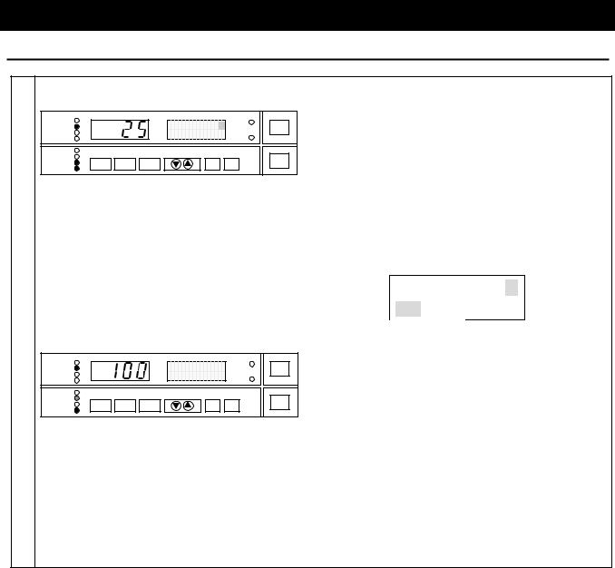
Auto Stop Operation
3 |
Set |
temperature, |
operation |
period/stop |
The |
setting |
temperature |
input |
screen |
|
is |
||||||||
|
time, and fan |
|
|
|
|
displayed. |
|
The |
Sub |
Display |
indicates |
"Set |
|||||||
|
|
|
|
|
|
Set TEMP |
0 |
|
TEMP" and the numeric character that indicates |
||||||||||
|
AUTO STOP |
|
|
|
SUBMENU |
temperature blinks. |
|
|
|
|
|
|
|||||||
|
FIXED TEMP |
|
|
|
|
|
DOOR |
|
|
|
|
|
|
|
|
|
|
|
|
|
AUTO START |
|
|
|
Auto-stop OPR |
TROUBLE |
Set the temperature using the "▲▼". |
|
|
|
|||||||||
|
PROGRAM |
|
|
|
|
|
|||||||||||||
|
|
|
|
|
|
|
|
|
|||||||||||
|
STANDBY |
|
|
|
|
|
|
|
|
|
|||||||||
|
|
|
|
|
|
|
|
|
|
|
|
|
|
|
|
|
|
||
|
|
END |
|
|
|
|
|
POWER |
Press the ENTER key to decide the temperature. |
||||||||||
|
|
FAN |
|
|
|
|
|
||||||||||||
|
HEATER |
FUNCTION |
PROGRAM |
MENU |
|
ENTER |
CANCEL |
|
|
|
|
|
|
|
|
|
|
|
|
|
|
|
|
|
|
|
|
|
|
|
|
|
|
|
|||||
|
|
|
|
|
|
|
|
|
The operation period/stop time input screen |
is |
|||||||||
|
FIXED TEMP |
|
|
|
Set TEMP |
100 |
DOOR |
displayed |
after |
the |
setting |
temperature |
is |
||||||
|
AUTO STOP |
|
|
|
SUBMENU |
decided. |
|
|
|
|
|
|
|
|
|
||||
|
PROGRAM |
|
|
Auto-stop OPR |
TROUBLE |
|
|
|
|
|
|
|
|
|
|||||
|
AUTO START |
|
|
|
|
|
|
|
|
|
|
|
|
|
|
|
|
|
|
|
STANDBY |
|
|
|
|
|
|
Display the period/time using the "▲▼". |
|
|
|||||||||
|
|
END |
|
|
|
|
|
POWER |
Input |
the |
operation period when the setting of |
||||||||
|
|
FAN |
|
|
|
|
|
||||||||||||
|
HEATER |
FUNCTION |
PROGRAM |
MENU |
|
ENTER |
CANCEL |
|
|
|
|
|
|
|
|
|
|
|
|
|
|
|
|
|
|
|
|
|
|
|
|
|
|
|
|||||
|
|
|
|
|
|
|
|
|
timer mode shows "Time". Input the operation |
||||||||||
|
|
|
|
|
|
|
|
|
stop time when it shows "Clock". |
|
|
|
|
||||||
|
|
|
|
|
|
|
|
|
OPR time |
|
30min |
Stop time |
13:00 |
|
|||||
|
|
|
|
|
|
|
|
|
Auto-stop OPR |
|
|
Auto-stop OPR |
|
|
|||||
|
|
|
|
|
|
|
|
|
(Operation period |
|
|
(Operation stop time |
|
|
|||||
|
|
|
|
|
|
|
|
|
|
edition screen) |
|
|
edition screen) |
|
|
||||
|
|
|
|
|
|
|
|
|
• The display style of operation period varies |
||||||||||
|
|
|
|
|
|
|
|
|
depending on the range of time to be displayed. |
|
|||||||||
Time Range |
Indication |
|
0minute to 59minutes |
0min to 59min |
|
|
|
|
1hour to |
1h00m to 99h59m |
|
99hours59minutes |
||
|
• The input range of operation stop time is always from 0:00 to 23:59.
Press the ENTER key to decide the period/time.
The screen returns to the fan function input screen after the period/time is decided. Select "On" or "Off" using the "▲▼".
Fan |
ON |
Auto-stop OPR
(Fan function selection screen)
18
Operation Method
Auto Stop Operation
4 |
Start operation |
|
|
|
|
||
|
FIXED TEMP |
|
|
|
Set TEMP |
100 ↑ |
DOOR |
|
AUTO STOP |
|
|
|
SUBMENU |
||
|
AUTO START |
|
|
Stop in |
30min |
TROUBLE |
|
|
PROGRAM |
|
|
||||
|
STANDBY |
|
|
|
|
|
|
|
END |
|
|
|
|
|
POWER |
|
HEATER |
FUNCTION |
PROGRAM |
MENU |
|
ENTER |
|
|
|
CANCEL |
|||||
|
FAN |
|
|||||
|
|
|
|
|
|
|
|
|
FIXED TEMP |
|
|
|
Stop time |
DOOR |
|
|
AUTO STOP |
|
|
|
SUBMENU |
||
|
AUTO START |
|
|
2002/01/01 |
12:30 |
TROUBLE |
|
|
PROGRAM |
|
|
||||
|
|
|
|
|
|
||
|
|
|
|
|
|
|
|
|
STANDBY |
|
|
|
|
|
|
|
END |
|
|
|
|
|
POWER |
|
HEATER |
FUNCTION |
PROGRAM |
MENU |
|
ENTER |
|
|
|
CANCEL |
|||||
|
FAN |
|
|||||
|
|
|
|
|
|
|
|
Press the ENTER key to decide the setting and the auto stop operation starts. The blinking AUTO STOP lamp lights on and the Sub Display displays the setting temperature and residual time to operation stop.
The countdown of timer is suspended when the temperature in furnace is 3 or more lower than the setting temperature, or 6 or more higher
than it. In this case, the Sub Display displays "Wait" with blinking. The time display on the right side of "Wait" shows the total waiting time in operation.
Set TEMP 100 ↑
Wait 1min
(Waiting screen)
The operation stops when the residual time counts zero. The END lamp blinks and the Sub Display displays the operation finish time when the operation stops.
The wait function is not activated when the auto stop operation is carried out with "Clock" mode. The operation stops at specified time.
The fan stops at the same time the operation finishes when "OFF" is selected at fan function.
The setting of fan function ["ON"/"OFF"] takes priority, regardless of setting for fan operation in the standby state.
Press the POWER key to quit operation.
19
 Loading...