

Page 1

ROTARY EVAPORATOR
RE440
RE540
(100V)
First Edition
●
Thank you for your Yamato Scientific RE series Rotary Evaporator purchase
●
For best test data, we recommend you purchase our BM series Water Bath.
Please call Yamato Scientific for more details.
Read and apprehend the important warnings in
this instruction manual prior to use.
Page 2

Table of Contents
1. Specifications ....................................................................................................................................1
2. Safety Information ..........................................................................................................................1-5
Safety Symbols………………………… ……… ……… ……… ……… ……… …… ….…1
Safety Precautions………………………………………………………………………3-4
Hazardous Material…………………… ……………………………………………… …..5
3. Identification of Parts………………………………………………………………………………………6
4. Installation/Assembly…………………………………………………………………………………..7-15
Assembling parts
Removing the Evaporation Flask and Steam Duct………………………….……….12
Lift…………..…………………………………………………………………………..…13
Vacuum Hose and Water Supply………………………………………………………14
Power Requirements ……………………………… ……… ……… ……… …….…….. 1 5
5. How To Operate…………………………………………………………………………………………….16
6. Troubleshooting Guide...................................................................................................................17
Problem Solving Chart………………………………………………………………….17
7. Wiring Diagram ................................................................................................................................18
8. Lists of Exchange Parts..................................................................................................................21
9. After Sale Service and Warranty....................................................................................................22
Request for Repair…………………………………………………………………….…22
………………………………………………………………..….
7-11
Page 3
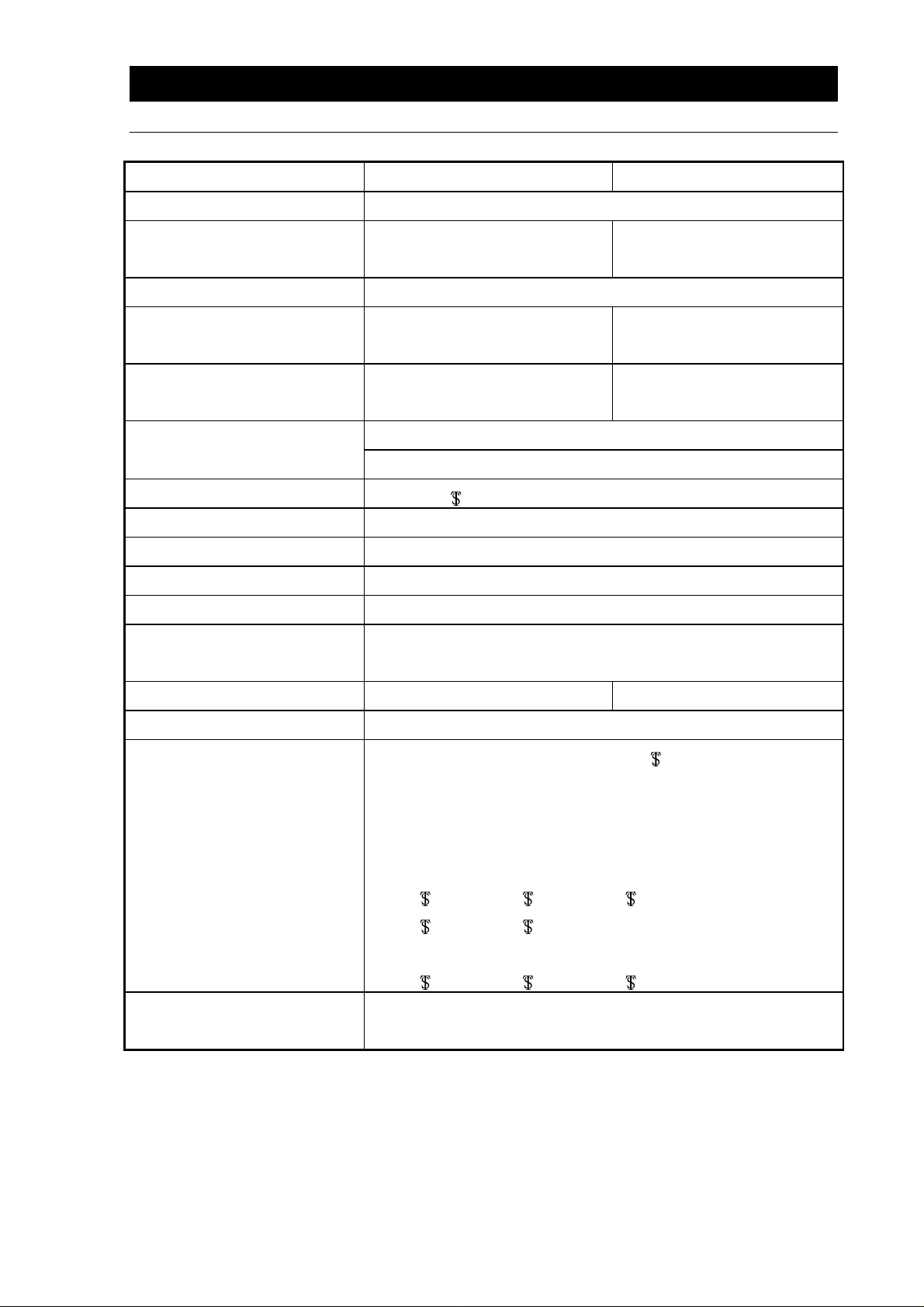
1. Specifications
Type RE440 RE540
Rotation Speed *1
Accuracy of display
‑±
rotation speed *1
Drive system Worm gear system
Rotation speed
‑
display system
Resolution of rotation
‑
speed display
Movable Steam Duct Mechanism, Flask Remover
Other Supplemental System
Power Socket ( for Vacuum Controller )
Glass Joint 29/38 Steam Duct, S35/20 Receiving Flask
Lift Mechanism Electric motor auto lift
Motor(rotation) Induction motor 25W
Glass set Type A, Type B, Type C
Safety device Overcurrent protection ( fuse 2A )
Exterior dimensions
(W×D×H) *2
20‑180rpm
420×340×580 mm
3rpm(at 20‑180rpm)
Digital
1rpm
Weight 13kg 14kg
Power source (RE only)
●
Evaporation Flask (opaque & frosted
2000ml/500ml/300ml/200ml/100ml
●
Receiving Flask ( opaque & frosted S35/20)
2000ml/500ml/300ml
Option
Combination apparatus
*1 The rotation speed indicates performance of the unit equipped with (A, B or C type) glass set in case
of unloaded operation under rated power.
*2 Glass set is not included.
●
Joint (opaque & frosted )
29/42-29/38, 29/42-24/40, 29/42-19/38,
29/42-15/25, 24/40-24/40
●
Trap Ball (opaque & frosted )
29/42-29/38, 29/42-15/25, 24/40-24/40
●
Water Bath BM100/200/400
●
Oil Bath BO600
AC100V±10% 50/60Hz 2 A
29/42)
1
Page 4
2. Safety Information
Safety Symbols
Graphic indications
This instruction manual and our products apply various indications for safety. Ignoring these
indications can caus e such s ituat ions as lis ted be low. Rea d and u nders tand t he fol lowing warn ing an d
caution signs in this manual prior to use.
WARNING
CAUTION
(Note 1) Serious inj ury : Bo dil y harm b y electric sh ock , bone f ractur e or po isonin g whic h m a y require
hospitalization.
(Note 2) Injury : Bodily harm by electric shock, bone fracture or poisoning which may not require
hospitalization.
(Note 3) Damage : Any damage on equipment, facility, structure, etc.
Indicates the possibility of serious or fatal injury (Note 1).
Indicates the possibility of injury (Note 2) or damage (Note 3) to the
equipment.
Meaning of Graphic Indications
Shows warning or caution.
Specific contents are described aside each sign.
Shows users important information not to do.
Specific contents are described aside each sign.
Shows users important information sure to do.
Specific contents are described aside each sign.
1
Page 5
Safety Information
Safety Precautions
If the motor overloads - stop operation immediately.
If you continue operation under abnormal overload conditions, the motor may stop by the safety
device. If the motor stops, turn the volume knob to the minimum and cut the switch off.
Overload means the situatio n when the mo tor surfac e heats up more than 90
****
rust on ball bearing etc.,
due to
℃℃℃℃
Make sure that the volume knob indicates “min” before turning the unit on.
Make sure that the volume knob is at “min”. If the volume knob is not turned to “min”, the
evaporation flask turns round when you turn on the power switch.
Move the lift up or down after you stop rotation of the evaporation flask.
If the lift is moved up or down while the evaporation flask is rotating, scalding may occur due to
dispersing of hot water. Be sure to move the lift after turning the volume knob to the minimum.
Never fail to ground the unit.
This unit uses a 3-core power cord (including ground wir e). Be sure to groun d the unit for safet y.
Be cautious using flammable chemicals.
This unit is not explos ion pr oof . Do no t use in f lamm able or exp losiv e gas en vironm ents and d o
not evaporate explosive substances.
The flask clamp is very springy. Be careful not to break the glass apparatus.
The enclosed flas k clamp is very springy to hold the glas s apparatus firmly. Be careful not to
break the glass.
2
Page 6
Safety Information
Safety Precautions
Only water to be used with the Water Bath.
Only water in the W ater Bath. Probl ems can oc cur if anythi ng other than water is us ed. Also be
sure not to heat with low water level or the bath can overheat.
Use a trap.
Use a trap when you decom press by hydraul ic rotary vacuum pump. W hen you use our Hand y
Aspirator, fill to overflow.
Maintain the vacuum seal.
●
The vacuum seal is expendable. Exchange the seal in case of vacuum-down.
●
You can use the v acuum seal wit hout gre ase. B ut you desir e m ore longer lif e of the seal, put
silicon grease on to t he r ipped side of vac uum seal. If you are af r aid of s ample contaminat ion,
use liquid sample.
Cleaning the exterior of RE series evaporator
Do not use any volatile chem icals to clean the ext erior of th is unit. This could damage the color
and shape. Wipe clean with a soft dry towel , etc.-Do not use a brush.
If the unit is not in use for a long period of time, cut the power supply.
If the unit is not in use for a long period of time, turn the power off and pull out the power cord for
safety.
3
Page 7
Safety Information
Hazardous Material
Do not use the Unit in flammable or explosive gas environments of substances
listed below. Do not evaporate explosive substances.
Nitroglycol, Nitroglycerin, Nitrocellulose, and other explosive nitric
esters.
Trinitrobenzene, Trinitrotoluene, Picric acid, and other explosive nitro
compounds.
Peracetic acid, M ethyl ethyl k etone per oxide, Benzo yl peroxide, and
other organic peroxides.
Sodium azide, and other metallic azides
Metallic lithium, Metallic potassium, Metallic sodium, Yellow
phosphorus, Phosphorus sulfide, Red phosphorus, Celluloid,
Calcium carbide, L ime phosphate, Magnesi um powder, Aluminum
powder, and other c om bustibl e m etal po wders and s odium dithio nite
(hydrosulfite).
Potassium chlorate, Sodium chlorate, Ammonium chlorate, and
other chlorates.
Potassium perchlorate, Sodium perchlorate, Ammonia perchlorate,
and other perchlorates.
Potassium peroxide, Sodium peroxide, Barium peroxide, and other
inorganic peroxides.
Potassium nitrate, Sodium nitrate, Ammonia nitrate, and other
nitrates.
Explosive
Explosive
Substance
Combustible
Substance
Oxidant
Flammable
Ignitable
Substance
Combustible
Gas
Sodium chlorite and other chlorites.
Calcium hypochlorite and other hypochlorites.
Ethyl ether, Gasoline, Acetaldehyde, Propylene Oxide, Carbon
disulfide, and other flammable substances with a flash point belo w
minus 30ºC.
Normal hexane, Ethylene oxide, Acetone, Benzene, Methyl ethyl
ketone, and other flamm able substances with a flash point between
minus 30ºC and 0
Methanol, Ethanol, X ylene, Pentyl acetate (amyl acetate) , and other
flammable substance with a flash point between 0ºC and 30ºC.
Kerosene, Light oil, Tur pentine oil, Isoam yl alco hol, Acet ic acid, a nd
other flammable substances with a flash point between 30ºC and
65ºC
Hydrogen, Acetylen e, Ethylene, Metha ne, Ethane, Pro pane, Butane
and other flammable gas at 15℃ degree and under 1 atmosphere.
o
C.
4
Page 8
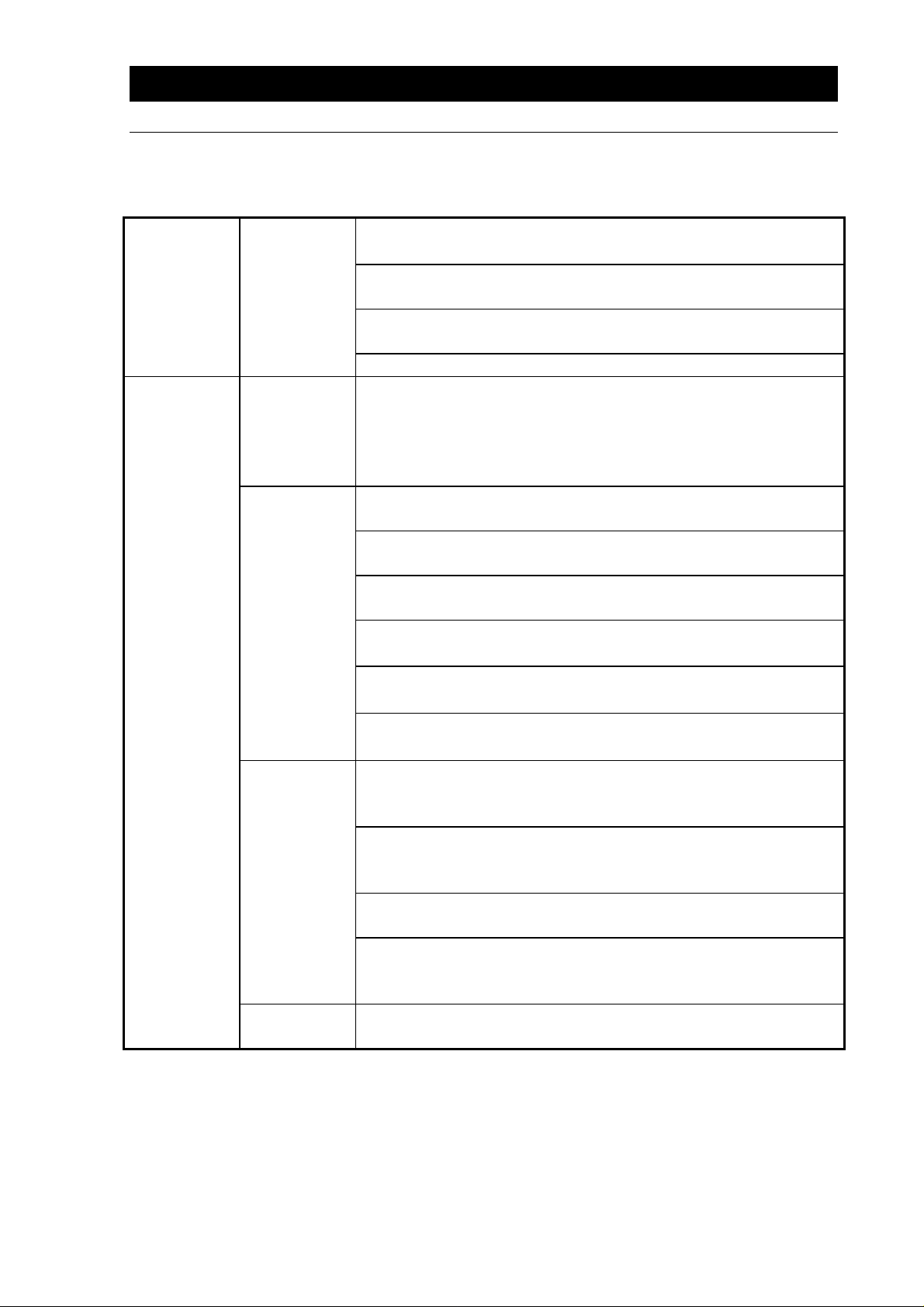
RE440 (type A)
3. Identification of Parts
With Condenser A
Cock
Opening to Pour
Sample
Cooling Tube (type A)
Flask Clamp
Rotary Joint Holder
Stand
Vacuum Pipe
Cooling Water
Pipe
Vacuum Regulator VR100
Control Box
Volume Knob
Motor
Flask Remover
Flask Clamp
Distilling Flask
Water Bath BM400
RE540 (type A)
Tachometer
5
Page 9

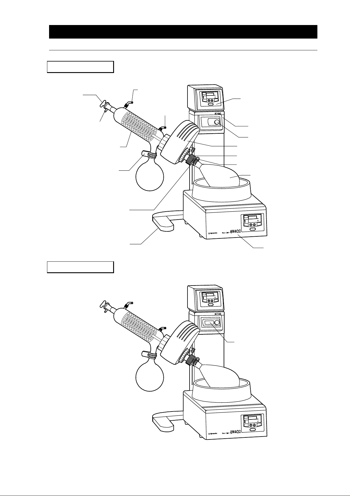
RE440 (type B)
Identification of Parts
With Condenser B
Cooling Tube (type B)
Connecting Tube
Cooling Tube Holder
Cooling Tube Holder Shaft
RE540 (type B)
6
Page 10

RE440 (type C)
Cooling Tube (type C)
Identification of Parts
With Condenser C
Cooling Tube Lid
RE540 (type C)
*
Please understand that our products are subject to some specification changes without notice.
*
The exterior design above are just examples of the interchangeable parts.
7
Page 11

4. Installation/Assembly
1. Set the Body at a stable place.
Be sure to set the body at a stable place.
2. Fix the motor to the body.
1. Insert the motor bearing bar into the motor support clamp of the body, put D cut surf ace (flat
surface) of the bar perpendicularly to either 2 upper pr side screws, and fasten 4 fix screws tightly
by using the attached hexagonal wrench (for M5).
Then, slant the motor to the right (about 45°), and fix the finger screw of the motor tightly.
If you do not fasten the screws tightly, vibration may occur preventing accurate
measurements or the motor may fall causing the glass apparatus to break.
Finger Screw
Motor Support Clamp
2. Remove the cooling condenser nut (the bigger nut with the coil ring) and coil ring when you fix the
motor.
8
Page 12

Installation/Assembly
g
3. Inserting the steam duct into the motor
1.Before you insert the s team duct, m ake s ure the O-r ings ins ide the m otor center h ole are no t out
of place. If so, reset them in the right place.
2.Insert the steam duct from the right side into the center hole of the motor.
3.Set the steam duct to the desired position with a minimum of 5mm between the blue flask
remover and the steam duct holder.
4.Tighten the steam duct holder by turning c lockwise. Be sure to tighten the steam duct holder
firmly so that the steam duct does not slip.
Steam Duct Holder
Flask Remover
Rubber O- Rin
Keep at least 5mm
When removing the steam duct, first loosen the steam duct holder. Do not remove the
※※※※
steam duct holder or the rings may slip out.
If the rings come off in setting / removing the steam duct and you do not know how to
●●●●
assemble…..
See the following picture to re-assemble.
9
Page 13

Installation/Assembly
4. Set the cooling condenser nut, coil ring and vacuum seal to the condenser or
condenser connector.
1. Remove the cooling condenser nut and coil ring on the left side of motor.
2. Connect the cooling condenser nut and then the coil ring to the condenser or condenser
connector (which ever applies). Be sure to put the nut on first.
3.Insert the vacuum seal to the condenser or condenser connector (which ever applies).
※
It is optional to put grease on the vacuum seal.
Cooling Condenser Nut
Coil Ring
●
Insert the convex side of the vacuum
seal into the flange of cooling
condenser or condenser connector.
Vacuum Seal
5. Connect cooling condenser or cooling condenser connector to the motor.
Insert the steam duct into vacuum seal, put glas s flange to the m otor and fasten firm ly the cooling
condenser nut.
Be careful not to damag e the set vacuum seal w hen you put steam duct into the flange
****
with the seal in case the damage could cause leak.
Glass Type A Glass Type B/C
Above :
Below :
Vacuum Seal
Coil Ring
Fitting of Coil Ring and Vacuum Seal
Fitting to Motor
Above :
Below :
Vacuum Seal
Coil Ring
Fitting of Coil Ring and Vacuum Seal
Fitting to Motor
When you remove the coil ring from cooling condenser or condenser connector
●●●●
Hook the coil ring b y the attached hexagon wrench as shown in the left
picture in order t o remove the ring e asily from the cooling c ondenser or
connecting condenser. Howe ver, be careful n ot to force too hard in case
the glass apparatus or the coil ring might be damaged.
10
Page 14

Installation/Assembly
6. Connecting the cooling condenser holder shaft. (glass set B & C only)
Fit the cooling condenser holder shaft firmly into the screw hole on the back of motor. Put the
attached hexagon wrench through the hole on the end of shaft and fasten tightly.
7. Connecting the cooling condenser and condenser holder (B & C
condensers only)
1. Connect the cooling condenser to the condenser connector a nd hold by the cooling condenser
clamp.
2. Insert the cooling condenser holder from the top of condenser, while fitting the other side
through the holder shaf t. (For type C, be sure to inser t the cooing condenser ho lder from the
bottom of condenser rather than top and then connect the condenser to the condenser
connector)
Cooling Condenser Clamp
3. Fit the suction cock for type B or the cooling condenser lid for type C.
Cooling Condenser Holder
Suction Cock
Condenser Lid
11
Page 15

Installation/Assembly
8. Connecting the Evaporation and Receiving Flasks.
Insert the evaporation flask into the steam duct and hold by the flask clamp. In addition, connect the
receiving flask in the same way by the flask clamp to the cooling condenser or condenser
connector.
●
Evaporation Flask
1. Turn the blue flask remover ring upward.
2. Connect the flask to the steam duct, and
hold by the evaporation flask clamp.
Flask Clamp
Connect the flask to the cooling condenser or
the connecting condenser, and hold by the
flask clamp.
●
Receiving Flask
Flask Clamp
9. Insert the feed tube to the cooling condenser or condenser connector.
Assembly is now complete.
Feed Tube
12
Page 16

Installation/Assembly
Removing the Evaporation Flask and Steam Duct
10. Evaporation flask
Remover the flask clamp while holding the evaporation flask, and rem ove the evaporation flask
from the steam duct.
If the evaporation flask does not easily come off, use the blue flask remover.
For easy evaporation flask removal…
●●●●
Turn the flask remover to touch the end of f lask. Rotate further left and you c an push out th e
flask easily without force.
If you tap the flask to remove, the glass apparatus may break.
****
Flask Remover
Flask Clamp
11. Steam duct
When you loosen the steam duct holder, the joint comes off easily.
Loosen the steam duct holder, but do not take it off when you remove the steam duct.
*
If you remove the holder, the rings will come off.
●
In case the rings should com e off, and you do not know ho w to assem ble them, see the chart
for re-assembly( P8 ).
13
Page 17

Installation/Assembly
12. How to operate the lift.
Easily move the lift up or down by using the lift switch located on the right side of the unit.
●
Operate the lift switch as follow;
To lift up
・
Push the upper side of the lift switch,
then the lift goes up.
・
Even if you let your hand off the
switch, the lift stops automatically.
To lift down
・
Push the lower side of the lift switch,
then the lift goes down.
Lift
・
Even if you let your hand off the
switch, the lift stops automatically.
The lift stops automatically at the upper or lower end of stroke.
*
14
Page 18

Installation/Assembly
Vacuum Hose and Water Supply
13. Fit the hose joints to the water supply, drain and vacuum hoses at first, and
connect to the cooling water and vacuum pipes.
1. In case the joints are connected to the condenser, remove them.
2. Insert the hos e j o ints into the wat er s upp ly and drain hoses ( ins ide di ameter, 9mm) , hold by the
attached hose clamps and fix to the cooling pipes of cooling condenser.
In the same way, inser t the hose joint into the vacuum hose (inside d iameter of 6m m),fix to the
vacuum suction pipe (hose clamp is not necessary).
Do not fit the hoses to the hose joints connected to the condenser.
In case of glass A
●
Water Supply and
Drain Hoses
In case of glass C
●
Vacuum Hose
In case of glass B
●
Water Supply and Drain Hoses
Vacuum Hose
Drain Hose(Φ18)
Connect the drain hose with the inside diameter
of 18mm to drain of cooling condenser.
Vacuum Hose
15
Page 19

Installation/Assembly
Power Requirements
14. Connect the power plug into an outlet.
1. Connect the power cord of the body to AC100V power source.
Never fail to conn ect the earth for safety.
Be sure to switch off whenever you insert or pull out the power cord.
****
2. Then, joint the motor connecting cable to the socket on the back of controller.
15. Connect the vacuum controller, in case it is attached.
Prepare additionally an aspirator with displacement of 10
****
●
Combination with the vacuum controller VR100.
You can fix the vacuum controller, as shown in the
right picture, by metal fastener onto the controller
box of RE400/500 Rotary Evaporator.
In addition, you can connect the power cord of
VR100 to the power sock et on the back of Rotary
Evaporator controller.
****
In case of RE200, you can not fix the vacuum
controller on RE200 and c onnect th e po wer cord of
VR100 to RE200, so set and handle on a stable
place near by.
Look at the back panel of vacuum controller where hoses to connect are indicated. Follow the
indications and connect the hoses.
Be sure to read the attached instruction manual to handle the vacuum controller.
****
/min. as a vacuum device.
リットル
リットル
リットルリットル
VR100
RE400 or RE500
16. Prepare bath (separately sold)
Set the bath in front of the body, and pour water into it.
Be sure to read the attached operation manual to handle the bath.
****
BM400/BO600 BM200 BM100
16
Page 20

5. How To Operate
1. Pour cooling water/alcohol into the cooling condenser.
●
In case of glass A or B
Circulate the cooling water in the cooling condenser.
●In case of glass C
Put dry ice and pour alcohol carefully so that it does not overflow.
2. Put sample into the evaporation flask.
Put sample into the evaporation flask.
Pour sample to fill the half of the evaporation flask capacity. Liquid collected in the
****
receiving flask shall be also kept within approximately the half level.
3.Heat the bath.
Set the bath temperature at the required degree and heat up to the set point.
4. Turn the power on, and operate the lift.
1.When the bath temperature reaches the set point, make sure that the volume knob stays at “min”,
and turn on the power switch on the right side of control box.
If, at this time, the volume knob is not at “min”, the evaporation flask rotates when you
****
turn the power on.
2.Operate the lift switch to put the evaporation flask gently into water bath, and determ ine the
adequate operational position.
5. Start rotation
Set the volume knob at the required speed to rotate. Operate the vacuum device as well for
evaporation.
When you supply sample during the unit operating
●●●●
Connect the teflon tub e ( ins ide di ameter 6mm) to the op en ing for sample and h and le t he c oc k to
let certain amount sucked in.
6. Move the lift up or down after you stop rotation of the evaporation flask.
If the lift is moved up from or down into the bath while the evaporation flask is
rotating, scalding may occur due to dispersing of hot water.
7. When the operation ends
When the operation ends and you want to remove the evaporation or receiving flask , open the cock
and bring back pressure inside the container to normal.
8. Operation after restarting from power failure.
The unit restarts the same operation as before after recovering from power failure.
17
Page 21

6. Troubleshooting Guide
Problem Solving Chart
Trouble & Countermeasure
Check the following points if there should or seem to be some machine trouble.
Contact Yamato’s Technical Service Department in case trouble is not solved in spite of
countermeasures below.
Trouble Cause Countermeasure
Digital display does not
light up on the controller.
Lift will not move.
The flask will not rotate
●
Power is off
●
Disconnection of power cord
●
Fuse blows
●
Power is off
●
Disconnection of power cord
●
Fuse blows
Overload (any non-standard
heavier glass set or apparatus
is equipped )
●
Switch of controller is off
●
Volume knob is at the “min”
●
Disconnection of motor cable
●
Incomplete set-up or fastening
of steam duct cause racing
●
Something touches the flask
●
Check power source
●
Connect the cord of motor and
body
●
Exchange of fuse (2A)
●
Turn the power on
●
Connect the cord of body
●
Exchange of fuse (2A)
●
Provide the specifie d glass set or
apparatus
●
Turn on the power switch
●
Turn the volume knob up
●
Insert into the socket on the
controller
●
Fasten the steam duct holder
●
remove something that contacts
Incomplete vacuumization
●
Wear and deterioration of
vacuum seal
●
Direction of vacuum seal is
wrong
●
Cooling condenser nut is
incompletely fastened
●
Glass apparatus break
●
Incomplete connection of glass
apparatus
●
Leak from hose joints
18
●
Exchange of vacuum seal
●
Re-set the vacuum seal
●
Re-fasten
●
Exchange
●
Re-set
●
Put vacuum grease on
●
Check, re-fasten and p ut vacuum
grease on joints
Page 22

RE440
Wiring Diagram
RE440
Ω
10.5k
Symbol Name of Parts Symbol Name of Parts
P1 Power Plug CN1 Drive Socket
S1 Power Socket ( for Vacuum Controller) MC Drive Cable
SW1 Power Switch F1 Fuse (2A)
SPC1 Speed Control Pack LFS Lift Switch
M1 Motor S Rectifier Stack
G Tachogenerator LS1 Highest Limit Switch
C1 Motor Condenser LS2 Lowest Limit Switch
VR1 Resister to Set Rotation Speed M2 Lift Motor
19
Page 23

RE540
Wiring Diagram
RE540
Symbol Name of Parts Symbol Name of Parts
P1 Power Plug MC Drive Cable
S1 Power Socket (for Vacuum Controller) F1 Fuse (2A)
SW1 Power Switch T1 Transformer
SPC1 Speed Control Pack B1 Tachometer Substrate
M1 Motor LFS Lift Switch
G Tachogenerator S Rectifier Stack
C1 Motor Condenser LS1 Highest Limit Switch
VR1 Resister to Set Rotation Speed LS2 Lowest Limit Switch
CN1 Drive Socket M2 Lift Motor
20
Page 24

8. Lists of Exchange Parts
Name of Parts Parts No. Application
Cooling Condenser (A) RG00A-30021 For A type
Cooling Condenser (B) RG00B-30020 For B type
Cooling Condenser (C) RG00C-30021 For C type
Condenser Connector (B) RG00B-30030 Common use for B&C type
Evaporation Flask RG00A-30040 Common use for all types
Receiving Flask RG00A-30050 Common use for all types
Steam Duct RGY0A-30010 Common use for all types
Cock 255191-415 Common use for all types
Suction Cock RG00B-40030 For B type
Cooling Condenser Clamp 7060026002 Common use for B & C type (the life is limited)
Receiving Flask Clamp 7060026004 Common use for all types (the life is limited)
Evaporation Flask Clamp 7060026001 Common use for all types (the life is limited)
Teflon Tube (A) 255191-416 For A type L=540mm
Teflon Tube (B) 255192-417 For B&C type L=350mm
Hose Joint RG00A-30030 Common use for all types
Hose Clamp 4320016004 Common use for all types
Ring (Large) RE500-40093 Common use for all types(the life is limited)
Ring (Middle) RE500-40061 Common use for all types(the life is limited)
Ring (Small) RE500-40073 Common use for all types(the life is limited)
O Ring 4210020011 Used to fix Steam duct (the life is limited)
O Ring 4210020012 Used to fix Flask Remover (the life is limited)
Vacuum Seal RE500-40090 Common use for all types (the life is limited)
Φ
Fuse (for Body) 2100010011
5.2×20 AC125V 2A
21
Page 25

9. After Sale Service and Warranty
Request for Repair
When you request repair
If any troubles should occur, stop the operation immediately, turn the power off, pull the power cord out
and contact Yamato Sciectific’s Technical Service Department.
Necessary information
●
Model Number
●
Serial Number
●
Date of Purchase
●
Distributor Name
●
Information on difficulties
Be sure to show the warranty when service man visits you.
Warranty (Accessory)
●
Keep your warranty card for future references. Check the name of the distributor, date of purchase
and any other contents of warranty.
●
The terms of warranty is one year limited commencing the date of purchase. Repair is made without
charge according to the contents of warranty.
●
As for repair after expiration of the warranty period, consult the seller or our service office. As long as
the function of the unit is maintained by repair, upon your request, we’ll repair it with charge.
Minimum period to keep repair parts in stock
Minimum period to keep repair -parts in stock is 7 years after the production stop. The repair parts
means any necessary parts to maintain the performance of the unit.
22
 Loading...