

Page 1

ROTARY EVAPORATOR
RE400
First Edition
●
Thank you for your Yamato Scientific RE Series Rotary Evaporator purchase.
●
For best test date, we recommend you purchase our BM series Water Bath.
Please call Yamato Scientific for more details.
●
For proper use of this unit, please read the instruction manual and warranty thoroughly before
operation. Keep both for any future references.
Read and apprehend the important warning signs
in this instruction manual prior to use.
Page 2

Contents
SAFETY INFORMATION ........................................................................................................................1
AFETY SYMBOLS
S
AFETY PRECAUTION
S
NOTES TO USERS................................................................................................................................. 4
AME OF EACH PART
N
HOW TO ASSEMBLE............................................................................................................................. 5
EXPLANATION ON HANDLING OF LIFT ............................................................................................10
PREPARATION AND OPERATION METHOD..................................................................................... 11
MAINTENANCE.....................................................................................................................................14
HEN YOU SUSPECT “TROUBLE
W
AFTER-SALE SERVICE AND WARRANTY.........................................................................................15
LISTS OF EXCHANGE PARTS............................................................................................................ 16
SPECIFICATION ................................................................................................................................... 17
WIRING DIAGRAM ...............................................................................................................................18
REFERENCE.........................................................................................................................................19
AZARDOUS MATERIALS
H
..................................................................................................................................1
.............................................................................................................................2
..............................................................................................................................4
?”........................................................................................................ 14
.......................................................................................................................19
Page 3

Safety Information
Safety Symbols
Graphic Indications
This instruction manual and our pr oducts apply various indications for s af ety. Ignoring these indications
can cause such situations as listed below. Read and apprehend the following warning and caution signs
in this manual prior to use.
WARNING
CAUTION
(Note 1) Serious injury: Bodily harm by electric shock, bone fracture or poisoning which may require
hospitalization.
(Note 2) Injury: Bodily harm by electric shock, bone fracture or poisoning which may require
hospitalization.
(Note 3) Damage: Any damage on equipment, facility, structure, etc.
Indicates the possibility of serious or fetal injury. (Note 1)
Indicates the possibility of injury (Note 2) or damage (Note 3) to the
equipment.
Meaning of Graphic Indication
Shows warning or caution.
Specific contents are described aside each sign.
Shows users important information.
Specific contents are described aside each sign.
Shows users important information.
Specific contents are described aside each sign.
1
Page 4

Safety Information
If the motor overloads-stop operation immediately
If you continue operation under abnormal overload conditions, the motor may stop. If the motor
stops, turn the volume knob to the minimum and cut the switch off, suspending operation for a
while.
Safety Precaution
****
Overload means the situation when the mo tor surface heat s up more than 90
rust on ball bearing etc.,
℃℃℃℃
due to
Never fail to ground the unit.
This unit uses 3-core power code (including ground wire). Be sure to ground the unit for safety.
Be cautious using flammable chemicals
Since this unit is not of explosion proof, do not use in flammable or explosive environments.
The flask clamp contains a strong spring. Be careful not to break the glass
apparatus
The enclosed flask clam p contains a strong spr ing to hold the glass apparatus firm ly. Be careful
not to break the glass.
Use a trap.
Use a trap when you decompress by hydraulic rotary vacuum pump. W hen you use our Handy
Aspirator, fill to overflow.
Maintain the vacuum seal.
●
If the vacuum seal dries, friction occurs between the rotary joint, creating a strange noise.
(This can cause problems.)
●
The vacuum seal is expendable. Exchange the seal in case of vacuum-down.
●
Put silicon grease onto the ripped side of vacuum seal so that it might not dry. If you are afraid
of sample contamination, use liquid sample. However, you can’t use organic sample.
2
Page 5

Safety Information
Safety Precautions
Cleaning the exterior of the RE series evaporator
Do not use any volatile chemicals to clean the exterior of this unit. This could damage the c olor
and shape. Wipe clean with a soft dry towel, etc.-Do not use a brush.
If the unit is not in use for a long period of time, cut the power supply.
If the unit is not in use for a long period of time, turn the power off and pull out the power cord for
safety.
3
Page 6
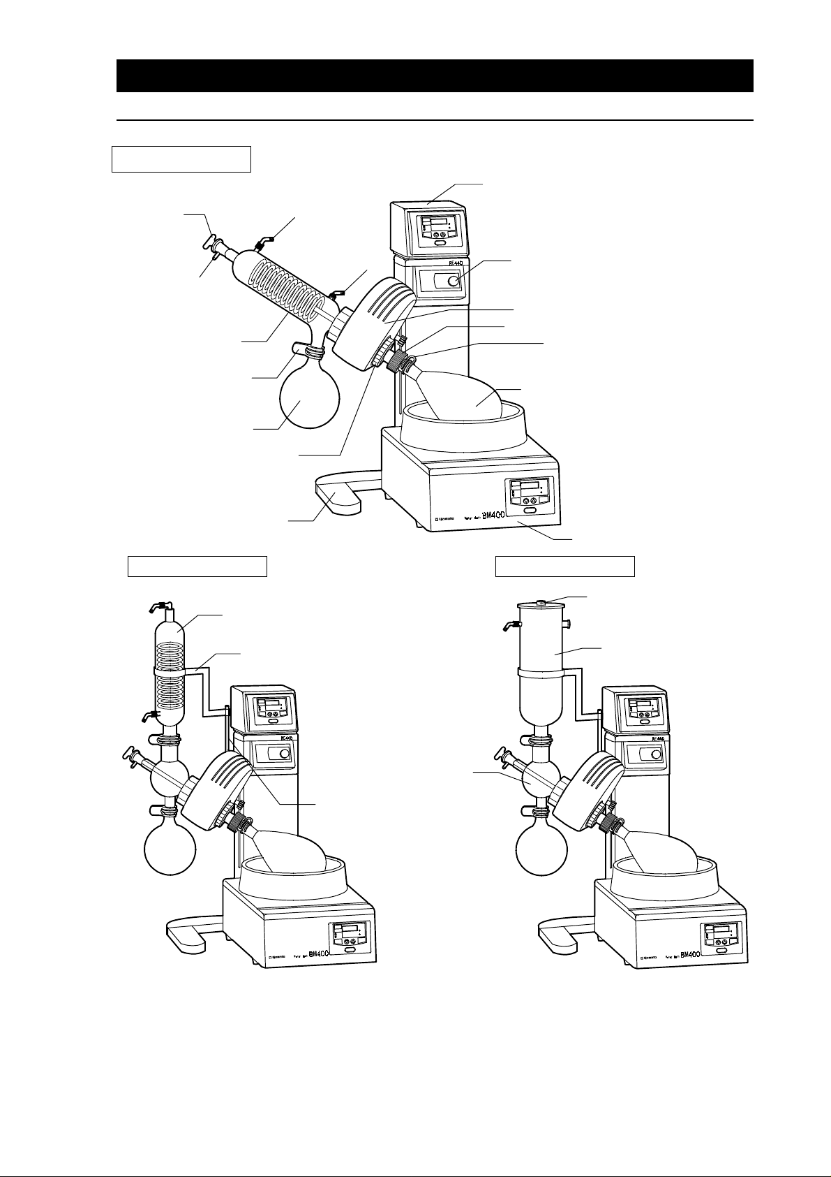
RE400 (type A)
Notes to Users
Name of each part
Control Box
Cock
Opening to Pour
Sample
Cooling Tube (type A)
Flask Clamp
Receiver Flask
Steam Duct Holder
Stand
Vacuum Pipe
Cooling Water
Pipe
Volume Knob
Motor
Flask Remover
Flask Clamp
Distilling Flask
RE400 (type B) RE400 (type C)
Cooling Tube (type B)
Water Bath BM400
Lid
Cooling Tube Holder
Connecting Tube
Cooling Tube Holder Shaft
●
Please understand that our products are subject to some specification changes without notice.
●
The exterior designs above are just examples of the interchangeable parts.
Cooling Tube (type C)
4
Page 7

How to Assemble
1. Unpack the package and take out the components.
Unpack the package and set the stand of the body on the stable place. If you don’t set the unit on the
stable place, vibration or noise occurs, or the unit could fall and get damages.
2. Fix the motor to the body.
1. Insert the motor bearing bar into the metal support of the body, put D cut surface ( f lat sur f ac e) of
the bar perpendicularly to either 2 upper pr side screws, and fasten 4 fix screws tightly by using
the attached hexagonal wrench (for M5).
Then, slant the motor slightly to the right (about 45°), and fix the finger screw of the motor.
****
If you fasten loose, vibratio n occurs and prev ents accurate measurement , or the motor
comes off and the glass apparatus could break.
Finger Screw
2. Remove the cooling tube fastening k not (the bigger knot with a inner spring) when you fix the
motor.
5
Page 8

How to Assemble
3. Insert the rotary joint into the motor.
Push the rotary joint from the right side into the motor sleeve while turning the (blue) flask rem over
downward, and fix firmly the rotary joint holder. Keep m ore than 5mm between the flask rem over
and the rotary joint holder. Fasten so tightly that the rotary joint wouldn’t slip even if you pull with full
strength by your single hand. If you fasten loose, the rotary joint might come off during operation, or
be sucked in during vacuumization.
****
When you remove the rotary joint, don’t take off but loosen the rotary joint holder. If you
remove the holder, the inside parts would come off.
Rotary Joint Holder
Flask Remover
Keep at least 5mm
●
If rubber parts come off in setting/removing the rotary joint, and you don’t know how to
assemble...
See the following picture to re-assemble when the internal parts com e of f in setting or removing the
rotary joint.
6
Page 9

How to Assemble
4. Fit 3 parts, the cooling tube nut, coil ring and vacuum seal to flange of
cooling tube or connecting pipe.
Fit the vacuum seal, cooling tube nut, and coil ring to the f lange of either cooling pipe (A set) or
connecting pipe (B or C set).
****
I f you put the coil ring first, others wouldn’t fit in. In addition, if you put forcibly, glass
apparatus could flaw or break.
****
To reduce friction and produce more effective vacuum, put vacuum grease on the vacuum
seal (accessory).
5. Fit the glass flange to the motor.
Insert the rotary joint into vacuum seal, put glass flange to the motor and fas ten firmly the cooling
tube nut.
****
Be careful not to damage the set v acuum seal when you put rotary joint into the f lange
with the seal in case the damage could cause leak.
****
In order to reduce friction and produce better vacuum, put vacuum grease (accessory)
thinly on the vacuum seal.
Vacuum Seal
Coil Ring
Glass Type A Above : Fitting of Coil Ring and Vacuum
Seal Below : Fitting to Motor
●●●●
When you remove the coil ring from cooling tube or connecting tube...
Glass Type Above : Fitting of Coil Ring and Vacuum Seal
B/C Below : Fitting to Motor
Vacuum Seal
Coil Ring
Hook the coil ring by the attached hexagon wrench as shown in the left
picture in order to remove the ring easily from the cooling tube or
connecting tube. However, be careful not to force too hard in case the
glass apparatus might be damaged.
7
Page 10

How to Assemble
6. Fit the cooling tube holder shaft (glass type B and C only)
Fit the cooling tube holder shaft firmly into the screw hole on the back of motor. Put the attached
hexagon wrench through the hole on the end, and fasten tight.
7. Fit the cooling tube holder and joint the cooling tube with the connecting
pipe.
Joint the cooling tube to the connecting pipe, and hold by cooling tube clamp. Then, pass the cooling
tube holder from top of the cooling tube, while fitting the other side hole to the holder shaft. Level and
fix the positions by attached butterfly nut. (In case of C type, pass the cooling tube holder from
bottom over the cooling tube and joint it to the connecting pipe.)
****
Wipe the flanges well before you joint the cooling tube to connecting pipe.
Cooling Tube Clamp
Put the suction cock for B type or the cooling tube lid for C type.
Suction Cock
Holder
Lid
8
Page 11

8. Fit both distilling flask and receiver flask.
How to Assemble
●●●●
Distilling Flask
Connect the flask to the rotary joint, and hold
by the distilling flask clamp.
●
How to use the (blue) flask remover
Use the flask remover if the distilling flask wouldn’t comes off easily from the rotary joint.
Put the flask remover to the end of flask and turn left. You can push out the flask easily without
giving too much force.
****
If you pat the flask to remove, the glass apparatus could break. Use the flask remover
in case the flask wouldn’t comes off.
Joint the flask to the cooling tube or the
connecting pipe, and hold by the flask clamp.
●●●●
Receiver Flask
Flask Remover
9. Fit the cock with teflon tube to the cooling tube or connecting pipe.
Then you had completed the assembly.
9
Page 12

Explanation on Handling of Lift
Hand lift (Supplemental function of RE400)
Adjust by the knobs (big and small) on the right of the body.
1. Loosen the lowest position knob.→Picture 1
2. Turn the lift knob to “Release”, you can freely move the lift up and down. After you determine the
position, return the handle to the original position and you can fix the height.→Picture 2,3
3. After you determine the lowest position, fasten the lowest position knob.→Picture 4,5
The lift wouldn’t go lower than the fixed position. However, this func tion effectively works only
when the lowest position knob is positioned within 135mm from the setting level.
(Picture 1) (Picture 2) (Picture 3)
(Picture 4) (Picture 5)
10
Page 13

Preparation and Operation Method
1. Fit water supply hose, drain hose and a vacuum hose at first to the hose
joints, and insert into the glass screw couplings. (See picture below)
Connect both water supply and drain hoses (inside diameter, 6mm) into cooling water hose joints of
the cooling tube, hold by the attached hose clamp and fit to the cooling tube screw couplings.
In addition, connect the vacuum hose with the inside diameter of 6mm (hose clamp is not
necessary) to the vacuum hose joint and fix to the vacuum suction pipe of cooling tube.
●●●●
In case of glass A
●●●●
In case of glass C
Connect the rain hose with the inside diameter
of 18mm to drain of cooling tube.
●●●●
In case of glass B
11
Page 14

Preparation and Operation Method
2. Connect the vacuum controller, in case it is attached.
****
Prepare additionally an aspirator with displacement of 10 liter/min. as a vacuum device.
●
Combination with the vacuum controller VR100.
You can fix the vacuum controller, as shown in the
right picture, by metal fastener onto the controller
box of RE400Rotary Evaporator.
In addition, you can connect the power code of
vacuum controller VR100 to the power socket on
the back of Rotary Evaporator controller.
Look at the back panel of vacuum controller where hoses to connect are indicated. Follow the
indications and connect the hoses.
****
Be sure to read the attached operation manual to handle the vacuum adjuster.
RE400
VR100
3. Connect the power plug into an outlet.
1. Connect the power code of the body to AC100V power source.
Never fail to connect the earth for safety.
****
Be sure to switch off whenever you insert or pull out the power code.
2. Then, joint the motor connecting cable to the socket on the back of controller.
4. Prepare bath (separately sold)
Set the bath in front of the body, and pour water into it.
****
Be sure to read the attached operation manual to handle the bath.
BM400 BM200
12
Page 15

Preparation and Operation Method
5. Pour cooling water/alcohol into the cooling tube..
●
In case of Glass A or B
Circulate the cooling water in the connected cooling tube.
●
In case of Glass C
Uncover the cooling tube lid, put dry ice and pour alcohol carefully so that it wouldn’t overflow.
6. Put sample into the distilling flask.
After you put sample into the distilling f las k, sink the flask quietly into the bath which contains water
by the hand lift, and determine the level.
****
Pour sample to the half of the distilling flask capacity. Liquid collected in the receiver flask
shall be also kept within approximately the half capacity.
7. Heat the bath.
Set the bath temperature at the required degree and heat up to the set point.
8. Turn on the power switch and start operation.
When the bath temperature reaches the set point, turn on the switch on the right side of control box,
and handle the volume knob to rotate at a certain frequency. Operate the vacuum device for
distillation.
****
When the operation ends and you want to finish the work, open the cock and bring back
pressure inside the container to normal. To take out the distilling flask from the water
bath, turn the volume knob to “min”, and be sure to turn the switch “OFF”. Never fail to
take away sample inside the distilling flask after the operation ends.
●
When you supply sample during the operation...
In order to supply sample into the distilling flask, connect the teflon tube (inside diameter, 6mm) to
the sample injection pipe and handle the cock to let a certain amount sucked in.
13
Page 16

Maintenance
When you suspect “Trouble?”
Trouble & Countermeasure
Check the following points if there should or seem to be some machine trouble.
Trouble Cause Countermeasure
●
Volume is at the “min”
●
Disconnection of motor cable
The flask wouldn’t rotate
Incomplete vacuumization
****
if you have any question, contact the seller or Yamato Scientific office.
●
Incomplete set-up or fastening
of rotary joint cause racing
●
Something touches the flask
●
Wear and deterioration of
vacuum seal
●
Cooler nut is incompletely
fastened
●
Glass apparatus break
●
Incomplete connection of glass
apparatus
●
Leak from pipe joint
●
Turn the volume knob up
●
Insert into the socket on the
controller
●
Fasten the rotary joint holder and
re-set
●
remove something that contacts
●
Exchange of vacuum seal
●
Re-fasten
●
Exchange
●
Put vacuum grease on
●
Stop the leak
14
Page 17

After-Sale Service and Warranty
When you request repair
When you request repair
If any troubles should occur, turn off the power switch, pull out the power supply plug (cable) and contact
the seller or Yamato Scientific office.
Necessary information
●
Type of the unit
●
Production No.
●
Date of purchase
●
Detailed information on troubles
Be sure to show the warranty when service man visits you.
See the warranty or nameplate on the unit
Warranty (Accessory)
●
The seller or Yamato Scientific office give you a warranty. Check the name of seller, date of your
purchase and other contents on the warranty, and keep it carefully.
●
The term of warranty is one year commencing on the date of your purchase. Repair is made without
charge according to the contents of warranty.
●
As for repair after expiration of the warranty period, consult the seller or our service office. As long as
the function of the unit is maintained by repair, upon your request, we’ll repair it with charge.
Minimum period to keep repair parts in stock
Minimum period to keep repair -parts in stock is 7 years after the production stop. The repair parts
means any necessary parts to maintain the performance of the unit.
15
Page 18

Lists of Exchange Parts
Name of Parts Parts No. Application
Cooling Tube (A) RG00A-30021 For A type
Cooling Tube (B) RG00B-30020 For B type
Cooling Tube (C) RG00C-30021 For C type
Connecting Pipe (B) RG00B-30030 Common use for B and C type
Distilling Flask RG00A-30040 Common use for all types
Receiver Flask RG00A-30050 Common use for all types
Rotary Joint RG00A-30011 Common use for all types
Cock 255191-415 Common use for all types
Suction Cock RG00B-40030 For B type
Cooling Tube Clamp 7060026002 Common use for B and C type (the life is limited)
Receiver Flask Clamp 7060026004 Common use for all types (the life is limited)
Distilling Flask Clamp 7060026001 Common use for all types (the life is limited)
Teflon Tube (A) 255191-416 For A type 1=540mm
Teflon Tube (B) 255192-417 For B and C type 1=350mm
Hose Joint RG00A-30030 Common use for all types
Hose Clamp 4320016004 Common use for all types
Ring (Large) RE500-40093 Common use for all types (the life is limited)
Ring (Middle) RE500-40061 Common use for all types (the life is limited)
Ring (Small) RE500-40073 Common use for all types (the life is limited)
O Ring 4210020011 Used to fix Rotary Joint (the life is limited)
O Ring 4210020012 Used to fix Flask Remover (the life is limited)
Vacuum Seal RE500-40090 Common use for all types (the life is limited)
Φ
Fuse (for Body) 2100010011
5.2×20 AC125V 2A
16
Page 19

Type RE400
Specification
Rotational frequency
control range *1
Drive system Worm gear system
Other supplemental system
Lift system Hand lift
Motor Induction motor 25W
Glass set Type A, Type B, Type C
Safety device Overcurrent protection (fuse)
Exterior dimensions
Power source (including Bath)*3
Option
(W×D×H)
*2
20‑180rpm
Movable rotary joint/Distilling flask removal system
Power source for vacuum regulator
420×340×580
AC100V±10% 12A
●
Distilling Flask (2000ml/500ml/300ml/200ml/100ml : opaque &
frosted
●
Receiver Flask (200ml/500ml/300ml : opaque & frosted S35/20)
●
Joint (opaque & frosted :
19/38,
29/42)
29/42-29/38, 29/42-24/40, 29/42-
29/42-15/25, 24/40-24/40)
●
Trap Ball (opaque & frosted :
15/25,
●
Water Bath BM100/200/400
Combination apparatus
*1 The rotary frequency control range indicates per form ance of the unit equipped with (A, B or C type)
glass set in case of unloaded operation under rated power.
*2 Glass set is not included.
*3 12A when Yamato’s Water Bath BM200 or BO600 is connected.
●
Oil Bath BO600
●
Vacuum Controller VR100
24/40-24/40)
29/42-29/38, 29/42-
17
Page 20

RE400
Wiring Diagram
Symbol Name of Parts
P1 Power Plug
S1 Power Socket
SW1 Power Switch
SPC1 Speed Control Pack
M1 Motor
G Speed Generator
C1 Motor Condenser
VR1 Volume Knob to Set Rotation Frequency
CN1 Drive Socket
MC Drive Cable
F1 Fuse
18
Page 21

Explosive
Explosive
Substance
Combustible
Substance
Oxidant
Reference
Hazardous materials
Nitroglycol, Nitroglycerin, Nitrocellulose, and other explosive nitric
esters.
Trinitrobenzene, Trinitrotoluene, Picric ac id, and other explosive nitro
compounds.
Peracetic acid, Methyl ethyl ketone peroxide, Benzoyl peroxide, and
other organic peroxides.
Metallic lithium, Metallic potassium, Metallic sodium, Yellow
phosphorus, Phosphorus sulfide, Red phosphorus, Celluloid, Calcium
carbide, Lime phosphate, Magnesium powder, Aluminum powder,
and other combustible metal powders and sodium dithionite
(hydrosulfite).
Potassium chlorate, Sodium chlorate, Ammonium chlorate, and
other chlorates.
Potassium perchlorate, Sodium perchlorate, Ammonia perchlorate,
and other perchlorates.
Potassium peroxide, Sodium peroxide, Barium peroxide, and other
inorganic peroxides.
Potassium nitrate, Sodium nitrate, Ammonia nitrate, and other
nitrates.
Flammable
Ignitable
Substance
Combustible
Gas
Sodium chlorite and other chlorites.
Calcium hypochlorite and other hypochlorites.
Ethyl ether, Gasoline, Acetaldehyde, Propylene chloride, Carbon
disulfide, and other flammable substances with a flash point below
minus 30ºC.
Normal hexane, Ethylene oxide, Acetone, Benzene, Methyl ethyl
ketone, and other flamm able substances with a flash point between
minus 30ºC and 0
Methanol, Ethanol, Xylene, Pentyl acetate (amyl acetate), and other
inflammable substance with a flash point between 0ºC and 30ºC.
Kerosene, Light oil, Turpentine oil, Isoam yl alcohol, Acetic acid, and
other flammable substances with a flash point between 30ºC and
65ºC
Hydrogen, Acetylene, Ethylene, Methane, Ethane, Propane, Butane
and other flammable gas at 15℃ degree and under 1 atmosphere.
o
C.
19
 Loading...