

Low Temperature Incubator
Model
IJ 100
Instruction Manual
- First Edition -
Thank you for purchasing " Low Temperature
Incubator, IJ100 " of Yamato Scientific Co.,
Ltd.
To use this unit properly, read this "Instruction
Manual" thoroughly before using this unit.
Keep this instruction manual around this unit
for referring at anytime.
WARNING!:
Carefully read and thoroughly understand the
important warning items described in this
manual before using this unit.
Yamato Scientific Co. LTD.

Contents
Cautions in Using with Safety...............................................................1
•
Explanation..................................................................................................................1
•
Table of Illustrated Symbols.........................................................................................2
Fundamental Matters of “WARNING!” and “CAUTION!”...............................................3
•
Before Using this unit............................................................................4
•
Requirements for Installation........................................................................................4
Change the Direction of Opening/Closing Door............................................................7
•
Description and Function of Each Part.................................................8
•
Main Unit......................................................................................................................8
•
Control Panel...............................................................................................................9
Operation Method.................................................................................10
•
Sequence of Operation..............................................................................................10
Independent overheating prevention device...............................................................12
•
Handling Precautions ..........................................................................13
Maintenance Method............................................................................16
•
Daily Inspection and Maintenance .............................................................................16
Setting Air Jacket (Optional accesso ry).............................................17
Long storage and disposal..................................................................18
•
When not using this unit for long term / When disposing............................................18
In the Event of Failure…......................................................................19
•
Safety Device and Error Code....................................................................................19
Trouble Shooting........................................................................................................19
•
After Service and Warranty..................................................................20
Specification.........................................................................................21
Wiring Diagram.....................................................................................22
Replacement Parts Table.....................................................................23
Reference..............................................................................................24
•
List of Dangerous Substances ...................................................................................24
Explanation
Illustrated Symbols
Various symbols are used in this safety manual in order to use the unit without
danger of injury and damage of the unit. A list of problems caused by ignoring
the warnings and improper handling is divided as shown below.Be sure that you
understand the warnings and cautions in this manual before operating the unit.
Cautions in Using with Safety
MEANING OF ILLUSTRATED SYMBOLS
WARNING!
CAUTION!
If the warning is ignored, there is the danger of a problem that
may cause a serious accident or even fatality.
If the caution is ignored, there is the danger of a problem that may
cause injury/damage to property or the unit itself.
Meaning of Symbols
This symbol indicates items that urge the warning (including the caution).
A detailed warning message is shown adjacent to the symbol.
This symbol indicates items that are strictly prohibited.
A detailed message is shown adjacent to the symbol with specific actions not to
perform.
This symbol indicates items that should be always performed.
A detailed message with instructions is shown adjacent to the symbol.
1
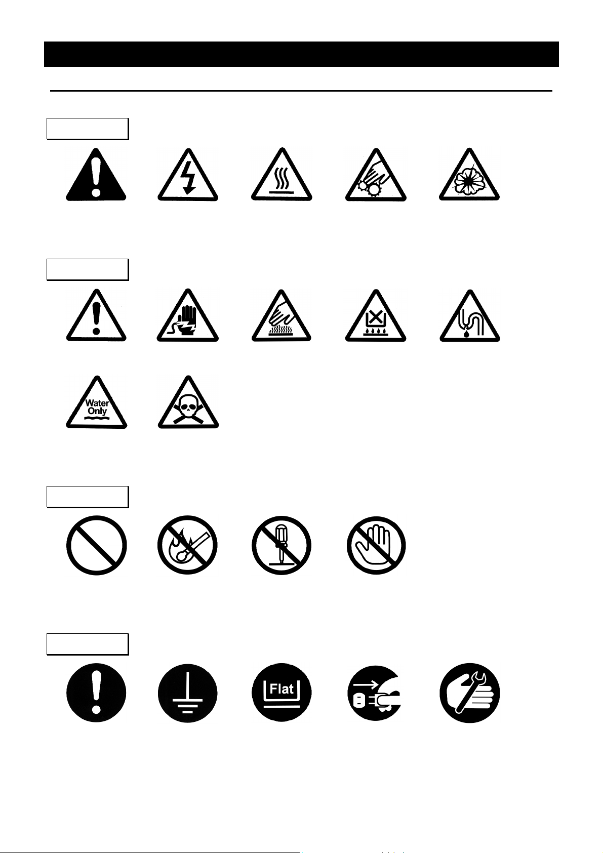
Table of Illustrated Symbols
Warning
Cautions in Using with Safety
Warning,
generally
Caution
Caution,
generally
Caution,
water only
Warning,
high voltage
Caution,
electrical shock
Caution,
deadly poison
Warning,
high temperature
Caution,
scald
Warning,
drive train
Caution,
no road heating
Warning,
explosive
Caution,
not to drench
Prohibit
Prohibit,
generally
Compulsion
Compulsion,
generally
inflammable
Compulsion,
connect to the
Prohibit,
grounding
terminal
to disassemble
Compulsion,
install on a flat
Prohibit,
surface
Prohibit,
to touch
Compulsion,
disconnect the
power plug
Compulsion,
periodical
inspection
2
Cautions in Using with Safety
Fundamental Matters of “WARNING!” and “CAUTION!”
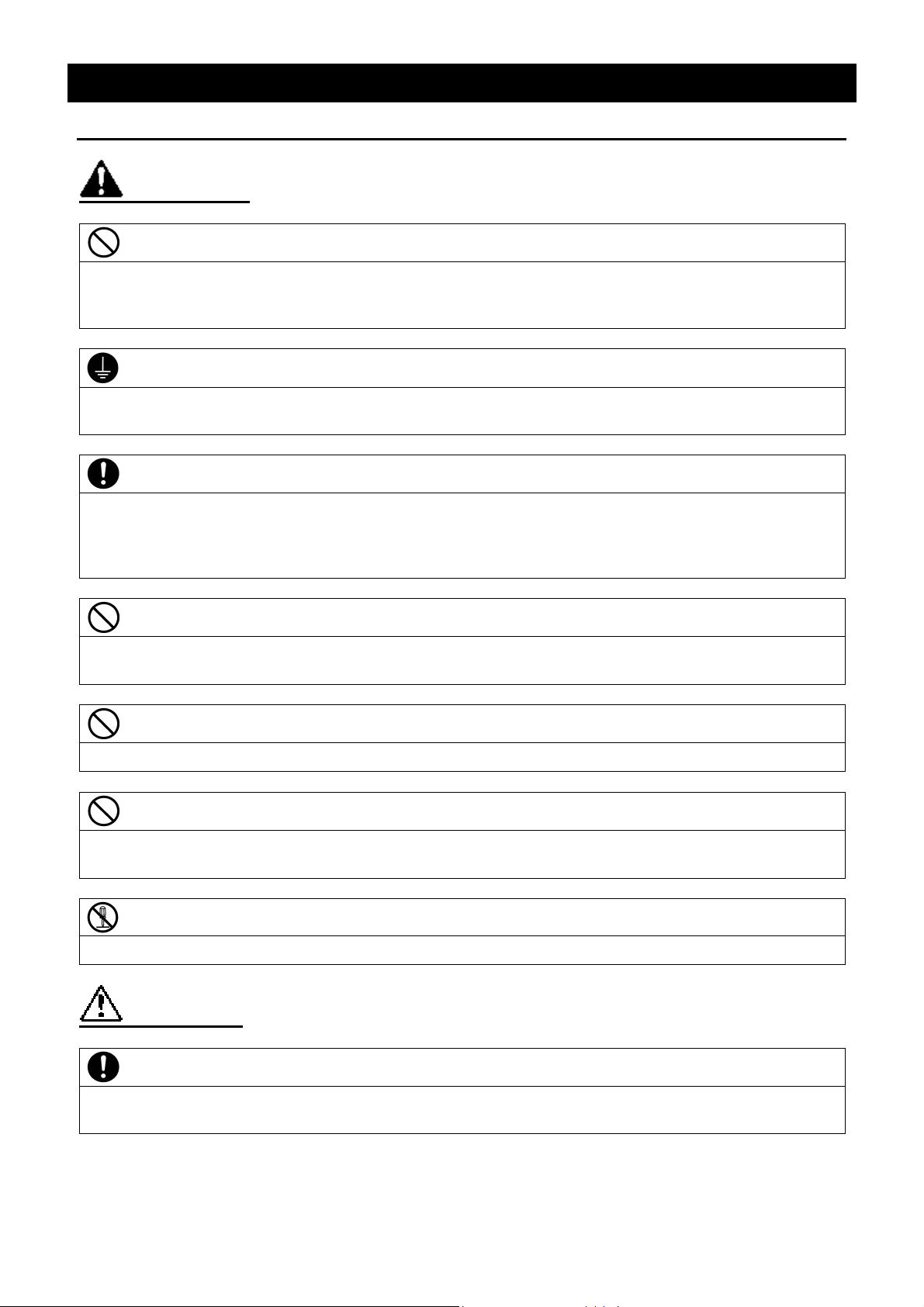
WARNING!
Do not use this unit in an area where there is flammable or explosive gas
Never use this unit in an area where there is flammable or explosive gas.
This unit is not explosion-proof. An arc may be generated when the power switch is turned on or off,
and fire/explosion may result. (Refer to page24 “List of Dangerous Substances”.)
Always ground this unit
Always ground this unit on the power equipment side in order to avoid electrical shock due to a power
surge.
If a problem occurs
If smoke or strange odor should come out of this unit for some reason, turn off the power key right
away, and then turn off the circuit breaker and the main power. Immediately contact a service
technician for inspection. If this procedure is not followed, fire or electrical shock may result. Never
perform repair work yourself, since it is dangerous and not recommended.
Do not use the power cord if it is bundled or tangled
Do not use the power cord if it is bundled or tangled. If it is used in this manner, it can overheat and
fire may be caused.
Do not process, bend, wring, or stretch the power cord forcibly
Do not process, bend, wring, or stretch the power cord forcibly. Fire or electrical shock may result.
Substances that can not be used
Never use explosive substances, flammable substances and substances that include explosive or
flammable ingredients in this unit. Explosion or fire may occur.
Do not disassemble or modify this unit
Do not disassemble or modify this unit. Fire or electrical shock or failure may be caused.
CAUTION!
During a thunder storm
During a thunderstorm, turn off the power key immediately, then turn off the circuit breaker and the main
power . If this procedure is not followed, fire or electrical shock may be caused.
3
Requirements for Installation
Before Using this unit
WARNING!
1. Always ground this unit
• Connect the power plug to a receptacle with grounding connectors.
• Do not forget to ground this unit, to protect y ou and t he unit from electrical shock in case of
power surge. Choose a receptacle with grounding connectors as often as possible.
• Do not connect the grounding wire to a gas pipe, or by means of a lightning rod or telephone
line. A fire or electrical shock will occur .
2. Choose a proper place for installation
• Do not install this unit in a place where:
♦ Rough or dirty surface.
♦ Flammable gas or corrosive gas is gene rated.
♦ Ambient temperature exceeds 35°C.
♦ Ambient temperature fluctuates violently.
♦ There is direct sunlight.
♦ There is excessive humidity and dust.
♦ There is a constant vibration.
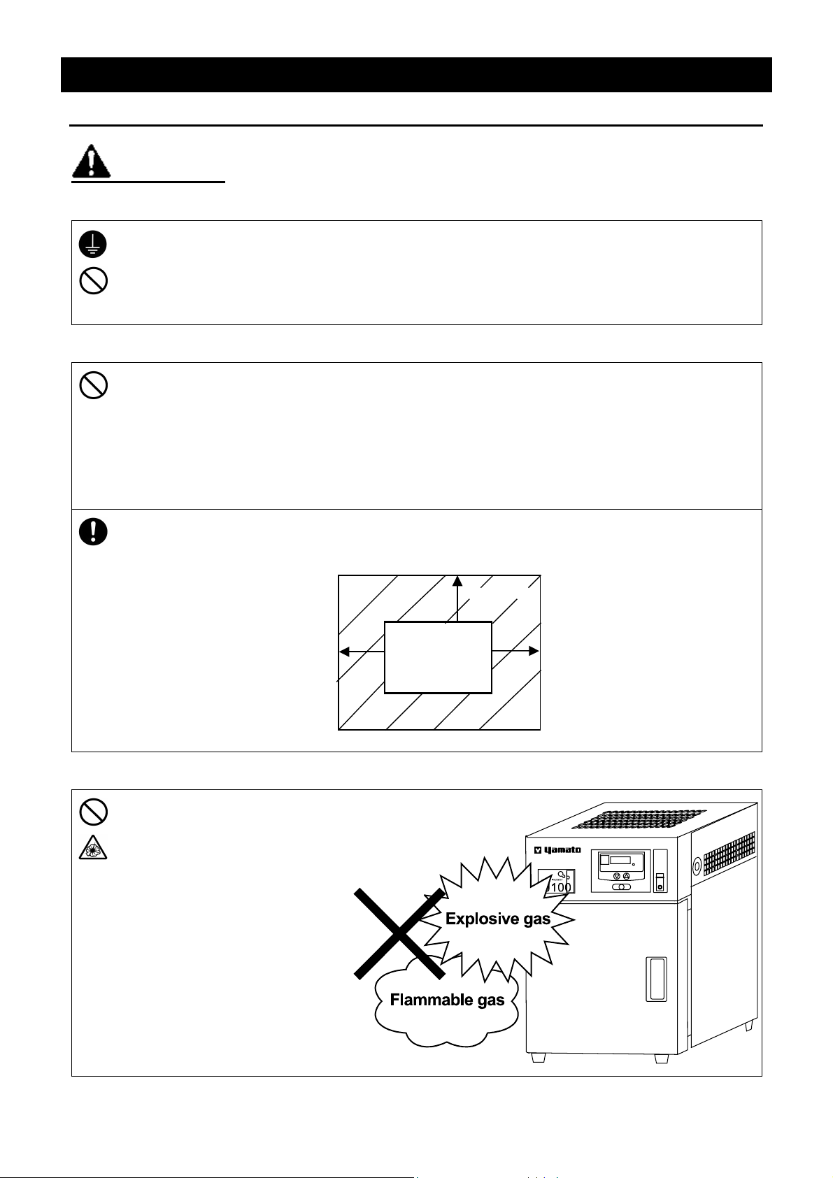
• Install this unit on a stable place with the space as shown below. Furthermore, make a space
30cm or more above this unit.
More than 15cm
More than
15cm
Main Unit
Front side
More than
15cm
3. Do not use this unit in an area where there is flammable or explosive gas
• Never use this unit in an area
where there is flammable or
explosive gas. This unit is not
explosion-proof. An arc may
be generated when the power
switch is turned ON or OFF,
and fire/explosion may result.
(To know about flammable or
explosive gas, refer to
page24 “List of Dangerous
Substances”.)
4
Requirements for Installation
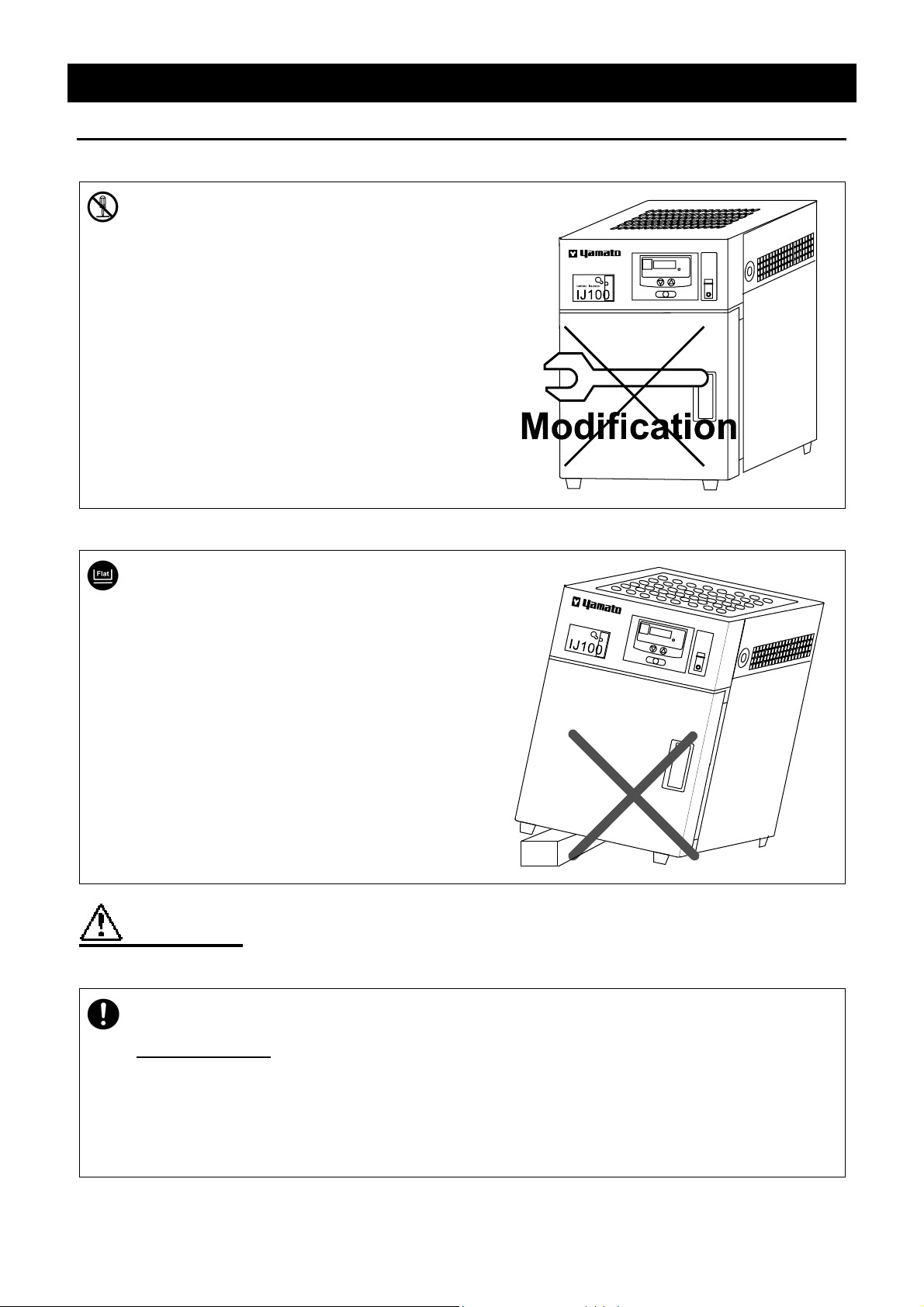
4. Do not modify
• Modification of this unit is strictly prohibited.
This could cause a failure.
Before Using this unit
5. Installation on horizontal surface
• Set this unit to the flattest place. Setting this
unit on rough or slope place could cause the
vibration or noise, or cause the unexpectible
trouble or malfunction.
CAUTION!
6. Choose a correct power distribution board or receptacle
• Choose a correct power distribution board or receptacle that meets the unit’s rated electric
capacity.
Electric capacity: 100V AC 3.5A
NOTE)
There could be the case that the unit does not run even after turning ON the power. Inspect
whether the voltage of the main power is lowered than the specified value, or whether other
device(s) uses the same power lin e of thi s unit. If the phenomena might be found, change the
power line of this unit to the other power line.
5
Requirements for Installation
Before Using this unit
CAUTION!
7. Before/after installing
• It may cause injure to a person if this unit falls down or moves by the earthquake and the
impact. etc..To prevent, take measures that the unit cannot fall down , and not inst all to busy
place.
8. Handling of power code
• Do not entangle the power cord. This will cause ov er heat ing and possibly a fire.
• Do not bend or twist the power cord, or apply excessiv e tension to it. This may cause a fire
and electrical shock.
• Do not lay the power cord under a desk or chair, and do not allow it to be pinched in order to
prevent it from being damaged and to avoid a fire or electrical shock.
• Keep the power cord away from any heating equipment such as a room heater. The cord's
insulation may melt and cause a fire or electrical shock.
• If the power cord becomes damaged (wiring exposed, breakage, etc.), immediately turn off the
power at the rear of this unit and shut off the main supply power. Then contact y our nearest
dealer for replacement of the power cord. Leaving it may cause a fire or electrical shock.
• Connect the power plug to the outlet which is supplied appropriate pow er and voltage.
9. Draining of condensation
• When the cooling device is operated, condensation may occur on the cooling surface. The
condensation is led out via the drain provided at the bottom on the rear t he unit . Therefore,
be sure to set the attached drain-receiving pan.
10. Setting shelf
• Fix the two shelves (attached accessory) on the appropriat e posit ion.
6
t
Before Using this unit
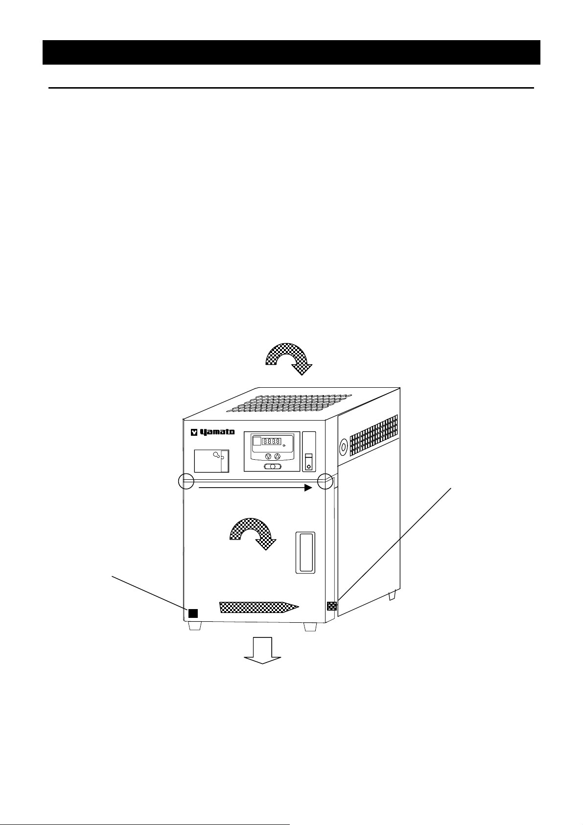
Change the Direction of Opening/Closi ng Door
This unit can be changed the direction of opening/closing the door easily.
The door opened/closed to the right or left can be selected according to the place where it is
installed and the convenience of operation.
The direction of opening/closing the door is set to left at the shipping from factory. If the
door should be opened/closed to the right, the direction of opening/closing the door can be
changed by the following procedure:
1. Lay down the main body backward in a way that t he door unit may come abov e.
2. By using phillips screwdriver, remove the hinge mounting screws fixing the door in the lower
part of the main body.
3. Pull off the door downward carefully.
4. Pull off the guide pin fixing the upper part of the door, and insert it into the screw hole on the
opposite side (right side).
5. Turn t he door 180 degrees, and insert it into the upper guide pin.
6. After adjusting the door position, fix the hinge in the lower part of the door.
7. Replace the main body to complete the procedure.
1. Lay down the main body.
4. Remove the guide pin, and
move it to the right side.
2. Remove the lower hinge
and move it to the righ
side.
設定温度
Lowtemp incubator
IJ100
5. Turn around the door
3. Pull out the door.
セット
ヒータ
6. Fix the lower hinge.
7

Main Unit
Description and Function of Each Part
Control panel
Independent overheating
prevention device
Specification plate
(Manufacture number)
Power switch
(Earth leakage breaker)
Front view
Cooling air inhalation
Door handle
Plate for drainage
Exhaust of cooling fan
Cooling air inhalation
Rear view
Power cord
8

②
③
⑤
Control Panel
Description and Function of Each Part
Main Indicator:
①
Heater Lamp:
②
Trouble Indicator:
③
▼▲(Up/Down) Key
④
Enter Key
⑤
Mainly displays measured temperature.
Lights up when electric power is supplied to the heater.
Blank in normal operation. Lights up when the device has a
trouble.
Use these keys when you change the parameters.
Use this key when you decide a modified parameter.
9

Sequence of Operation
Fixed Temperature Operation
Operation Method
1. Turn on t he pow er.
Changing Temperature Setting
1. Press the Enter key.
• The main indicator shows the current internal temperature.
MEASURED TEMP
• Fixed temperature operation is started with the target of the
previously set temperature.
When the power is t urned on, the controller resets a utomatically
to the condition immediately before the previous power-off.
ENTER
• The main indicator blinks the currently set temperature.
MEASURED TEMP
2. Press the ▼ key or ▲
key until the required
value is given in the
blinking number
3. When the temperature
reaches to the required
value, press the Enter
key.
ENTER
• The blinking indicator of the temperature setting is turned on,
and the fixed temperature operation is started toward the
newly set temperature.
10

g
Sequence of Operation
Temperature Preset Function Using Method
• Temperature. Preset is the function to memorize a specified temperature. It is useful to
register any temperature used frequently during operation.
• The preset temperature can be registered any time if the power switch is ON in normal
operation. To register this, follow the procedure shown below.
• Operation continues even when the temperature preset is being registered.
Operation Method
1. Press the Enter key
twice.
• The main indicator shows the temperature registered
currently.
• Then, the dot point to the left of the main indicator blinks and
indicates that the operation is in the preset temperature
registration mode.
Preset Temperature
Re
istration Mode
NOTE) If not registered, the main indicator blinks .
ENTER
MEASURED TEMP
Temperature Setting Method
1. Press the ▼ key or ▲
key until the required
value is given in the
main indicator.
2. When the required value
is given, press the
Enter key.
ENTER
• The previous temperature is deleted.
• Blinking of the previously set temperature is changed to the
display for the current measurement.
11

Operation Method
Independent overheating prevention device
For the safety device to prevent any over-temperature, an independent overheating prevention device
consisted of the circuits and sensors other than those for the controller is provided in addition to the
controller's automatic function (auto reset) to prevent over-temperature, thus configuring a double safety
measure.
Range of Set Temperature & Functions
This unit has two functions for preventing over-temperature; one is in the controller, and set
to automatically operate at the temperature set in the temperature regulator plus 6℃ when
delivered from the factory; the other is the temperature regulating dial provided in the upper
right part of this unit, which is used to set the activating temperature for over-temperature
prevention. Such a temperature setting completes a duplex function to prevent
over-temperature.
The independent overheating prevention device provided in the upper right part of this unit
sets temperatures in the range 0℃-120℃.
If the independent overheating prevention device is activated, the heater circuit is cut off,
and Er03 starts to blink.
If the independent overheating prevention device trips, the status is maintained until the
power is reset, while Er03 is not disabled.
If any wrong value is set for the activating temperature for over-temperature prevention,
units could fail to start, or the independent overheating prevention device could trip even
while the internal temperature is rising, or unexpected accidents including fire could be
occurred.
Using Method
Normally set this to a temperature about 10℃ (about 2 units in dial) higher than the
temperature set for the controller.
F or th e independent overheating prevention device to start at the required temperature, first
establish a stable operation at such a required temperature, and lower gradually the setting
dial of the independent overheating prevention device, and then check if the operation is
maintained with stable at the required temperature. Also set the bath temperature. To a
level higher than the temperature activating the independent overheating prevention device,
and check if the independent overheating prevention device trips at the required
temperature.
Caution
When cleaning the independent overheating prevention device or area around it, any touch
on the over-temperature prevention setting dial could change the set temperature.
Therefore, be sure to check if appropriate value is set for the temperature before starting
operation.
12

Handling Precautions
WARNING!
If a problem occurs
If smoke or strange odor should come out of this unit for some reason, turn off the power key
right away, and then turn off the circuit breaker and the main power. Immediately contact a
service technician for inspection. If this procedure is not followed, fire or electrical shock may
result. Never perform repair work yourself, since it is dangerous and not recommended.
Substances that cannot be used
Never use explosive substances, flammable substances and substances that include explosive
or flammable ingredients in this unit. Explosion or fire may occur. (Refer to page24 “List of
Dangerous Substances”.)
When the setting temperature is 35°C or less
When the setting temperature is 35°C or less, pay attention to dryness of sample. The cooling
device of this unit is operated by peltier ele ment. I t is set to operate when the setting temperature
is 35°C or less. If container for sample is open, sample may dry.
Condensation drainage
The cooling device may have condensation
during operation. It is drained through the port
on the base to the plate. Check the plate
sometime to avoid overflow.
CAUTION!
Do not step on this unit
Do not step on this unit. It w ill c ause injur y if this unit fall down or break.
Do not put anything on this unit
Do not put anything on this unit. I t will cause injury if fall.
During a thunder storm
During a thunderstorm, turn off the power key immediately, then turn off the circuit breaker and
the main power . If this procedure is not followed, fire or electrical shock may be caused.
When you open and close the door
When you open and close the door, be careful not to be hit your hands or face. It may cause
injury.
13

Handling Precautions
CAUTION!
Do not use corrosive sample
Stainless steel SUS304 is used for the main hot-air path. However, it may be corroded by strong
acid etc.. Care must be taken, vinyl chloride rubber may be corroded by some kind of solvent, ex
alkaline, oil, halogen etc.
Setting sample
•••• Do not put sample more than 5kg on the shelf provided. When you use some samples, keep
space between each of them.
• Temperature control may lose accuracy if many samples are set. Set sample making room
more than 30% of the shelf in order to keep accuracy of temperature.
It can be cooled to 0°C(minimum)by the product when the room t emperature is 20°C and there
is no load. The lowest temperature may change by quantity of sample.
Use under proper temperature range
Operational temperature range of this unit is 0 to 60℃. Never set the temperature out of that.
Do not put sample on the internal base
If sample is put directly on the base, device performance will be disturbed. Furthermore, internal
temperature will a bnormally rise and it will cause troub le. Never pu t sample on the b ase. Fix the
shelf on the metal fittings then set sample on it.
14

CAUTION!
Recovery of power failure
When power is supplied after a power failure, the device automatically st arts operation again with
the same state as just before the power failure. It is danger that the device starts unattached
operation after a power failure. We recommend for you to turn off the switch of this unit if a
power failure occurs during operation.
Do not pile up the units
Do not pile up the units like the figure.
This unit is not designed for that using.
Handling Precautions
設定温度
Lowtemp incubator
IJ100
ヒータ
セット
Do not put things on the top.
Don't put things on the top like a figure.
Cooling ability declines, and proper
control can't be done any more.
設定温度
Lowtemp incubator
IJ100
ヒータ
セット
After installing
It may cause injure to a person if this unit falls down or moves by the earthquake and the impact.
etc.. To prevent, take measures that the unit cannot fall down.
15

Daily Inspection and Maintenance
Maintenance Method
WARNING!
• Disconnect the power cable from the power source when doing an inspection or maintenance
unless needed.
• Perform the daily inspection and maintenance after returning the temperature of this unit to the
normal one.
• Do not disassemble this unit.
CAUTION!
Main unit maintenance
• Use a well-drained soft cloth to wipe dirt on this
unit. Do not use benzene, thinner or cleanser for
wiping. Do not scrub this unit. Deformation,
deterioration or color change may result in.
Monthly maintenance
• Check the earth leakage breaker function.
1. Connect the power cord.
2. Turn the breaker on.
3. Push the red test switch by a ballpoint pen etc.
4. If there is no problem, the earth leakage breaker will be turned off.
Cleaning of Heat radiate fin
• Clogging radiate fin causes its performance decreased and also
breakdown.
• Keep periodical cleaning depends on how the operating
environment or time is.
1.Lose 4 of upper shelf board screws and take the shelf off.
2.Take off the fan lead wire and 4 of fan screws.
3.Clean the surface of radi ate f in with vac u um cleaner after take off
the fin.
Fix them as it was following 3 to 1 order.
PRECAUTIONS: Pay attention not to crush the fin during cleaning.
Fin stop screw
Heat radiate fin
For any questions, contact the dealer who you purchased this unit from, or the nearest sales
division in our company.
16

t
Setting Air Jacket (Optional accessory)
1. Set the shelf at the lowest stage in a w ay that the side with margin may come innermost.
Set the shelf on the
lowest stage.
2. Set this on the shelf of the air jacket, and push it in.
3. Pus the air jacket inward until it hits the depth.
Enter this while adjusting i
closely to the edge of the
inner bath.
17
Long storage and disposal
When not using this unit for long term / When disposing
CAUTION!
When not using this unit for long term…
• Turn off the power and disconnect t he pow er cord.
WARNING!
When disposing…
• Keep out of reach of children.
• Treat as large trash.
Environmental protection should be considered
We request you to disassemble this unit as possible and recycle the reusable parts considering to
the environmental protection. The feature components of this unit and materials used are
listed below.
Component Name Material
Main Components of Exterior
Casing Steel plate, melamine resin baking finish
Interior Stainless steel plat e SUS 304
Air jacket (optional accessory) Aluminum, Neoprene rubber packing
Production plates PET resin film
Main Components of Cooling System
Heat absorb fin Aluminum
Heat radiate fin Copper , Lead solder
Heat radiate cover Steel plate, melamine resin baking finish
Parts attaching plate Steel plate, melamine resin baking finish
Main Components of Electric System
Heater Mica heater , Aluminum, Grass coating wire
Fan Aluminum, Copper wire and other composites
Circuit boards Composites of board, condenser, resist or, transformer, etc.
Power cord, Wiring material, etc. Wiring material of synthetic rubber coating and resin coating
18

In the Event of Failure…
Safety Device and Error Code
This unit has an automatic diagnosis function built in the controller and safety devices independent of the
controller . The table below shows the cause and the solution method when the safety device operates.
Error Code:
When an abnormal condition occurs, an error code and the trouble indicator blinks in the
controller, the buzzer sounds simultaneously. Record the error code and turn off the power of
device immediately.
Safety Device Notify Cause/Solution
Sensor trouble detection
Triac short-circuit detect ion
Heater disconnecting detection
(or independent overheating
prevention device is operates)
Main relay trouble detection
Electric circuit trouble detection
Trouble Shooting
Before call us...
“TROUBLE” lamp blinks,
“Er.01” blinks
“TROUBLE” lamp blinks,
“Er.02” blinks
“TROUBLE” lamp blinks,
“Er.03” blinks
“TROUBLE” lamp blinks,
“Er.10” blinks
“TROUBLE” lamp blinks,
“Er.15” blinks
• Temperature sensor is broken or
disconnected.
• Make a call for service.
• Triac is in short-circuit
• Make a call for service.
• Heater is disconnected.
• Independent overheating prevention
device is operates
• Make a call for service.
• Main relay is broken.
• Make a call for service.
• Failure in electric circuit.
• Make a call for service.
Condition Check the following.
The device does not start operation
when turning on the power switch.
Temperature fluctuates during the
operation.
In the case if the error other than listed above occurred, turn off the power switch and primary
power source immediately. Contact the shop of your purchase or nearest Yamato Scientific
Service Office.
• Power plug is not connected to the receptacle correctly.
• Power failure.
• Too much samples.
• The change of ambient temperature is remarkable.
• Samples are too moist.
• The power supply voltage is lower than t he proper value.
19

After Service and Warranty
In Case of Request for Repair
If the failure occurs, stop the operation, turn OFF the power switch, and unplug the power plug.
Please contact the sales agency that this unit was purchased, or the Yamato Scientific's sales
office.
< Check following items before contact >
◆ Model Name of Product
◆ Production Number
◆ Purchase Date
◆ About Trouble (in det ail as possible)
Minimum Retention Period of Performance Parts for Repair
The minimum retention period of performance parts for repair of this unit is 7 years after
discontinuance of this unit.
The "performance part for repair" is the part that is required to maintain this unit.
See the production plate attached to this unit.
20

Model IJ100
Operating temperature range
Temperature adjustment accuracy
Temperature distribution accuracy
Temperature rising time Approx. 40min. (20 to 60°C)
Performance
Temperature falling time Approx. 100min. (20 to 0°C)
Heating device Mica heater 120W
Two peltier cells, forced radiating method:
Cooling device
Configuration
Internal fan Axial fan (DC)
Controller Hitec IV
Temperature control system PID control of heater output by microcomputer
Temperature setting system
Operational mode Fixed temperature operation
Sensor Thermistor
Control Section
Additional function
Self-diagnostic function
Safety
Device
Preservation device
External dimensions
Internal dimensions
Internal capacity 15.6L
Standard
Door
Weight Approx. 20kg
Power supply 100V AC 50/60Hz 3.5A
Accessories
Optional accessories
It works continuous at the setting temperature below 35
(It is turned off at the setting temperature 35
Tem perature preset function (1 f or desired tem perature is able to
set/load)
Sensor error, Heater error, Triac error, Main relay error, Auto
overheating prevention
Earth leakage breaker, Independent overheating prevention
device
Shelf
×2 (Load: 5kg for each), Plate for drainage, Instruction
manual
Extra shelf (with m etal fittings), Air jacket made of aluminum (with
shelf)
The values shown on “Performance” are in power supply 100V AC.
Usable ambient temperature for this unit is 5 to 30℃.
0 to 60
±0.3℃ (the center of inner bath, set temp.:37℃)
±1.0℃ (the center of inner bath, set temp.:37℃)
Digital Setting by
(Air jacket installed: 200
(the direction of opening/closing is changeable)
℃ (room temp: 20℃, no load)*
350(W)
250(W)
Single door with magnet packing
Specification
℃ and over.)
type1
FR
▼▲ (up/down) Keys
×396(D)×535(H) mm
×250(D)×250(H) mm
×200×200 mm)
℃.
21

ELB
AC 100V
Symbol Part name Symbol Part name
ELB Earth leakage breaker F1, F2 Fan
T1, T2 Terminal block H Heater
TR1 Power transformer C1, C2 Peltier cell
X1, X2, X3 Relay PLANAR Control board
SSR SSR PIO Display board
CT1 Current detector TE1 Thermistor sensor
NF1 Noise filter SPS-1 Switching power supply
OH
T1
1.25
1.25
1
1.25
1.25
E
1.25
2
1.25
3
1.25
4
1.25
TR1
X1
J2
PI0
J10
Independent overheating
prevention device
23
1
SSR
4
J6
PLANAR
J8
X2
34 4 5
J7
1
CT1
3
+
NF1
2
SPS-1
4
-
T2
1
X2
2
3
J9
J5
1
2
J4
1
3
J11
4
TE1
+
SPS-2
-
SPS-2 Switching power supply for fan
Wiring Diagram
+
+
-
+
-
C1
+
C2
-
F1
F2
X3
OH
8
7
6
6
X3
X3
4
2
H
X1
22

Replacement Parts Table
Part Name Code No. Specification Manufacturer
Earth leakage breaker 2060000018
Terminal block 2070230001 TS046-1049 4P Yamato Scientific
Relay 2050000013 AJR6010 Matsushita
Relay 2050000040 AP5524K (HL2-HTM-AC100) Matsushita
SSR 2160000026 YLT-SSR-01 Yamato Scientific
Noise filter 2300010009 ZAG2206-11S 6A TDK
Fan 1 (for circulation) 2150000011 109R0812H4021 (DC12V 13W) Sanyo Denki
Fan 2 (for radiation) 2150000012 109R1212H1021 (DC12V 52W) Sanyo Denki
Heater 2260020014 Mica heater 120W Sakaguchi Dennetsu
Switching power supply board 2550000005 DC24V 144W Tenseiramda
Fan power supply board 2550000006 DC12V 15W Tenseiramda
Independent overheating
prevention device
Peltier cell 2600000001 17.5V 40W(950-127-085) Fellow Tech
Power transformer 1013200033 IV FR AC100 Yamato Scientific
PLANAR board 1240000057 IV FR Yamato Scientific
PIO board 1240000030 IV FR Yamato Scientific
1270010010 TO-1124-B Matsushita
FG32R-10-30
mA 10A
Fuji Denki
CPU 1180010011 H8/3256 IJ200 Yamato Scientific
Thermistor 1160050010 Thermistor Yamato Scientific
Current detector 2170010005 CTL-6-S-4-H URD
23

List of Dangerous Substances
Never use explosive substances, flammable substances and substances that include explosive
or flammable ingredients in this unit.
EXPLOSIVE
Ethylene glycol din it r at e (nit ro glycol), Glycerin trinitrat e (nitroglycerine), Cellul ose
nitrate (nitrocellulose), and other explosive nitrat e est ers
Reference
EXPLOSIVE:
FLAMMABLE
IGNITING:
OXIDIZING:
Trinitrobenzene, Trinitrotoluene, Trinitrophenol (picric acid), and other explosive
nitro compounds
Acetyl hidroperoxide (peracetic acid), Methyl ethyl ketone peroxide, Benzyl
peroxide, and other organic peroxides
Lithium (metal), Potassium (metal), Sodium (metal), Yellow phosphorus,
Phosphorus sulfide, Red phosphorus, Celluloid compounds, Calcium carbide,
Lime phosphate, Magnesium (powder), Aluminum (powder), Powder of metals
other than magnesium and aluminum, Sodium hydrosulfite
Potassium chlorate, Sodium chlorate, Ammonium chlorate, and other chlorate
Potassium perchlorate, Sodium perchlorate, Ammonium perchlorate, and other
perchlorate
Potassium peroxide, Sodium peroxide, Barium peroxide, and other inorganic
peroxide
Potassium nitrate, Sodium nitrate, Ammonium nitrate, and other nitrate
Sodium chlorite and other chlorites
Calcium hypochlorite and other hypochlorites
Ethyl ether, Gasoline, Acetaldehyde, Propylene chloride, Carbon disulfide, and
other flammable substances having a flash point of lower than -30℃
INFLAMMABLE
LIQUID:
FLAMMABLE
GAS:
Normal hexane, ethylene oxide, acetone, benzene, methyl ethyl ketone, and
other flammable substances having a flash point of -30℃ or higher but lower
than 0℃
Methanol, Ethanol, Xylene, Pentyl acetate (amyl acetate), and other flammable
substances having a flash point of 0℃ or higher but lower than 30℃
Kerosene, Light oil (gas oil), Oil of turpentine, Isopentyl alcohol (isoamyl alcohol),
Acetic acid, and other flammable substances having a flash point of 30℃ or
higher but lower than 65℃
Hydrogen, Acetylene, Ethylene, Methane, Propane, Butane, and other flammable
substances which assume a gaseous state at 15℃ and 1 atm
(Source: Appendix Table 1 of Article 6 of the Industrial Safety and Health Order in Japan)
24

Responsibility
Please follow the instructions in this document when using this unit. Yamato Scientific has no
responsibility for the accidents or breakdown of device if it is used with a failure to comply.
Never conduct what this document forbids. Unexpected accidents or breakdown may result in.
Note
◆ The contents of this document may be changed in future without notice.
◆ Any books with missing pages or disorderly binding may be replaced.
Instruction Manual for
Low Te mper at ur e I ncubat or
Model IJ 100
First Edition Mar. 19, 2001
Yamato Scientific Co., Ltd.
2-1-6 Nihonnbashi Honcho, Chuo-ku,
Tokyo, 103-8432, Japan
http://www.yamato-net.co.jp
25
 Loading...